WO2012147679A1 - Endoscopic device and measurement method - Google Patents
Endoscopic device and measurement method Download PDFInfo
- Publication number
- WO2012147679A1 WO2012147679A1 PCT/JP2012/060832 JP2012060832W WO2012147679A1 WO 2012147679 A1 WO2012147679 A1 WO 2012147679A1 JP 2012060832 W JP2012060832 W JP 2012060832W WO 2012147679 A1 WO2012147679 A1 WO 2012147679A1
- Authority
- WO
- WIPO (PCT)
- Prior art keywords
- pattern
- endoscope apparatus
- projection
- light
- image
- Prior art date
Links
Images


Classifications
-
- A—HUMAN NECESSITIES
- A61—MEDICAL OR VETERINARY SCIENCE; HYGIENE
- A61B—DIAGNOSIS; SURGERY; IDENTIFICATION
- A61B5/00—Measuring for diagnostic purposes; Identification of persons
- A61B5/103—Detecting, measuring or recording devices for testing the shape, pattern, colour, size or movement of the body or parts thereof, for diagnostic purposes
- A61B5/107—Measuring physical dimensions, e.g. size of the entire body or parts thereof
- A61B5/1077—Measuring of profiles
-
- A—HUMAN NECESSITIES
- A61—MEDICAL OR VETERINARY SCIENCE; HYGIENE
- A61B—DIAGNOSIS; SURGERY; IDENTIFICATION
- A61B1/00—Instruments for performing medical examinations of the interior of cavities or tubes of the body by visual or photographical inspection, e.g. endoscopes; Illuminating arrangements therefor
- A61B1/00002—Operational features of endoscopes
- A61B1/00004—Operational features of endoscopes characterised by electronic signal processing
- A61B1/00009—Operational features of endoscopes characterised by electronic signal processing of image signals during a use of endoscope
- A61B1/000095—Operational features of endoscopes characterised by electronic signal processing of image signals during a use of endoscope for image enhancement
-
- A—HUMAN NECESSITIES
- A61—MEDICAL OR VETERINARY SCIENCE; HYGIENE
- A61B—DIAGNOSIS; SURGERY; IDENTIFICATION
- A61B1/00—Instruments for performing medical examinations of the interior of cavities or tubes of the body by visual or photographical inspection, e.g. endoscopes; Illuminating arrangements therefor
- A61B1/00002—Operational features of endoscopes
- A61B1/00043—Operational features of endoscopes provided with output arrangements
- A61B1/00045—Display arrangement
-
- A—HUMAN NECESSITIES
- A61—MEDICAL OR VETERINARY SCIENCE; HYGIENE
- A61B—DIAGNOSIS; SURGERY; IDENTIFICATION
- A61B1/00—Instruments for performing medical examinations of the interior of cavities or tubes of the body by visual or photographical inspection, e.g. endoscopes; Illuminating arrangements therefor
- A61B1/00064—Constructional details of the endoscope body
- A61B1/00071—Insertion part of the endoscope body
- A61B1/0008—Insertion part of the endoscope body characterised by distal tip features
- A61B1/00096—Optical elements
-
- A—HUMAN NECESSITIES
- A61—MEDICAL OR VETERINARY SCIENCE; HYGIENE
- A61B—DIAGNOSIS; SURGERY; IDENTIFICATION
- A61B1/00—Instruments for performing medical examinations of the interior of cavities or tubes of the body by visual or photographical inspection, e.g. endoscopes; Illuminating arrangements therefor
- A61B1/00163—Optical arrangements
- A61B1/00174—Optical arrangements characterised by the viewing angles
- A61B1/00179—Optical arrangements characterised by the viewing angles for off-axis viewing
-
- A—HUMAN NECESSITIES
- A61—MEDICAL OR VETERINARY SCIENCE; HYGIENE
- A61B—DIAGNOSIS; SURGERY; IDENTIFICATION
- A61B1/00—Instruments for performing medical examinations of the interior of cavities or tubes of the body by visual or photographical inspection, e.g. endoscopes; Illuminating arrangements therefor
- A61B1/00163—Optical arrangements
- A61B1/00193—Optical arrangements adapted for stereoscopic vision
-
- A—HUMAN NECESSITIES
- A61—MEDICAL OR VETERINARY SCIENCE; HYGIENE
- A61B—DIAGNOSIS; SURGERY; IDENTIFICATION
- A61B1/00—Instruments for performing medical examinations of the interior of cavities or tubes of the body by visual or photographical inspection, e.g. endoscopes; Illuminating arrangements therefor
- A61B1/00163—Optical arrangements
- A61B1/00194—Optical arrangements adapted for three-dimensional imaging
-
- A—HUMAN NECESSITIES
- A61—MEDICAL OR VETERINARY SCIENCE; HYGIENE
- A61B—DIAGNOSIS; SURGERY; IDENTIFICATION
- A61B1/00—Instruments for performing medical examinations of the interior of cavities or tubes of the body by visual or photographical inspection, e.g. endoscopes; Illuminating arrangements therefor
- A61B1/04—Instruments for performing medical examinations of the interior of cavities or tubes of the body by visual or photographical inspection, e.g. endoscopes; Illuminating arrangements therefor combined with photographic or television appliances
- A61B1/05—Instruments for performing medical examinations of the interior of cavities or tubes of the body by visual or photographical inspection, e.g. endoscopes; Illuminating arrangements therefor combined with photographic or television appliances characterised by the image sensor, e.g. camera, being in the distal end portion
-
- A—HUMAN NECESSITIES
- A61—MEDICAL OR VETERINARY SCIENCE; HYGIENE
- A61B—DIAGNOSIS; SURGERY; IDENTIFICATION
- A61B1/00—Instruments for performing medical examinations of the interior of cavities or tubes of the body by visual or photographical inspection, e.g. endoscopes; Illuminating arrangements therefor
- A61B1/06—Instruments for performing medical examinations of the interior of cavities or tubes of the body by visual or photographical inspection, e.g. endoscopes; Illuminating arrangements therefor with illuminating arrangements
- A61B1/0605—Instruments for performing medical examinations of the interior of cavities or tubes of the body by visual or photographical inspection, e.g. endoscopes; Illuminating arrangements therefor with illuminating arrangements for spatially modulated illumination
-
- A—HUMAN NECESSITIES
- A61—MEDICAL OR VETERINARY SCIENCE; HYGIENE
- A61B—DIAGNOSIS; SURGERY; IDENTIFICATION
- A61B1/00—Instruments for performing medical examinations of the interior of cavities or tubes of the body by visual or photographical inspection, e.g. endoscopes; Illuminating arrangements therefor
- A61B1/06—Instruments for performing medical examinations of the interior of cavities or tubes of the body by visual or photographical inspection, e.g. endoscopes; Illuminating arrangements therefor with illuminating arrangements
- A61B1/0661—Endoscope light sources
- A61B1/0676—Endoscope light sources at distal tip of an endoscope
-
- A—HUMAN NECESSITIES
- A61—MEDICAL OR VETERINARY SCIENCE; HYGIENE
- A61B—DIAGNOSIS; SURGERY; IDENTIFICATION
- A61B5/00—Measuring for diagnostic purposes; Identification of persons
- A61B5/0059—Measuring for diagnostic purposes; Identification of persons using light, e.g. diagnosis by transillumination, diascopy, fluorescence
- A61B5/0082—Measuring for diagnostic purposes; Identification of persons using light, e.g. diagnosis by transillumination, diascopy, fluorescence adapted for particular medical purposes
- A61B5/0084—Measuring for diagnostic purposes; Identification of persons using light, e.g. diagnosis by transillumination, diascopy, fluorescence adapted for particular medical purposes for introduction into the body, e.g. by catheters
-
- A—HUMAN NECESSITIES
- A61—MEDICAL OR VETERINARY SCIENCE; HYGIENE
- A61B—DIAGNOSIS; SURGERY; IDENTIFICATION
- A61B5/00—Measuring for diagnostic purposes; Identification of persons
- A61B5/103—Detecting, measuring or recording devices for testing the shape, pattern, colour, size or movement of the body or parts thereof, for diagnostic purposes
- A61B5/107—Measuring physical dimensions, e.g. size of the entire body or parts thereof
- A61B5/1076—Measuring physical dimensions, e.g. size of the entire body or parts thereof for measuring dimensions inside body cavities, e.g. using catheters
-
- G—PHYSICS
- G02—OPTICS
- G02B—OPTICAL ELEMENTS, SYSTEMS OR APPARATUS
- G02B23/00—Telescopes, e.g. binoculars; Periscopes; Instruments for viewing the inside of hollow bodies; Viewfinders; Optical aiming or sighting devices
- G02B23/24—Instruments or systems for viewing the inside of hollow bodies, e.g. fibrescopes
- G02B23/2407—Optical details
- G02B23/2423—Optical details of the distal end
-
- G—PHYSICS
- G02—OPTICS
- G02B—OPTICAL ELEMENTS, SYSTEMS OR APPARATUS
- G02B23/00—Telescopes, e.g. binoculars; Periscopes; Instruments for viewing the inside of hollow bodies; Viewfinders; Optical aiming or sighting devices
- G02B23/24—Instruments or systems for viewing the inside of hollow bodies, e.g. fibrescopes
- G02B23/2407—Optical details
- G02B23/2461—Illumination
- G02B23/2469—Illumination using optical fibres
-
- G—PHYSICS
- G06—COMPUTING; CALCULATING OR COUNTING
- G06T—IMAGE DATA PROCESSING OR GENERATION, IN GENERAL
- G06T7/00—Image analysis
- G06T7/50—Depth or shape recovery
- G06T7/521—Depth or shape recovery from laser ranging, e.g. using interferometry; from the projection of structured light
-
- H—ELECTRICITY
- H04—ELECTRIC COMMUNICATION TECHNIQUE
- H04N—PICTORIAL COMMUNICATION, e.g. TELEVISION
- H04N23/00—Cameras or camera modules comprising electronic image sensors; Control thereof
- H04N23/56—Cameras or camera modules comprising electronic image sensors; Control thereof provided with illuminating means
-
- H—ELECTRICITY
- H04—ELECTRIC COMMUNICATION TECHNIQUE
- H04N—PICTORIAL COMMUNICATION, e.g. TELEVISION
- H04N23/00—Cameras or camera modules comprising electronic image sensors; Control thereof
- H04N23/50—Constructional details
- H04N23/555—Constructional details for picking-up images in sites, inaccessible due to their dimensions or hazardous conditions, e.g. endoscopes or borescopes
Definitions
- the present invention relates to an endoscope apparatus and a measuring method, and more specifically, an endoscope apparatus that measures a three-dimensional shape of a surface of a test object by projecting a pattern such as a stripe on the test object, and a streak on the test object.
- the present invention relates to a method for measuring the three-dimensional shape of the surface of a test object by projecting a pattern such as the above.
- an endoscope (endoscope device) having a long insertion portion and having observation means such as an optical system and an image sensor at the tip of the insertion portion is used.
- observation means such as an optical system and an image sensor at the tip of the insertion portion
- a plurality of fringe images obtained by projecting fringes on the test object are obtained while shifting the phase of the fringes, and a known phase shift method using the plurality of fringe images is used.
- a known phase shift method using the plurality of fringe images is used. What calculates the three-dimensional shape of a test object is known.
- Patent Document 1 describes an endoscope apparatus in which two projection windows for projecting stripes are provided on the distal end surface of an insertion portion.
- An object of the present invention is to provide an endoscope apparatus in which an insertion portion is reduced in diameter. It is another object of the present invention to provide a measurement method that can accurately measure a three-dimensional shape even in an endoscope apparatus in which an insertion portion has a reduced diameter. Furthermore, it aims at providing the measuring method which measures a three-dimensional shape in a short time using an endoscope apparatus.
- the endoscope apparatus is an endoscope apparatus that performs measurement of the test object using a pattern projection image of the test object on which a light brightness / darkness pattern is projected.
- An endoscope apparatus includes an insertion unit, an imaging unit, an illumination unit, and a pattern projection unit.
- the imaging unit is provided at a distal end of the insertion unit and acquires an image of the test object.
- the illumination unit emits illumination light that illuminates the observation field of view of the imaging unit.
- the pattern projection unit projects the light and dark pattern onto the test object.
- An objective optical system that forms an image of the test object on the imaging unit, one or more illumination windows that emit the illumination light, and the test object from the pattern projection unit are provided on the distal end surface of the insertion unit.
- a projection window for projecting the light and dark pattern onto an object.
- the objective optical system has an optical axis on the emission side from the objective optical system to the imaging unit among the optical axes of the objective optical system, the center of the insertion unit. It arrange
- the objective optical system is a direct-view objective optical system in which both the incident-side optical axis and the outgoing-side optical axis are parallel to the central axis. Furthermore, the objective optical system is provided on a distal end surface of the distal end portion of the insertion portion, and is disposed at a position decentered with respect to the central axis.
- the projection window is provided on the distal end surface, and is disposed at a position eccentric with respect to the central axis of the insertion portion.
- the objective optical system is exposed on the outer peripheral surface of the distal end portion of the insertion portion, and the optical axis on the incident side is arranged at a position twisted with respect to the central axis.
- This is a side view type objective optical system.
- the projection window is exposed on the outer peripheral surface of the distal end portion of the insertion portion, and the projection window is viewed from the thickness direction of the projection window.
- a center line that passes through the center of the projection window and extends in the thickness direction of the projection window is disposed at a twisted position with respect to the center axis of the insertion portion.
- the objective optical system is exposed on the outer peripheral surface of the distal end portion of the insertion portion, and the optical axis on the incident side intersects the central axis of the insertion portion.
- This is a side-viewing objective optical system.
- the projection window has a plane in which the center of the projection window when the projection window is viewed from the thickness direction of the projection window is defined by the central axis of the insertion portion and the optical axis on the incident side.
- the insertion portion is disposed on the outer peripheral surface of the distal end portion.
- the pattern projection unit has one or more line-shaped parallel patterns.
- the pattern projection unit includes a projection light source, a pattern generation unit that changes the intensity distribution of the light emitted from the projection light source, and generates the light-dark pattern. Is provided.
- the endoscope apparatus includes an optical fiber that guides light emitted from the projection light source to the pattern generation unit. Further, the projection light source is provided on a proximal end side of the insertion portion, and the pattern generation portion is provided on a distal end portion of the insertion portion.
- the projection light source and the pattern generation unit are provided at a distal end of the insertion unit.
- the endoscope apparatus includes an optical fiber that is emitted from the projection light source and guides the light / dark pattern generated by the pattern generation unit to a distal end side of the insertion unit. Prepare. Further, the projection light source and the pattern generation unit are provided on the proximal end side of the insertion unit.
- the endoscope apparatus includes an optical adapter that can be detachably attached to a distal end portion of the insertion portion, and the pattern generation portion is provided in the optical adapter. .
- the projection light source is provided in the optical adapter.
- the endoscope apparatus includes switching means for switching between the light for projecting the bright and dark pattern and the illumination light.
- the measurement method according to the sixteenth aspect of the present invention is a measurement method for measuring the three-dimensional shape of a test object using an endoscope (endoscope device).
- a predetermined light / dark pattern is projected onto the test object from one place of the endoscope, and a portion of the test object on which the light / dark pattern is projected is imaged. Then, at least one pattern projection image is acquired, and the three-dimensional shape of the portion on which the light and dark pattern is projected is measured using the pattern projection image.
- the measurement method according to the seventeenth aspect of the present invention is a measurement method for measuring a three-dimensional shape of a test object using an endoscope apparatus.
- a predetermined fringe pattern is projected onto the test object from one location of the endoscope apparatus, and a portion of the test object on which the fringe pattern is projected is projected.
- An image is captured to obtain a single fringe image, and the three-dimensional shape of the portion onto which the fringe pattern is projected is measured from the single fringe image using a spatial phase shift method or a Fourier transform method.
- a measuring method comprising: obtaining a bright field image of a portion onto which the fringe pattern is projected at least before or after obtaining the one fringe image.
- the measurement method acquires at least one bright field image before and after acquiring the one striped image.
- At least two images selected for detecting that the position of the endoscope device has shifted are selected from the bright field images. Is done.
- the diameter of the insertion portion can be reduced.
- the measurement method according to the aspect of the present invention it is possible to accurately measure a three-dimensional shape even in an endoscope apparatus in which the insertion portion has a reduced diameter.
- the three-dimensional shape can be measured by analyzing one striped image photographed using the endoscope apparatus.
- the three-dimensional shape can be measured in a short time using the endoscope apparatus.
- FIG. 1 is a block diagram illustrating a configuration of an endoscope apparatus 1 according to the present embodiment.
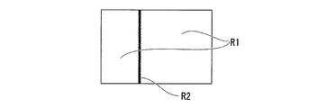
- FIG. 2 is a schematic diagram showing a light / dark pattern projected by the endoscope apparatus 1.
- the endoscope apparatus 1 is used for internal observation of a test object, observation of a test object at a position where a normal observation apparatus is difficult to access, and the like.
- the endoscope apparatus 1 includes a long insertion portion 10 and a main body portion 20 to which a proximal end of the insertion portion 10 is connected.
- the insertion part 10 is formed in a tubular shape, and is inserted into the inside of the test object or an access path to the test object.
- the insertion unit 10 includes an imaging unit 30 that acquires an image of the test object, an illumination unit 40 that illuminates the observation field of view in front of the insertion unit 10, and a pattern projection unit 50 that projects a light / dark pattern onto the test object. It has been.
- the pattern projection unit 50 projects a fringe pattern onto the test object as a bright and dark pattern.
- the distal end surface 10a of the insertion unit 10 is provided with an opening 11 for allowing external light to enter the objective optical system 32 of the imaging unit 30, and illumination for irradiating illumination light from the illumination unit 40 forward of the insertion unit.
- a window 12 and a projection window 13 for irradiating the stripes from the pattern projection unit 50 in front of the insertion unit are provided.
- the imaging unit 30 includes an imager 31 disposed near the distal end of the insertion unit 10, an objective optical system 32 disposed in front of the imager 31, and an imager control unit 33 connected to the imager 31. .
- various known configurations including various image sensors such as a CCD and a CMOS can be appropriately selected and used.
- the objective optical system 32 is disposed in the opening 11 of the insertion portion 10. Reflected light within an observation field having a predetermined field angle and defined by the field angle is incident on the imager 31 to form an image of the test object.
- the objective optical system 32 includes a light transmissive cover member 32 a that seals the opening 11.
- the imager control unit 33 is provided in the main body unit 20 and is connected to the imager 31 by a wiring 34 extending in the insertion unit 10.
- the imager control unit 33 performs various controls such as driving of the imager 31 and setting for acquiring a video signal.
- the illumination unit 40 includes a first light source 41, an illumination optical system 42, a first fiber bundle 43 that guides light from the first light source 41 to the illumination optical system 42, and between the first light source 41 and the first fiber bundle 43. And a first incident optical system 44.
- the first light source 41 is a general white light source and is disposed inside the main body 20.
- a light emitting element such as an LED or a laser, a halogen lamp, or the like can be employed.
- the illumination optical system 42 is attached at or near the distal end of the insertion portion 10.
- the illumination optical system 42 includes a light transmissive cover member 42 a provided in the illumination window 12 of the insertion unit 10 and a lens group (not shown).
- the illumination optical system 42 spreads the light emitted from the first light source 41 in the field of view suitable for the angle of view of the objective optical system 32 and emits it from the illumination window 12 to illuminate the entire observation field.
- the first fiber bundle 43 extends from the vicinity of the illumination optical system 42 to the vicinity of the first light source 41 in the main body 20 through the insertion portion 10.
- a general light guide can be used.
- the first incident optical system 44 converges the light emitted from the first light source 41 to the same extent as the diameter of the first fiber bundle 43 and efficiently introduces it into the first fiber bundle 43.
- the pattern projection unit 50 includes a second light source 51 (projection light source), a projection optical system 52, a second fiber bundle 53 that guides light from the second light source 51 to the projection optical system 52, a second light source 51, and a second light source 51.
- a second incident optical system 54 disposed between the fiber bundle 53 and a pattern generation unit 55 disposed on the optical path of the light emitted from the second light source 51 is provided.
- the second light source 51 is a white light source similar to the first light source 41 and is disposed inside the main body 20.
- the second light source 51 may be a light source that emits light having a wavelength different from that of the first light source 41.
- the projection optical system 52 is attached at or near the distal end of the insertion portion 10.
- the projection optical system 52 includes a light transmissive cover member 52 a provided in the projection window 13 of the insertion unit 10. Note that the cover member 52a provided in the projection window 13 may have a lens shape.
- the projection optical system 52 projects the light emitted from the second light source 51 into a field of view suitable for the angle of view of the objective optical system 32 and projects it from one projection window 13 into the observation field.
- the second fiber bundle 53 extends from the vicinity of the projection optical system 52 through the insertion section 10 to the vicinity of the second light source 51 in the main body section 20.
- a general light guide can be used similarly to the first fiber bundle 43.
- the second incident optical system 54 converges the light emitted from the second light source 51 to the same extent as the diameter of the second fiber bundle 53 and efficiently introduces it into the second fiber bundle 53.
- the pattern generation unit 55 can use a known configuration that can form a plurality of fringe patterns out of phase. For example, a configuration in which a slit plate having a plurality of slits is moved by an actuator, or a transparent plate made of glass, resin, or the like on which a plurality of fringe patterns whose phases are shifted from each other is moved by an actuator is used.
- a liquid crystal shutter module that can switch between transmission and non-transmission of light for each element
- a MEMS (microelectronic device system) mirror module that includes a fine reflection mirror for each element, and the like may be used as the pattern generation unit 55.
- the pattern generation unit 55 Good.
- the control is performed for each element, a plurality of fringe patterns whose phases are shifted can be formed without moving the entire pattern generation unit 55. Therefore, there is an advantage that the configuration of the pattern projection unit 50 can be simplified.
- the fringe pattern is switched by the pattern control unit 56 connected to the pattern generation unit 55.
- the shape of the light / dark pattern is not limited to the stripe pattern, and may be a plurality of line-like parallel lines as shown in FIG.
- a single line (described later) as shown in FIG. 9 may be used. Further, it may be a plurality of points, a lattice pattern in which a plurality of vertical lines and horizontal lines intersect, or a concentric pattern.
- the 1st light source 41 and the 2nd light source 51 are connected to the light source control part 21 which controls on / off of these light sources.
- the imager control unit 33, the pattern control unit 56, and the light source control unit 21 are connected to a main control unit 22 that controls the entire endoscope apparatus 1.
- the main control unit 22 is connected to an operation unit 23 for a user to make various inputs to the endoscope apparatus 1.
- the main control unit 22 is connected to a main storage device (RAM 24).
- an auxiliary storage device 25 such as a storage device having a rewritable nonvolatile memory or a magnetic storage device is electrically connected to the main control unit 22.
- a ROM 26 (or EPROM, EEPROM, or the like) that records firmware or the like may be connected to the main control unit 22 as necessary.
- the video processor 27 that processes the video signal acquired by the imager 31 is connected to the imager control unit 33 and the main control unit 22.
- a monitor 28 that displays a video signal processed by the video processor 27 as an image is connected to the video processor 27.
- the measurement method according to the first embodiment of the present invention is a measurement method for measuring the three-dimensional shape of a test object using the endoscope apparatus 1.
- the endoscope apparatus 1 When using the endoscope apparatus 1, first, the user inserts the insertion portion 10 into the inside of the test object or an access path to the test object such as a duct, and the like, until the predetermined observation site is reached. Advance the tip. The user switches the observation mode for observing a desired part of the test object and the measurement mode for measuring the three-dimensional shape of the test part, as necessary, to inspect the test object.
- the light source control unit 21 controls the first light source 41 to be turned on and the second light source 51 to be turned off.
- the fringe pattern is not projected from the pattern projection unit 50, and the observation field is illuminated with white light from the illumination unit 40, and the observation field is illuminated (hereinafter, this illumination state is referred to as “observation state”).
- the illuminated image of the object is formed on the imager 31 through the objective optical system 32.
- the video signal sent from the imager 31 is processed by the video processor 27 and displayed on the monitor 28. The user can observe the test object from the image of the test object displayed on the monitor 28, and can store the image as necessary.
- the user When switching from the observation mode to the measurement mode, the user inputs an instruction to switch the mode.
- a known input device can be adopted as an input device for inputting an instruction for switching modes.
- a configuration in which a switch is provided in the operation unit 23 or a configuration in which the monitor 28 is changed to a touch panel to be a software switch can be employed.
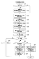
- the measurement image photographing process (see FIG. 3) is started in the main control unit 22.
- step S1 it is determined whether or not the endoscope apparatus 1 is in an observation state (step S1 shown in FIG. 3). If it is determined in step S1 that it is in the observation state, the process proceeds to step S3, and if it is in a state other than the observation state (for example, a measurement state described later) in step S1, the process proceeds to step S2. This ends step S1.
- Step S2 is a step of switching the endoscope apparatus 1 to the observation state.
- the first light source 41 is on-controlled and the second light source 51 is off-controlled.
- the pattern projection unit 50 does not project the fringe pattern, and the illumination unit 40 irradiates the observation field with white light, and the observation field is illuminated.
- Step S2 is complete
- Step S ⁇ b> 3 is a step of capturing an image of the test object that is not projected with the fringe pattern and is illuminated with white light from the illumination unit 40.
- step S ⁇ b> 3 an image is acquired by the imager 31 of the imaging unit 30 in a state where the test object is illuminated with white light from the illumination unit 40 (hereinafter, an image captured in the observation state is referred to as a “bright field image”). Called).
- the bright field image photographed in step S3 is temporarily stored in the RAM 24.
- Step S3 is complete
- Step S4 is a branching step for capturing a desired number of pattern projection images.
- the predetermined number N of pattern projection images to be captured is compared with the number of pattern projection images currently stored in the RAM 24, and the number of pattern projection images stored in the RAM 24 is less than the number N of planned projection images. If so, the process proceeds to step S5. On the other hand, if the number of pattern projection images stored in the RAM 24 is the scheduled number N, the process proceeds to step S7. This ends step S4.
- Step S5 is a step of projecting the fringe pattern onto the test object.
- the first light source 41 is turned off and the second light source 51 is turned on based on a command from the main control unit 22.
- the white light irradiated from the illumination unit 40 is turned off, and the fringe pattern is projected from the pattern projection unit 50 onto the test object.
- the fringe pattern projected on the test object is a pattern in which bright portions R ⁇ b> 1 due to a white light source and dark portions R ⁇ b> 2 shielded by the pattern generation unit 55 are alternately arranged.
- the pattern generation unit 55 operates the actuator to set the phase of the fringe pattern to an appropriate phase.
- a state in which appropriate stripes are projected onto the test object from one place hereinafter, this state is referred to as a “pattern projection state”.
- Step S5 is complete
- Step S6 is a step of capturing a pattern projection image in the pattern projection state.
- the fringe pattern projected onto the test object is a pattern that changes according to the three-dimensional shape of the test object.
- an image is acquired by the imager 31 of the imaging unit 30 (hereinafter, an image photographed in a pattern projection state is referred to as a “pattern projection image”).
- the pattern projection image photographed in step S6 is temporarily stored in the RAM 24. This ends step S6 and returns to step S4.
- Steps S4 to S6 are repeated until the number of pattern projection images to be shot reaches the planned number of shots N.
- the phase of the fringe pattern is changed as appropriate, and, for example, a total of N images of the test object on which the fringes with different phases are projected are taken one by one.
- Step S7 is a step of switching the endoscope apparatus 1 to the observation state.
- the first light source 41 is on-controlled and the second light source 51 is off-controlled.
- the pattern projection unit 50 does not project the fringe pattern, and the illumination unit 40 irradiates the observation field with white light, and the observation field is illuminated.
- Step S7 is complete
- Step S ⁇ b> 8 is a step of capturing an image of the test object illuminated with white light from the illuminating unit 40 without a stripe pattern being projected.
- step S ⁇ b> 8 a bright field image is captured by the imager 31 of the imaging unit 30 in a state where the test object is illuminated with white light from the illumination unit 40.
- the bright field image photographed in step S8 is temporarily stored in the RAM 24.
- Step S8 is complete
- step S9 based on the images (bright field image and pattern projection image) photographed between step S3 and step S8, the relative movement between the insertion unit 10 and the subject between step S3 and step S8 ( (Hereinafter referred to as “blur”).
- step S9 first, two images are selected from at least one of the bright field image and the stripe image stored in the RAM 24. For example, in the first embodiment, a bright-field image captured before capturing N pattern projection images and a bright-field image captured after capturing N pattern projection images are selected. Subsequently, the same feature point is detected from the two selected images, and the coordinates of the feature point in the two images are calculated. Step S9 is completed now and it progresses to Step S10.
- Step S10 is a step of branching the process by determining blurring of the two images using the feature points detected in step S9.
- step S10 if the coordinates of the feature points in the two images are the same in each image, it is determined that there is no blur between the first image and the subsequent image, and the process proceeds to step S11. On the other hand, if the coordinates of the feature points in the two images are different in each image, it is determined that there is a blur between the first image and the subsequent image, and a blur has occurred. Is displayed on the monitor 28 (step S14), and the series of processes is terminated. This ends step S10.
- Step S11 is a step in which the user selects whether to perform three-dimensional measurement using the captured pattern projection image now or later.
- step S11 for example, an inquiry such as “Perform measurement?” Is displayed on the monitor 28, and the user is prompted to input whether to perform three-dimensional measurement using the captured pattern projection image. If there is an input that the measurement can be performed, the process proceeds to step S12. If there is an input that the measurement is not performed, the process proceeds to step S15. This ends step S11.
- Step S12 is a step of performing analysis for performing three-dimensional measurement.
- the three-dimensional shape is analyzed based on the pattern projection image stored in the RAM 24.
- the three-dimensional shape of the test object is analyzed by, for example, a known temporal phase shift method using N pattern projection images having different phases.
- the analysis result of the three-dimensional shape is generated as a text file or a binary file, and is stored in the auxiliary storage device 25 together with N pattern projection images.
- step S12 may be performed as the background process of step S11 simultaneously with the start of step S11. Step S12 is completed now and it progresses to Step S13.
- step S13 the display on the monitor 28 is shifted to the screen of various measurement modes, and the measurement result is displayed on the monitor 28 using the information stored in step S12.
- step S13 the result of analysis in step S12 is overlaid on the bright field image acquired in step S3 (or the bright field image acquired in step S8).
- the three-dimensional shape is displayed on the monitor 28. Thereby, the user can know the three-dimensional shape of the test object.
- Step S13 is complete
- Step S15 is a step branched from step S11 described above, and is a step for performing information processing necessary for displaying the measurement result later.
- step S15 as in step S12, the three-dimensional shape is analyzed based on the pattern projection image stored in the RAM 24.
- the three-dimensional shape of the test object is analyzed by the temporal phase shift method using N pattern projection images having different phases.
- the bright field image, the pattern projection image, the analysis result of the three-dimensional shape, and the optical parameters used for the analysis are stored in the auxiliary storage device 25 as a binary file or a text file, respectively.
- Step S15 is complete
- the projection window 13 of the pattern projection unit 50 is provided at one place on the distal end surface 10a of the insertion unit 10, it is inserted. Compared with the case where two projection windows 13 are provided on the distal end surface 10a of the portion 10, the insertion portion 10 can be made thinner.
- the projection windows 13 for projecting the stripe pattern are provided at a plurality of positions as in the conventional case, the area occupied by the projection window 13 on the distal end surface 10a of the insertion portion 10 of the endoscope apparatus 1 is large, and the illumination window 12 It is difficult to increase the occupation area of the objective optical system 32. For example, if the area occupied by the illumination window 12 is small, the amount of illumination light may be insufficient. Further, if the area occupied by the objective optical system 32 is small, it is difficult to increase the diameter of the lens, and the image may become dark.
- the endoscope apparatus 1 since the projection window 13 that projects the fringe pattern is one, the occupation area of the illumination window 12 and the objective optical system 32 is increased. Can do. As a result, a brighter image can be acquired even with the insertion section 10 having a thickness equivalent to that of a conventional endoscope. In addition, even the insertion unit 10 having a diameter smaller than that of a conventional endoscope can acquire an image with brightness equal to or higher than that of the conventional endoscope.
- the measurement method of the first embodiment of the present invention even in an environment in which a fringe pattern is projected from one projection window 13 in the endoscope apparatus 1 in which the insertion portion 10 is reduced in diameter, it is accurate. A three-dimensional shape can be measured.
- blur is detected using bright field images before and after pattern projection images are taken, and when it is determined that there is no blur, a three-dimensional shape is analyzed.
- the analysis is not performed while the fringe patterns on the plurality of pattern projection images are shifted. For this reason, the analysis precision of a three-dimensional shape can be improved. Further, it is possible to suppress a positional deviation when the measurement result using the pattern projection image is displayed as an overlay on the bright field image.
- Modification 1 of the first embodiment a modification of the endoscope apparatus 1 and the measurement method described in the first embodiment will be described.
- This modification is different from the above-described first embodiment in that a pattern generating unit 55A (see FIG. 1) is provided instead of the pattern generating unit 55.
- the pattern generation unit 55A cannot project light and dark patterns having different phases.
- the pattern generation unit 55A is configured to be able to project a light / dark pattern having a specific phase onto the test object. That is, the pattern generation unit 55A of the present modification is configured in a small size without an actuator that moves a slit plate or the like.
- the method for measuring the three-dimensional shape of the test object is also different.
- the measurement method of the present modification will be described focusing on the point of difference in processing content from the first embodiment described above.
- the scheduled number of shots N in step S4 is 1, and one pattern projection image is shot without repeating steps S4 to S6 in the above-described embodiment, and the process proceeds to step S7.
- step S12 and step S15 a three-dimensional shape is analyzed by a spatial phase shift method or a Fourier transform method using one pattern projection image.
- the measurement method of this modification is a method that can be similarly applied even if the pattern generation unit 55 includes an actuator that moves a slit plate or the like, and a temporal phase shift method using a plurality of pattern projection images. 3D shape can be analyzed quickly compared to.
- a pattern generation unit 55A (see FIG. 1) is provided, and the pattern projection unit 50 projects a single pattern of bright or dark lines as shown in FIG. 9 onto the test object. It is configured to be able to.
- FIG. 9 shows a case where one streak (straight line) dark part R2 is projected in the bright part R1. Note that one streaky bright portion R1 may be projected in the dark portion R2.
- the one pattern itself projected from the pattern projection unit 50 does not move or change its shape or direction. That is, the pattern generation unit 55A of the present modification is configured in a small size without an actuator that moves a slit plate or the like.
- the measurement method of the three-dimensional shape of the test object is also different.
- the measurement method of the present modification will be described focusing on the point of difference in processing content from the first embodiment of the above-described modification 1.
- step S12 and step S15 a three-dimensional shape is analyzed by a light cutting method using one pattern projection image.
- a three-dimensional shape is analyzed on a single pattern using a single pattern projection image. Therefore, compared to the case of analyzing the entire surface of a single pattern projection image in the first embodiment described above, although the portion where the three-dimensional shape can be measured is limited, the analysis time can be greatly shortened. it can.
- the measurement method of this modification is a method that can be similarly applied even if the pattern generation unit 55 includes an actuator that moves a slit plate or the like.
- the second light source 51 is not provided, but switching means for causing the light emitted from the first light source 41 to enter the second fiber bundle 53 is provided.
- the switching means for example, a device that switches the optical path of the light emitted from the first light source 41 in a plurality of directions, such as a MEMS mirror module, can be employed. Even with such a configuration, the same effects as those of the endoscope apparatus 1 described in the first embodiment described above can be obtained. In addition, since a single light source can be used, the number of parts of the endoscope apparatus 1 can be reduced.
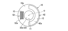
- FIGS. 4 to 6 are diagrams showing the configuration of the direct-view insertion section 10 that includes the illumination window 12, the projection window 13, and the like on the distal end surface 10a. As shown in FIGS. 4 to 6, there are various modes of arrangement of the components on the distal end surface 10 a of the insertion portion 10 of the endoscope apparatus 1.
- the objective optical system 32 is arranged on the central axis O of the insertion portion 10.
- the illumination window 12 is provided so as to surround the objective optical system 32 by a half circumference of the outer periphery of the objective optical system 32.
- the projection window 13 is disposed on the opposite side of the illumination window 12 with respect to the objective optical system 32. In such an arrangement, the area occupied by the illumination window 12 can be increased.
- the shape of the objective optical system 32 is generally a circle or a shape close to a circle.
- the illumination window 12 and the projection window 13 can be efficiently arranged at the distal end portion of the endoscope whose arrangement area is limited, and the distal end portion of the endoscope. It is easy to reduce the diameter. Furthermore, since the center of the endoscopic image coincides with the central axis O of the insertion unit 10, the operator can insert the endoscope without feeling uncomfortable while observing the image of the subject on the monitor.
- a pattern generation unit 55 is provided on the back side of the projection window 13.
- the pattern generation unit 55 is arranged such that a line pattern is positioned in a direction perpendicular to the arrangement direction of the projection window 13 and the objective optical system.
- a perpendicular distance from the center point of the objective optical system to the line pattern (hereinafter referred to as a base line length) is ensured as long as possible, and the arrangement relationship in which the arrangement interval between the projection window and the objective optical system is closest is established. It is composed. Since the measurement accuracy is improved as the baseline length is longer, according to the present modification, a three-dimensional shape can be measured with high accuracy even in an endoscope apparatus in which the insertion portion has a reduced diameter.
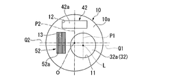
- the objective optical system 32 is arranged at a position decentered with respect to the central axis O of the insertion portion 10. As shown in FIG. 5, it is also possible to arrange the illumination windows 12 at two locations sandwiching the objective optical system 32 and the projection window 13 therebetween.
- the objective optical system 32 is arranged so that the optical axis on the emission side of reflected light in the observation field from the objective optical system 32 toward the imager 31 is parallel to the central axis O and decentered.
- the opening 11, the illumination window 12, and the projection window 13 in which the objective optical system 32 is disposed are decentered with respect to the central axis O of the insertion unit 10 on the distal end surface 10 a of the insertion unit 10. It may be arranged at the position. Further, the vertical axis P1 and the left and right axis Q1 passing through the optical axis L of the objective optical system 32 may be disposed at a position where the vertical axis P2 and the left and right axis Q2 passing through the central axis of the insertion portion 10 do not overlap.
- the objective optical system 32 is on the central axis O of the insertion unit 10.
- the insertion portion 10 can be further reduced in diameter.
- the first fiber bundle 43 is not provided, the light from the first light source 41 is directly irradiated toward the illumination window 12, the second fiber bundle 53 is not provided, and the first The light from the two light sources 51 is directly irradiated toward the stripe pattern generation unit 55.
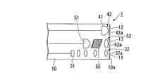
- the first light source 41, the second light source 51, and the imager 31 are provided in the vicinity of the distal end of the insertion portion 10, and the removable optical adapter 10 ⁇ / b> A is provided at the distal end portion of the insertion portion 10. It can also be.
- the optical adapter 10A accommodates the illumination window 12, the projection window 13, and a part of the objective optical system 32. Further, the distal end surface 10a1 of the optical adapter 10A corresponds to the distal end surface 10a of the insertion portion 10 in the first embodiment described above.
- the first light source 41 and the illumination window 12 are connected by an optical fiber 43A arranged in the optical adapter 10A.
- the second light source 51 and the pattern generation unit 55 are connected by an optical fiber 53A arranged in the optical adapter 10A.
- the first light source 41 and the second light source 51 are provided in the vicinity of the distal end of the insertion portion 10, when the insertion portion 10 has a length exceeding, for example, several tens of meters, the first fiber bundle 43 and the second fiber Light loss is less than when the bundle 53 is used, and a bright image can be acquired.
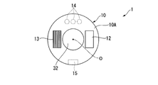
- FIG. 10 is a modified example of another arrangement obtained by further modifying the arrangement of FIG. This modification is an example of an endoscope apparatus having an optical adapter 10A.
- FIG. 10 shows a view of the tip surface of the optical adapter.
- the objective optical system 32 is disposed on the central axis O of the insertion unit 10, and the illumination window 12 and the projection window 13 are disposed on both sides of the objective optical system 32, respectively.
- a contact pin 14 for supplying power from the main body side to the first light source and the second light source is provided on the back side of the optical adapter 10A.
- a positioning groove 15 or an alternative structure is provided on the back side of the optical adapter 10A for positioning in the rotational direction with respect to the central axis of the insertion portion. It has been.
- Such contact pins 14 and positioning grooves 15 are respectively provided on the side where the illumination window 12 and the projection window 13 are not disposed with respect to the objective optical system 32. Thereby, even if it is an optical adapter type, the contact pin 14, the positioning groove 15, the illumination window 12, and the projection window 13 are arranged at the distal end portion of the small-diameter endoscope without interfering with each other. Can do.
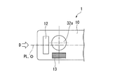
- FIG. 11 is a modification of the distal end portion in the endoscope apparatus that can observe a direction perpendicular to the central axis of the insertion portion.
- a distal end surface 10 b instead of the distal end surface 10 a, a distal end surface 10 b whose normal is a straight line perpendicular to the central axis of the insertion portion 10 is formed on a part of the outer peripheral surface of the distal end portion of the insertion portion 10.
- the illumination window 12, the projection window 13, and the cover member 32a are all disposed on the distal end surface 10b.
- the objective optical system 32 includes a prism 16 that directs the incident-side optical axis L1 in a direction intersecting the outgoing-side optical axis L2 from the objective optical system 32 toward the imager 31.
- the prism 16 is one of the optical elements constituting the objective optical system 32.
- the optical axis L1 on the incident side is an optical axis when the reflected light in the observation field enters the prism 16, and the optical axis L2 on the emission side reflects the reflected light in the observation field from the prism 16 to the imager 31. Is the optical axis when incident on the optical axis.
- the incident-side optical axis L ⁇ b> 1 is in a twisted position with respect to the central axis O of the insertion portion 10. Furthermore, the optical axis L2 on the emission side is parallel to the central axis O of the insertion portion 10.
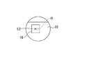
- FIG. 12A and 12B are views of the distal end surface 10b in the endoscope of FIG. 11 as viewed from a direction perpendicular to the distal end surface 10b, and are planes illustrating an arrangement example of the illumination window 12, the projection window 13, and the cover member 32a.
- FIG. 12A and 12B are views of the distal end surface 10b in the endoscope of FIG. 11 as viewed from a direction perpendicular to the distal end surface 10b, and are planes illustrating an arrangement example of the illumination window 12, the projection window 13, and the cover member 32a.
- the tip surface 10b is a substantially flat plane.
- the cover member 32a and the projection window 13 are arranged on the central axis O of the insertion portion 10 in plan view.
- the two illumination windows 12 are arranged on the side surface of the cover member 32a.
- Both the cover member 32a and the projection window 13 are exposed on the distal end surface 10b which is the outer peripheral surface of the distal end portion of the insertion portion.
- a line obtained by projecting the center axis O perpendicularly to the tip surface 10b is defined as a virtual center line PL. That is, in FIG.
- the cover member 32a and the projection window 13 are disposed at a position where their centers intersect with the virtual center line PL.
- the projection window 13 is a plane in which the center of the projection window when the projection window 13 is viewed from the thickness direction of the projection window 13 is defined by the central axis O of the insertion portion 10 and the optical axis L1 on the incident side. It is a positional relationship that exists within.
- the cover member 32a is arranged at a position where the center does not intersect with the virtual center line PL
- the illumination window 12 is arranged on the virtual center line PL of the insertion portion 10
- the projection window 13 further. May be arranged at a position where the center does not intersect with the virtual center line PL.
- FIGS. 12A and 12B are schematic views when the insertion portion 10 is viewed from the direction indicated by reference sign D in FIGS. 12A and 12B, respectively, and are front views of the insertion portion 10.
- the objective optical is set so that the optical axis L2 when the reflected light in the observation field enters the imager 31 from the prism 16 and the central axis O of the insertion portion 10 are decentered.
- a system 32 and an imager 31 are arranged.
- FIGS. 11 and 12A to 12D even in an example of an endoscope for observing the lateral direction, a case where projection windows 13 for projecting a light / dark pattern are provided at a plurality of positions as in the conventional case. In comparison, it is easy to reduce the diameter of the tip by having one projection window.
- positioned at a front end surface it is not restricted only to the example of FIG. 12A and FIG. 12B.
- the optical axis L1 and the optical axis L2 are orthogonal to each other is illustrated, but the optical axis L1 and the optical axis L2 may intersect at an angle other than orthogonal.
- the second light source 51 is provided on the distal end side of the insertion portion 10 as shown in FIG. 7, and is a high-luminance light source such as a laser.
- the second light source 51 is turned on while the first light source 41 is kept on based on a command from the main control unit 22, and an appropriate fringe is projected from one place onto the test object.
- the state that has been made may be referred to as a “stripe projection state”.
- the light amount is changed by controlling the second light source 51 without changing the phase of the light / dark pattern. Alternatively, stripe images with different stripe brightness may be taken.
- step S9 a bright field image captured before capturing N striped images and a bright field image captured after capturing N striped images are selected, and these The sum of the differences in luminance values between the two images is calculated. Further, in the above-described step S10, if the sum of the differences between the luminance values calculated in step S9 is smaller than the threshold value, it is determined that there is no blur between the first image and the subsequent image, and the process proceeds to step S11. move on. Conversely, if the sum of the differences between the brightness values calculated in step S9 is greater than the threshold value, it is determined that there is a blur between the first image and the subsequent image. Is displayed on the monitor 28 (step S14), and the series of processes is terminated.
- the above example is an example in which the difference is calculated over the entire image. Note that processing may be performed on only a part of the image. Alternatively, the luminance difference may be calculated using one bright field image and one striped image.
- the control operation by the main control unit 22 is different from that in the first embodiment and the first to ninth modifications.
- the second light source 51 (see FIG. 7) is composed of a plurality of minute light emitting elements. The plurality of light emitting elements provided in the second light source 51 are controlled to be turned on every two or more groups.
- the light / dark pattern generation unit 55 cannot change the stripe phase arbitrarily. It may be a board with, or something similar.
- step S5 a plurality of different stripes are projected onto the test object by sequentially switching the group of light emitting elements to be lit. Further, in step S6, each of these striped images can be taken.
- the first embodiment of the present invention has been described in detail with reference to the drawings. However, the specific configuration is not limited to this embodiment, and design changes and the like within the scope of the present invention are included. .
- a fringe image may be used as an image used for detecting blur. Absent.
- more than two bright field images can be taken. If there are more than two bright field images, the necessary number of images can be selected from these bright field images to detect blur. can do.
- the constituent elements shown in the first embodiment and the respective modifications can be combined as appropriate.
- FIG. 1 is a block diagram illustrating a configuration of an endoscope apparatus 1 according to the present embodiment.
- FIG. 2 is a schematic diagram showing a light / dark pattern projected by the endoscope apparatus 1. Note that the configuration of the endoscope apparatus of the second embodiment is the same as that of the endoscope apparatus of the first embodiment. Therefore, the same components as those in the first embodiment are denoted by the same reference numerals, and detailed description thereof is omitted.
- the measurement method of the second embodiment of the present invention will be described using an example in which measurement is performed using the endoscope apparatus 1 described above.
- the endoscope apparatus 1 when the endoscope apparatus 1 is used, first, the user uses the insertion portion 10 to access the test object such as the inside of the test object or a pipe line. The tip of the insertion portion 10 is advanced to a predetermined observation site. The user switches the observation mode for observing a desired part of the test object and the measurement mode for measuring the three-dimensional shape of the test part, as necessary, to inspect the test object.
- the light source control unit 21 controls the first light source 41 to be turned on and the second light source 51 to be turned off.
- the fringe pattern is not projected from the pattern projection unit 50, and the observation field is illuminated with white light from the illumination unit 40, and the observation field is illuminated (hereinafter, this illumination state is referred to as “observation state”).
- the illuminated image of the object is formed on the imager 31 through the objective optical system 32.
- the video signal sent from the imager 31 is processed by the video processor 27 and displayed on the monitor 28. The user can observe the test object from the image of the test object displayed on the monitor 28, and can store the image as necessary.
- the user When switching from the observation mode to the measurement mode, the user inputs an instruction to switch the mode.
- a known input device can be adopted as an input device for inputting an instruction for switching modes.
- a configuration in which a switch is provided in the operation unit 23 or a configuration in which the monitor 28 is changed to a touch panel to be a software switch can be employed.
- the main control unit 22 starts a measurement image photographing process (see FIG. 13).
- step S1 it is determined whether or not the endoscope apparatus 1 is in an observation state (step S1 shown in FIG. 13). If it is determined in step S1 that it is in the observation state, the process proceeds to step S3, and if it is in a state other than the observation state (for example, a measurement state described later) in step S1, the process proceeds to step S2. This ends step S1.
- Step S2 is a step of switching the endoscope apparatus 1 to the observation state.
- the first light source 41 is on-controlled and the second light source 51 is off-controlled.
- the pattern projection unit 50 does not project the fringe pattern, and the illumination unit 40 irradiates the observation field with white light, and the observation field is illuminated.
- Step S2 is complete
- Step S ⁇ b> 3 is a step of capturing an image of the test object that is not projected with the fringe pattern and is illuminated with white light from the illumination unit 40.
- step S ⁇ b> 3 an image is acquired by the imager 31 of the imaging unit 30 in a state where the test object is illuminated with white light from the illumination unit 40 (hereinafter, an image captured in the observation state is referred to as a “bright field image”). Called).
- the bright field image photographed in step S3 is temporarily stored in the RAM 24. Step S3 is completed now and it progresses to Step S16.
- Step S ⁇ b> 16 is a step of projecting a predetermined fringe pattern from one place of the endoscope apparatus 1 onto the test object.
- the first light source 41 is turned off and the second light source 51 is turned on based on a command from the main control unit 22.
- the white light irradiated from the illumination unit 40 is turned off, and the fringe pattern is projected from the pattern projection unit 50 onto the test object.
- the fringe pattern projected onto the test object is a pattern in which bright portions R ⁇ b> 1 due to a white light source and dark portions R ⁇ b> 2 shielded by the pattern generation unit 55 are alternately arranged. (Hereinafter, this state is referred to as a “pattern projection state”).
- Step S16 is ended now and it progresses to Step S17.
- Step S17 is a step of capturing a pattern projection image in the pattern projection state.
- the fringe pattern projected onto the test object is a pattern that changes according to the three-dimensional shape of the test object.
- one image is acquired by the imager 31 of the imaging unit 30 (hereinafter, an image photographed in the pattern projection state is referred to as a “pattern projection image”).
- the pattern projection image photographed in step S17 is temporarily stored in the RAM 24. Step S17 is ended now and it progresses to Step S18.
- Step S18 is a step of switching the endoscope apparatus 1 to the observation state.
- the first light source 41 is on-controlled and the second light source 51 is off-controlled.
- the pattern projection unit 50 does not project the fringe pattern, and the illumination unit 40 irradiates the observation field with white light, and the observation field is illuminated.
- Step S18 is completed now and it progresses to Step S19.
- Step S ⁇ b> 19 is a step of capturing an image of the test object that is not projected with the stripe pattern and is illuminated with white light from the illumination unit 40.
- step S ⁇ b> 19 a bright field image is captured by the imager 31 of the imaging unit 30 in a state where the test object is illuminated with white light from the illumination unit 40.
- the bright field image photographed in step S19 is temporarily stored in the RAM 24. Step S19 is completed now and it progresses to Step S20.
- step S20 relative movement between the insertion unit 10 and the test object between step S3 and step S19 is performed based on the images (bright field image and pattern projection image) taken between step S3 and step S19.
- images (bright field image and pattern projection image) taken between step S3 and step S19.
- blue the images taken between step S3 and step S19.
- step S20 first, two images are selected from at least one of the bright field image and the pattern projection image stored in the RAM 24. For example, in the second embodiment, a bright field image captured before capturing one pattern projection image and a bright field image captured after capturing one pattern projection image are selected. Subsequently, the same feature point is detected from the two selected images, and the coordinates of the feature point in the two images are calculated. Step S20 is ended now and it progresses to Step S21.
- Step S21 is a step of branching the processing by determining blurring of the two images using the feature points detected in step S20.
- step S21 if the coordinates of the feature points in the two images are the same in each image, it is determined that there is no blur between the first image and the subsequent image, and the process proceeds to step S22.
- step S25 if the coordinates of the feature points in the two images are different in each image, it is determined that there is a blur between the first image and the subsequent image, and a blur has occurred. Is displayed on the monitor 28 (step S25), and the series of processes is terminated. This ends step S21.
- Step S22 is a step in which the user selects whether to perform the three-dimensional measurement using the captured pattern projection image now or later.
- step S22 for example, an inquiry such as “Perform measurement?” Is displayed on the monitor 28, and the user is prompted to input whether or not to perform three-dimensional measurement using the captured pattern projection image. If there is an input that the measurement can be performed, the process proceeds to step S23. If there is an input that the measurement is not performed, the process proceeds to step S26. Step S22 is complete
- Step S23 is a step of performing analysis for performing three-dimensional measurement.
- the three-dimensional shape is analyzed based on the pattern projection image stored in the RAM 24.
- the three-dimensional shape of the test object is analyzed by using, for example, a known spatial phase shift method or Fourier transform method using one pattern projection image.
- the analysis result of the three-dimensional shape is generated as a text file or a binary file, and is stored in the auxiliary storage device 25 together with the pattern projection image.
- step S23 may be performed as the background process of step S22 simultaneously with the start of step S22. Step S23 is ended now and it progresses to Step S24.
- step S24 the display on the monitor 28 is shifted to the screen of various measurement modes, and the measurement result is displayed on the monitor 28 using the information stored in step S23.
- step S24 the test object displayed in the bright field image is overlaid on the bright field image acquired in step S3 (or the bright field image acquired in step S19) by overlaying the result analyzed in step S23.
- the three-dimensional shape is displayed on the monitor 28. Thereby, the user can know the three-dimensional shape of the test object.
- Step S24 is complete
- Step S26 is a step branched from step S22, and is a step for performing information processing necessary for displaying the measurement result later.
- the three-dimensional shape is analyzed based on the pattern projection image stored in the RAM 24, as in step S23.
- the three-dimensional shape of the test object is analyzed by the spatial phase shift method or the Fourier transform method using one pattern projection image.
- the bright field image, the pattern projection image, the analysis result of the three-dimensional shape, and the optical parameters used for the analysis are stored in the auxiliary storage device 25 as a binary file or a text file, respectively.
- Step S26 is complete
- the test object is based on one pattern projection image photographed in a state where a predetermined fringe pattern is projected onto the test object. Since the three-dimensional shape can be measured, the three-dimensional shape can be measured in a short time using the endoscope apparatus 1.
- the measurement method of the second embodiment of the present invention even in an environment in which a fringe pattern is projected from one projection window 13 in the endoscope apparatus 1 in which the insertion portion 10 is reduced in diameter, it is accurate. A three-dimensional shape can be measured.
- a bright-field image can be taken, and blur can be detected using two images selected from the pattern projection image and the bright-field image. Accuracy can be increased.
- blur is detected using bright field images before and after pattern projection images are taken, and when it is determined that there is no blur, a three-dimensional shape is analyzed.
- the analysis is not performed while the fringe patterns on the plurality of pattern projection images are shifted. For this reason, the analysis precision of a three-dimensional shape can be improved. Further, it is possible to suppress a positional deviation when the measurement result using the pattern projection image is displayed as an overlay on the bright field image.
- the method for measuring the three-dimensional shape of the test object is different.
- the measurement method of the present modification will be described focusing on the point of difference in processing content from the above-described second embodiment.
- step S23 and step S26 a three-dimensional shape is analyzed by a light cutting method using one pattern projection image.
- a three-dimensional shape is analyzed on a single pattern using a single pattern projection image. Therefore, compared to the case where the entire surface of one pattern projection image is analyzed in the above-described embodiment, the portion where the three-dimensional shape can be measured is limited, but the analysis time can be greatly shortened.
- the second embodiment of the present invention has been described in detail with reference to the drawings. However, the specific configuration is not limited to this embodiment, and design changes and the like within a scope not departing from the gist of the present invention are included. .
- an example of capturing one pattern projection image has been described. However, a plurality of pattern projection images are captured, and one pattern projection image with a good image state is captured. By selecting, substantially one pattern projection image may be acquired and used for analysis.
- a pattern projection image may be used as an image used for detecting blur. I do not care. Also, more than two bright field images can be taken. If there are more than two bright field images, the necessary number of images can be selected from these bright field images to detect blur. can do.
- the diameter of the insertion portion can be reduced.
- a three-dimensional shape can be measured with high accuracy even in an endoscope apparatus in which the insertion portion has a reduced diameter.
- the three-dimensional shape measurement method of the endoscope apparatus the three-dimensional shape can be measured by analyzing one striped image photographed using the endoscope apparatus. The three-dimensional shape can be measured in a short time using the endoscope apparatus.
Landscapes
- Health & Medical Sciences (AREA)
- Life Sciences & Earth Sciences (AREA)
- Physics & Mathematics (AREA)
- Surgery (AREA)
- Engineering & Computer Science (AREA)
- Biomedical Technology (AREA)
- Biophysics (AREA)
- Public Health (AREA)
- Pathology (AREA)
- General Health & Medical Sciences (AREA)
- Veterinary Medicine (AREA)
- Animal Behavior & Ethology (AREA)
- Heart & Thoracic Surgery (AREA)
- Medical Informatics (AREA)
- Molecular Biology (AREA)
- Optics & Photonics (AREA)
- Nuclear Medicine, Radiotherapy & Molecular Imaging (AREA)
- Radiology & Medical Imaging (AREA)
- General Physics & Mathematics (AREA)
- Dentistry (AREA)
- Oral & Maxillofacial Surgery (AREA)
- Astronomy & Astrophysics (AREA)
- Signal Processing (AREA)
- Computer Vision & Pattern Recognition (AREA)
- Theoretical Computer Science (AREA)
- Multimedia (AREA)
- Endoscopes (AREA)
- Instruments For Viewing The Inside Of Hollow Bodies (AREA)
Abstract
The endoscopic device and measurement method perform measurements on subjects using pattern projection images in which a fringe pattern is projected on the subject. Said endoscopic device is equipped with: a long insertion part (10); an image pickup part (30), which is provided on the tip of the insertion part (10) and acquires images of the subject; an illumination part (40) which is provided on the tip of the insertion part (10) and generates illumination light that illuminates the field of vision of the image pickup part (30); and a pattern-projecting part (50), which is provided on the tip of the insertion part (10) and projects a fringe pattern on the subject. The surface of the tip (10a) of the insertion part (10) is provided with an objective optical system (32) that forms images of the subject on the image pickup part (30), one or more illumination windows (12) that emit the illumination light, and one projection window (13) that projects the fringe pattern from the pattern-projecting part (50) onto the subject.
Description
本発明は、内視鏡装置および計測方法、より詳しくは、被検物に縞等のパターンを投影して被検物表面の三次元形状を計測する内視鏡装置、および被検物に縞等のパターンを投影して被検物表面の三次元形状を計測する方法に関する。
本願は、2011年04月27日に、日本に出願された特願2011-099889号と、2011年04月27日に、日本に出願された特願2011-099890号と、に基づき優先権を主張し、その内容をここに援用する。 The present invention relates to an endoscope apparatus and a measuring method, and more specifically, an endoscope apparatus that measures a three-dimensional shape of a surface of a test object by projecting a pattern such as a stripe on the test object, and a streak on the test object. The present invention relates to a method for measuring the three-dimensional shape of the surface of a test object by projecting a pattern such as the above.
This application has priority based on Japanese Patent Application No. 2011-099889 filed in Japan on April 27, 2011 and Japanese Patent Application No. 2011-099890 filed on April 27, 2011 in Japan. Insist and use that content here.
従来、被検物を検査するために、長尺の挿入部を備え、挿入部の先端に光学系や撮像素子等の観察手段を有する内視鏡(内視鏡装置)が使用されている。このような内視鏡の中には、被検物に対して縞を投影した縞画像を、当該縞の位相をずらしつつ複数取得し、これら複数の縞画像を用いた公知の位相シフト法により被検物の三次元形状を算出するものが知られている。例えば、特許文献1には、縞を投影するための2つの投影窓が挿入部の先端面に設けられた内視鏡装置が記載されている。
Conventionally, in order to inspect a test object, an endoscope (endoscope device) having a long insertion portion and having observation means such as an optical system and an image sensor at the tip of the insertion portion is used. In such an endoscope, a plurality of fringe images obtained by projecting fringes on the test object are obtained while shifting the phase of the fringes, and a known phase shift method using the plurality of fringe images is used. What calculates the three-dimensional shape of a test object is known. For example, Patent Document 1 describes an endoscope apparatus in which two projection windows for projecting stripes are provided on the distal end surface of an insertion portion.
しかしながら、特許文献1に記載の内視鏡装置では、縞投影用の光源から外部へ光を出射するための窓が、内視鏡装置の挿入部の先端面の2箇所に設けられているので、内視鏡装置の挿入部を細径化するのに限界があった。
また、特許文献1に記載の内視鏡装置では、縞の位相をずらしつつ複数の縞画像を取得し、複数の縞画像を解析することによって計測を行うので、計測に要する時間が長いという課題があった。 However, in the endoscope apparatus described inPatent Document 1, windows for emitting light from the fringe projection light source to the outside are provided at two positions on the distal end surface of the insertion portion of the endoscope apparatus. There is a limit to reducing the diameter of the insertion portion of the endoscope apparatus.
Moreover, in the endoscope apparatus described inPatent Document 1, a plurality of fringe images are acquired while shifting the phase of the fringes, and the measurement is performed by analyzing the plurality of fringe images. was there.
また、特許文献1に記載の内視鏡装置では、縞の位相をずらしつつ複数の縞画像を取得し、複数の縞画像を解析することによって計測を行うので、計測に要する時間が長いという課題があった。 However, in the endoscope apparatus described in
Moreover, in the endoscope apparatus described in
本発明は、挿入部が細径化された内視鏡装置を提供することを目的とする。また、挿入部が細径化された内視鏡装置であっても精度良く三次元形状を計測できる計測方法を提供することを目的とする。
さらに、内視鏡装置を用いて三次元形状の計測を短時間で行う計測方法を提供することを目的とする。 An object of the present invention is to provide an endoscope apparatus in which an insertion portion is reduced in diameter. It is another object of the present invention to provide a measurement method that can accurately measure a three-dimensional shape even in an endoscope apparatus in which an insertion portion has a reduced diameter.
Furthermore, it aims at providing the measuring method which measures a three-dimensional shape in a short time using an endoscope apparatus.
上記課題を解決するために、この発明は以下の手段を提案している。
本発明の第一の態様に係る内視鏡装置は、光の明暗パターンが投影された被検物のパターン投影画像を用いて前記被検物の計測を行う内視鏡装置である。本発明の第一の態様に係る内視鏡装置は、挿入部と、撮像部と、照明部と、パターン投影部と、を備える。前記撮像部は、前記挿入部の先端部に設けられ、前記被検物の画像を取得する。前記照明部は、前記撮像部の観察視野を照明する照明光を発する。前記パターン投影部は、前記被検物に前記明暗パターンを投影する。前記挿入部の先端面には、前記撮像部に前記被検物の像を結像させる対物光学系と、前記照明光を出射する1つ以上の照明窓と、前記パターン投影部から前記被検物へ前記明暗パターンを投影する1つの投影窓と、が設けられる。 In order to solve the above problems, the present invention proposes the following means.
The endoscope apparatus according to the first aspect of the present invention is an endoscope apparatus that performs measurement of the test object using a pattern projection image of the test object on which a light brightness / darkness pattern is projected. An endoscope apparatus according to a first aspect of the present invention includes an insertion unit, an imaging unit, an illumination unit, and a pattern projection unit. The imaging unit is provided at a distal end of the insertion unit and acquires an image of the test object. The illumination unit emits illumination light that illuminates the observation field of view of the imaging unit. The pattern projection unit projects the light and dark pattern onto the test object. An objective optical system that forms an image of the test object on the imaging unit, one or more illumination windows that emit the illumination light, and the test object from the pattern projection unit are provided on the distal end surface of the insertion unit. A projection window for projecting the light and dark pattern onto an object.
また、本発明の第二の態様によれば、前記対物光学系は、前記対物光学系の光軸のうち前記対物光学系から前記撮像部に向かう出射側の光軸が、前記挿入部の中心軸線に対して平行かつ偏心するように配置される。
Further, according to the second aspect of the present invention, the objective optical system has an optical axis on the emission side from the objective optical system to the imaging unit among the optical axes of the objective optical system, the center of the insertion unit. It arrange | positions so that it may be parallel and eccentric with respect to an axis.
また、本発明の第三の態様によれば、前記対物光学系は入射側の光軸と出射側の光軸とがともに前記中心軸線と平行な直視型対物光学系である。さらに、前記対物光学系は、前記挿入部の先端部の先端面に設けられ、前記中心軸線に対して偏心した位置に配置される。
Further, according to the third aspect of the present invention, the objective optical system is a direct-view objective optical system in which both the incident-side optical axis and the outgoing-side optical axis are parallel to the central axis. Furthermore, the objective optical system is provided on a distal end surface of the distal end portion of the insertion portion, and is disposed at a position decentered with respect to the central axis.
また、本発明の第四の態様によれば、前記投影窓は、前記先端面に設けられ、前記挿入部の中心軸線に対して偏心した位置に配置される。
Further, according to the fourth aspect of the present invention, the projection window is provided on the distal end surface, and is disposed at a position eccentric with respect to the central axis of the insertion portion.
また、本発明の第五の態様によれば、前記対物光学系は、前記挿入部の先端部の外周面に露出され、入射側の光軸が前記中心軸線に対してねじれの位置に配置された側視型対物光学系である。
According to the fifth aspect of the present invention, the objective optical system is exposed on the outer peripheral surface of the distal end portion of the insertion portion, and the optical axis on the incident side is arranged at a position twisted with respect to the central axis. This is a side view type objective optical system.
また、本発明の第六の態様によれば、前記投影窓は、前記挿入部の先端部の外周面に露出され、前記投影窓の厚さ方向から前記投影窓を見たときの前記投影窓の中心を通り前記投影窓の厚さ方向に延びる中心線は、前記挿入部の中心軸線に対してねじれの位置に配置される。
According to the sixth aspect of the present invention, the projection window is exposed on the outer peripheral surface of the distal end portion of the insertion portion, and the projection window is viewed from the thickness direction of the projection window. A center line that passes through the center of the projection window and extends in the thickness direction of the projection window is disposed at a twisted position with respect to the center axis of the insertion portion.
また、本発明の第七の態様によれば、前記対物光学系は、前記挿入部の先端部の外周面に露出され、入射側の光軸が前記挿入部の中心軸線に対して交差して配置された側視型対物光学系である。さらに、前記投影窓は、前記投影窓の厚さ方向から前記投影窓を見たときの前記投影窓の中心が、前記挿入部の中心軸線と前記入射側の光軸とによって規定される平面内に存するように前記挿入部の先端部の外周面に配置される。
According to the seventh aspect of the present invention, the objective optical system is exposed on the outer peripheral surface of the distal end portion of the insertion portion, and the optical axis on the incident side intersects the central axis of the insertion portion. This is a side-viewing objective optical system. Further, the projection window has a plane in which the center of the projection window when the projection window is viewed from the thickness direction of the projection window is defined by the central axis of the insertion portion and the optical axis on the incident side. As described above, the insertion portion is disposed on the outer peripheral surface of the distal end portion.
また、本発明の第八の態様によれば、前記パターン投影部は、ライン状の1本以上の平行するパターンを有する。
Also, according to the eighth aspect of the present invention, the pattern projection unit has one or more line-shaped parallel patterns.
また、本発明の第九の態様によれば、前記パターン投影部は、投影用光源と、前記投影用光源から出射される光の強度分布を変更し、前記明暗パターンを生成するパターン生成部とを備える。
According to a ninth aspect of the present invention, the pattern projection unit includes a projection light source, a pattern generation unit that changes the intensity distribution of the light emitted from the projection light source, and generates the light-dark pattern. Is provided.
また、本発明の第十の態様によれば、内視鏡装置は、前記投影用光源から出射される光を前記パターン生成部に導く光ファイバーを備える。さらに、前記投影用光源は、前記挿入部の基端側に設けられ、前記パターン生成部は、前記挿入部の先端部に設けられる。
Also, according to the tenth aspect of the present invention, the endoscope apparatus includes an optical fiber that guides light emitted from the projection light source to the pattern generation unit. Further, the projection light source is provided on a proximal end side of the insertion portion, and the pattern generation portion is provided on a distal end portion of the insertion portion.
また、本発明の第十一の態様によれば、前記投影用光源及び前記パターン生成部は、前記挿入部の先端部に設けられる。
Further, according to the eleventh aspect of the present invention, the projection light source and the pattern generation unit are provided at a distal end of the insertion unit.
また、本発明の第十二の態様によれば、内視鏡装置は、前記投影用光源から出射され、前記パターン生成部によって生成された前記明暗パターンを前記挿入部の先端側まで導く光ファイバーを備える。さらに、前記投影用光源及び前記パターン生成部は、前記挿入部の基端側に設けられる。
According to a twelfth aspect of the present invention, the endoscope apparatus includes an optical fiber that is emitted from the projection light source and guides the light / dark pattern generated by the pattern generation unit to a distal end side of the insertion unit. Prepare. Further, the projection light source and the pattern generation unit are provided on the proximal end side of the insertion unit.
また、本発明の第十三の態様によれば、内視鏡装置は、前記挿入部の先端部に着脱自在に装着可能な光学アダプタを備え、前記パターン生成部は、前記光学アダプタに設けられる。
According to a thirteenth aspect of the present invention, the endoscope apparatus includes an optical adapter that can be detachably attached to a distal end portion of the insertion portion, and the pattern generation portion is provided in the optical adapter. .
また、本発明の第十四の態様によれば、前記投影用光源は、前記光学アダプタに設けられる。
According to the fourteenth aspect of the present invention, the projection light source is provided in the optical adapter.
また、本発明の第十五の態様によれば、内視鏡装置は、前記明暗パターンを投影するための光と前記照明光とを切り替える切り替え手段を備える。
Also, according to the fifteenth aspect of the present invention, the endoscope apparatus includes switching means for switching between the light for projecting the bright and dark pattern and the illumination light.
本発明の第十六の態様に係る計測方法は、被検物の三次元形状を内視鏡(内視鏡装置)を用いて計測する計測方法である。本発明の第十六の態様に係る計測方法は、所定の明暗パターンを前記内視鏡の一箇所から前記被検物に投影し、前記被検物において前記明暗パターンが投影された部分を撮像して少なくとも1枚のパターン投影画像を取得し、前記明暗パターンが投影された部分の三次元形状を前記パターン投影画像を用いて計測する。
The measurement method according to the sixteenth aspect of the present invention is a measurement method for measuring the three-dimensional shape of a test object using an endoscope (endoscope device). In the measurement method according to the sixteenth aspect of the present invention, a predetermined light / dark pattern is projected onto the test object from one place of the endoscope, and a portion of the test object on which the light / dark pattern is projected is imaged. Then, at least one pattern projection image is acquired, and the three-dimensional shape of the portion on which the light and dark pattern is projected is measured using the pattern projection image.
本発明の第十七の態様に係る計測方法は、被検物の三次元形状を内視鏡装置を用いて計測する計測方法である。本発明の第十七の態様に係る計測方法は、所定の縞パターンを前記内視鏡装置の1箇所から前記被検物に投影し、前記被検物において前記縞パターンが投影された部分を撮像して1枚の縞画像を取得し、空間的位相シフト法またはフーリエ変換法を用いて前記縞パターンが投影された部分の三次元形状を前記1枚の縞画像から計測する。
The measurement method according to the seventeenth aspect of the present invention is a measurement method for measuring a three-dimensional shape of a test object using an endoscope apparatus. In the measurement method according to the seventeenth aspect of the present invention, a predetermined fringe pattern is projected onto the test object from one location of the endoscope apparatus, and a portion of the test object on which the fringe pattern is projected is projected. An image is captured to obtain a single fringe image, and the three-dimensional shape of the portion onto which the fringe pattern is projected is measured from the single fringe image using a spatial phase shift method or a Fourier transform method.
また、本発明の第十八の態様によれば、計測方法は、前記1枚の縞画像を取得する前と後との少なくともいずれかに、前記縞パターンが投影される部分の明視野画像を少なくとも1枚取得し、前記1枚の縞画像および前記明視野画像から少なくとも2枚の画像を選択し、前記2枚の画像において所定量以上の位置ずれがある場合に前記内視鏡装置の位置がずれたことを検出する。
Further, according to the eighteenth aspect of the present invention, there is provided a measuring method comprising: obtaining a bright field image of a portion onto which the fringe pattern is projected at least before or after obtaining the one fringe image. The position of the endoscope apparatus when at least one image is acquired, at least two images are selected from the one stripe image and the bright field image, and the two images have a positional deviation of a predetermined amount or more. It is detected that the shift has occurred.
また、本発明の第十九の態様によれば、計測方法は、前記1枚の縞画像を取得する前および後に前記明視野画像を少なくとも1枚ずつ取得する。
Further, according to the nineteenth aspect of the present invention, the measurement method acquires at least one bright field image before and after acquiring the one striped image.
また、本発明の第二十の態様によれば、計測方法は、前記内視鏡装置の位置がずれたことを検出するために選択される少なくとも2枚の画像は、前記明視野画像から選択される。
According to the twentieth aspect of the present invention, in the measurement method, at least two images selected for detecting that the position of the endoscope device has shifted are selected from the bright field images. Is done.
本発明の態様に係る内視鏡装置によれば、挿入部を細径化することができる。
また、本発明の態様に係る計測方法によれば、挿入部が細径化された内視鏡装置であっても精度良く三次元形状を計測することができる。 According to the endoscope apparatus according to the aspect of the present invention, the diameter of the insertion portion can be reduced.
In addition, according to the measurement method according to the aspect of the present invention, it is possible to accurately measure a three-dimensional shape even in an endoscope apparatus in which the insertion portion has a reduced diameter.
また、本発明の態様に係る三次元形状の計測方法によれば、内視鏡装置を用いて撮影された1枚の縞画像を解析することによって三次元形状を計測することができるので、内視鏡装置を用いて三次元形状の計測を短時間で行うことができる。
Further, according to the three-dimensional shape measuring method according to the aspect of the present invention, the three-dimensional shape can be measured by analyzing one striped image photographed using the endoscope apparatus. The three-dimensional shape can be measured in a short time using the endoscope apparatus.
(第一実施形態)
以下、本発明の第一実施形態の内視鏡装置1および計測方法について説明する。
まず、本実施形態の内視鏡装置1の構成について説明する。図1は、本実施形態の内視鏡装置1の構成を示すブロック図である。図2は、内視鏡装置1によって投影される明暗パターンを示す模式図である。
内視鏡装置1は、被検物の内部観察や、通常の観察装置がアクセス困難な位置にある被検物の観察などに使用される。内視鏡装置1は、長尺の挿入部10と、挿入部10の基端が接続された本体部20とを備える。 (First embodiment)
Hereinafter, theendoscope apparatus 1 and the measurement method according to the first embodiment of the present invention will be described.
First, the configuration of theendoscope apparatus 1 according to the present embodiment will be described. FIG. 1 is a block diagram illustrating a configuration of an endoscope apparatus 1 according to the present embodiment. FIG. 2 is a schematic diagram showing a light / dark pattern projected by the endoscope apparatus 1.
Theendoscope apparatus 1 is used for internal observation of a test object, observation of a test object at a position where a normal observation apparatus is difficult to access, and the like. The endoscope apparatus 1 includes a long insertion portion 10 and a main body portion 20 to which a proximal end of the insertion portion 10 is connected.
以下、本発明の第一実施形態の内視鏡装置1および計測方法について説明する。
まず、本実施形態の内視鏡装置1の構成について説明する。図1は、本実施形態の内視鏡装置1の構成を示すブロック図である。図2は、内視鏡装置1によって投影される明暗パターンを示す模式図である。
内視鏡装置1は、被検物の内部観察や、通常の観察装置がアクセス困難な位置にある被検物の観察などに使用される。内視鏡装置1は、長尺の挿入部10と、挿入部10の基端が接続された本体部20とを備える。 (First embodiment)
Hereinafter, the
First, the configuration of the
The
図1に示すように、挿入部10は、管状に形成されており、被検物の内部または被検物へのアクセス経路に挿入される。挿入部10には、被検物の画像を取得する撮像部30と、挿入部10前方の観察視野を照明する照明部40と、被検物に明暗パターンを投影するパターン投影部50とが設けられている。本実施形態では、パターン投影部50は明暗パターンとして、縞パターンを被検物に投影する。
また、挿入部10の先端面10aには、撮像部30の対物光学系32に外光を入射させるための開口11と、照明部40からの照明光を挿入部の前方に照射するための照明窓12と、パターン投影部50からの縞を挿入部の前方に照射するための投影窓13とが設けられている。 As shown in FIG. 1, theinsertion part 10 is formed in a tubular shape, and is inserted into the inside of the test object or an access path to the test object. The insertion unit 10 includes an imaging unit 30 that acquires an image of the test object, an illumination unit 40 that illuminates the observation field of view in front of the insertion unit 10, and a pattern projection unit 50 that projects a light / dark pattern onto the test object. It has been. In the present embodiment, the pattern projection unit 50 projects a fringe pattern onto the test object as a bright and dark pattern.
In addition, thedistal end surface 10a of the insertion unit 10 is provided with an opening 11 for allowing external light to enter the objective optical system 32 of the imaging unit 30, and illumination for irradiating illumination light from the illumination unit 40 forward of the insertion unit. A window 12 and a projection window 13 for irradiating the stripes from the pattern projection unit 50 in front of the insertion unit are provided.
また、挿入部10の先端面10aには、撮像部30の対物光学系32に外光を入射させるための開口11と、照明部40からの照明光を挿入部の前方に照射するための照明窓12と、パターン投影部50からの縞を挿入部の前方に照射するための投影窓13とが設けられている。 As shown in FIG. 1, the
In addition, the
撮像部30は、挿入部10の先端付近に配置されたイメージャー31と、イメージャー31の前方に配置された対物光学系32と、イメージャー31と接続されたイメージャー制御部33とを備える。
The imaging unit 30 includes an imager 31 disposed near the distal end of the insertion unit 10, an objective optical system 32 disposed in front of the imager 31, and an imager control unit 33 connected to the imager 31. .
イメージャー31としては、CCD、CMOS等の各種イメージセンサを含む公知の各種構成を適宜選択して用いることができる。
As the imager 31, various known configurations including various image sensors such as a CCD and a CMOS can be appropriately selected and used.
対物光学系32は、挿入部10の開口11内に配置されている。所定の画角を有し、当該画角により規定される観察視野内の反射光をイメージャー31に入射させ、被検物の像を結像させる。また、対物光学系32は、開口11を封止する光透過性のカバー部材32aを有する。
The objective optical system 32 is disposed in the opening 11 of the insertion portion 10. Reflected light within an observation field having a predetermined field angle and defined by the field angle is incident on the imager 31 to form an image of the test object. The objective optical system 32 includes a light transmissive cover member 32 a that seals the opening 11.
イメージャー制御部33は、本体部20内に設けられており、挿入部10内を延びる配線34によりイメージャー31と接続されている。イメージャー制御部33は、イメージャー31の駆動および映像信号を取得する設定等の各種制御を行う。
The imager control unit 33 is provided in the main body unit 20 and is connected to the imager 31 by a wiring 34 extending in the insertion unit 10. The imager control unit 33 performs various controls such as driving of the imager 31 and setting for acquiring a video signal.
照明部40は、第一光源41と、照明光学系42と、第一光源41の光を照明光学系42に導く第一ファイバーバンドル43と、第一光源41と第一ファイバーバンドル43との間に配置される第一入射光学系44とを備える。
The illumination unit 40 includes a first light source 41, an illumination optical system 42, a first fiber bundle 43 that guides light from the first light source 41 to the illumination optical system 42, and between the first light source 41 and the first fiber bundle 43. And a first incident optical system 44.
第一光源41は、一般的な白色光源であり、本体部20の内部に配置されている。第一光源41としては、LEDやレーザーなどの発光素子や、ハロゲンランプ等を採用することができる。
The first light source 41 is a general white light source and is disposed inside the main body 20. As the first light source 41, a light emitting element such as an LED or a laser, a halogen lamp, or the like can be employed.
照明光学系42は、挿入部10の先端または先端付近に取り付けられている。照明光学系42は、挿入部10の照明窓12内に設けられた光透過性のカバー部材42aと、図示しないレンズ群とを有する。照明光学系42は、第一光源41から照射された光を対物光学系32の画角に適した視野範囲に広げて照明窓12から出射させ、観察視野をくまなく照明する。
The illumination optical system 42 is attached at or near the distal end of the insertion portion 10. The illumination optical system 42 includes a light transmissive cover member 42 a provided in the illumination window 12 of the insertion unit 10 and a lens group (not shown). The illumination optical system 42 spreads the light emitted from the first light source 41 in the field of view suitable for the angle of view of the objective optical system 32 and emits it from the illumination window 12 to illuminate the entire observation field.
第一ファイバーバンドル43は、照明光学系42の近傍から挿入部10を通って本体部20内の第一光源41近傍まで延びている。第一ファイバーバンドル43の種類には特に制限はなく、一般的なライトガイドを使用可能である。
The first fiber bundle 43 extends from the vicinity of the illumination optical system 42 to the vicinity of the first light source 41 in the main body 20 through the insertion portion 10. There is no restriction | limiting in particular in the kind of 1st fiber bundle 43, A general light guide can be used.
第一入射光学系44は、第一光源41から発せられる光を第一ファイバーバンドル43の径と同程度まで収束させて効率よく第一ファイバーバンドル43内に導入する。
The first incident optical system 44 converges the light emitted from the first light source 41 to the same extent as the diameter of the first fiber bundle 43 and efficiently introduces it into the first fiber bundle 43.
パターン投影部50は、第二光源51(投影用光源)と、投影光学系52と、第二光源51の光を投影光学系52に導く第二ファイバーバンドル53と、第二光源51と第二ファイバーバンドル53との間に配置される第二入射光学系54と、第二光源51から出射された光の光路上に配置されたパターン生成部55とを備える。
The pattern projection unit 50 includes a second light source 51 (projection light source), a projection optical system 52, a second fiber bundle 53 that guides light from the second light source 51 to the projection optical system 52, a second light source 51, and a second light source 51. A second incident optical system 54 disposed between the fiber bundle 53 and a pattern generation unit 55 disposed on the optical path of the light emitted from the second light source 51 is provided.
第二光源51は、第一光源41と同様の白色光源であり、本体部20の内部に配置されている。なお、第二光源51は、第一光源41と波長が異なる光を発する光源であってもよい。
The second light source 51 is a white light source similar to the first light source 41 and is disposed inside the main body 20. The second light source 51 may be a light source that emits light having a wavelength different from that of the first light source 41.
投影光学系52は、挿入部10の先端または先端付近に取り付けられている。投影光学系52は、挿入部10の投影窓13内に設けられた光透過性のカバー部材52aを有する。なお、投影窓13に設けられたカバー部材52aはレンズ形状であっても構わない。投影光学系52は、第二光源51から照射された光を、対物光学系32の画角に適した視野範囲に広げて1つの投影窓13から観察視野内に投影する。
The projection optical system 52 is attached at or near the distal end of the insertion portion 10. The projection optical system 52 includes a light transmissive cover member 52 a provided in the projection window 13 of the insertion unit 10. Note that the cover member 52a provided in the projection window 13 may have a lens shape. The projection optical system 52 projects the light emitted from the second light source 51 into a field of view suitable for the angle of view of the objective optical system 32 and projects it from one projection window 13 into the observation field.
第二ファイバーバンドル53は、投影光学系52の近傍から挿入部10を通って本体部20内の第二光源51近傍まで延びている。第二ファイバーバンドル53としては、第一ファイバーバンドル43と同様に一般的なライトガイドを使用することができる。
The second fiber bundle 53 extends from the vicinity of the projection optical system 52 through the insertion section 10 to the vicinity of the second light source 51 in the main body section 20. As the second fiber bundle 53, a general light guide can be used similarly to the first fiber bundle 43.
第二入射光学系54は、第二光源51から発せられた光を、第二ファイバーバンドル53の径と同程度まで収束させて効率よく第二ファイバーバンドル53内に導入する。
The second incident optical system 54 converges the light emitted from the second light source 51 to the same extent as the diameter of the second fiber bundle 53 and efficiently introduces it into the second fiber bundle 53.
パターン生成部55は、位相がずれた複数の縞パターンを形成可能な公知の構成を用いることができる。例えば、複数のスリットを有するスリット板をアクチュエータで移動させる構成や、互いに位相のずれた複数の縞パターンが描かれたガラスや樹脂等からなる透明な板をアクチュエータで移動させる構成が、用いられる。
The pattern generation unit 55 can use a known configuration that can form a plurality of fringe patterns out of phase. For example, a configuration in which a slit plate having a plurality of slits is moved by an actuator, or a transparent plate made of glass, resin, or the like on which a plurality of fringe patterns whose phases are shifted from each other is moved by an actuator is used.
このほか、素子ごとに光の透過と不透過を切り替え可能な液晶シャッターモジュールや、素子ごとに微細な反射ミラーを備えるMEMS(マイクロ電子機器システム)ミラーモジュール等がパターン生成部55として用いられてもよい。この場合、素子ごとの制御を行うので、パターン生成部55全体を移動させずに位相がずれた複数の縞パターンを形成することができる。そのため、パターン投影部50の構成を簡素にすることができる利点がある。縞パターンの切り替えは、パターン生成部55に接続されたパターン制御部56によって行われる。
また、明暗パターンの形状としては、縞パターンに限らず、図2に示すようなライン状の複数の平行する線でもよい。また、その他の例としては、例えば、図9に示すような1本の線(後述)でもよい。また、複数の点や、複数の縦線と横線が交差した格子状のパターン、あるいは同心円状のパターンなどであってもよい。 In addition, a liquid crystal shutter module that can switch between transmission and non-transmission of light for each element, a MEMS (microelectronic device system) mirror module that includes a fine reflection mirror for each element, and the like may be used as thepattern generation unit 55. Good. In this case, since the control is performed for each element, a plurality of fringe patterns whose phases are shifted can be formed without moving the entire pattern generation unit 55. Therefore, there is an advantage that the configuration of the pattern projection unit 50 can be simplified. The fringe pattern is switched by the pattern control unit 56 connected to the pattern generation unit 55.
Further, the shape of the light / dark pattern is not limited to the stripe pattern, and may be a plurality of line-like parallel lines as shown in FIG. As another example, for example, a single line (described later) as shown in FIG. 9 may be used. Further, it may be a plurality of points, a lattice pattern in which a plurality of vertical lines and horizontal lines intersect, or a concentric pattern.
また、明暗パターンの形状としては、縞パターンに限らず、図2に示すようなライン状の複数の平行する線でもよい。また、その他の例としては、例えば、図9に示すような1本の線(後述)でもよい。また、複数の点や、複数の縦線と横線が交差した格子状のパターン、あるいは同心円状のパターンなどであってもよい。 In addition, a liquid crystal shutter module that can switch between transmission and non-transmission of light for each element, a MEMS (microelectronic device system) mirror module that includes a fine reflection mirror for each element, and the like may be used as the
Further, the shape of the light / dark pattern is not limited to the stripe pattern, and may be a plurality of line-like parallel lines as shown in FIG. As another example, for example, a single line (described later) as shown in FIG. 9 may be used. Further, it may be a plurality of points, a lattice pattern in which a plurality of vertical lines and horizontal lines intersect, or a concentric pattern.
本体部20内に設けられた他の機構について説明する。第一光源41および第二光源51は、これらの光源のオン/オフを制御する光源制御部21に接続されている。イメージャー制御部33、パターン制御部56、および光源制御部21は、内視鏡装置1全体の制御を行うメイン制御部22に接続されている。メイン制御部22には、使用者が内視鏡装置1に各種入力を行うための操作部23が接続されている。また、メイン制御部22は、主記憶装置(RAM24)と接続されている。また、本実施形態では、たとえば書き換え可能な不揮発メモリを有する記憶装置や磁気記憶装置などの補助記憶装置25がメイン制御部22に電気的に接続されている。
なお、必要に応じて、ファームウェア等を記録したROM26(あるいはEPROMやEEPROMなど)がメイン制御部22に接続されていてもよい。 Other mechanisms provided in themain body 20 will be described. The 1st light source 41 and the 2nd light source 51 are connected to the light source control part 21 which controls on / off of these light sources. The imager control unit 33, the pattern control unit 56, and the light source control unit 21 are connected to a main control unit 22 that controls the entire endoscope apparatus 1. The main control unit 22 is connected to an operation unit 23 for a user to make various inputs to the endoscope apparatus 1. The main control unit 22 is connected to a main storage device (RAM 24). In the present embodiment, for example, an auxiliary storage device 25 such as a storage device having a rewritable nonvolatile memory or a magnetic storage device is electrically connected to the main control unit 22.
Note that a ROM 26 (or EPROM, EEPROM, or the like) that records firmware or the like may be connected to themain control unit 22 as necessary.
なお、必要に応じて、ファームウェア等を記録したROM26(あるいはEPROMやEEPROMなど)がメイン制御部22に接続されていてもよい。 Other mechanisms provided in the
Note that a ROM 26 (or EPROM, EEPROM, or the like) that records firmware or the like may be connected to the
さらに、イメージャー31の取得した映像信号を処理するビデオプロセッサー27は、イメージャー制御部33およびメイン制御部22に接続されている。ビデオプロセッサー27によって処理された映像信号を画像として表示するモニター28は、ビデオプロセッサー27に接続されている。
Furthermore, the video processor 27 that processes the video signal acquired by the imager 31 is connected to the imager control unit 33 and the main control unit 22. A monitor 28 that displays a video signal processed by the video processor 27 as an image is connected to the video processor 27.
次に、本発明の第一実施形態の計測方法について、上述の内視鏡装置1を用いて計測する例で説明する。
本発明の第一実施形態の計測方法は、被検物の三次元形状を内視鏡装置1を用いて計測する計測方法である。内視鏡装置1の使用時には、まず、使用者は、挿入部10を被検物の内部や管路等の被検物へのアクセス経路等に挿入し、所定の観察部位まで挿入部10の先端を進める。使用者は、被検物の所望の部位を観察する観察モードと、当該部位の三次元形状を計測する計測モードとを必要に応じて切り替えることにより、被検物の検査等を行う。 Next, the measurement method of the first embodiment of the present invention will be described using an example in which measurement is performed using theendoscope apparatus 1 described above.
The measurement method according to the first embodiment of the present invention is a measurement method for measuring the three-dimensional shape of a test object using theendoscope apparatus 1. When using the endoscope apparatus 1, first, the user inserts the insertion portion 10 into the inside of the test object or an access path to the test object such as a duct, and the like, until the predetermined observation site is reached. Advance the tip. The user switches the observation mode for observing a desired part of the test object and the measurement mode for measuring the three-dimensional shape of the test part, as necessary, to inspect the test object.
本発明の第一実施形態の計測方法は、被検物の三次元形状を内視鏡装置1を用いて計測する計測方法である。内視鏡装置1の使用時には、まず、使用者は、挿入部10を被検物の内部や管路等の被検物へのアクセス経路等に挿入し、所定の観察部位まで挿入部10の先端を進める。使用者は、被検物の所望の部位を観察する観察モードと、当該部位の三次元形状を計測する計測モードとを必要に応じて切り替えることにより、被検物の検査等を行う。 Next, the measurement method of the first embodiment of the present invention will be described using an example in which measurement is performed using the
The measurement method according to the first embodiment of the present invention is a measurement method for measuring the three-dimensional shape of a test object using the
観察モードでは、メイン制御部22の指令を受けて光源制御部21が第一光源41をオン制御し、第二光源51をオフ制御する。その結果、パターン投影部50からは縞パターンが投影されずに照明部40から観察視野に白色光が照射され、観察視野が照明される(以下、この照明状態を「観察状態」と称する。)。照明された被検物の像は、対物光学系32を通してイメージャー31に結像される。イメージャー31から送られた映像信号は、ビデオプロセッサー27で処理されてモニター28に表示される。使用者は、モニター28に表示される被検物の画像により被検物を観察したり、必要に応じて画像を保存したりすることができる。
In the observation mode, upon receiving a command from the main control unit 22, the light source control unit 21 controls the first light source 41 to be turned on and the second light source 51 to be turned off. As a result, the fringe pattern is not projected from the pattern projection unit 50, and the observation field is illuminated with white light from the illumination unit 40, and the observation field is illuminated (hereinafter, this illumination state is referred to as “observation state”). . The illuminated image of the object is formed on the imager 31 through the objective optical system 32. The video signal sent from the imager 31 is processed by the video processor 27 and displayed on the monitor 28. The user can observe the test object from the image of the test object displayed on the monitor 28, and can store the image as necessary.
観察モードから計測モードへ切り替える場合には、モードを切り替える指示を使用者が入力する。モードを切り替えるための指示を入力する入力装置は、公知の入力装置を採用することができる。例えば、操作部23にスイッチを設ける構成や、モニター28をタッチパネルに変更しソフトウェアスイッチとする構成を採用することができる。
観察モードから計測モードへ切り替える入力が使用者によって行われると、メイン制御部22において、計測画像撮影処理(図3参照)が開始される。 When switching from the observation mode to the measurement mode, the user inputs an instruction to switch the mode. A known input device can be adopted as an input device for inputting an instruction for switching modes. For example, a configuration in which a switch is provided in theoperation unit 23 or a configuration in which the monitor 28 is changed to a touch panel to be a software switch can be employed.
When an input for switching from the observation mode to the measurement mode is performed by the user, the measurement image photographing process (see FIG. 3) is started in themain control unit 22.
観察モードから計測モードへ切り替える入力が使用者によって行われると、メイン制御部22において、計測画像撮影処理(図3参照)が開始される。 When switching from the observation mode to the measurement mode, the user inputs an instruction to switch the mode. A known input device can be adopted as an input device for inputting an instruction for switching modes. For example, a configuration in which a switch is provided in the
When an input for switching from the observation mode to the measurement mode is performed by the user, the measurement image photographing process (see FIG. 3) is started in the
計測画像撮影処理では、まず、内視鏡装置1が観察状態となっているか否かを判定する(図3に示すステップS1)。
ステップS1において観察状態となっていると判定された場合にはステップS3へ進み、ステップS1において観察状態以外(例えば後述する計測状態)となっている場合にはステップS2へ進む。
これでステップS1は終了する。 In the measurement image photographing process, first, it is determined whether or not theendoscope apparatus 1 is in an observation state (step S1 shown in FIG. 3).
If it is determined in step S1 that it is in the observation state, the process proceeds to step S3, and if it is in a state other than the observation state (for example, a measurement state described later) in step S1, the process proceeds to step S2.
This ends step S1.
ステップS1において観察状態となっていると判定された場合にはステップS3へ進み、ステップS1において観察状態以外(例えば後述する計測状態)となっている場合にはステップS2へ進む。
これでステップS1は終了する。 In the measurement image photographing process, first, it is determined whether or not the
If it is determined in step S1 that it is in the observation state, the process proceeds to step S3, and if it is in a state other than the observation state (for example, a measurement state described later) in step S1, the process proceeds to step S2.
This ends step S1.
ステップS2は、内視鏡装置1を観察状態に切り替えるステップである。
ステップS2では、第一光源41をオン制御し、第二光源51をオフ制御する。これにより、パターン投影部50からは縞パターンが投影されずに照明部40から観察視野に白色光が照射され、観察視野が照明される。
これでステップS2は終了し、ステップS3へ進む。 Step S2 is a step of switching theendoscope apparatus 1 to the observation state.
In step S2, thefirst light source 41 is on-controlled and the second light source 51 is off-controlled. As a result, the pattern projection unit 50 does not project the fringe pattern, and the illumination unit 40 irradiates the observation field with white light, and the observation field is illuminated.
Step S2 is complete | finished now and it progresses to step S3.
ステップS2では、第一光源41をオン制御し、第二光源51をオフ制御する。これにより、パターン投影部50からは縞パターンが投影されずに照明部40から観察視野に白色光が照射され、観察視野が照明される。
これでステップS2は終了し、ステップS3へ進む。 Step S2 is a step of switching the
In step S2, the
Step S2 is complete | finished now and it progresses to step S3.
ステップS3は、縞パターンが投影されず、照明部40からの白色光によって照明された被検物の画像を撮影するステップである。
ステップS3では、照明部40からの白色光によって被検物を照明している状態で撮像部30のイメージャー31によって画像を取得する(以下、観察状態で撮影された画像を「明視野画像」と称する。)。
ステップS3において撮影された明視野画像は、RAM24に一時記憶される。
これでステップS3は終了し、ステップS4へ進む。 Step S <b> 3 is a step of capturing an image of the test object that is not projected with the fringe pattern and is illuminated with white light from theillumination unit 40.
In step S <b> 3, an image is acquired by theimager 31 of the imaging unit 30 in a state where the test object is illuminated with white light from the illumination unit 40 (hereinafter, an image captured in the observation state is referred to as a “bright field image”). Called).
The bright field image photographed in step S3 is temporarily stored in theRAM 24.
Step S3 is complete | finished now and it progresses to step S4.
ステップS3では、照明部40からの白色光によって被検物を照明している状態で撮像部30のイメージャー31によって画像を取得する(以下、観察状態で撮影された画像を「明視野画像」と称する。)。
ステップS3において撮影された明視野画像は、RAM24に一時記憶される。
これでステップS3は終了し、ステップS4へ進む。 Step S <b> 3 is a step of capturing an image of the test object that is not projected with the fringe pattern and is illuminated with white light from the
In step S <b> 3, an image is acquired by the
The bright field image photographed in step S3 is temporarily stored in the
Step S3 is complete | finished now and it progresses to step S4.
ステップS4は、所望の枚数のパターン投影画像を撮影するための分岐ステップである。
ステップS4では、予め定められたパターン投影画像の撮影予定枚数Nと現時点でRAM24に記憶されたパターン投影画像の枚数とを比較し、RAM24に記憶されたパターン投影画像の枚数が撮影予定枚数N未満である場合にはステップS5へ進む。また、RAM24に記憶されたパターン投影画像の枚数が撮影予定枚数Nである場合にはステップS7へ進む。
これでステップS4は終了する。 Step S4 is a branching step for capturing a desired number of pattern projection images.
In step S4, the predetermined number N of pattern projection images to be captured is compared with the number of pattern projection images currently stored in theRAM 24, and the number of pattern projection images stored in the RAM 24 is less than the number N of planned projection images. If so, the process proceeds to step S5. On the other hand, if the number of pattern projection images stored in the RAM 24 is the scheduled number N, the process proceeds to step S7.
This ends step S4.
ステップS4では、予め定められたパターン投影画像の撮影予定枚数Nと現時点でRAM24に記憶されたパターン投影画像の枚数とを比較し、RAM24に記憶されたパターン投影画像の枚数が撮影予定枚数N未満である場合にはステップS5へ進む。また、RAM24に記憶されたパターン投影画像の枚数が撮影予定枚数Nである場合にはステップS7へ進む。
これでステップS4は終了する。 Step S4 is a branching step for capturing a desired number of pattern projection images.
In step S4, the predetermined number N of pattern projection images to be captured is compared with the number of pattern projection images currently stored in the
This ends step S4.
ステップS5は、縞パターンを被検物に投影するステップである。
ステップS5では、メイン制御部22の指令に基づいて、第一光源41をオフ制御し、第二光源51をオン制御する。すると、照明部40から照射されていた白色光は消灯し、パターン投影部50から縞パターンが被検物へ投影される。被検物に投影される縞パターンは、図2に示すように、白色光源による明部R1と、パターン生成部55によって遮光された暗部R2とが交互に並べられたパターンとなる。また、パターン生成部55は、アクチュエータを動作させ、縞パターンの位相を適切な位相に設定する。これにより、適切な縞が1ヶ所から被検物に投影されている状態(以下、この状態を「パターン投影状態」と称する。)となる。
これでステップS5は終了し、ステップS6へ進む。 Step S5 is a step of projecting the fringe pattern onto the test object.
In step S <b> 5, thefirst light source 41 is turned off and the second light source 51 is turned on based on a command from the main control unit 22. Then, the white light irradiated from the illumination unit 40 is turned off, and the fringe pattern is projected from the pattern projection unit 50 onto the test object. As shown in FIG. 2, the fringe pattern projected on the test object is a pattern in which bright portions R <b> 1 due to a white light source and dark portions R <b> 2 shielded by the pattern generation unit 55 are alternately arranged. The pattern generation unit 55 operates the actuator to set the phase of the fringe pattern to an appropriate phase. As a result, a state in which appropriate stripes are projected onto the test object from one place (hereinafter, this state is referred to as a “pattern projection state”).
Step S5 is complete | finished now and it progresses to step S6.
ステップS5では、メイン制御部22の指令に基づいて、第一光源41をオフ制御し、第二光源51をオン制御する。すると、照明部40から照射されていた白色光は消灯し、パターン投影部50から縞パターンが被検物へ投影される。被検物に投影される縞パターンは、図2に示すように、白色光源による明部R1と、パターン生成部55によって遮光された暗部R2とが交互に並べられたパターンとなる。また、パターン生成部55は、アクチュエータを動作させ、縞パターンの位相を適切な位相に設定する。これにより、適切な縞が1ヶ所から被検物に投影されている状態(以下、この状態を「パターン投影状態」と称する。)となる。
これでステップS5は終了し、ステップS6へ進む。 Step S5 is a step of projecting the fringe pattern onto the test object.
In step S <b> 5, the
Step S5 is complete | finished now and it progresses to step S6.
ステップS6は、パターン投影状態でパターン投影画像を撮影するステップである。
ステップS6では、被検物に投影された縞パターンは、被検物の三次元形状に応じて変化したパターンとなっている。この状態で、撮像部30のイメージャー31によって画像を取得する(以下、パターン投影状態で撮影された画像を「パターン投影画像」と称する。)。
ステップS6において撮影されたパターン投影画像は、RAM24に一時記憶される。
これでステップS6は終了し、ステップS4へ戻る。
ステップS4からステップS6は、パターン投影画像の撮影枚数が撮影予定枚数Nとなるまで繰り返される。このとき、ステップS5において、縞パターンの位相を適宜変更し、位相が異なる縞が投影された被検物の画像をたとえば1枚ずつ合計N枚撮影する。 Step S6 is a step of capturing a pattern projection image in the pattern projection state.
In step S6, the fringe pattern projected onto the test object is a pattern that changes according to the three-dimensional shape of the test object. In this state, an image is acquired by theimager 31 of the imaging unit 30 (hereinafter, an image photographed in a pattern projection state is referred to as a “pattern projection image”).
The pattern projection image photographed in step S6 is temporarily stored in theRAM 24.
This ends step S6 and returns to step S4.
Steps S4 to S6 are repeated until the number of pattern projection images to be shot reaches the planned number of shots N. At this time, in step S5, the phase of the fringe pattern is changed as appropriate, and, for example, a total of N images of the test object on which the fringes with different phases are projected are taken one by one.
ステップS6では、被検物に投影された縞パターンは、被検物の三次元形状に応じて変化したパターンとなっている。この状態で、撮像部30のイメージャー31によって画像を取得する(以下、パターン投影状態で撮影された画像を「パターン投影画像」と称する。)。
ステップS6において撮影されたパターン投影画像は、RAM24に一時記憶される。
これでステップS6は終了し、ステップS4へ戻る。
ステップS4からステップS6は、パターン投影画像の撮影枚数が撮影予定枚数Nとなるまで繰り返される。このとき、ステップS5において、縞パターンの位相を適宜変更し、位相が異なる縞が投影された被検物の画像をたとえば1枚ずつ合計N枚撮影する。 Step S6 is a step of capturing a pattern projection image in the pattern projection state.
In step S6, the fringe pattern projected onto the test object is a pattern that changes according to the three-dimensional shape of the test object. In this state, an image is acquired by the
The pattern projection image photographed in step S6 is temporarily stored in the
This ends step S6 and returns to step S4.
Steps S4 to S6 are repeated until the number of pattern projection images to be shot reaches the planned number of shots N. At this time, in step S5, the phase of the fringe pattern is changed as appropriate, and, for example, a total of N images of the test object on which the fringes with different phases are projected are taken one by one.
ステップS7は、内視鏡装置1を観察状態に切り替えるステップである。
ステップS7では、第一光源41をオン制御し、第二光源51をオフ制御する。これにより、パターン投影部50からは縞パターンが投影されずに照明部40から観察視野に白色光が照射され、観察視野が照明される。
これでステップS7は終了し、ステップS8へ進む。 Step S7 is a step of switching theendoscope apparatus 1 to the observation state.
In step S7, thefirst light source 41 is on-controlled and the second light source 51 is off-controlled. As a result, the pattern projection unit 50 does not project the fringe pattern, and the illumination unit 40 irradiates the observation field with white light, and the observation field is illuminated.
Step S7 is complete | finished now and it progresses to step S8.
ステップS7では、第一光源41をオン制御し、第二光源51をオフ制御する。これにより、パターン投影部50からは縞パターンが投影されずに照明部40から観察視野に白色光が照射され、観察視野が照明される。
これでステップS7は終了し、ステップS8へ進む。 Step S7 is a step of switching the
In step S7, the
Step S7 is complete | finished now and it progresses to step S8.
ステップS8は、縞パターンが投影されず、照明部40からの白色光によって照明された被検物の画像を撮影するステップである。
ステップS8では、照明部40からの白色光によって被検物を照明している状態で撮像部30のイメージャー31によって明視野画像を撮影する。
ステップS8において撮影された明視野画像は、RAM24に一時記憶される。
これでステップS8は終了し、ステップS9へ進む。 Step S <b> 8 is a step of capturing an image of the test object illuminated with white light from the illuminatingunit 40 without a stripe pattern being projected.
In step S <b> 8, a bright field image is captured by theimager 31 of the imaging unit 30 in a state where the test object is illuminated with white light from the illumination unit 40.
The bright field image photographed in step S8 is temporarily stored in theRAM 24.
Step S8 is complete | finished now and it progresses to step S9.
ステップS8では、照明部40からの白色光によって被検物を照明している状態で撮像部30のイメージャー31によって明視野画像を撮影する。
ステップS8において撮影された明視野画像は、RAM24に一時記憶される。
これでステップS8は終了し、ステップS9へ進む。 Step S <b> 8 is a step of capturing an image of the test object illuminated with white light from the illuminating
In step S <b> 8, a bright field image is captured by the
The bright field image photographed in step S8 is temporarily stored in the
Step S8 is complete | finished now and it progresses to step S9.
ステップS9は、ステップS3からステップS8までの間に撮影された画像(明視野画像とパターン投影画像)に基づいて、ステップS3からステップS8までの間における挿入部10と被検体との相対移動(以下「ブレ」と称する。)を検出するステップである。
ステップS9では、まず、RAM24に記憶された明視野画像と縞画像との少なくともいずれかから、2枚の画像を選択する。たとえば、第一実施形態では、N枚のパターン投影画像を撮影する前に撮影された明視野画像と、N枚のパターン投影画像を撮影した後に撮影された明視野画像とを選択する。
続いて、選択された2枚の画像から同一の特徴点を検出し、2枚の画像における特徴点の座標を算出する。
これでステップS9は終了し、ステップS10に進む。 In step S9, based on the images (bright field image and pattern projection image) photographed between step S3 and step S8, the relative movement between theinsertion unit 10 and the subject between step S3 and step S8 ( (Hereinafter referred to as “blur”).
In step S9, first, two images are selected from at least one of the bright field image and the stripe image stored in theRAM 24. For example, in the first embodiment, a bright-field image captured before capturing N pattern projection images and a bright-field image captured after capturing N pattern projection images are selected.
Subsequently, the same feature point is detected from the two selected images, and the coordinates of the feature point in the two images are calculated.
Step S9 is completed now and it progresses to Step S10.
ステップS9では、まず、RAM24に記憶された明視野画像と縞画像との少なくともいずれかから、2枚の画像を選択する。たとえば、第一実施形態では、N枚のパターン投影画像を撮影する前に撮影された明視野画像と、N枚のパターン投影画像を撮影した後に撮影された明視野画像とを選択する。
続いて、選択された2枚の画像から同一の特徴点を検出し、2枚の画像における特徴点の座標を算出する。
これでステップS9は終了し、ステップS10に進む。 In step S9, based on the images (bright field image and pattern projection image) photographed between step S3 and step S8, the relative movement between the
In step S9, first, two images are selected from at least one of the bright field image and the stripe image stored in the
Subsequently, the same feature point is detected from the two selected images, and the coordinates of the feature point in the two images are calculated.
Step S9 is completed now and it progresses to Step S10.
ステップS10は、ステップS9において検出された特徴点を用いて2つの画像のブレを判定して処理を分岐するステップである。
ステップS10では、2枚の画像における特徴点の座標がそれぞれの画像において同一の座標にあれば、最初の画像と後の画像とにブレは生じていないと判定し、ステップS11へ進む。逆に、2枚の画像における特徴点の座標がそれぞれの画像において異なる座標にあれば、最初の画像と後の画像とにブレが生じていると判定し、ブレが生じているので再度の撮影が必要であることを示すメッセージをモニター28に表示し(ステップS14)、一連の処理を終了する。
これでステップS10は終了する。 Step S10 is a step of branching the process by determining blurring of the two images using the feature points detected in step S9.
In step S10, if the coordinates of the feature points in the two images are the same in each image, it is determined that there is no blur between the first image and the subsequent image, and the process proceeds to step S11. On the other hand, if the coordinates of the feature points in the two images are different in each image, it is determined that there is a blur between the first image and the subsequent image, and a blur has occurred. Is displayed on the monitor 28 (step S14), and the series of processes is terminated.
This ends step S10.
ステップS11は、撮影したパターン投影画像を用いた三次元計測を今行うか後で行うかを使用者に選択させるステップである。
ステップS11では、例えば「計測を実施?」などの問い合わせをモニター28に表示し、撮影したパターン投影画像を用いた三次元計測の実施の可否の入力を使用者に促す。
計測の実施が可であるとの入力があった場合には、ステップS12へ進む。
計測の実施が否であるとの入力があった場合には、ステップS15へ進む。
これでステップS11は終了する。 Step S11 is a step in which the user selects whether to perform three-dimensional measurement using the captured pattern projection image now or later.
In step S11, for example, an inquiry such as “Perform measurement?” Is displayed on themonitor 28, and the user is prompted to input whether to perform three-dimensional measurement using the captured pattern projection image.
If there is an input that the measurement can be performed, the process proceeds to step S12.
If there is an input that the measurement is not performed, the process proceeds to step S15.
This ends step S11.
ステップS11では、例えば「計測を実施?」などの問い合わせをモニター28に表示し、撮影したパターン投影画像を用いた三次元計測の実施の可否の入力を使用者に促す。
計測の実施が可であるとの入力があった場合には、ステップS12へ進む。
計測の実施が否であるとの入力があった場合には、ステップS15へ進む。
これでステップS11は終了する。 Step S11 is a step in which the user selects whether to perform three-dimensional measurement using the captured pattern projection image now or later.
In step S11, for example, an inquiry such as “Perform measurement?” Is displayed on the
If there is an input that the measurement can be performed, the process proceeds to step S12.
If there is an input that the measurement is not performed, the process proceeds to step S15.
This ends step S11.
ステップS12は、三次元計測を行うための解析をするステップである。
ステップS12では、RAM24に記憶されたパターン投影画像に基づいて、三次元形状の解析を行う。たとえば、第一実施形態では、位相が異なるN枚のパターン投影画像を用いて、例えば公知の時間的位相シフト法によって被検物の三次元形状を解析する。
三次元形状の解析結果は、テキストファイルあるいはバイナリーファイルとして生成され、N枚のパターン投影画像とともに補助記憶装置25に保存される。なお、ステップS12は、ステップS11の開始と同時にステップS11のバックグラウンド処理として行われてもよい。
これでステップS12は終了し、ステップS13へ進む。 Step S12 is a step of performing analysis for performing three-dimensional measurement.
In step S12, the three-dimensional shape is analyzed based on the pattern projection image stored in theRAM 24. For example, in the first embodiment, the three-dimensional shape of the test object is analyzed by, for example, a known temporal phase shift method using N pattern projection images having different phases.
The analysis result of the three-dimensional shape is generated as a text file or a binary file, and is stored in theauxiliary storage device 25 together with N pattern projection images. Note that step S12 may be performed as the background process of step S11 simultaneously with the start of step S11.
Step S12 is completed now and it progresses to Step S13.
ステップS12では、RAM24に記憶されたパターン投影画像に基づいて、三次元形状の解析を行う。たとえば、第一実施形態では、位相が異なるN枚のパターン投影画像を用いて、例えば公知の時間的位相シフト法によって被検物の三次元形状を解析する。
三次元形状の解析結果は、テキストファイルあるいはバイナリーファイルとして生成され、N枚のパターン投影画像とともに補助記憶装置25に保存される。なお、ステップS12は、ステップS11の開始と同時にステップS11のバックグラウンド処理として行われてもよい。
これでステップS12は終了し、ステップS13へ進む。 Step S12 is a step of performing analysis for performing three-dimensional measurement.
In step S12, the three-dimensional shape is analyzed based on the pattern projection image stored in the
The analysis result of the three-dimensional shape is generated as a text file or a binary file, and is stored in the
Step S12 is completed now and it progresses to Step S13.
ステップS13は、モニター28上の表示を各種計測モードの画面に移行させ、ステップS12で保存された情報を用いてモニター28上に計測結果を表示するステップである。
ステップS13では、ステップS3において取得した明視野画像(あるいはステップS8において取得した明視野画像)上に、ステップS12において解析された結果をオーバーレイ表示する等、明視野画像に表示された被検物の三次元形状をモニター28に表示する。これにより、使用者は、被検物の三次元形状を知ることができる。
これでステップS13は終了し、一連の処理は終了する。 In step S13, the display on themonitor 28 is shifted to the screen of various measurement modes, and the measurement result is displayed on the monitor 28 using the information stored in step S12.
In step S13, the result of analysis in step S12 is overlaid on the bright field image acquired in step S3 (or the bright field image acquired in step S8). The three-dimensional shape is displayed on themonitor 28. Thereby, the user can know the three-dimensional shape of the test object.
Step S13 is complete | finished now and a series of processes are complete | finished.
ステップS13では、ステップS3において取得した明視野画像(あるいはステップS8において取得した明視野画像)上に、ステップS12において解析された結果をオーバーレイ表示する等、明視野画像に表示された被検物の三次元形状をモニター28に表示する。これにより、使用者は、被検物の三次元形状を知ることができる。
これでステップS13は終了し、一連の処理は終了する。 In step S13, the display on the
In step S13, the result of analysis in step S12 is overlaid on the bright field image acquired in step S3 (or the bright field image acquired in step S8). The three-dimensional shape is displayed on the
Step S13 is complete | finished now and a series of processes are complete | finished.
ステップS15は、上記ステップS11から分岐したステップであり、計測結果の表示を後で行うために必要な情報処理を行うステップである。
ステップS15では、上記ステップS12と同様に、RAM24に記憶されたパターン投影画像に基づいて、三次元形状の解析を行う。たとえば、第一実施形態では、位相が異なるN枚のパターン投影画像を用いて、時間的位相シフト法によって被検物の三次元形状を解析する。
また、明視野画像、パターン投影画像、三次元形状の解析結果、および解析に用いた光学的パラメータを、それぞれバイナリーファイルあるいはテキストファイルとして補助記憶装置25に保存する。この場合、例えばファイル名の一部を共通としたり、1つのディレクトリ(フォルダ)にこれらのファイルをまとめて保存したりすることにより、後で一括して読み出すことができるように補助記憶装置25にこれらのファイルが保存される。
これでステップS15は終了し、一連の処理は終了する。 Step S15 is a step branched from step S11 described above, and is a step for performing information processing necessary for displaying the measurement result later.
In step S15, as in step S12, the three-dimensional shape is analyzed based on the pattern projection image stored in theRAM 24. For example, in the first embodiment, the three-dimensional shape of the test object is analyzed by the temporal phase shift method using N pattern projection images having different phases.
Further, the bright field image, the pattern projection image, the analysis result of the three-dimensional shape, and the optical parameters used for the analysis are stored in theauxiliary storage device 25 as a binary file or a text file, respectively. In this case, for example, by sharing a part of the file name or by collectively storing these files in one directory (folder), the auxiliary storage device 25 can be read out at a time. These files are saved.
Step S15 is complete | finished now and a series of processes are complete | finished.
ステップS15では、上記ステップS12と同様に、RAM24に記憶されたパターン投影画像に基づいて、三次元形状の解析を行う。たとえば、第一実施形態では、位相が異なるN枚のパターン投影画像を用いて、時間的位相シフト法によって被検物の三次元形状を解析する。
また、明視野画像、パターン投影画像、三次元形状の解析結果、および解析に用いた光学的パラメータを、それぞれバイナリーファイルあるいはテキストファイルとして補助記憶装置25に保存する。この場合、例えばファイル名の一部を共通としたり、1つのディレクトリ(フォルダ)にこれらのファイルをまとめて保存したりすることにより、後で一括して読み出すことができるように補助記憶装置25にこれらのファイルが保存される。
これでステップS15は終了し、一連の処理は終了する。 Step S15 is a step branched from step S11 described above, and is a step for performing information processing necessary for displaying the measurement result later.
In step S15, as in step S12, the three-dimensional shape is analyzed based on the pattern projection image stored in the
Further, the bright field image, the pattern projection image, the analysis result of the three-dimensional shape, and the optical parameters used for the analysis are stored in the
Step S15 is complete | finished now and a series of processes are complete | finished.
以上説明したように、本発明の第一実施形態の内視鏡装置1によれば、パターン投影部50の投影窓13が挿入部10の先端面10aの1箇所に設けられているので、挿入部10の先端面10aに投影窓13を2つ設ける場合と比較して挿入部10を細径化することができる。
As described above, according to the endoscope apparatus 1 of the first embodiment of the present invention, since the projection window 13 of the pattern projection unit 50 is provided at one place on the distal end surface 10a of the insertion unit 10, it is inserted. Compared with the case where two projection windows 13 are provided on the distal end surface 10a of the portion 10, the insertion portion 10 can be made thinner.
また、従来のように縞パターンを投影するための投影窓13を複数個所に設けると、内視鏡装置1の挿入部10の先端面10aにおいて投影窓13が占有する面積が大きく、照明窓12や対物光学系32の占有面積を大きくしにくい。例えば照明窓12の占有面積が小さいと、照明光の光量が不足する可能性がある。また、対物光学系32の占有面積が小さいと、レンズの口径を大きくすることが難しく画像が暗くなる可能性がある。
これに対して、本発明の第一実施形態の内視鏡装置1では、縞パターンを投影する投影窓13が1つであるので、照明窓12や対物光学系32の占有面積を大きくすることができる。その結果、従来の内視鏡と同等の太さの挿入部10でも、より明るい画像を取得することができる。また、従来の内視鏡より細径化された挿入部10でも従来の内視鏡と同等以上の明るさの画像を取得することができる。 Further, when theprojection windows 13 for projecting the stripe pattern are provided at a plurality of positions as in the conventional case, the area occupied by the projection window 13 on the distal end surface 10a of the insertion portion 10 of the endoscope apparatus 1 is large, and the illumination window 12 It is difficult to increase the occupation area of the objective optical system 32. For example, if the area occupied by the illumination window 12 is small, the amount of illumination light may be insufficient. Further, if the area occupied by the objective optical system 32 is small, it is difficult to increase the diameter of the lens, and the image may become dark.
On the other hand, in theendoscope apparatus 1 according to the first embodiment of the present invention, since the projection window 13 that projects the fringe pattern is one, the occupation area of the illumination window 12 and the objective optical system 32 is increased. Can do. As a result, a brighter image can be acquired even with the insertion section 10 having a thickness equivalent to that of a conventional endoscope. In addition, even the insertion unit 10 having a diameter smaller than that of a conventional endoscope can acquire an image with brightness equal to or higher than that of the conventional endoscope.
これに対して、本発明の第一実施形態の内視鏡装置1では、縞パターンを投影する投影窓13が1つであるので、照明窓12や対物光学系32の占有面積を大きくすることができる。その結果、従来の内視鏡と同等の太さの挿入部10でも、より明るい画像を取得することができる。また、従来の内視鏡より細径化された挿入部10でも従来の内視鏡と同等以上の明るさの画像を取得することができる。 Further, when the
On the other hand, in the
また、本発明の第一実施形態の計測方法によれば、挿入部10が細径化された内視鏡装置1において縞パターンが1つの投影窓13から投影される環境であっても精度良く三次元形状を計測することができる。
Further, according to the measurement method of the first embodiment of the present invention, even in an environment in which a fringe pattern is projected from one projection window 13 in the endoscope apparatus 1 in which the insertion portion 10 is reduced in diameter, it is accurate. A three-dimensional shape can be measured.
また、本発明の第一実施形態の計測方法では、パターン投影画像を撮影する前後の明視野画像を用いてブレを検出し、ブレがないと判定された場合に三次元形状の解析を行うので、複数のパターン投影画像上の縞パターンがずれたまま解析が行われることがない。このため、三次元形状の解析精度を高めることができる。さらに、パターン投影画像を用いた計測結果を明視野画像上にオーバーレイ表示させるときの位置ずれを抑えることもできる。
Further, in the measurement method according to the first embodiment of the present invention, blur is detected using bright field images before and after pattern projection images are taken, and when it is determined that there is no blur, a three-dimensional shape is analyzed. The analysis is not performed while the fringe patterns on the plurality of pattern projection images are shifted. For this reason, the analysis precision of a three-dimensional shape can be improved. Further, it is possible to suppress a positional deviation when the measurement result using the pattern projection image is displayed as an overlay on the bright field image.
(第一実施形態の変形例1)
次に、上述の第一実施形態で説明した内視鏡装置1および計測方法の変形例について説明する。
本変形例では、パターン生成部55に代えてパターン生成部55A(図1参照)を備える点で上述の第一実施形態と構成が異なっている。パターン生成部55Aは、位相の異なる明暗パターンを投影することはできない。しかし、パターン生成部55Aは、特定の位相の明暗パターンを被検物に対して投影することができるように構成されている。すなわち、本変形例のパターン生成部55Aは、スリット板などを移動させるアクチュエータを備えず小型に構成されている。 (Modification 1 of the first embodiment)
Next, a modification of theendoscope apparatus 1 and the measurement method described in the first embodiment will be described.
This modification is different from the above-described first embodiment in that apattern generating unit 55A (see FIG. 1) is provided instead of the pattern generating unit 55. The pattern generation unit 55A cannot project light and dark patterns having different phases. However, the pattern generation unit 55A is configured to be able to project a light / dark pattern having a specific phase onto the test object. That is, the pattern generation unit 55A of the present modification is configured in a small size without an actuator that moves a slit plate or the like.
次に、上述の第一実施形態で説明した内視鏡装置1および計測方法の変形例について説明する。
本変形例では、パターン生成部55に代えてパターン生成部55A(図1参照)を備える点で上述の第一実施形態と構成が異なっている。パターン生成部55Aは、位相の異なる明暗パターンを投影することはできない。しかし、パターン生成部55Aは、特定の位相の明暗パターンを被検物に対して投影することができるように構成されている。すなわち、本変形例のパターン生成部55Aは、スリット板などを移動させるアクチュエータを備えず小型に構成されている。 (
Next, a modification of the
This modification is different from the above-described first embodiment in that a
本変形例では、被検物の三次元形状の計測方法も異なっている。以下、上述の第一実施形態と処理内容が異なる点を中心に本変形例の計測方法を説明する。
本変形例の計測方法では、ステップS4における撮影予定枚数Nは1であり、上述の実施形態におけるステップS4ないしステップS6までの繰り返しはなく1枚のパターン投影画像を撮影してステップS7へ進む。 In this modification, the method for measuring the three-dimensional shape of the test object is also different. Hereinafter, the measurement method of the present modification will be described focusing on the point of difference in processing content from the first embodiment described above.
In the measurement method of the present modification, the scheduled number of shots N in step S4 is 1, and one pattern projection image is shot without repeating steps S4 to S6 in the above-described embodiment, and the process proceeds to step S7.
また、ステップS12、ステップS15における三次元形状の解析方法も上述の第一実施形態と異なっている。本変形例では、ステップS12およびステップS15において、1枚のパターン投影画像を用いて空間位相シフト法あるいはフーリエ変換法によって三次元形状の解析を行う。
Further, the three-dimensional shape analysis method in steps S12 and S15 is also different from that in the first embodiment. In this modification, in step S12 and step S15, a three-dimensional shape is analyzed by a spatial phase shift method or a Fourier transform method using one pattern projection image.
本変形例では、1枚のパターン投影画像を用いて三次元形状の解析を行うので、上述の第一実施形態においてN枚の縞画像を取得する場合と比較して、画像の撮影を開始してから解析結果を得るまでの時間を短縮することができる。
In the present modification, since the three-dimensional shape is analyzed using one pattern projection image, image capturing is started as compared with the case where N striped images are acquired in the first embodiment described above. It is possible to shorten the time until the analysis result is obtained.
なお、本変形例の計測方法は、スリット板などを移動させるアクチュエータを備えるパターン生成部55を有していても同様に適用できる方法であり、複数枚のパターン投影画像を用いる時間的位相シフト法に比べて三次元形状を迅速に解析することができる。
Note that the measurement method of this modification is a method that can be similarly applied even if the pattern generation unit 55 includes an actuator that moves a slit plate or the like, and a temporal phase shift method using a plurality of pattern projection images. 3D shape can be analyzed quickly compared to.
(第一実施形態の変形例2)
次に、上述の第一実施形態で説明した内視鏡装置1および計測方法の別の変形例について説明する。
本変形例では、パターン生成部55A(図1参照)を備えており、パターン投影部50は、図9に示すような明または暗のライン状の1本のパターンを被検物に対して投影することができるように構成されている。図9には、明部R1内に1本のすじ状(直線状)の暗部R2が投影された場合が示されている。なお、暗部R2内に1本のすじ状の明部R1が投影されるようになっていてもよい。
パターン投影部50から投影されるこの1本のパターン自体は、投影場所や方向が移動したり、形状が変形したりしない。
すなわち、本変形例のパターン生成部55Aは、スリット板などを移動させるアクチュエータを備えず小型に構成されている。 (Modification 2 of the first embodiment)
Next, another modification of theendoscope apparatus 1 and the measurement method described in the first embodiment will be described.
In this modification, apattern generation unit 55A (see FIG. 1) is provided, and the pattern projection unit 50 projects a single pattern of bright or dark lines as shown in FIG. 9 onto the test object. It is configured to be able to. FIG. 9 shows a case where one streak (straight line) dark part R2 is projected in the bright part R1. Note that one streaky bright portion R1 may be projected in the dark portion R2.
The one pattern itself projected from thepattern projection unit 50 does not move or change its shape or direction.
That is, thepattern generation unit 55A of the present modification is configured in a small size without an actuator that moves a slit plate or the like.
次に、上述の第一実施形態で説明した内視鏡装置1および計測方法の別の変形例について説明する。
本変形例では、パターン生成部55A(図1参照)を備えており、パターン投影部50は、図9に示すような明または暗のライン状の1本のパターンを被検物に対して投影することができるように構成されている。図9には、明部R1内に1本のすじ状(直線状)の暗部R2が投影された場合が示されている。なお、暗部R2内に1本のすじ状の明部R1が投影されるようになっていてもよい。
パターン投影部50から投影されるこの1本のパターン自体は、投影場所や方向が移動したり、形状が変形したりしない。
すなわち、本変形例のパターン生成部55Aは、スリット板などを移動させるアクチュエータを備えず小型に構成されている。 (Modification 2 of the first embodiment)
Next, another modification of the
In this modification, a
The one pattern itself projected from the
That is, the
本変形例では、被検物の三次元形状の計測方法も異なっている。以下、上述の変形例1の第一実施形態と処理内容が異なる点を中心に本変形例の計測方法を説明する。
In this modification, the measurement method of the three-dimensional shape of the test object is also different. Hereinafter, the measurement method of the present modification will be described focusing on the point of difference in processing content from the first embodiment of the above-described modification 1.
本変形例では、ステップS12およびステップS15において、1枚のパターン投影画像を用いて、光切断法によって三次元形状の解析を行う。本変形例では、1枚のパターン投影画像を用いて、1本のパターン上において三次元形状の解析を行う。そのため、上述の第一実施形態において1枚のパターン投影画像の全面に対して解析する場合と比較して、三次元形状が測定できる部分は限定されるものの、解析時間を大幅に短縮することができる。
In this modification, in step S12 and step S15, a three-dimensional shape is analyzed by a light cutting method using one pattern projection image. In the present modification, a three-dimensional shape is analyzed on a single pattern using a single pattern projection image. Therefore, compared to the case of analyzing the entire surface of a single pattern projection image in the first embodiment described above, although the portion where the three-dimensional shape can be measured is limited, the analysis time can be greatly shortened. it can.
なお、本変形例の計測方法は、スリット板などを移動させるアクチュエータを備えるパターン生成部55を有していても同様に適用できる方法である。複数枚のパターン投影画像を用いることで、視野範囲(画面上)の一部分だけでなく、複数の異なる部分(位置)においても三次元形状を迅速に解析することができる。
Note that the measurement method of this modification is a method that can be similarly applied even if the pattern generation unit 55 includes an actuator that moves a slit plate or the like. By using a plurality of pattern projection images, it is possible to quickly analyze a three-dimensional shape not only in a part of the field of view range (on the screen) but also in a plurality of different parts (positions).
(第一実施形態の変形例3)
次に、上述の第一実施形態で説明した内視鏡装置1の他の変形例について説明する。
本変形例では、第二光源51を備えておらず、第一光源41から発せられた光を第二ファイバーバンドル53へ入射させる切り替え手段を備えている。
切り替え手段としては、たとえばMEMSミラーモジュールなど、第一光源41から発せられた光の光路を複数の方向に切り替えるデバイスを採用することができる。
このような構成であっても上述の第一実施形態で説明した内視鏡装置1と同様の効果を奏する。また、光源が1つで構成できるため、内視鏡装置1の部品点数を削減することができる。 (Modification 3 of the first embodiment)
Next, another modification of theendoscope apparatus 1 described in the first embodiment will be described.
In the present modification, the secondlight source 51 is not provided, but switching means for causing the light emitted from the first light source 41 to enter the second fiber bundle 53 is provided.
As the switching means, for example, a device that switches the optical path of the light emitted from thefirst light source 41 in a plurality of directions, such as a MEMS mirror module, can be employed.
Even with such a configuration, the same effects as those of theendoscope apparatus 1 described in the first embodiment described above can be obtained. In addition, since a single light source can be used, the number of parts of the endoscope apparatus 1 can be reduced.
次に、上述の第一実施形態で説明した内視鏡装置1の他の変形例について説明する。
本変形例では、第二光源51を備えておらず、第一光源41から発せられた光を第二ファイバーバンドル53へ入射させる切り替え手段を備えている。
切り替え手段としては、たとえばMEMSミラーモジュールなど、第一光源41から発せられた光の光路を複数の方向に切り替えるデバイスを採用することができる。
このような構成であっても上述の第一実施形態で説明した内視鏡装置1と同様の効果を奏する。また、光源が1つで構成できるため、内視鏡装置1の部品点数を削減することができる。 (Modification 3 of the first embodiment)
Next, another modification of the
In the present modification, the second
As the switching means, for example, a device that switches the optical path of the light emitted from the
Even with such a configuration, the same effects as those of the
(第一実施形態の変形例4)
次に、上述の第一実施形態で説明した内視鏡装置1のさらに他の変形例について説明する。
本変形例では、内視鏡装置1の先端面10aの構成が上述の第一実施形態と異なっている。
図4ないし図6は、照明窓12や投影窓13等を先端面10aに備える直視型の挿入部10の構成を示す図である。
図4ないし図6に示すように、内視鏡装置1の挿入部10の先端面10aにおける各構成要素の配置には種々の態様がある。 (Modification 4 of the first embodiment)
Next, still another modification of theendoscope apparatus 1 described in the first embodiment will be described.
In this modification, the configuration of thedistal end surface 10a of the endoscope apparatus 1 is different from that of the first embodiment.
FIGS. 4 to 6 are diagrams showing the configuration of the direct-view insertion section 10 that includes the illumination window 12, the projection window 13, and the like on the distal end surface 10a.
As shown in FIGS. 4 to 6, there are various modes of arrangement of the components on thedistal end surface 10 a of the insertion portion 10 of the endoscope apparatus 1.
次に、上述の第一実施形態で説明した内視鏡装置1のさらに他の変形例について説明する。
本変形例では、内視鏡装置1の先端面10aの構成が上述の第一実施形態と異なっている。
図4ないし図6は、照明窓12や投影窓13等を先端面10aに備える直視型の挿入部10の構成を示す図である。
図4ないし図6に示すように、内視鏡装置1の挿入部10の先端面10aにおける各構成要素の配置には種々の態様がある。 (Modification 4 of the first embodiment)
Next, still another modification of the
In this modification, the configuration of the
FIGS. 4 to 6 are diagrams showing the configuration of the direct-
As shown in FIGS. 4 to 6, there are various modes of arrangement of the components on the
例えば図4に示すように、挿入部10の中心軸線O上に対物光学系32が配置される。照明窓12は、対物光学系32の外周の半周分だけ対物光学系32を囲むように設けられる。投影窓13は、対物光学系32に対して照明窓12と反対側に配置される。このような配置の場合には、照明窓12の占有面積を大きくすることができる。また、対物光学系32の形状は一般的に円または円に近い形状である。そのため、対物光学系32の周囲に照明窓12と投影窓13を配置することで、配置面積が限られている内視鏡の先端部に効率よく配置することができ、内視鏡の先端部を細径化しやすい。さらに、内視鏡画像の中心と挿入部10の中心軸線Oとが一致しているので、操作者が被検体の映像をモニターで観察しながら、違和感なく内視鏡を挿入することができる。
For example, as shown in FIG. 4, the objective optical system 32 is arranged on the central axis O of the insertion portion 10. The illumination window 12 is provided so as to surround the objective optical system 32 by a half circumference of the outer periphery of the objective optical system 32. The projection window 13 is disposed on the opposite side of the illumination window 12 with respect to the objective optical system 32. In such an arrangement, the area occupied by the illumination window 12 can be increased. The shape of the objective optical system 32 is generally a circle or a shape close to a circle. For this reason, by arranging the illumination window 12 and the projection window 13 around the objective optical system 32, the illumination window 12 and the projection window 13 can be efficiently arranged at the distal end portion of the endoscope whose arrangement area is limited, and the distal end portion of the endoscope. It is easy to reduce the diameter. Furthermore, since the center of the endoscopic image coincides with the central axis O of the insertion unit 10, the operator can insert the endoscope without feeling uncomfortable while observing the image of the subject on the monitor.
また、投影窓13の奥側に、パターン生成部55が設けられる。このパターン生成部55は、投影窓13と対物光学系との配置方向に対して垂直な方向にライン状のパターンが位置するように配置される。このような配置は、対物光学系の中心点からライン状のパターンに対する垂線の距離(以下、基線長という)をできるだけ長く確保し、投影窓と対物光学系の配置間隔を最も近づけた配置関係を構成している。基線長が長いほど計測精度が向上するので、本変形例によれば、挿入部が細径化された内視鏡装置であっても精度良く三次元形状を計測することができる。
Further, a pattern generation unit 55 is provided on the back side of the projection window 13. The pattern generation unit 55 is arranged such that a line pattern is positioned in a direction perpendicular to the arrangement direction of the projection window 13 and the objective optical system. In such an arrangement, a perpendicular distance from the center point of the objective optical system to the line pattern (hereinafter referred to as a base line length) is ensured as long as possible, and the arrangement relationship in which the arrangement interval between the projection window and the objective optical system is closest is established. It is composed. Since the measurement accuracy is improved as the baseline length is longer, according to the present modification, a three-dimensional shape can be measured with high accuracy even in an endoscope apparatus in which the insertion portion has a reduced diameter.
また、図5に示すように、図4に示した配置とは異なり、対物光学系32が挿入部10の中心軸線Oに対して偏心した位置に配置される。図5に示すように、対物光学系32および投影窓13を間に挟む二箇所に照明窓12が設けられた配置とすることもできる。対物光学系32は、観察視野内の反射光を対物光学系32からイメージャー31に向かう出射側の光軸が、中心軸線Oに平行で、かつ偏心するように配置されている。
As shown in FIG. 5, unlike the arrangement shown in FIG. 4, the objective optical system 32 is arranged at a position decentered with respect to the central axis O of the insertion portion 10. As shown in FIG. 5, it is also possible to arrange the illumination windows 12 at two locations sandwiching the objective optical system 32 and the projection window 13 therebetween. The objective optical system 32 is arranged so that the optical axis on the emission side of reflected light in the observation field from the objective optical system 32 toward the imager 31 is parallel to the central axis O and decentered.
また、図6に示すように、挿入部10の先端面10aにおいて、対物光学系32が配置される開口11、照明窓12、および投影窓13は、挿入部10の中心軸線Oに対して偏心した位置に配置されていてもよい。また、対物光学系32の光軸Lを通る上下軸P1および左右軸Q1が、挿入部10の中心軸を通る上下軸P2および左右軸Q2と重ならない位置に配置されていてもよい。
Further, as shown in FIG. 6, the opening 11, the illumination window 12, and the projection window 13 in which the objective optical system 32 is disposed are decentered with respect to the central axis O of the insertion unit 10 on the distal end surface 10 a of the insertion unit 10. It may be arranged at the position. Further, the vertical axis P1 and the left and right axis Q1 passing through the optical axis L of the objective optical system 32 may be disposed at a position where the vertical axis P2 and the left and right axis Q2 passing through the central axis of the insertion portion 10 do not overlap.
開口11、照明窓12、および投影窓13が挿入部10の中心軸線Oに対して偏心した位置に設けられているので、例えば対物光学系32が挿入部10の中心軸線O上にあるような従来の内視鏡装置と比較して、挿入部10をさらに細径化することができる。
Since the opening 11, the illumination window 12, and the projection window 13 are provided at positions decentered with respect to the central axis O of the insertion unit 10, for example, the objective optical system 32 is on the central axis O of the insertion unit 10. Compared to a conventional endoscope apparatus, the insertion portion 10 can be further reduced in diameter.
(第一実施形態の変形例5)
次に、上述の第一実施形態で説明した内視鏡装置1のさらに他の変形例について説明する。
本変形例では、第一光源41および第二光源51が挿入部10の先端近傍に配置されている。 (Modification 5 of the first embodiment)
Next, still another modification of theendoscope apparatus 1 described in the first embodiment will be described.
In the present modification, thefirst light source 41 and the second light source 51 are disposed in the vicinity of the distal end of the insertion portion 10.
次に、上述の第一実施形態で説明した内視鏡装置1のさらに他の変形例について説明する。
本変形例では、第一光源41および第二光源51が挿入部10の先端近傍に配置されている。 (Modification 5 of the first embodiment)
Next, still another modification of the
In the present modification, the
例えば図7に示すように、本変形例では、第一ファイバーバンドル43を備えず、第一光源41からの光は直接照明窓12へ向けて照射され、第二ファイバーバンドル53を備えず、第二光源51からの光は直接縞パターン生成部55へ向けて照射される。
For example, as shown in FIG. 7, in this modification, the first fiber bundle 43 is not provided, the light from the first light source 41 is directly irradiated toward the illumination window 12, the second fiber bundle 53 is not provided, and the first The light from the two light sources 51 is directly irradiated toward the stripe pattern generation unit 55.
また、図8に示すように、挿入部10の先端近傍に第一光源41、第二光源51、およびイメージャー31を有し、挿入部10の先端部分に着脱可能な光学アダプター10Aを有する構成とすることもできる。
Further, as shown in FIG. 8, the first light source 41, the second light source 51, and the imager 31 are provided in the vicinity of the distal end of the insertion portion 10, and the removable optical adapter 10 </ b> A is provided at the distal end portion of the insertion portion 10. It can also be.
光学アダプター10Aには、照明窓12、投影窓13、および対物光学系32の一部が収容される。また、光学アダプター10Aの先端面10a1が上述の第一実施形態における挿入部10の先端面10aに相当する。
第一光源41と照明窓12とは、光学アダプター10A内に配置された光ファイバー43Aによって接続される。また、第二光源51とパターン生成部55とは、光学アダプター10A内に配置された光ファイバー53Aによって接続されている。 Theoptical adapter 10A accommodates the illumination window 12, the projection window 13, and a part of the objective optical system 32. Further, the distal end surface 10a1 of the optical adapter 10A corresponds to the distal end surface 10a of the insertion portion 10 in the first embodiment described above.
Thefirst light source 41 and the illumination window 12 are connected by an optical fiber 43A arranged in the optical adapter 10A. The second light source 51 and the pattern generation unit 55 are connected by an optical fiber 53A arranged in the optical adapter 10A.
第一光源41と照明窓12とは、光学アダプター10A内に配置された光ファイバー43Aによって接続される。また、第二光源51とパターン生成部55とは、光学アダプター10A内に配置された光ファイバー53Aによって接続されている。 The
The
図7および図8に示すような構成であっても、上述の第一実施形態で説明したのと同様の効果を奏する。
また、挿入部10の先端近傍に第一光源41および第二光源51が設けられているので、挿入部10をたとえば数十メートルを超える長さとした場合に、第一ファイバーバンドル43および第二ファイバーバンドル53を用いる場合よりも光の損失が少なく、明るい画像を取得することができる。 Even if it is a structure as shown in FIG. 7 and FIG. 8, there exists an effect similar to having demonstrated by the above-mentioned 1st embodiment.
Further, since thefirst light source 41 and the second light source 51 are provided in the vicinity of the distal end of the insertion portion 10, when the insertion portion 10 has a length exceeding, for example, several tens of meters, the first fiber bundle 43 and the second fiber Light loss is less than when the bundle 53 is used, and a bright image can be acquired.
また、挿入部10の先端近傍に第一光源41および第二光源51が設けられているので、挿入部10をたとえば数十メートルを超える長さとした場合に、第一ファイバーバンドル43および第二ファイバーバンドル53を用いる場合よりも光の損失が少なく、明るい画像を取得することができる。 Even if it is a structure as shown in FIG. 7 and FIG. 8, there exists an effect similar to having demonstrated by the above-mentioned 1st embodiment.
Further, since the
(第一実施形態の変形例6)
次に、上述の第一実施形態で説明した内視鏡装置1のさらに他の変形例について説明する。
図10は、図6の配置を更に変形した別の配置の変形例である。この変形例は、光学アダプタ10Aを有する構成の内視鏡装置の例である。図10は光学アダプタの先端面の図を示している。 (Modification 6 of the first embodiment)
Next, still another modification of theendoscope apparatus 1 described in the first embodiment will be described.
FIG. 10 is a modified example of another arrangement obtained by further modifying the arrangement of FIG. This modification is an example of an endoscope apparatus having anoptical adapter 10A. FIG. 10 shows a view of the tip surface of the optical adapter.
次に、上述の第一実施形態で説明した内視鏡装置1のさらに他の変形例について説明する。
図10は、図6の配置を更に変形した別の配置の変形例である。この変形例は、光学アダプタ10Aを有する構成の内視鏡装置の例である。図10は光学アダプタの先端面の図を示している。 (Modification 6 of the first embodiment)
Next, still another modification of the
FIG. 10 is a modified example of another arrangement obtained by further modifying the arrangement of FIG. This modification is an example of an endoscope apparatus having an
挿入部10の中心軸線O上に対物光学系32が配置され、対物光学系32の両側にそれぞれ照明窓12と投影窓13が配置されている。そして、光学アダプタ10Aの裏側に、第一光源や第二光源に本体側から電力を供給するための接点ピン14が設けられている。
The objective optical system 32 is disposed on the central axis O of the insertion unit 10, and the illumination window 12 and the projection window 13 are disposed on both sides of the objective optical system 32, respectively. A contact pin 14 for supplying power from the main body side to the first light source and the second light source is provided on the back side of the optical adapter 10A.
また、光学アダプタ10Aを挿入部10の先端部に取り付ける際、挿入部の中心軸に対する回転方向の位置決めを行うために、光学アダプタ10Aの裏側に、位置決め用の溝15、あるいはそれに代わる構造が設けられている。
Further, when the optical adapter 10A is attached to the distal end portion of the insertion portion 10, a positioning groove 15 or an alternative structure is provided on the back side of the optical adapter 10A for positioning in the rotational direction with respect to the central axis of the insertion portion. It has been.
このような、接点ピン14や位置決め用の溝15が、対物光学系32に対して、照明窓12と投影窓13が配置されていない側にそれぞれ設けられている。これによって、光学アダプタ式であっても、接点ピン14、位置決め用の溝15、照明窓12、投影窓13がお互いに干渉することなく、それぞれを細径の内視鏡先端部に配置することをできる。
Such contact pins 14 and positioning grooves 15 are respectively provided on the side where the illumination window 12 and the projection window 13 are not disposed with respect to the objective optical system 32. Thereby, even if it is an optical adapter type, the contact pin 14, the positioning groove 15, the illumination window 12, and the projection window 13 are arranged at the distal end portion of the small-diameter endoscope without interfering with each other. Can do.
(第一実施形態の変形例7)
次に、上述の第一実施形態で説明した内視鏡装置1のさらに他の変形例について説明する。
図11は、挿入部の中心軸に対して垂直方向を観察可能な内視鏡装置における先端部の変形例である。
本変形例では、先端面10aに代えて、挿入部10の中心軸線に直交する直線が法線となる先端面10bが挿入部10の先端部の外周面の一部に形成されている。照明窓12と投影窓13とカバー部材32aは、何れも先端面10bに配置されている。
対物光学系32は、入射側の光軸L1を、対物光学系32からイメージャー31へ向かう出射側の光軸L2に対して交差した方向に向けるプリズム16を有する。本変形例では、プリズム16は対物光学系32を構成する光学素子の一つである。
なお、入射側の光軸L1は、観察視野内の反射光がプリズム16に入射するときの光軸であり、出射側の光軸L2は、観察視野内の反射光がプリズム16からイメージャー31に入射するときの光軸である。
本変形例では、入射側の光軸L1は、挿入部10の中心軸線Oに対してねじれの位置にある。さらに、出射側の光軸L2は、挿入部10の中心軸線Oと平行である。 (Modification 7 of the first embodiment)
Next, still another modification of theendoscope apparatus 1 described in the first embodiment will be described.
FIG. 11 is a modification of the distal end portion in the endoscope apparatus that can observe a direction perpendicular to the central axis of the insertion portion.
In this modification, instead of thedistal end surface 10 a, a distal end surface 10 b whose normal is a straight line perpendicular to the central axis of the insertion portion 10 is formed on a part of the outer peripheral surface of the distal end portion of the insertion portion 10. The illumination window 12, the projection window 13, and the cover member 32a are all disposed on the distal end surface 10b.
The objectiveoptical system 32 includes a prism 16 that directs the incident-side optical axis L1 in a direction intersecting the outgoing-side optical axis L2 from the objective optical system 32 toward the imager 31. In this modification, the prism 16 is one of the optical elements constituting the objective optical system 32.
The optical axis L1 on the incident side is an optical axis when the reflected light in the observation field enters theprism 16, and the optical axis L2 on the emission side reflects the reflected light in the observation field from the prism 16 to the imager 31. Is the optical axis when incident on the optical axis.
In the present modification, the incident-side optical axis L <b> 1 is in a twisted position with respect to the central axis O of theinsertion portion 10. Furthermore, the optical axis L2 on the emission side is parallel to the central axis O of the insertion portion 10.
次に、上述の第一実施形態で説明した内視鏡装置1のさらに他の変形例について説明する。
図11は、挿入部の中心軸に対して垂直方向を観察可能な内視鏡装置における先端部の変形例である。
本変形例では、先端面10aに代えて、挿入部10の中心軸線に直交する直線が法線となる先端面10bが挿入部10の先端部の外周面の一部に形成されている。照明窓12と投影窓13とカバー部材32aは、何れも先端面10bに配置されている。
対物光学系32は、入射側の光軸L1を、対物光学系32からイメージャー31へ向かう出射側の光軸L2に対して交差した方向に向けるプリズム16を有する。本変形例では、プリズム16は対物光学系32を構成する光学素子の一つである。
なお、入射側の光軸L1は、観察視野内の反射光がプリズム16に入射するときの光軸であり、出射側の光軸L2は、観察視野内の反射光がプリズム16からイメージャー31に入射するときの光軸である。
本変形例では、入射側の光軸L1は、挿入部10の中心軸線Oに対してねじれの位置にある。さらに、出射側の光軸L2は、挿入部10の中心軸線Oと平行である。 (Modification 7 of the first embodiment)
Next, still another modification of the
FIG. 11 is a modification of the distal end portion in the endoscope apparatus that can observe a direction perpendicular to the central axis of the insertion portion.
In this modification, instead of the
The objective
The optical axis L1 on the incident side is an optical axis when the reflected light in the observation field enters the
In the present modification, the incident-side optical axis L <b> 1 is in a twisted position with respect to the central axis O of the
図12A、図12Bは、図11の内視鏡における先端面10bを、先端面10bに垂直な方向から見た図であり、照明窓12と投影窓13とカバー部材32aの配置例を示す平面図である。
12A and 12B are views of the distal end surface 10b in the endoscope of FIG. 11 as viewed from a direction perpendicular to the distal end surface 10b, and are planes illustrating an arrangement example of the illumination window 12, the projection window 13, and the cover member 32a. FIG.
図11および図12Aに示すように、先端面10bは、略平坦な平面となっている。図12Aに示すように、本変形例では、カバー部材32aと投影窓13が、平面視で挿入部10の中心軸線O上に配置される。2つの照明窓12は、カバー部材32aの側面に配置されている。カバー部材32aおよび投影窓13は、何れも挿入部の先端部の外周面である先端面10bに露出している。本変形例では、中心軸線Oを先端面10bに対して垂直に投影した線を仮想中心線PLとする。つまり、図12Aではカバー部材32aと投影窓13とは、それらの中心と仮想中心線PLとが交わる位置に配置されている。この場合、投影窓13は、投影窓13の厚さ方向から投影窓13を見たときの投影窓の中心が、挿入部10の中心軸線Oと入射側の光軸L1とによって規定される平面内に存する位置関係となっている。
また、図12Bに示すように、カバー部材32aは、その中心が仮想中心線PLと交わらない位置に配置され、照明窓12は挿入部10の仮想中心線PL上に配置され、さらに投影窓13はその中心が仮想中心線PLと交わらない位置に配置されていてもよい。
このとき、カバー部材32aの中心とプリズム16の光軸L1とが一致するように配置されており、対物光学系32はその光軸L1と仮想中心線PLとが交わらないように配置されている。
図12C、図12Dはそれぞれ、図12A、図12Bに符号Dで示す方向から挿入部10を見たときの模式図であり、挿入部10の正面図である。図12C、図12Dに示すように、本変形例では観察視野内の反射光がプリズム16からイメージャー31に入射するときの光軸L2と挿入部10の中心軸線Oが偏心するように対物光学系32及びイメージャー31が配置されている。 As shown in FIGS. 11 and 12A, thetip surface 10b is a substantially flat plane. As shown in FIG. 12A, in this modification, the cover member 32a and the projection window 13 are arranged on the central axis O of the insertion portion 10 in plan view. The two illumination windows 12 are arranged on the side surface of the cover member 32a. Both the cover member 32a and the projection window 13 are exposed on the distal end surface 10b which is the outer peripheral surface of the distal end portion of the insertion portion. In this modification, a line obtained by projecting the center axis O perpendicularly to the tip surface 10b is defined as a virtual center line PL. That is, in FIG. 12A, the cover member 32a and the projection window 13 are disposed at a position where their centers intersect with the virtual center line PL. In this case, the projection window 13 is a plane in which the center of the projection window when the projection window 13 is viewed from the thickness direction of the projection window 13 is defined by the central axis O of the insertion portion 10 and the optical axis L1 on the incident side. It is a positional relationship that exists within.
As shown in FIG. 12B, thecover member 32a is arranged at a position where the center does not intersect with the virtual center line PL, the illumination window 12 is arranged on the virtual center line PL of the insertion portion 10, and the projection window 13 further. May be arranged at a position where the center does not intersect with the virtual center line PL.
At this time, the center of thecover member 32a and the optical axis L1 of the prism 16 are arranged to coincide with each other, and the objective optical system 32 is arranged so that the optical axis L1 and the virtual center line PL do not intersect. .
12C and 12D are schematic views when theinsertion portion 10 is viewed from the direction indicated by reference sign D in FIGS. 12A and 12B, respectively, and are front views of the insertion portion 10. As shown in FIG. 12C and FIG. 12D, in this modification, the objective optical is set so that the optical axis L2 when the reflected light in the observation field enters the imager 31 from the prism 16 and the central axis O of the insertion portion 10 are decentered. A system 32 and an imager 31 are arranged.
また、図12Bに示すように、カバー部材32aは、その中心が仮想中心線PLと交わらない位置に配置され、照明窓12は挿入部10の仮想中心線PL上に配置され、さらに投影窓13はその中心が仮想中心線PLと交わらない位置に配置されていてもよい。
このとき、カバー部材32aの中心とプリズム16の光軸L1とが一致するように配置されており、対物光学系32はその光軸L1と仮想中心線PLとが交わらないように配置されている。
図12C、図12Dはそれぞれ、図12A、図12Bに符号Dで示す方向から挿入部10を見たときの模式図であり、挿入部10の正面図である。図12C、図12Dに示すように、本変形例では観察視野内の反射光がプリズム16からイメージャー31に入射するときの光軸L2と挿入部10の中心軸線Oが偏心するように対物光学系32及びイメージャー31が配置されている。 As shown in FIGS. 11 and 12A, the
As shown in FIG. 12B, the
At this time, the center of the
12C and 12D are schematic views when the
図11及び図12Aから図12Dに示したとおり、側面方向を観察する内視鏡の例であっても、従来のように明暗パターンを投影するための投影窓13を複数個所に設けた場合と比べると、投影窓が1つであることで先端部を細径化しやすい。
なお、先端面に配置された各構成要素の形状や配置位置については、図12A、図12Bの例だけに限らない。たとえば、本変形例では光軸L1と光軸L2とが直交している場合について例示したが、光軸L1と光軸L2とが直交以外の角度で交差している構成であってもよい。 As shown in FIGS. 11 and 12A to 12D, even in an example of an endoscope for observing the lateral direction, a case whereprojection windows 13 for projecting a light / dark pattern are provided at a plurality of positions as in the conventional case. In comparison, it is easy to reduce the diameter of the tip by having one projection window.
In addition, about the shape and arrangement position of each component arrange | positioned at a front end surface, it is not restricted only to the example of FIG. 12A and FIG. 12B. For example, in the present modification, the case where the optical axis L1 and the optical axis L2 are orthogonal to each other is illustrated, but the optical axis L1 and the optical axis L2 may intersect at an angle other than orthogonal.
なお、先端面に配置された各構成要素の形状や配置位置については、図12A、図12Bの例だけに限らない。たとえば、本変形例では光軸L1と光軸L2とが直交している場合について例示したが、光軸L1と光軸L2とが直交以外の角度で交差している構成であってもよい。 As shown in FIGS. 11 and 12A to 12D, even in an example of an endoscope for observing the lateral direction, a case where
In addition, about the shape and arrangement position of each component arrange | positioned at a front end surface, it is not restricted only to the example of FIG. 12A and FIG. 12B. For example, in the present modification, the case where the optical axis L1 and the optical axis L2 are orthogonal to each other is illustrated, but the optical axis L1 and the optical axis L2 may intersect at an angle other than orthogonal.
(第一実施形態の変形例8)
次に、上述の第一実施形態で説明した内視鏡装置1のさらに他の変形例について説明する。
本変形例では、メイン制御部22による制御動作が上述の第一実施形態および第一実施形態の変形例1から7と異なっている。 (Modification 8 of the first embodiment)
Next, still another modification of theendoscope apparatus 1 described in the first embodiment will be described.
In this modification, the control operation by themain control unit 22 is different from the above-described first embodiment and Modifications 1 to 7 of the first embodiment.
次に、上述の第一実施形態で説明した内視鏡装置1のさらに他の変形例について説明する。
本変形例では、メイン制御部22による制御動作が上述の第一実施形態および第一実施形態の変形例1から7と異なっている。 (Modification 8 of the first embodiment)
Next, still another modification of the
In this modification, the control operation by the
本変形例では、第二光源51は、図7に示すように挿入部10の先端側に設けられており、たとえばレーザー等のような高輝度な光源である。この場合、ステップS5では、メイン制御部22の指令に基づいて、第一光源41をオン制御したままで、第二光源51をオン制御して、適切な縞が1ヶ所から被検物に投影されている状態を「縞投影状態」としてもよい。また、上述のステップS5では、撮像された画像がn番目の時とn+1番目の時では、明暗パターンの位相は変化させずに、第二光源51を制御することで光量を変化させて、縞の輝度が異なる縞画像を撮影するようにしてもよい。
In the present modification, the second light source 51 is provided on the distal end side of the insertion portion 10 as shown in FIG. 7, and is a high-luminance light source such as a laser. In this case, in step S5, the second light source 51 is turned on while the first light source 41 is kept on based on a command from the main control unit 22, and an appropriate fringe is projected from one place onto the test object. The state that has been made may be referred to as a “stripe projection state”. In step S5 described above, when the captured image is nth and n + 1th, the light amount is changed by controlling the second light source 51 without changing the phase of the light / dark pattern. Alternatively, stripe images with different stripe brightness may be taken.
(第一実施形態の変形例9)
次に、上述の第一実施形態で説明した内視鏡装置1のさらに他の変形例について説明する。
本変形例では、メイン制御部22による制御動作が上述の第一実施形態および第一実施形態の変形例1から8と異なっている。 (Modification 9 of the first embodiment)
Next, still another modification of theendoscope apparatus 1 described in the first embodiment will be described.
In this modification, the control operation by themain control unit 22 is different from the above-described first embodiment and Modifications 1 to 8 of the first embodiment.
次に、上述の第一実施形態で説明した内視鏡装置1のさらに他の変形例について説明する。
本変形例では、メイン制御部22による制御動作が上述の第一実施形態および第一実施形態の変形例1から8と異なっている。 (Modification 9 of the first embodiment)
Next, still another modification of the
In this modification, the control operation by the
本変形例では、上述のステップS9では、N枚の縞画像を撮影する前に撮影された明視野画像と、N枚の縞画像を撮影した後に撮影された明視野画像とを選択し、これら2枚の画像間における輝度値の差分の合計を計算する。
さらに、上述のステップS10では、ステップS9において計算した輝度値の差分の合計が、しきい値よりも小さかったら、最初の画像と後の画像とにブレは生じていないと判定し、ステップS11へ進む。逆に、ステップS9において計算した輝度値の差分の合計がしきい値よりも大きかったら、最初の画像と後の画像とにブレが生じていると判定し、ブレが生じているので再度の撮影が必要であることを示すメッセージをモニター28に表示し(ステップS14)、一連の処理を終了する。
上記の例は、画像一面に渡って差分を計算した例である。なお、画像のうちのある一部分のみだけを対象として処理を行ってもよい。また、1枚の明視野画像と1枚の縞画像とを用いて輝度の差分を計算してもよい。 In the present modification, in step S9 described above, a bright field image captured before capturing N striped images and a bright field image captured after capturing N striped images are selected, and these The sum of the differences in luminance values between the two images is calculated.
Further, in the above-described step S10, if the sum of the differences between the luminance values calculated in step S9 is smaller than the threshold value, it is determined that there is no blur between the first image and the subsequent image, and the process proceeds to step S11. move on. Conversely, if the sum of the differences between the brightness values calculated in step S9 is greater than the threshold value, it is determined that there is a blur between the first image and the subsequent image. Is displayed on the monitor 28 (step S14), and the series of processes is terminated.
The above example is an example in which the difference is calculated over the entire image. Note that processing may be performed on only a part of the image. Alternatively, the luminance difference may be calculated using one bright field image and one striped image.
(第一実施形態の変形例10)
次に、上述の第一実施形態で説明した内視鏡装置1のさらに他の変形例について説明する。
本変形例では、メイン制御部22による制御動作が上述の第一実施形態および変形例1から9と異なっている。
本変形例では、第二光源51(図7参照)が、複数の微小な発光素子で構成されている。第二光源51に設けられた複数の発光素子は、2つ以上のグループ毎に点灯制御される。 (Modification 10 of the first embodiment)
Next, still another modification of theendoscope apparatus 1 described in the first embodiment will be described.
In the present modification, the control operation by themain control unit 22 is different from that in the first embodiment and the first to ninth modifications.
In this modification, the second light source 51 (see FIG. 7) is composed of a plurality of minute light emitting elements. The plurality of light emitting elements provided in the secondlight source 51 are controlled to be turned on every two or more groups.
次に、上述の第一実施形態で説明した内視鏡装置1のさらに他の変形例について説明する。
本変形例では、メイン制御部22による制御動作が上述の第一実施形態および変形例1から9と異なっている。
本変形例では、第二光源51(図7参照)が、複数の微小な発光素子で構成されている。第二光源51に設けられた複数の発光素子は、2つ以上のグループ毎に点灯制御される。 (
Next, still another modification of the
In the present modification, the control operation by the
In this modification, the second light source 51 (see FIG. 7) is composed of a plurality of minute light emitting elements. The plurality of light emitting elements provided in the second
たとえば、発光素子による複数のグループが、明暗パターン生成部55上に設けられる縞模様の位相方向に配置されていれば、明暗パターン生成部55が縞の位相を任意に変化させることはできない単なるスリットが付いている板、あるいは、それに類似するものであってもよい。この場合、ステップS5では、点灯させる発光素子のグループを順番に切り替えることで異なる複数の縞が被検物に投影される。さらに、ステップS6では、これら各々の縞画像を撮影できる。
For example, if a plurality of groups of light emitting elements are arranged in the phase direction of the stripe pattern provided on the light / dark pattern generation unit 55, the light / dark pattern generation unit 55 cannot change the stripe phase arbitrarily. It may be a board with, or something similar. In this case, in step S5, a plurality of different stripes are projected onto the test object by sequentially switching the group of light emitting elements to be lit. Further, in step S6, each of these striped images can be taken.
以上、本発明の第一実施形態について図面を参照して詳述したが、具体的な構成はこの実施形態に限られるものではなく、本発明の要旨を逸脱しない範囲の設計変更等も含まれる。
たとえば、上述の第一実施形態では、ブレを検出するために用いる画像として2枚の明視野画像を選択する例を示したが、ブレを検出するために用いる画像として縞画像を用いても構わない。また、明視野画像を2枚より多く撮影することもでき、2枚より多くの明視野画像がある場合には必要に応じてこれらの明視野画像から必要枚数の画像を選択してブレを検出することができる。
また、上述の第一実施形態及び各変形例において示した構成要素は適宜に組み合わせて構成することが可能である。 The first embodiment of the present invention has been described in detail with reference to the drawings. However, the specific configuration is not limited to this embodiment, and design changes and the like within the scope of the present invention are included. .
For example, in the first embodiment described above, an example in which two bright-field images are selected as images used for detecting blur is shown, but a fringe image may be used as an image used for detecting blur. Absent. Also, more than two bright field images can be taken. If there are more than two bright field images, the necessary number of images can be selected from these bright field images to detect blur. can do.
In addition, the constituent elements shown in the first embodiment and the respective modifications can be combined as appropriate.
(第二実施形態)
以下、本発明の第二実施形態の計測方法について説明する。
本実施形態の計測方法は、内視鏡装置を用いて被検物の三次元形状を計測する方法である。
まず、本実施形態の計測方法が適用された内視鏡装置1の構成について説明する。図1は、本実施形態の内視鏡装置1の構成を示すブロック図である。図2は、内視鏡装置1によって投影される明暗パターンを示す模式図である。
なお、第二実施形態の内視鏡装置の構成は、第一実施形態の内視鏡装置と同様の構成である。従って、第一実施形態と同様の構成要素には同一の符号を付して詳細な説明を省略する。 (Second embodiment)
Hereinafter, the measurement method of the second embodiment of the present invention will be described.
The measurement method of this embodiment is a method of measuring the three-dimensional shape of a test object using an endoscope apparatus.
First, the configuration of theendoscope apparatus 1 to which the measurement method of the present embodiment is applied will be described. FIG. 1 is a block diagram illustrating a configuration of an endoscope apparatus 1 according to the present embodiment. FIG. 2 is a schematic diagram showing a light / dark pattern projected by the endoscope apparatus 1.
Note that the configuration of the endoscope apparatus of the second embodiment is the same as that of the endoscope apparatus of the first embodiment. Therefore, the same components as those in the first embodiment are denoted by the same reference numerals, and detailed description thereof is omitted.
以下、本発明の第二実施形態の計測方法について説明する。
本実施形態の計測方法は、内視鏡装置を用いて被検物の三次元形状を計測する方法である。
まず、本実施形態の計測方法が適用された内視鏡装置1の構成について説明する。図1は、本実施形態の内視鏡装置1の構成を示すブロック図である。図2は、内視鏡装置1によって投影される明暗パターンを示す模式図である。
なお、第二実施形態の内視鏡装置の構成は、第一実施形態の内視鏡装置と同様の構成である。従って、第一実施形態と同様の構成要素には同一の符号を付して詳細な説明を省略する。 (Second embodiment)
Hereinafter, the measurement method of the second embodiment of the present invention will be described.
The measurement method of this embodiment is a method of measuring the three-dimensional shape of a test object using an endoscope apparatus.
First, the configuration of the
Note that the configuration of the endoscope apparatus of the second embodiment is the same as that of the endoscope apparatus of the first embodiment. Therefore, the same components as those in the first embodiment are denoted by the same reference numerals, and detailed description thereof is omitted.
次に、本発明の第二実施形態の計測方法について、上述の内視鏡装置1を用いて計測する例で説明する。
第一実施形態と同様に、第二実施形態において、内視鏡装置1の使用時には、まず、使用者は、挿入部10を被検物の内部や管路等の被検物へのアクセス経路等に挿入し、所定の観察部位まで挿入部10の先端を進める。使用者は、被検物の所望の部位を観察する観察モードと、当該部位の三次元形状を計測する計測モードとを必要に応じて切り替えることにより、被検物の検査等を行う。 Next, the measurement method of the second embodiment of the present invention will be described using an example in which measurement is performed using theendoscope apparatus 1 described above.
Similar to the first embodiment, in the second embodiment, when theendoscope apparatus 1 is used, first, the user uses the insertion portion 10 to access the test object such as the inside of the test object or a pipe line. The tip of the insertion portion 10 is advanced to a predetermined observation site. The user switches the observation mode for observing a desired part of the test object and the measurement mode for measuring the three-dimensional shape of the test part, as necessary, to inspect the test object.
第一実施形態と同様に、第二実施形態において、内視鏡装置1の使用時には、まず、使用者は、挿入部10を被検物の内部や管路等の被検物へのアクセス経路等に挿入し、所定の観察部位まで挿入部10の先端を進める。使用者は、被検物の所望の部位を観察する観察モードと、当該部位の三次元形状を計測する計測モードとを必要に応じて切り替えることにより、被検物の検査等を行う。 Next, the measurement method of the second embodiment of the present invention will be described using an example in which measurement is performed using the
Similar to the first embodiment, in the second embodiment, when the
観察モードでは、メイン制御部22の指令を受けて光源制御部21が第一光源41をオン制御し、第二光源51をオフ制御する。その結果、パターン投影部50からは縞パターンが投影されずに照明部40から観察視野に白色光が照射され、観察視野が照明される(以下、この照明状態を「観察状態」と称する。)。照明された被検物の像は、対物光学系32を通してイメージャー31に結像される。イメージャー31から送られた映像信号は、ビデオプロセッサー27で処理されてモニター28に表示される。使用者は、モニター28に表示される被検物の画像により被検物を観察したり、必要に応じて画像を保存したりすることができる。
In the observation mode, upon receiving a command from the main control unit 22, the light source control unit 21 controls the first light source 41 to be turned on and the second light source 51 to be turned off. As a result, the fringe pattern is not projected from the pattern projection unit 50, and the observation field is illuminated with white light from the illumination unit 40, and the observation field is illuminated (hereinafter, this illumination state is referred to as “observation state”). . The illuminated image of the object is formed on the imager 31 through the objective optical system 32. The video signal sent from the imager 31 is processed by the video processor 27 and displayed on the monitor 28. The user can observe the test object from the image of the test object displayed on the monitor 28, and can store the image as necessary.
観察モードから計測モードへ切り替える場合には、モードを切り替える指示を使用者が入力する。モードを切り替えるための指示を入力する入力装置は、公知の入力装置を採用することができる。例えば、操作部23にスイッチを設ける構成や、モニター28をタッチパネルに変更しソフトウェアスイッチとする構成を採用することができる。
観察モードから計測モードへ切り替える入力が使用者によって行われると、メイン制御部22において、計測画像撮影処理(図13参照)が開始される。 When switching from the observation mode to the measurement mode, the user inputs an instruction to switch the mode. A known input device can be adopted as an input device for inputting an instruction for switching modes. For example, a configuration in which a switch is provided in theoperation unit 23 or a configuration in which the monitor 28 is changed to a touch panel to be a software switch can be employed.
When an input for switching from the observation mode to the measurement mode is performed by the user, themain control unit 22 starts a measurement image photographing process (see FIG. 13).
観察モードから計測モードへ切り替える入力が使用者によって行われると、メイン制御部22において、計測画像撮影処理(図13参照)が開始される。 When switching from the observation mode to the measurement mode, the user inputs an instruction to switch the mode. A known input device can be adopted as an input device for inputting an instruction for switching modes. For example, a configuration in which a switch is provided in the
When an input for switching from the observation mode to the measurement mode is performed by the user, the
計測画像撮影処理では、まず、内視鏡装置1が観察状態となっているか否かを判定する(図13に示すステップS1)。
ステップS1において観察状態となっていると判定された場合にはステップS3へ進み、ステップS1において観察状態以外(例えば後述する計測状態)となっている場合にはステップS2へ進む。
これでステップS1は終了する。 In the measurement image photographing process, first, it is determined whether or not theendoscope apparatus 1 is in an observation state (step S1 shown in FIG. 13).
If it is determined in step S1 that it is in the observation state, the process proceeds to step S3, and if it is in a state other than the observation state (for example, a measurement state described later) in step S1, the process proceeds to step S2.
This ends step S1.
ステップS1において観察状態となっていると判定された場合にはステップS3へ進み、ステップS1において観察状態以外(例えば後述する計測状態)となっている場合にはステップS2へ進む。
これでステップS1は終了する。 In the measurement image photographing process, first, it is determined whether or not the
If it is determined in step S1 that it is in the observation state, the process proceeds to step S3, and if it is in a state other than the observation state (for example, a measurement state described later) in step S1, the process proceeds to step S2.
This ends step S1.
ステップS2は、内視鏡装置1を観察状態に切り替えるステップである。
ステップS2では、第一光源41をオン制御し、第二光源51をオフ制御する。これにより、パターン投影部50からは縞パターンが投影されずに照明部40から観察視野に白色光が照射され、観察視野が照明される。
これでステップS2は終了し、ステップS3へ進む。 Step S2 is a step of switching theendoscope apparatus 1 to the observation state.
In step S2, thefirst light source 41 is on-controlled and the second light source 51 is off-controlled. As a result, the pattern projection unit 50 does not project the fringe pattern, and the illumination unit 40 irradiates the observation field with white light, and the observation field is illuminated.
Step S2 is complete | finished now and it progresses to step S3.
ステップS2では、第一光源41をオン制御し、第二光源51をオフ制御する。これにより、パターン投影部50からは縞パターンが投影されずに照明部40から観察視野に白色光が照射され、観察視野が照明される。
これでステップS2は終了し、ステップS3へ進む。 Step S2 is a step of switching the
In step S2, the
Step S2 is complete | finished now and it progresses to step S3.
ステップS3は、縞パターンが投影されず、照明部40からの白色光によって照明された被検物の画像を撮影するステップである。
ステップS3では、照明部40からの白色光によって被検物を照明している状態で撮像部30のイメージャー31によって画像を取得する(以下、観察状態で撮影された画像を「明視野画像」と称する。)。
ステップS3において撮影された明視野画像は、RAM24に一時記憶される。
これでステップS3は終了し、ステップS16へ進む。 Step S <b> 3 is a step of capturing an image of the test object that is not projected with the fringe pattern and is illuminated with white light from theillumination unit 40.
In step S <b> 3, an image is acquired by theimager 31 of the imaging unit 30 in a state where the test object is illuminated with white light from the illumination unit 40 (hereinafter, an image captured in the observation state is referred to as a “bright field image”). Called).
The bright field image photographed in step S3 is temporarily stored in theRAM 24.
Step S3 is completed now and it progresses to Step S16.
ステップS3では、照明部40からの白色光によって被検物を照明している状態で撮像部30のイメージャー31によって画像を取得する(以下、観察状態で撮影された画像を「明視野画像」と称する。)。
ステップS3において撮影された明視野画像は、RAM24に一時記憶される。
これでステップS3は終了し、ステップS16へ進む。 Step S <b> 3 is a step of capturing an image of the test object that is not projected with the fringe pattern and is illuminated with white light from the
In step S <b> 3, an image is acquired by the
The bright field image photographed in step S3 is temporarily stored in the
Step S3 is completed now and it progresses to Step S16.
ステップS16は、所定の縞パターンを内視鏡装置1の1箇所から被検物に投影するステップである。
ステップS16では、メイン制御部22の指令に基づいて、第一光源41をオフ制御し、第二光源51をオン制御する。すると、照明部40から照射されていた白色光は消灯し、パターン投影部50から縞パターンが被検物へ投影される。被検物に投影される縞パターンは、図2に示すように、白色光源による明部R1と、パターン生成部55によって遮光された暗部R2とが交互に並べられたパターンとなる。(以下、この状態を「パターン投影状態」と称する。)となる。
これでステップS16は終了し、ステップS17へ進む。 Step S <b> 16 is a step of projecting a predetermined fringe pattern from one place of theendoscope apparatus 1 onto the test object.
In step S <b> 16, thefirst light source 41 is turned off and the second light source 51 is turned on based on a command from the main control unit 22. Then, the white light irradiated from the illumination unit 40 is turned off, and the fringe pattern is projected from the pattern projection unit 50 onto the test object. As shown in FIG. 2, the fringe pattern projected onto the test object is a pattern in which bright portions R <b> 1 due to a white light source and dark portions R <b> 2 shielded by the pattern generation unit 55 are alternately arranged. (Hereinafter, this state is referred to as a “pattern projection state”).
Step S16 is ended now and it progresses to Step S17.
ステップS16では、メイン制御部22の指令に基づいて、第一光源41をオフ制御し、第二光源51をオン制御する。すると、照明部40から照射されていた白色光は消灯し、パターン投影部50から縞パターンが被検物へ投影される。被検物に投影される縞パターンは、図2に示すように、白色光源による明部R1と、パターン生成部55によって遮光された暗部R2とが交互に並べられたパターンとなる。(以下、この状態を「パターン投影状態」と称する。)となる。
これでステップS16は終了し、ステップS17へ進む。 Step S <b> 16 is a step of projecting a predetermined fringe pattern from one place of the
In step S <b> 16, the
Step S16 is ended now and it progresses to Step S17.
ステップS17は、パターン投影状態でパターン投影画像を撮影するステップである。
ステップS17では、被検物に投影された縞パターンは、被検物の三次元形状に応じて変化したパターンとなっている。この状態で、撮像部30のイメージャー31によって1枚の画像を取得する(以下、パターン投影状態で撮影された画像を「パターン投影画像」と称する。)。
ステップS17において撮影されたパターン投影画像は、RAM24に一時記憶される。
これでステップS17は終了し、ステップS18へ進む。 Step S17 is a step of capturing a pattern projection image in the pattern projection state.
In step S17, the fringe pattern projected onto the test object is a pattern that changes according to the three-dimensional shape of the test object. In this state, one image is acquired by theimager 31 of the imaging unit 30 (hereinafter, an image photographed in the pattern projection state is referred to as a “pattern projection image”).
The pattern projection image photographed in step S17 is temporarily stored in theRAM 24.
Step S17 is ended now and it progresses to Step S18.
ステップS17では、被検物に投影された縞パターンは、被検物の三次元形状に応じて変化したパターンとなっている。この状態で、撮像部30のイメージャー31によって1枚の画像を取得する(以下、パターン投影状態で撮影された画像を「パターン投影画像」と称する。)。
ステップS17において撮影されたパターン投影画像は、RAM24に一時記憶される。
これでステップS17は終了し、ステップS18へ進む。 Step S17 is a step of capturing a pattern projection image in the pattern projection state.
In step S17, the fringe pattern projected onto the test object is a pattern that changes according to the three-dimensional shape of the test object. In this state, one image is acquired by the
The pattern projection image photographed in step S17 is temporarily stored in the
Step S17 is ended now and it progresses to Step S18.
ステップS18は、内視鏡装置1を観察状態に切り替えるステップである。
ステップS18では、第一光源41をオン制御し、第二光源51をオフ制御する。これにより、パターン投影部50からは縞パターンが投影されずに照明部40から観察視野に白色光が照射され、観察視野が照明される。
これでステップS18は終了し、ステップS19へ進む。 Step S18 is a step of switching theendoscope apparatus 1 to the observation state.
In step S18, thefirst light source 41 is on-controlled and the second light source 51 is off-controlled. As a result, the pattern projection unit 50 does not project the fringe pattern, and the illumination unit 40 irradiates the observation field with white light, and the observation field is illuminated.
Step S18 is completed now and it progresses to Step S19.
ステップS18では、第一光源41をオン制御し、第二光源51をオフ制御する。これにより、パターン投影部50からは縞パターンが投影されずに照明部40から観察視野に白色光が照射され、観察視野が照明される。
これでステップS18は終了し、ステップS19へ進む。 Step S18 is a step of switching the
In step S18, the
Step S18 is completed now and it progresses to Step S19.
ステップS19は、縞パターンが投影されず、照明部40からの白色光によって照明された被検物の画像を撮影するステップである。
ステップS19では、照明部40からの白色光によって被検物を照明している状態で撮像部30のイメージャー31によって明視野画像を撮影する。
ステップS19において撮影された明視野画像は、RAM24に一時記憶される。
これでステップS19は終了し、ステップS20へ進む。 Step S <b> 19 is a step of capturing an image of the test object that is not projected with the stripe pattern and is illuminated with white light from theillumination unit 40.
In step S <b> 19, a bright field image is captured by theimager 31 of the imaging unit 30 in a state where the test object is illuminated with white light from the illumination unit 40.
The bright field image photographed in step S19 is temporarily stored in theRAM 24.
Step S19 is completed now and it progresses to Step S20.
ステップS19では、照明部40からの白色光によって被検物を照明している状態で撮像部30のイメージャー31によって明視野画像を撮影する。
ステップS19において撮影された明視野画像は、RAM24に一時記憶される。
これでステップS19は終了し、ステップS20へ進む。 Step S <b> 19 is a step of capturing an image of the test object that is not projected with the stripe pattern and is illuminated with white light from the
In step S <b> 19, a bright field image is captured by the
The bright field image photographed in step S19 is temporarily stored in the
Step S19 is completed now and it progresses to Step S20.
ステップS20は、ステップS3からステップS19までの間に撮影された画像(明視野画像とパターン投影画像)に基づいて、ステップS3からステップS19までの間における挿入部10と被検物との相対移動(以下「ブレ」と称する。)を検出するステップである。
ステップS20では、まず、RAM24に記憶された明視野画像とパターン投影画像との少なくともいずれかから、2枚の画像を選択する。たとえば、第二実施形態では、1枚のパターン投影画像を撮影する前に撮影された明視野画像と、1枚のパターン投影画像を撮影した後に撮影された明視野画像とを選択する。
続いて、選択された2枚の画像から同一の特徴点を検出し、2枚の画像における特徴点の座標を算出する。
これでステップS20は終了し、ステップS21に進む。 In step S20, relative movement between theinsertion unit 10 and the test object between step S3 and step S19 is performed based on the images (bright field image and pattern projection image) taken between step S3 and step S19. (Hereinafter referred to as “blur”).
In step S20, first, two images are selected from at least one of the bright field image and the pattern projection image stored in theRAM 24. For example, in the second embodiment, a bright field image captured before capturing one pattern projection image and a bright field image captured after capturing one pattern projection image are selected.
Subsequently, the same feature point is detected from the two selected images, and the coordinates of the feature point in the two images are calculated.
Step S20 is ended now and it progresses to Step S21.
ステップS20では、まず、RAM24に記憶された明視野画像とパターン投影画像との少なくともいずれかから、2枚の画像を選択する。たとえば、第二実施形態では、1枚のパターン投影画像を撮影する前に撮影された明視野画像と、1枚のパターン投影画像を撮影した後に撮影された明視野画像とを選択する。
続いて、選択された2枚の画像から同一の特徴点を検出し、2枚の画像における特徴点の座標を算出する。
これでステップS20は終了し、ステップS21に進む。 In step S20, relative movement between the
In step S20, first, two images are selected from at least one of the bright field image and the pattern projection image stored in the
Subsequently, the same feature point is detected from the two selected images, and the coordinates of the feature point in the two images are calculated.
Step S20 is ended now and it progresses to Step S21.
ステップS21は、ステップS20において検出された特徴点を用いて2つの画像のブレを判定して処理を分岐するステップである。
ステップS21では、2枚の画像における特徴点の座標がそれぞれの画像において同一の座標にあれば、最初の画像と後の画像とにブレは生じていないと判定し、ステップS22へ進む。逆に、2枚の画像における特徴点の座標がそれぞれの画像において異なる座標にあれば、最初の画像と後の画像とにブレが生じていると判定し、ブレが生じているので再度の撮影が必要であることを示すメッセージをモニター28に表示し(ステップS25)、一連の処理を終了する。
これでステップS21は終了する。 Step S21 is a step of branching the processing by determining blurring of the two images using the feature points detected in step S20.
In step S21, if the coordinates of the feature points in the two images are the same in each image, it is determined that there is no blur between the first image and the subsequent image, and the process proceeds to step S22. On the other hand, if the coordinates of the feature points in the two images are different in each image, it is determined that there is a blur between the first image and the subsequent image, and a blur has occurred. Is displayed on the monitor 28 (step S25), and the series of processes is terminated.
This ends step S21.
ステップS22は、撮影したパターン投影画像を用いた三次元計測を今行うか後で行うかを使用者に選択させるステップである。
ステップS22では、例えば「計測を実施?」などの問い合わせをモニター28に表示し、撮影したパターン投影画像を用いた三次元計測の実施の可否の入力を使用者に促す。
計測の実施が可であるとの入力があった場合には、ステップS23へ進む。
計測の実施が否であるとの入力があった場合には、ステップS26へ進む。
これでステップS22は終了する。 Step S22 is a step in which the user selects whether to perform the three-dimensional measurement using the captured pattern projection image now or later.
In step S22, for example, an inquiry such as “Perform measurement?” Is displayed on themonitor 28, and the user is prompted to input whether or not to perform three-dimensional measurement using the captured pattern projection image.
If there is an input that the measurement can be performed, the process proceeds to step S23.
If there is an input that the measurement is not performed, the process proceeds to step S26.
Step S22 is complete | finished now.
ステップS22では、例えば「計測を実施?」などの問い合わせをモニター28に表示し、撮影したパターン投影画像を用いた三次元計測の実施の可否の入力を使用者に促す。
計測の実施が可であるとの入力があった場合には、ステップS23へ進む。
計測の実施が否であるとの入力があった場合には、ステップS26へ進む。
これでステップS22は終了する。 Step S22 is a step in which the user selects whether to perform the three-dimensional measurement using the captured pattern projection image now or later.
In step S22, for example, an inquiry such as “Perform measurement?” Is displayed on the
If there is an input that the measurement can be performed, the process proceeds to step S23.
If there is an input that the measurement is not performed, the process proceeds to step S26.
Step S22 is complete | finished now.
ステップS23は、三次元計測を行うための解析をするステップである。
ステップS23では、RAM24に記憶されたパターン投影画像に基づいて、三次元形状の解析を行う。たとえば、第二実施形態では、1枚のパターン投影画像を用いて、例えば公知の空間的位相シフト法あるいはフーリエ変換法によって被検物の三次元形状を解析する。
三次元形状の解析結果は、テキストファイルあるいはバイナリーファイルとして生成され、パターン投影画像とともに補助記憶装置25に保存される。なお、ステップS23は、ステップS22の開始と同時にステップS22のバックグラウンド処理として行われてもよい。
これでステップS23は終了し、ステップS24へ進む。 Step S23 is a step of performing analysis for performing three-dimensional measurement.
In step S23, the three-dimensional shape is analyzed based on the pattern projection image stored in theRAM 24. For example, in the second embodiment, the three-dimensional shape of the test object is analyzed by using, for example, a known spatial phase shift method or Fourier transform method using one pattern projection image.
The analysis result of the three-dimensional shape is generated as a text file or a binary file, and is stored in theauxiliary storage device 25 together with the pattern projection image. Note that step S23 may be performed as the background process of step S22 simultaneously with the start of step S22.
Step S23 is ended now and it progresses to Step S24.
ステップS23では、RAM24に記憶されたパターン投影画像に基づいて、三次元形状の解析を行う。たとえば、第二実施形態では、1枚のパターン投影画像を用いて、例えば公知の空間的位相シフト法あるいはフーリエ変換法によって被検物の三次元形状を解析する。
三次元形状の解析結果は、テキストファイルあるいはバイナリーファイルとして生成され、パターン投影画像とともに補助記憶装置25に保存される。なお、ステップS23は、ステップS22の開始と同時にステップS22のバックグラウンド処理として行われてもよい。
これでステップS23は終了し、ステップS24へ進む。 Step S23 is a step of performing analysis for performing three-dimensional measurement.
In step S23, the three-dimensional shape is analyzed based on the pattern projection image stored in the
The analysis result of the three-dimensional shape is generated as a text file or a binary file, and is stored in the
Step S23 is ended now and it progresses to Step S24.
ステップS24は、モニター28上の表示を各種計測モードの画面に移行させ、ステップS23で保存された情報を用いてモニター28上に計測結果を表示するステップである。
ステップS24では、ステップS3において取得した明視野画像(あるいはステップS19において取得した明視野画像)上に、ステップS23において解析された結果をオーバーレイ表示する等、明視野画像に表示された被検物の三次元形状をモニター28に表示する。これにより、使用者は、被検物の三次元形状を知ることができる。
これでステップS24は終了し、一連の処理は終了する。 In step S24, the display on themonitor 28 is shifted to the screen of various measurement modes, and the measurement result is displayed on the monitor 28 using the information stored in step S23.
In step S24, the test object displayed in the bright field image is overlaid on the bright field image acquired in step S3 (or the bright field image acquired in step S19) by overlaying the result analyzed in step S23. The three-dimensional shape is displayed on themonitor 28. Thereby, the user can know the three-dimensional shape of the test object.
Step S24 is complete | finished now and a series of processes are complete | finished.
ステップS24では、ステップS3において取得した明視野画像(あるいはステップS19において取得した明視野画像)上に、ステップS23において解析された結果をオーバーレイ表示する等、明視野画像に表示された被検物の三次元形状をモニター28に表示する。これにより、使用者は、被検物の三次元形状を知ることができる。
これでステップS24は終了し、一連の処理は終了する。 In step S24, the display on the
In step S24, the test object displayed in the bright field image is overlaid on the bright field image acquired in step S3 (or the bright field image acquired in step S19) by overlaying the result analyzed in step S23. The three-dimensional shape is displayed on the
Step S24 is complete | finished now and a series of processes are complete | finished.
ステップS26は、上記ステップS22から分岐したステップであり、計測結果の表示を後で行うために必要な情報処理を行うステップである。
ステップS26では、上記ステップS23と同様に、RAM24に記憶されたパターン投影画像に基づいて、三次元形状の解析を行う。たとえば、第二実施形態では、1枚のパターン投影画像を用いて、空間的位相シフト法あるいはフーリエ変換法によって被検物の三次元形状を解析する。
また、明視野画像、パターン投影画像、三次元形状の解析結果、および解析に用いた光学的パラメータを、それぞれバイナリーファイルあるいはテキストファイルとして補助記憶装置25に保存する。この場合、例えばファイル名の一部を共通としたり、1つのディレクトリ(フォルダ)にこれらのファイルをまとめて保存したりすることにより、後で一括して読み出すことができるように補助記憶装置25にこれらのファイルが保存される。
これでステップS26は終了し、一連の処理は終了する。 Step S26 is a step branched from step S22, and is a step for performing information processing necessary for displaying the measurement result later.
In step S26, the three-dimensional shape is analyzed based on the pattern projection image stored in theRAM 24, as in step S23. For example, in the second embodiment, the three-dimensional shape of the test object is analyzed by the spatial phase shift method or the Fourier transform method using one pattern projection image.
Further, the bright field image, the pattern projection image, the analysis result of the three-dimensional shape, and the optical parameters used for the analysis are stored in theauxiliary storage device 25 as a binary file or a text file, respectively. In this case, for example, by sharing a part of the file name or by collectively storing these files in one directory (folder), the auxiliary storage device 25 can be read out at a time. These files are saved.
Step S26 is complete | finished now and a series of processes are complete | finished.
ステップS26では、上記ステップS23と同様に、RAM24に記憶されたパターン投影画像に基づいて、三次元形状の解析を行う。たとえば、第二実施形態では、1枚のパターン投影画像を用いて、空間的位相シフト法あるいはフーリエ変換法によって被検物の三次元形状を解析する。
また、明視野画像、パターン投影画像、三次元形状の解析結果、および解析に用いた光学的パラメータを、それぞれバイナリーファイルあるいはテキストファイルとして補助記憶装置25に保存する。この場合、例えばファイル名の一部を共通としたり、1つのディレクトリ(フォルダ)にこれらのファイルをまとめて保存したりすることにより、後で一括して読み出すことができるように補助記憶装置25にこれらのファイルが保存される。
これでステップS26は終了し、一連の処理は終了する。 Step S26 is a step branched from step S22, and is a step for performing information processing necessary for displaying the measurement result later.
In step S26, the three-dimensional shape is analyzed based on the pattern projection image stored in the
Further, the bright field image, the pattern projection image, the analysis result of the three-dimensional shape, and the optical parameters used for the analysis are stored in the
Step S26 is complete | finished now and a series of processes are complete | finished.
以上説明したように、本発明の第二実施形態の計測方法によれば、所定の縞パターンが被検物に投影された状態で撮影された1枚のパターン投影画像に基づいて被検物の三次元形状の計測を行うことができるので、内視鏡装置1を用いて三次元形状の計測を短時間で行うことができる。
As described above, according to the measurement method of the second embodiment of the present invention, the test object is based on one pattern projection image photographed in a state where a predetermined fringe pattern is projected onto the test object. Since the three-dimensional shape can be measured, the three-dimensional shape can be measured in a short time using the endoscope apparatus 1.
また、本発明の第二実施形態の計測方法によれば、挿入部10が細径化された内視鏡装置1において縞パターンが1つの投影窓13から投影される環境であっても精度良く三次元形状を計測することができる。
Further, according to the measurement method of the second embodiment of the present invention, even in an environment in which a fringe pattern is projected from one projection window 13 in the endoscope apparatus 1 in which the insertion portion 10 is reduced in diameter, it is accurate. A three-dimensional shape can be measured.
また、1枚のパターン投影画像の他に明視野画像も撮影し、パターン投影画像および明視野画像から選択された2枚の画像を用いてブレを検出することができるので、三次元形状の計測精度を高めることができる。
In addition to a single pattern projection image, a bright-field image can be taken, and blur can be detected using two images selected from the pattern projection image and the bright-field image. Accuracy can be increased.
また、1枚のパターン投影画像を撮影する前後に明視野画像を1枚ずつ撮影してブレ検出に用いるので、ブレの有無を精度良く判定することができる。
In addition, since bright field images are photographed one by one before and after one pattern projection image is photographed and used for blur detection, the presence or absence of blur can be accurately determined.
また、本発明の第二実施形態の計測方法では、パターン投影画像を撮影する前後の明視野画像を用いてブレを検出し、ブレがないと判定された場合に三次元形状の解析を行うので、複数のパターン投影画像上の縞パターンがずれたまま解析が行われることがない。このため、三次元形状の解析精度を高めることができる。さらに、パターン投影画像を用いた計測結果を明視野画像上にオーバーレイ表示させるときの位置ずれを抑えることもできる。
Further, in the measurement method of the second embodiment of the present invention, blur is detected using bright field images before and after pattern projection images are taken, and when it is determined that there is no blur, a three-dimensional shape is analyzed. The analysis is not performed while the fringe patterns on the plurality of pattern projection images are shifted. For this reason, the analysis precision of a three-dimensional shape can be improved. Further, it is possible to suppress a positional deviation when the measurement result using the pattern projection image is displayed as an overlay on the bright field image.
(第二実施形態の変形例)
次に、上述の第二実施形態で説明した計測方法の変形例について説明する。 (Modification of the second embodiment)
Next, a modified example of the measurement method described in the second embodiment will be described.
次に、上述の第二実施形態で説明した計測方法の変形例について説明する。 (Modification of the second embodiment)
Next, a modified example of the measurement method described in the second embodiment will be described.
本変形例では、被検物の三次元形状の計測方法が異なっている。以下、上述の第二実施形態と処理内容が異なる点を中心に本変形例の計測方法を説明する。
In this modification, the method for measuring the three-dimensional shape of the test object is different. Hereinafter, the measurement method of the present modification will be described focusing on the point of difference in processing content from the above-described second embodiment.
本変形例では、ステップS23およびステップS26において、1枚のパターン投影画像を用いて、光切断法によって三次元形状の解析を行う。本変形例では、1枚のパターン投影画像を用いて、1本のパターン上において三次元形状の解析を行う。そのため、上述の実施形態において1枚のパターン投影画像の全面に対して解析する場合と比較して、三次元形状が測定できる部分は限定されるものの、解析時間を大幅に短縮することができる。
In this modification, in step S23 and step S26, a three-dimensional shape is analyzed by a light cutting method using one pattern projection image. In the present modification, a three-dimensional shape is analyzed on a single pattern using a single pattern projection image. Therefore, compared to the case where the entire surface of one pattern projection image is analyzed in the above-described embodiment, the portion where the three-dimensional shape can be measured is limited, but the analysis time can be greatly shortened.
以上、本発明の第二実施形態について図面を参照して詳述したが、具体的な構成はこの実施形態に限られるものではなく、本発明の要旨を逸脱しない範囲の設計変更等も含まれる。
たとえば、上述の第二実施形態では、1枚のパターン投影画像を撮影する例を用いて説明したが、複数枚のパターン投影画像を撮影し、画像の状態が良好な1枚のパターン投影画像を選択することによって、実質的に1枚のパターン投影画像を取得して解析に使用するようにしても構わない。 The second embodiment of the present invention has been described in detail with reference to the drawings. However, the specific configuration is not limited to this embodiment, and design changes and the like within a scope not departing from the gist of the present invention are included. .
For example, in the second embodiment described above, an example of capturing one pattern projection image has been described. However, a plurality of pattern projection images are captured, and one pattern projection image with a good image state is captured. By selecting, substantially one pattern projection image may be acquired and used for analysis.
また、上述の第二実施形態では、ブレを検出するために用いる画像として2枚の明視野画像を選択する例を示したが、ブレを検出するために用いる画像としてパターン投影画像を用いても構わない。また、明視野画像を2枚より多く撮影することもでき、2枚より多くの明視野画像がある場合には必要に応じてこれらの明視野画像から必要枚数の画像を選択してブレを検出することができる。
In the above-described second embodiment, an example in which two bright-field images are selected as images used for detecting blur is shown, but a pattern projection image may be used as an image used for detecting blur. I do not care. Also, more than two bright field images can be taken. If there are more than two bright field images, the necessary number of images can be selected from these bright field images to detect blur. can do.
また、上述の第二実施形態及び各変形例において示した構成要素は適宜に組み合わせて構成することが可能である。
Further, the constituent elements shown in the above-described second embodiment and each modified example can be configured by being appropriately combined.
上記内視鏡装置によれば、挿入部を細径化することができる。
また、上記内視鏡装置の計測方法によれば、挿入部が細径化された内視鏡装置であっても精度良く三次元形状を計測することができる。
また、上記内視鏡装置の三次元形状の計測方法によれば、内視鏡装置を用いて撮影された1枚の縞画像を解析することによって三次元形状を計測することができるので、内視鏡装置を用いて三次元形状の計測を短時間で行うことができる。 According to the endoscope apparatus, the diameter of the insertion portion can be reduced.
Moreover, according to the measurement method of the endoscope apparatus, a three-dimensional shape can be measured with high accuracy even in an endoscope apparatus in which the insertion portion has a reduced diameter.
Further, according to the three-dimensional shape measurement method of the endoscope apparatus, the three-dimensional shape can be measured by analyzing one striped image photographed using the endoscope apparatus. The three-dimensional shape can be measured in a short time using the endoscope apparatus.
1 内視鏡装置
10 挿入部
10a 先端面
11 開口
12 照明窓
13 投影窓
20 操作部
30 撮像部
32 対物光学系
40 照明部
50 パターン投影部
O 中心軸線
PL 仮想中心線 DESCRIPTION OFSYMBOLS 1 Endoscope apparatus 10 Insertion part 10a Tip surface 11 Opening 12 Illumination window 13 Projection window 20 Operation part 30 Imaging part 32 Objective optical system 40 Illumination part 50 Pattern projection part O Center axis line PL Virtual center line
10 挿入部
10a 先端面
11 開口
12 照明窓
13 投影窓
20 操作部
30 撮像部
32 対物光学系
40 照明部
50 パターン投影部
O 中心軸線
PL 仮想中心線 DESCRIPTION OF
Claims (20)
- 光の明暗パターンが投影された被検物のパターン投影画像を用いて前記被検物の計測を行う内視鏡装置であって、
挿入部と、
前記挿入部の先端部に設けられ、前記被検物の画像を取得する撮像部と、
前記撮像部の観察視野を照明する照明光を発する照明部と、
前記被検物に前記明暗パターンを投影するパターン投影部と、
を備え、
前記挿入部の先端面には、
前記撮像部に前記被検物の像を結像させる対物光学系と、
前記照明光を出射する1つ以上の照明窓と、
前記パターン投影部から前記被検物へ前記明暗パターンを投影する1つの投影窓と、
が設けられている
内視鏡装置。 An endoscope apparatus for measuring the test object using a pattern projection image of the test object on which a light-dark pattern is projected,
An insertion part;
An imaging unit that is provided at a distal end of the insertion unit and acquires an image of the test object;
An illumination unit that emits illumination light that illuminates the observation field of view of the imaging unit;
A pattern projection unit for projecting the light and dark pattern onto the test object;
With
On the distal end surface of the insertion portion,
An objective optical system that forms an image of the test object on the imaging unit;
One or more illumination windows for emitting the illumination light;
One projection window for projecting the light-dark pattern from the pattern projection unit onto the test object;
An endoscope apparatus is provided. - 請求項1に記載の内視鏡装置であって、
前記対物光学系は、前記対物光学系の光軸のうち前記対物光学系から前記撮像部に向かう出射側の光軸が、前記挿入部の中心軸線に対して平行かつ偏心するように配置されている内視鏡装置。 The endoscope apparatus according to claim 1,
The objective optical system is arranged such that, of the optical axes of the objective optical system, the optical axis on the emission side from the objective optical system toward the imaging unit is parallel and decentered with respect to the central axis of the insertion unit. Endoscope device. - 請求項2に記載の内視鏡装置であって、
前記対物光学系は入射側の光軸と出射側の光軸とがともに前記中心軸線と平行な直視型対物光学系であって、
前記対物光学系は、前記挿入部の先端部の先端面に設けられ、前記中心軸線に対して偏心した位置に配置されている内視鏡装置。 The endoscope apparatus according to claim 2,
The objective optical system is a direct-view objective optical system in which both the incident-side optical axis and the outgoing-side optical axis are parallel to the central axis,
The said objective optical system is an endoscope apparatus which is provided in the front end surface of the front-end | tip part of the said insertion part, and is arrange | positioned in the position eccentric with respect to the said central axis. - 請求項3に記載の内視鏡装置であって、
前記投影窓は、前記先端面に設けられ、前記挿入部の中心軸線に対して偏心した位置に配置されている内視鏡装置。 The endoscope apparatus according to claim 3,
The endoscope apparatus, wherein the projection window is provided on the distal end surface and is disposed at a position eccentric with respect to a central axis of the insertion portion. - 請求項2に記載の内視鏡装置であって、
前記対物光学系は、前記挿入部の先端部の外周面に露出され、入射側の光軸が前記中心軸線に対してねじれの位置に配置された側視型対物光学系である内視鏡装置。 The endoscope apparatus according to claim 2,
The objective optical system is an endoscope apparatus that is a side-view type objective optical system that is exposed on the outer peripheral surface of the distal end portion of the insertion portion and the optical axis on the incident side is arranged at a twisted position with respect to the central axis. . - 請求項5に記載の内視鏡装置であって、
前記投影窓は、前記挿入部の先端部の外周面に露出され、
前記投影窓の厚さ方向から前記投影窓を見たときの前記投影窓の中心を通り前記投影窓の厚さ方向に延びる中心線は、前記挿入部の中心軸線に対してねじれの位置に配置されている内視鏡装置。 The endoscope apparatus according to claim 5,
The projection window is exposed on the outer peripheral surface of the distal end portion of the insertion portion,
A center line extending in the thickness direction of the projection window through the center of the projection window when the projection window is viewed from the thickness direction of the projection window is arranged at a twisted position with respect to the central axis of the insertion portion. Endoscope device that has been. - 請求項2に記載の内視鏡装置であって、
前記対物光学系は、前記挿入部の先端部の外周面に露出され、入射側の光軸が前記挿入部の中心軸線に対して交差して配置された側視型対物光学系であって、
前記投影窓は、前記投影窓の厚さ方向から前記投影窓を見たときの前記投影窓の中心が、前記挿入部の中心軸線と前記入射側の光軸とによって規定される平面内に存するように前記挿入部の先端部の外周面に配置されている内視鏡装置。 The endoscope apparatus according to claim 2,
The objective optical system is a side-view type objective optical system that is exposed on the outer peripheral surface of the distal end portion of the insertion portion, and is arranged so that the optical axis on the incident side intersects the central axis of the insertion portion,
In the projection window, the center of the projection window when the projection window is viewed from the thickness direction of the projection window is in a plane defined by the central axis of the insertion portion and the optical axis on the incident side. Thus, the endoscope apparatus arrange | positioned at the outer peripheral surface of the front-end | tip part of the said insertion part. - 請求項1に記載の内視鏡装置であって、
前記パターン投影部は、ライン状の1本以上の平行するパターンを有している内視鏡装置。 The endoscope apparatus according to claim 1,
The said pattern projection part is an endoscope apparatus which has a line-shaped 1 or more parallel pattern. - 請求項1に記載の内視鏡装置であって、
前記パターン投影部は、投影用光源と、前記投影用光源から出射される光の強度分布を変更し、前記明暗パターンを生成するパターン生成部とを備えている内視鏡装置。 The endoscope apparatus according to claim 1,
The said pattern projection part is an endoscope apparatus provided with the light source for projection, and the pattern generation part which changes the intensity distribution of the light radiate | emitted from the said light source for projection, and produces | generates the said light-dark pattern. - 請求項9に記載の内視鏡装置であって、
前記投影用光源から出射される光を前記パターン生成部に導く光ファイバーを備え、
前記投影用光源は、前記挿入部の基端側に設けられ、
前記パターン生成部は、前記挿入部の先端部に設けられている内視鏡装置。 The endoscope apparatus according to claim 9, wherein
An optical fiber for guiding the light emitted from the projection light source to the pattern generation unit;
The projection light source is provided on the proximal end side of the insertion portion,
The said pattern production | generation part is an endoscope apparatus provided in the front-end | tip part of the said insertion part. - 請求項9に記載の内視鏡装置であって、
前記投影用光源及び前記パターン生成部は、前記挿入部の先端部に設けられている内視鏡装置。 The endoscope apparatus according to claim 9, wherein
The projection light source and the pattern generation unit are endoscope apparatuses provided at a distal end portion of the insertion unit. - 請求項9に記載の内視鏡装置であって、
前記投影用光源から出射され、前記パターン生成部によって生成された前記明暗パターンを前記挿入部の先端側まで導く光ファイバーを備え、
前記投影用光源及び前記パターン生成部は、前記挿入部の基端側に設けられている内視鏡装置。 The endoscope apparatus according to claim 9, wherein
An optical fiber that is emitted from the projection light source and guides the light and dark pattern generated by the pattern generation unit to a distal end side of the insertion unit;
The projection light source and the pattern generation unit are endoscope apparatuses provided on a proximal end side of the insertion unit. - 請求項9に記載の内視鏡装置であって、
前記挿入部の先端部に着脱自在に装着可能な光学アダプタを備え、
前記パターン生成部は、前記光学アダプタに設けられている内視鏡装置。 The endoscope apparatus according to claim 9, wherein
An optical adapter that can be detachably attached to the distal end of the insertion portion,
The pattern generation unit is an endoscope apparatus provided in the optical adapter. - 請求項13に記載の内視鏡装置であって、
前記投影用光源は、前記光学アダプタに設けられている内視鏡装置。 The endoscope apparatus according to claim 13, wherein
The projection light source is an endoscope apparatus provided in the optical adapter. - 請求項1~請求項14の何れか1項に記載の内視鏡装置であって、
前記明暗パターンを投影するための光と前記照明光とを切り替える切り替え手段を備える内視鏡装置。 The endoscope apparatus according to any one of claims 1 to 14,
An endoscope apparatus comprising switching means for switching between light for projecting the bright and dark pattern and illumination light. - 被検物の三次元形状を内視鏡装置を用いて計測する計測方法であって、
所定の明暗パターンを前記内視鏡装置の一箇所から前記被検物に投影し、
前記被検物において前記明暗パターンが投影された部分を撮像して少なくとも1枚のパターン投影画像を取得し、
前記明暗パターンが投影された部分の三次元形状を前記パターン投影画像を用いて計測する
計測方法。 A measurement method for measuring a three-dimensional shape of a test object using an endoscope apparatus,
Projecting a predetermined light and dark pattern from one place of the endoscope apparatus onto the test object,
Capturing at least one pattern projection image by imaging a portion of the test object on which the light and dark pattern is projected;
A measurement method for measuring a three-dimensional shape of a portion on which the light and dark pattern is projected using the pattern projection image. - 光の明暗パターンが投影された被検物のパターン投影画像を用いて前記被検物の計測を行う計測方法であって、
所定の前記明暗パターンを前記内視鏡装置の1箇所から前記被検物に投影し、
前記被検物において前記明暗パターンが投影された部分を撮像して1枚のパターン投影画像を取得し、
空間的位相シフト法またはフーリエ変換法を用いて前記明暗パターンが投影された部分の三次元形状を前記1枚のパターン投影画像から計測する
計測方法。 A measurement method for measuring the test object using a pattern projection image of the test object on which a light-dark pattern is projected,
Projecting the predetermined light-dark pattern from one place of the endoscope apparatus onto the test object,
Capture a portion of the test object on which the light and dark pattern is projected to obtain a single pattern projection image,
A measurement method for measuring a three-dimensional shape of a portion onto which the bright and dark pattern is projected from the one pattern projection image using a spatial phase shift method or a Fourier transform method. - 請求項17に記載の計測方法であって、
前記1枚のパターン投影画像を取得する前と後との少なくともいずれかに、前記明暗パターンが投影される部分の明視野画像を少なくとも1枚取得し、
前記1枚のパターン投影画像および前記明視野画像から少なくとも2枚の画像を選択し、
前記2枚の画像において所定量以上の位置ずれがある場合に前記内視鏡装置の位置がずれたことを検出する
計測方法。 The measurement method according to claim 17,
Acquiring at least one bright-field image of a portion onto which the light-dark pattern is projected at least one of before and after acquiring the one pattern projection image;
Selecting at least two images from the one pattern projection image and the bright field image;
A measurement method for detecting that the position of the endoscope apparatus is shifted when there is a position shift of a predetermined amount or more in the two images. - 請求項18に記載の計測方法であって
前記1枚のパターン投影画像を取得する前および後に前記明視野画像を少なくとも1枚ずつ取得する計測方法。 The measurement method according to claim 18, wherein the bright field image is acquired at least one by one before and after acquiring the one pattern projection image. - 請求項19に記載の計測方法であって、
前記内視鏡装置の位置がずれたことを検出するために選択される少なくとも2枚の画像は、前記明視野画像から選択される計測方法。
The measurement method according to claim 19, wherein
A measurement method in which at least two images selected for detecting that the position of the endoscope apparatus has shifted are selected from the bright field images.
Priority Applications (4)
| Application Number | Priority Date | Filing Date | Title |
|---|---|---|---|
| EP12777405.7A EP2689708B1 (en) | 2011-04-27 | 2012-04-23 | Endoscopic apparatus and measurement method |
| US14/061,530 US20140052005A1 (en) | 2011-04-27 | 2013-10-23 | Endoscope apparatus and measuring method |
| US15/423,043 US10342459B2 (en) | 2011-04-27 | 2017-02-02 | Endoscope apparatus and measuring method |
| US16/427,001 US10898110B2 (en) | 2011-04-27 | 2019-05-30 | Endoscope apparatus and measuring method |
Applications Claiming Priority (4)
| Application Number | Priority Date | Filing Date | Title |
|---|---|---|---|
| JP2011099890A JP6032870B2 (en) | 2011-04-27 | 2011-04-27 | Measuring method |
| JP2011-099890 | 2011-04-27 | ||
| JP2011099889A JP5893264B2 (en) | 2011-04-27 | 2011-04-27 | Endoscope device |
| JP2011-099889 | 2011-04-27 |
Related Child Applications (1)
| Application Number | Title | Priority Date | Filing Date |
|---|---|---|---|
| US14/061,530 Continuation US20140052005A1 (en) | 2011-04-27 | 2013-10-23 | Endoscope apparatus and measuring method |
Publications (1)
| Publication Number | Publication Date |
|---|---|
| WO2012147679A1 true WO2012147679A1 (en) | 2012-11-01 |
Family
ID=47072198
Family Applications (1)
| Application Number | Title | Priority Date | Filing Date |
|---|---|---|---|
| PCT/JP2012/060832 WO2012147679A1 (en) | 2011-04-27 | 2012-04-23 | Endoscopic device and measurement method |
Country Status (3)
| Country | Link |
|---|---|
| US (3) | US20140052005A1 (en) |
| EP (1) | EP2689708B1 (en) |
| WO (1) | WO2012147679A1 (en) |
Cited By (1)
| Publication number | Priority date | Publication date | Assignee | Title |
|---|---|---|---|---|
| US9545220B2 (en) | 2014-03-02 | 2017-01-17 | V.T.M (Virtual Tape Measure) Technologies Ltd. | Endoscopic measurement system and method |
Families Citing this family (32)
| Publication number | Priority date | Publication date | Assignee | Title |
|---|---|---|---|---|
| US9943372B2 (en) | 2005-04-18 | 2018-04-17 | M.S.T. Medical Surgery Technologies Ltd. | Device having a wearable interface for improving laparoscopic surgery and methods for use thereof |
| EP2689708B1 (en) | 2011-04-27 | 2016-10-19 | Olympus Corporation | Endoscopic apparatus and measurement method |
| JP5846763B2 (en) | 2011-05-24 | 2016-01-20 | オリンパス株式会社 | Endoscope device |
| JP5830270B2 (en) | 2011-05-24 | 2015-12-09 | オリンパス株式会社 | Endoscope apparatus and measuring method |
| US10866783B2 (en) | 2011-08-21 | 2020-12-15 | Transenterix Europe S.A.R.L. | Vocally activated surgical control system |
| US11561762B2 (en) * | 2011-08-21 | 2023-01-24 | Asensus Surgical Europe S.A.R.L. | Vocally actuated surgical control system |
| US9757206B2 (en) | 2011-08-21 | 2017-09-12 | M.S.T. Medical Surgery Technologies Ltd | Device and method for assisting laparoscopic surgery—rule based approach |
| US9204939B2 (en) | 2011-08-21 | 2015-12-08 | M.S.T. Medical Surgery Technologies Ltd. | Device and method for assisting laparoscopic surgery—rule based approach |
| US9795282B2 (en) | 2011-09-20 | 2017-10-24 | M.S.T. Medical Surgery Technologies Ltd | Device and method for maneuvering endoscope |
| US20150238276A1 (en) * | 2012-09-30 | 2015-08-27 | M.S.T. Medical Surgery Technologies Ltd. | Device and method for assisting laparoscopic surgery - directing and maneuvering articulating tool |
| DK3228254T3 (en) | 2014-02-21 | 2020-03-23 | 3Dintegrated Aps | KEEP INCLUDING A SURGICAL INSTRUMENT |
| US11116383B2 (en) * | 2014-04-02 | 2021-09-14 | Asensus Surgical Europe S.à.R.L. | Articulated structured light based-laparoscope |
| US11020144B2 (en) | 2015-07-21 | 2021-06-01 | 3Dintegrated Aps | Minimally invasive surgery system |
| CN108024806B (en) | 2015-07-21 | 2022-07-01 | 3D集成公司 | Cannula assembly kit, trocar assembly kit, sleeve assembly, minimally invasive surgical system and method thereof |
| DK178899B1 (en) | 2015-10-09 | 2017-05-08 | 3Dintegrated Aps | A depiction system |
| US20180042466A1 (en) * | 2016-08-12 | 2018-02-15 | The Johns Hopkins University | Compact endoscope design for three-dimensional surgical guidance |
| WO2018098465A1 (en) | 2016-11-28 | 2018-05-31 | Inventio, Inc. | Endoscope with separable, disposable shaft |
| EP4223207A1 (en) * | 2017-02-01 | 2023-08-09 | Boston Scientific Scimed, Inc. | Endoscope having multiple viewing directions |
| WO2018171851A1 (en) | 2017-03-20 | 2018-09-27 | 3Dintegrated Aps | A 3d reconstruction system |
| WO2018229831A1 (en) * | 2017-06-12 | 2018-12-20 | オリンパス株式会社 | Endoscope system |
| WO2018229832A1 (en) | 2017-06-12 | 2018-12-20 | オリンパス株式会社 | Endoscope system |
| WO2018229834A1 (en) * | 2017-06-12 | 2018-12-20 | オリンパス株式会社 | Endoscope system |
| WO2018229833A1 (en) | 2017-06-12 | 2018-12-20 | オリンパス株式会社 | Endoscope system |
| CN112236067A (en) | 2018-06-05 | 2021-01-15 | 奥林巴斯株式会社 | Endoscope system |
| JP7093409B2 (en) | 2018-06-05 | 2022-06-29 | オリンパス株式会社 | Endoscope system |
| JP7297891B2 (en) | 2018-07-19 | 2023-06-26 | アクティブ サージカル, インコーポレイテッド | Systems and Methods for Multimodal Sensing of Depth in Vision Systems for Automated Surgical Robots |
| KR20220021920A (en) | 2019-04-08 | 2022-02-22 | 액티브 서지컬, 인크. | Systems and methods for medical imaging |
| US11531112B2 (en) | 2019-06-20 | 2022-12-20 | Cilag Gmbh International | Offset illumination of a scene using multiple emitters in a hyperspectral, fluorescence, and laser mapping imaging system |
| US11931009B2 (en) | 2019-06-20 | 2024-03-19 | Cilag Gmbh International | Offset illumination of a scene using multiple emitters in a hyperspectral imaging system |
| US11903563B2 (en) | 2019-06-20 | 2024-02-20 | Cilag Gmbh International | Offset illumination of a scene using multiple emitters in a fluorescence imaging system |
| US11550057B2 (en) | 2019-06-20 | 2023-01-10 | Cilag Gmbh International | Offset illumination of a scene using multiple emitters in a fluorescence imaging system |
| USD1018844S1 (en) | 2020-01-09 | 2024-03-19 | Adaptivendo Llc | Endoscope handle |
Citations (5)
| Publication number | Priority date | Publication date | Assignee | Title |
|---|---|---|---|---|
| JPH02287311A (en) * | 1989-04-28 | 1990-11-27 | Toshiba Corp | Endoscope device with measuring mechanism |
| JPH10239031A (en) * | 1997-02-28 | 1998-09-11 | Olympus Optical Co Ltd | Three-dimensional measuring device |
| JP2007139822A (en) * | 2005-11-14 | 2007-06-07 | Olympus Corp | Endoscopic device |
| JP2009019941A (en) * | 2007-07-11 | 2009-01-29 | Nikon Corp | Shape measuring method |
| US20090225321A1 (en) | 2008-03-05 | 2009-09-10 | Clark Alexander Bendall | Fringe projection system and method for a probe suitable for phase-shift analysis |
Family Cites Families (32)
| Publication number | Priority date | Publication date | Assignee | Title |
|---|---|---|---|---|
| JPH0664243B2 (en) * | 1986-04-30 | 1994-08-22 | オリンパス光学工業株式会社 | Endoscope |
| JPH07104493B2 (en) | 1987-02-17 | 1995-11-13 | オリンパス光学工業株式会社 | Endoscope device |
| JPH07104491B2 (en) | 1988-02-17 | 1995-11-13 | 株式会社東芝 | Endoscope with measuring function |
| JPH0285706A (en) | 1988-09-22 | 1990-03-27 | Toshiba Corp | Measurable endoscope |
| US4995396A (en) * | 1988-12-08 | 1991-02-26 | Olympus Optical Co., Ltd. | Radioactive ray detecting endoscope |
| JPH03128043A (en) | 1989-10-16 | 1991-05-31 | Toshiba Corp | Shape measurement endoscope device |
| US5434669A (en) * | 1990-10-23 | 1995-07-18 | Olympus Optical Co., Ltd. | Measuring interferometric endoscope having a laser radiation source |
| US5436655A (en) * | 1991-08-09 | 1995-07-25 | Olympus Optical Co., Ltd. | Endoscope apparatus for three dimensional measurement for scanning spot light to execute three dimensional measurement |
| JPH0545132A (en) | 1991-08-15 | 1993-02-23 | Olympus Optical Co Ltd | Endoscope device for measurement |
| JP3126065B2 (en) | 1991-12-09 | 2001-01-22 | オリンパス光学工業株式会社 | Measurement endoscope device |
| JPH0961132A (en) | 1995-08-28 | 1997-03-07 | Olympus Optical Co Ltd | Three-dimensional-shape measuring apparatus |
| JP3670789B2 (en) | 1997-02-28 | 2005-07-13 | オリンパス株式会社 | 3D shape measuring device |
| US6419626B1 (en) | 1998-08-12 | 2002-07-16 | Inbae Yoon | Surgical instrument endoscope with CMOS image sensor and physical parameter sensor |
| US6464633B1 (en) * | 1999-08-23 | 2002-10-15 | Olympus Optical Co., Ltd. | Light source device for endoscope using DMD |
| DE10104483A1 (en) * | 2001-01-31 | 2002-10-10 | Forschungszentrum Fuer Medizin | Device for 3D measurement of surfaces in especially organic hollow volumes has optical imaging channel(s), projection channel(s) in endoscope shaft, fed out of shaft laterally at distal end |
| WO2003105289A2 (en) | 2002-06-07 | 2003-12-18 | University Of North Carolina At Chapel Hill | Methods and systems for laser based real-time structured light depth extraction |
| JP4229791B2 (en) | 2003-09-19 | 2009-02-25 | 真 金子 | Endoscope device |
| JP2007144024A (en) | 2005-11-30 | 2007-06-14 | National Univ Corp Shizuoka Univ | Three-dimensional measurement endoscope using self-mixing laser |
| WO2007102195A1 (en) | 2006-03-07 | 2007-09-13 | Fujitsu Limited | Imaging apparatus and imaging method |
| JP5436757B2 (en) | 2007-03-20 | 2014-03-05 | オリンパス株式会社 | Fluorescence observation equipment |
| JP5049677B2 (en) * | 2007-07-10 | 2012-10-17 | 京セラドキュメントソリューションズ株式会社 | Waste toner collecting apparatus and image forming apparatus equipped with the same |
| JP2009061014A (en) | 2007-09-05 | 2009-03-26 | Fujifilm Corp | Hardness measuring apparatus, hardness measuring method and endoscopic system |
| US8107083B2 (en) * | 2008-03-05 | 2012-01-31 | General Electric Company | System aspects for a probe system that utilizes structured-light |
| JP2009240621A (en) * | 2008-03-31 | 2009-10-22 | Hoya Corp | Endoscope apparatus |
| JP5073564B2 (en) | 2008-04-15 | 2012-11-14 | オリンパス株式会社 | Endoscope device for measurement and program |
| US8334900B2 (en) | 2008-07-21 | 2012-12-18 | The Hong Kong University Of Science And Technology | Apparatus and method of optical imaging for medical diagnosis |
| JP5127639B2 (en) | 2008-09-10 | 2013-01-23 | 富士フイルム株式会社 | Endoscope system and method of operating the same |
| EP2272417B1 (en) | 2009-07-10 | 2016-11-09 | GE Inspection Technologies, LP | Fringe projection system for a probe suitable for phase-shift analysis |
| JP2011229850A (en) | 2010-04-30 | 2011-11-17 | Fujifilm Corp | Endoscopic system, method and program |
| EP2689708B1 (en) | 2011-04-27 | 2016-10-19 | Olympus Corporation | Endoscopic apparatus and measurement method |
| JP5830270B2 (en) | 2011-05-24 | 2015-12-09 | オリンパス株式会社 | Endoscope apparatus and measuring method |
| JP5846763B2 (en) | 2011-05-24 | 2016-01-20 | オリンパス株式会社 | Endoscope device |
-
2012
- 2012-04-23 EP EP12777405.7A patent/EP2689708B1/en active Active
- 2012-04-23 WO PCT/JP2012/060832 patent/WO2012147679A1/en active Application Filing
-
2013
- 2013-10-23 US US14/061,530 patent/US20140052005A1/en not_active Abandoned
-
2017
- 2017-02-02 US US15/423,043 patent/US10342459B2/en active Active
-
2019
- 2019-05-30 US US16/427,001 patent/US10898110B2/en active Active
Patent Citations (5)
| Publication number | Priority date | Publication date | Assignee | Title |
|---|---|---|---|---|
| JPH02287311A (en) * | 1989-04-28 | 1990-11-27 | Toshiba Corp | Endoscope device with measuring mechanism |
| JPH10239031A (en) * | 1997-02-28 | 1998-09-11 | Olympus Optical Co Ltd | Three-dimensional measuring device |
| JP2007139822A (en) * | 2005-11-14 | 2007-06-07 | Olympus Corp | Endoscopic device |
| JP2009019941A (en) * | 2007-07-11 | 2009-01-29 | Nikon Corp | Shape measuring method |
| US20090225321A1 (en) | 2008-03-05 | 2009-09-10 | Clark Alexander Bendall | Fringe projection system and method for a probe suitable for phase-shift analysis |
Non-Patent Citations (1)
| Title |
|---|
| See also references of EP2689708A4 |
Cited By (1)
| Publication number | Priority date | Publication date | Assignee | Title |
|---|---|---|---|---|
| US9545220B2 (en) | 2014-03-02 | 2017-01-17 | V.T.M (Virtual Tape Measure) Technologies Ltd. | Endoscopic measurement system and method |
Also Published As
| Publication number | Publication date |
|---|---|
| US20170143237A1 (en) | 2017-05-25 |
| EP2689708A4 (en) | 2014-06-18 |
| US20140052005A1 (en) | 2014-02-20 |
| US10342459B2 (en) | 2019-07-09 |
| EP2689708B1 (en) | 2016-10-19 |
| EP2689708A1 (en) | 2014-01-29 |
| US20190274591A1 (en) | 2019-09-12 |
| US10898110B2 (en) | 2021-01-26 |
Similar Documents
| Publication | Publication Date | Title |
|---|---|---|
| WO2012147679A1 (en) | Endoscopic device and measurement method | |
| JP5841353B2 (en) | Endoscope apparatus and image acquisition method | |
| JP5830270B2 (en) | Endoscope apparatus and measuring method | |
| US10368721B2 (en) | Endoscope | |
| JP5972563B2 (en) | Edge detection using structured illumination | |
| US20090231983A1 (en) | Image pickup apparatus for capturing spectral images of an object and observation system including the same | |
| US11426052B2 (en) | Endoscopic system | |
| JP6945415B2 (en) | How to adjust the image measuring device | |
| JP5893264B2 (en) | Endoscope device | |
| JPH07136101A (en) | Endoscope with measuring function | |
| JP6706026B2 (en) | Endoscope system and operating method of endoscope apparatus | |
| JP6032870B2 (en) | Measuring method | |
| WO2014207809A1 (en) | Refractive index measuring apparatus | |
| JP2004271381A (en) | Speckle interferometry unit | |
| JP2008125989A (en) | Endoscope point beam illumination position adjusting system | |
| WO2014045581A1 (en) | Optical measurement device and probe system | |
| JP2008125996A (en) | Endoscope-subject distance measuring system | |
| JP6574101B2 (en) | Endoscope system | |
| JPWO2018198908A1 (en) | Hair observation method, phase contrast microscope system and preparation | |
| JP2009180708A (en) | Method and apparatus for shape measurement | |
| US11648080B2 (en) | Medical observation control device and medical observation system that correct brightness differences between images acquired at different timings | |
| US20230032656A1 (en) | Chromatic range sensor system including camera | |
| JP5356187B2 (en) | Method and apparatus for measuring lens ball height | |
| WO2017064746A1 (en) | Imaging device, endoscopic device and imaging method |
Legal Events
| Date | Code | Title | Description |
|---|---|---|---|
| 121 | Ep: the epo has been informed by wipo that ep was designated in this application |
Ref document number: 12777405 Country of ref document: EP Kind code of ref document: A1 |
|
| REEP | Request for entry into the european phase |
Ref document number: 2012777405 Country of ref document: EP |
|
| WWE | Wipo information: entry into national phase |
Ref document number: 2012777405 Country of ref document: EP |
|
| NENP | Non-entry into the national phase |
Ref country code: DE |