WO2012136803A1 - Method for producing trays for brackets - Google Patents
Method for producing trays for brackets Download PDFInfo
- Publication number
- WO2012136803A1 WO2012136803A1 PCT/EP2012/056349 EP2012056349W WO2012136803A1 WO 2012136803 A1 WO2012136803 A1 WO 2012136803A1 EP 2012056349 W EP2012056349 W EP 2012056349W WO 2012136803 A1 WO2012136803 A1 WO 2012136803A1
- Authority
- WO
- WIPO (PCT)
- Prior art keywords
- bracket
- brackets
- image
- model
- tooth crown
- Prior art date
Links
Images


Classifications
-
- A—HUMAN NECESSITIES
- A61—MEDICAL OR VETERINARY SCIENCE; HYGIENE
- A61C—DENTISTRY; APPARATUS OR METHODS FOR ORAL OR DENTAL HYGIENE
- A61C7/00—Orthodontics, i.e. obtaining or maintaining the desired position of teeth, e.g. by straightening, evening, regulating, separating, or by correcting malocclusions
- A61C7/12—Brackets; Arch wires; Combinations thereof; Accessories therefor
- A61C7/14—Brackets; Fixing brackets to teeth
- A61C7/146—Positioning or placement of brackets; Tools therefor
-
- A—HUMAN NECESSITIES
- A61—MEDICAL OR VETERINARY SCIENCE; HYGIENE
- A61C—DENTISTRY; APPARATUS OR METHODS FOR ORAL OR DENTAL HYGIENE
- A61C13/00—Dental prostheses; Making same
- A61C13/20—Methods or devices for soldering, casting, moulding or melting
-
- A—HUMAN NECESSITIES
- A61—MEDICAL OR VETERINARY SCIENCE; HYGIENE
- A61C—DENTISTRY; APPARATUS OR METHODS FOR ORAL OR DENTAL HYGIENE
- A61C13/00—Dental prostheses; Making same
- A61C13/34—Making or working of models, e.g. preliminary castings, trial dentures; Dowel pins [4]
-
- A—HUMAN NECESSITIES
- A61—MEDICAL OR VETERINARY SCIENCE; HYGIENE
- A61C—DENTISTRY; APPARATUS OR METHODS FOR ORAL OR DENTAL HYGIENE
- A61C7/00—Orthodontics, i.e. obtaining or maintaining the desired position of teeth, e.g. by straightening, evening, regulating, separating, or by correcting malocclusions
- A61C7/002—Orthodontic computer assisted systems
Definitions
- the invention relates to a method for producing individual trays for positioning brackets.
- Brackets are used in various forms with other aids, in particular wires, for the orthodontic correction of malocclusions.
- at least two brackets or bands are usually applied to or over tooth crowns.
- brackets are glued to tooth crowns.
- Brackets can be glued to both the buccal and the lingual surface of the teeth.
- the brackets generally have a slot for receiving a sheet, in particular a wire, in particular with a rectangular cross-sectional area. It is possible to transmit forces and torques on the teeth over the arc, thereby influencing their position and orientation.
- brackets are shaped in such a way that complicated bending of the arch as a rule can be eliminated.
- the first-order bends are replaced, for example, by varying the bracket base height.
- brackets are also referred to as programmed bracket apparatus.
- bracket foot surfaces adapted to the individual tooth surface, so that each bracket can only be attached to the respective tooth in the previously planned orientation and placement.
- the method according to the invention comprises the following steps:
- At least one real, in particular one-part model is produced, wherein the at least one model is an image of at least sections of at least two tooth crowns of teeth located in a jaw and includes images of brackets associated with the images of the tooth crowns. It can also include connections with a planned size and shape between bracket and tooth crown, in particular virtual connections.
- at least one model is created, which in particular is one-piece.
- at least a portion of each of the two dental crowns with associated bracket images or brackets is imaged by the model.
- the bracket images or brackets are imaged real and, if available, also the respective compounds in the real model reproduced.
- a real model of at least one or two entire jaws or the tooth crowns located in at least one jaw or in at least two jaws is created. In this case, all associated brackets as well as possibly interposed connections are advantageously reproduced in the model in reality.
- the modeled bracket images must be reproduced only to a sufficient extent or with sufficient detail in order to be able to arrange the real brackets reliably and stably in the tray later in the predetermined orientation.
- each tooth crown model is arranged at a distance from the others, in particular several or all at a distance from one another.
- the trays are characterized in that they each impression only at least one tooth crown part of the at least two tooth crowns and only in each case comprise at least one bracket part of the at least two bracket images or brackets.
- each of the at least one bracket part extends from the purchase surface of the associated tooth crown vertically up to the end of the wire guide and / or to the end of the first undercut of the bracket and / or bracket image, the viewed from the occlusal surface of the upper Wing is arranged.
- Brackets usually have wings, in particular two wings, which extend above and below the wire feedthrough.
- the wings are partially curved slightly to the bracket foot or create when looking from the plane of the occlusal surface of undercuts or have such. These are reproduced in the bracket part.
- the wire guide of the bracket usually has undercuts when viewed from the plane of the occlusal surface. These can also be included in the model. Not included in the model according to the invention, however, when viewed from the plane of the occlusal surface of the expansion of the bracket beyond the wire feedthrough. Depending on the embodiment, in particular when using thermoforming film in the impression, undercuts of the wire feedthrough are not part of the bracket part. Then, the bracket part extends, when viewed from the plane of the chewing surface, in particular until the beginning of the wire feedthrough or its undercuts.
- bracket part is sufficiently large that a connection between tooth crown image and bracket image is included in the model. This, and possibly existing undercuts a sufficient and accurate grip of the bracket is ensured in the tray.
- bracket part it is also useful depending on the application, the extension of the bracket part to choose within the wire feedthrough, especially up to the middle. This is sometimes necessary to include a connection between the dental crown image and the bracket image, but may otherwise contribute to a better grip of the bracket in the tray.
- the tooth crown part is selected such that it extends from the plane of the occlusal surface to the end of the bracket part.
- the model of each tooth crown contains no more than the corresponding tooth crown part and of each bracket or bracket image no more than the corresponding bracket part. This allows a direct completion of the trays can be achieved.
- the model of one or more dental crowns includes more than the corresponding tooth crown part and / or of one or more bracket or bracket image more than the corresponding bracket part.
- the corresponding trays after the impression also include more impression of the tooth crown or the bracket as an impression of the tooth crown part or the bracket part.
- these trays are then shortened in such a way that they only have impressions of the tooth crown part from the tooth crown and / or only the impression of the bracket part from the bracket. This can be done for example by grinding or milling.
- the tooth crown part When viewed from the chewing surface, the tooth crown part advantageously extends only to a maximum extent before the first undercut of the dental crown.
- the creation of the real model can be preceded by creating a virtual setup of at least two crowns of teeth located in a jaw.
- a setup is the desired or to be achieved arrangement of the real teeth in the jaw to understand. At least two teeth are detected, in particular, at least one complete jaw is detected.
- the setup usually includes only the crowns and not the roots, as with a corresponding impression, real or virtual nature, usually only the image of the dental crowns is detected. These are then transferred to the setup and arranged there as desired.
- bracket images are advantageously virtual images of real brackets, in particular at least a majority of their outer contours.
- Each virtual bracket image has a bracket image footprint.
- the bracket image foot surface is advantageously an image of a real bracket foot surface. With such a bracket foot a bracket is placed on a tooth and glued to it. The glue comes to lie between the bracket foot and the tooth.
- the placing takes place in a straight-wire arrangement.
- This is an arrangement of the bracket images or brackets to understand that allows the use of the straight-wire technique.
- the placement of the brackets is of crucial importance, so that in such an arrangement, the advantages of the invention come into play particularly.
- bracket image foot areas may remain between the bracket image foot areas and the images of the crown surface.
- the space that may be present between Bracket image foot surface or bracket foot surface and tooth crown image is later bridged by adhesive.
- connection can be done creating a connection between the Bracket image foot and the respective image of the tooth crown for bridging gaps between Bracket image foot and the respective associated image of the tooth crown in cases where the Bracket image foot not, in particular non-planar, rests on the virtual image of the tooth crown.
- Such creation of the connection is advantageously fully automatic.
- the shortest connection between Bracket image foot surfaces and the respective image of the tooth crown is bridged.
- the bridging thereby has a sufficient thickness, so that a correspondingly later manufactured model is statically stable.
- the bridging in the cross section is made larger, the longer it is.
- the bridging runs in each case between a Bracket image foot and the image of the tooth crown, which is associated with the respective Bracket image foot. If the bracket image foot surface already, in particular flat, on the image of the tooth crown, creating a bridging is not required because the bridging already ensured by the Bracket image foot.
- connection is made in cross-section over the entire lateral extension of the Bracket image foot, so that later created on the model partial impressions do not engage in undercuts between tooth crown and Bracketfuß requirements. It is also conceivable to carry out the connection with advantage on the tooth crown or its image in cross-section larger than or identical to the bracket foot surface. This allows a particularly clean handling of the subsequent bonding.
- the images of the dental crowns are advantageously aligned relative to one another in the starting situation in the patient such that the wire guides of the bracket images or brackets are aligned.
- model including further walls, floors and / or boundaries, in particular to produce a complete casting mold as a model or to bring the model into a, in particular reusable, form that a finished casting mold for a pouring tray arises.
- the generation of the real model can be done for example by rapid prototyping and / or three-dimensional printing. It can also be created additional walls, floors, plinths and other in one operation.
- At least two, in particular flexible, trays by producing partial impressions of the at least one real model, which are respectively suitable, at least partially, and at least partially corresponding to one of the at least two tooth crowns and additionally to the respective tooth crown associated bracket image or corresponding real bracket that the arrangement of the bracket image and the image of the tooth crown by the recorded bracket and the received tooth crown is actually reproduced.
- thermoforming films The production of such trays can be done, for example, by pouring or deep-drawing thermoforming film.
- a mass is used which shrinks during curing.
- the clamping action of the tray can be increased.
- Such a shrinkage can also be taken into account when making the model, and the model can be made partly slightly enlarged in order, for example, to increase the clamping effect only in some areas, in particular only on the bracket.
- the tooth crown part can be correspondingly enlarged in the model.
- a tray is created per bracket that encloses only one tooth crown. This allows a particularly simple introduction of the brackets together with the trays in the oral cavity of the patient. But this can also be done by dividing an impression. However, it is also possible to create trays for a plurality of dental crowns or a plurality of brackets. In a non-preferred embodiment, only one tray is provided at the end, into which all associated brackets can be received.
- a real model per image provided with bracket image of dental crowns is created in the production of the real model.
- the separate creation of one model per tooth crown image with associated bracket part allows a particularly simple production of a corresponding tray.
- a single real model of all provided with a bracket image images of dental crowns and the bracket images and connections of one or two jaw of a human is created and then this divided so that each section image of at least parts of only one crown with crown and if necessary connection is.
- a joint manufacturing can lead to savings when creating the model, in particular, then only one model must be kept first.
- a single production mass can be used in rapid prototyping. Subsequent uncoupling, in turn, makes it easy to produce corresponding trays.
- the individual tooth crown part / bracket part units can be separated from one another in such a way that individual trays can be manufactured on the one model.
- partitions can be created when producing the real model, so that individual trays can be created easily without unraveling.
- all models of dental crowns can be arranged in a row or rows running parallel to one another, in particular straight lines.
- One or two rows per jaw are particularly suitable here.
- the rows are advantageously connected together and made together from one piece.
- a certain intermediate space can be left between the individual models of the dental crowns, so that, for example, the individual models of the dental crown images with the brackets and possibly connections can be located on a straight rail at a certain distance.
- Also between parallel rows advantageously a distance is provided, so that the tooth crown part-bracket part units do not touch.
- the connections between the units can then be created, for example, by a common socket.
- Such a model is particularly simple and standardized to produce and especially in the future easy to handle. In particular, with a corresponding spacing of the individual tooth crown part-bracket part units, a sawing off prior to the production of individual trays can be dispensed with.
- a real impression is made of at least two tooth crowns of teeth located in a jaw, and then a virtual image of the impression is created, and then a virtual setup is generated on the basis of the virtual impression.
- the real impression will initially be a negative impression. It can then first made a positive of the impression and then transferred to a virtual image.
- a virtual image can be directly and directly generated from the real negative impression, which is then converted into a virtual positive, on which the creation of the virtual setup is then based. It is also conceivable to continue working with a virtual negative impression and to create a negative virtual setup and to arrange the bracket images or bracket image foot surfaces at its boundary surfaces.
- a real impression of at least two tooth crowns is created by a tooth located in the jaw and subsequently a real setup based on the real impression is generated. This can be done, for example, by sawing and waxing. Subsequently, a virtual image of the real setup is created, creating a virtual setup.
- a negative impression is usually first obtained and then a real positive impression is created before a real setup is created.
- the transfer to the virtual can be carried out in each case by various methods, such as scanning by a laser or reconstruction from computed tomography data.
- a virtual setup is then created.
- the creation of the virtual impression can be done for example with a laser scanner directly in the mouth of the patient. Alternatively, it can also be generated on the basis of an X-ray CT. Other methods are conceivable in principle.
- the selection of a bracket image from a bracket library is first preceded, wherein the bracket library consists of a set of virtual images of real available brackets.
- the bracket library consists of a set of virtual images of real available brackets.
- the tray When creating the tray, it is advantageous to proceed in such a way that the real model is first divided into sections having only a tooth crown image with a bracket image and, if appropriate, a connection, and then partial impressions produced.
- the real model is first divided into sections having only a tooth crown image with a bracket image and, if appropriate, a connection, and then partial impressions produced.
- the bracket images are virtual replicas of real one-piece brackets.
- One-piece brackets are those which, apart from moving parts, in particular for interlocks, are made in one piece.
- One-piece brackets are particularly easy to produce and have a particularly good stability.
- the use of particularly customizable, custom-made and / or individually adapted brackets, especially those in which the length is adaptable or adapted, is not necessary in the present method, since alignment and adjustment of the distance due to the trays is easily possible.
- Bracket image foot surfaces are advantageously used which have a thickness which is increased by a minimum adhesive material thickness of the adhesive material usable for bonding the bracket to the dental crowns in relation to the real bracket foot surfaces of the respectively illustrated real brace. If the brackets in the virtual image or the virtual bracket images in the virtual arrangement were arranged directly on the virtual tooth crown images, the placement of the brackets with the help of the tray would ultimately leave no room for adhesive so that inaccuracies occur due to the interposed adhesive material mass in particular due to the deformation of the elastic tray would result and / or the adhesive would be too much displaced from the adhesive surface, so that no reliable bonding would be possible. For this reason, a minimum thickness of the adhesive material is already included in the bracket image foot surfaces, so that problem-free bonding is possible later. Larger distances can be easily bridged by more adhesive. It is provided for the orientation by the tray.
- brackets corresponding to the bracket images are advantageously inserted into the partial impressions in such a way that they are arranged there as the bracket images or brackets were arranged during the production of the at least one real model.
- the brackets in the partial impressions, ie in the trays are arranged in such a way that they can be transferred accurately into the patient or to the dental crowns of the patient, exactly as previously planned.
- the brackets are advantageously screwed into the sectionabformungen and thereby screwed into an undercut or undercuts of Generalabformungen.
- An insertion in undercuts without screwing is either not possible or changes the partial impressions often so that the brackets are only worse or no longer held.
- By rotating insert the bracket can be inserted or screwed into undercuts, for example on the upper wing and / or the wire feedthrough, without the holding effect in the tray is significantly reduced.
- the partial impressions are produced by deep-drawing thermoforming film, in particular elastic hard-thermoforming film.
- thermoforming film in particular elastic hard-thermoforming film.
- a handle aid can be placed on each tray to facilitate grasping and positioning the tray in the patient's oral cavity.
- a columnar structure on the tray in particular on its upper side, which is the side which faces the occlusal surface, are attached.
- This can in particular have a taper, which can be at least partially enclosed by a corresponding instrument, such as tweezers.
- the grip aid is rotationally symmetrical about at least one axis and, in cooperation with the instrument, offers mobility at least about this axis.
- the gripping aid may for example be formed of metal and in particular have a base with which it is connected to the tray. This can be done by gluing, melting or in the Trayer ein by pouring by pouring.
- the taper is in particular arranged between the tray and a region with a larger diameter.
- the taper can also be located between a terminal hemisphere to larger diameter ball and the tray.
- the instrument can at least partially enclose the ball and also engage in the taper so that slipping is excluded from the handle member.
- a mobility between the grip aid and the instrument can be ensured, which goes beyond the mobility about the axis of symmetry.
- tilting between the axis of symmetry and the longitudinal axis of the instrument is then possible by a defined angular range.
- the instrument has two shells with quarter to hemispherical recesses, which are matched to the terminal hemisphere to ball diameter and through which the terminal hemisphere can be taken up to ball.
- the instrument which may be included in a system of instrument and at least one gripping aid or at least one tray with gripping aid, is designed so that it does not release a grip grip once grasped without external force and a release is achieved by corresponding force on the instrument can.
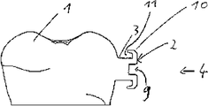
- Fig. 1 is a view of a whole image
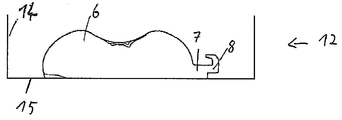
- Fig. 2 is a view of a model
- Fig. 3 is a view of a mold
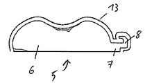
- Fig. 4 is a view of a model with tray
- Fig. 5 is a view of a single-row shape
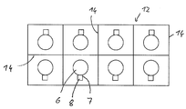
- Fig. 6 is a view of a double row shape
- FIG. 1 shows an entire image, including a dental crown image 1, a connection image 3 and a bracket image 2.
- the bracket image 2 has a wire leadthrough 9 and two wings 10 and wing-shaped rear sections 11.
- FIG. 2 shows a model 5 comprising a tooth crown part 6, a connecting part 7 and a bracket part 8. It can be seen that the bracket part 8 has a blade rear section 11. Also of the wire feedthrough 9 or its undercut part in the bracket part 8 is included. As a result, the bracket part 8 has two undercuts. Also, the tooth crown part 6 has in this embodiment on the left side to recognize a small undercut.
- a tray can be created in different ways.
- FIG. 3 shows a mold 12 for producing a tray by pouring.
- the mold 12 includes, in addition to the model 5 already shown in FIG. 2, which includes a crown part 6 and a connecting part 7 and a bracket part 8, a bottom 15 and walls 14.
- the walls 14 provide a closed mold 12 which can be poured with appropriate material. This allows the tray to be created.
- FIG. 4 shows a production of a tray 13 using a thermoforming sheet.
- model 5 including a crown part 6, a connecting part 7 and a bracket part 8.
- At this Tray 13 is made by deep drawing a thermoforming sheet.
- FIG. 5 shows a mold 12, comprising a plurality of tooth crown parts 6, connecting parts 7 and bracketing parts 8.
- the mold 12 is enclosed by walls 14. Also shown are broken lines, in the place of which the tray resulting from casting can be divided so that individual trays are formed ,
- FIG. 6 shows a double-row mold 12, comprising eight tooth crown parts 6, connecting parts 7 and Brackette parts 8.
- the mold 12 not only has outer walls 14. Rather, it also has internal walls 14 which extend horizontally and vertically and subdivide the mold 12 into eight individual shapes, with the aid of which, in a simple operation, eight individual trays can be generated directly.
Abstract
Description
nur jeweils mindestens eines Bracketteils der mindestens zwei Bracketabbilder beziehungsweise Brackets umfassen. Dabei erstreckt sich jeweils der mindestens eine Bracketteil von der Kauffläche der zugeordneten Zahnkrone aus gesehen vertikal bis maximal zum Ende der Drahtführung und/oder bis zum Ende des ersten Hinterschnitts des Brackets und/oder Bracketabbildes, der bei der Betrachtung von der Kaufläche aus nach dem oberen Flügels angeordnet ist.The trays are characterized in that they each impression only at least one tooth crown part of the at least two tooth crowns and
only in each case comprise at least one bracket part of the at least two bracket images or brackets. In this case, each of the at least one bracket part extends from the purchase surface of the associated tooth crown vertically up to the end of the wire guide and / or to the end of the first undercut of the bracket and / or bracket image, the viewed from the occlusal surface of the upper Wing is arranged.
- Zahnkronenabbild
- Bracketabbild
- Verbindungsabbild
- Ganzes Abbild
- Modell
- Zahnkronenteil
- Verbindungsteil
- Backetteil
- Drahtdurchführung
- Oberer Flügel
- Flügelhinterschnitt
- Form
- Tray
- Wand
- Boden
- Schnittlinie
- Crown image
- bracket image
- connection image
- Whole image
- model
- Crown part
- connecting part
- Backetteil
- Grommet
- Upper wing
- Wing undercut
- shape
- tray
- wall
- ground
- intersection
Claims (15)
- Verfahren zur Herstellung von individuellen Trays (13) zum Positionieren von Brackets, umfassend die Schritte:A method of making individual trays (13) for positioning brackets comprising the steps of:a) Herstellen eines realen Modells (5), wobei das mindestens eine Modell Abbild von zumindest Abschnitten von mindestens zwei Zahnkronen von in einem Kiefer befindlichen Zähnen ist und den Abbildern der Zahnkornen zugeordnete Bracketabbilder oder Brackets beinhaltet;a) producing a real model (5), wherein the at least one model is an image of at least portions of at least two dental crowns of teeth located in a jaw and includes images of brackets associated with the images of the dental cores;b) Herstellen von zumindest zwei Trays (13) durch Herstellen mindestens einer Abformung des realen Modells (5), die jeweils geeignet sind, mindestens eine der mindestens zwei Zahnkronen und ein zu dem der jeweiligen Zahnkrone zugeordneten Bracket oder zu dem zugeordnetem Bracketabbild korrespondierendes reales Bracket zumindest teilweise so aufzunehmen, dass die Anordnung des Bracketabbilds oder Brackets (2) und der Abbildung der Zahnkrone (1) im Modell durch das aufgenommene Bracket und die aufgenommene Zahnkrone real wiedergegeben wird,b) producing at least two trays (13) by producing at least one impression of the real model (5), which are respectively suitable, at least one of the at least two tooth crowns and a bracket associated with the respective tooth crown or corresponding to the associated bracket image real bracket at least partially so that the arrangement of the bracket image or bracket (2) and the image of the tooth crown (1) in the model by the recorded bracket and the recorded tooth crown is actually reproduced,dadurch gekennzeichnet, characterized,dass die Trays (13) jeweils Abformung nur jeweils mindestens eines Zahnkronenteils (6) der mindestens zwei Zahnkronen und that the trays (13) each impression only in each case at least one tooth crown part (6) of the at least two tooth crowns andnur jeweils mindestens eines Bracketteils (8) der mindestens zwei Bracketabbilder beziehungsweise Brackets umfassen, only in each case at least one bracket part (8) of the at least two bracket images or brackets,wobei sich jeweils der mindestens eine Bracketteil (8) von der Kauffläche der zugeordneten Zahnkrone aus gesehen vertikal bis maximal zum Ende der Drahtführung (9) und/oder bis zum Ende des ersten Hinterschnitts des Brackets und/oder Bracketabbildes, der bei der Betrachtung von der Kaufläche aus nach dem oberen Flügels (10) angeordnet ist, erstreckt.wherein in each case the at least one bracket part (8) seen from the purchase surface of the associated tooth crown vertically up to the end of the wire guide (9) and / or to the end of the first undercut of the bracket and / or bracket image, which in the consideration of the Chewing surface from the upper wing (10) is arranged extends.
- Verfahren nach Anspruch 1, wobei sich jeweils der mindestens eine Bracketteil (8) von der Kauffläche der zugeordneten Zahnkrone aus gesehen vertikal bis maximal, insbesondere bis, zu dem Beginn der Drahtführung (9) und/oder bis maximal, insbesondere bis, zu dem Beginn des ersten Hinterschnitts des Brackets und/oder Bracketabbildes, der unterhalb des oberen Flügels (10) angeordnet ist, erstreckt.The method of claim 1, wherein in each case the at least one bracket part (8) seen from the purchase surface of the associated tooth crown from vertical to maximum, in particular until, at the beginning of the wire guide (9) and / or to a maximum, in particular, to the beginning the first undercut of the bracket and / or bracket image, which is arranged below the upper wing (10) extends.
- Verfahren nach einem der vorstehenden Ansprüche, wobei sich insbesondere der mindestens eine Zahnkronenteil (6) von der Kauffläche aus vertikal bis maximal, insbesondere bis, zum ersten Hinterschnitt der entsprechenden Zahnkrone erstreckt.Method according to one of the preceding claims, wherein in particular the at least one tooth crown part (6) extends from the purchase surface vertically to a maximum, in particular to, the first undercut of the corresponding tooth crown.
- Verfahren nach einem der vorstehenden Ansprüche, wobei das reale Modell (5) von den Brackets nur die Bracketteile (8) und/oder von den Zahnkronen nur die Zahnkronenteile (6) beinhaltet.Method according to one of the preceding claims, wherein the real model (5) of the brackets includes only the Brackette parts (8) and / or of the dental crowns only the tooth crown parts (6).
- Verfahren nach einem der vorstehenden Ansprüche 1 bis 4, wobei das reale Modell (5) mehr Abbild der mindestens einen Zahnkrone als der Zahnkronenteil (6) und/oder mehr Abbild des Bracketabbildes beziehungsweise Brackets als der Bracketteil (8) umfasst und die mindestens zwei Trays(13) nach er Abformung zunächst ebenfalls mehr Abformung aufweisen und nach der Abformung entsprechend gekürzt werden, insbesondere durch Schleifen.Method according to one of the preceding claims 1 to 4, wherein the real model (5) comprises more image of the at least one tooth crown than the tooth crown part (6) and / or more image of the bracket image or bracket than the bracket part (8) and the at least two trays (13) after taking the impression initially also have more impression and be shortened accordingly after the impression, in particular by grinding.
- Verfahren nach einem der vorstehenden Ansprüche, wobei in Schritt b) zunächst eine Abformung erstellt und diese anschließend so zerteilt wird, dass jedes Teilstück Abbild von nur einer Zahnkrone mit Bracket ist.Method according to one of the preceding claims, wherein in step b) first an impression is made and this is then divided so that each portion image of only one tooth crown with bracket.
- Verfahren nach einem der Ansprüche 1 bis 4, wobei in Schritt b) zunächst mindestens zwei Teilabformungen erstellt werden, so dass jede Teilabformung Abbild von nur einer Zahnkrone mit Bracket ist.Method according to one of claims 1 to 4, wherein in step b) first at least two partial impressions are created, so that each partial impression image of only one tooth crown with bracket.
- Verfahren nach einem der vorstehenden Ansprüche, wobei im realen Modell (5) die Abbilder der Zahnkronen entlang von parallel verlaufenden Geraden, insbesondere entlang einer oder zwei parallel verlaufenden Geraden, angeordnet sind.Method according to one of the preceding claims, wherein in the real model (5) the images of the dental crowns are arranged along parallel straight lines, in particular along one or two parallel straight lines.
- Verfahren nach einem der vorstehenden Ansprüche, wobei das Modell (5) neben den Abbildern weitere Vorrichtungen (14, 15) zum Abformen, insbesondere Tiefziehen und/oder Abgießen beinhaltet.Method according to one of the preceding claims, wherein the model (5) in addition to the images further devices (14, 15) for molding, in particular deep drawing and / or casting includes.
- Verfahren nach einem der vorstehenden Ansprüche, wobei die mindestens eine Abformung durch Abgießen des Modells (3) erstellt wird und insbesondere als Abgießmasse eine solche verwendet wird, die beim Härten schrumpft.Method according to one of the preceding claims, wherein the at least one impression is made by casting the model (3) and in particular as Abgießmasse one is used, which shrinks during curing.
- Verfahren nach einem der Ansprüche 1 bis 9, wobei die mindestens eine Abformung durch Tiefziehen einer Tiefziehfolie am Modell erstellt wird.Method according to one of claims 1 to 9, wherein the at least one impression is made by deep-drawing a thermoforming sheet on the model.
- Verfahren nach einem der vorstehenden Ansprüche, wobei nach Schritt b) mindestens ein Bracket so in das Tray eingesetzt wird, dass es dort so angeordnet ist, wie die Bracketabbilder beziehungsweise Brackets bei der Herstellung des mindestens einen Trays angeordnet waren und insbesondere durch eine Klemmwirkung gehalten werden.Method according to one of the preceding claims, wherein after step b) at least one bracket is inserted into the tray so that it is arranged there, as the bracket images or brackets were arranged in the production of the at least one tray and are held in particular by a clamping action ,
- Verfahren nach Anspruch 12, wobei die Brackets in Hinterschnitte des Trays eingedreht werden.The method of claim 12, wherein the brackets are screwed into undercuts of the tray.
- Verfahren nach einem der vorstehenden Ansprüche, bei dem auf jedem Tray (13) eine Griffhilfe angebracht wird.Method according to one of the preceding claims, in which a handle aid is attached to each tray (13).
- Tray zur Platzierung mindestens eines Brackets auf einer Zahnkrone, dadurch gekennzeichnet, dass das Tray (13) lediglich einen Bracketteil (8) jedes Bracketabbildes beziehungsweise Brackets umfasst, der sich von der Kauffläche aus gesehen vertikal bis maximal zum Ende der Drahtführung (9) und/oder zum Ende des ersten Hinterschnitt des Brackets und/oder Bracketabbildes, der unterhalb des oberen Flügels (10) angeordnet ist, erstreckt.Tray for placing at least one bracket on a dental crown, characterized in that the tray (13) comprises only one bracket part (8) of each bracket image or bracket, viewed from the purchase surface vertically to a maximum of the end of the wire guide (9) and / or to the end of the first undercut of the bracket and / or bracket image, which is arranged below the upper wing (10) extends.
Priority Applications (8)
| Application Number | Priority Date | Filing Date | Title |
|---|---|---|---|
| JP2014503160A JP2014514064A (en) | 2011-04-05 | 2012-04-05 | Manufacturing method of bracket tray |
| RU2013146179/14A RU2013146179A (en) | 2011-04-05 | 2012-04-05 | METHOD FOR PRODUCING PRINTING SPOONS FOR BRACKETS |
| EP12720813.0A EP2693974B1 (en) | 2011-04-05 | 2012-04-05 | Method for producing trays for brackets |
| US14/009,739 US10390907B2 (en) | 2011-04-05 | 2012-04-05 | Method for producing trays for brackets |
| KR1020137029165A KR20140024363A (en) | 2011-04-05 | 2012-04-05 | Method for producing trays for brackets |
| BR112013025546A BR112013025546A2 (en) | 2011-04-05 | 2012-04-05 | Method for producing individual trays for positioning orthodontic brackets and tray for positioning at least one orthodontic bracket on a tooth crown |
| CN201280026173.XA CN103561677A (en) | 2011-04-05 | 2012-04-05 | Method for producing trays for brackets |
| CA2832140A CA2832140A1 (en) | 2011-04-05 | 2012-04-05 | Method for producing trays for brackets |
Applications Claiming Priority (2)
| Application Number | Priority Date | Filing Date | Title |
|---|---|---|---|
| EPPCT/EP2011/055258 | 2011-04-05 | ||
| PCT/EP2011/055258 WO2012136247A1 (en) | 2011-04-05 | 2011-04-05 | Method for producing trays for brackets |
Publications (1)
| Publication Number | Publication Date |
|---|---|
| WO2012136803A1 true WO2012136803A1 (en) | 2012-10-11 |
Family
ID=46085001
Family Applications (2)
| Application Number | Title | Priority Date | Filing Date |
|---|---|---|---|
| PCT/EP2011/055258 WO2012136247A1 (en) | 2011-04-05 | 2011-04-05 | Method for producing trays for brackets |
| PCT/EP2012/056349 WO2012136803A1 (en) | 2011-04-05 | 2012-04-05 | Method for producing trays for brackets |
Family Applications Before (1)
| Application Number | Title | Priority Date | Filing Date |
|---|---|---|---|
| PCT/EP2011/055258 WO2012136247A1 (en) | 2011-04-05 | 2011-04-05 | Method for producing trays for brackets |
Country Status (9)
| Country | Link |
|---|---|
| US (1) | US10390907B2 (en) |
| EP (1) | EP2693974B1 (en) |
| JP (1) | JP2014514064A (en) |
| KR (1) | KR20140024363A (en) |
| CN (1) | CN103561677A (en) |
| BR (1) | BR112013025546A2 (en) |
| CA (1) | CA2832140A1 (en) |
| RU (1) | RU2013146179A (en) |
| WO (2) | WO2012136247A1 (en) |
Families Citing this family (7)
| Publication number | Priority date | Publication date | Assignee | Title |
|---|---|---|---|---|
| JP6478918B2 (en) * | 2012-12-11 | 2019-03-06 | スリーエム イノベイティブ プロパティズ カンパニー | Mockup representing a dental arch containing an analogue similar to an orthodontic bracket and method of making the mockup |
| EP2886077A1 (en) * | 2013-12-18 | 2015-06-24 | 3M Innovative Properties Company | Method of making a transfer tray |
| US11432911B2 (en) * | 2014-10-14 | 2022-09-06 | Paul Ouellette | Integrated braces with veneers, crowns, or bridges |
| DE102016108630A1 (en) * | 2016-05-10 | 2017-11-16 | Yong-min Jo | Device for correcting misaligned teeth and method for its production |
| US10881487B2 (en) * | 2016-06-30 | 2021-01-05 | Align Technology, Inc. | Insertable and prefabricated attachments for an oral appliance |
| AU2019343305A1 (en) * | 2018-09-20 | 2021-04-08 | Torsten HERTING | Method for positioning a workpiece and apparatus therefor |
| DE102022110539A1 (en) * | 2022-04-29 | 2023-11-02 | Ca-Digital Gmbh | Method for producing a fastening aid for fastening a retainer to a patient's teeth |
Citations (7)
| Publication number | Priority date | Publication date | Assignee | Title |
|---|---|---|---|---|
| US3738005A (en) | 1972-03-22 | 1973-06-12 | M Cohen | Method and apparatus for applying orthodontic brackets and the like |
| US20070031775A1 (en) * | 2002-05-28 | 2007-02-08 | Ormco Corporation | Custom orthodontic bracket placement jig and jig making method and apparatus |
| WO2007129833A1 (en) * | 2006-05-04 | 2007-11-15 | Orapix Co., Ltd. | Bracket for revising a set of teeth, bracket positioning jig, system for revising a set of teeth using the same, and method of making the jig |
| EP1941842A2 (en) | 2002-02-13 | 2008-07-09 | T.O.P. Service für Lingualtechnik GmbH | Modular system for customized orthodontic appliances |
| US20080227050A1 (en) * | 2006-08-17 | 2008-09-18 | Marshall Michael C | Bracket alignment devices and systems and methods of producing and utilizing the same |
| WO2009020282A1 (en) * | 2007-08-09 | 2009-02-12 | Joonho Lee | Transfer jig for bracket or tube, manufacturing and using method thereof |
| FR2959929A1 (en) * | 2010-05-17 | 2011-11-18 | H 32 | INDIVIDUALIZED TEMPLATE FOR ORTHODONTIC APPARATUS, ASSEMBLY FORMED BY THIS TEMPLATE, BASE AND ATTACHMENT, AND DESIGN METHODS THEREOF. |
Family Cites Families (19)
| Publication number | Priority date | Publication date | Assignee | Title |
|---|---|---|---|---|
| US4360341A (en) * | 1981-03-16 | 1982-11-23 | Dellinger Eugene L | Orthodontic method for treating malocclusion |
| US4657508A (en) * | 1983-12-19 | 1987-04-14 | Dellinger Eugene L | Orthodontic apparatus and method for treating malocclusion |
| US4626208A (en) * | 1985-08-16 | 1986-12-02 | Tp Orthodontics, Inc. | Positioning jig for edgewise bracket |
| NL9002792A (en) * | 1990-12-18 | 1992-07-16 | Orthodontie Research Bv | METHOD FOR APPLYING A DENTAL DEVICE AND USING A MOLD THEREOF |
| US5863198A (en) * | 1996-09-23 | 1999-01-26 | Doyle; Walter A. | Orthodontic bracket placement jig |
| US5938435A (en) * | 1997-07-22 | 1999-08-17 | Raspino, Jr.; Jude G. | Orthodontic appliance shield system |
| US5971754A (en) * | 1998-07-30 | 1999-10-26 | Sondhi; Anoop | Indirect bonding method and adhesive for orthodontic treatment |
| US6123544A (en) * | 1998-12-18 | 2000-09-26 | 3M Innovative Properties Company | Method and apparatus for precise bond placement of orthodontic appliances |
| US8251699B2 (en) * | 2002-12-31 | 2012-08-28 | Brian C. Reising | Orthodontic bracket and method of attaching orthodontic brackets to teeth |
| US20040166462A1 (en) * | 2003-02-26 | 2004-08-26 | Align Technology, Inc. | Systems and methods for fabricating a dental template |
| US7137812B2 (en) * | 2003-10-03 | 2006-11-21 | 3M Innovative Properties Company | Apparatus for indirect bonding of orthodontic appliances and method of making the same |
| DK3449865T3 (en) * | 2004-03-04 | 2020-06-02 | Align Technology Inc | Computer-implemented method of providing a digital representation of an orthodontic template for positioning an object on a patient's tooth |
| US7168950B2 (en) * | 2004-10-18 | 2007-01-30 | 3M Innovative Properties Company | Orthodontic methods and apparatus for applying a composition to a patient's teeth |
| US8308478B2 (en) * | 2005-03-01 | 2012-11-13 | Dentsply International Inc. | Methods for indirect bonding of orthodontic appliances |
| US7762815B2 (en) * | 2005-05-13 | 2010-07-27 | 3M Innovative Properties Co. | Method of making an indirect bonding tray for orthodontic treatment |
| KR100865079B1 (en) * | 2006-05-04 | 2008-10-24 | 주식회사 오라픽스 | Bracket Positioning Jig for A Set of Teeth and Method of Making the Same |
| US7473096B2 (en) * | 2006-06-21 | 2009-01-06 | 3M Innovative Properties Company | Orthodontic adhesive dispensing assembly |
| JP2011505195A (en) * | 2007-11-29 | 2011-02-24 | スリーエム イノベイティブ プロパティズ カンパニー | Method and apparatus for applying a dental sealant to the teeth of an orthodontic patient |
| US8235715B2 (en) * | 2008-12-18 | 2012-08-07 | Align Technology, Inc. | UV and chemical cure blocking dental template |
-
2011
- 2011-04-05 WO PCT/EP2011/055258 patent/WO2012136247A1/en active Application Filing
-
2012
- 2012-04-05 RU RU2013146179/14A patent/RU2013146179A/en not_active Application Discontinuation
- 2012-04-05 JP JP2014503160A patent/JP2014514064A/en active Pending
- 2012-04-05 EP EP12720813.0A patent/EP2693974B1/en active Active
- 2012-04-05 US US14/009,739 patent/US10390907B2/en active Active
- 2012-04-05 BR BR112013025546A patent/BR112013025546A2/en not_active IP Right Cessation
- 2012-04-05 WO PCT/EP2012/056349 patent/WO2012136803A1/en active Application Filing
- 2012-04-05 KR KR1020137029165A patent/KR20140024363A/en not_active Application Discontinuation
- 2012-04-05 CN CN201280026173.XA patent/CN103561677A/en active Pending
- 2012-04-05 CA CA2832140A patent/CA2832140A1/en not_active Abandoned
Patent Citations (7)
| Publication number | Priority date | Publication date | Assignee | Title |
|---|---|---|---|---|
| US3738005A (en) | 1972-03-22 | 1973-06-12 | M Cohen | Method and apparatus for applying orthodontic brackets and the like |
| EP1941842A2 (en) | 2002-02-13 | 2008-07-09 | T.O.P. Service für Lingualtechnik GmbH | Modular system for customized orthodontic appliances |
| US20070031775A1 (en) * | 2002-05-28 | 2007-02-08 | Ormco Corporation | Custom orthodontic bracket placement jig and jig making method and apparatus |
| WO2007129833A1 (en) * | 2006-05-04 | 2007-11-15 | Orapix Co., Ltd. | Bracket for revising a set of teeth, bracket positioning jig, system for revising a set of teeth using the same, and method of making the jig |
| US20080227050A1 (en) * | 2006-08-17 | 2008-09-18 | Marshall Michael C | Bracket alignment devices and systems and methods of producing and utilizing the same |
| WO2009020282A1 (en) * | 2007-08-09 | 2009-02-12 | Joonho Lee | Transfer jig for bracket or tube, manufacturing and using method thereof |
| FR2959929A1 (en) * | 2010-05-17 | 2011-11-18 | H 32 | INDIVIDUALIZED TEMPLATE FOR ORTHODONTIC APPARATUS, ASSEMBLY FORMED BY THIS TEMPLATE, BASE AND ATTACHMENT, AND DESIGN METHODS THEREOF. |
Also Published As
| Publication number | Publication date |
|---|---|
| EP2693974B1 (en) | 2019-10-23 |
| WO2012136247A1 (en) | 2012-10-11 |
| US20140178828A1 (en) | 2014-06-26 |
| RU2013146179A (en) | 2015-05-10 |
| BR112013025546A2 (en) | 2016-12-27 |
| JP2014514064A (en) | 2014-06-19 |
| US10390907B2 (en) | 2019-08-27 |
| EP2693974A1 (en) | 2014-02-12 |
| CN103561677A (en) | 2014-02-05 |
| CA2832140A1 (en) | 2012-10-11 |
| KR20140024363A (en) | 2014-02-28 |
Similar Documents
| Publication | Publication Date | Title |
|---|---|---|
| EP2693974B1 (en) | Method for producing trays for brackets | |
| EP3229724B1 (en) | Method for producing a dental prosthesis using a template | |
| EP3188685B1 (en) | Method for producing a positioning tray and the device therefor | |
| EP3348227B1 (en) | Method for producing a three-dimensional model of a section of a jaw | |
| DE102007036549A1 (en) | Placement jig for locating orthodontic appliance on tooth of patient, has jig locating areas shaped to conform to specific areas on teeth to hold orthodontic appliance of preset configuration and orientation | |
| EP3128944B1 (en) | Method for processing prefabricated prosthetic teeth | |
| EP3256068B1 (en) | Creation of a wax base or plastic base for a dental prosthesis | |
| DE102017108592B4 (en) | Method for producing a dental prosthesis with parallel roots of the denture teeth | |
| DE102017113814B4 (en) | Process for the production of a dental prosthesis with a defined adhesive gap | |
| EP3223743B1 (en) | Bite registration tool, bite registration tool set, and suitable bite registration method | |
| DE102011003892A1 (en) | Method for producing at least one patient-specific, modularly constructed bracket and associated bracket | |
| EP2672921A1 (en) | Method for producing a patient-specific support, and associated support | |
| WO2013188894A1 (en) | Method for positioning artificial posterior teeth | |
| DE102018123318A1 (en) | Pre-product for the production of prosthetic teeth and process for its production and processing | |
| WO2014060577A1 (en) | Segmented dental model | |
| DE102009043048B4 (en) | Bite holder, arrangement of single-tooth models and denture holder and method for simplified transfer of a virtual tooth position in a real denture model | |
| WO2014118056A1 (en) | Method for producing removable dental appliances | |
| DE102019105956A1 (en) | Process for the production of an individual impression tray | |
| DE102021112178B4 (en) | Method and device for manufacturing a dental prosthesis | |
| DE3904699C1 (en) | Dental impression tray | |
| DE102020126122A1 (en) | Method of making an orthodontic appliance | |
| DE3843757A1 (en) | METHOD FOR PRODUCING A DENTAL PROSTHESIS | |
| WO2014075810A1 (en) | Dental impression device, dental impression set and method for moulding and correctly positioned registration of a jaw arrangement | |
| EP3513764A1 (en) | Arrangement for the production of multiple differently shaped dental splints | |
| DE102011103587A1 (en) | Apparatus and method for three-dimensional midface related repositioning or repositioning of a jaw component |
Legal Events
| Date | Code | Title | Description |
|---|---|---|---|
| 121 | Ep: the epo has been informed by wipo that ep was designated in this application |
Ref document number: 12720813 Country of ref document: EP Kind code of ref document: A1 |
|
| ENP | Entry into the national phase |
Ref document number: 2832140 Country of ref document: CA |
|
| ENP | Entry into the national phase |
Ref document number: 2014503160 Country of ref document: JP Kind code of ref document: A |
|
| NENP | Non-entry into the national phase |
Ref country code: DE |
|
| ENP | Entry into the national phase |
Ref document number: 20137029165 Country of ref document: KR Kind code of ref document: A |
|
| WWE | Wipo information: entry into national phase |
Ref document number: 2012720813 Country of ref document: EP |
|
| ENP | Entry into the national phase |
Ref document number: 2013146179 Country of ref document: RU Kind code of ref document: A |
|
| WWE | Wipo information: entry into national phase |
Ref document number: 14009739 Country of ref document: US |
|
| REG | Reference to national code |
Ref country code: BR Ref legal event code: B01A Ref document number: 112013025546 Country of ref document: BR |
|
| ENP | Entry into the national phase |
Ref document number: 112013025546 Country of ref document: BR Kind code of ref document: A2 Effective date: 20131003 |