WO1999059106A1 - Method and apparatus for generating 3d models from medical images - Google Patents
Method and apparatus for generating 3d models from medical images Download PDFInfo
- Publication number
- WO1999059106A1 WO1999059106A1 PCT/US1999/010566 US9910566W WO9959106A1 WO 1999059106 A1 WO1999059106 A1 WO 1999059106A1 US 9910566 W US9910566 W US 9910566W WO 9959106 A1 WO9959106 A1 WO 9959106A1
- Authority
- WO
- WIPO (PCT)
- Prior art keywords
- patient
- images
- tooth
- model
- points
- Prior art date
Links
Classifications
-
- A—HUMAN NECESSITIES
- A61—MEDICAL OR VETERINARY SCIENCE; HYGIENE
- A61C—DENTISTRY; APPARATUS OR METHODS FOR ORAL OR DENTAL HYGIENE
- A61C9/00—Impression cups, i.e. impression trays; Impression methods
- A61C9/004—Means or methods for taking digitized impressions
- A61C9/0046—Data acquisition means or methods
-
- G—PHYSICS
- G06—COMPUTING; CALCULATING OR COUNTING
- G06T—IMAGE DATA PROCESSING OR GENERATION, IN GENERAL
- G06T7/00—Image analysis
- G06T7/80—Analysis of captured images to determine intrinsic or extrinsic camera parameters, i.e. camera calibration
-
- G—PHYSICS
- G06—COMPUTING; CALCULATING OR COUNTING
- G06V—IMAGE OR VIDEO RECOGNITION OR UNDERSTANDING
- G06V10/00—Arrangements for image or video recognition or understanding
- G06V10/10—Image acquisition
- G06V10/12—Details of acquisition arrangements; Constructional details thereof
- G06V10/14—Optical characteristics of the device performing the acquisition or on the illumination arrangements
- G06V10/147—Details of sensors, e.g. sensor lenses
-
- A—HUMAN NECESSITIES
- A61—MEDICAL OR VETERINARY SCIENCE; HYGIENE
- A61B—DIAGNOSIS; SURGERY; IDENTIFICATION
- A61B34/00—Computer-aided surgery; Manipulators or robots specially adapted for use in surgery
- A61B34/10—Computer-aided planning, simulation or modelling of surgical operations
-
- A—HUMAN NECESSITIES
- A61—MEDICAL OR VETERINARY SCIENCE; HYGIENE
- A61B—DIAGNOSIS; SURGERY; IDENTIFICATION
- A61B90/00—Instruments, implements or accessories specially adapted for surgery or diagnosis and not covered by any of the groups A61B1/00 - A61B50/00, e.g. for luxation treatment or for protecting wound edges
- A61B90/36—Image-producing devices or illumination devices not otherwise provided for
-
- G—PHYSICS
- G06—COMPUTING; CALCULATING OR COUNTING
- G06T—IMAGE DATA PROCESSING OR GENERATION, IN GENERAL
- G06T2207/00—Indexing scheme for image analysis or image enhancement
- G06T2207/30—Subject of image; Context of image processing
- G06T2207/30004—Biomedical image processing
Definitions
- the Field of the Invention relates to the field of medical imaging.
- the invention relates to the generation and use of three-dimensional medical images
- model builders will frequently manually remove unneeded vertices to simplify the processing required when displaying and manipulating a three-
- Such three-dimensional models are typically rendered as wire frames. That is, a plurality of points are identified, corresponding to the points at which image information is captured and the points are displayed together with lines
- wireframes because the lines between the points appear to constitute a wire mesh.
- the individual points in such a wireframe are
- VRML Virtual Reality Mark-up Language
- Wireframe models are commercially available from a variety of sources.
- magnetic resonance imaging (MRI) and other imaging technologies, can accurately display two-dimensional slices of a patient.
- an irregular shape in a 3-D model of a skull may be a tumor, but the system does not relate this additional information to the
- the 3-D model does not even have information indicating
- imaging technologies e.g., x-rays, MRIs and
- Inc. are commonly used to generate and manipulate three-dimensional models.
- the user interfaces of available commercial software for dealing with three- dimensional models are highly technical and generally unsuited for use by a
- the 3-D models do not are not related to medical information about a patient (e.g., a shape in a 3-D
- model is only a shape, there is no information that the shape is a tumor or body part). Also, some technologies do not allow doctors to build models from
- One aspect of the invention is directed to providing a generic software tool
- a number of modules are used to achieve this result.
- These modules include a Sculptor module, a Clinician module and an Executor
- the Sculptor module maps all acquired imaging, including those from
- the Sculptor allows a user to identify the location of different anatomical points in each of the
- the Sculptor allows a user to relate different anatomical points to each other in a 3-D space and also relate the points to the images.
- the Clinician/Consultant module uses the related points to modify or
- a stock model e.g., a standard anatomical 3-D model.
- the customized model that is created corresponds to a 3-D model of the patient's anatomy.
- the model is "smart" in that when certain changes are made to the dot
- the remainder of the model can be adjusted or
- an object representing the patient's tooth is associated with data indicating that the object
- the Clinician/Consultant is a database query tool that allows for display or visualization of the anatomy and function, manipulation of objects for treatment planning and model analyses.
- a third module is a database that provides overall system file and image management and coordinates the Sculptor module and the
- the stock model is a model of
- this model has approximately 300 objects which can be
- Some embodiments of the invention include the functionality of some or all of the above modules. For example, in some embodiments, only a subset of the above modules.
- Sculptor functions performed by the Sculptor are included (e.g., the ability to define related points in multiple images).
- Figure 1 illustrates a computer system including one embodiment of the
- FIG. 2 illustrates an architecture of the software used in one embodiment
- Figure 3 illustrates capturing images for use in the system.
- Figure 4 and Figure 5 illustrates the calibration frame.
- Figure 6 illustrates an example method calibrating images, generating a patient specific model, and performing analysis from the calibrated images and the patient specific model.
- Figure 7 through Figure 24 illustrates user interfaces for a sculpture
- Figure 25 through Figure 40 illustrates user interfaces for a clinician
- Computer - is any computing device (e.g., PC compatible computer, Unix
- a computer includes a processor
- a computer can include a network of computers.
- Handheld Device or Palmtop Computer
- Examples of a handheld device include the Palm IIITM handheld computer and Microsoft's palm sized
- Internet - is a collection of information stored in computers physically located throughout the world. Much of the information on the Internet is organized onto electronic pages. Users typically bring one page to their
- Client - a computer used by the user to make a query.
- Server - a computer that supplies information in response to a query, or performs intermediary tasks between a client and another server.
- World Wide Web (or Web or web) - is one aspect of the Internet that
- Program - a sequence of instructions that can be executed by a computer.
- program can include other programs.
- a program can include only one
- Application - is a program.
- the operations are machine operations.
- Useful machines for performing the operation of the present invention include
- the present invention also relates to apparatus for performing these
- This apparatus may be specially constructed for the required
- Figure 1 illustrates a computer 110 that can be used to carry out the
- Figure 1 includes a computer 110, a sculptor 115, a clinician/consultant 125, and an executor 135.
- the sculptor 115 includes a display of a user interface having a number of patient images 150 that also show a calibration frame 140.
- the clinician/consultant 125 includes a similar user interface that includes a a view of a patient specific model 160 and an analysis window 127.
- window 127 includes an example analysis 170.
- the executor 135 includes image
- the sculptor 115 and the clinician/consultant 125 can extract and manipulate information from the image data 137 and the patient model data 139 through the executor 135. The following paragraphs describe the elements of Figure 1 in greater detail.
- the computer 110 represents a computer system upon which the sculptor 115, the clinician/consultant 125, and the executor 135 can execute.
- the computer 110 is representative of a standard personal computer such as is
- computers could be used as the computer 110. What is important is that the computer 110 some sort of processor and some memory.
- the sculptor 115 and the executor 135 may run on one computer at one time. While at another time, the
- clinician/consultant 125 and the executor 135 can run on another computer at another time. Alternatively, all three programs can run on different computers.
- the computers can be linked together by a network such as the Internet.
- the sculptor 115 represents a computer program in which a number of different types of patient images 150 can be calibrated using the images of the
- the sculptor 115 allows a technician to calibrate the images and identify
- the patient images 150 can be extracted from the image data 137.
- image data 137 can be imported from an external source either by transmission
- the image data 137 need not be retrieved from the executor 135.
- the image data may be directly imported into the sculptor 115
- the calibration frame 140 is an apparatus that includes a number of
- the calibration frame 140 is worn by the patient during the capturing of the patient images.
- the patient model data 139 represents the data generated by the sculptor 115
- This output of the sculptor 115 can be included the form of two transport files, the (.sci file and .cln
- the stock anatomy model is 3D model of a standard
- the clinician/consultant 125 morphs the stock model into the patient specific model, allows users
- the clinician/consultant 125 can be used to perform various types of analyses on
- results of these analyses can be then displayed on the patient images and as well as in the example analysis window 127.
- the particular model used will be a stock model of a human skull.
- the human skull can be used by an
- the model will have a number of objects including objects corresponding to each of the patient's teeth, the jaw, and other elements
- each of these objects can be manipulated individually in the clinician/consultant 125.
- An example of a stock model that may be used is one from Viewpoint Data Labs which is specifically created for orthodontic applications. A full custom
- stock model can also be used.
- the stock model represents the average structure of a piece of anatomy.
- the Executor will compile normative stock models to match patient demographics of age, race, sex and body type.
- stock model has a coordinate system where each point is referenced to another
- Figure 2 illustrates the various responsibilities of each of the three programs of Figure 1.
- the sculptor 115 is responsible for input/output control of the patient images 150.
- the sculptor 115 allows for a calibration between the various
- the sculptor 115 includes a graphical user interface for performing the various features of the sculptor 115.
- the viewer supports the viewing of 3D models (useful where a piece of anatomy needs a more detailed
- model matching allows a user to match portions of the stock model to points on one or more patient images 150.
- model matching includes
- the sculptor 115 can be defined. These new locations can then be used for more
- the sculptor 115 allows the user to identify the location of previously undefined points of the stock model in the patient images 150.
- the executor 135 takes responsibility for the database storage and
- the executor 135 includes Internet access for communicating with one or more
- the executor 135 also has encryption capabilities to protect the security of the information stored by
- the clinician/consultant 125 includes the following functions. Diagnosis,
- treatment planning, predictions, analyses, and metrics are all examples of the type of functions that can be performed on the patient specific model 160 and
- patient model data 139 Examples of these areas are described in greater detail below.
- the clinician/consultant 125 also keeps track of the stock objects, or
- the clinician/consultant 125 includes a graphical user interface and viewer
- the morph editor is used to modify any morphing that is done to generate
- the simulator simulates the motion of objects within the patient specific
- model 160 The simulator could also be used to simulate the predicted motion of
- the simulator can be used to determine the objects in the patient specific model 160.
- the simulator can be used to determine the objects in the patient specific model 160.
- Figure 3 illustrates example relationships between a patient, a camera and other imaging technologies, for the purpose of capturing images.
- a patient 300, a camera 310 and an x-ray device 320 are shown in Figure 3.
- the camera 310 and the x-ray device 320 can be used to capture the image data
- These captured images can be all from one camera, x-ray machine, or the
- image data about the patient 300 from multiple vantage points Other example modes of image capture include MRIs, ultrasound imaging, infrared imaging, and
- the camera 310 and x-ray 320 are merely symbolic of the fact that
- images of the patient are captured using various types of imaging technology.
- the preferred x-ray images would include a frontal
- preferred photographic images may include a frontal image and two lateral images.
- Figure 4 illustrates a front view and a side view of a calibration frame 140 that may be used in some embodiments of the invention. Images of this calibration frame 140 appears in the patient images 150. The images of the
- calibration frame 140 can then be used in the sculptor 115 to calibrate the
- the calibration process includes recording the anatomy with the calibration
- the sculptor uses knowledge within the sculptor to compute the location of the imaging sources as a point source with seven degrees of freedom (DOF). Seven DOF includes the x, y, z, yaw, pitch,
- the calibration process maps the associated images into the 3D matrix associated with the calibration frame.
- the calibration frame 140 can include a top strap 405, a strap 410, an
- the top strap 405, the strap 410, and the adjustment knob 420, work together to keep the calibration frame
- the top strap 405 is designed to encircle the patient's 300 head.
- the top strap 405 and the strap 410 are part of headgear normally associated with a welding visor from which the face shield has
- a rigid plexi-glass frame 430 is used to mount a number of calibration targets 440.
- the circumference of the strap 410 is adjusted using a ratchet and a knob 420. They can be used to
- the calibration targets 440 provide measurement references during the calibration of the various patient images 150.
- the calibration targets 440 include
- Alternative embodiments can include different materials such as cod liver oil capsules as calibration targets 440. Alternative embodiments can also include different materials such as cod liver oil capsules as calibration targets 440. Alternative embodiments can also include different materials such as cod liver oil capsules as calibration targets 440. Alternative embodiments can also include different materials such as cod liver oil capsules as calibration targets 440. Alternative embodiments can also include different materials such as cod liver oil capsules as calibration targets 440. Alternative embodiments can also include different materials such as cod liver oil capsules as calibration targets 440. Alternative embodiments can also be used.
- calibration targets 440 include different shapes of calibration targets 440, such as crosses.
- BBs such as shot gun pellets
- bearings it is preferred to use bearings
- calibration targets 440 are that they are visible in both optical and x-ray images. However, what is important with respect to the calibration targets 440 is that they provide a fixed reference frame by which patient images 150 can be calibrated. Thus, they should be viewable in each of the patient images 150.
- the calibration targets 440 can be of different types of materials such that some of the calibration targets 440 appear in some of the images while others of the calibration targets appear in others of the images. As long as enough of the calibration targets 440 are visible in enough of the images,
- a single calibration target could be made of different materials.
- a cod liver calibration target could be positioned very close to a crosshair.
- the crosshair would indicate the position of the calibration target in
- the calibration targets 440 are positioned in the calibration frame 140 such that it is unlikely that in any one image the calibration targets will
- calibration targets are visible from each image perspective.
- shape of the calibration frame for holding the calibration targets 440 may vary from
- frame used 140 can also be stored with that information.
- the attachment 450 (also referred to as an appliance) represents another way in which calibration targets can be included in images of the patient 300.
- the calibration attachment 450 can be still used to calibrate. For example, where an x-ray image is collimated to only focus on a smaller portion of the
- FIG. 5 illustrates another embodiment of the calibration frame 140. In this case
- the plexi-glass frame 430 has a number of bends instead of the continuous curve shown in Figure 4. This facilities the attachment of calibration attachments 450 to the calibration frame 140.
- Figure 5 illustrates a top view 502, a front view 504 and a cross section view 506 of the calibration frame 140.
- attachment sites 530 can be included on the calibration frame 140. (Note, the top view 502 does not illustrate the attachment sites 530,
- the cross sectional view 506 illustrates how an attachment can be attached
- attachment 450 can be stabilized using dowel pins 560.
- This example illustrates an acrylic appliance (attachment 450).
- Figure 5 illustrates an acrylic appliance support that can be used
- FIG. 6 illustrates one embodiment of the invention where the programs of
- Figure 1 are executed on one or more computers 110.
- the drawings are executed on one or more computers 110.
- the drawings are executed on one or more computers 110.
- patient images 150 are calibrated to generate the patient specific model 160. This information is also used to perform a number of analyses on the patient
- Figure 6 can be broken down into three general processes: a capturing of the patient specific data 602, generating the patient model 604, and performing analyses and related work on the patient model and
- calibration frame 140 is mounted on the patient 300 head. This can be done by a technician at a medical facility.
- adjustment knob 420 can be use to snuggly fit the calibration frame 140 to the
- a number of different images of the patient are captured.
- the calibration frame 140 and/or the attachments 450 are included in
- the sculptor 115 is used to import all the image data 137.
- This image data 137 is now calibrated using the image information of the calibration frame 140.
- each patient image 150 is associated with a
- calibration frame template (a computer representation of the calibration frame 140). A user will match a calibration frame template up with the image of the calibration frame 140 in each of the patient images 150. This tells the computer 110 how the calibration frame 140 is oriented and positioned in the
- the calibration process involves calibrating locations relative
- a first plane may be defined that is parallel to approximately the patient's pupils.
- a y-plane can then be defined through the
- the last center plane can be determined from the cross product of the other two planes.
- Appendix A includes a list of those locations.
- An example of identifying anatomic location 640 would include such things
- the set of anatomic locations that need to be defined is dependent upon what
- Orthodontists for centuries, may have different specific features of interest that are identified in the identification of anatomic locations. Orthodontists, for centuries
- landmarks in the skull tend to concentrate on landmarks in the skull. These landmarks tend to be points concentrated on the mid-sagittal plane, teeth, and jaw. The ability to identify these landmarks and cross correlate them in the various patient
- images 150 is an important feature for specific medical applications. However, the specific features and anatomic locations that are important to a particular
- the following describes an example way of identifying a landmark in more than one image. It is important to identify the landmark location in multiple
- the user can perform the following steps using the computer 110.
- the user selects a point to be identified.
- the user places that point in one of the images.
- the sculptor 115 then generates a line through that
- the line (epi-polar line) originates from the
- imaging source and is projected through a landmark point of image A and onto
- length of the line can be constrained by a priori knowledge of geographic region
- the point may be automatically defined in all of the other images. Rather than identifying individual points however, it is sometimes desirable
- the tracing can be done by specifying one or more connected points in a number of the patient images 150.
- the patient specific model 160 is generated in the generate patient model 604 process.
- the data for that patient can be exported to the executor 135. This information can then be
- the clinician/consultant 125 includes a stock model which is to be morphed against the information drawn from the sculptor 115 for a particular patient.
- the anatomic locations identified in the sculptor 115 from the patient images 150 are all associated with the calibration frame 140.
- specific model 160 includes all the object information in the original stock model
- the model is shown as a number of dots in space.
- the user can select an analysis type from
- the analysis can be derived from either the landmarks that have been previously identified in the sculptor 115, from the morphed three
- example analysis 170 This conforms to block 670 of Figure 6.
- the example analysis 170 illustrates example output from an analysis procedure.
- measurements may be taken to perform any number of standard orthodontic analyses such as a Ricketts analysis or a McGrann analysis.
- Other types of analysis, treatments, etc. are described in the following sections.
- a user can use the clinician/consultant 125 to rotate
- the patient's face can be mapped
- the user is able to hide objects in the patient specific model 160. This,
- the patient specific model 160 can be rendered by placing a skin over the model to show the external appearance after the
- CAT Computer Assisted Tomography
- the full patient specific information can be transmitted through a relatively low bandwidth network in a relatively small amount of time. Such information could be transported over the Internet to
- measurement data could be taken in the sculptor 115 and sent to a dental lab across the network very quickly and efficiently.
- the patient specific model 160 can be transmitted across the network with the
- calibration targets 440 In this example, BBs will be used as calibration targets, however, the general process can be used for most any type of calibration target.
- the image of each BB is circular in the patient images 150. This is why the
- centroid location in 3D space is then determined as the center of the BB relative to the calibration frame 140. This information can then be stored and
- the user can drag and drop calibration target identifiers near a calibration target, and the computer 110 (the sculptor 115) can look for a calibration target near where the user dropped the calibration target identifier.
- FIG. 7 illustrates the sculptor 115 application interface. This is shown as
- Sculptor interface 715 includes a sculptor toolbar 720 for
- a patient image 750 is being displayed.
- Patient image includes a view of the
- Figure 8 illustrates the placement of an unaligned calibration template 810 in the patient image area.
- the unaligned calibration template 810 will be aligned
- FIG. 9 shows that a number of calibration target selectors 910 have been placed over the calibration targets 440 in the patient image 750.
- the calibration target selector 910 is dragged and dropped onto a calibration target in the image
- Figure 10 illustrates the partially aligned calibration template 110.
- Figure 11 illustrates the aligned calibration template 1110.
- calibration template 1110 now provides the sculptor 1115 with a reference frame for the patient image 750.
- Figure 12 illustrates the sculptor interface 715 having a second patient image
- the calibration frame 140 can be seen in both of the images. Additionally, the aligned calibration template 1110 can be seen. A similar alignment process was performed to align the calibration template in the patient image 1250.
- Figure 13 illustrates the placement of a coordinate reference origin 1310 to
- the reference planes help in the identification of anatomic locations.
- Figure 14 illustrates creating a trace using the sculptor 1115.
- a trace name 1410 is displayed in the sculptor toolbar 720. In this
- the trace name 1410 is the mid-line soft tissue trace. A user has traced
- midline soft tissue trace 1410 is also shown in the patient image 1450. This may be the preferred image to trace the mid-line soft tissue trace 1410. The reason for this is that the profile of the patient's soft tissue is most easily seen in this image.
- the midline soft tissue trace 1410 can also be defined in the patient
- Figure 15 illustrates a user interface enhancement in the sculptor 115.
- the sculptor 115 allows the user to perform a localized histogram
- localized enhancement 1510 is performed in the patient image 1250. This allows the user to enhance portions
- Figure 16 illustrates a trace and landmark view 1620 where the patient image
- Figure 17 illustrates a rotated view 1720 of the example trace 1610.
- the viewer tool used in the clinician/consultant 125 is the viewer tool used in the clinician/consultant 125
- Figure 18 illustrates a number of landmarks and traces being displayed in
- Figure 19 illustrates a measure between a bone and a soft tissue point. In this example, the distance measured is the distance from the post nasal spine landmark to the midline soft tissue trace.
- the measurement line 1910 illustrates
- the measurement information 1920 shows how many millimeters long the measurement line 1910 is. This
- Figure 20 illustrates how epi-polar lines 2020 can be used in the placement and location of landmarks and traces.
- the post nasal spine landmark 2010 was first placed in the patient image 1250. This caused epi-polar lines to be shown in the other two images. Next the post nasal spine landmark 2010 was identified on one of the epi-polar lines in the patient image 1850. This
- Figure 21-24 illustrates the creation of a trace.
- a right hand figure 21-24 illustrates the creation of a trace.
- mandible trace 2110 is shown. This trace was performed by a sequence of click
- the right mandible trace 2110 includes a number of trace points, such as a trace point 2120. These trace points are connected in the line
- the trace line 2200 corresponds to the right mandible
- the trace line 2200 has, or will have, the same number of points as the right mandible trace 2110.
- the sculptor 115 ensures this.
- the user can then select using a mouse click to position the next trace point 2200 permanently. Then another trace point is displayed until all of the trace points in the right mandible trace 2110 have been placed. This provides a
- Figure 23 illustrates the placement of the trace point 2220 after the user has clicked on the mouse. Once the right mandible trace 2110 has been completely
- the right mandible trace can be projected onto any other calibrated patient image.
- right mandible trace 2110 can automatically be propagated to another calibrated
- Figure 25 through Figure 40 illustrate various user interface features of the clinician/consultant 125. These figures illustrates how a user can access the
- patient specific model data create and manipulate the patient specific model 160, and perform analysis, treatment and the like on the model and the model data.
- Figure 25 illustrates an .SCL file load window 2510 that can be use to load a .SCL file.
- the .SCL file is the patient specific file 2520 that was
- Figure 26 illustrates the morphing interface 2600 that can be part of the clinician/consultant 125.
- the patient image 750 is shown with a partially
- the morphing interface 2600 need not be used by the medical practitioner, but it does help illustrate the morphing process.
- Figure 27 illustrates a morphed and texture mapped patient specific model view 2710. Here the patient specific model view has been rotated. Note that the
- photo image texture mapped onto the model is the patient image 750.
- Figure 28 illustrates a wireframe view 2810 of the patient specific model 160.
- the morphing interface 2600 allows the user to rotate the view of the patient
- Figure 29 illustrates a dot contour view 2910 of the patient specific model
- the dot contour view 2910 shows the points that are used to define the
- model are repositioned, according to the patient model data, to create the patient specific model 160.
- the clinician interface 3010 is the interface that would normally be used by the medical practitioner when performing analysis, developing a treatment, or presenting information to the
- the clinician interface 3010 includes a patient specific model flesh view 3010.
- Figure 31 illustrates the patient specific model skull view 160 having a
- Figure 32 illustrates an example analysis that has been performed. Here a
- the analysis window 127 shows the results of the
- the patient image 1250 and the dot view of the patient specific model 3210 show the analysis lines 3230. Normally, the medical practitioner would have had to draw these lines on the x-ray image, and then measure those lines.
- Figure 33 illustrates a partially planned treatment where an arch form
- jaw object dot display 3310 has been put into the jaw object dot display 3310. Importantly, the jaw object can be selected and manipulated separately from the rest of the jaw object
- patient specific model 160 can place an
- arch form template 3320 and perform simulations of how the teeth may will be
- the user interface now includes a
- Figure 34 illustrates a jaw object solid display 3410 where a particular tooth has been selected (shown as tooth selected display 3420).
- Figure 35 illustrates a
- Figure 36 illustrates the where the user has partially extracted and tilted the tooth. This could be used to show a patient what an extraction would look like.
- Figure 37 illustrate the top view of this configuration.
- Figure 38 illustrates the jaw object solid display 3410 where the tooth has
- Figure 39 illustrates another feature of the clinician/consultant 125 user
- the object display 3920 is used for positioning the slice planes (e.g., slice plane 3910).
- the jaw object display 3930 shows the results of the slice plane 3910.
- the clinician/consultant 125 user interface allows the user to position and
- Figure 40 illustrates a partially transparent slice plane 4010 and a partially
- Appendix A The following table shows the landmarks and traces used in the creation of the patient specific model 160. Other embodiments of the invention can use other landmarks and/or traces. The following list has been chosen as they
- Tooth #43 root tip LT_ 3d 43d Tooth #43 distal interproximal contact LT_43c 43c Tooth #43 cervical LT_44m 44m Tooth #44 mesial surface interproximal contact LT_44d 44d Tooth #44 distal surface interproximal contact LT_44r 44r Tooth #44 root tip LT_44b 44b Tooth #44 buccal cusp tip LT_441 441 Tooth #44 lingual cusp tip LT_44c 44c Tooth #44 cervical LT_45m 45m Tooth #45 mesial surface interproximal contact LT_ 5d 45d Tooth #45 distal surface interproximal contact
- This line represents the patient's midline
- Notations can be used for Missing, Supernumerary (extra) , pontics, etc. used after the Number.
- ALL l's are central incisors
- ALL 4's are 1 st bicus ids
- ALL 8's are 3 rd molars wisdom teeth etc.
- ALL four Deciduous cuspids (canines) ( c ) ALL four Permanent Lateral incisors (2) ALL four Permanent Central Incisors (1)
- the clinician/consultant 125 can use the following
- Appendix E The following describes an Roth analysis that can be performed using the clinician/consultant 125 and can be particularly helpful in the tooth alignment
- This module has been designed to assist with patient analysis, treatment planning and patient education for orthodontists, dentists that perform orthodontics and oral surgeons that perform orthognathic surgery.
- This module will provide the full range of analysis, modelling and treatment features currently expected with all existing 2D software packages.
- this module will allow the soft and hard tissues to be accurately captured and photorealistically displayed and analyzed in three dimensions. Unique algorithms will then be accessed to perform a number of functions with the captured data.
- the stock objects will be used for model matching and used as a template for rapid conversion of the patient input data to a 3- D model. These stock objects will include the jaws, teeth, and soft tissues of the face. The stock objects can be constructed to represent NORMAL for the modeled anatomy. In addition, other stock objects could be designed to provide a closer starting point for common types of anatomical variaUon or pathology. These variations may include size, sex and facial form (Angle's Class 1,11 and III). Stock objects will be constructed from a wire frame with a relatively small polygon count. The vertices of the wire frame can be strategically located to allow for the subsequent modifications that will allow for rapid customization to adapt to the patient's input data.
- the stock objects can have a minimum # of "tie down points" that corresponds to "landmark locations".
- the minimum # of tie down points on a tooth may include those that allow for rapid modification in height, mesiodistal and buccolingual width, and angulation.
- the wire frame can be mutable.
- the wire frame can possess a logical behavior among the neighboring wire frame intersects or vertices. That is, when the wire frame is mutated by the end user all of the intersects that are changed and their neighbors can respond in a logical fashion.
- Landmark groupings can be able to be segmented and moved to a new location to simulate treatment or growth. The movement of these segmented landmarks can occur through data input or manual "Drag and Drop,"
- the input data can include photographs, x-rays, a previously rendered patient 3-D data set.
- the stock objects can have a spatial association with a data base.
- the data base will record the 3-D spatial attitude of the stock object and will record modifications of the stock object.
- the data base will track the landmark locations and any other changes that relate to the original polygon size and form.
- Object-Oriented Data This is a feature that the average user of the software may not fully appreciate.
- the MedScape product line deals with physical entities such as patients and anatomical structures of the face. It produces images from these objects, extracts measurements and produces models of them. It also produces such end- user data products as growth prediction and treatment plans.
- the underlying data structure that can define and relate all these entities in a unified fashion is an object oriented database.
- Typical examples of objects are a patient, a digital image, a specific mandible, the 3-D model of a specific mandible, a "normal" mandible, a treatment plan, etc.
- the specific instances of these objects are stored in the database as rows of various tables, where each table represents the object class.
- Each class is identified by its properties and methods (procedures that are applied to them).
- Each software development team will concentrate on specific object classes assigned to it with the goal of producing class libraries that expose the properties and methods of each object to all development teams for final integration.
- 3-D ACCURACY Although accuracy numbers for the so called "nominal" conditions can be provided, the accuracy of position and orientation measurements made from one or more images of an object can vary significantly depending on a number parameters.
- the proposed software will include the necessary models and algorithms to compute these theoretic error bounds and provide them as part of the measurement results. For example in the case of landmark position measurements, for each measured landmark the software outputs the ellipsoid that represents the error uncertainty in three dimensions. In this way the user is given a yard stick by which the accuracy of each measurement results can be judged.
- MODEL MATCHING The starting point for modeling an object from multiple images is to retrieve a "stock" or normal version of that establishes correspondence of two or more points used for triangulation. This will minimizes the user effort of designating the corresponding points in different views based on visual cues. This automation is achieved by taking into account the geometric constraints imposed by both the imaging system and the object being modeled.
- 3D display refers to the mode of 3D visualization on a computer screen.
- the reason MedScape was formed, is to give doctors a convenient, fast and user friendly way to gain accurate 3D information for diagnosis and treatment planning.
- Today's "state-of-the-art", in orthodontics, orthognathic surgery and plastic and reconstructive surgery diagnosis, is two-dimensional. True three-dimensional visualization and manipulation of the 3D data set is essential for accurate diagnosis and treatment planning.
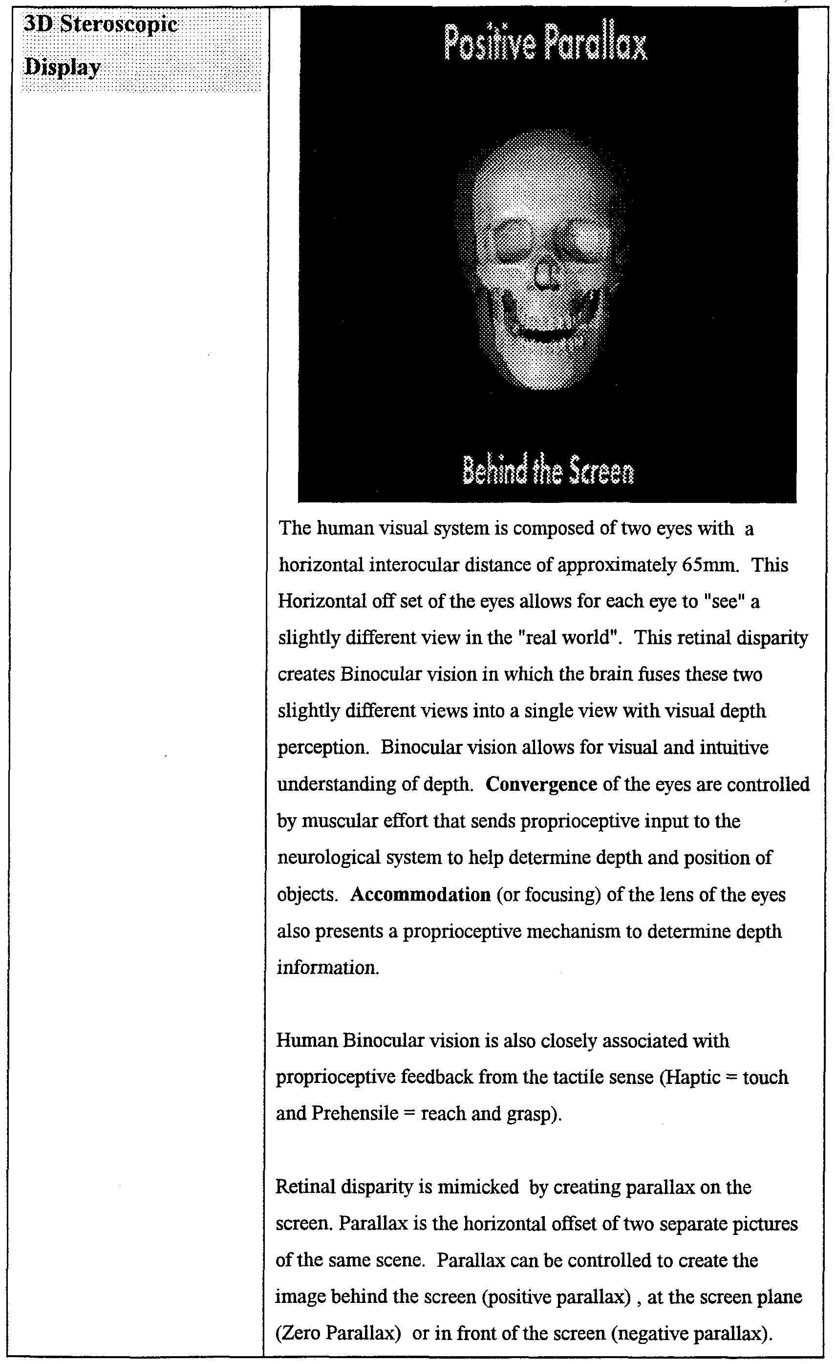
- the 3D display allows for the visualization of the 3D data base (created from photos, models, X-rays, etc). This 3D visualization allows for 1) Perspective 3D viewing with shading, shadowing and monocular depth cues. 2) Straight on 3D Stereoscopic viewing and 3) Ability to view the 3D data set in a 45 degree 3D Stereoscopic viewing mode (allows for 50% more visual information).
- the 3D display of the 3D data set can include the following information
- the user should be able to define a rotational pattern around one, two, or three axes, together or independently.
- Animation in perspective 3D and in Stereoscopic 3D (Example: open/closed animation to evaluate deviation on opening, asymmetry, etc. animate mandibular movements associated with jaw tracking).
- the 3D display should allow for user controlled transparency of facial soft tissue to show underlying teeth and skeletal structure relationship. Transparency should be controlled by a slide bar from 0% - 100% and have predefined 20%, 40%, 60%, 80%, for quick acquisition.
- Lighting of the 3D data set should be predefined to give the best brightness, contract, etc. Real time lighting changes should be possible to gain better 3D view. Especially important with 3D Stereoscopic viewing on high contrast areas as it gives poor results to the stereoscopic effect. In Stereoscopic mode the lighting should allow for the Stereopairs to be lighted the same. Eliminate difference in lighting of the two separate views , creates ghosting.
- a Reference plane should be available to show the drawing plane, etc. 15)
- zoom, magnify, scaling, set axis, split objects, move segments, trim, grasp objects should be available and user controlled
- the software 3D program should show the wireframe, quick render and full render of the 3D data set Also render a window should be available to render only an area of interest
- the 3D Display should use the photographs from which the wireframes are generated to create the photorealistic textures
- the camera setting should be predefined Other setting can be included as scene camera, director camera, pan, tilt, Roll, Dolly, etc.
- 3D display allow for import/export of Model files ( MDL, DXF, IGS, 3DS, other)
- the 3D display should allow for facial topography visualization and measurement Facial topography contours have certain patterns that differ from people considered “Beautiful” vs “Ugly” vs “Normal” Subtle differences in the nasal area, Zygomatic area (cheek bone), Lip contour, submental fold and chm area Facial topography will be more evident m stereoscopic 3-D visualization Features that are used to describe beauty
- Stereoscopic 3D imaging allows for all 3 planes of space to be viewed, simultaneously This is a clear and important difference between 3D Stereoscopic viewing and 3D perspective viewing
- stereoscopic 3D visualization is added to motion parallax (such as rotation of the object) there is an enhancement of visual depth
- Any 3D visual information can be created m a 3D Stereoscopic mode to further enhance to visual ability to understand 3D relationships of anatomy When motion parallax is also added even greater visual depth information is present
- the software program can create the appropriate "stereo pairs" for 3D Stereoscopic viewing. Lighting (brightness, contrast, shadows, etc), can be controlled.
- the software can create the appropriate parallax on the screen to create the stereoscopic image on the screen when viewed with the appropriate viewing lenses (anaglyph, polarized, field sequential).
- Anaglyph uses Red & Blue lenses so that each eye only sees the image it is suppose to see. There is some limitation on using colored images with the anaglyph mode.
- Stereo viewing of angular, linear, planes, angles, points, and volume is important.
- Full color can be done with anaglyph (synthonics) but problems do arise with red, blue and green colors that are part of the image. True full color is best seen with polarized or field sequential (LCD shutters).
- Field sequential can be 60 or 120Hz. The image flicker can only be eliminated with the 120 Hz.
- Another advantage of field sequential is tracking devices can be incorporated to allows the viewer to visualize the 3D scene from multiple viewing angles. The multiple viewing angle is an advantage over fixed viewing angle required by anaglyph or polarized viewing techniques.
- Landmark ID Landmarks can conespond with standard orthodontics landmarks, i.e., gonion, nasion, sella, pogonion, etc. These landmarks can be located in their normal position on the morphologically normal skeletal stock object and can be visually evident. These landmarks can be spatially associated to each other through the IMS data base functions.
- the spatially calibrated cephalometric views (H & M Associate software) can be overlaid on the stock object.
- the stock object will be customized to fit the cephalometric data by either drag and drop of a stock object landmark to the corresponding ceph. landmark (edited in all available projection views) or by digitizing the landmarks on the ceph and then making the association and customization from the stock object through the IMS data base.
- non-landmark cephalometric data may also be associated with the stock objects.
- the non-landmark data of most interest are the ridge crests (j.e., orbital rims, rim of the nasal fossa, external borders of the mandible, mandibular canal, sinuses margins etc.
- the stock objects provide a visual reference of the patients anatomy and the landmarks are the data base portion of the patient's file that describe the features that are unique for that individual. Therefore, only the landmark locations need to be stored in the IMS data base.
- the landmark locations can serve as a set of instructions for altering the stock objects.
- the transmission of patient landmark location and customizing the stock object at the receiver is more efficient method then transmitting a customized stock object.
- Use the IMS data base to compile landmark location data to be used to establish normative data for 3D cephalometric analysis and for upgrading the stock model.
- 2D Analysis and 2 D Normative Data A 2D orthodontic cephalometric analysis is based on comparison of the patients' data with 2D normative data bases that have existed for decades.
- 2D normative data bases include: Burlington growth study, Bolton/Broadbent, Rocky Mountain Data Systems, Michigan Growth Study, to name a few.
- 2D analysis include: Steiner Analysis, Downs Analysis, Ricketts, Tweed, Alabama, RMDS, Wits, Owens, etc.
- 2D template analyses are normative 2D visualizations that are overlayed
- the 2D normative data can be adjusted for sex, age, race, size, etc. and created into a graphical representation (template) of normative data for visual comparison.
- 3D analysis & 3D MedScape was founded on the premise to create, develop and Normative Data offer 3D & 3D Stereoscopic software products to the medical and dental professions. MedScape products will give the doctor the ability to diagnose and treatment plan their patients with three-dimensionally accurate models of anatomy (face, teeth & bones).
- 3D Normative Data This data will have to be developed through University research as this information is limited at this time. Grayson's arcticle in the AJO describes some 3-D growth patterns. Also Rick Jacobson gives some 3-D data in Jacobson's Book “Radiographic Cepahlometrics”. At this time, 3D analysis will have to be "projected” to a 2D format to compare to "narrative 2D data" since this is what exist at this time. These is some work being done in Australia and Canada on 3D MRI & Ceph data.
- 3D Analysis of Patient Data The traditional 2D landmarks, angles, planes, etc. can be viewed on the 3D model for comparison.
- the 3D model will add the advantage of being able to view asymmetries of the right & left side of the face, teeth, and skeletal structure. This is a critical area that is not assessed in "traditional" 2D analyses.
- the lingual concavity of the upper and lower incisors are related to the disclusion angle and the angle of the eminence. These should be congruent w/ each other.
- These functional components of TMJ function and dysfunction are important concepts that are critical for proper diagnosis.
- 3D analysis includes modeling of the critical anatomical areas & for the generic wireframes to adjust to overlay the patient's anatomy. A visual representation of "normal” can be overlayed over the patient's "abnormal" for direct comparison
- Custom Analysis The doctor will want to customize their analyses to include parts of various 2D & 3D analyses.
- the doctor can define which components of each to include.
- MedScape will allow the enduser to define, name, save and employ a custom analysis. This analysis can be implemented as a macro function.
- Growth forecasting has always been a goal of cephalometric diagnosis and treatment planning since the early days. It became popular with Ricketts introduction to RMDS growth forecasts.
- Lyle Johnston has developed a template that estimates "normal” growth "averages" in children.
- Burlington Growth Study is also available along with the Broadbent/Bolton study, Michigan study, & others. All of these are 2D.
- 3D growth forecasting is yet to be developed and will be a critical area of study and development.
- Time line tracking would allow the evaluation of progress over time.
- Patient's ALWAYS ask "When am I getting my braces off'.
- Accurate 3D evaluation of cooperation and growth or surgical plans with photos would be a GREAT stride forward.
- the software CEPHALOMETRIC simplifies the operator task of designating landmarks and LANDMARKS traces. For example when tracing an intensity edge in an image, as long as the user maintains the pointer in the general vicinity of the edge, the software automatically finds the edge and traces it without relying on precise pointer movement by the user.
- Patient Presentation Generic Presentation To demonstrate possible treatment options, patient education about orthodontics using a generic patient.
- Custom Presentation Demonstrate possible treatment options and outcomes using the patient's 3D anatomy.
- Arch Length Analysis Arch length analysis is a critical diagnostic measurement, as it and Tooth Size can determine diagnostic decisions of extractions of permanent Discrepancy Analysis teeth to correct certain orthodontic problems vs. non- extractions decisions.
- the teeth can fit within the supporting bone (alveolar bone) to the upper and lower jaw structure.
- the alveolar bone is the supporting bone that surrounds the roots of the teeth.
- the basal bone is the main supporting structure for the jaws.
- the basal bone of the lower jaw (mandible) is limited in size by its genetic potential and has limited ability for growth modification. There are possible growth modifications procedures, such as Functional Jaw Orthopedics that have some limited growth modification potential.
- the basal bone supports the alveolar bone which supports the teeth.
- the alveolar bone has the potential for adaptation to the positions of the teeth and can be modified as long as the teeth are kept within the limits of the basal bone.
- the upper jaw has the capability of increasing its transverse dimensions via "rapid Palatal Expansion” appliances. These types of orthopedic appliances not only change the alveolar bone shape and the size but can also change the dimension of the maxillary basal bone dimension due to "sutures" that exist in the upper jaw.
- the lower jaw does not have sutures associated with the mandibular skeletal structure.
- the maxilla is therefore capable of being increased in size to allow for more room form crowded or crooked teeth to be aligned into "normal" occlusal fit.
- Extraction vs. non-extraction of decisions have traditionally been based on the space requirements of the mandible due to its inability to be changed significantly.
- Significant arch discrepancy in the lower arch may require extraction of selected permanent teeth to resolve the crowding problem, the orthodontist can then decide which teeth can be removed in the upper jaw, if any, to create a "normal" occlusal fit of the teeth.
- the teeth can fit into this ideal occlusion when the mandible is in a CR or CO position.
- the Curve of Spee and the Curve of Wilson are three- dimensional relationships of the plane of occlusion when viewed from the lateral and frontal planes respectively.
- the analyses of these relationships of the teeth also are included in the decision making process of the orthodontist as far as the extraction vs. non-extraction treatment decisions.
- As the Curves "level" out the teeth could be positioned where there is no bone support leading to periodontal (gum) problems. Recession and/or alveolar bone loss could occur if not properly controlled mechanically.
- the doctor can evaluate ALL 3D requirements of each arch, TMJ, bone configuration, etc. These include: 1. the sagittal dimensions (length), 2. the transverse dimension (width), and 3. The vertical dimension (height).
- Tooth Size Discrepancy The size of the individual teeth as they are positioned around the "Caternary" type curve of the arch, take upo space. The relative sizes of each tooth type (molars, bicuspids, cuspids, incisors) can be interrelated appropriately or the occlusion of the teeth will not fit properly at the end of treatment. If a discrepancy exists in the relative sizes of certain teeth in the arch, then a so called “Bolton Tooth Size Discrepancy" exists. This tooth size discrepancy can also effect the fit of the occlusion between the opposing arches.
- Bolton tooth size discrepancies are created when there is a mismatch in the size of teeth within the respective arch. This creates a problem of alignment and proper fit of the occlusion. Knowing these discrepancies prior to treatment is critical for orthodontic diagnosis. Limitations in treatment need to be related to the patient as apart of their informed consent. Small lateral incisors, abnormal shape & form, congenital absence are a few problems that create a compromised end result. Restorative dental procedures to correct some of these discrepancies, need to be planned prior to treatment so the patient will be informed and expect follow up care. Relapse of teeth after orthodontic correction is a major consideration in orthodontic therapy. Many elaborate treatment alternative have been devised to control relapse. The ability to three-dimensionally diagnose and treatment plan a patient may lead to improved retention of orthodontically treated cases.
- the Curve of Spee is a curve of the occlusal plane as seen from the lateral view.
- the Curve of Wilson is the curve or construction of the occlusal plane as view from the frontal.
- the treatment of these two “curves” are important as to the eventual final result of the occlusion.
- Orthodontist usually "flatten" these curves during treatment for occlusal correction. Uprighting the Curve of Wilson can lead to increased arch length and help to gain space for crowded teeth, up to the limit of the alveolar bone, cortical bone, and basal bone.
- Leveling the Curve of Spee is a routine orthodontic biomechanical effect of treatment.
- Each tooth coordinate measurement represents a point in space.
- the total arch circumference is the magnitude of the summation of all vectors connecting their points and given by:
- Ct ' (X I -X J ) 2 + (Y 1 -Y J ) 2 + (Z,- Z J ) 2 represents the total arch circumference in 3D space and N is the number of teeth measured.
- the planer projection of the total arch circumference is calculated using a similar method except the depth coordinate (Z,) i.e., depth of Spee is excluded.
- C p represents the planer projection of the total arch circumference to a lateral 2D projected view.
- Asymmetry analysis defines the morphology differences between the right and left halves the mandible, maxilla and other regions of the skeleton.
- the symmetry of these structures should be determined through the use of landmark groupings.
- the procedure may include determination of the sagittal plane midline of the patient by utilizing identifying midline landmarks.
- the sagittal plane midline can be used to define the right and left halves of the patient.
- the simplest symmetry analysis would be begin with the superimposition of the right and left halves of the mandible utilizing the sagittal plane midline reference as the registration plane.
- the quantification of the asymmetry would be to compare the x,y,z differences in location of the corresponding right and left landmarks and to compare the location of these landmarks to the normal landmark location (by standard deviation) .
- This type of analysis would allow the end user to quantify the amount of asymmetry and direct the end user to etiology of the asymmetry. For example, when the mandible is asymmetric then it is safe to assume that one side is too small or the conttalateral side is too large. Comparison of the patient data with normal data would allow the clinician to determine which side was abnormal. Knowledge of the etiology of asymmetry may be critical in controlling or predicting the outcome of treatment.
- Additional analysis may include a normalization of the 3-D data to the standard ABO 2-D views and performing an analysis using existing analysis models. Tools may be created to allow the end user to create a symmetry analysis.
- the spatially calibrated cephalometric views can be overlaid on the stock object.
- the stock object will be customized to fit the cephalometric data by either drag and drop of a stock object landmark to the corresponding ceph. landmark (edited in all available projection views) or by digitizing the landmarks on the ceph and then making the association and customization of the stock object through the IMS data base. A combination of the two customization methods can be used.
- non- landmark cephalometric data may also be associated with the stock objects.
- the non-landmark data of most interest are the ridge crests (i.e., orbital rims, rim of the nasal fossa, external borders of the mandible, etc. These same methods may be employed for other stock objects, such as, the teeth, TMJs etc.
- the stock objects are a graphical representation of normal. These normal values for landmark location have been determined through an analysis of the landmark locations on many patients (Burlington study) and have been sorted by age and sex of the patient. Deviations from normal can be analyzed and statistically grouped as a standard deviation from normal. Through the use of the IMS data base we can define normal and the standard deviations from normal for individual landmarks and landmark groupings.
- the IMS data base will perform an assessment of landmarks locations and groupings of landmarks by compare the patient data to normal data through look up tables (LUT) contained in the IMS data base. After this analysis the computer can highlight in color on
- Gnathological Normal refers to the cusp fossa spatial relationships, the tooth to tooth relationships among and between the maxillary and mandibular teeth and tooth position relative to the supporting alveolarO and basal bone.
- the tooth and its 3-D location and spatial orientation relative to the tooth long axis can be defined through tracking of landmarks located on the root apices or apex, cusp tip(s) or incisal edge and the mesial and distal greatest heights of contour. This specialized segmentation of teeth allows them to function as objects.
- a database that represents gnathological normal teeth can and be used when rendering the stock object teeth in combination with the skeleton. Deviations from the gnathological normal can be described in a similar fashion to the method used for cephalometric analysis.
- a pseudo-colored visual display of the anatomy that falls outside the statistical normal will facilitate a quick identification of abnormal tooth position, etc.
- the airway can be divided into the nasal airway, the nasal pharynx and oropharynx.
- the nasal airway begins at the anterior opening of the nasal passage and ends at the posterior margin of the nasal fossa.
- the nasopharynx begins at the posterior margin of the nasal fossa and ends at the most inferior area of the soft palate.
- the oropharynx begins at the inferior margin of the soft palate and ends at the superior margin of the valecula.
- An airway analysis includes a mathematical description of nasal septum symmetry about the
- Three basic imaging software modules (Sculptor, Clinician and Executor) comprise the Acuscape suite of software designed for the medical use.
- the Sculptor is used at an image processing center (server) and passes the acquired images and measurement files (.sci files) to the Clinician user (client) for the generation of the .pro file and subsequent use.
- Sculptor Module Images are acquired directly into a patient session file from input devices that include digital cameras, flat bed scanners, x-ray sensors, etc. or from image storage files. An Acuscape image calibration frame is worn during image acquisition and shadows of the calibration markers are
- the images are first spatially calibrated and a patient centric co-ordinate
- This co-ordinate system is transferred to the images.
- This co-ordinate system is adjusted or optimized to best fit the patients anatomy. Part of this adjustment superimposes the y-z plane of the co-ordinate system to superimpose on the patient's mid-
- the subsequent measurements store data utilizing this constructed co-ordinate system.
- the calibrated images can be stored by the executor or displayed and measured. Multiple images or image sets can be
- measurements can be performed as point, closed loop trace and linear trace measurements.
- the measurement routine occurs simultaneous on all images
- the selected image is measured and a corresponding
- epipolar line is constructed on the adjacent images to assist with locating the
- the z,y and z locations of all of the measurement points and lines (series of points) are stored in a measurement file.
- measurement files are converted to an export file that contains all .jpg images
- the .sci files contain the calibration information, camera parameters and the x,y and z locations of all traces and landmarks.
- Cross calibration refers to calibrating multiple images and image types to the same 3D co-ordinate system. These images can include but are not limited
- the Sculptor will be used to calibrate and measure the images (spatially, color or gray scale value).
- Executor Module This module works in the background to manage images for the Sculptor and Clinician modules. This is a patient centric relational data
- Patient file transport files contain the .jpg images and an .sci file.
- the .sci file is
- the module is intended to exist primarily in the doctor's
Abstract
Description


Claims
Priority Applications (3)
| Application Number | Priority Date | Filing Date | Title |
|---|---|---|---|
| CA002296274A CA2296274A1 (en) | 1998-05-13 | 1999-05-13 | Method and apparatus for generating 3d models from medical images |
| EP99924217A EP1027681A4 (en) | 1998-05-13 | 1999-05-13 | Method and apparatus for generating 3d models from medical images |
| AU40769/99A AU4076999A (en) | 1998-05-13 | 1999-05-13 | Method and apparatus for generating 3d models from medical images |
Applications Claiming Priority (2)
| Application Number | Priority Date | Filing Date | Title |
|---|---|---|---|
| US8537298P | 1998-05-13 | 1998-05-13 | |
| US60/085,372 | 1998-05-13 |
Publications (1)
| Publication Number | Publication Date |
|---|---|
| WO1999059106A1 true WO1999059106A1 (en) | 1999-11-18 |
Family
ID=22191192
Family Applications (1)
| Application Number | Title | Priority Date | Filing Date |
|---|---|---|---|
| PCT/US1999/010566 WO1999059106A1 (en) | 1998-05-13 | 1999-05-13 | Method and apparatus for generating 3d models from medical images |
Country Status (4)
| Country | Link |
|---|---|
| EP (1) | EP1027681A4 (en) |
| AU (1) | AU4076999A (en) |
| CA (1) | CA2296274A1 (en) |
| WO (1) | WO1999059106A1 (en) |
Cited By (139)
| Publication number | Priority date | Publication date | Assignee | Title |
|---|---|---|---|---|
| EP1348393A1 (en) * | 2002-03-27 | 2003-10-01 | BrainLAB AG | Medical navigation or pre-operative treatment planning supported by generic patient data |
| EP1348394A1 (en) | 2002-03-27 | 2003-10-01 | BrainLAB AG | Planning or navigation assistance by generic obtained patient data with two-dimensional adaptation |
| WO2003061501A3 (en) * | 2002-01-16 | 2003-10-16 | Orthosoft Inc | Method and apparatus for reconstructing bone surfaces during surgery |
| EP1127545A3 (en) * | 2000-02-26 | 2004-05-06 | Philips Intellectual Property & Standards GmbH | Procedure for locating objects in radiotherapy |
| EP1417931A1 (en) * | 2002-11-05 | 2004-05-12 | EASTMAN KODAK COMPANY (a New Jersey corporation) | Method for automatically producing true size radiographic image |
| WO2004095372A1 (en) * | 2003-04-22 | 2004-11-04 | Provincia Italiana Della Congregazione Dei Figli Dell'immacolata Concezione - Instituto Dermopatico Dell'immacolata | Automatic detection of skin lesions |
| WO2004098378A2 (en) | 2003-05-02 | 2004-11-18 | Orametrix, Inc. | Unified workstation for virtual craniofacial diagnosis treatment planning and therapeutics |
| EP1570800A1 (en) * | 2004-03-01 | 2005-09-07 | BrainLAB AG | Method and device for determining the symmetrical plane of a three dimensional object |
| WO2006092600A1 (en) | 2005-03-01 | 2006-09-08 | Kings College London | Surgical planning |
| WO2006116488A2 (en) * | 2005-04-25 | 2006-11-02 | Xoran Technologies, Inc. | Ct system with synthetic view generation |
| WO2007017642A1 (en) * | 2005-08-05 | 2007-02-15 | Depuy Orthopädie Gmbh | Computer assisted surgery system |
| CN1308897C (en) * | 2002-09-15 | 2007-04-04 | 深圳市泛友科技有限公司 | Method for forming new three-dimensional model using a group of two-dimensional photos and three-dimensional library |
| EP1803413A2 (en) | 2005-12-30 | 2007-07-04 | DePuy Products, Inc. | Magnetic sensor array for bone registration in computer-assisted orthopaedic surgery |
| WO2004044787A3 (en) * | 2002-11-11 | 2007-11-15 | Albert Mehl | Method for producing denture parts or for tooth restoration using electronic dental representations |
| EP1959391A1 (en) * | 2007-02-13 | 2008-08-20 | BrainLAB AG | Determination of the three dimensional contour path of an anatomical structure |
| EP1982652A1 (en) * | 2007-04-20 | 2008-10-22 | Medicim NV | Method for deriving shape information |
| WO2008129360A1 (en) * | 2007-04-19 | 2008-10-30 | Damvig Develop Future Aps | A method for the manufacturing of a reproduction of an encapsulated three-dimensional physical object and objects obtained by the method |
| WO2009006303A2 (en) * | 2007-06-29 | 2009-01-08 | 3M Innovative Properties Company | Video-assisted margin marking for dental models |
| US7477776B2 (en) | 2004-03-01 | 2009-01-13 | Brainlab Ag | Method and apparatus for determining a plane of symmetry of a three-dimensional object |
| US7715602B2 (en) | 2002-01-18 | 2010-05-11 | Orthosoft Inc. | Method and apparatus for reconstructing bone surfaces during surgery |
| US7720519B2 (en) | 2002-10-17 | 2010-05-18 | Elekta Neuromag Oy | Method for three-dimensional modeling of the skull and internal structures thereof |
| ITBO20090111A1 (en) * | 2009-02-26 | 2010-08-27 | Paolo Fiorini | METHOD AND SURGICAL TRAINING APPARATUS |
| US7787932B2 (en) | 2002-04-26 | 2010-08-31 | Brainlab Ag | Planning and navigation assistance using two-dimensionally adapted generic and detected patient data |
| US7873403B2 (en) | 2003-07-15 | 2011-01-18 | Brainlab Ag | Method and device for determining a three-dimensional form of a body from two-dimensional projection images |
| EP2039321A3 (en) * | 2000-11-08 | 2011-04-27 | Institut Straumann AG | Surface recording and generation |
| CN102159155A (en) * | 2008-09-18 | 2011-08-17 | 3形状股份有限公司 | Tools for customized design of dental restorations |
| US8068648B2 (en) | 2006-12-21 | 2011-11-29 | Depuy Products, Inc. | Method and system for registering a bone of a patient with a computer assisted orthopaedic surgery system |
| WO2012117122A1 (en) * | 2011-03-01 | 2012-09-07 | Dolphin Imaging Systems, Llc | System and method for generating profile change using cephalometric monitoring data |
| US8265949B2 (en) | 2007-09-27 | 2012-09-11 | Depuy Products, Inc. | Customized patient surgical plan |
| US20120259592A1 (en) * | 2011-04-07 | 2012-10-11 | Dolphin Imaging Systems, Llc | System and Method for Three-Dimensional Maxillofacial Surgical Simulation and Planning |
| US8343159B2 (en) | 2007-09-30 | 2013-01-01 | Depuy Products, Inc. | Orthopaedic bone saw and method of use thereof |
| US8357111B2 (en) | 2007-09-30 | 2013-01-22 | Depuy Products, Inc. | Method and system for designing patient-specific orthopaedic surgical instruments |
| TWI387315B (en) * | 2010-06-29 | 2013-02-21 | Acer Inc | Three dimensional liquid crystal shutter glasses |
| US8417004B2 (en) | 2011-04-07 | 2013-04-09 | Dolphin Imaging Systems, Llc | System and method for simulated linearization of curved surface |
| US8858561B2 (en) | 2006-06-09 | 2014-10-14 | Blomet Manufacturing, LLC | Patient-specific alignment guide |
| US8862200B2 (en) | 2005-12-30 | 2014-10-14 | DePuy Synthes Products, LLC | Method for determining a position of a magnetic source |
| US8868199B2 (en) | 2012-08-31 | 2014-10-21 | Greatbatch Ltd. | System and method of compressing medical maps for pulse generator or database storage |
| US8864769B2 (en) | 2006-02-27 | 2014-10-21 | Biomet Manufacturing, Llc | Alignment guides with patient-specific anchoring elements |
| US8903496B2 (en) | 2012-08-31 | 2014-12-02 | Greatbatch Ltd. | Clinician programming system and method |
| US8900244B2 (en) | 2006-02-27 | 2014-12-02 | Biomet Manufacturing, Llc | Patient-specific acetabular guide and method |
| US8903530B2 (en) | 2011-06-06 | 2014-12-02 | Biomet Manufacturing, Llc | Pre-operative planning and manufacturing method for orthopedic procedure |
| US8956364B2 (en) | 2011-04-29 | 2015-02-17 | Biomet Manufacturing, Llc | Patient-specific partial knee guides and other instruments |
| WO2015027196A1 (en) * | 2013-08-22 | 2015-02-26 | Bespoke, Inc. | Method and system to create custom products |
| US8979936B2 (en) | 2006-06-09 | 2015-03-17 | Biomet Manufacturing, Llc | Patient-modified implant |
| US8983616B2 (en) | 2012-09-05 | 2015-03-17 | Greatbatch Ltd. | Method and system for associating patient records with pulse generators |
| US9005297B2 (en) | 2006-02-27 | 2015-04-14 | Biomet Manufacturing, Llc | Patient-specific elbow guides and associated methods |
| US9053563B2 (en) | 2011-02-11 | 2015-06-09 | E4 Endeavors, Inc. | System and method for modeling a biopsy specimen |
| US9060788B2 (en) | 2012-12-11 | 2015-06-23 | Biomet Manufacturing, Llc | Patient-specific acetabular guide for anterior approach |
| US9066727B2 (en) | 2010-03-04 | 2015-06-30 | Materialise Nv | Patient-specific computed tomography guides |
| US9066734B2 (en) | 2011-08-31 | 2015-06-30 | Biomet Manufacturing, Llc | Patient-specific sacroiliac guides and associated methods |
| US9084618B2 (en) | 2011-06-13 | 2015-07-21 | Biomet Manufacturing, Llc | Drill guides for confirming alignment of patient-specific alignment guides |
| US9113971B2 (en) | 2006-02-27 | 2015-08-25 | Biomet Manufacturing, Llc | Femoral acetabular impingement guide |
| US9173666B2 (en) | 2011-07-01 | 2015-11-03 | Biomet Manufacturing, Llc | Patient-specific-bone-cutting guidance instruments and methods |
| US9173661B2 (en) | 2006-02-27 | 2015-11-03 | Biomet Manufacturing, Llc | Patient specific alignment guide with cutting surface and laser indicator |
| US9180302B2 (en) | 2012-08-31 | 2015-11-10 | Greatbatch Ltd. | Touch screen finger position indicator for a spinal cord stimulation programming device |
| US9204977B2 (en) | 2012-12-11 | 2015-12-08 | Biomet Manufacturing, Llc | Patient-specific acetabular guide for anterior approach |
| US9237950B2 (en) | 2012-02-02 | 2016-01-19 | Biomet Manufacturing, Llc | Implant with patient-specific porous structure |
| US9241745B2 (en) | 2011-03-07 | 2016-01-26 | Biomet Manufacturing, Llc | Patient-specific femoral version guide |
| US9259577B2 (en) | 2012-08-31 | 2016-02-16 | Greatbatch Ltd. | Method and system of quick neurostimulation electrode configuration and positioning |
| US9271744B2 (en) | 2010-09-29 | 2016-03-01 | Biomet Manufacturing, Llc | Patient-specific guide for partial acetabular socket replacement |
| US9289253B2 (en) | 2006-02-27 | 2016-03-22 | Biomet Manufacturing, Llc | Patient-specific shoulder guide |
| US9295497B2 (en) | 2011-08-31 | 2016-03-29 | Biomet Manufacturing, Llc | Patient-specific sacroiliac and pedicle guides |
| US9301812B2 (en) | 2011-10-27 | 2016-04-05 | Biomet Manufacturing, Llc | Methods for patient-specific shoulder arthroplasty |
| US9339278B2 (en) | 2006-02-27 | 2016-05-17 | Biomet Manufacturing, Llc | Patient-specific acetabular guides and associated instruments |
| US9345548B2 (en) | 2006-02-27 | 2016-05-24 | Biomet Manufacturing, Llc | Patient-specific pre-operative planning |
| US9351743B2 (en) | 2011-10-27 | 2016-05-31 | Biomet Manufacturing, Llc | Patient-specific glenoid guides |
| US9375582B2 (en) | 2012-08-31 | 2016-06-28 | Nuvectra Corporation | Touch screen safety controls for clinician programmer |
| US9386993B2 (en) | 2011-09-29 | 2016-07-12 | Biomet Manufacturing, Llc | Patient-specific femoroacetabular impingement instruments and methods |
| US9393028B2 (en) | 2009-08-13 | 2016-07-19 | Biomet Manufacturing, Llc | Device for the resection of bones, method for producing such a device, endoprosthesis suited for this purpose and method for producing such an endoprosthesis |
| US9408616B2 (en) | 2014-05-12 | 2016-08-09 | Biomet Manufacturing, Llc | Humeral cut guide |
| US9427320B2 (en) | 2011-08-04 | 2016-08-30 | Biomet Manufacturing, Llc | Patient-specific pelvic implants for acetabular reconstruction |
| US9445907B2 (en) | 2011-03-07 | 2016-09-20 | Biomet Manufacturing, Llc | Patient-specific tools and implants |
| US9451973B2 (en) | 2011-10-27 | 2016-09-27 | Biomet Manufacturing, Llc | Patient specific glenoid guide |
| US9456833B2 (en) | 2010-02-26 | 2016-10-04 | Biomet Sports Medicine, Llc | Patient-specific osteotomy devices and methods |
| US9471753B2 (en) | 2012-08-31 | 2016-10-18 | Nuvectra Corporation | Programming and virtual reality representation of stimulation parameter Groups |
| US9474539B2 (en) | 2011-04-29 | 2016-10-25 | Biomet Manufacturing, Llc | Patient-specific convertible guides |
| US9480490B2 (en) | 2006-02-27 | 2016-11-01 | Biomet Manufacturing, Llc | Patient-specific guides |
| US9480580B2 (en) | 2006-02-27 | 2016-11-01 | Biomet Manufacturing, Llc | Patient-specific acetabular alignment guides |
| US9498233B2 (en) | 2013-03-13 | 2016-11-22 | Biomet Manufacturing, Llc. | Universal acetabular guide and associated hardware |
| US9507912B2 (en) | 2012-08-31 | 2016-11-29 | Nuvectra Corporation | Method and system of simulating a pulse generator on a clinician programmer |
| US9517145B2 (en) | 2013-03-15 | 2016-12-13 | Biomet Manufacturing, Llc | Guide alignment system and method |
| US9522010B2 (en) | 2006-02-27 | 2016-12-20 | Biomet Manufacturing, Llc | Patient-specific orthopedic instruments |
| WO2017011337A1 (en) * | 2015-07-10 | 2017-01-19 | Quantant Technology Inc. | Remote cloud based medical image sharing and rendering |
| US9554910B2 (en) | 2011-10-27 | 2017-01-31 | Biomet Manufacturing, Llc | Patient-specific glenoid guide and implants |
| US9561040B2 (en) | 2014-06-03 | 2017-02-07 | Biomet Manufacturing, Llc | Patient-specific glenoid depth control |
| US9579107B2 (en) | 2013-03-12 | 2017-02-28 | Biomet Manufacturing, Llc | Multi-point fit for patient specific guide |
| US9594877B2 (en) | 2012-08-31 | 2017-03-14 | Nuvectra Corporation | Virtual reality representation of medical devices |
| US9615788B2 (en) | 2012-08-31 | 2017-04-11 | Nuvectra Corporation | Method and system of producing 2D representations of 3D pain and stimulation maps and implant models on a clinician programmer |
| US9662127B2 (en) | 2006-02-27 | 2017-05-30 | Biomet Manufacturing, Llc | Patient-specific acetabular guides and associated instruments |
| US9662216B2 (en) | 2006-02-27 | 2017-05-30 | Biomet Manufacturing, Llc | Patient-specific hip joint devices |
| US9675400B2 (en) | 2011-04-19 | 2017-06-13 | Biomet Manufacturing, Llc | Patient-specific fracture fixation instrumentation and method |
| US9717510B2 (en) | 2011-04-15 | 2017-08-01 | Biomet Manufacturing, Llc | Patient-specific numerically controlled instrument |
| FR3048541A1 (en) * | 2016-03-01 | 2017-09-08 | Lyra Holding | VIRTUAL CHANGE OF A PERSON'S TOOTH |
| US9767255B2 (en) | 2012-09-05 | 2017-09-19 | Nuvectra Corporation | Predefined input for clinician programmer data entry |
| US9795399B2 (en) | 2006-06-09 | 2017-10-24 | Biomet Manufacturing, Llc | Patient-specific knee alignment guide and associated method |
| US9820868B2 (en) | 2015-03-30 | 2017-11-21 | Biomet Manufacturing, Llc | Method and apparatus for a pin apparatus |
| US9826981B2 (en) | 2013-03-13 | 2017-11-28 | Biomet Manufacturing, Llc | Tangential fit of patient-specific guides |
| US9826994B2 (en) | 2014-09-29 | 2017-11-28 | Biomet Manufacturing, Llc | Adjustable glenoid pin insertion guide |
| US9833245B2 (en) | 2014-09-29 | 2017-12-05 | Biomet Sports Medicine, Llc | Tibial tubercule osteotomy |
| US9839438B2 (en) | 2013-03-11 | 2017-12-12 | Biomet Manufacturing, Llc | Patient-specific glenoid guide with a reusable guide holder |
| US9839436B2 (en) | 2014-06-03 | 2017-12-12 | Biomet Manufacturing, Llc | Patient-specific glenoid depth control |
| US9861387B2 (en) | 2006-06-09 | 2018-01-09 | Biomet Manufacturing, Llc | Patient-specific knee alignment guide and associated method |
| US9907659B2 (en) | 2007-04-17 | 2018-03-06 | Biomet Manufacturing, Llc | Method and apparatus for manufacturing an implant |
| US9918740B2 (en) | 2006-02-27 | 2018-03-20 | Biomet Manufacturing, Llc | Backup surgical instrument system and method |
| US9968376B2 (en) | 2010-11-29 | 2018-05-15 | Biomet Manufacturing, Llc | Patient-specific orthopedic instruments |
| US10159498B2 (en) | 2008-04-16 | 2018-12-25 | Biomet Manufacturing, Llc | Method and apparatus for manufacturing an implant |
| US10226262B2 (en) | 2015-06-25 | 2019-03-12 | Biomet Manufacturing, Llc | Patient-specific humeral guide designs |
| WO2019068085A1 (en) * | 2017-09-29 | 2019-04-04 | K2M, Inc. | Systems and methods for simulating spine and skeletal system pathologies |
| US10278711B2 (en) | 2006-02-27 | 2019-05-07 | Biomet Manufacturing, Llc | Patient-specific femoral guide |
| US10282488B2 (en) | 2014-04-25 | 2019-05-07 | Biomet Manufacturing, Llc | HTO guide with optional guided ACL/PCL tunnels |
| EP2861180B1 (en) | 2012-06-15 | 2019-08-07 | Vita Zahnfabrik H. Rauter GmbH & Co. KG | Method for preparing a partial or full dental prosthesis |
| US10438351B2 (en) | 2017-12-20 | 2019-10-08 | International Business Machines Corporation | Generating simulated photographic anatomical slices |
| US10492798B2 (en) | 2011-07-01 | 2019-12-03 | Biomet Manufacturing, Llc | Backup kit for a patient-specific arthroplasty kit assembly |
| IT201800006261A1 (en) * | 2018-06-13 | 2019-12-13 | PROCEDURE FOR MAKING AN ANATOMICAL PROTOTYPE | |
| US10521908B2 (en) | 2017-12-20 | 2019-12-31 | International Business Machines Corporation | User interface for displaying simulated anatomical photographs |
| DE10148412B4 (en) * | 2000-10-11 | 2020-01-16 | Palodex Group Oy | Method and device for imaging the head area of a patient |
| US10568647B2 (en) | 2015-06-25 | 2020-02-25 | Biomet Manufacturing, Llc | Patient-specific humeral guide designs |
| US10603179B2 (en) | 2006-02-27 | 2020-03-31 | Biomet Manufacturing, Llc | Patient-specific augments |
| US10614570B2 (en) | 2017-12-20 | 2020-04-07 | International Business Machines Corporation | Medical image exam navigation using simulated anatomical photographs |
| CN111052186A (en) * | 2017-08-08 | 2020-04-21 | 维申Rt 有限公司 | Method and apparatus for measuring accuracy of a model generated by a patient monitoring system |
| US10668276B2 (en) | 2012-08-31 | 2020-06-02 | Cirtec Medical Corp. | Method and system of bracketing stimulation parameters on clinician programmers |
| US10722310B2 (en) | 2017-03-13 | 2020-07-28 | Zimmer Biomet CMF and Thoracic, LLC | Virtual surgery planning system and method |
| US10734116B2 (en) | 2011-10-04 | 2020-08-04 | Quantant Technology, Inc. | Remote cloud based medical image sharing and rendering semi-automated or fully automated network and/or web-based, 3D and/or 4D imaging of anatomy for training, rehearsing and/or conducting medical procedures, using multiple standard X-ray and/or other imaging projections, without a need for special hardware and/or systems and/or pre-processing/analysis of a captured image data |
| US10758321B2 (en) | 2008-05-23 | 2020-09-01 | Align Technology, Inc. | Smile designer |
| WO2020222169A1 (en) | 2019-05-02 | 2020-11-05 | DePuy Synthes Products, Inc. | Orthopaedic implant placement system and method |
| US10874487B2 (en) | 2003-02-26 | 2020-12-29 | Align Technology, Inc. | Systems and methods for fabricating a dental template |
| US10892058B2 (en) | 2017-09-29 | 2021-01-12 | K2M, Inc. | Systems and methods for simulating spine and skeletal system pathologies |
| US11000334B1 (en) | 2017-07-12 | 2021-05-11 | K2M, Inc. | Systems and methods for modeling spines and treating spines based on spine models |
| US11051829B2 (en) | 2018-06-26 | 2021-07-06 | DePuy Synthes Products, Inc. | Customized patient-specific orthopaedic surgical instrument |
| US11147652B2 (en) | 2014-11-13 | 2021-10-19 | Align Technology, Inc. | Method for tracking, predicting, and proactively correcting malocclusion and related issues |
| US11179165B2 (en) | 2013-10-21 | 2021-11-23 | Biomet Manufacturing, Llc | Ligament guide registration |
| US11207135B2 (en) | 2017-07-12 | 2021-12-28 | K2M, Inc. | Systems and methods for modeling spines and treating spines based on spine models |
| CN114596289A (en) * | 2022-03-11 | 2022-06-07 | 北京朗视仪器股份有限公司 | Mouth point detection method based on soft tissue contour line sampling points |
| US11419726B2 (en) | 2012-01-20 | 2022-08-23 | Conformis, Inc. | Systems and methods for manufacturing, preparation and use of blanks in orthopedic implants |
| US11419618B2 (en) | 2011-10-27 | 2022-08-23 | Biomet Manufacturing, Llc | Patient-specific glenoid guides |
| US11636650B2 (en) | 2018-09-24 | 2023-04-25 | K2M, Inc. | System and method for isolating anatomical features in computerized tomography data |
| US11707327B2 (en) | 2017-07-12 | 2023-07-25 | K2M, Inc. | Systems and methods for modeling spines and treating spines based on spine models |
| WO2023156447A1 (en) * | 2022-02-18 | 2023-08-24 | 3Shape A/S | Method of generating a training data set for determining periodontal structures of a patient |
| US11950786B2 (en) | 2021-07-02 | 2024-04-09 | DePuy Synthes Products, Inc. | Customized patient-specific orthopaedic surgical instrument |
Families Citing this family (2)
| Publication number | Priority date | Publication date | Assignee | Title |
|---|---|---|---|---|
| US11589949B1 (en) * | 2018-04-05 | 2023-02-28 | MirrorMe3D, LLC | System and methods of creating a 3D medical representation for use in performing reconstructive surgeries |
| CN110060287B (en) * | 2019-04-26 | 2021-06-15 | 北京迈格威科技有限公司 | Face image nose shaping method and device |
Citations (24)
| Publication number | Priority date | Publication date | Assignee | Title |
|---|---|---|---|---|
| US4945914A (en) * | 1987-11-10 | 1990-08-07 | Allen George S | Method and apparatus for providing related images over time of a portion of the anatomy using at least four fiducial implants |
| US5005578A (en) * | 1986-12-16 | 1991-04-09 | Sam Technology, Inc. | Three-dimensional magnetic resonance image distortion correction method and system |
| US5099846A (en) * | 1988-12-23 | 1992-03-31 | Hardy Tyrone L | Method and apparatus for video presentation from a variety of scanner imaging sources |
| WO1992006645A1 (en) * | 1990-10-19 | 1992-04-30 | St. Louis University | Surgical probe locating system for head use |
| US5257203A (en) * | 1989-06-09 | 1993-10-26 | Regents Of The University Of Minnesota | Method and apparatus for manipulating computer-based representations of objects of complex and unique geometry |
| US5274551A (en) * | 1991-11-29 | 1993-12-28 | General Electric Company | Method and apparatus for real-time navigation assist in interventional radiological procedures |
| US5273429A (en) * | 1992-04-03 | 1993-12-28 | Foster-Miller, Inc. | Method and apparatus for modeling a dental prosthesis |
| US5278756A (en) * | 1989-01-24 | 1994-01-11 | Dolphin Imaging Systems | Method and apparatus for generating cephalometric images |
| US5356294A (en) * | 1993-07-30 | 1994-10-18 | Wataru Odomo | Dental diagnostic and instructional apparatus |
| US5490221A (en) * | 1990-10-02 | 1996-02-06 | The United States Of America As Represented By The Administrator Of The National Aeronautics And Space Administration | Digital data registration and differencing compression system |
| WO1996010949A1 (en) * | 1994-10-07 | 1996-04-18 | Medical Media Systems | Video-based surgical targeting system |
| JPH08335278A (en) * | 1995-04-05 | 1996-12-17 | Hitachi Medical Corp | Method and device for tomographic image interpolation |
| WO1997003601A1 (en) * | 1995-07-24 | 1997-02-06 | Interact Medical Technologies Corporation | Anatomical visualization system |
| US5608774A (en) * | 1995-06-23 | 1997-03-04 | Science Applications International Corporation | Portable, digital X-ray apparatus for producing, storing, and displaying electronic radioscopic images |
| WO1997023164A1 (en) * | 1995-12-21 | 1997-07-03 | Siemens Corporate Research, Inc. | Calibration system and method for x-ray geometry |
| US5737506A (en) * | 1995-06-01 | 1998-04-07 | Medical Media Systems | Anatomical visualization system |
| US5740802A (en) * | 1993-04-20 | 1998-04-21 | General Electric Company | Computer graphic and live video system for enhancing visualization of body structures during surgery |
| US5742291A (en) * | 1995-05-09 | 1998-04-21 | Synthonics Incorporated | Method and apparatus for creation of three-dimensional wire frames |
| US5769861A (en) * | 1995-09-28 | 1998-06-23 | Brainlab Med. Computersysteme Gmbh | Method and devices for localizing an instrument |
| US5798924A (en) * | 1993-12-04 | 1998-08-25 | Eufinger; Harald | Process for producing endoprostheses |
| US5889524A (en) * | 1995-09-11 | 1999-03-30 | University Of Washington | Reconstruction of three-dimensional objects using labeled piecewise smooth subdivision surfaces |
| US5910107A (en) * | 1993-12-29 | 1999-06-08 | First Opinion Corporation | Computerized medical diagnostic and treatment advice method |
| US5920660A (en) * | 1995-04-05 | 1999-07-06 | Hitachi Medical Corporation | Tomogram interpolation method for executing interpolation calculation by using pixel values on projection line |
| US5926568A (en) * | 1997-06-30 | 1999-07-20 | The University Of North Carolina At Chapel Hill | Image object matching using core analysis and deformable shape loci |
-
1999
- 1999-05-13 EP EP99924217A patent/EP1027681A4/en not_active Withdrawn
- 1999-05-13 CA CA002296274A patent/CA2296274A1/en not_active Abandoned
- 1999-05-13 AU AU40769/99A patent/AU4076999A/en not_active Abandoned
- 1999-05-13 WO PCT/US1999/010566 patent/WO1999059106A1/en not_active Application Discontinuation
Patent Citations (25)
| Publication number | Priority date | Publication date | Assignee | Title |
|---|---|---|---|---|
| US5005578A (en) * | 1986-12-16 | 1991-04-09 | Sam Technology, Inc. | Three-dimensional magnetic resonance image distortion correction method and system |
| US4945914A (en) * | 1987-11-10 | 1990-08-07 | Allen George S | Method and apparatus for providing related images over time of a portion of the anatomy using at least four fiducial implants |
| US5099846A (en) * | 1988-12-23 | 1992-03-31 | Hardy Tyrone L | Method and apparatus for video presentation from a variety of scanner imaging sources |
| US5278756A (en) * | 1989-01-24 | 1994-01-11 | Dolphin Imaging Systems | Method and apparatus for generating cephalometric images |
| US5257203A (en) * | 1989-06-09 | 1993-10-26 | Regents Of The University Of Minnesota | Method and apparatus for manipulating computer-based representations of objects of complex and unique geometry |
| US5490221A (en) * | 1990-10-02 | 1996-02-06 | The United States Of America As Represented By The Administrator Of The National Aeronautics And Space Administration | Digital data registration and differencing compression system |
| WO1992006645A1 (en) * | 1990-10-19 | 1992-04-30 | St. Louis University | Surgical probe locating system for head use |
| US5274551A (en) * | 1991-11-29 | 1993-12-28 | General Electric Company | Method and apparatus for real-time navigation assist in interventional radiological procedures |
| US5273429A (en) * | 1992-04-03 | 1993-12-28 | Foster-Miller, Inc. | Method and apparatus for modeling a dental prosthesis |
| US5740802A (en) * | 1993-04-20 | 1998-04-21 | General Electric Company | Computer graphic and live video system for enhancing visualization of body structures during surgery |
| US5356294A (en) * | 1993-07-30 | 1994-10-18 | Wataru Odomo | Dental diagnostic and instructional apparatus |
| US5798924A (en) * | 1993-12-04 | 1998-08-25 | Eufinger; Harald | Process for producing endoprostheses |
| US5910107A (en) * | 1993-12-29 | 1999-06-08 | First Opinion Corporation | Computerized medical diagnostic and treatment advice method |
| WO1996010949A1 (en) * | 1994-10-07 | 1996-04-18 | Medical Media Systems | Video-based surgical targeting system |
| JPH08335278A (en) * | 1995-04-05 | 1996-12-17 | Hitachi Medical Corp | Method and device for tomographic image interpolation |
| US5920660A (en) * | 1995-04-05 | 1999-07-06 | Hitachi Medical Corporation | Tomogram interpolation method for executing interpolation calculation by using pixel values on projection line |
| US5742291A (en) * | 1995-05-09 | 1998-04-21 | Synthonics Incorporated | Method and apparatus for creation of three-dimensional wire frames |
| US5737506A (en) * | 1995-06-01 | 1998-04-07 | Medical Media Systems | Anatomical visualization system |
| US5608774A (en) * | 1995-06-23 | 1997-03-04 | Science Applications International Corporation | Portable, digital X-ray apparatus for producing, storing, and displaying electronic radioscopic images |
| WO1997003601A1 (en) * | 1995-07-24 | 1997-02-06 | Interact Medical Technologies Corporation | Anatomical visualization system |
| US5776050A (en) * | 1995-07-24 | 1998-07-07 | Medical Media Systems | Anatomical visualization system |
| US5889524A (en) * | 1995-09-11 | 1999-03-30 | University Of Washington | Reconstruction of three-dimensional objects using labeled piecewise smooth subdivision surfaces |
| US5769861A (en) * | 1995-09-28 | 1998-06-23 | Brainlab Med. Computersysteme Gmbh | Method and devices for localizing an instrument |
| WO1997023164A1 (en) * | 1995-12-21 | 1997-07-03 | Siemens Corporate Research, Inc. | Calibration system and method for x-ray geometry |
| US5926568A (en) * | 1997-06-30 | 1999-07-20 | The University Of North Carolina At Chapel Hill | Image object matching using core analysis and deformable shape loci |
Non-Patent Citations (7)
| Title |
|---|
| DECLERCK J. ET AL: "Automatic Registration and Alignment on a Template of Cardiac Stress and Rest SPECT Images", PROC. OF THE MATHEMATICAL METHODS IN BIOMEDICAL IMAGE ANALYSIS WORKSHOP, 22 June 1996 (1996-06-22), pages 212 - 221 * |
| MACIUNAS ROBERT J.: "The Application Accuracy of Stereotactic Frames", NEUROSURGERY, vol. 35, no. 4, October 1994 (1994-10-01), pages 682 - 695 * |
| ROBB R.A. ET AL: "Patient-specific Anatomic Models from Three Dimensional Medical Image Data for Clinical Applications in Surgery and Endoscopy", JOURNAL OF DIGITAL IMAGING, vol. 10, no. 3, August 1997 (1997-08-01), pages 31 - 35 * |
| SCHELLHAS K.P. ET AL: "Three-dimensional Computed Tomography in Maxillofacial Surgical Planning", ARCHIVES OF FAMILY MEDICINE: OTOLARYNGOL HEAD NECK SURGURY, vol. 114, March 1993 (1993-03-01) - April 1988 (1988-04-01), pages 438 - 442 * |
| See also references of EP1027681A4 * |
| SEERAM EDWARD: "3-D Imaging: Basic Concepts for Radiological Technologists Radiologic Technology", vol. 69, no. 2, December 1997 (1997-12-01), pages 127 - 144 * |
| SELLBERG M.S. ET AL: "Virtual Human: a Computer Graphics Model for Biomechanical Simulations and Computer-aided Instruction", PROC. OF THE 16TH CONF. OF THE IEEE ON ENGINEERING ADVANCES: NEW OPPORTUNITIES FOR BIOMEDICAL ENGINEERS, 6 November 1994 (1994-11-06), pages 329 - 330 * |
Cited By (253)
| Publication number | Priority date | Publication date | Assignee | Title |
|---|---|---|---|---|
| EP1127545A3 (en) * | 2000-02-26 | 2004-05-06 | Philips Intellectual Property & Standards GmbH | Procedure for locating objects in radiotherapy |
| DE10148412B4 (en) * | 2000-10-11 | 2020-01-16 | Palodex Group Oy | Method and device for imaging the head area of a patient |
| US8982201B2 (en) | 2000-11-08 | 2015-03-17 | Institut Straumann Ag | Surface mapping and generating devices and methods for surface mapping and surface generation |
| US8922635B2 (en) | 2000-11-08 | 2014-12-30 | Institut Straumann Ag | Surface mapping and generating devices and methods for surface mapping and surface generation |
| US8026943B2 (en) | 2000-11-08 | 2011-09-27 | Institut Straumann Ag | Surface mapping and generating devices and methods for surface mapping and surface generation |
| EP2039321A3 (en) * | 2000-11-08 | 2011-04-27 | Institut Straumann AG | Surface recording and generation |
| WO2003061501A3 (en) * | 2002-01-16 | 2003-10-16 | Orthosoft Inc | Method and apparatus for reconstructing bone surfaces during surgery |
| US7715602B2 (en) | 2002-01-18 | 2010-05-11 | Orthosoft Inc. | Method and apparatus for reconstructing bone surfaces during surgery |
| US7194295B2 (en) | 2002-03-27 | 2007-03-20 | Brainlab Ag | Medical navigation and/or pre-operative treatment planning with the assistance of generic patient data |
| EP1348394A1 (en) | 2002-03-27 | 2003-10-01 | BrainLAB AG | Planning or navigation assistance by generic obtained patient data with two-dimensional adaptation |
| EP1348393A1 (en) * | 2002-03-27 | 2003-10-01 | BrainLAB AG | Medical navigation or pre-operative treatment planning supported by generic patient data |
| US7787932B2 (en) | 2002-04-26 | 2010-08-31 | Brainlab Ag | Planning and navigation assistance using two-dimensionally adapted generic and detected patient data |
| CN1308897C (en) * | 2002-09-15 | 2007-04-04 | 深圳市泛友科技有限公司 | Method for forming new three-dimensional model using a group of two-dimensional photos and three-dimensional library |
| US7720519B2 (en) | 2002-10-17 | 2010-05-18 | Elekta Neuromag Oy | Method for three-dimensional modeling of the skull and internal structures thereof |
| EP1417931A1 (en) * | 2002-11-05 | 2004-05-12 | EASTMAN KODAK COMPANY (a New Jersey corporation) | Method for automatically producing true size radiographic image |
| US8727776B2 (en) | 2002-11-11 | 2014-05-20 | Sirona Dental Systems Gmbh | Method for producing denture parts or for tooth restoration using electronic dental representations |
| WO2004044787A3 (en) * | 2002-11-11 | 2007-11-15 | Albert Mehl | Method for producing denture parts or for tooth restoration using electronic dental representations |
| US9672444B2 (en) | 2002-11-11 | 2017-06-06 | Dentsply International Inc. | Method for producing denture parts or for tooth restoration using electronic dental representations |
| US10874487B2 (en) | 2003-02-26 | 2020-12-29 | Align Technology, Inc. | Systems and methods for fabricating a dental template |
| WO2004095372A1 (en) * | 2003-04-22 | 2004-11-04 | Provincia Italiana Della Congregazione Dei Figli Dell'immacolata Concezione - Instituto Dermopatico Dell'immacolata | Automatic detection of skin lesions |
| EP1624823A2 (en) * | 2003-05-02 | 2006-02-15 | Orametrix, Inc. | Unified workstation for virtual craniofacial diagnosis treatment planning and therapeutics |
| WO2004098378A2 (en) | 2003-05-02 | 2004-11-18 | Orametrix, Inc. | Unified workstation for virtual craniofacial diagnosis treatment planning and therapeutics |
| EP1624823A4 (en) * | 2003-05-02 | 2009-09-02 | Orametrix Inc | Unified workstation for virtual craniofacial diagnosis treatment planning and therapeutics |
| US7873403B2 (en) | 2003-07-15 | 2011-01-18 | Brainlab Ag | Method and device for determining a three-dimensional form of a body from two-dimensional projection images |
| EP1570800A1 (en) * | 2004-03-01 | 2005-09-07 | BrainLAB AG | Method and device for determining the symmetrical plane of a three dimensional object |
| US7477776B2 (en) | 2004-03-01 | 2009-01-13 | Brainlab Ag | Method and apparatus for determining a plane of symmetry of a three-dimensional object |
| JP2008531163A (en) * | 2005-03-01 | 2008-08-14 | キングズ カレッジ ロンドン | Surgery planning |
| WO2006092600A1 (en) | 2005-03-01 | 2006-09-08 | Kings College London | Surgical planning |
| EP2471483A1 (en) * | 2005-03-01 | 2012-07-04 | Kings College London | Surgical planning |
| WO2006116488A2 (en) * | 2005-04-25 | 2006-11-02 | Xoran Technologies, Inc. | Ct system with synthetic view generation |
| WO2006116488A3 (en) * | 2005-04-25 | 2006-12-21 | Xoran Technologies Inc | Ct system with synthetic view generation |
| WO2007017642A1 (en) * | 2005-08-05 | 2007-02-15 | Depuy Orthopädie Gmbh | Computer assisted surgery system |
| US8862200B2 (en) | 2005-12-30 | 2014-10-14 | DePuy Synthes Products, LLC | Method for determining a position of a magnetic source |
| US8148978B2 (en) | 2005-12-30 | 2012-04-03 | Depuy Products, Inc. | Magnetic sensor array |
| EP1803413A2 (en) | 2005-12-30 | 2007-07-04 | DePuy Products, Inc. | Magnetic sensor array for bone registration in computer-assisted orthopaedic surgery |
| US9480490B2 (en) | 2006-02-27 | 2016-11-01 | Biomet Manufacturing, Llc | Patient-specific guides |
| US9345548B2 (en) | 2006-02-27 | 2016-05-24 | Biomet Manufacturing, Llc | Patient-specific pre-operative planning |
| US9918740B2 (en) | 2006-02-27 | 2018-03-20 | Biomet Manufacturing, Llc | Backup surgical instrument system and method |
| US9173661B2 (en) | 2006-02-27 | 2015-11-03 | Biomet Manufacturing, Llc | Patient specific alignment guide with cutting surface and laser indicator |
| US9539013B2 (en) | 2006-02-27 | 2017-01-10 | Biomet Manufacturing, Llc | Patient-specific elbow guides and associated methods |
| US9522010B2 (en) | 2006-02-27 | 2016-12-20 | Biomet Manufacturing, Llc | Patient-specific orthopedic instruments |
| US9480580B2 (en) | 2006-02-27 | 2016-11-01 | Biomet Manufacturing, Llc | Patient-specific acetabular alignment guides |
| US11534313B2 (en) | 2006-02-27 | 2022-12-27 | Biomet Manufacturing, Llc | Patient-specific pre-operative planning |
| US9113971B2 (en) | 2006-02-27 | 2015-08-25 | Biomet Manufacturing, Llc | Femoral acetabular impingement guide |
| US9005297B2 (en) | 2006-02-27 | 2015-04-14 | Biomet Manufacturing, Llc | Patient-specific elbow guides and associated methods |
| US10206695B2 (en) | 2006-02-27 | 2019-02-19 | Biomet Manufacturing, Llc | Femoral acetabular impingement guide |
| US9700329B2 (en) | 2006-02-27 | 2017-07-11 | Biomet Manufacturing, Llc | Patient-specific orthopedic instruments |
| US10278711B2 (en) | 2006-02-27 | 2019-05-07 | Biomet Manufacturing, Llc | Patient-specific femoral guide |
| US10390845B2 (en) | 2006-02-27 | 2019-08-27 | Biomet Manufacturing, Llc | Patient-specific shoulder guide |
| US10426492B2 (en) | 2006-02-27 | 2019-10-01 | Biomet Manufacturing, Llc | Patient specific alignment guide with cutting surface and laser indicator |
| US10507029B2 (en) | 2006-02-27 | 2019-12-17 | Biomet Manufacturing, Llc | Patient-specific acetabular guides and associated instruments |
| US9913734B2 (en) | 2006-02-27 | 2018-03-13 | Biomet Manufacturing, Llc | Patient-specific acetabular alignment guides |
| US10603179B2 (en) | 2006-02-27 | 2020-03-31 | Biomet Manufacturing, Llc | Patient-specific augments |
| US9662127B2 (en) | 2006-02-27 | 2017-05-30 | Biomet Manufacturing, Llc | Patient-specific acetabular guides and associated instruments |
| US9289253B2 (en) | 2006-02-27 | 2016-03-22 | Biomet Manufacturing, Llc | Patient-specific shoulder guide |
| US9662216B2 (en) | 2006-02-27 | 2017-05-30 | Biomet Manufacturing, Llc | Patient-specific hip joint devices |
| US8900244B2 (en) | 2006-02-27 | 2014-12-02 | Biomet Manufacturing, Llc | Patient-specific acetabular guide and method |
| US9339278B2 (en) | 2006-02-27 | 2016-05-17 | Biomet Manufacturing, Llc | Patient-specific acetabular guides and associated instruments |
| US8864769B2 (en) | 2006-02-27 | 2014-10-21 | Biomet Manufacturing, Llc | Alignment guides with patient-specific anchoring elements |
| US10743937B2 (en) | 2006-02-27 | 2020-08-18 | Biomet Manufacturing, Llc | Backup surgical instrument system and method |
| US8979936B2 (en) | 2006-06-09 | 2015-03-17 | Biomet Manufacturing, Llc | Patient-modified implant |
| US10206697B2 (en) | 2006-06-09 | 2019-02-19 | Biomet Manufacturing, Llc | Patient-specific knee alignment guide and associated method |
| US9795399B2 (en) | 2006-06-09 | 2017-10-24 | Biomet Manufacturing, Llc | Patient-specific knee alignment guide and associated method |
| US8858561B2 (en) | 2006-06-09 | 2014-10-14 | Blomet Manufacturing, LLC | Patient-specific alignment guide |
| US10893879B2 (en) | 2006-06-09 | 2021-01-19 | Biomet Manufacturing, Llc | Patient-specific knee alignment guide and associated method |
| US9993344B2 (en) | 2006-06-09 | 2018-06-12 | Biomet Manufacturing, Llc | Patient-modified implant |
| US11576689B2 (en) | 2006-06-09 | 2023-02-14 | Biomet Manufacturing, Llc | Patient-specific knee alignment guide and associated method |
| US9861387B2 (en) | 2006-06-09 | 2018-01-09 | Biomet Manufacturing, Llc | Patient-specific knee alignment guide and associated method |
| US8068648B2 (en) | 2006-12-21 | 2011-11-29 | Depuy Products, Inc. | Method and system for registering a bone of a patient with a computer assisted orthopaedic surgery system |
| EP1959391A1 (en) * | 2007-02-13 | 2008-08-20 | BrainLAB AG | Determination of the three dimensional contour path of an anatomical structure |
| US9907659B2 (en) | 2007-04-17 | 2018-03-06 | Biomet Manufacturing, Llc | Method and apparatus for manufacturing an implant |
| US11554019B2 (en) | 2007-04-17 | 2023-01-17 | Biomet Manufacturing, Llc | Method and apparatus for manufacturing an implant |
| US8352059B2 (en) | 2007-04-19 | 2013-01-08 | Damvig Develop Future Aps | Method for the manufacturing of a reproduction of an encapsulated head of a foetus and objects obtained by the method |
| WO2008129360A1 (en) * | 2007-04-19 | 2008-10-30 | Damvig Develop Future Aps | A method for the manufacturing of a reproduction of an encapsulated three-dimensional physical object and objects obtained by the method |
| US9439608B2 (en) | 2007-04-20 | 2016-09-13 | Medicim Nv | Method for deriving shape information |
| EP1982652A1 (en) * | 2007-04-20 | 2008-10-22 | Medicim NV | Method for deriving shape information |
| WO2008128720A2 (en) * | 2007-04-20 | 2008-10-30 | Medicim Nv | Method for deriving shape information |
| WO2008128720A3 (en) * | 2007-04-20 | 2009-03-19 | Medicim Nv | Method for deriving shape information |
| WO2009006303A3 (en) * | 2007-06-29 | 2009-10-29 | 3M Innovative Properties Company | Video-assisted margin marking for dental models |
| US10667887B2 (en) | 2007-06-29 | 2020-06-02 | Midmark Corporation | Video-assisted margin marking for dental models |
| WO2009006303A2 (en) * | 2007-06-29 | 2009-01-08 | 3M Innovative Properties Company | Video-assisted margin marking for dental models |
| US8265949B2 (en) | 2007-09-27 | 2012-09-11 | Depuy Products, Inc. | Customized patient surgical plan |
| US11696768B2 (en) | 2007-09-30 | 2023-07-11 | DePuy Synthes Products, Inc. | Apparatus and method for fabricating a customized patient-specific orthopaedic instrument |
| US8357166B2 (en) | 2007-09-30 | 2013-01-22 | Depuy Products, Inc. | Customized patient-specific instrumentation and method for performing a bone re-cut |
| US8361076B2 (en) | 2007-09-30 | 2013-01-29 | Depuy Products, Inc. | Patient-customizable device and system for performing an orthopaedic surgical procedure |
| US8377068B2 (en) | 2007-09-30 | 2013-02-19 | DePuy Synthes Products, LLC. | Customized patient-specific instrumentation for use in orthopaedic surgical procedures |
| US8398645B2 (en) | 2007-09-30 | 2013-03-19 | DePuy Synthes Products, LLC | Femoral tibial customized patient-specific orthopaedic surgical instrumentation |
| US11931049B2 (en) | 2007-09-30 | 2024-03-19 | DePuy Synthes Products, Inc. | Apparatus and method for fabricating a customized patient-specific orthopaedic instrument |
| US8357111B2 (en) | 2007-09-30 | 2013-01-22 | Depuy Products, Inc. | Method and system for designing patient-specific orthopaedic surgical instruments |
| US10028750B2 (en) | 2007-09-30 | 2018-07-24 | DePuy Synthes Products, Inc. | Apparatus and method for fabricating a customized patient-specific orthopaedic instrument |
| US10828046B2 (en) | 2007-09-30 | 2020-11-10 | DePuy Synthes Products, Inc. | Apparatus and method for fabricating a customized patient-specific orthopaedic instrument |
| US8343159B2 (en) | 2007-09-30 | 2013-01-01 | Depuy Products, Inc. | Orthopaedic bone saw and method of use thereof |
| US10159498B2 (en) | 2008-04-16 | 2018-12-25 | Biomet Manufacturing, Llc | Method and apparatus for manufacturing an implant |
| US11024431B2 (en) | 2008-05-23 | 2021-06-01 | Align Technology, Inc. | Smile designer |
| US10896761B2 (en) | 2008-05-23 | 2021-01-19 | Align Technology, Inc. | Smile designer |
| US10758321B2 (en) | 2008-05-23 | 2020-09-01 | Align Technology, Inc. | Smile designer |
| CN102159155B (en) * | 2008-09-18 | 2014-08-13 | 3形状股份有限公司 | Tools for customized design of dental restorations |
| CN102159155A (en) * | 2008-09-18 | 2011-08-17 | 3形状股份有限公司 | Tools for customized design of dental restorations |
| ITBO20090111A1 (en) * | 2009-02-26 | 2010-08-27 | Paolo Fiorini | METHOD AND SURGICAL TRAINING APPARATUS |
| US10052110B2 (en) | 2009-08-13 | 2018-08-21 | Biomet Manufacturing, Llc | Device for the resection of bones, method for producing such a device, endoprosthesis suited for this purpose and method for producing such an endoprosthesis |
| US9839433B2 (en) | 2009-08-13 | 2017-12-12 | Biomet Manufacturing, Llc | Device for the resection of bones, method for producing such a device, endoprosthesis suited for this purpose and method for producing such an endoprosthesis |
| US9393028B2 (en) | 2009-08-13 | 2016-07-19 | Biomet Manufacturing, Llc | Device for the resection of bones, method for producing such a device, endoprosthesis suited for this purpose and method for producing such an endoprosthesis |
| US11324522B2 (en) | 2009-10-01 | 2022-05-10 | Biomet Manufacturing, Llc | Patient specific alignment guide with cutting surface and laser indicator |
| US9456833B2 (en) | 2010-02-26 | 2016-10-04 | Biomet Sports Medicine, Llc | Patient-specific osteotomy devices and methods |
| US9066727B2 (en) | 2010-03-04 | 2015-06-30 | Materialise Nv | Patient-specific computed tomography guides |
| US9579112B2 (en) | 2010-03-04 | 2017-02-28 | Materialise N.V. | Patient-specific computed tomography guides |
| US10893876B2 (en) | 2010-03-05 | 2021-01-19 | Biomet Manufacturing, Llc | Method and apparatus for manufacturing an implant |
| US8421933B2 (en) | 2010-06-29 | 2013-04-16 | Acer Incorporated | Shutter glasses capable of viewing a plurality of types of monitors whose image light outputs have different polarization directions |
| TWI387315B (en) * | 2010-06-29 | 2013-02-21 | Acer Inc | Three dimensional liquid crystal shutter glasses |
| US10098648B2 (en) | 2010-09-29 | 2018-10-16 | Biomet Manufacturing, Llc | Patient-specific guide for partial acetabular socket replacement |
| US9271744B2 (en) | 2010-09-29 | 2016-03-01 | Biomet Manufacturing, Llc | Patient-specific guide for partial acetabular socket replacement |
| US11234719B2 (en) | 2010-11-03 | 2022-02-01 | Biomet Manufacturing, Llc | Patient-specific shoulder guide |
| US9968376B2 (en) | 2010-11-29 | 2018-05-15 | Biomet Manufacturing, Llc | Patient-specific orthopedic instruments |
| US9672655B2 (en) | 2011-02-11 | 2017-06-06 | E4 Endeavors, Inc. | System and method for modeling a biopsy specimen |
| US9053563B2 (en) | 2011-02-11 | 2015-06-09 | E4 Endeavors, Inc. | System and method for modeling a biopsy specimen |
| US10223825B2 (en) | 2011-02-11 | 2019-03-05 | E4 Endeavors, Inc. | System and method for modeling a biopsy specimen |
| US8711178B2 (en) | 2011-03-01 | 2014-04-29 | Dolphin Imaging Systems, Llc | System and method for generating profile morphing using cephalometric tracing data |
| WO2012117122A1 (en) * | 2011-03-01 | 2012-09-07 | Dolphin Imaging Systems, Llc | System and method for generating profile change using cephalometric monitoring data |
| US9743935B2 (en) | 2011-03-07 | 2017-08-29 | Biomet Manufacturing, Llc | Patient-specific femoral version guide |
| US9241745B2 (en) | 2011-03-07 | 2016-01-26 | Biomet Manufacturing, Llc | Patient-specific femoral version guide |
| US9445907B2 (en) | 2011-03-07 | 2016-09-20 | Biomet Manufacturing, Llc | Patient-specific tools and implants |
| US20120259592A1 (en) * | 2011-04-07 | 2012-10-11 | Dolphin Imaging Systems, Llc | System and Method for Three-Dimensional Maxillofacial Surgical Simulation and Planning |
| US8417004B2 (en) | 2011-04-07 | 2013-04-09 | Dolphin Imaging Systems, Llc | System and method for simulated linearization of curved surface |
| US8650005B2 (en) | 2011-04-07 | 2014-02-11 | Dolphin Imaging Systems, Llc | System and method for three-dimensional maxillofacial surgical simulation and planning |
| US9717510B2 (en) | 2011-04-15 | 2017-08-01 | Biomet Manufacturing, Llc | Patient-specific numerically controlled instrument |
| US10251690B2 (en) | 2011-04-19 | 2019-04-09 | Biomet Manufacturing, Llc | Patient-specific fracture fixation instrumentation and method |
| US9675400B2 (en) | 2011-04-19 | 2017-06-13 | Biomet Manufacturing, Llc | Patient-specific fracture fixation instrumentation and method |
| US8956364B2 (en) | 2011-04-29 | 2015-02-17 | Biomet Manufacturing, Llc | Patient-specific partial knee guides and other instruments |
| US9474539B2 (en) | 2011-04-29 | 2016-10-25 | Biomet Manufacturing, Llc | Patient-specific convertible guides |
| US9743940B2 (en) | 2011-04-29 | 2017-08-29 | Biomet Manufacturing, Llc | Patient-specific partial knee guides and other instruments |
| US9757238B2 (en) | 2011-06-06 | 2017-09-12 | Biomet Manufacturing, Llc | Pre-operative planning and manufacturing method for orthopedic procedure |
| US8903530B2 (en) | 2011-06-06 | 2014-12-02 | Biomet Manufacturing, Llc | Pre-operative planning and manufacturing method for orthopedic procedure |
| US9687261B2 (en) | 2011-06-13 | 2017-06-27 | Biomet Manufacturing, Llc | Drill guides for confirming alignment of patient-specific alignment guides |
| US9084618B2 (en) | 2011-06-13 | 2015-07-21 | Biomet Manufacturing, Llc | Drill guides for confirming alignment of patient-specific alignment guides |
| US9668747B2 (en) | 2011-07-01 | 2017-06-06 | Biomet Manufacturing, Llc | Patient-specific-bone-cutting guidance instruments and methods |
| US11253269B2 (en) | 2011-07-01 | 2022-02-22 | Biomet Manufacturing, Llc | Backup kit for a patient-specific arthroplasty kit assembly |
| US10492798B2 (en) | 2011-07-01 | 2019-12-03 | Biomet Manufacturing, Llc | Backup kit for a patient-specific arthroplasty kit assembly |
| US9173666B2 (en) | 2011-07-01 | 2015-11-03 | Biomet Manufacturing, Llc | Patient-specific-bone-cutting guidance instruments and methods |
| US9427320B2 (en) | 2011-08-04 | 2016-08-30 | Biomet Manufacturing, Llc | Patient-specific pelvic implants for acetabular reconstruction |
| US9603613B2 (en) | 2011-08-31 | 2017-03-28 | Biomet Manufacturing, Llc | Patient-specific sacroiliac guides and associated methods |
| US9066734B2 (en) | 2011-08-31 | 2015-06-30 | Biomet Manufacturing, Llc | Patient-specific sacroiliac guides and associated methods |
| US9295497B2 (en) | 2011-08-31 | 2016-03-29 | Biomet Manufacturing, Llc | Patient-specific sacroiliac and pedicle guides |
| US9439659B2 (en) | 2011-08-31 | 2016-09-13 | Biomet Manufacturing, Llc | Patient-specific sacroiliac guides and associated methods |
| US9386993B2 (en) | 2011-09-29 | 2016-07-12 | Biomet Manufacturing, Llc | Patient-specific femoroacetabular impingement instruments and methods |
| US10456205B2 (en) | 2011-09-29 | 2019-10-29 | Biomet Manufacturing, Llc | Patient-specific femoroacetabular impingement instruments and methods |
| US11406398B2 (en) | 2011-09-29 | 2022-08-09 | Biomet Manufacturing, Llc | Patient-specific femoroacetabular impingement instruments and methods |
| US10734116B2 (en) | 2011-10-04 | 2020-08-04 | Quantant Technology, Inc. | Remote cloud based medical image sharing and rendering semi-automated or fully automated network and/or web-based, 3D and/or 4D imaging of anatomy for training, rehearsing and/or conducting medical procedures, using multiple standard X-ray and/or other imaging projections, without a need for special hardware and/or systems and/or pre-processing/analysis of a captured image data |
| US10842510B2 (en) | 2011-10-27 | 2020-11-24 | Biomet Manufacturing, Llc | Patient specific glenoid guide |
| US9351743B2 (en) | 2011-10-27 | 2016-05-31 | Biomet Manufacturing, Llc | Patient-specific glenoid guides |
| US9451973B2 (en) | 2011-10-27 | 2016-09-27 | Biomet Manufacturing, Llc | Patient specific glenoid guide |
| US11602360B2 (en) | 2011-10-27 | 2023-03-14 | Biomet Manufacturing, Llc | Patient specific glenoid guide |
| US10426493B2 (en) | 2011-10-27 | 2019-10-01 | Biomet Manufacturing, Llc | Patient-specific glenoid guides |
| US9936962B2 (en) | 2011-10-27 | 2018-04-10 | Biomet Manufacturing, Llc | Patient specific glenoid guide |
| US9554910B2 (en) | 2011-10-27 | 2017-01-31 | Biomet Manufacturing, Llc | Patient-specific glenoid guide and implants |
| US11298188B2 (en) | 2011-10-27 | 2022-04-12 | Biomet Manufacturing, Llc | Methods for patient-specific shoulder arthroplasty |
| US10426549B2 (en) | 2011-10-27 | 2019-10-01 | Biomet Manufacturing, Llc | Methods for patient-specific shoulder arthroplasty |
| US9301812B2 (en) | 2011-10-27 | 2016-04-05 | Biomet Manufacturing, Llc | Methods for patient-specific shoulder arthroplasty |
| US11419618B2 (en) | 2011-10-27 | 2022-08-23 | Biomet Manufacturing, Llc | Patient-specific glenoid guides |
| US11419726B2 (en) | 2012-01-20 | 2022-08-23 | Conformis, Inc. | Systems and methods for manufacturing, preparation and use of blanks in orthopedic implants |
| US9827106B2 (en) | 2012-02-02 | 2017-11-28 | Biomet Manufacturing, Llc | Implant with patient-specific porous structure |
| US9237950B2 (en) | 2012-02-02 | 2016-01-19 | Biomet Manufacturing, Llc | Implant with patient-specific porous structure |
| EP2861180B1 (en) | 2012-06-15 | 2019-08-07 | Vita Zahnfabrik H. Rauter GmbH & Co. KG | Method for preparing a partial or full dental prosthesis |
| US9901740B2 (en) | 2012-08-31 | 2018-02-27 | Nuvectra Corporation | Clinician programming system and method |
| US9776007B2 (en) | 2012-08-31 | 2017-10-03 | Nuvectra Corporation | Method and system of quick neurostimulation electrode configuration and positioning |
| US10141076B2 (en) | 2012-08-31 | 2018-11-27 | Nuvectra Corporation | Programming and virtual reality representation of stimulation parameter groups |
| US9471753B2 (en) | 2012-08-31 | 2016-10-18 | Nuvectra Corporation | Programming and virtual reality representation of stimulation parameter Groups |
| US9507912B2 (en) | 2012-08-31 | 2016-11-29 | Nuvectra Corporation | Method and system of simulating a pulse generator on a clinician programmer |
| US10668276B2 (en) | 2012-08-31 | 2020-06-02 | Cirtec Medical Corp. | Method and system of bracketing stimulation parameters on clinician programmers |
| US9615788B2 (en) | 2012-08-31 | 2017-04-11 | Nuvectra Corporation | Method and system of producing 2D representations of 3D pain and stimulation maps and implant models on a clinician programmer |
| US9375582B2 (en) | 2012-08-31 | 2016-06-28 | Nuvectra Corporation | Touch screen safety controls for clinician programmer |
| US10083261B2 (en) | 2012-08-31 | 2018-09-25 | Nuvectra Corporation | Method and system of simulating a pulse generator on a clinician programmer |
| US8868199B2 (en) | 2012-08-31 | 2014-10-21 | Greatbatch Ltd. | System and method of compressing medical maps for pulse generator or database storage |
| US9594877B2 (en) | 2012-08-31 | 2017-03-14 | Nuvectra Corporation | Virtual reality representation of medical devices |
| US9259577B2 (en) | 2012-08-31 | 2016-02-16 | Greatbatch Ltd. | Method and system of quick neurostimulation electrode configuration and positioning |
| US10347381B2 (en) | 2012-08-31 | 2019-07-09 | Nuvectra Corporation | Programming and virtual reality representation of stimulation parameter groups |
| US9314640B2 (en) | 2012-08-31 | 2016-04-19 | Greatbatch Ltd. | Touch screen finger position indicator for a spinal cord stimulation programming device |
| US9180302B2 (en) | 2012-08-31 | 2015-11-10 | Greatbatch Ltd. | Touch screen finger position indicator for a spinal cord stimulation programming device |
| US10376701B2 (en) | 2012-08-31 | 2019-08-13 | Nuvectra Corporation | Touch screen safety controls for clinician programmer |
| US9555255B2 (en) | 2012-08-31 | 2017-01-31 | Nuvectra Corporation | Touch screen finger position indicator for a spinal cord stimulation programming device |
| US8903496B2 (en) | 2012-08-31 | 2014-12-02 | Greatbatch Ltd. | Clinician programming system and method |
| US9767255B2 (en) | 2012-09-05 | 2017-09-19 | Nuvectra Corporation | Predefined input for clinician programmer data entry |
| US8983616B2 (en) | 2012-09-05 | 2015-03-17 | Greatbatch Ltd. | Method and system for associating patient records with pulse generators |
| US9204977B2 (en) | 2012-12-11 | 2015-12-08 | Biomet Manufacturing, Llc | Patient-specific acetabular guide for anterior approach |
| US9060788B2 (en) | 2012-12-11 | 2015-06-23 | Biomet Manufacturing, Llc | Patient-specific acetabular guide for anterior approach |
| US9597201B2 (en) | 2012-12-11 | 2017-03-21 | Biomet Manufacturing, Llc | Patient-specific acetabular guide for anterior approach |
| US9839438B2 (en) | 2013-03-11 | 2017-12-12 | Biomet Manufacturing, Llc | Patient-specific glenoid guide with a reusable guide holder |
| US11617591B2 (en) | 2013-03-11 | 2023-04-04 | Biomet Manufacturing, Llc | Patient-specific glenoid guide with a reusable guide holder |
| US10441298B2 (en) | 2013-03-11 | 2019-10-15 | Biomet Manufacturing, Llc | Patient-specific glenoid guide with a reusable guide holder |
| US9579107B2 (en) | 2013-03-12 | 2017-02-28 | Biomet Manufacturing, Llc | Multi-point fit for patient specific guide |
| US9700325B2 (en) | 2013-03-12 | 2017-07-11 | Biomet Manufacturing, Llc | Multi-point fit for patient specific guide |
| US9498233B2 (en) | 2013-03-13 | 2016-11-22 | Biomet Manufacturing, Llc. | Universal acetabular guide and associated hardware |
| US10376270B2 (en) | 2013-03-13 | 2019-08-13 | Biomet Manufacturing, Llc | Universal acetabular guide and associated hardware |
| US11191549B2 (en) | 2013-03-13 | 2021-12-07 | Biomet Manufacturing, Llc | Tangential fit of patient-specific guides |
| US10426491B2 (en) | 2013-03-13 | 2019-10-01 | Biomet Manufacturing, Llc | Tangential fit of patient-specific guides |
| US9826981B2 (en) | 2013-03-13 | 2017-11-28 | Biomet Manufacturing, Llc | Tangential fit of patient-specific guides |
| US9517145B2 (en) | 2013-03-15 | 2016-12-13 | Biomet Manufacturing, Llc | Guide alignment system and method |
| CN108537628B (en) * | 2013-08-22 | 2022-02-01 | 贝斯普客公司 | Method and system for creating customized products |
| US11867979B2 (en) | 2013-08-22 | 2024-01-09 | Bespoke, Inc. | Method and system to create custom, user-specific eyewear |
| CN105637512A (en) * | 2013-08-22 | 2016-06-01 | 贝斯普客公司 | Method and system to create custom products |
| US10459256B2 (en) | 2013-08-22 | 2019-10-29 | Bespoke, Inc. | Method and system to create custom, user-specific eyewear |
| US10698236B2 (en) | 2013-08-22 | 2020-06-30 | Bespoke, Inc. | Method and system to create custom, user-specific eyewear |
| US10451900B2 (en) | 2013-08-22 | 2019-10-22 | Bespoke, Inc. | Method and system to create custom, user-specific eyewear |
| US10031351B2 (en) | 2013-08-22 | 2018-07-24 | Bespoke, Inc. | Method and system to create custom, user-specific eyewear |
| US11914226B2 (en) | 2013-08-22 | 2024-02-27 | Bespoke, Inc. | Method and system to create custom, user-specific eyewear |
| US9529213B2 (en) | 2013-08-22 | 2016-12-27 | Bespoke, Inc. | Method and system to create custom, user-specific eyewear |
| US10031350B2 (en) | 2013-08-22 | 2018-07-24 | Bespoke, Inc. | Method and system to create custom, user-specific eyewear |
| US11428960B2 (en) | 2013-08-22 | 2022-08-30 | Bespoke, Inc. | Method and system to create custom, user-specific eyewear |
| US11428958B2 (en) | 2013-08-22 | 2022-08-30 | Bespoke, Inc. | Method and system to create custom, user-specific eyewear |
| CN108537628A (en) * | 2013-08-22 | 2018-09-14 | 贝斯普客公司 | Method and system for creating customed product |
| WO2015027196A1 (en) * | 2013-08-22 | 2015-02-26 | Bespoke, Inc. | Method and system to create custom products |
| US9703123B2 (en) | 2013-08-22 | 2017-07-11 | Bespoke, Inc. | Method and system to create custom, user-specific eyewear |
| US10222635B2 (en) | 2013-08-22 | 2019-03-05 | Bespoke, Inc. | Method and system to create custom, user-specific eyewear |
| US11179165B2 (en) | 2013-10-21 | 2021-11-23 | Biomet Manufacturing, Llc | Ligament guide registration |
| US10282488B2 (en) | 2014-04-25 | 2019-05-07 | Biomet Manufacturing, Llc | HTO guide with optional guided ACL/PCL tunnels |
| US9408616B2 (en) | 2014-05-12 | 2016-08-09 | Biomet Manufacturing, Llc | Humeral cut guide |
| US9839436B2 (en) | 2014-06-03 | 2017-12-12 | Biomet Manufacturing, Llc | Patient-specific glenoid depth control |
| US9561040B2 (en) | 2014-06-03 | 2017-02-07 | Biomet Manufacturing, Llc | Patient-specific glenoid depth control |
| US9833245B2 (en) | 2014-09-29 | 2017-12-05 | Biomet Sports Medicine, Llc | Tibial tubercule osteotomy |
| US11026699B2 (en) | 2014-09-29 | 2021-06-08 | Biomet Manufacturing, Llc | Tibial tubercule osteotomy |
| US10335162B2 (en) | 2014-09-29 | 2019-07-02 | Biomet Sports Medicine, Llc | Tibial tubercle osteotomy |
| US9826994B2 (en) | 2014-09-29 | 2017-11-28 | Biomet Manufacturing, Llc | Adjustable glenoid pin insertion guide |
| US11147652B2 (en) | 2014-11-13 | 2021-10-19 | Align Technology, Inc. | Method for tracking, predicting, and proactively correcting malocclusion and related issues |
| US9820868B2 (en) | 2015-03-30 | 2017-11-21 | Biomet Manufacturing, Llc | Method and apparatus for a pin apparatus |
| US10568647B2 (en) | 2015-06-25 | 2020-02-25 | Biomet Manufacturing, Llc | Patient-specific humeral guide designs |
| US10925622B2 (en) | 2015-06-25 | 2021-02-23 | Biomet Manufacturing, Llc | Patient-specific humeral guide designs |
| US11801064B2 (en) | 2015-06-25 | 2023-10-31 | Biomet Manufacturing, Llc | Patient-specific humeral guide designs |
| US10226262B2 (en) | 2015-06-25 | 2019-03-12 | Biomet Manufacturing, Llc | Patient-specific humeral guide designs |
| WO2017011337A1 (en) * | 2015-07-10 | 2017-01-19 | Quantant Technology Inc. | Remote cloud based medical image sharing and rendering |
| FR3048541A1 (en) * | 2016-03-01 | 2017-09-08 | Lyra Holding | VIRTUAL CHANGE OF A PERSON'S TOOTH |
| US10722310B2 (en) | 2017-03-13 | 2020-07-28 | Zimmer Biomet CMF and Thoracic, LLC | Virtual surgery planning system and method |
| US11207135B2 (en) | 2017-07-12 | 2021-12-28 | K2M, Inc. | Systems and methods for modeling spines and treating spines based on spine models |
| US11707327B2 (en) | 2017-07-12 | 2023-07-25 | K2M, Inc. | Systems and methods for modeling spines and treating spines based on spine models |
| US11000334B1 (en) | 2017-07-12 | 2021-05-11 | K2M, Inc. | Systems and methods for modeling spines and treating spines based on spine models |
| CN111052186A (en) * | 2017-08-08 | 2020-04-21 | 维申Rt 有限公司 | Method and apparatus for measuring accuracy of a model generated by a patient monitoring system |
| CN111052186B (en) * | 2017-08-08 | 2023-06-02 | 维申Rt 有限公司 | Method and apparatus for measuring accuracy of model generated by patient monitoring system |
| EP3673389A4 (en) * | 2017-09-29 | 2021-07-07 | K2M, Inc. | Systems and methods for simulating spine and skeletal system pathologies |
| US10892058B2 (en) | 2017-09-29 | 2021-01-12 | K2M, Inc. | Systems and methods for simulating spine and skeletal system pathologies |
| WO2019068085A1 (en) * | 2017-09-29 | 2019-04-04 | K2M, Inc. | Systems and methods for simulating spine and skeletal system pathologies |
| US11798688B2 (en) | 2017-09-29 | 2023-10-24 | K2M, Inc. | Systems and methods for simulating spine and skeletal system pathologies |
| AU2018342606B2 (en) * | 2017-09-29 | 2023-11-09 | K2M, Inc. | Systems and methods for simulating spine and skeletal system pathologies |
| US10874460B2 (en) | 2017-09-29 | 2020-12-29 | K2M, Inc. | Systems and methods for modeling spines and treating spines based on spine models |
| US10438351B2 (en) | 2017-12-20 | 2019-10-08 | International Business Machines Corporation | Generating simulated photographic anatomical slices |
| US10521908B2 (en) | 2017-12-20 | 2019-12-31 | International Business Machines Corporation | User interface for displaying simulated anatomical photographs |
| US10614570B2 (en) | 2017-12-20 | 2020-04-07 | International Business Machines Corporation | Medical image exam navigation using simulated anatomical photographs |
| IT201800006261A1 (en) * | 2018-06-13 | 2019-12-13 | PROCEDURE FOR MAKING AN ANATOMICAL PROTOTYPE | |
| EP3581142A1 (en) * | 2018-06-13 | 2019-12-18 | Just Digital S.r.l. | Method for providing a dental prosthesis prototype |
| US11051829B2 (en) | 2018-06-26 | 2021-07-06 | DePuy Synthes Products, Inc. | Customized patient-specific orthopaedic surgical instrument |
| US11636650B2 (en) | 2018-09-24 | 2023-04-25 | K2M, Inc. | System and method for isolating anatomical features in computerized tomography data |
| WO2020222169A1 (en) | 2019-05-02 | 2020-11-05 | DePuy Synthes Products, Inc. | Orthopaedic implant placement system and method |
| US11950786B2 (en) | 2021-07-02 | 2024-04-09 | DePuy Synthes Products, Inc. | Customized patient-specific orthopaedic surgical instrument |
| WO2023156447A1 (en) * | 2022-02-18 | 2023-08-24 | 3Shape A/S | Method of generating a training data set for determining periodontal structures of a patient |
| CN114596289A (en) * | 2022-03-11 | 2022-06-07 | 北京朗视仪器股份有限公司 | Mouth point detection method based on soft tissue contour line sampling points |
| CN114596289B (en) * | 2022-03-11 | 2022-11-22 | 北京朗视仪器股份有限公司 | Mouth point detection method based on soft tissue contour line sampling points |
Also Published As
| Publication number | Publication date |
|---|---|
| AU4076999A (en) | 1999-11-29 |
| EP1027681A1 (en) | 2000-08-16 |
| CA2296274A1 (en) | 1999-11-18 |
| EP1027681A4 (en) | 2001-09-19 |
Similar Documents
| Publication | Publication Date | Title |
|---|---|---|
| EP1027681A1 (en) | Method and apparatus for generating 3d models from medical images | |
| EP3952782B1 (en) | Visual presentation of gingival line generated based on 3d tooth model | |
| US10945813B2 (en) | Providing a simulated outcome of dental treatment on a patient | |
| US7717708B2 (en) | Method and system for integrated orthodontic treatment planning using unified workstation | |
| EP2134290B1 (en) | Computer-assisted creation of a custom tooth set-up using facial analysis | |
| Maal et al. | The accuracy of matching three-dimensional photographs with skin surfaces derived from cone-beam computed tomography | |
| US7156655B2 (en) | Method and system for comprehensive evaluation of orthodontic treatment using unified workstation | |
| EP2564375B1 (en) | Virtual cephalometric imaging | |
| US7585172B2 (en) | Orthodontic treatment planning with user-specified simulation of tooth movement | |
| US20140379356A1 (en) | Method and system for integrated orthodontic treatment planning using unified workstation | |
| US20090068617A1 (en) | Method Of Designing Dental Devices Using Four-Dimensional Data | |
| Barone et al. | Geometrical modeling of complete dental shapes by using panoramic X-ray, digital mouth data and anatomical templates | |
| Patel et al. | Surgical planning: 2D to 3D | |
| Barone et al. | 3D reconstruction of individual tooth shapes by integrating dental cad templates and patient-specific anatomy |
Legal Events
| Date | Code | Title | Description |
|---|---|---|---|
| AK | Designated states |
Kind code of ref document: A1 Designated state(s): AE AL AM AT AU AZ BA BB BG BR BY CA CH CN CU CZ DE DK EE ES FI GB GD GE GH GM HR HU ID IL IN IS JP KE KG KP KR KZ LC LK LR LS LT LU LV MD MG MK MN MW MX NO NZ PL PT RO RU SD SE SG SI SK SL TJ TM TR TT UA UG US UZ VN YU ZA ZW |
|
| AL | Designated countries for regional patents |
Kind code of ref document: A1 Designated state(s): GH GM KE LS MW SD SL SZ UG ZW AM AZ BY KG KZ MD RU TJ TM AT BE CH CY DE DK ES FI FR GB GR IE IT LU MC NL PT SE BF BJ CF CG CI CM GA GN GW ML MR NE SN TD TG |
|
| 121 | Ep: the epo has been informed by wipo that ep was designated in this application | ||
| ENP | Entry into the national phase |
Ref document number: 2296274 Country of ref document: CA Ref country code: CA Ref document number: 2296274 Kind code of ref document: A Format of ref document f/p: F |
|
| NENP | Non-entry into the national phase |
Ref country code: KR |
|
| WWE | Wipo information: entry into national phase |
Ref document number: 1999924217 Country of ref document: EP |
|
| WWE | Wipo information: entry into national phase |
Ref document number: 502555 Country of ref document: NZ |
|
| WWE | Wipo information: entry into national phase |
Ref document number: 40769/99 Country of ref document: AU |
|
| WWP | Wipo information: published in national office |
Ref document number: 1999924217 Country of ref document: EP |
|
| REG | Reference to national code |
Ref country code: DE Ref legal event code: 8642 |
|
| WWE | Wipo information: entry into national phase |
Ref document number: 09462752 Country of ref document: US |
|
| WWW | Wipo information: withdrawn in national office |
Ref document number: 1999924217 Country of ref document: EP |