WO1999057646A1 - System and method for providing modular control and for managing energy consumption - Google Patents

System and method for providing modular control and for managing energy consumption Download PDF

Info

Publication number
WO1999057646A1
WO1999057646A1 PCT/US1998/008584 US9808584W WO9957646A1 WO 1999057646 A1 WO1999057646 A1 WO 1999057646A1 US 9808584 W US9808584 W US 9808584W WO 9957646 A1 WO9957646 A1 WO 9957646A1
Authority
WO
WIPO (PCT)
Prior art keywords
unit
task
set forth
commands
control system
Prior art date
Application number
PCT/US1998/008584
Other languages
French (fr)
Inventor
Michael Stein
Original Assignee
Intellinet, Inc.
Priority date (The priority date is an assumption and is not a legal conclusion. Google has not performed a legal analysis and makes no representation as to the accuracy of the date listed.)
Filing date
Publication date
Application filed by Intellinet, Inc. filed Critical Intellinet, Inc.
Priority to AU71690/98A priority Critical patent/AU7169098A/en
Priority to EP98918843A priority patent/EP1073968A1/en
Priority to PCT/US1998/008584 priority patent/WO1999057646A1/en
Publication of WO1999057646A1 publication Critical patent/WO1999057646A1/en

Links

Classifications

    • HELECTRICITY
    • H04ELECTRIC COMMUNICATION TECHNIQUE
    • H04LTRANSMISSION OF DIGITAL INFORMATION, e.g. TELEGRAPHIC COMMUNICATION
    • H04L12/00Data switching networks
    • H04L12/02Details
    • H04L12/12Arrangements for remote connection or disconnection of substations or of equipment thereof
    • HELECTRICITY
    • H02GENERATION; CONVERSION OR DISTRIBUTION OF ELECTRIC POWER
    • H02JCIRCUIT ARRANGEMENTS OR SYSTEMS FOR SUPPLYING OR DISTRIBUTING ELECTRIC POWER; SYSTEMS FOR STORING ELECTRIC ENERGY
    • H02J13/00Circuit arrangements for providing remote indication of network conditions, e.g. an instantaneous record of the open or closed condition of each circuitbreaker in the network; Circuit arrangements for providing remote control of switching means in a power distribution network, e.g. switching in and out of current consumers by using a pulse code signal carried by the network
    • H02J13/00032Systems characterised by the controlled or operated power network elements or equipment, the power network elements or equipment not otherwise provided for
    • H02J13/00036Systems characterised by the controlled or operated power network elements or equipment, the power network elements or equipment not otherwise provided for the elements or equipment being or involving switches, relays or circuit breakers
    • HELECTRICITY
    • H02GENERATION; CONVERSION OR DISTRIBUTION OF ELECTRIC POWER
    • H02JCIRCUIT ARRANGEMENTS OR SYSTEMS FOR SUPPLYING OR DISTRIBUTING ELECTRIC POWER; SYSTEMS FOR STORING ELECTRIC ENERGY
    • H02J2310/00The network for supplying or distributing electric power characterised by its spatial reach or by the load
    • H02J2310/10The network having a local or delimited stationary reach
    • H02J2310/12The local stationary network supplying a household or a building
    • H02J2310/14The load or loads being home appliances
    • HELECTRICITY
    • H02GENERATION; CONVERSION OR DISTRIBUTION OF ELECTRIC POWER
    • H02JCIRCUIT ARRANGEMENTS OR SYSTEMS FOR SUPPLYING OR DISTRIBUTING ELECTRIC POWER; SYSTEMS FOR STORING ELECTRIC ENERGY
    • H02J2310/00The network for supplying or distributing electric power characterised by its spatial reach or by the load
    • H02J2310/50The network for supplying or distributing electric power characterised by its spatial reach or by the load for selectively controlling the operation of the loads
    • H02J2310/56The network for supplying or distributing electric power characterised by its spatial reach or by the load for selectively controlling the operation of the loads characterised by the condition upon which the selective controlling is based
    • H02J2310/58The condition being electrical
    • H02J2310/60Limiting power consumption in the network or in one section of the network, e.g. load shedding or peak shaving

Definitions

  • the invention generally relates to a system and method that
  • the invention generally relates to a system
  • a residential security system typically, is a stand-alone system that
  • the security system may initiate
  • an alarm may auto-dial the police or a monitoring company.
  • the security system is equipped with several keypads with one often
  • a processing unit which may be placed in a closet or
  • the typical residential security systems is a stand-alone device and has no
  • the security system also has no control over a heating
  • HVAC ventilating, and air conditioning
  • an audio system may selectively control the - 3 -
  • the residence and may have separate keypads for each area of the residence.
  • home theatre system may similarly have keypads throughout the house for
  • a residence may have a multitude of independent systems.
  • the keypads can also be quite
  • the home automation systems can provide more integrated control over all
  • a central processor communicate with each of the sub-systems and to coordinate
  • each of the sub-systems activities.
  • Each of the sub-systems such as security and
  • the central processor must know the commands for all of the sub ⁇
  • the central processor can
  • a smart keypad has a processor and memory with the memory
  • the keypad is able to store and convey a
  • the typical home automation system therefore, is characterized as being a
  • processor in each of the sub-systems, and in the keypads. Because of the amount
  • the typical home automation system is also rather difficult to design and
  • keypads all have processors and each of the processors are associated with some
  • a residential control system such as a home automation system, should therefore
  • HVAC air conditioning
  • a hot water heater has a control unit for controlling the
  • HVAC units have programmable control units which allows the consumer to
  • Each of the task units is for overseeing at least one device and may include a
  • multi-room/home theatre task unit security task unit, heating, ventilating, and air
  • conditioning task unit general purpose interface task unit, lighting task unit, or
  • a central processor is coupled to the devices
  • control database unit for storing sets of
  • a monitoring unit for routing the commands to their respective task units.
  • a monitoring unit for routing the commands to their respective task units.
  • processor receives input/output events from the device or task units and wakes up
  • the task units in response, the individual task units associated with the events.
  • the task units in response, the individual task units associated with the events.
  • control database unit identifies the set of commands to the command
  • the command execution unit routes the commands to the task
  • control system and method are extremely flexible and modular
  • control database and the command execution unit need not understand the
  • the command execution unit need not automatically route the
  • a keypad control unit monitors all
  • the keypads need not contain a large amount processing power
  • the control database unit based on this identifying data, passes an
  • control system and method reduce the amount of processing that
  • the system may have an energy
  • management task unit that receives rate information, such as from the provider of
  • the load may
  • the energy management task unit may alter
  • the system and method can take advantage of the lower rates by
  • the system and method preferably include a variable database unit and a
  • variable database unit maintains a relational database of
  • the task units can be any type of variables which are shared between task units.
  • the task units can be any type of variables which are shared between task units.
  • the task units can be any type of variables which are shared between task units.
  • variable database unit for values of any shared variable and also can
  • unit can respond to a download request by storing software program or data
  • Fig. 1 is a block diagram of a control system according to a preferred
  • Fig. 2 is a block diagram of the control system of Fig. 1 illustrating the
  • Fig. 3 is a flow chart illustrating an overall process by which the control
  • system of Fig. 1 processes an input/output event
  • Fig. 4 is a flow chart illustrating operations of a command execution unit
  • Fig. 5 is a flow chart illustrating a processing of core commands in the
  • Fig. 6 is a flow chart illustrating a process of querying a variable database
  • Fig. 7 is a flow chart illustrating a process of updating task units with new
  • Fig. 8 is a partial block diagram of the system of Fig. 1 interconnected with
  • Fig. 9 is a partial block diagram of the system of Fig. 1 interconnected to an
  • Fig. 10 is a partial block diagram of the system of Fig. 1 interconnected to
  • Fig. 11 is a partial block diagram of the system of Fig. 1 interconnected to
  • Fig. 12 is a flow chart illustrating a processing of a keypad event
  • Fig. 13 is a flow chart illustrating a download process executed by the
  • Fig. 14 is a flow chart illustrating a general process of activity within a task
  • Fig. 15 is a flow chart illustrating an exemplary process by the control
  • Fig. 16 is a flow chart illustrating an exemplary process by the control
  • a control system 10 according to a preferred embodiment
  • a central processor 12 which is preferably
  • the central processor 12 is loaded with software 14,
  • OS operating system
  • application programs 18 application programs
  • the central processor 12 is the Motorola 68000 preemptive multi ⁇
  • tasking processor and the operating system 16 is Omega DOS, although other
  • the central processor 12 is
  • non- volatile memory 20 or flash ROM 20, which preferably stores instructions for executing program code.
  • flash ROM 20 which preferably stores instructions for executing program code.
  • a power supply 22 supplies power to the central processor 12 as
  • the control system 10 includes a number of interfaces, which may include
  • a network interface 24 a consumer electronic bus (CeBUSVLon Works bus
  • the network interface 24 preferably a GSM interface 26, and a PSTN interface 28.
  • telephone interface 28 is connected to a central office line and also to an internal
  • the control system 10 may also be equipped with a pager receiver
  • control system 10 is extremely flexible in
  • control system 10 is not limited to these methods of communication
  • optical fibers such as optical fibers
  • the control system 10 has a plurality of input ports for receiving signals
  • the input ports include those connected to sensors
  • the sensors 34 can be any sensors 34, as will be described in more detail below, can be
  • any type of sensor may provide information related to security, energy
  • 40 may represent security sensors grouped according to their type, such as door
  • sensors or grouped according to their proximity, such as according to the rooms in
  • the operating system 16 links the application programs 18 to the other
  • the application programs 18 may include a number of task units 54,
  • control system 10 may include such things as a multi-
  • room audio/home theater task unit 54 A room audio/home theater task unit 54 A, a security task unit 54B, a heating,
  • HVAC ventilating, and air-conditioning task
  • the application programs 18 include a number of core units which are
  • the core units include a download task unit 52 and a keypad control
  • the download task unit 52 is used to download data from an external source
  • task unit 46 is used to control keypads associated with the control system 10 and
  • system 10 further include a control database unit 44, a variable database unit - 19 -
  • control database unit 44 the control database unit 44
  • variable database 48 maintains the most recent values of any
  • the command execution unit 50 receives
  • the input/output event may be one of any of a
  • input/output event may also be caused by a device or system external to the system
  • input/output event includes activity from another task unit. For instance, an
  • the operating system 16 wakes up the task units assigned to that
  • the woken-up task unit queries the control database unit 44 for commands
  • the control database unit 44 maintains a
  • control database unit 44 looks up the
  • command pointer to the command execution unit 50.
  • the command execution unit 50 does not determine the type of
  • the task units rely on the operating system 16 and other resources of the
  • system 16 provides all of the necessary device drivers, such as those for timers,
  • a task unit which has been woken-up queries the control
  • step 72 the command execution unit 50
  • the command execution unit 50 next determines at step 74 if the condition
  • the condition may be a certain value of a variable, the state of
  • input/output event may be the turning on of a light in that room. Since the light
  • step 82 the command execution
  • unit 50 turns to the next command in the set of commands. If the condition has been met
  • command execution unit 50 next determines whether the command is a local
  • a local command is a command that may be executed by the - 22 -
  • command execution unit 50 itself and need not be supplied to a task unit.
  • local commands may include a DO MACRO command for branching execution to
  • the command execution unit 50 may be
  • the command execution unit 50 will consequently execute the
  • command execution unit 50 will forward the command to the appropriate task unit
  • the control database unit 44 stores the sets of commands according to
  • command execution unit 50 need not make an
  • the command execution unit 50 Based on this portion of the command, the command execution unit 50
  • unit 50 then turns to the next command.
  • Fig. 5 summarizes the processing of commands by the task units.
  • control database unit 44 provides a command pointer to the command
  • the command execution unit 50 sends the command
  • processing such as updating the value of a variable.
  • the task units may rely upon
  • control database unit 44 stores the sets of commands
  • control database unit 44 in
  • control database unit 44 need not determine what type of
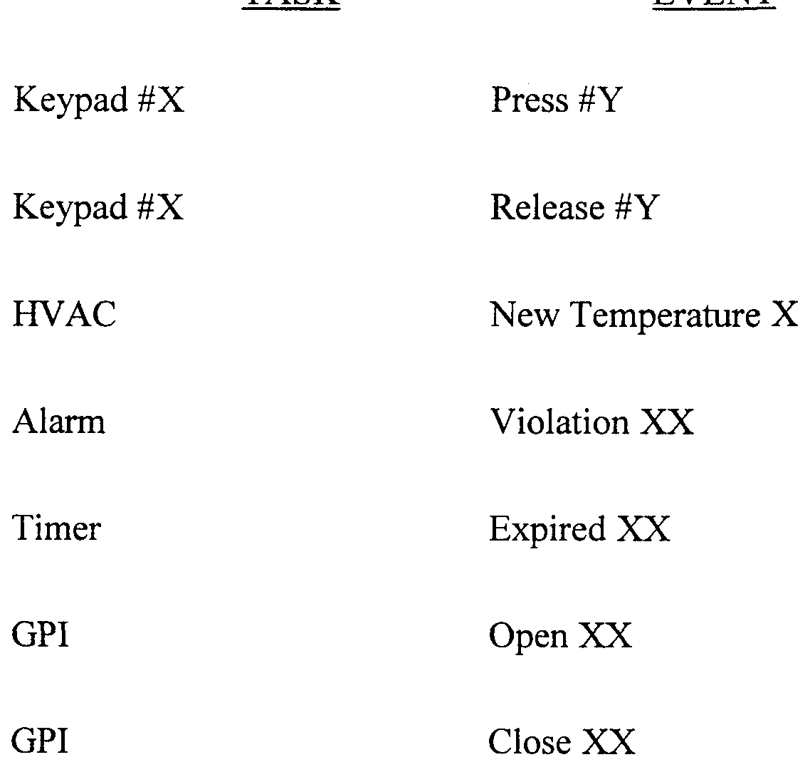
  • buttons number may have one set of commands for the pressing of a button number Y on a
  • keypad number X may have an entirely separate set of commands for the
  • control database unit 44 may also have separate sets of commands for the sensing
  • task units such as task units 54, download task unit 52, and
  • keypad control task unit 46 store values for their own local variables and use these
  • the lighting task unit 54E may need to be used by the lighting task unit 54E when determining whether to
  • variable database unit 48 is a vehicle by which one task unit can access
  • variable database unit 48 The variable database unit 48
  • variable database unit 48 by which a task unit interacts with the variable database unit 48 is shown in Fig. 6.
  • a task unit queries the virtual database unit 48 for the value of a
  • a query may include an identifier for the task that owns the
  • variable a number identifying the variable
  • preferred return format which
  • variable database unit 48 queries the task unit
  • variable database unit 48 returns the
  • variable database unit 48 also provides updates to all interested task
  • variable database unit 48 notifies the variable database unit 48 at step 112 of a change in
  • step 114 the variable database unit 48
  • variable database 48 notifies other tasks of the new value for the variable.
  • a shared variable preferably constitutes an input/output event that triggers the
  • control database unit 44 to initiate a set of commands for updating all interested
  • variable database unit 48 may store the value of some shared
  • variables such as the current time, the current date, or other such system
  • a shared variable may be an ambient room temperature.
  • the HVAC task unit 54C is the owner's task for the ambient temperature and
  • the HVAC task 54C as described above with reference
  • variable database unit 48 in turn, also notifies all interested tasks of the new value
  • control database unit 44 One of these interested
  • tasks may be keypad control task unit 46 which displays the current temperature
  • variable database unit 48 the programming of the control system 10 is greatly
  • the software 14 is not characterized by numerous lines of codes but
  • code for the software 14 is fairly small and can be easily debugged. Rather than
  • the programmer can then operate the system 10 based on the
  • the programmer can "open" the door in software and follow the
  • control system 10 is not limited to any particular arrangement of
  • control system 10 may be designed to have a wide variety of functionality,
  • control over audio/video sources Due to the flexibility in the design of the control
  • control system 10 can be used within a diverse range of commercial
  • control system 10 may form a part of is
  • the central processor 12 may be connected through a first
  • network interface 24A to a plurality of network devices 122. These devices may
  • an audio keypad 122C an audio keypad 122C
  • a static keypad 122D an audio matrix 122E, or a
  • thermostat 122M The MagicPad interface 122 A, the MagicBook graphical user
  • the audio matrix 122E is also available from the assignee of the
  • present invention and provides source selection, volume control, bass control, and
  • the audio matrix 122E also provides six
  • contact sensors for monitoring the power status of attached sources and an output
  • the network interfaces 24 need not
  • thermostat 122M as a thermostat 122M.
  • control system 10 can be connected to more than one
  • network interface 24 in order to expand the number of devices 122 that may be
  • interface 24A may be connected to plurality of other network interfaces 24 to form
  • network is preferably an - 29 -
  • the network may comprise another type of communication
  • the network may comprise an RS 485 network
  • the network may have an RS 232 adapter as one of the network devices 122.
  • the network may have an RS 232 adapter as one of the network devices 122.
  • interface 24A may also be used to connect to another control system 10 to further
  • a lighting controller such as
  • LC-16 lighting controller is preferably connected to the CeBUS/LonWorks
  • the central processor 12 preferably includes a second network port for
  • interface 24N+1 may advantageously be used for a thermostat or may be used to
  • control system 10 to use any Ademco security panel for a large or complex
  • the relays 38 in Fig. 1 are just an example of a device that may be
  • control system 10 can conveniently control power to other devices and thus
  • the relays 38 may comprise circuit
  • breakers such as low voltage controlled circuit breakers, for controlling a plurality - 30 -
  • devices 132 including a water heater 132A, a sump pump 132B, a pool pump
  • an access control device 132D an access control device 132D, a gate opener 132E, or a CD player 132M.
  • circuit breakers 38 may be used as an alternate means of controlling
  • power to the stereo or may be used to control auxiliary audio or video components.
  • the operating system 16 can selectively control any one of the relays 38 in
  • system 10 may have any number of relays, but preferably includes at least twelve
  • whistles, or other devices may be controlled by the system 10 through the relays
  • processor 12 may be optimally set according to the desires of a particular
  • control system 10 As an example, as shown in Fig. 10, the
  • central processor 12 may be connected to a panic sensor 34 A, a flood sensor 34B,
  • a daylight sensor 34C a driveway sensor 34D, a meter pulse from an electrical
  • the central processor 12 may be
  • the hardware 42 which may trigger an input event as shown in step 60 in Fig. 3. - 31 -
  • the control system 10 may form a plurality of alarm zones from zone
  • zone 40A to zone 40N, but preferably includes at least six alarm zones 40.
  • Each alarm is preferably included in zone 40N, but preferably includes at least six alarm zones 40.
  • zone such as alarm zone 40A
  • alarm zone 40A is connected to a plurality of alarm sensors 152.
  • the sensors 152 may include a door sensor 152A, a window sensor 152B, an ultra
  • sonic detector 152C an infrared detector 152D, a magnetic contact 152E, or any combination thereof
  • the sensors may be any type of mechanical switch 152M.
  • the sensors may be any type of mechanical switch 152M.
  • the sensors may be any type of mechanical switch 152M.
  • the sensors may be any type of mechanical switch 152M.
  • the sensors may be any type of mechanical switch 152M.
  • the sensors may be any type of mechanical switch 152M.
  • the sensors may be any type of mechanical switch 152M.
  • the sensors may be any type of mechanical switch 152M.
  • interface 24 may be used as an Ademco interface to further expand the security
  • commands can be classified as either a core command related to
  • core units are always present on a control system 10 and include the core units of
  • units 54 in contrast, can include any one or any combination of the task units 54
  • the control system 10 has a
  • unit 48 may need to be changed to include additional sets of commands or to
  • a keypad event at 160 such as the
  • control task unit 46 queries the control database unit 44 for the appropriate
  • the query includes a task identifier identifying the keypad control
  • the task unit 46 and also an identifier for the event.
  • the event identifies the address of
  • each keypad has a finite number of
  • each keypad can have an infinite number of virtual keys in software by using
  • control database unit 44 looks up the set
  • step 164 the command execution unit 50 sends the
  • control task unit 46 queries the variable database 48, if necessary, to obtain values
  • the commands may vary according to the particular keypad and hardware, but - 33 -
  • the download task 52 can advantageously be used to download upgrades or
  • the interconnect event may be a
  • download task unit 52 at step 172, then queries the control database unit 44 for the
  • database unit 44 passes a pointer to the set of commands to the command
  • execution unit 50 which then routes the set of commands to the appropriate task
  • step 175 the download
  • task unit 52 queries the variable database unit 48 for values of any shared variables
  • step 176 uses the operating system 16 and the system resources to
  • the task units 54 are configured according to the desired features in the control system 10, the task units 54
  • step 180 the task - 34 -
  • the task unit With a change in any local variable, the task unit also updates the variable
  • the task unit 54 can be programmed according to the particular desires of
  • the task units may interact with the overall control system 10 and with devices
  • the multi-room audio task unit 54 responds to the commands
  • Set_Bass which sets the volume level of the
  • Set_Treble which sets the treble volume for a particular zone
  • the multi-room audio task unit 54A also maintains shared
  • the general purpose interface task unit 54D is used to control the relays 38
  • interface task unit 54D responds to the commands of Activate_Relay to activate a
  • Pulse_Relay to pulse a relay at a
  • Update_Var to return the updated value of a variable to the variable database unit
  • the general purpose interface task unit 54D also maintains the shared
  • purpose interface task unit 54D will simply be monitoring a device's status and
  • control system 10 can be programmed so that a
  • control system 10 allows this easy interaction between task
  • HVAC task 54C At step 191, a security event is detected with the hardware 42
  • the security event can be any one of any number of events, such as a change
  • MagicBook 122B or static keypad 122D to arm or disarm the security system.
  • security task unit 54B queries the control database unit 44 for the set of commands - 36 -
  • control database unit 44 provides the
  • command execution unit 50 with a pointer to the set of commands at step 194.
  • the command execution unit 50 routes the commands to the appropriate task units
  • unit 50 provides commands to both the security task unit 54B and the HVAC task
  • the HVAC task unit 54C may be structured
  • the general purpose interface task unit 54D may also receive
  • the lighting task unit 54E may also receive a command from the
  • command execution unit 50 to turn off the lights throughout the entire house or
  • unit 54A may also receive a command from the command execution unit 50 to
  • the HVAC unit, hot water heater, lighting, and audio video in the house may only be the HVAC unit, hot water heater, lighting, and audio video in the house.
  • a condition may be placed on the commands sent to the task units other - 37 -
  • the task units may receive the commands only if the
  • the control system 10 therefore allows one to force the actual consumption
  • hot water heater 152A the lighting, and all the audio and video devices within the
  • the house may be turned off when the occupant is not within the premises. In all, the
  • control system 10 enables an occupant to have more control over the consumption
  • the control system 10 may also include the energy management task unit
  • task unit 54F permits an occupant to respond in real-time to fluctuations in pricing
  • control system 10 can be any type of electricity .
  • the control system 10 can be any type of electricity .
  • the control system 10 can be any type of electricity .
  • the control system 10 can be any type of electricity .
  • the control system 10 can hook up to the utility
  • control system 10 may initiate a dial-up access through the telephone
  • the control system 10 may also receive the rate information in
  • the operating system 16 wakes up the energy task unit 54F at step
  • step 206 the energy task unit 54F and the other affected task units 54
  • the energy task unit 54F at this step, can provide
  • variable database unit 48 provide these updated values to the variable database unit 48.
  • database unit 48 in turn, provides updates to all other task units 54 that share the
  • the energy task unit 54F for instance,
  • updating of the set points may be an input/output event that has a set of commands
  • the HVAC task unit 54C may be one of the task units that
  • task unit 54E may also be affected by changes in the pricing of electricity. - 39 -
  • management task unit 54F may also be used to provide a greater degree of
  • the utility company may
  • energy task unit 54F can respond by comparing the amount in the bill with an
  • task unit 54F can be displayed by the keypad control task unit 54 46 on a keypad
  • the occupant can review the bill and can initiate an
  • the energy task unit 54F may receive a
  • the energy management task unit 54F may also be used in Automated
  • AMR Meter Reading
  • management task unit 54F permits a great degree of control over the consumption
  • control database unit 44 has been described as storing a set of
  • task unit that is woken up in response to an event may not receive any of the
  • woken-up task unit receives from the command execution unit 50 includes the null

Abstract

A control system (10) is extremely flexible and modular and can be equipped or upgraded to have any number or combination of features, such as security, home theatre/audio (54A), HVAC (54C), energy management (54F), and lighting (54E) with each feature having a separate task unit. The task units can be added or removed from a core set of units within minimal impact on the core set of units. The core set of units includes a control database unit (44) that stores sets of commands in a relational database according to an input/output event and a command execution unit (50) that routes the commands to the appropriate task units for execution. The core set of units do not need to understand the input/output event or the commands but rather routes the commands to the task units addressed for execution. The system has a variable database (48) that contains a relational database of variables shared between the various task units and stores such things as keypad displays. The individual task units query the variable database unit (48) for values of all share variables and automatically receive any update in values of the shared variables from the variable database unit (48). The software (14) for the system is stored in flash ROM and can be automatically upgraded through a download task unit (52). The system may have an energy task unit (54F) that adjusts consumption of electricity based on any change in rate and which provides a pathway of communication with the electrical utility company.

Description

- 1 -
SYSTEM AND METHOD FOR PROVIDING MODULAR
CONTROL AND FOR MANAGING ENERGY CONSUMPTION
NOTICE OF COPYRIGHTED MATERIAL IN DISCLOSURE
A portion of the disclosure of this patent document contains material that is
subject to copyright protection. The copyright owner has no objection to the
facsimile reproduction by anyone of the patent document or of the patent
disclosure, as it appears in the Patent and Trademark Office patent file or records,
but otherwise reserves all copyright rights whatsoever.
CROSS-REFERENCE TO RELATED APPLICATIONS
Reference is made to co-pending Patent Cooperation Treaty application
entitled "USER INTERFACE FOR HOME AUTOMATION SYSTEM," having
International Application No. PCT/US96/14520 and International Filing date of
September 18, 1996.
FIELD OF THE INVENTION
In one aspect, the invention generally relates to a system and method that
provides modular control over various tasks, such as security, home theatre, audio,
HVAC, and lighting. In another aspect, the invention generally relates to a system
and method for managing energy consumption and, more particularly, for
permitting adjustments to energy consumption based on changing conditions. - 2 -
BACKGROUND OF THE INVENTION
A residential security system, typically, is a stand-alone system that
monitors various alarm conditions, such as the opening of a door or window or
motion in a room. In response to these conditions, the security system may initiate
an alarm and may auto-dial the police or a monitoring company. In many
residences, the security system is equipped with several keypads with one often
located near a main entrance and another located in the master bedroom. Although
the exact design of keypads vary greatly, many keypads have numeric keys for the
entry of special codes to disarm the system, indicators for displaying zone
violations, and dedicated keys for auto-dialing the police or fire department. With
this type of security system, a processing unit, which may be placed in a closet or
other hidden area, is interconnected to the various motion sensors, closure
contacts, the keypads, a siren, and includes the auto-dialer.
The typical residential security systems is a stand-alone device and has no
interaction with other devices or systems in a residence. For instance, the typical
security system is not interconnected and in no way controls a stereo system or a
home theatre system. The security system also has no control over a heating,
ventilating, and air conditioning (HVAC) unit and normally does have control over
the lighting within the residence. These other devices or systems in the residence,
instead, are stand-alone systems that provide dedicated control over the devices
within their domain. For instance, an audio system may selectively control the - 3 -
routing of sound from a centralized audio source to numerous areas within or near
the residence and may have separate keypads for each area of the residence. The
home theatre system may similarly have keypads throughout the house for
selectively supplying video from a central source to the various areas in the
residence.
As a result of these independent systems, a residence may have a multitude
of keypads distributed throughout the house. A single room, or even a single wall,
may have several keypads which can be quite unsightly and detract from the
overall appearance and decor of the residence. The keypads can also be quite
troublesome to a resident since the keypads for the different systems in the
residence are often associated with a particular operating methodology unique for
each system. As a result, the resident would need to learn one procedure for
operating the security system, another procedure for controlling the audio system,
and yet another for the video system.
In light of a desire to have more automated control over the various devices
in a residence, home automation systems have been developed which integrate the
security system with one or more of the other systems, such as the lighting system.
The home automation systems can provide more integrated control over all
features of a house. With the home automation systems, it could be possible to
perform such functions as turning on the lights in a room upon detection of motion
or activating a coffee maker according to a set schedule. . 4 .
A common approach to designing the home automation systems is to have
a central processor communicate with each of the sub-systems and to coordinate
each of the sub-systems activities. Each of the sub-systems, such as security and
audio, would essentially retain their own internal design and would still have a
processor which can be programmed according to the desires of the resident. To
communicate with each of the sub-systems and to coordinate activities between the
sub-systems, the central processor must know the commands for all of the sub¬
systems. With this knowledge of the commands, the central processor can
command the lighting system to turn on the lights if the security system senses
motion in a room or perform other coordinated functions between the sub-systems.
To address the problems with multiple keypads, home automation systems
have merged two or more keypads for more than one sub-system into a single
"smart" keypad. By reducing the number of keypads, the resident can more easily
learn the methodology for operating the keypads and the residence would have less
wall space consumed by the keypads. These smart keypads are programmed to be
able to send various commands to the central processor which can then route
theses commands to the individual sub-systems. To store and transmit these
commands, a smart keypad has a processor and memory with the memory
preferably being fairly large so that the keypad is able to store and convey a
greater number of commands to the central processor.
The typical home automation system, therefore, is characterized as being a
fairly powerful system with processors and associated memory in the central - 5 -
processor, in each of the sub-systems, and in the keypads. Because of the amount
of electronics throughout the system, home automation systems have consequently
been typically rather expensive. A need therefore exists for a home automation
system that is not only less expensive but which does not sacrifice performance.
The typical home automation system is also rather difficult to design and
develop. As discussed above, the sub-systems, the central processor, and the
keypads all have processors and each of the processors are associated with some
type of software program. The programs in each of the processors must be
written, complied, and debugged. The initial writing of the programs is fairly
difficult just considering the lines of code that must be generated for all of the
processors. The task of generating the code, however, does not end with simply
writing the code since the code must next be compiled, with is often laced with
various syntax errors if the code does not include the proper spacing, positioning
of commas, semi-colons, brackets, or other such punctuation or grammar. Once
the programmer successfully compiles the code, the programmer is next faced with
the onerous job of debugging the code. The programmer is inevitably challenged
with having to detect problems area in the code, rewriting the code, and then
repeating the steps of compiling and debugging. A significant portion of the
design and development of the home automation system is therefore devoted to the
process of writing, compiling, and debugging the code.
The difficulties with the code do not stop once the home automation system
has been installed but continue if the resident desires another modification or - 6 -
upgrade. For instance, if the resident would like an additional keypad, the home
automation system must be reprogrammed to know the address of the keypad.
Furthermore, if the system only included security and audio and the resident wants
an upgrade to include lighting, the home automation system must undergo some
additional programming to accommodate the additional sub-system. This
additional programming involves the writing, compiling, and debugging the code,
and therefore serves as an obstacle to any modification or upgrade to the home
automation system. As such, a need exists for a home automation system that can
more easily and readily accommodate changes.
While an ideal home automation system includes all possible features,
home automation systems practically are not all-inclusive. First of all, a home
automation system which included all possible features would undoubtedly have
an exorbitant cost. Consumers of home automation systems are not unanimous in
the features that they desire and, as a result, home automation systems are
designed to have various combinations of features. In addition to the economics,
rapid changes in technology preclude such an all-inclusive system. As technology
advances and becomes available, home automation systems will be encouraged to
incorporate the new technology.
Other forces at work in technology and in the marketplace create new
opportunities not only for home automation systems but for any residential control
system. These forces include the increased competition between companies
providing local phone service, long distance phone service, cellular phone, pager - 7 -
service, cable television, and Internet access. The lines between companies that
traditionally provided only one or two of these services are fading as the laws and
regulations are being rewritten to encourage the competition between companies.
A residential control system, such as a home automation system, should therefore
be flexible to accommodate and incorporate the changes that are imminent with
the provision of telephone, cable, and Internet services.
In addition to the deregulation of the communications field, deregulation
and increased competition with electrical utility companies will also likely have an
impact on the provision of services in the field of electrical power. A utility
company as well as all other generators of electricity generally implement a tiered
approach for meeting the demand from all of its customers. At the first step,
demand from all of its customers for electricity is relatively low and can be
satisfied by the utility company's most energy efficient generators. As the demand
becomes high and increases past the capacity of these higher efficiency generators,
the utility company relies on less efficient and more expensive generators. These
more expensive generators are less desirable due to their relatively low efficiency,
their use of more expensive fuels, their higher levels of pollution, or the fines
which are associated with their operation. At the third step, after the demand
exceeds the internal capacity of a utility company, the utility company then
purchases electricity from other utilities, often at a premium.
The utility companies, however, have very little control over the demand
for electricity and thus limited control over their costs. Presently, an individual - 8 -
consumer of electricity, such as a household, has no knowledge of the demand
level of the utility company unless the demand becomes an emergency issue for an
entire geographical region. Thus, unless some type of warning has issued,
consumers use as much electricity as they desire and at the times that they desire.
A need therefore exists for a system or method by which utility companies can
inform consumers of the present demand so the consumers can act to reduce the
overall demand and thus act to reduce the overall cost of electricity.
Even if consumers had knowledge of the particular demand level for a
utility company, however, the consumers would have no immediate incentive to
alter their use of electricity to help keep the overall demand at a low level. While
the aggregate effect of each individual consumer's activity could help keep costs
down and thus lower the overall cost of electricity, a single consumer would have
little incentive to alter his or her usage merely to increase the profits of the utility
company. Further, although costs to the consumers may likely be reduced if the
overall demand on a utility company is lower, many consumers may be unwilling
to alter their schedules to less convenient times when other consumers, who do not
alter their schedule, still receive the benefits of the reduced costs. A need thus
exists for a system or method which provides incentives for consumers to reduce
the overall demand on the utility company and which provides consumers with
direct and prompt benefits.
In addition to the high cost associated with purchasing electricity from
another utility company, the purchase of electricity from another utility company - 9 -
has other drawbacks. For instance, the chance and impact of a power failure
increases with the number of utility companies in a power grid. As evident by
events in the Pacific Northwest, an isolated and relatively minor failure can cause
power outages in an area spanning several states. Thus, a need exists for a system
or method for controlling overall demand on electricity, not only because a lower
demand would reduce costs, but also because a lower demand would reduce the
reliance on integrated power grids and should therefore increase the overall
reliability of the utility companies.
Another problem facing a utility company is that it has a fairly small
capacity to communicate with its consumers. Under typical circumstances, this
contact is limited to a monthly bill detailing the total amount of electricity
consumed and the associated cost. The utility company therefore staffs a relatively
small number of personnel to handle consumer problems. During a power failure,
on the other hand, a massive number of consumers call in to inquire as to the
problem. At these times, the utility company is ill-equipped to handle all of the
calls and consumers may be placed on hold for an extremely long period of time,
such as an hour or more. This inattentiveness to the consumers' calls can
significantly magnify the consumers' aggravation toward the situation and to the
utility company. A need therefore exists for a system or method which improves
communications between consumers and a utility company.
A need also exists for a system or method by which consumers can have an
increased amount of control over their energy usage. Typically, each appliance - 10 -
within a house has its own dedicated control. For instance, a heating, ventilating,
and air conditioning (HVAC) unit within a house has a thermostat for setting the
desired temperature and a hot water heater has a control unit for controlling the
temperature of the water. Additionally, the stereo, television, computer, and lamps
would each have separate on/off switches. To reduce energy consumption, the
consumer would therefore have to individually control each separate appliance,
which can be quite burdensome. It is therefore a desire to have greater and easier
control over energy consumption.
To partially fulfill the desire for greater control over energy consumption,
certain appliances have been equipped with programmable units. For instance,
many HVAC units have programmable control units which allows the consumer to
indicate different desired temperatures for different times of the day and for
different days of the week. These controls provide the consumer with the ability
to match consumption more closely with the actual need. Once these control units
have been programmed, however, the consumer must reprogram the unit so that
the programmed schedule of usage becomes equal to the actual desired schedule of
energy usage. For example, if a person comes home earlier than normal, the
person must manually adjust the setting on the HVAC to the desired setting. Since
a person's schedule can change often, a need exists for a system or method of
controlling energy consumption which can adjust more easily and quickly to a
desired or actual schedule of usage. - 11 -
SUMMARY OF THE INVENTION
It is an object of the present invention to provide a control system which
can be easily programmed with a desired combination of features.
It is another object of the present invention to provide a control system
which can easily be changed to accommodate an additional feature or function.
It is still another object of the present invention to provide a control system
which has a more streamlined design in terms of processors and programming.
It is yet another object of the present invention to provide a control system
which is less expensive yet has no sacrifice in performance.
It is a further object of the present invention to provide a control system
which provides keypads or other input/output units which provide a high number
of keys with a minimal amount of hardware.
It is another object of the present invention to provide a system which
permits a greater amount of control over the consumption of electricity.
It is yet another object of the present invention to provide a system which
permits a greater amount of control over the overall cost of electricity to a
customer.
It is another object of the present invention to provide a system which
provides a greater amount of communication between a provider of electricity and
its customers.
Additional objects, advantages and novel features of the invention will be
set forth in the description which follows, and will become apparent to those - 12 -
skilled in the art upon reading this description or practicing the invention. The
objects and advantages of the invention may be realized and attained by the
appended claims.
To achieve the foregoing and other objects, in accordance with the present
invention, as embodied and broadly described herein, a control system and method
according to the invention have one or more task units and a set of core units.
Each of the task units is for overseeing at least one device and may include a
multi-room/home theatre task unit, security task unit, heating, ventilating, and air
conditioning task unit, general purpose interface task unit, lighting task unit, or
energy management task unit. A central processor is coupled to the devices
managed by the task units and includes a control database unit for storing sets of
commands in a relational database according to event and a command execution
unit for routing the commands to their respective task units. A monitoring unit,
which preferably comprises a multi-tasking preemptive operating system for the
processor, receives input/output events from the device or task units and wakes up
the individual task units associated with the events. The task units, in response,
query the control database unit for the set of commands associated with the event
and the control database unit identifies the set of commands to the command
execution unit. The command execution unit routes the commands to the task
units addressed within the commands and the task units, after receiving the
commands, process the commands. - 13 -
The control system and method are extremely flexible and modular
whereby task units can be added or replaced with only a minimal impact on the
overall system. By storing the sets of a commands in a relational database, the
control database and the command execution unit need not understand the
commands or the events but rather simply route the commands to their respective
task units. The command execution unit need not automatically route the
commands but can instead route the commands only upon the meeting of certain
conditions.
With the preferred system and method, a keypad control unit monitors all
keypad events. The keypads need not contain a large amount processing power
since they only need to specify an address for the keypad and a key which was
pressed. The control database unit, based on this identifying data, passes an
appropriate set of commands to the keypad control unit and to any other affected
task unit. The control system and method reduce the amount of processing that
must occur at the keypads and between task units and consequently reduce the
complexity and cost of the system.
The system and method may advantageously be used to monitor and
control energy consumption of at electrical load. The system may have an energy
management task unit that receives rate information, such as from the provider of
electricity, and can adjust consumption accordingly. For instance, the load may
comprise an HVAC unit and the energy management task unit may alter
temperature set points of the HVAC based on the rate information. Thus, when - 14 -
the demand for electricity and the rate both increase, the system and method can
act to reduce consumption and to lower the cost of electricity. Conversely, when
the rate decreases, the system and method can take advantage of the lower rates by
adjusting the set points to a more comfortable level.
The system and method preferably include a variable database unit and a
download task unit. The variable database unit maintains a relational database of
the values of variables which are shared between task units. The task units can
query the variable database unit for values of any shared variable and also can
receive automatic updates on the values of shared variables. The download task
unit can respond to a download request by storing software program or data
received from an external source into non- volatile memory. The download task
can conveniently be used to upgrade existing software or data in memory or to
modify the system or method to include new software or data.
BRIEF DESCRIPTION OF THE DRAWINGS
Fig. 1 is a block diagram of a control system according to a preferred
embodiment of the invention;
Fig. 2 is a block diagram of the control system of Fig. 1 illustrating the
processor and software in further detail;
Fig. 3 is a flow chart illustrating an overall process by which the control
system of Fig. 1 processes an input/output event; - 15 -
Fig. 4 is a flow chart illustrating operations of a command execution unit
shown in Fig. 2;
Fig. 5 is a flow chart illustrating a processing of core commands in the
control system of Fig. 1 ;
Fig. 6 is a flow chart illustrating a process of querying a variable database
unit shown in Fig. 2;
Fig. 7 is a flow chart illustrating a process of updating task units with new
values of shared variables;
Fig. 8 is a partial block diagram of the system of Fig. 1 interconnected with
an exemplary network;
Fig. 9 is a partial block diagram of the system of Fig. 1 interconnected to an
exemplary set of relays and devices;
Fig. 10 is a partial block diagram of the system of Fig. 1 interconnected to
an exemplary set of sensors;
Fig. 11 is a partial block diagram of the system of Fig. 1 interconnected to
an exemplary set of security devices;
Fig. 12 is a flow chart illustrating a processing of a keypad event;
Fig. 13 is a flow chart illustrating a download process executed by the
control system of Fig. 1;
Fig. 14 is a flow chart illustrating a general process of activity within a task
unit within the control system of Fig. 1 ; - 16 -
Fig. 15 is a flow chart illustrating an exemplary process by the control
system of Fig. 1 in which security functions are interrelated to HVAC events; and
Fig. 16 is a flow chart illustrating an exemplary process by the control
system of Fig. 1 in which energy consumption can be adjusted based on rate
information from a utility company.
DETAILED DESCRIPTION
With reference to Fig. 1, a control system 10 according to a preferred
embodiment of the invention comprises a central processor 12 which is preferably
a multi-tasking processor. The central processor 12 is loaded with software 14,
which includes an operating system (OS) 16 and application programs 18.
Preferably, the central processor 12 is the Motorola 68000 preemptive multi¬
tasking processor and the operating system 16 is Omega DOS, although other
multi-tasking operating systems can be used. The central processor 12 is
connected to non- volatile memory 20, or flash ROM 20, which preferably stores
the software 14. A power supply 22 supplies power to the central processor 12 as
well as to the rest of the system 10 and preferably includes a battery backup power
supply.
The control system 10 includes a number of interfaces, which may include
a network interface 24, a consumer electronic bus (CeBUSVLon Works bus
interface 26, and a telephone interface 28. The network interface 24 preferably
comprises a multi-drop network and, more precisely an RS 485 network and the - 17 -
telephone interface 28 is connected to a central office line and also to an internal
telephone line. The control system 10 may also be equipped with a pager receiver
30 and an infrared transmitter 32. The control system 10 is extremely flexible in
the manner in which it can communicate with external devices or systems in that it
can communicate over conventional telephone lines with telephone interface 28,
can receive wireless communications from pager receiver 30, can transmit infrared
communications with infra-red transmitter 32, and can communicate in various
standards or protocols, such as RS 485, the CeBUS standard, and the Lon Works
standard. The control system 10 is not limited to these methods of communication
but may incorporate other methods of communication, such as with other
communication standards or protocols or with other communication transceivers
or mediums, such as optical fibers.
The control system 10 has a plurality of input ports for receiving signals
from devices within the system 10 and output ports for supplying signals to
devices within the system 10. The input ports include those connected to sensors
34 and alarm zones 40 and the output ports include those connected to a siren 36
and to relays 38. The sensors 34, as will be described in more detail below, can be
any type of sensor and may provide information related to security, energy
management, lighting, or other features of the control system 10. The alarm zones
40 may represent security sensors grouped according to their type, such as door
sensors, or grouped according to their proximity, such as according to the rooms in
a building. - 18 -
A more detailed diagram of the control system 10 showing components of
the software 14 and particularly the application programs 18 is shown in Fig. 2. .
The operating system 16 links the application programs 18 to the other
components of the control system 10, which have been generally indicated as
hardware 42. The application programs 18 may include a number of task units 54,
each of which includes a stand-alone program, a stack, and private memory
storage. The exact number and functions of the task units 54 may vary according
to a desired design of a control system 10, but may include such things as a multi-
room audio/home theater task unit 54 A, a security task unit 54B, a heating,
ventilating, and air-conditioning task (HVAC) unit 54C, a general purpose
interface task unit 54D, a lighting task unit 54E, and an energy management task
unit 54F. A significant advantage of the invention is that additional task units can
be easily added to the control system 10.
The application programs 18 include a number of core units which are
preferably common to any control system 10 regardless of the exact selection of
task units 54. The core units include a download task unit 52 and a keypad control
task unit 46. The download task unit 52 is used to download data from an external
source to the flash ROM 20 and is beneficial when upgrading the software 14 in
the system 10 or when adding new software to the system 10. The keypad control
task unit 46 is used to control keypads associated with the control system 10 and
consequently controls any displays or indicators on the keypads. The core units in
the system 10 further include a control database unit 44, a variable database unit - 19 -
48, and a command execution unit 50. In general, the control database unit 44
stores commands which are executed by the various task units in the control
system 10 and the variable database 48 maintains the most recent values of any
variables shared between the task units. The command execution unit 50 receives
the commands from the control database unit 44 and routes the commands to the
proper task units for execution.
An overall process by which the control system 10 operates is shown in
Fig. 3. In response to an input/output event occurring at step 60, the operating
system 16 wakes up the particular task unit assigned to that event at step 61 by
sending that event a notice signal. The input/output event may be one of any of a
plurality of events, including such things as the pressing, releasing, or holding
down of a button on a keypad, an alarm state change detected in one of the zones
40, or an HVAC system state change as detected with one of the sensors 34. The
input/output event may also be caused by a device or system external to the system
10, such as a communication through telephone interface 24, network interface 24,
CeBUS/Lon Works interface 26, or pager receiver 30. Furthermore, the
input/output event includes activity from another task unit. For instance, an
operation by the HVAC task unit 54C of activating a relay 38 may be considered
an input/output event that triggers a response from the keypad control task unit 46
to alter a display on one of the keypads.
At step 61, the operating system 16 wakes up the task units assigned to that
input/output event, such as any of task units 46, 52, or 54. The operating system - 20 -
16 detects the task responsible for an event based on an address portion of the
signal which is generated with the event. The operating system 16 thus reads this
portion of the signal and supplies a notice signal to the addressed task unit. At step
62, the woken-up task unit queries the control database unit 44 for commands
associated with the input/output event. The control database unit 44 maintains a
relational database of all input/output events and the sets of commands associated
with each input/output event. At step 63, the control database unit 44 looks up the
set of commands associated with the received input/output event and supplies a
command pointer to the command execution unit 50. The command pointer
identifies that portion of the relational database where the set of commands for the
input/output event are stored. At step 64, the command execution unit 50 sends
the commands to the appropriate task unit or task units. As with the operating
system 16, the command execution unit 50 does not determine the type of
command but rather routes each command based on an address portion stored in
the relational database. After the commands are passed to their respective task
units, the task units rely on the operating system 16 and other resources of the
system 10 in order to execute or otherwise process the command. The operating
system 16 provides all of the necessary device drivers, such as those for timers,
serial communications, network communications, IR transmissions, XI 0
communications, dual-tone multi-frequency (DTMF) communications, and for the
relays 38. - 21 -
An operation of the command execution unit 50 is shown in more detail in
Fig. 4. At step 70, a task unit which has been woken-up queries the control
database unit 44 for the set of commands and the control database unit 44 supplies
the command execution unit 50 with a command pointer to the set of commands
associated with the input/output event. At step 72, the command execution unit 50
turns to the first command in the set and determines whether the command has a
condition associated with it. If the command does have a condition associated
with it, the command execution unit 50 next determines at step 74 if the condition
has been satisfied. The condition may be a certain value of a variable, the state of
a variable, or any other type of condition which must be satisfied before the
command will be executed. As an example, when a door is opened to a room as
detected within one of the alarm zones 40, a command associated with this
input/output event may be the turning on of a light in that room. Since the light
should preferably remain off during the day, a condition may be attached to this
command which will cause the command to be executed only when the door is
opened during night-time hours, which may be detected with a daylight sensor
within sensors 34 or simply with a time-of-day clock.
If the condition has not been met, then at step 82 the command execution
unit 50 turns to the next command in the set of commands. If the condition has
been met or if the command is not conditional, as determined at step 72, then the
command execution unit 50 next determines whether the command is a local
command at step 76. A local command is a command that may be executed by the - 22 -
command execution unit 50 itself and need not be supplied to a task unit. The
local commands may include a DO MACRO command for branching execution to
a macro command sequence, a LINK command for linking other task units or
events, a DELAY command for initiating a delay in processing, or a CANCEL
DELAY which cancels a pending delay. The command execution unit 50 may be
structured to have other local commands if desired. If the command is a local
command, the command execution unit 50 will consequently execute the
command itself.
If the command is not a local command as determined at step 76, then the
command execution unit 50 will forward the command to the appropriate task unit
at step 80. The control database unit 44 stores the sets of commands according to
task unit. As a result, the command execution unit 50 need not make an
independent assessment of the type of command but rather simply looks at that
portion of the command which addresses the designated task unit for that
command. Based on this portion of the command, the command execution unit 50
routes the command to the appropriate task. At step 82, the command execution
unit 50 then turns to the next command.
Fig. 5 summarizes the processing of commands by the task units. At step
90, the control database unit 44 provides a command pointer to the command
execution unit 50. At step 92, the command execution unit 50 sends the command
to the task unit that was addressed by the command and the task unit executes the
task at step 94. The command that is executed by the task unit need not result in - 23 -
the generation of any output signal but rather may result in some internal
processing, such as updating the value of a variable. The task units may rely upon
the operating system 16 in the execution of the commands.
More specifically, the control database unit 44 stores the sets of commands
in the non- volatile flash memory 20. A query to the control database unit 44
includes a task identifier and an event number. The control database unit 44, in
turn, supplies a resulting command pointer to a first command in the set addressed
by that task identifier and event number. By storing the sets of commands in a
relational database, the control database unit 44 need not determine what type of
action should result from a given input/output event but can instead simply point
the command execution unit to the set of commands associated with the
input/output event. As shown below in Table 1, the task identifier and event
number may have one set of commands for the pressing of a button number Y on a
keypad number X and may have an entirely separate set of commands for the
release of button number Y on keypad number X. The relational database in
control database unit 44 may also have separate sets of commands for the sensing
of a new temperature in the HVAC, an alarm violation, an expired timer, an open
contact, or a closed contact. 24
TASK EVENT
Keypad #X Press #Y
Keypad #X Release #Y
HVAC New Temperature X
Alarm Violation XX
Timer Expired XX
GPI Open XX
Figure imgf000026_0001
GPI Close XX
Table 1
Most of the task units, such as task units 54, download task unit 52, and
keypad control task unit 46, store values for their own local variables and use these
values as needed. Some of these variables, however, may be needed by one or
more of the other task units in the execution of their commands and therefore must
be accessed by these other task units. For example, the state of a daylight sensor
within sensors 34, which is stored by the General Purpose Interface task unit 54D,
may need to be used by the lighting task unit 54E when determining whether to
turn on a light upon the opening of a door. - 25 -
The variable database unit 48 is a vehicle by which one task unit can access
the value of a variable stored by another task unit. The variable database unit 48
provides a virtual database of variables and any task unit can query the variable
database unit 48 for a value of any variable shared between task units. A process
by which a task unit interacts with the variable database unit 48 is shown in Fig. 6.
At a step 100, a task unit queries the virtual database unit 48 for the value of a
shared variable. A query may include an identifier for the task that owns the
variable, a number identifying the variable, and a preferred return format, which
may be a string variable of variable length or an integer which is preferable a 16
bit signed number. At step 102, the variable database unit 48 queries the task unit
responsible for that variable for the value of the variable and, in response, receives
the value for the variable . At step 104, the variable database unit 48 returns the
value of the requested variable to the task unit in the format specified by that task
unit.
The variable database unit 48 also provides updates to all interested task
units upon the occurrence of any change in the value of a shared variable. With
reference to Fig. 7, at a step 110, when the value of a shared variable changes, the
owner's task unit notifies the variable database unit 48 at step 112 of a change in
the value for that shared variable. Next, at step 114 the variable database unit 48
notifies other tasks of the new value for the variable. The variable database 48
need not notify all of the task units, but rather may send an automatic update to
only those interested task units requesting the automatic updates. The updating of - 26 -
a shared variable preferably constitutes an input/output event that triggers the
control database unit 44 to initiate a set of commands for updating all interested
task units. While the values of the shared variables are preferably stored by the
owner's task, the variable database unit 48 may store the value of some shared
variables, such as the current time, the current date, or other such system
information.
As an example, a shared variable may be an ambient room temperature.
The HVAC task unit 54C is the owner's task for the ambient temperature and
stores this value in its own memory. When a change in the ambient room
temperature occurs, as described above with reference to Fig. 3, the operating
system 16 wakes up the HVAC task 54C and the HVAC 54C eventually receives
the updated temperature. The HVAC task 54C, as described above with reference
to Fig. 7, then notifies the variable database unit 48 of such a change and the
variable database unit 48, in turn, also notifies all interested tasks of the new value
for the ambient air temperature. These commands for notifying the other task
units are stored as a set in the control database unit 44. One of these interested
tasks may be keypad control task unit 46 which displays the current temperature
on one of the keypads.
By using relational databases in both the control database unit 44 and the
variable database unit 48, the programming of the control system 10 is greatly
simplified. The software 14 is not characterized by numerous lines of codes but
rather is based on the data stored in the relational databases. As a result, the actual - 27 -
code for the software 14 is fairly small and can be easily debugged. Rather than
writing, compiling, and debugging code, a process of generating the software 14
may occur by simply changing the data in the relational databases or by placing
new data in the databases. To verify the operation based on the changes in the
relational databases, the programmer can then operate the system 10 based on the
new changes. For instance, to verify the response of the control system 10 to the
opening of a door, the programmer can "open" the door in software and follow the
actions of the control system 10 to ensure the proper operation of the control
system 10. Significantly, the software 14 can be easily modified by simply
changing the data stored in the relational databases.
The control system 10 is not limited to any particular arrangement of
hardware but rather can be custom designed for a particular application. The
control system 10 may be designed to have a wide variety of functionality,
including security, home automation, energy management, lighting control, or
control over audio/video sources. Due to the flexibility in the design of the control
system 10, the control system 10 can be used within a diverse range of commercial
or residential buildings, such as houses, apartments, townhouses, condominiums,
factories, hospitals, hotels, restaurants, or offices, or within other environments.
An example of a network that the control system 10 may form a part of is
shown in Fig. 8. The central processor 12 may be connected through a first
network interface 24A to a plurality of network devices 122. These devices may
include a MagicPad user interface 122 A, a MagicBook graphical user interface - 28 -
122B, an audio keypad 122C, a static keypad 122D, an audio matrix 122E, or a
thermostat 122M. The MagicPad interface 122 A, the MagicBook graphical user
interface 122B, the audio keypad 122C, and the static keypad 122D are preferable
selected from the line of Magic user interfaces available from the assignee of the
present invention, although other keypads and graphical user interfaces may be
used. Further information on a suitable interface may be obtained with reference
to co-pending PCT application entitled "User Interface for Home Automation
System," having International Application Serial No. PCT/US96/14520 and
International filing date September 18, 1996, which is hereby incorporated by
reference. The audio matrix 122E is also available from the assignee of the
present invention and provides source selection, volume control, bass control, and
treble control for six different zones. The audio matrix 122E also provides six
contact sensors for monitoring the power status of attached sources and an output
relay for controlling a non-sensing amplifier. The network interfaces 24 need not
be connected to just keypads but may be connected to other network devices, such
as a thermostat 122M.
Moreover, the control system 10 can be connected to more than one
network interface 24 in order to expand the number of devices 122 that may be
connected to the system 10. As shown in the example in Fig. 8, the network
interface 24A may be connected to plurality of other network interfaces 24 to form
a multi-drop network with each of these other network interfaces 24 having one or
more network devices 122 connected to them. While the network is preferably an - 29 -
RS 485 network, the network may comprise another type of communication
standard, such as RS 232. Further, the network may comprise an RS 485 network
and may have an RS 232 adapter as one of the network devices 122. The network
interface 24A may also be used to connect to another control system 10 to further
expand the capabilities of the system 10. Additionally, a lighting controller, such
as the LC-16 lighting controller, is preferably connected to the CeBUS/LonWorks
interface 26.
The central processor 12 preferably includes a second network port for
connecting to a network interface 24N+1 with this other network interface 24N+1
having the same capabilities as network interface 24 A. This other network
interface 24N+1 may advantageously be used for a thermostat or may be used to
emulate an Ademco security interface. The Ademco interface would allow the
control system 10 to use any Ademco security panel for a large or complex
security system and would allow the control system 10 to use Ademco peripherals,
such as relays, zone expanders or keypads.
The relays 38 in Fig. 1 are just an example of a device that may be
connected to the output ports of the processor 12. By controlling a set of relays
38, the control system 10 can conveniently control power to other devices and thus
turn devices on or off and provide other types of control over devices. An
example of a set of relays 38 that may be connected to the central processor 12 and
their related devices 132 is shown in Fig. 9. The relays 38 may comprise circuit
breakers, such as low voltage controlled circuit breakers, for controlling a plurality - 30 -
of devices 132, including a water heater 132A, a sump pump 132B, a pool pump
132C, an access control device 132D, a gate opener 132E, or a CD player 132M.
While the audio matrix 122E preferably controls a CD player in a main stereo
system, the circuit breakers 38 may be used as an alternate means of controlling
power to the stereo or may be used to control auxiliary audio or video components.
The operating system 16 can selectively control any one of the relays 38 in
accordance with the programming of any one of the task units 54. The control
system 10 may have any number of relays, but preferably includes at least twelve
low voltage relays. The devices 132 shown in Fig. 9 are only examples of what
may be controlled by the system 10 and other loads, status lights, motors, bells,
whistles, or other devices may be controlled by the system 10 through the relays
38.
Furthermore, the type and number of sensors 34 connected to the central
processor 12 may be optimally set according to the desires of a particular
application of the control system 10. As an example, as shown in Fig. 10, the
central processor 12 may be connected to a panic sensor 34 A, a flood sensor 34B,
a daylight sensor 34C, a driveway sensor 34D, a meter pulse from an electrical
meter 34E, or a pendent remote sensor 34M. The central processor 12 may be
connected to any number of sensors, but preferably has the capability to receive up
to twelve sensor inputs. Each of these sensors 34 is therefore considered part of
the hardware 42 which may trigger an input event as shown in step 60 in Fig. 3. - 31 -
Although the exact design of alarm zones will vary with the security needs
of an application, an example of an arrangement of alarm zones 40 is shown in
Fig. 11. The control system 10 may form a plurality of alarm zones from zone
40A to zone 40N, but preferably includes at least six alarm zones 40. Each alarm
zone, such as alarm zone 40A, is connected to a plurality of alarm sensors 152.
The sensors 152 may include a door sensor 152A, a window sensor 152B, an ultra
sonic detector 152C, an infrared detector 152D, a magnetic contact 152E, or any
type of mechanical switch 152M. As is known in the art, the sensors may be
grouped together to form zones that correspond to certain areas within a building
or may be grouped according to their functionality. As described above, a network
interface 24 may be used as an Ademco interface to further expand the security
capabilities of the system 10.
In general, commands can be classified as either a core command related to
a core unit or a user command related to one of the optional user task units. The
core units are always present on a control system 10 and include the core units of
the keypad control task unit 48, the control database unit 44, the variable database
unit 48, the command execution unit 50, and the download unit 52. The user task
units 54, in contrast, can include any one or any combination of the task units 54
or even other task units not illustrated in Fig. 2. The control system 10 has a
modular design that allows task units to be added as desired. The core units of the
system 10 need not be rewritten to accommodate these additional task units and
need not know or understand the functions that the task units perform. Rather, the - 32 -
relational databases in the control database unit 44 and in the variable database
unit 48 may need to be changed to include additional sets of commands or to
include additional shared variables.
A brief description of the keypad control task unit 46 will now be provided
with reference to Fig. 12. In response to a keypad event at 160, such as the
pressing, releasing, or holding down of a keypad button, the operating system 16
wakes up the keypad control task unit 46 at step 161. At step 162, the keypad
control task unit 46 queries the control database unit 44 for the appropriate
commands. The query includes a task identifier identifying the keypad control
task unit 46 and also an identifier for the event. The event identifies the address of
the keypad that was activated, the particular key on that keypad, and whether the
key was pressed, released, or held. While each keypad has a finite number of
keys, each keypad can have an infinite number of virtual keys in software by using
pages or menus of keys. At step 163, the control database unit 44 looks up the set
of commands associated with that task and event and transfers the commands to
the execution unit 50. Next, at step 164 the command execution unit 50 sends the
commands to the appropriate task units, such as to the keypad task 46. The keypad
control task unit 46 queries the variable database 48, if necessary, to obtain values
of shared variables at step 165 and then uses the operating system 16 and system
resources in hardware 42 to service the commands assigned to the keypad task unit
46. The commands may vary according to the particular keypad and hardware, but - 33 -
may include such commands as updating a display or LED on a keypad, scrolling
text displayed on the keypad, or returning a value of an addressed variable.
The download task 52 can advantageously be used to download upgrades or
other changes or additions to the software 14 in flash ROM 20. With reference to
Fig. 13, in response to an interconnect event at step 170, the operating system 16
wakes up the download task unit 52 at step 171. The interconnect event may be a
message or command received while the control system 10 is communicating with
an external source, such as through the telephone interface 28, the network
interface 24, the CeBUS/LonWorks interface 26, or the pager receiver 30. The
download task unit 52, at step 172, then queries the control database unit 44 for the
set of commands associated with the interconnect event. At step 173, the control
database unit 44 passes a pointer to the set of commands to the command
execution unit 50 which then routes the set of commands to the appropriate task
units, such as to the download task unit 52 at step 174. At step 175, the download
task unit 52 queries the variable database unit 48 for values of any shared variables
and then, at step 176, uses the operating system 16 and the system resources to
transfer data to the flash ROM 20. With the download task 52, the control system
10 can download new versions of software used with any of the task units 54, can
add additional task units, or can even upgrade the operating system 16.
While the precise commands executed by each of the task units 54 will vary
according to the desired features in the control system 10, the task units 54
generally have an operating methodology shown in Fig. 14. At step 180, the task - 34 -
unit is woken- up by the operating system 16 and is later supplied with the
commands from the command execution unit 50. At step 181, the task unit
processes and executes the commands, using the operating system 16 or other
resources as needed, then updates the status of any local parameters at step 182.
With a change in any local variable, the task unit also updates the variable
database 48 at step 183 prior to going to sleep at step 184. The task then remains
in a sleep state until the next input/output event that causes the operating system
16 to wake the task unit.
The task unit 54 can be programmed according to the particular desires of
an application and the invention is therefore not limited to any particular design of
the task units 54. Nonetheless, a brief description of a select number of the task
units 54 will be provided in order to provide a more clear understanding of how
the task units may interact with the overall control system 10 and with devices
external to the system 10. With reference first to the multi-room audio/ ome
theater task unit 54A, the multi-room audio task unit 54 responds to the commands
of Sel_Source which specifies a particular source for a zone, Set_Volume which
sets the volume for a particular zone, Set_Bass which sets the volume level of the
bass for a particular zone, Set_Treble which sets the treble volume for a particular
zone, and Update Var which returns the updated value of a variable to the variable
database unit 48. The multi-room audio task unit 54A also maintains shared
variables of the current source for each zone, the current volume for each zone, the
current bass for each zone, and the current treble for each zone. - 35 -
The general purpose interface task unit 54D is used to control the relays 38
and to process contact closure inputs from the sensors 34. The general purpose
interface task unit 54D responds to the commands of Activate_Relay to activate a
relay of a particular address to a certain state, Pulse_Relay to pulse a relay at a
particular address from a first state to a second state for a certain duration, and
Update_Var to return the updated value of a variable to the variable database unit
48. The general purpose interface task unit 54D also maintains the shared
variables of the input status of each attached sensor 34. Frequently, the general
purpose interface task unit 54D will simply be monitoring a device's status and
will not be directly executing commands in response to a change in status.
As should be apparent, the control system 10 can be programmed so that a
change in a variable stored in one task unit can also influence the operation of
other task units. The control system 10 allows this easy interaction between task
units by having each task unit update the variable database unit 48 with the new
value of the variable upon each change. For instance, with reference to Fig. 15, a
security event can cause a reaction in both the security task 54B and also the
HVAC task 54C. At step 191, a security event is detected with the hardware 42
thereby causing the operating system 16 to wake up the security task 54B at step
192. The security event can be any one of any number of events, such as a change
in the state of the driveway sensor 142D or the operation of the MagicPad 122 A,
MagicBook 122B or static keypad 122D to arm or disarm the security system. The
security task unit 54B queries the control database unit 44 for the set of commands - 36 -
associated with the event at step 193 and the control database unit 44 provides the
command execution unit 50 with a pointer to the set of commands at step 194.
The command execution unit 50 routes the commands to the appropriate task units
at step 195.
In the exemplary programming shown in Fig. 15, the command execution
unit 50 provides commands to both the security task unit 54B and the HVAC task
unit 54C. At step 196, the security task unit 54B and the HVAC task unit 54C
execute their respective commands. The HVAC task unit 54C may be structured
so that the set points for the ambient air temperature are lowered for the heating
unit and raised for the air conditioning unit when the security system is armed, on
the assumption that the occupant has left the premises. In addition to the HVAC
task unit 54C, the general purpose interface task unit 54D may also receive
commands from the command execution unit 50 in response to the arming of the
security system so as to turn off the water heater 152A through one of the relays
38. Furthermore, the lighting task unit 54E may also receive a command from the
command execution unit 50 to turn off the lights throughout the entire house or
within certain zones within the house. The multi-room audio/home theater task
unit 54A may also receive a command from the command execution unit 50 to
turn off all audio and video devices upon the arming of the security system. Since
the HVAC unit, hot water heater, lighting, and audio video in the house may only
need to be affected if the security system is armed during the day and not during
the night, a condition may be placed on the commands sent to the task units other - 37 -
than the security task unit 54B, which would be evaluated by the execution unit 50
at step 72 in Fig. 4. Thus, the task units may receive the commands only if the
event occurred during the day light or during day-time hours.
The control system 10 therefore allows one to force the actual consumption
of electricity closer to the minimal needs of the occupant of the house. Thus, the
hot water heater 152A, the lighting, and all the audio and video devices within the
house may be turned off when the occupant is not within the premises. In all, the
control system 10 enables an occupant to have more control over the consumption
of electricity and provides a system 10 whereby the overall consumption of
electricity can be lowered with minimal impact on the occupants.
The control system 10 may also include the energy management task unit
54F for managing the energy consumption in a building. The energy management
task unit 54F permits an occupant to respond in real-time to fluctuations in pricing
of electricity . With reference to Fig. 16, the control system 10 can be
interconnected with the utility company or other provider of electricity and receive
rate information at step 201. The control system 10 can hook up to the utility
company in any one of a plurality of ways to receive this information. For
instance, the control system 10 may initiate a dial-up access through the telephone
interface 28 and communicate with the utility company over the telephone lines,
such as with an analog modem, a digital modem over ISDN lines, or with an
ADSL transceiver. The control system 10 may also receive the rate information in
real-time through pager receiver 30, through CeBUS/LonWorks interface 26 or - 38 -
through network interface 24. Once the control system 10 receives this updated
rate information, the operating system 16 wakes up the energy task unit 54F at step
202 and the energy task unit 54F queries the control database unit 44 for the set of
commands associated with that event. At step 204, the control database 44
provides the command execution unit 50 with a pointer to the set of commands
and the command execution unit 50 at step 205 provides the commands to the
energy task unit 54F as well as to any other affected task units 54.
At step 206, the energy task unit 54F and the other affected task units 54
execute their commands. The energy task unit 54F, at this step, can provide
appropriate adjustments to the set points of the ambient air temperature and
provide these updated values to the variable database unit 48. The variable
database unit 48, in turn, provides updates to all other task units 54 that share the
set points with the energy task unit 54F. The energy task unit 54F, for instance,
may place the set points for the room temperature at different levels depending
upon whether the pricing is in a low range, medium range, or high range. The
updating of the set points may be an input/output event that has a set of commands
associated with it. The HVAC task unit 54C may be one of the task units that
receives a command issued in response to the update so as to adjust the operation
of the HVAC unit accordingly. Other tasks, such as the multi-room audio/home
theater task unit 54A, the general purpose interface task unit 54D, and the lighting
task unit 54E may also be affected by changes in the pricing of electricity. - 39 -
In addition to responding to changes in the rate of electricity, the energy
management task unit 54F may also be used to provide a greater degree of
communication with the utility company. For instance, the utility company may
download a monthly bill to the control system 10. In response to this event, the
energy task unit 54F can respond by comparing the amount in the bill with an
amount computed by the energy task unit 54F based on the rate information from
the utility company throughout the billing period and the amount of consumption
as measured by the meter pulse 142E. Any discrepancies discovered by the energy
task unit 54F can be displayed by the keypad control task unit 54 46 on a keypad
along with the monthly bill. The occupant can review the bill and can initiate an
inquiry to the utility company by depressing a designated key on the keypad.
Then, in response to this keypad event, the energy task unit 54F may receive a
command to transmit a message to the utility company, such as over one of the
interfaces 24, 26, or 28. Additionally, if the monthly bill is acceptable, the
occupant may approve payment of the bill with another designated key on the
keypad which results in the transmission of a different message to the utility
company. The energy management task unit 54F may also be used in Automated
Meter Reading (AMR) for transferring a total amount of usage, as determined
from meter pulse 34E, to the utility company. As should be apparent, the energy
management task unit 54F permits a great degree of control over the consumption
of electricity and an advanced amount of bi-directional communication capability
with the utility company. - 40 -
While the control database unit 44 has been described as storing a set of
command for each input/output event, it should be understood that some events
may not require any action on the part of any task unit or core unit. Further, the
task unit that is woken up in response to an event may not receive any of the
commands stored for that event. In other words, the sub-set of commands that the
woken-up task unit receives from the command execution unit 50 includes the null
set.
It should be recognized that the system and methods disclosed are merely
illustrative of the principles of the present invention. Numerous modifications and
adaptations thereof will be readily apparent to those skilled in the art without
departing from the spirit and scope of the present invention. Accordingly, the
invention is only limited by the following claims.

Claims

- 41 -CLAIMS
1. A control system, comprising:
a command execution unit;
a control database unit for storing commands associated with input events;
at least a first task unit for overseeing a first device and a second task unit
for overseeing a second device;
a monitoring unit for supplying a first notice signal to said first task unit
after receipt of a first input signal and for supplying a second notice signal to said
second task unit after receipt of a second input signal;
said first task unit, in response to said first notice signal, supplying a first
query signal to said control database unit requesting commands associated with
said first input signal and second task unit, in response to said second notice signal,
supplying a second query signal to said control database unit requesting commands
associated with said second input signal;
said control database unit, in response to said first query signal, identifying
a first set of commands associated with said first input signal to said command
execution unit and, in response to said second query signal, identifying a second
set of commands associated with said second input signal to said command
execution unit; - 42 -
said command execution unit for routing a first sub-set of commands to
said first task unit and for routing a second sub-set of commands to said second
task unit;
wherein said first task unit processes said first sub-set of commands and
said second task unit processes said second sub-set of commands.
2. The control system as set forth in claim 1 , wherein said first task
unit comprises a security task unit for monitoring a plurality of security sensors.
3. The control system as set forth in claim 1 , wherein said first task
unit comprises a lighting task unit for controlling power to a plurality of lights.
4. The control system as set forth in claim 1, wherein said first task
unit comprises a heating, ventilating, and air conditioning task unit for controlling
operation of a heating, ventilating, and air conditioning unit.
5. The control system as set forth in claim 1, wherein said first task
unit comprises an audio task unit for controlling operation of an audio system.
6. The control system as set forth in claim 1 , wherein said first task
unit comprises a video task unit for controlling operation of a video system. - 43 -
7. The control system as set forth in claim 1, wherein said first task
unit comprises a general purpose interface task unit for controlling a plurality of
relays.
8. The control system as set forth in claim 1 , wherein said first task
unit comprises a keypad control task unit and said first device comprises a keypad.
9. The control system as set forth in claim 1 , wherein said first set of
commands associated with said first input signal includes at least one command in
said first sub-set of commands.
10. The control system as set forth in claim 1, wherein said first set of
commands associated with said first input signal includes at least one command in
said second sub-set of commands.
11. The control system as set forth in claim 1 , wherein said control
system comprises a central processor and said monitoring unit comprises an
operating system for said central processor.
12. The control system as set forth in claim 11 , wherein said processor
comprises a multi-tasking processor and said operating system comprises a multi-
tasking operating system. - 44 -
13. The control system as set forth in claim 1, further comprising a
variable database for storing a value of a shared variable, said first task unit and
said second task unit both retrieving the value of said shared variable when
processing said first and second sub-sets of commands, respectively.
14. The control system as set forth in claim 13, wherein said first and
second task units update the value of said shared variable after processing said first
and second sub-sets of commands, respectively.
15. The control system as set forth in claim 1, wherein said first task
unit comprises a download task unit for receiving data from an external source and
for upgrading said second task unit with said data.
16. The control system as set forth in claim 1, wherein said first task
unit comprises a download task unit for receiving data from an external source and
for upgrading said monitoring unit with said data.
17. The control system as set forth in claim 1, further comprising an
interface for connecting said control system to a telephone line and a transceiver
for communicating with an external device over said telephone line. - 45 -
18. The control system as set forth in claim 1, further comprising an
interface for connecting said control system to a network and a transceiver for
communicating with an external device over said network.
19. The control system as set forth in claim 18, wherein said network
comprises an RS 485 network.
20. The control system as set forth in claim 18, wherein said network
comprises a CeBUS network.
21. The control system as set forth in claim 18, wherein said network
comprises a Lon Works network.
22. The control system as set forth in claim 1, further comprising a
pager receiver for receiving data over a paging network.
23. The control system as set forth in claim 1 , further comprising an
infrared transmitter for communicating with an infrared receiver, said first task
unit transferring messages to said infrared transmitter for transmission to said
infrared receiver.
24. A control system having a plurality of task units, comprising: - 46 -
said plurality of task units each for overseeing at least one device; and
a central processor coupled to said devices, said central processor
comprising:
a control database unit for storing sets of commands in a relational
database according to input signal;
a command execution unit;
a monitoring unit for receiving input signals from the devices and
for generating notice signals to the individual task units associated with the
input signals;
said task units supplying query signals to said control database unit;
said control database unit providing sets of commands associated
with said input signals to said command execution unit;
said command execution unit reading address data associated with
each of said commands and routing the commands to the task units
specified by said address data;
wherein said plurality of task units executes said commands received from
said command execution unit.
25. The control system as set forth in claim 24, wherein said processor
comprises a multi-tasking processor.
26. The control system as set forth in claim 24, further comprising a
variable database for use in maintaining values of shared variables, said shared - 47 -
variables being retrieved by more than one of said task units and being updated by
the more than one of said task units.
27. The control system as set forth in claim 24, further comprising non-
volatile memory and a download task unit for replacing data in said non- volatile
memory with data received from an external source.
28. The control system as set forth in claim 27, wherein said data stored
in said non-volatile memory is program data and said data received from said
external source is an upgrade to said program data.
29. A keypad control system, comprising:
at least one keypad for generating a keypad signal upon an occurrence of a
keypad entry;
a command execution unit;
a control database unit for storing commands in a relational database
according to keypad signals;
a keypad task unit for overseeing said keypad;
a second task unit for overseeing a device;
a monitoring unit for supplying a notice signal to said keypad task unit after
receipt of said keypad signal from said keypad; - 48 -
said keypad task unit, in response to said notice signal, supplying a query
signal to said control database unit requesting a set of commands associated with
said keypad entry;
said control database unit, in response to said query signal, notifying said
command execution unit of the set of commands associated with said keypad
entry;
said command execution unit for routing at least one command in the set to
said second task unit;
wherein said second task unit controls said second device in response to the
one command and, consequently, in response to the keypad entry.
30. The keypad control system as set forth in claim 29, wherein said
keypad signal identifies said keypad from a plurality of keypads and identifies a
button on said keypad out of a plurality of buttons on said keypad.
31. The keypad control system as set forth in claim 29, wherein said
keypad comprises a plurality of buttons and a respective plurality of display
portions near said plurality of buttons, said keypad providing descriptions in the
display portions of their respective buttons.
32. The keypad control system as set forth in claim 31, further
comprising a variable database for storing the descriptions for the buttons. - 49 -
33. A system for managing consumption of electricity, comprising:
an electrical load for being supplied with electrical power;
a receiving unit for receiving rate information on the electrical power
supplied to said electrical load;
an energy management unit for monitoring the rate information and for
detecting a change in said rate information; and
a device for adjusting a supply of electrical power to said electrical load;
wherein said energy management unit provides a control signal to said
device for altering said supply of electrical power to said electrical load in
response to said change in said rate information, whereby said system can respond
to rate changes to maintain consumption at a desired level.
34. The system as set forth in claim 33, wherein said electrical load
comprises a heating, ventilating, and air conditioning unit and said energy
managing unit adjusts a set point for said heating, ventilating, and air conditioning
unit.
35. The system as set forth in claim 33, further comprising a sensing
unit for detecting an amount of energy consumed by said electrical load.
36. A control method, comprising the steps of: - 50 -
storing sets of commands in a relational database according to input/output
event;
receiving an input/output event and retrieving a set of commands associated
with said input/output event;
routing each command in said set of commands to a task unit assigned to
each command; and
processing each command at the task unit assigned to each command.
37. The method as set forth in claim 36, wherein said step of storing
said sets of commands in said relational database comprises a step of indexing said
set of commands according to a task unit identifier and event identifier.
38. The method as set forth in claim 36, wherein said step of receiving
an input/output event comprises a step of detecting said input/output event with a
monitoring unit and notifying the task unit assigned to the input/output event.
39. The method as set forth in claim 38, wherein said step of detecting
said input/output event comprises a step of detecting said input/output event with a
multi-tasking operating system for a processor.
40. The method as set forth in claim 36, wherein said step of retrieving
the set of commands comprises the steps of passing a pointer to a command - 51 -
execution unit and reading a first command in said set of commands with said
command execution unit.
41. The method as set forth in claim 36, wherein said step of routing
each command comprises a step of reading an address portion of each command
and passing each command in the set to the task unit identified in said address
portion.
42. The method as set forth in claim 36, wherein said step of routing
each command comprises a step of evaluating any condition associated with each
command and passing each command to its task unit only if said condition is
satisfied.
43. The method as set forth in claim 36, wherein said step of routing
each command comprises the steps of determining whether each command is a
local command and processing each local command with a core unit.
44. The method as set forth in claim 36, wherein said step of processing
each command with the task unit comprises a step of querying a variable database
unit for a value of a variable. - 52 -
45. The method as set forth in claim 36, further comprising a step of
updating a variable database unit with a value of a variable shared between task
units.
46. The method as set forth in claim 36, wherein said step of receiving
said input/output event comprises a step of receiving an input signal from a device.
47. The method as set forth in claim 36, wherein said step of receiving
said input/output event comprises a step of detecting an output signal generated by
one of the task units.
48. The method as set forth in claim 36, wherein said step of receiving
said input/output event comprises a step of detecting an activity by one of the other
task units.
49. The method as set forth in claim 36, wherein said step of receiving
said input/output event comprises a step of detecting a new software program and
said step of processing each command comprises the step of storing the new
software program in non- volatile memory.
50. The method as set forth in claim 36, wherein said step of receiving
said input/output event comprises a step of detecting a rate change in electricity - 53 -
and said step of processing each command includes a step of altering a provision
of electrical power to an electrical load.
51. A method of managing consumption of electricity, comprising the
steps of:
supplying electrical power to an electrical load;
receiving rate information on the electrical power supplied to said electrical
load;
monitoring the rate information and detecting a change in said rate
information; and
adjusting a supply of electrical power to said electrical load in response to
the change in rate information;
wherein said supply of electrical power to said electrical load can be altered
in real-time in response to the change in rate information.
52. The method as set forth in claim 51, wherein said step of receiving
rate information comprises a step of receiving said rate information from a
provider of electricity.
53. The method as set forth in claim 51 , wherein said step of detecting
the change in rate information comprises a step of evaluating whether the change
in rate information places the rate information within a range of rates. - 54 -
54. The method as set forth in claim 51 , wherein said electrical load is a
heating, ventilating, and air conditioning unit and said step of adjusting the supply
of electrical power comprises a step of altering temperature set points for said unit.
PCT/US1998/008584 1998-04-30 1998-04-30 System and method for providing modular control and for managing energy consumption WO1999057646A1 (en)

Priority Applications (3)

Application Number Priority Date Filing Date Title
AU71690/98A AU7169098A (en) 1998-04-30 1998-04-30 System and method for providing modular control and for managing energy consumption
EP98918843A EP1073968A1 (en) 1998-04-30 1998-04-30 System and method for providing modular control and for managing energy consumption
PCT/US1998/008584 WO1999057646A1 (en) 1998-04-30 1998-04-30 System and method for providing modular control and for managing energy consumption

Applications Claiming Priority (1)

Application Number Priority Date Filing Date Title
PCT/US1998/008584 WO1999057646A1 (en) 1998-04-30 1998-04-30 System and method for providing modular control and for managing energy consumption

Publications (1)

Publication Number Publication Date
WO1999057646A1 true WO1999057646A1 (en) 1999-11-11

Family

ID=22266933

Family Applications (1)

Application Number Title Priority Date Filing Date
PCT/US1998/008584 WO1999057646A1 (en) 1998-04-30 1998-04-30 System and method for providing modular control and for managing energy consumption

Country Status (3)

Country Link
EP (1) EP1073968A1 (en)
AU (1) AU7169098A (en)
WO (1) WO1999057646A1 (en)

Cited By (6)

* Cited by examiner, † Cited by third party
Publication number Priority date Publication date Assignee Title
EP1490941A1 (en) * 2002-03-28 2004-12-29 Robertshaw Controls Company Energy management system and method
US8918480B2 (en) 1998-01-22 2014-12-23 Black Hills Media, Llc Method, system, and device for the distribution of internet radio content
US9471300B2 (en) 2012-07-26 2016-10-18 Utc Fire And Security America Corporation, Inc. Wireless firmware upgrades to an alarm security panel
US9516370B1 (en) 2004-05-05 2016-12-06 Black Hills Media, Llc Method, device, and system for directing a wireless speaker from a mobile phone to receive and render a playlist from a content server on the internet
US9542658B2 (en) 2008-11-06 2017-01-10 Silver Spring Networks, Inc. System and method for identifying power usage issues
US9584591B1 (en) 2004-05-05 2017-02-28 Black Hills Media, Llc Method and device for sharing a playlist at a dedicated media player device

Citations (7)

* Cited by examiner, † Cited by third party
Publication number Priority date Publication date Assignee Title
US4965742A (en) * 1987-09-30 1990-10-23 E. I. Du Pont De Nemours And Company Process control system with on-line reconfigurable modules
US5086385A (en) * 1989-01-31 1992-02-04 Custom Command Systems Expandable home automation system
US5400246A (en) * 1989-05-09 1995-03-21 Ansan Industries, Ltd. Peripheral data acquisition, monitor, and adaptive control system via personal computer
US5463735A (en) * 1990-01-30 1995-10-31 Johnson Service Company Method of downloading information stored in an arching device to destination network controller through intermediate network controllers in accordance with routing information
US5572438A (en) * 1995-01-05 1996-11-05 Teco Energy Management Services Engery management and building automation system
US5621662A (en) * 1994-02-15 1997-04-15 Intellinet, Inc. Home automation system
US5640153A (en) * 1994-12-02 1997-06-17 Excel Energy Technologies, Ltd. Energy utilization controller and control system and method

Patent Citations (10)

* Cited by examiner, † Cited by third party
Publication number Priority date Publication date Assignee Title
US4965742A (en) * 1987-09-30 1990-10-23 E. I. Du Pont De Nemours And Company Process control system with on-line reconfigurable modules
US5086385A (en) * 1989-01-31 1992-02-04 Custom Command Systems Expandable home automation system
US5400246A (en) * 1989-05-09 1995-03-21 Ansan Industries, Ltd. Peripheral data acquisition, monitor, and adaptive control system via personal computer
US5463735A (en) * 1990-01-30 1995-10-31 Johnson Service Company Method of downloading information stored in an arching device to destination network controller through intermediate network controllers in accordance with routing information
US5598566A (en) * 1990-01-30 1997-01-28 Johnson Service Company Networked facilities management system having a node configured with distributed load management software to manipulate loads controlled by other nodes
US5621662A (en) * 1994-02-15 1997-04-15 Intellinet, Inc. Home automation system
US5640153A (en) * 1994-12-02 1997-06-17 Excel Energy Technologies, Ltd. Energy utilization controller and control system and method
US5572438A (en) * 1995-01-05 1996-11-05 Teco Energy Management Services Engery management and building automation system
US5684710A (en) * 1995-01-05 1997-11-04 Tecom Inc. System for measuring electrical power interruptions
US5696695A (en) * 1995-01-05 1997-12-09 Tecom Inc. System for rate-related control of electrical loads

Cited By (11)

* Cited by examiner, † Cited by third party
Publication number Priority date Publication date Assignee Title
US8918480B2 (en) 1998-01-22 2014-12-23 Black Hills Media, Llc Method, system, and device for the distribution of internet radio content
US9312827B2 (en) 1998-01-22 2016-04-12 Black Hills Media, Llc Network enabled audio device and radio site
US9397627B2 (en) 1998-01-22 2016-07-19 Black Hills Media, Llc Network-enabled audio device
EP1490941A1 (en) * 2002-03-28 2004-12-29 Robertshaw Controls Company Energy management system and method
EP1490941A4 (en) * 2002-03-28 2007-01-10 Robertshaw Controls Co Energy management system and method
US9516370B1 (en) 2004-05-05 2016-12-06 Black Hills Media, Llc Method, device, and system for directing a wireless speaker from a mobile phone to receive and render a playlist from a content server on the internet
US9554405B2 (en) 2004-05-05 2017-01-24 Black Hills Media, Llc Wireless speaker for receiving from a mobile phone directions to receive and render a playlist from a content server on the internet
US9584591B1 (en) 2004-05-05 2017-02-28 Black Hills Media, Llc Method and device for sharing a playlist at a dedicated media player device
US9542658B2 (en) 2008-11-06 2017-01-10 Silver Spring Networks, Inc. System and method for identifying power usage issues
US10255644B2 (en) 2008-11-06 2019-04-09 Itron Networked Solutions, Inc. System and method for identifying power usage issues
US9471300B2 (en) 2012-07-26 2016-10-18 Utc Fire And Security America Corporation, Inc. Wireless firmware upgrades to an alarm security panel

Also Published As

Publication number Publication date
EP1073968A1 (en) 2001-02-07
AU7169098A (en) 1999-11-23

Similar Documents

Publication Publication Date Title
US6029092A (en) System and method for providing modular control and for managing energy consumption
US20050090915A1 (en) Programmable and expandable building automation and control system
CA2465216A1 (en) Programmable and expandable building automation and control system
EP0617809B2 (en) Communicating thermostat
US6385495B1 (en) Automation system and method for the programming thereof
AU673238B2 (en) Remote control of a control system
US20130123991A1 (en) Thermostat and irrigation controller with removable user interface
US20010025349A1 (en) Retrofit monitoring device
US20010048030A1 (en) Retrofit damper system
US20120173857A1 (en) Over the air appliance firmware update
WO2001052478A2 (en) Building control
WO2004098127A1 (en) Control unit, electrical equipment, control system, control method and control program
CN101084474A (en) Systems and methods for controlling embedded devices using device style sheets
US10678202B2 (en) Automated control for certain functions of refrigerators and other domestic facilities
CN105230038A (en) Energy management controller, EMS, energy management method and program
WO1999057646A1 (en) System and method for providing modular control and for managing energy consumption
SE519176C2 (en) Procedure and system for control and maintenance of home service networks
JPH07502397A (en) System and method for automatically controlling one space
JP2002111887A (en) Home automation centralized control system
CN111123718A (en) Storage medium, intelligent panel and power-saving management method thereof
Petrović et al. Rationalization of electricity in view of energy efficiency and comfort in resi-dential buildings
JP7395362B2 (en) equipment control system
AU2002348396A1 (en) Programmable and expandable building automation and control system
Browning et al. The Future of Home Controls
IL253752B2 (en) Automated control for certain functions of refrigerators and other domestic facilities

Legal Events

Date Code Title Description
AK Designated states

Kind code of ref document: A1

Designated state(s): AL AM AT AU AZ BA BB BG BR BY CA CH CN CU CZ DE DK EE ES FI GB GE GH GM GW HU ID IL IS JP KE KG KP KR KZ LC LK LR LS LT LU LV MD MG MK MN MW MX NO NZ PL PT RO RU SD SE SG SI SK SL TJ TM TR TT UA UG UZ VN YU ZW

AL Designated countries for regional patents

Kind code of ref document: A1

Designated state(s): GH GM KE LS MW SD SZ UG ZW AM AZ BY KG KZ MD RU TJ TM AT BE CH CY DE DK ES FI FR GB GR IE IT LU MC NL PT SE BF BJ CF CG CI CM GA GN ML MR NE SN TD TG

DFPE Request for preliminary examination filed prior to expiration of 19th month from priority date (pct application filed before 20040101)
121 Ep: the epo has been informed by wipo that ep was designated in this application
NENP Non-entry into the national phase

Ref country code: KR

WWE Wipo information: entry into national phase

Ref document number: 1998918843

Country of ref document: EP

WWP Wipo information: published in national office

Ref document number: 1998918843

Country of ref document: EP

REG Reference to national code

Ref country code: DE

Ref legal event code: 8642

NENP Non-entry into the national phase

Ref country code: CA

WWW Wipo information: withdrawn in national office

Ref document number: 1998918843

Country of ref document: EP