WO1999018434A1 - Self-encoding fiber optic sensor - Google Patents
Self-encoding fiber optic sensor Download PDFInfo
- Publication number
- WO1999018434A1 WO1999018434A1 PCT/US1998/021193 US9821193W WO9918434A1 WO 1999018434 A1 WO1999018434 A1 WO 1999018434A1 US 9821193 W US9821193 W US 9821193W WO 9918434 A1 WO9918434 A1 WO 9918434A1
- Authority
- WO
- WIPO (PCT)
- Prior art keywords
- sensor
- bead
- array
- sensor array
- beads
- Prior art date
Links
Classifications
-
- G—PHYSICS
- G01—MEASURING; TESTING
- G01N—INVESTIGATING OR ANALYSING MATERIALS BY DETERMINING THEIR CHEMICAL OR PHYSICAL PROPERTIES
- G01N21/00—Investigating or analysing materials by the use of optical means, i.e. using sub-millimetre waves, infrared, visible or ultraviolet light
- G01N21/62—Systems in which the material investigated is excited whereby it emits light or causes a change in wavelength of the incident light
- G01N21/63—Systems in which the material investigated is excited whereby it emits light or causes a change in wavelength of the incident light optically excited
- G01N21/64—Fluorescence; Phosphorescence
- G01N21/645—Specially adapted constructive features of fluorimeters
- G01N21/6452—Individual samples arranged in a regular 2D-array, e.g. multiwell plates
-
- G—PHYSICS
- G01—MEASURING; TESTING
- G01N—INVESTIGATING OR ANALYSING MATERIALS BY DETERMINING THEIR CHEMICAL OR PHYSICAL PROPERTIES
- G01N21/00—Investigating or analysing materials by the use of optical means, i.e. using sub-millimetre waves, infrared, visible or ultraviolet light
- G01N21/62—Systems in which the material investigated is excited whereby it emits light or causes a change in wavelength of the incident light
- G01N21/63—Systems in which the material investigated is excited whereby it emits light or causes a change in wavelength of the incident light optically excited
- G01N21/64—Fluorescence; Phosphorescence
- G01N21/6428—Measuring fluorescence of fluorescent products of reactions or of fluorochrome labelled reactive substances, e.g. measuring quenching effects, using measuring "optrodes"
-
- G—PHYSICS
- G01—MEASURING; TESTING
- G01N—INVESTIGATING OR ANALYSING MATERIALS BY DETERMINING THEIR CHEMICAL OR PHYSICAL PROPERTIES
- G01N21/00—Investigating or analysing materials by the use of optical means, i.e. using sub-millimetre waves, infrared, visible or ultraviolet light
- G01N21/75—Systems in which material is subjected to a chemical reaction, the progress or the result of the reaction being investigated
- G01N21/77—Systems in which material is subjected to a chemical reaction, the progress or the result of the reaction being investigated by observing the effect on a chemical indicator
- G01N21/7703—Systems in which material is subjected to a chemical reaction, the progress or the result of the reaction being investigated by observing the effect on a chemical indicator using reagent-clad optical fibres or optical waveguides
-
- G—PHYSICS
- G01—MEASURING; TESTING
- G01N—INVESTIGATING OR ANALYSING MATERIALS BY DETERMINING THEIR CHEMICAL OR PHYSICAL PROPERTIES
- G01N33/00—Investigating or analysing materials by specific methods not covered by groups G01N1/00 - G01N31/00
- G01N33/48—Biological material, e.g. blood, urine; Haemocytometers
- G01N33/50—Chemical analysis of biological material, e.g. blood, urine; Testing involving biospecific ligand binding methods; Immunological testing
- G01N33/53—Immunoassay; Biospecific binding assay; Materials therefor
- G01N33/543—Immunoassay; Biospecific binding assay; Materials therefor with an insoluble carrier for immobilising immunochemicals
- G01N33/54313—Immunoassay; Biospecific binding assay; Materials therefor with an insoluble carrier for immobilising immunochemicals the carrier being characterised by its particulate form
-
- G—PHYSICS
- G01—MEASURING; TESTING
- G01N—INVESTIGATING OR ANALYSING MATERIALS BY DETERMINING THEIR CHEMICAL OR PHYSICAL PROPERTIES
- G01N33/00—Investigating or analysing materials by specific methods not covered by groups G01N1/00 - G01N31/00
- G01N33/48—Biological material, e.g. blood, urine; Haemocytometers
- G01N33/50—Chemical analysis of biological material, e.g. blood, urine; Testing involving biospecific ligand binding methods; Immunological testing
- G01N33/53—Immunoassay; Biospecific binding assay; Materials therefor
- G01N33/543—Immunoassay; Biospecific binding assay; Materials therefor with an insoluble carrier for immobilising immunochemicals
- G01N33/54366—Apparatus specially adapted for solid-phase testing
- G01N33/54373—Apparatus specially adapted for solid-phase testing involving physiochemical end-point determination, e.g. wave-guides, FETS, gratings
-
- G—PHYSICS
- G01—MEASURING; TESTING
- G01N—INVESTIGATING OR ANALYSING MATERIALS BY DETERMINING THEIR CHEMICAL OR PHYSICAL PROPERTIES
- G01N33/00—Investigating or analysing materials by specific methods not covered by groups G01N1/00 - G01N31/00
- G01N33/48—Biological material, e.g. blood, urine; Haemocytometers
- G01N33/50—Chemical analysis of biological material, e.g. blood, urine; Testing involving biospecific ligand binding methods; Immunological testing
- G01N33/53—Immunoassay; Biospecific binding assay; Materials therefor
- G01N33/543—Immunoassay; Biospecific binding assay; Materials therefor with an insoluble carrier for immobilising immunochemicals
- G01N33/54393—Improving reaction conditions or stability, e.g. by coating or irradiation of surface, by reduction of non-specific binding, by promotion of specific binding
-
- B—PERFORMING OPERATIONS; TRANSPORTING
- B01—PHYSICAL OR CHEMICAL PROCESSES OR APPARATUS IN GENERAL
- B01J—CHEMICAL OR PHYSICAL PROCESSES, e.g. CATALYSIS OR COLLOID CHEMISTRY; THEIR RELEVANT APPARATUS
- B01J2219/00—Chemical, physical or physico-chemical processes in general; Their relevant apparatus
- B01J2219/00274—Sequential or parallel reactions; Apparatus and devices for combinatorial chemistry or for making arrays; Chemical library technology
- B01J2219/00277—Apparatus
- B01J2219/00279—Features relating to reactor vessels
- B01J2219/00306—Reactor vessels in a multiple arrangement
- B01J2219/00313—Reactor vessels in a multiple arrangement the reactor vessels being formed by arrays of wells in blocks
- B01J2219/00315—Microtiter plates
- B01J2219/00317—Microwell devices, i.e. having large numbers of wells
-
- B—PERFORMING OPERATIONS; TRANSPORTING
- B01—PHYSICAL OR CHEMICAL PROCESSES OR APPARATUS IN GENERAL
- B01J—CHEMICAL OR PHYSICAL PROCESSES, e.g. CATALYSIS OR COLLOID CHEMISTRY; THEIR RELEVANT APPARATUS
- B01J2219/00—Chemical, physical or physico-chemical processes in general; Their relevant apparatus
- B01J2219/00274—Sequential or parallel reactions; Apparatus and devices for combinatorial chemistry or for making arrays; Chemical library technology
- B01J2219/00277—Apparatus
- B01J2219/00497—Features relating to the solid phase supports
- B01J2219/00513—Essentially linear supports
- B01J2219/00524—Essentially linear supports in the shape of fiber bundles
-
- B—PERFORMING OPERATIONS; TRANSPORTING
- B01—PHYSICAL OR CHEMICAL PROCESSES OR APPARATUS IN GENERAL
- B01J—CHEMICAL OR PHYSICAL PROCESSES, e.g. CATALYSIS OR COLLOID CHEMISTRY; THEIR RELEVANT APPARATUS
- B01J2219/00—Chemical, physical or physico-chemical processes in general; Their relevant apparatus
- B01J2219/00274—Sequential or parallel reactions; Apparatus and devices for combinatorial chemistry or for making arrays; Chemical library technology
- B01J2219/00583—Features relative to the processes being carried out
- B01J2219/00603—Making arrays on substantially continuous surfaces
- B01J2219/00646—Making arrays on substantially continuous surfaces the compounds being bound to beads immobilised on the solid supports
- B01J2219/00648—Making arrays on substantially continuous surfaces the compounds being bound to beads immobilised on the solid supports by the use of solid beads
-
- B—PERFORMING OPERATIONS; TRANSPORTING
- B01—PHYSICAL OR CHEMICAL PROCESSES OR APPARATUS IN GENERAL
- B01J—CHEMICAL OR PHYSICAL PROCESSES, e.g. CATALYSIS OR COLLOID CHEMISTRY; THEIR RELEVANT APPARATUS
- B01J2219/00—Chemical, physical or physico-chemical processes in general; Their relevant apparatus
- B01J2219/00274—Sequential or parallel reactions; Apparatus and devices for combinatorial chemistry or for making arrays; Chemical library technology
- B01J2219/00583—Features relative to the processes being carried out
- B01J2219/00603—Making arrays on substantially continuous surfaces
- B01J2219/00659—Two-dimensional arrays
-
- C—CHEMISTRY; METALLURGY
- C40—COMBINATORIAL TECHNOLOGY
- C40B—COMBINATORIAL CHEMISTRY; LIBRARIES, e.g. CHEMICAL LIBRARIES
- C40B60/00—Apparatus specially adapted for use in combinatorial chemistry or with libraries
- C40B60/14—Apparatus specially adapted for use in combinatorial chemistry or with libraries for creating libraries
-
- G—PHYSICS
- G01—MEASURING; TESTING
- G01N—INVESTIGATING OR ANALYSING MATERIALS BY DETERMINING THEIR CHEMICAL OR PHYSICAL PROPERTIES
- G01N21/00—Investigating or analysing materials by the use of optical means, i.e. using sub-millimetre waves, infrared, visible or ultraviolet light
- G01N21/62—Systems in which the material investigated is excited whereby it emits light or causes a change in wavelength of the incident light
- G01N21/63—Systems in which the material investigated is excited whereby it emits light or causes a change in wavelength of the incident light optically excited
- G01N21/64—Fluorescence; Phosphorescence
- G01N21/645—Specially adapted constructive features of fluorimeters
- G01N2021/6484—Optical fibres
-
- G—PHYSICS
- G01—MEASURING; TESTING
- G01N—INVESTIGATING OR ANALYSING MATERIALS BY DETERMINING THEIR CHEMICAL OR PHYSICAL PROPERTIES
- G01N21/00—Investigating or analysing materials by the use of optical means, i.e. using sub-millimetre waves, infrared, visible or ultraviolet light
- G01N21/75—Systems in which material is subjected to a chemical reaction, the progress or the result of the reaction being investigated
- G01N21/77—Systems in which material is subjected to a chemical reaction, the progress or the result of the reaction being investigated by observing the effect on a chemical indicator
- G01N2021/7769—Measurement method of reaction-produced change in sensor
- G01N2021/7786—Fluorescence
-
- G—PHYSICS
- G01—MEASURING; TESTING
- G01N—INVESTIGATING OR ANALYSING MATERIALS BY DETERMINING THEIR CHEMICAL OR PHYSICAL PROPERTIES
- G01N33/00—Investigating or analysing materials by specific methods not covered by groups G01N1/00 - G01N31/00
- G01N33/0004—Gaseous mixtures, e.g. polluted air
- G01N33/0009—General constructional details of gas analysers, e.g. portable test equipment
- G01N33/0027—General constructional details of gas analysers, e.g. portable test equipment concerning the detector
- G01N33/0031—General constructional details of gas analysers, e.g. portable test equipment concerning the detector comprising two or more sensors, e.g. a sensor array
Definitions
- the present invention is generally concerned with chemical sensors, sensor arrays and sensing apparatus for the detection of gaseous and liquid analytes More particularly, the invention is directed to optical chemical sensors and the detection and evaluation of optical data generated by sensing receptor units
- one or more light absorbing dyes are located near its distal end Typically, light from an appropriate source is used to illuminate the dyes through the fiber's proximal end The light propagates along the length of the optical fiber, and a portion of this propagated light exits the distal end and is absorbed by the dyes
- the light absorbing dye may or may not be immobilized, may or may not be directly attached to the optical fiber itself, may or may not be suspended in a fluid sample containing one or more analytes of interest, and may or may not be retainable for subsequent use in a second optical determination
- Fluorescence is a physical phenomenon based upon the ability of some molecules to absorb light (photons) at specified wavelengths and then emit light of a longer wavelength and at a lower energy
- Substances able to fluoresce share a number of common characteristics- the ability to absorb light energy at one wavelength; reach an excited energy state; and subsequently emit light at another light wavelength
- the absorption and fluorescence emission spectra are individual for each fluorophore and are often graphically represented as two separate curves that are slightly overlapping
- the same fluorescence emission spectrum is generally observed irrespective of the wavelength of the exciting light and, accordingly, the wavelength and energy of the exciting light may be varied within limits; but the light emitted by the fluorophore will always provide the same emission spectrum
- the strength of the fluorescence signal may be measured as the quantum yield of light emitted
- the fluorescence quantum yield is the ratio of the number of photons emitted in comparison to the number of photons initially absorbed by the fluorophore
- Another limiting feature of this invention is that the process of encoding beads requires a series of measurements which calibrate and train the sensors and the sensor array Encoding is initially accomplished by first illuminating the beads with excitation light energy and monitoring and recording the type and location of the specific bead subpopulation within the sensor array having a given encoding dye ratio Next, the array is exposed to an analyte while illuminating the array with excitation light energy in the presence of a reporter dye Those beads which are responsive to the analyte in the presence of the reporter dye are monitored and mapped on the sensor array In addition, the characteristic optical response signature is stored in a library This step is repeated for each analyte of interest in combination with a reporter dye Once all bead subpopulations are encoded and their response characteristics monitored and recorded, the entire sensor array must be decoded for each analyte by indexing each sensor element with the stored optical response signature for each analyte This process of decoding individual subpopulations of beads may be require additional steps when a large number
- the invention provides self-encoding analytic chemical sensor arrays comprising a substrate with a surface comprising discrete sites and a population of microspheres comprising at least a first and a second subpopulation, wherein each subpopulation comprises at least one reporter dye
- the reporting dye has a first characteristic optical response signature when subjected to excitation light energy in the presence of a reference analyte, and the microspheres are distributed on the surface
- the beads may further comprise a bioactive agent or, alternatively, a chemical functionality which interacts, associates, or binds with analytes to be detected
- the invention provides methods of detecting a target analyte in a sample comprising contacting the sample with an sensor array
- the sensor array comprises a substrate with a surface comprising discrete sites and a population of microspheres
- the microspheres comprise at least a first and a second subpopulation, each subpopulation comprising a bioactive agent and at least one reporter dye
- the reporting dye has a first characteristic optical response signature when subjected to excitation foi t energy in the presence of a reference analyte a,,u the microspheres are distributed on the surface
- the presence or absence (or quantity) of the analyte is then detected
- the methods may further comprise identifying the location of each bioactive agent on said substrate by adding the reference analyte
- the invention provides methods for reducing the signal-to-noise ratio in the characteristic optical response signature of a sensor array having a subpopulations of array elements
- the methods comprise decoding the array so as to identify the location of each sensor element within each sensor subpopulation within the array and measuring the characteristic optical response signature of each sensor element in the array
- the baseline of the optical response signature is then adjusted for each sensor element in said array, and the baseline-adjusted characteristic optical response signature of all sensor elements within each of the sensor subpopulations is summed
- the characteristic optical response signature of each sensor subpopulation as a summation of said baseline-adjusted characteristic optical response signatures of all sensor elements within each of said subpopulations is then reported
- the invention provides methods for amplifying the characteristic optical response signature of a sensor array having subpopulations of array elements
- the methods comprise decoding the array so as to identify the location of each sensor element within each sensor subpopulation within the array and measuring a characteristic optical response signature of each sensor element in the array
- the baseline of the optical response signature for each sensor element in said array is then adjusted
- the baseline-adjusted characteristic optical response signature of all sensor elements within each of the sensor subpopulations is then summed and the characteristic optical response signature of each sensor subpopulation as a summation of the baseline-adjusted characteristic optical response signatures of all sensor elements within each of the subpopulations is reported
- FIG. 1 is a schematic diagram illustrating the self-encoding microsphere sensor according to the present invention
- Fig 2 is a process flow diagram of the preparation, encoding and incorporation of microspheres into a sensor array of the present invention
- Figs 3A and 3B is a schematic process diagram illustrating the preparation and placement of self- encoded microsphere subpopulations in fiber optic sensor array of the present invention
- Fig 4 is a process flow diagram illustrating microwell formation in the fiber optic bundle and placement of the microspheres in the microwells according to the method of the present invention
- Figs 5A and 5B are micrographs illustrating the microwells formed on the distal end of a fiber optic bundle and microspheres inserted in the microwell cavities
- Figs 6A and 6B are micrographs showing the array of microspheres in their corresponding microwells prior to and subsequent to agitation by tapping and an air pulse, demonstrating the electrostatic binding of the microspheres in the microwell cavities,
- Fig 7 is a schematic diagram of the inventive fiber optic sensor and associated instrumentation and control system
- Fig 8 is a schematic diagram illustrating the experimental apparatus used in the optical measurements of Examples 7 through 17,
- Fig 9 illustrates the characteristic optical response signature of porous silica beads infiltrated with Nile Red dye upon exposure to toluene vapor
- Fig 10 illustrates the characteristic optical response signature of PMS beads infiltrated with Nile Red dye upon exposure to methanol vapor
- Figs 11 A and 11 B illustrate the characteristic optical response signature of a PS802 coated porous silica bead infiltrated with Nile Red dye upon exposure to toluene and methanol vapor,
- Figs 12A and 12B illustrate the characteristic optical response signature of a PDPO coated porous silica beads infiltrated with Nile Red dye upon exposure to toluene and methanol vapor,
- Fig 13 illustrates the characteristic optical response signature of porous silica beads infiltrated with Nile Red dye upon exposure to ethyl acetate vapor
- Fig 14 illustrates the innovation of optical response signal summing for reducing signal-to-noise ratios in Nile Red infiltrated PMS bead subpopulation measurements of methanol vapor
- Fig 15 illustrates the innovation of optical response signal summing for signal enhancement in PMS bead subpopulation measurements of methanol vapor
- Fig 16 compares the characteristic optical response signatures of two PS802 coated porous silica beads infiltrated with Nile Red dye upon exposure to toluene and methanol vapor,
- Fig 17 compares the characteristic optical response signatures to methanol vapor which are used for decoding Nile Red infiltrated porous silica and PMS bead subpopulations in a self-encoded fiber optic sensor array of the present invention
- Fig 18 compares the characteristic optical response signatures of Nile Red infiltrated porous silica and PMS bead subpopulations to n-proponal vapor in a self-encoded fiber optic sensor array of the present invention
- Fig 19 compares the characteristic optical response signatures of Nile Red infiltrated porous silica and PMS bead subpopulations to toluene vapor in a self-encoded fiber optic sensor array of the present invention
- Fig 20 compares the differences in bead swelling response of PS802 coated porous silica, poly methyl styrene, and poly methyl styrene/divinyl benzene bead subpopulations upon exposure to toluene vapor
- the present invention provides an analytic chemistry system that comprises a self-encoding sensor array comprising a population of beads or microspheres on discrete locations on the surface of a substrate Within the bead population are separate bead subpopulations, each of which provides a characteristic optical response signature when illuminated by excitation light energy in the presence of a reference analyte, which may in some cases be the target analyte Although the subpopulations may be randomly mixed together, the identity and location of each bead is determined via a characteristic optical response signature when illuminated by excitation light energy in the presence of a reference analyte
- the beads are encoded with one or more reporter ⁇ y ⁇ ss that exhibit a characteristic, i e unique, optical response signature to a reference analyte, generally a fluid such as a vapor
- a reference analyte generally a fluid such as a vapor
- the sensor array can then be used to detect the presence of target analytes, for example when the beads also comprise bioactive agents such as o gonucleotides or, alternatively, a chemical functional group, by looking for changes in the optical signature of the beads upon interaction or binding with a the target analyte, for example a substantially complementary labelled oligonucleotide, or, alternatively, a target analyte of interest
- a the target analyte for example a substantially complementary labelled oligonucleotide, or, alternatively, a target analyte of interest
- this may be done in a variety of ways, generally through the use of a change in an optical signal
- This change can occur via many different mechanisms
- a few examples include the binding of a dye-tagged analyte to the bead, the production of a dye species on or near the beads, the destruction of an existing dye species a change in the optical signature upon analyte interaction with dye on bead, or any
- the optical response of each element in the array can be compared to a library of characteristic optical response signatures for its corresponding bead subpopulation type, where the characteristic optical response signature to various analytes has been previously measured and recorded, and either the identity of the unknown can be determined or the sensor array can be trained to associate the measured response with a particular analyte which is then added to the library of response signatures
- the present invention overcomes certain limitations of the current art by embodying the innovation of a self-encoding sensor array wherein a characteristic optical response signature is produced by the interaction of specific bead subpopulation compositions with a reporter dye
- the response signal to a target analyte serves both as a response signature for the target analyte and as the encoding signal for the entire sensor array and subpopulations within the array
- the decoding of the array is thus accomplished in a one-step process during the array response measurement of a target analyte and utilizes the very response which is used to identify the target analyte
- the bead encoding is thus incorporated into the array by the nature of the bead subpopulation responses to target analytes
- the self-encoding concept is provided by the unique response characteristics of the dye in combination
- an additional benefit of the present invention is that it allows the synthesis of the bioactive agents (i e compounds such as nucleic acids and antibodies) to be separated from their placement on an array, i e the bioactive agents may be synthesized on the beads, and then the beads are randomly distributed on a patterned surface Since the beads are self-encoded by having dyes present that have known responses to a reference analyte, this means that the array can later be "decoded", i e after the array is made, a correlation of the location of an individual site on the array with the bead or bioactive agent at that particular site can be made This means that the beads may be randomly distributed on the array, a fast and inexpensive process as compared to either the in situ synthesis or spotting techniques of the prior art Once the array is loaded with the beads, the array can be decoded, or can be used, with full or partial decoding occu ⁇ ng after testing, as is more fully outlined below
- ultra-fine, porous microbeads or microspheres are utilized as individual sensors
- the utilization of porous micron-scale sensors provides for improved sensor response and sensitivity
- the reduction in sensor dimension substantially reduces the diffusion length and time for analyte interaction with individual sensors and significantly shortens the sensor response time, while simultaneously enhancing sensor sensitivity and lowering detection limits
- the sensor array is comprised of subpopulations of beads or microspheres which are disposed on a distal end of an optical fiber bundle wherein the separate beads or microspheres may be optically coupled to discrete fibers or groups of fibers within the bundle Since typically, such fiber optic bundles comprise thousands of discrete fibers, the present invention thus provides for an optical fiber sensor which can support a large number, thousands or more, of sensor array elements of distinct and varying subpopulations each having a characteristic optical response signature when exposed to an analyte while being illuminated by excitation light energy
- the distal end of a fiber optic bundle substrate is chemically etched so as to create a cavity or micro-well at the end of a discrete fiber
- each one of the beads is located within separate microwells formed at terminal ends of optical fibers of the bundle These microwells are formed by anisotropic etching of the cores of the optical fibers with respect to the cladding The resultant etched cavity is
- a significant innovation of the present invention is in providing for thousands of independent sensor response measurements in a single sensor array
- This approach directly mimics the actual behavior of the human olfactory where the combined signals from thousands of receptor cells in each of grouping of nearly a thousand different receptor cell types found in the epithelium layer, none of which are particularly sensitive in themselves, lead to a highly amplified sensory response to odors [see J S Kauer, Trends Neurosa 14 79-95(1991 )]
- the present invention thus embodies the evolutionary scent amplification process found in the human olfactory system in order to significantly enhance sensor array sensitivity to analytes by summing the low-level responses of a large number of sensor array elements By summing the responses from several beads at low vapor concentrations, a substantial improvement in signal-to-noise ratios is achieved, exceeding a factor of ten or more This innovation has led to reducing the detection limit of the sensor array by over an order of magnitude
- the enhancement in sensitivity provided by the sensor array of the present invention is generally known to be directly proportional to the square root of the number of independent sensor bead responses available for summing With such enhancements, detection limits approaching parts per billion are achievable
- the sensor beads are self-encoded using a reporter dye that is preferably infiltrated or entrapped within the beads
- the reporter dye may be a chromophore or phosphor but is preferably a fluorescent dye, which due to characteristically strong optical signals provide a good signal-to-noise ratio for decoding
- the self-encoding can also be accomplished by utilizing the ratios of two or more reporting dyes having characteristic and discrete emission peaks and measuring the peak intensity ratios upon illumination with excitation light energy
- the invention also concerns a chemical bcnsor array designed with a predetermined chemical specificity
- additional chemical functionality can be incorporated into each sensor subpopulation by attaching a desired moiety to the surfaces of the beads
- the sensor array has a population of beads carrying chemical functionality at, on or near, a distal end of the bundle The ability to monitor optical signature changes associated with individual or multiple beads interacting with a target analyte is provided by
- each sensor is different insofar that it has a different distribution of the subpopulations of beads within its microwells, only those beads that exhibit a positive optical response or signature change to a target analyte of interest need to be decoded Therefore, the burden is placed on the analysis rather than on sensor manufacture Moreover, since the beads and fibers in the array can be monodisperse, the fluorescent regions arising from signal generation are extremely uniform and can be analyzed automatically using commercially available microscopy analysis software Such image processing software is capable of defining different spectral regions automatically and counting the number of segments within each region in several seconds
- the present invention provides array compositions comprising at least a first substrate with a surface comprising individual sites
- array herein is meant a plurality of bioactive agents, or alternatively, chemical functionalities, in an array format, the size of the array will depend on the composition and end use of the array Arrays containing from about 2 different bioactive agents (i e different beads) to many millions can be made, with very large fiber optic arrays being possible Similar arrays comprising other chemical functionalities may also be constructed Generally, the array will comprise from two to as many as a billion or more bioactive agents or chemical functionalities, depending on the size of the beads and the substrate, as well as the end use of the array, thus very high density, high density, moderate density, low density and very low density arrays may be made Preferred ranges for very high density arrays are from about 10,000,000 to about 2,000,000,000 elements, with from about 100,000,000 to about 1 ,000,000,000 being preferred High density arrays range about 100,000 to about 10,000,000 elements, with from about 1 ,000,000 to about 5,000,000 being particularly preferred Moderate density
- one advantage of the present compositions is that particularly through the use of fiber optic technology, extremely high density arrays can be made.
- beads of 200 nm can be used, and very small fibers are known, it is possible to have as many as 250,000 different fibers and beads in a 1 mm 2 fiber optic bundle, with densities of greater than 15,000,000 individual beads and fibers per 0 5 cm 2 obtainable
- compositions comprise a substrate
- substrate or “solid support” or other grammatical equivalents herein is meant any material that can be modified to contain discrete individual sites appropriate for the attachment or association of beads and is amenable to at least one detection method
- substrates include, but are not limited to, glass and modified or functionalized glass, plastics (including acrylics, polystyrene and copolymers of styrene and other materials, polypropylene, polyethylene, polybutylene, polyurethanes, TeflonJ, etc ), polysaccharides, nylon or nitrocellulose, resins, silica or silica-based materials including silicon and modified silicon, carbon, metals, inorganic glasses, plastics, optical fiber bundles, and a variety of other polymers
- the substrates allow optical detection and do not appreciably fluorescese
- the substrate is flat or planar, although as will be appreciated by those in the art, other configurations of substrates may be used as well, for example, three dimensional configurations can be used, for example by embedding the beads in a porous block of plastic that allows sample access to the beads and using a confocal microscope for detection Similarly, the beads may be placed on the inside surface of a tube, for flow-through sample analysis to minimize sample volume
- Preferred substrates include optical fiber bundles as discussed below, and flat planar substrates such as glass, polystyrene and other plastics and acrylics
- At least one surface of the substrate is modified to contain discrete, individual sites for later association of microspheres
- These sites may comprise physically altered sites, i e physical configurations such as wells or small depressions in the substrate that can retain the beads, such that a microsphere can rest in the well, or the use of other forces (magnetic or compressive), or chemically altered or active sites, such as chemically functionalized sites, electrostatically altered sites, hydrophobically/ hydrophihcally functionalized sites, spots of adhesive, etc
- the sites may be a pattern, i e a regular design or configuration, or randomly distributed
- a preferred embodiment utilizes a regular pattern of sites such that the sites may be addressed in the X-Y coordinate plane "Pattern" in this sense includes a repeating unit cell, preferably one that allows a high density of beads on the substrate
- these sites may not be discrete sites That is, u is possible to use a uniform surface of adhesive 01 v ⁇ iemical functionalities, for example, that allows the attachment of beads at any position That is, the surface of the substrate is modified to allow attachment of the microspheres at individual sites, whether or not those sites are contiguous or non-contiguous with other sites
- the surface of the substrate may be modified such that discrete sites are formed that can only have a single associated bead, or alternatively, the surface of the substrate is modified and beads may go down anywhere, but they end up at discrete sites
- the surface of the substrate is modified to contain wells, i e. depressions in the surface of the substrate. This may be done as is generally known in the art using a variety of techniques, including, but not limited to, photolithography, stamping techniques, molding techniques and microetching techniques. As will be appreciated by those in the art, the technique used will depend on the composition and shape of the substrate.
- the substrate is a fiber optic bundle and the surface of the substrate is a terminal end of the fiber bundle
- wells are made in a terminal or distal end of a fiber optic bundle comprising individual fibers.
- the cores of the individual fibers are etched, with respect to the cladding, such that small wells or depressions are formed at one end of the fibers The required depth of the wells will depend on the size of the beads to be added to the wells
- the microspheres are non-covalently associated in the wells, although the wells may additionally be chemically functionalized as is generally described below, cross-linking agents may be used, or a physical barrier may be used, i e a film or membrane over the beads
- the surface of the substrate is modified to contain chemically modified sites, that can be used to attach, either covalently or non-covalently, the microspheres of the invention to the discrete sites or locations on the substrate "Chemically modified sites" in this context includes, but is not limited to, the addition of a pattern of chemical functional groups including ammo groups, carboxy groups, oxo groups and thiol groups, that can be used to covalently attach microspheres, which generally also contain corresponding reactive functional groups; the addition of a pattern of adhesive that can be used to bind the microspheres (either by prior chemical functionalization for the addition of the adhesive or direct addition of the adhesive); the addition of a pattern of charged groups (similar to the chemical functionalities) for the electrostatic attachment of the microspheres, i.e.
- microspheres when the microspheres comprise charged groups opposite to the sites, the addition of a pattern of chemical functional groups that renders the sites differentially hydrophobic or hydrophilic, such that the addition of similarly hydrophobic or hydrophilic microspheres under suitable experimental conditions will result in association of the microspheres to the sites on the basis of hydroaffinity
- pattern in this sense includes the use of a uniform treatment of the surface to allow attachment of the beads at discrete sites, as well as treatment of the surface resulting in discrete sites As will be appreciated by those in the art, this may be accomplished in a variety of ways
- compositions of the invention further comprise a population of microspheres
- population herein is meant a plurality of beads as outlined above for arrays Within the population are separate subpopulations, which can be a single microsphere or multiple identical microspheres That is, in some embodiments, as is more fully outlined below, the array may contain only a single bead for each bioactive agent, preferred embodiments utilize a plurality of beads of each type
- microspheres or “beads” or “particles” or grammatical equivalents herein is meant small discrete particles
- the composition of the beads will vary, depending on the class of bioactive agent and the method of synthesis Suitable bead compositions include those used in peptide, nucleic acid and organic moiety synthesis, including, but not limited to, plastics, ceramics, glass, polystyrene, methylstyrene, acrylic polymers, paramagnetic materials, tho ⁇ a sol, carbon graphited, titanium dioxide, latex or cross-linked dextrans such as Sepharose, cellulose, nylon, cross-linked micelles and teflon may all be used
- Synthetic beads may be fabricated by polymerizing or copolyme ⁇ zing a variety of condensation or vinyl precursor monomers or by way of combinatorial polymer synthesis Such polymers can be further modified by the addition of plasticizers, such as t ⁇ tolyl phosphate (TTP), t ⁇ phenyl phospate (TTP) or dibutyl phthalate (DBP)
- plasticizers such as t ⁇ tolyl phosphate (TTP), t ⁇ phenyl phospate (TTP) or dibutyl phthalate (DBP)
- Particularly useful dye-encoding bead candidates for use in sensor array subpopulations are polymer and copolymer materials which exhibit either a characteristic swelling upon exposure to various vapor analytes, a characteristic polarity difference due to their chemical structure, or a characteristic chemical adsorption response with various vapor analytes
- two particularly useful references are R A McGill, et al , Chemtech, September 24, 1996,p27-37 and
- bead chemistries may be utilized in fabricating a wide diversity of sensor bead subpopulations
- the following compositions have been found to be particularly useful as candidate bead materials silica, poly(ethylene glycol), polycaprolactone, poly(1 ,4-butylene adipate), PDPO [poly(2,6-d ⁇ methyl-1 ,4-phenyleneox ⁇ de)], PS078 5 [triethoxysilyl-modified polybutadiene (50% in toluene)], PS078 8 [diethoxymethylsilyl-modified polybutadiene in toluene], CPS2067 [acryloxypropylmethyl-cyclosiloxane], PS802 [(80-85%) d ⁇ methyl-(15-20%) (acryloxypropyl) methylsiloxane copoiymer], PS901 5 poly(acryloxypropyl-methyl)s ⁇ loxane], PS851 [(97-98%) dimethyl- (2
- bead subpopulations are selected based on distinguishable differences in their characteristic optical response signatures when illuminated by excitation light energy in the presence of a target analyte
- bead subpopulations are selected which have characteristic optical response signatures when infiltrated with a reporting dye and illuminated by excitation light energy in the presence of both a reference analyte and target analyte
- preferred bead materials for the sensor array are preselected based on either physical or chemical differences in bead subpopulations which produce a characteristic optical response signature in the presence of the analyte when illuminated by excitation light energy
- bead material polarity, chemical structure, chemical functionality, bead surface area, bead pore size, bead swelling characteristics, or chemical adsorption behavior contribute to the characteristic optical response signature of a given bead subpopulation
- bead materials which are permeable or semi-permeable to fluids including vapors and liquid analytes are preferred
- bead materials that swell upon contact with fluids such as vapor or liquid analytes are preferred
- bead materials which have unique polarity, structure, pore size, surface area, fuctionality or adsorption characteristics are particularly useful for sensor bead matrices of the present invention
- the microspheres comprise a reporting dye that, in combination with the characteristic bead matrix material, provides an optical response signature that can be used to identify the bead, and thus the attached bioactive agent, upon exposure to a reference analyte
- each subpopulation of microspheres i e eacii ⁇ ensor element
- a bead comprising the unique optical response signature may be distinguished from beads at other locations with different optical response signatures
- each bioactive agent will have an associated unique optical response signature such that any microspheres comprising that bioactive agent will be identifiable on the basis of the signature upon exposure to a reference analyte or fluid
- it is possible to reuse or duplicate optical response signatures within an array for example, when another level of identification is used, for example when beads of different sizes are used, or when the array is loaded sequentially with different batches of beads
- At least one dye 11 is incorporated into the microsphere 10
- this dye 11 acts as both an encoding dye, for identifying the bead subpopulation location in the sensor array, and a reporting dye, for detecting a target analyte of interest
- two or more dyes may be utilized as encoding-reporter dyes in a preferred embodiment, at least one dye is used solely as an encoding dye and a separate dye is added during analysis as a reporting dye
- the ratio of peak intensities for dye pairs may be used for encoding the bead subpopulation and a separate reporter dye may be added during analysis
- conjugated dyes such as acrlyoyl fluorescein and others, may be utilized where it is desirable to incorporate the dye directly into a synthesized polymer or
- the reporter dye 11 may be either a chromophore-type or a fluorophore-type
- a fluorescent dye is preferred because the strength of the fluorescent signal provides a better signal-to-noise ratio when decoding
- polarity-sensitive dyes or solvatochromic dyes are utilized
- Solvatochromic dyes are dyes whose absorption or emission spectra are sensitive to and altered by the polarity of their surrounding environment Typically, these dyes exhibit a shift in peak emission wavelength due to a change in local polarity Polarity changes which cause such wavelength shifts can be introduced by the bead matrix used for a particular sensor bead subpopulation or, the presence of a target analyte The change in polarity creates a characteristic optical response signature which is useful for both encoding subpopulations of bead types and for detecting specific target analytes
- Nile Red Eastman Kodak, Rochester.NY
- the dyes are covalently attached to the surface of the beads This may be done as is generally outlined below for the attachment of the bioactive agents, using functional groups on the surface of the beads As will be appreciated by those in the art, these attachments are done to minimize the effect on the dye
- the dyes are non-covalently associated with the beads, generally by entrapping the dyes in the bead matrix or pores of the beads
- the dyes are added to the bioactive agent, rather than the beads, although this is generally not preferred
- Fig 2 is a process diagram illustrating the preparation of the sensor bead subpopulations and sensor bead array
- suspensions of the various bead subpopulations are individually prepared from either commercial bead materials or synthesized bead materials which have been made from preferred polymeric materials
- the beads may be prewashed, surface treated with a coupling agent, such as a siianizing solution as used in Example 2 and Example 3, or treated with a plasticizer, such as TTP, TPP or DBP as used in Example 6
- a coupling agent such as a siianizing solution as used in Example 2 and Example 3, or treated with a plasticizer, such as TTP, TPP or DBP as used in Example 6
- each bead grouping is typically dispersed in an appropriate solvent which may comprise additions of surfactants or dispersants to enhance dispersion
- Tween 20 J T Baker, Cleveland, OH
- a polyoxyethylenesorbitan monolaurate has been found to be particularly useful as a surfactant
- a dye solution is prepared 51 for tagging or encoding each of the bead subpopulations for subsequent identification and indexing subpopulations in the sensor array in a later decoding step
- a single dye serves both as a sensor bead subpopulation encoding dye and as an analyte reporting dye that is used to detect the presence of a target analyte
- the dye serves solely to encode the sensor bead subpopulation and an additional dye is used as a reporter dye for detection of a target analyte
- two or more dyes may be incorporated into the bead subpopulation and the peak intensity ratios of dye pairs may be used for encoding the sensor bead subpopulation
- a single solvatochromic dye is used as both the encoding dye and reporting dye
- Nile Red dye Ald ⁇ ch, Milwaukee, Wl
- the beads need not be spherical, irregular particles may be used While both porous and non-porous beads may be utilized, porous beads are preferred for infiltrating the reporter dye and enhancing the responsivity and sensitivity of the microsphere sensor due to an increase in surface area for attachment of the reporter dye, bioactive agents, etc
- the bead sizes range from nanometers, i e 100 nm, to millimeters, i e 1 mm, with beads from about 0 2 micron to about 200 microns being preferred, and from about 0 5 to about 5 micron being particularly preferred, although in some embodiments smaller beads may be used
- Fig 1 illustrates the construction of a typical bead or microsphere sensor 10 comprising a reporting dye 11 entrapped within bead pores 12
- a key component of the invention is the use of a substrate/bead pairing that allows the association or attachment of the beads at discrete sites on the surface of the substrate, such that the beads do not move during the course of the assay
- the microspheres further comprise a bioactive agent
- the compositions of the invention have two primary uses
- the compositions are used to detect the presence of a particular target analyte, for example, the presence or absence of a particular nucleotide sequence or a particular protein, such as an enzyme, an antibody or an antigen
- the compositions are used to screen bioactive agents, i e drug candidates, for binding to a particular target analyte
- Bioactive agents encompass numerous chemical classes, though typically they are organic molecules, preferably small organic compounds having a molecular weight of more than 100 and less than about 2,500 daltons
- Bioactive agents comprise functional groups necessary for structural interaction with proteins, particularly hydrogen bonding, and typically include at least an amine, carbonyl, hydroxyl or carboxyl group, preferably at least two of the functional chemical groups
- the bioactive agents often comprise cyclical carbon or heterocyclic structures and/or aromatic or polyaromatic structures substituted with one or more of the above functional groups
- Bioactive agents are also found among biomolecules including peptides, nucleic acids, saccharides, fatty acids, steroids, pu ⁇ nes, py ⁇ midines, derivatives, structural analogs or combinations thereof Particularly preferred are nucleic acids and proteins
- Bioactive agents can be obtained from a wide variety of sources including libraries of synthetic or natural compounds For example, numerous means are available for random and directed synthesis of a wide variety of organic compounds and biomolecules, including expression of randomized oligonucleotides Alternatively, libraries of natural compounds in the form of bacterial, fungal, plant and animal extracts are available or readily produced Additionally, natural or synthetically produced libraries and compounds are readily modified through conventional chemical, physical and biochemical means Known pharmacological agents may be subjected to directed or random chemical modifications, such as acylation, alkylation, este ⁇ fication and/or amidification to produce structural analogs
- the bioactive agents are proteins
- protein herein is meant at least two covalently attached ammo acids, which includes proteins, polypeptides, o gopeptides and peptides
- the protein may be made up of naturally occurring ammo acids and peptide bonds, or synthetic peptidomimetic structures
- “ammo acid”, or “peptide residue”, as used herein means both naturally occurring and synthetic ammo acids
- homo-phenylalanine, citrulline and norleucine are considered ammo acids for the purposes of the invention
- the side chains may be in either the (R) or the (S) configuration
- the ammo acids are in the (S) or L-configuration If non-naturaliy occurring side chains are used, non-ammo acid substituents may be used, for example to prevent or retard in vivo degradations
- the bioactive agents are naturally occurring proteins or fragments of naturally occuring proteins
- cellular extracts containing proteins, or random or directed digests of proteinaceous cellular extracts may be used
- libraries of procaryotic and eukaryotic proteins may be made for screening in the systems described herein
- Particularly preferred in this embodiment are libraries of bacterial, fungal, viral, and manrmaiian proteins, with the latter being preferred, and human proteins being especially preferred
- the bioactive agents are peptides of from about 5 to about 30 ammo acids, with from about 5 to about 20 ammo acids being preferred, and from about 7 to about 15 being particularly preferred
- the peptides may be digests of naturally occurring proteins as is outlined above, random peptides, or "biased” random peptides
- randomized or grammatical equivalents herein is meant that each nucleic acid and peptide consists of essentially random nucleotides and ammo acids, respectively Since generally these random peptides (or nucleic acids, discussed below) are chemically synthesized, they may incorporate any nucleotide or ammo acid at any position
- the synthetic process can be designed to generate randomized proteins or nucleic acids, to allow the formation of all or most of the possible combinations over the length of the sequence, thus forming a library of randomized bioactive protemaceous agents
- a library of bioactive agents are used The library should provide a sufficiently structurally diverse population of bioactive agents to effect a probabilistically sufficient range of binding to target analytes Accordingly, an interaction library must be large enough so that at least one of its members will have a structure that gives it affinity for the target analyte Although it is difficult to gauge the required absolute size of an interaction library, nature provides a hint with the immune response a diversity of 10 7 -10 8 different antibodies provides at least one combination with sufficient affinity to interact with most potential antigens faced by an organism Published in vitro selection techniques have also shown that a library size of 10 7 to 10 8 is sufficient to find structures with affinity for the target Thus, in a preferred embodiment, at least 10 6 , preferably at least 10 7 , more preferably at least 10 8 and most preferably at least 10 9 different bioactive agents are simultaneously analyzed in the subject methods Preferred methods maximize library size and diversity
- the library is fully randomized, with no sequence preferences or constants at any position
- the library is biased That is, some positions within the sequence are either held constant, or are selected from a limited number of possibilities
- the nucleotides or am o acid residues are randomized within a defined class, for example, of hydrophobic ammo acids, hydrophilic residues, sterically biased (either small or large) residues, towards the creation of cyste es, for cross-linking, prolmes for SH-3 domains, se ⁇ nes, threonines, tyrosines or histid es for phosphorylation sites, etc , or to pu ⁇ nes, etc
- the bioactive agents are nucleic acids (generally called “probe nucleic acids” or “candidate probes” herein)
- nucleic acid or “oligonucleotide” or grammatical equivalents herein means at least two nucleotides covalently linked together
- a nucleic acid of the present invention will generally contain phosphodiester bonds, although in some cases, as outlined below, nucleic acid analogs are included that may have alternate backbones, comprising, for example, phosphoramide (Beaucage, et al , Tetrahedron, 49(10) 1925 (1993) and reiwences therein, Letsinger, J Or ⁇ Chem , 35 3800 (1970), Sp ⁇ nzl, et al , Eur J Biochem .
- nucleic acids may be single stranded or double stranded, as specified, or contain portions of both double stranded or single stranded sequence
- the nucleic acid may be DNA, both genomic and cDNA, RNA or a hybrid, where the nucleic acid contains any combination of deoxy ⁇ bo- and ⁇ bo-nucleotides, and any combination of bases, including uracil, adenme, thymine
- nucleic acid bioactive agents may be naturally occu ⁇ ng nucleic acids, random nucleic acids, or "biased" random nucleic acids
- digests of procaryotic or eukaryotic genomes may be used as is outlined above for proteins
- probes of the present invention are designed to be complementary to a target sequence (either the target analyte sequence of the sample or to other probe sequences, as is described herein), such that hybnuization of the target and the probes of the present invention occurs
- a target sequence either the target analyte sequence of the sample or to other probe sequences, as is described herein
- This complementarity need not be perfect, there may be any number of base pair mismatches that will interfere with hybridization between the target sequence and the single stranded nucleic acids of the present invention
- the sequence is not a complementary target sequence
- substantially complementary herein is meant that the probes are sufficiently complementary to the target sequences to hybridize under the selected reaction conditions
- High stringency conditions are known in the art, see for example Maniatis et al , Molecular Cloning A Laboratory Manual, 2d Edition, 1989, and Short Protocols in Molecular Biology, ed Ausubel, et al , both of which are hereby incorporated by reference
- target sequence means a nucleic acid sequence on a single strand of nucleic acid
- the target sequence may be a portion of a gene, a regulatory sequence, genomic DNA, cDNA, RNA including mRNA and rRNA, or others It may be any length, with the understanding that longer sequences are more specific
- the complementary target sequence may take many forms For example, it may be contained within a larger nucleic acid sequence, i e all or part of a gene or mRNA, a restriction fragment of a plasmid or genomic DNA, among others
- probes are made to hybridize to target sequences to determine the presence or absence of the target sequence in a sample Generally speaking, this term will be understood by those skilled in the art
- the bioactive agents are organic chemical moieties, a wide variety of which are available in the literature
- each bead comprises a single type of bioactive agent, although a plurality of individual bioactive agents are preferably attached to each bead
- preferred embodiments utilize more than one microsphere containing a unique bioactive agent, that is, there is redundancy built into the system by the use of subpopulations of microspheres, each microsphere in the subpopulation containing the same bioactive agent
- the bioactive agents may either be synthesized directly on the beads, or they may be made and then attached after synthesis
- linkers are used to attach the bioactive agents to the beads, to allow both good attachment, sufficient flexibility to allow good interaction with the target molecule, and to avoid undesirable binding reactions
- the bioactive agents are synthesized directly on the beads
- many classes of chemical compounds are currently synthesized on solid supports, such as peptides, organic moieties, and nucleic acids It is a relatively straightforward matter to adjust the current synthetic techniques to use beads
- the bioactive agents are synthesized first, and then covalently attached to the beads.
- this will be done depending on the composition of the bioactive agents and the beads
- the functionalization of solid support surfaces such as certain polymers with chemically reactive groups such as thiols, amines, carboxyls, etc is generally known in the art Accordingly, "blank" microspheres may be used that have surface chemistries that facilitate the attachment of the desired functionality by the user Some examples of these surface chemistries for blank microspheres are listed in Table I
- bioactive agents containing carbohydrates may be attached to an amino-functionalized support, the aldehyde of the carbohydrate is made using standard techniques, and then the aldehyde is reacted with an ammo group on the surface
- a sulfhydryl linker may be used
- sulfhydryl reactive linkers such as SPDP, maleimides, ⁇ -haloacetyls, and pyridyl disulfides (see for example the 1994 Pierce Chemical Company catalog, technical section on cross-linkers, pages 155-200, incorporated herein by reference) which can be used to attach cysteme containing protemaceous agents to the support
- an ammo group on the bioactive agent may be used for attachment to an am o group on the surface
- a large number of stable bifunctional groups are well known in the art, including homobi
- Biotemaceous bioactive agents may also be attached using other techniques known in the art, for example for the attachment of antibodies to polymers, see Slinkm et al , Bioconi Chem 2 342- 348 (1991), Torchilin et al , supra, Trubetskoy et al , Bioconi Chem 3 323-327 (1992), King et al , Cancer Res 54 6176-6185 (1994), and Wilbur et al , Bioconiuoate Chem 5 220-235 (1994), all of which are hereby expressly incorporated by reference) It should be understood that the bioactive agents may be attached in a variety of ways, including those listed above What is important is that manner of attachment does not significantly alter the functionality of the bioactive agent, that is, the bioactive agent should be attached in such a flexible manner as to allow its interaction with a target
- NH 2 surface chemistry microspheres are used Surface activation is achieved with a 2 5% glutaraldehyde in phosphate buffered saline (10 mM) providing a pH of 6 9 (138 mM NaCI, 2 7 mM, KCI) This is stirred on a stir bed for approximately 2 hours at room temperature
- the microspheres are then rinsed with ultrapure water plus 0 01% tween 20 (surfactant) -0 02%, and rinsed again with a pH 7 7 PBS plus 0 01 % tween 20
- the enzyme is added to the solution, preferably after being prefiltered using a 045 ⁇ m amicon micropure filter
- the subpopulations are typically combined in step 55 to provide a random mixture of subpopulations for use as sensor array elements prior to dispersing the
- the microspheres are added to discrete sites on the surface of the substrate
- the association of the beads on the surface may comprise a covalent bonding of the bead to the surface, for example when chemical attachment sites are added to both the substrate and the bead, an electrostatic or hydroaffinity, when charge, hydrophobicity or hydrophiiicity is used as the basis of the binding, a physical yet non-covalent attachment such as the use of an adhesive, or a spatial attachment, for example the localization of a bead within a well
- it may be preferable to effect a more permanent attachment after the initial localization for example through the use of cross-linking agents, a film or membrane over the array
- the microsphere system may be attached to the distal end of the optical fiber bundle using a variety of compatible processes as outlined below It is important that the microspheres are located close to the end of the bundle This ensures that the light returning in each optical fiber predominantly comes from only a single microsphere This feature is necessary to enable the interrogation of the optical response signature of individual microspheres to identify reactions involving the microsphere's functionality and also to decode the dye/bead sets contained in those microspheres The adhesion or affixing technique, however, must not chemically insulate the microspheres from the analyte
- Fig 7 is a schematic block diagram showing the inventive optical fiber sensor 200 and associated control system 210
- the fiber optic sensor 200 comprises a fiber optic bundle 202 (Galileo Electro- Optics, Sturbndge, MA), that is typically constructed from many thousands of separately clad discrete fibers, each only a few microns in diameter, so that light does not mix between the individual fibers Any suitable fiber optic bundle 202 may be employed having a range in the number of individual fibers or a range of individual fiber diameters
- the microsphere or bead sensor array 100 is attached to the bundle's distal end 212, with the proximal end 214 being received by a conventional z-translation microscope stage 216, for vertical positioning of the array 100 for focusing, and an x-y micropositioner 218 (Burleigh Instruments, Fishers, NY), for horizontal alignment of the array 100 with the optical tram
- These two components act in concert to properly position the proximal end 214 of the bundle 202 for a microscope objective rens 220 Light
- the bead sensor array 100 may be attached to the distal end of the optical fiber bundle 202 using a variety of compatible processes It is important that the microspheres 10 are located close to the end of the bundle This ensures that the light returning in each discrete optical fiber predominantly comes from only a single microsphere This feature is necessary to decode the self-encoded bead subpopulations for the purpose of identifying both bead type and location, to enable the interrogation of the optical signature of individual microspheres within a bead subpopulation, and to provide for the summing of individual bead responses within each subpopulation for reducing signal to noise and improving signal enhancement
- the bead adhesion or affixing technique must not chemically insulate the microspheres from the analyte or interfere with the optical measurement
- Figs 5A and 5B are micrographs illustrating the preferred method for attaching beads to a sensor array substrate
- Microwells 250 are formed on the distal end 212 of a fiber optic bundle 202 and microspheres 10 are inserted in the microwell cavities 250
- the microwells 250 are formed at the center of each optical fiber 252 of the fiber optic bundle 202
- the size of the microwells 250 are coordinated with the size of the microspheres 10 so that the microspheres 10 can be placed within the microwells 250
- each optical fiber 252 of the bundle 202 conveys light from the single microsphere 10 contained in its well Consequently, by imaging the end of the bundle 202 onto the CCD array 236, the optical signatures of the microspheres 10 are individually interrogatable
- Fig 4 illustrates how the microwells 250 are formed and microspheres 10 placed in the microwells
- a 1 mm hexagonally-packed imaging fiber bundle 202 was employed comprising approximately 20,600 individual optical fibers having cores approximately 3 7um across (Part No ET26 from Galileo Fibers, Sturb ⁇ dge, MA)
- the cores of each fiber are hexagonally shaped as a result of glass hardness and drawing during fiber idDncation In some cases, the shape can be circular, however
- both the proximal 214 and distal 212 ends of the fiber bundle 202 are successively polished on 12 ⁇ m, 9 ⁇ m, 3 ⁇ m, 1 ⁇ m, and 0 3 ⁇ m lapping films Subsequently, the ends can be inspected for scratches on a conventional atomic force microscope
- etching is performed on the distal end 212 of the bundle 202
- a solution of 0 2 grams NH 4 F (ammonium fluoride) with 600 ⁇ l dH 2 0 and 100 ⁇ l of HF (hydrofluoric acid), 50% stock solution, may be used The distal end 212 is etched in this solution for a specified time, preferably approximately 80 seconds
- the bundle end is immediately placed in deionized water to stop any further etching in step 274
- the fiber is then rinsed in running tap water At this stage, sonication is preferably performed for several minutes to remove any salt products from the reaction
- the fiber is then allowed to air dry
- the foregoing procedure produces microwells by the anisotropic etching of the fiber cores 254 favorably with respect to the cladding 256 for each fiber of the bundle 202
- the microwells have approximately the diameter of the cores 254, 3 7 ⁇ m This diameter is selected to be slightly larger than the diameters of the microspheres used, 3 1 ⁇ m, in the example
- the preferential etching occurs because the pure silica of the cores 254 etches faster in the presence of hydrofluoric acid than the germanium-doped silica claddings 256
- microspheres are then placed in the microwells 250 in step 276 according to a number of different techniques
- the placement of the microspheres may be accomplished by dripping a solution containing the desired randomly mixed subpopulations of the microspheres over the distal end 212, sonicating the bundle to settle the microspheres in the microwells, and allowing the microsphere solvent to evaporate
- the subpopulations could be added serially to the bundle end
- Microspheres 10 may then be fixed into the microwells 250 by using a dilute solution of sulfonated Nafion that is dripped over the end Upon solvent evaporation, a thin film of Nafion was formed over the microspheres which holds them in place
- This approach is compatible for fixing microspheres for pH indication that carry FITC functionality
- the resulting array of fixed microspheres retains its pH sensitivity due to the permeability of the sulfonated Nafion to hydrogen ions This approach, however, can not be employed gene ⁇ cally as Na
- an alternative fixation approach employs microsphere swelling to entrap each microsphere 10 in its corresponding microwell 250
- the microspheres are first distributed fnto the mi ⁇ wells 250 by sonicating the microspheres suspen ⁇ t in a non-swelling solvent in the presence of the microwell array on the distal end 212
- the microspheres are subsequently exposed to an aqueous buffer in which they swell, thereby physically entrapping them in the microwells
- one commonly known microsphere material is tentagei, a styrene-polyethylene glycol copolymer
- These microspheres can be unswollen in nonpolar solvents such as hexane and swell approximately 20-40% in volume upon exposure to a more polar or aqueous media
- this fixation approach may be desirable since it does not significantly compromise the diffusional or permeability properties of the microspheres themselves
- Figs 6A and 6B show typical microspheres 10 in microwells 250 after their initial placement and then after tapping and exposure to air pulses
- Figs 6A and 6B illustrate that there is no appreciable loss of microspheres from the microwells due to mechanical agitation even without a specific fixing technique This effect is probably due to electrostatic forces between the microspheres and the optical fibers These forces tend to bind the microspheres within the microwells Thus, in most environments, it may be unnecessary to use any chemical or mechanical fixation for the microspheres
- sites of an array may comprise a bead, that is, there may be some sites on the substrate surface which are empty.
- the beads in a non-random or ordered way
- photoactivatible attachment linkers or photoactivatible adhesives or masks selected sites on the array may be sequentially rendered suitable for attachment, such that defined populations of beads are laid down
- the size of the array will be set by the number of unique optical response signatures, it is possible to "reuse" a set of unique optical response signatures to allow for a greater number of test sites This may be done in several ways, for example, by using a positional coding scheme within an array, different sub-bundles may reuse the set of optical response signatures Similarly, one embodiment utilizes bead size as a coding modality, thus allowing the reuse of the set of unique optical response signatures for each bead size Alternatively, sequential partial loading of arrays with beads can also allow the reuse of optical response signatures
- a spatial or positional coding system is done
- each subarray is an "area code", that can have the same tags (i e telephone numbers) of other subarrays, that are separated by virtue of the location of the subarray
- tags i e telephone numbers
- the same unique dye/bead combinations can be reused from bundle to bundle
- the use of 50 unique tags in combination with 100 different subarrays can form un array of 5000 different bioactive agents
- additional encoding parameters can be added, such as microsphere size
- the use of different size beads may also allow the reuse of sets of optical response signatures, that is, it is possible to use microspheres of different sizes to expand the encoding dimensions of the microspheres
- Optical fiber arrays can be fabricated containing pixels with different fiber diameters or cross-sections, alternatively, two or more fiber optic bundles, each with different cross-sections of the individual fibers, can be added together to form a larger bundle, or, fiber optic bundles with fiber of the same size cross-sections can be used, but just with different sized beads With different diameters, the largest wells can be filled with the largest microspheres and then moving onto progressively smaller microspheres in the smaller wells until all size wells are then filled In this manner, the same dye/bead combinations could be used to encode microspheres of different sizes thereby expanding the number of different oligonucleotide sequences or chemical functionalities present in the array
- fiber optic substrates this as well as
- the coding and decoding is accomplished by sequential loading of the microspheres into the array
- the optical response signatures can be "reused"
- the library of microspheres each comprising a different bioactive agent or the subpopulations each comprise a different bioactive agent
- the sublibranes each comprising roughly 10% of the total library may be made, with each sublibrary comprising roughly the same unique tags
- the first sublibrary is added to the fiber optic bundle comprising the wells, and the location of each bioactive agent is determined, using its optical response signature
- the second sublibrary is then added, and the location of each optical response signature is again determined
- the signal in this case will comprise the "first" optical response signature and the "second" optical response signature, by comparing the two matrices the location of each bead in each sublibrary can be determined Similarly, adding the third, fourth
- arrays are made of a large spectrum of chemical functionalities utilizing the compositions of invention comprising microspheres and substrates with discrete sites on a surface
- prior art sensors which can be adapted for use in the present invention include four broad classifications of microsphere sensors 1 ) basic indicator chemistry sensors, 2) enzyme-based sensors, 3) immuno-based sensors (both of which are part of a broader general class of protein sensors), and 4) geno-sensors
- the bioactive agents are used to detect chemical compounds
- a large number of basic indicator sensors have been previously demonstrated Examples include
- Enzyme-based microsphere sensors have also been demonstrated and could be manifest on microspheres Examples include
- the induced change in the optical signal upon binding of the target analyte due to the presence of the enzyme-sensitive chemical analyte occurs indirectly in this class of chemical functionalities
- the microsphere-bound enzyme, e g , glucose oxidase decomposes the target analyte, e g , glucose, consume a co-substrate, e g , oxygen, or produce some by-product, e g , hydrogen peroxide
- An oxygen sensitive dye is then used to trigger the signal change
- bacterial e g , leprosy, cholera, lyme disease, and tuberculosis
- viral e e , HIV, herpes simplex, cytomegalovirus
- fungal e
- Microsphere genosensors may also be made These are typically constructed by attaching a probe sequence to the microsphere surface chemistry, typically via an NH 2 group A fluorescent dye molecule, e g , fluorescem, is attached to the target sequence, which is in solution The optically interrogatable signal change occurs with the binding of the target sequences to the microsphere This produces a higher concentration of dye surrounding the microsphere than in the solution generally
- a few demonstrated probe and target sequences see Ferguson, J A et al Nature Biotechnology, Vol 14, Dec 1996, are listed below in Table V
- Hybridization indicators preferentially associate with double stranded nucleic acid
- Hybridization indicators include intercalators and minor and/or major groove binding moieties
- intercalators may be used, since intercalation generally only occurs in the presence of double stranded nucleic acid, only in the presence of target hybridization will the label light up
- sensors may be made to detect nucleic acids, proteins (including enzyme sensors and immunosensors), lipids, carbohydrates, etc, similarly, these sensors may include bioactive agents that are nucleic acids, proteins, lipids, carbohydrates, etc
- a single array sensor may contain different binding ligands for multiple types of analytes, for example, an array sensor for HIV may contain multiple nucleic acid probes for direct detection of the viral genome, protein binding ligands for direct detection of the viral particle, immuno-components for the detection of anti-HIV antibodies, etc
- compositions of the invention may include other components, such as light sources, optical components such as lenses and filters, detectors, computer components for data analysis, etc.
- the arrays of the present invention are constructed such that information about the identity of the bioactive agent is built into the array, such that the random deposition of the beads on the surface of the substrate can be "decoded” to allow identification of the bioactive agent at all positions This may be done in a variety of ways
- the beads are loaded onto the substrate and then the array is decoded, prior to running the assay This is done by detecting the optical response signature associated with the bead at each site on the array upon exposure to a reference analyte This may be done all at once, if unique optical signatures are used, or sequentially, as is generally outlined above for the "reuse of sets of optical signatures Alternatively, full or partial decoding may occur after the assay is run
- the compositions find use in a number of applications
- the invention finds use in methods for reducing the signal-to-noise ratio in the characteristic optical response signature of a sensor array having a subpopulations of array elements
- the methods comprise a) decoding the array so as to identify the location of each sensor element within each sensor subpopulation within the array, b) measuring the characteristic optical response signature of each sensor element in the array, c) adjusting the baseline of the optical response signature for each sensor element in the array, d) summing the baseline-adjusted characteristic optical response signature of all sensor elements within each of the sensor subpopulations, and e) reporting the characteristic optical response signature of each sensor subpopulation as a summation of the baseline-adjusted characteristic optical response signatures of all sensor elements within each of the subpopulations
- This can result in an increase in the signal-to-noise ratio by a factor of at least about ten, with at least about 100 being preferred
- the invention provides methods for amplifying the characteristic optical response signature of a sensor array having subpopulations of array elements, comprising a) decoding the array so as to identify the location of each sensor element within each sensor subpopulati , . within the array, b) measuring a characteristic optical response signature of each sensor element in the array, c) adjusting the baseline of the optical response signature for each sensor element in the array, d) summing the baseline-adjusted characteristic optical response signature of all sensor elements within each of the sensor subpopulations, and e) reporting the characteristic optical response signature of each sensor subpopulation as a summation of the baseline-adjusted characteristic optical response signatures of all sensor elements within each of the subpopulations
- the signal is amplified by a factor of at least about fifty and an analyte detection limit is reduced by a factor of at least about 100
- a sample containing a target analyte (whether for detection of the target analyte or screening for binding partners of the target analyte) is added to the array, under conditions suitable for binding of the target analyte to at least one of the bioactive agents, i e generally physiological conditions.
- the presence or absence of the target analyte is then detected.
- this may be done in a variety of ways, generally through the use of a change in an optical signal This change can occur via many different mechanisms A few examples include the binding of a dye-tagged analyte to the bead, the production of a dye species on or near the beads, the destruction of an existing dye species, a change in the optical signature upon analyte interaction with dye on bead, or any other optical interrogatable event
- the change in optical signal occurs as a result of the binding of a target analyte that is labeled, either directly or indirectly, with a detectable label, preferably an optical label such as a fluorochrome
- a detectable label preferably an optical label such as a fluorochrome
- a protemaceous target analyte when used, it may be either directly labeled with a fluor, or indirectly, for example through the use of a labeled antibody
- nucleic acids are easily labeled with fluorochromes, for example during PCR amplification as is known in the art
- an intercalating dye e g , ethidium bromide
- the target analyte such as an enzyme generates a species (for example, a fluorescent product) that is either directly or indirectly detectable optically
- a change in the optical response signature may be the basis of the optical signal
- the interaction of some chemical target analytes with some fluorescent dyes on the beads may alter the optical response signature, thus generating a different optical signal
- fluorophore de ⁇ vatized receptors may be used in which the binding of the gand alters the signal
- the presence or absence of the target analyte may be done using changes in other optical or non-optical signals, including, but not limited to, surface enhanced Raman spectroscopy, surface plasmon resonance, radioactivity, etc
- the assays may be run under a variety of experimental conditions, as will be appreciated by those in the art
- a variety of other reagents may be included in the screening assays
- These include reagents like salts, neutral proteins, e g albumin, detergents, etc which may be used to facilitate optimal protein-protein binding and/or reduce non-specific or background interactions
- reagents that otherwise improve the efficiency of the assay such as protease inhibitors, nuclease inhibitors, anti-microbial agents, etc , may be used
- the mixture of components may be added in any order that provides for the requisite binding
- Various blocking and washing steps may be utilized as is known in the art
- the compositions are used to probe a sample solution for the presence or absence of a target analyte
- target analyte or “analyte” or grammatical equivalents herein is meant any atom, molecule, ion, molecular ion, compound or particle to be either detected or evaluated for binding partners
- a large number of analytes may be used in the present invention, basically, any target analyte can be used which binds a bioactive agent or for which a binding partner (i e drug candidate) is sought
- Suitable analytes include organic and inorganic molecules, including biomolecules
- suitable target analytes include, but are not limited to, an environmental pollutant (including pesticides, insecticides, toxins, etc ), a chemical (including solvents, polymers, organic materials, etc ), therapeutic molecules (including therapeutic and abused drugs, antibiotics, etc ), biomolecules (including hormones, cytokines, proteins, nucleic acids, lipids, carbohydrates, cellular membrane antigens and receptors (neural, hormonal, nutrient, and cell surface receptors) or their ligands, etc), whole cells (including procaryotic (such as pathogenic bacteria) and eukaryotic cells, including mammalian tumor cells), viruses (including retroviruses, herpesviruses, adenoviruses, lentiviruses, etc ), and spores, etc
- Particularly preferred analytes are nucleic acids and proteins
- the target analyte is a protein
- Suitable protein target analytes include, but are not limited to, (1 ) immunoglobulins, (2) enzymes (and other proteins), (3) hormones and cytokines (many of which serve as ligands for cellular receptors), and (4) other proteins
- the target analyte is a nucleic acid
- the probes are used in genetic diagnosis
- probes can be made using the techniques disclosed herein to detect target sequences such as the gene for nonpolyposis colon cancer, the BRCA1 breast cancer gene, P53, which is a gene associated with a variety of cancers, the Apo E4 gene that indicates a greater risk of Alzheimer's disease, allowing for easy presymptomatic screening of patients, mutations in the cystic fibrosis gene, or any of the others well known in the art
- viral and bacterial detection is done using the complexes of the invention
- probes are designed to detect target sequences from a variety of bacteria and viruses
- current blood-screening techniques rely on the detection of anti- HIV antibodies
- the methods disclosed herein allow for direct screening of clinical samples to detect HIV nucleic acid sequences, particularly highly conserved HIV sequences
- this allows direct monitoring of circulating virus within a patient as an improved method of assessing the efficacy of anti-viral therapies
- viruses associated with leukemia, HTLV-I and HTLV-II may be detected in this way Bacterial infections such as tuberculosis, clymidia and other sexually transmitted diseases, may also be detected
- the nucleic acids of the invention find use as probes for toxic bacteria in the screening of water and food samples
- samples may be treated to lyse the bacteria to release its nucleic acid, and then probes designed to recognize bacterial strains, including, but not limited to, such pathogenic strains as, Salmonella, Campylobader, Vibrio cholerae, Leishmania, enterotoxic strains of E coli, and Legionnaire's disease bacteria
- bioremediation strategies may be evaluated using the compositions of the invention
- the probes are used for forensic "DNA fingerprinting" to match crime-scene DNA against samples taken from victims and suspects
- the probes in an array are used for sequencing by hybridization
- the present invention also finds use as a methodology for the detection of mutations or mismatches in target nucleic acid sequences
- STRs short tandem repeats
- SNPs single nucleotide polymorphisms
- the apoE2/3/4 variants are associated with different relative risk of Alzheimer's and other diseases (see Cordor et al , Science 261 (1993) Multiplex PCR amplification of SNP loci with subsequent hybridization to oligonucleotide arrays has been shown to be an accurate
- compositions of the invention are used to screen bioactive agents to find an agent that will bind, and preferably modify the function of, a target molecule
- an agent that will bind, and preferably modify the function of, a target molecule As above, a wide variety of different assay formats may be run, as will be appreciated by those in the art Generally, the target analyte for which a binding partner is desired is labeled, binding of the target analyte by the bioactive agent results in the recruitment of the label to the bead, with subsequent detection
- the binding of the bioactive agent and the target analyte is specific, that is, the bioactive agent specifically binds to the target analyte
- specifically bind herein is meant that the agent binds the analyte, with specificity sufficient to differentiate between the analyte and other components or contaminants of the test sample
- binding which is not highly specific, for example, the systems may use different binding ligands, for example an array of different ligands, and detection of any particular analyte is via its "signature" of binding to a panel of binding ligands, similar to the manner in which "electronic noses" work This finds particular utility in the detection of chemical analytes
- the binding should be sufficient to remain bound under the conditions of the assay, including wash steps to remove non-specific binding, although in some embodiments, wash steps are not desired, i e for detecting low affinity binding partners
- wash steps are not desired, i e for detecting low affinity binding partners
- a schematic diagram illustrates the experimental apparatus and instrumentation used for the data measurements reported in Examples 7 through 17
- the proximal end 214 of a fiber optic bundle 202 was placed into a fiber chuck 300 and secured for viewing with an Olympus microscope-based imaging system
- a conventional Olympus microscope slide platform and slide clamp was used for positioning alternative sensor array substrates, such as glass cover slips
- An Olympus microscope 320 equipped with an epi-iiluminator was utilized for optical measurements The microscope 320 was equipped with Olympus 20x and 40x and Zeiss 100x objectives
- An Omega 560 DCRP dichroic mirror 330 was used to direct filtered exitation light energy from a 75W Xenon arc lamp 340 to the sensor array
- Experiments generally consist of collecting video camera frames of fluorescence response images of the characteristic optical response signatures of individual sensor beads in the sensor array 100 conveyed by the fiber optic bundle 202 to its proximal end 214
- the bead and array images are recorded with a CCD frame transfer camera 310 (Model TE512EFT from Princeton Instruments, Trenton, NJ)
- a preselected number of image frames are captured and sent to a computer system 400, comprising a Princeton Instruments NUBus camera interface card installed in a 8100AV Macintosh Power PC
- Camera frame rates can be set at any desired value and typically range between 80 to 250 ms/frame
- the following is a list of frame rates (time between data points) used in acquiring the data shown in for Figs 9-16
- the specified frame rate corresponds to a specific time interval between data points
- a conventional air dilution olfactometer and vacuum-controlled vapor delivery system 500 was used to apply controlled pulses of analyte vapor and air carrier gas to either a sensor bead substrate or the distal end 212 of a fiber optic sensor array 100 containing an array of sensor beads 10 immobilized in microwells 250
- a stream of air carrier gas is passed through a 5 ml cartridge containing filter paper saturated with the analyte
- Analyte dilutions are produced by adjusting the relative flow rates of saturated vapor and clean carrier gas streams Typically, a flow rate of 100 ml/mm is used for the combined gas flow to the sensor array At this flow rate, a 2 second pulse would deliver approximately 3 3 ml of analyte vapor with carrier gas
- vapor pulses contain between 10 7 to 10 5 mol of analyte
- the vapor pulse was typically delivered during the 11th through 30th frame, commencing on the 11th frame
- the duration of the vapor pulse varied with the specific frame rate utilized and typically ranged between 2 to 3 seconds
- Baseline control measurements were performed with high purity, Ultra Zero grade air The air pulse measurements were performed to account for any bead responses due to the vapor carrier gas
- Loop 1 This establishes the baseline fluorescence of each sensor This loop can be shortened or extended to adjust to slower or faster response times of specific sensor beads or sensor arrays to certain analytes For Examples 7 through 17, this loop was set between 5 to 10 frames
- Loop 2 This is the vapor exposure loop A vapor pulse is applied just before this loop starts by way of a script command that sends a 5 volt pulse to an attached solenoid valve which switches a vacuum line off, thereby allowing a vapor sample to emit from the end of a nozzle i jpically, this loop is 20 frames in duration In Example 7, a 10 frame duration was utilized
- Loop 3 This is a sensor recovery loop Another 5 volt trigger pulse is sent to a solenoid which switches back to its initial position, causing the vacuum system to resume collection of the solvent vapor and carry it off to waste Typically, this loop is of 30 frames duration In Example 7, a 15 frame duration was utilized
- Bead response summing The optical response signals from a large number of sensor beads within each bead subpopulation can be summed by simply adding the baseline-adjusted intensity values of all responses at each time point, generating a new temporal response comprised of the sum of all bead responses
- Signal summing can be performed in real time or during post-data acquisition data reduction and analysis
- signal summing is performed with a commercial spreadsheet program (Excel, Microsoft, Redmond, WA) after optical response data is collected
- the standardized optical responses are adjusted to start at a value of 0 0 by subtracting the integer 1 0 from all data points Doing this allows the baseline-loop data to remain at zero even when summed together and the random response signal noise is canceled out
- the vapor pulse-loop temporal region exhibits a characteristic change in response, either positive, negative or neutral, prior to the vapor pulse and often requires a baseline adjustment to overcome noise associated with drift in the first few data points due to charge buildup in the CCD
- porous silica/Nile Red beads Approximately 0.5 cm 3 of nominally 3.2 micron diameter commercial porous silica beads were removed from a LUNA column (Phenomenex, Torrance, CA). Sample of beads were placed onto a filter paper and, using vacuum filtration, 0.5 mL of Nile Red (Eastman Kodak, Rochester, NY) solution (1 mg/mL in toluene) was poured over beads. Nile Red was immediately taken up by silica beads, turning them a deep purple color. The beads were washed repeatedly with toluene to remove any excess, non-adsorbed Nile Red.. The beads were dried on a watch glass overnight. Beads were then placed into microwells formed by etching a fiber optic bundle according to the method of the present invention.
- Nile Red Eastman Kodak, Rochester, NY
- a silanizing solution was prepared from 20 uL N-octadecyl-triethyoxysilane in 980 uL of ethanol/water (95% ethanol, 5% ultrapure water with pH adjusted to 4.9 with acetic acid).
- the LUNA porous silica beads of Example 1 were dispersed in an excess of silanizing solution for approximately 10 minutes, vortexing continuously. The particles were rinsed three times with ethanol and dried in a 120°C oven, overnight for approximately 12 hours.
- Excess PDPO/Nile Red was added to a small fraction of the silanized porous beads, approximately 100 uL polymer/dye solution to approximately 1 mg of beads. The sample was vortexed for approximately 3 hours then washed. Excess polymer dye was removed and the beads were then washed repeatedly with methylene chloride, two to three times, followed by a washing with 0.01 % polyoxyethylene-sorbitan monolaurate, Tween 20 (J.T.Baker, Cleveland, OH), in water. The washed beads were collected in a solution of 0.01 % Tween 20/ultrapure water. A single, small drop was placed on a microscope coverslip and allowed to dry protected from light.
- non-porous 3.1 urn silica beads (Bangs Laboratory, Fishers, IN) were first silanized in excess sila.nzing solution, a 10% solution by volume of 3-(t ⁇ mb.,,oxys ⁇ lyl)propyl methacrylate (Aldrich, Milwaukee, Wl) in acetone, overnight Excess silanizing solution was decanted and the beads were rinsed repeatedly, two to three times, with ultrapure acetone, vortexing and cent ⁇ fuging between washes The beads were soaked in excess Nile Red solution (1mg/ml in toluene) for approximately 3 hours while vortexing so as to fully saturate the surface The bead solution was cent ⁇ fuged and excess dye solution was decanted A mixture of 7 9 mg benzoin ethyl ether (Polysciences Inc , War ⁇ ngton, PA), 250 microliters stock Nile Red in toluene and 250 microliters (15-20% acryloxypropyl-methyl
- Nile red dyed poly(methylstyrene/divinyl benzene) beads Approximately 1 mg of commercially available 3 15 urn polymer beads, 87% methyl styrene, 13% divinyl benzene with amine functionalized surface (Bangs Laboratories, Fishers, IN), was washed in 1 ml of methanoi uy vortexing, cent ⁇ fuging at approximately 3000 rpm and decanting the solvent The beads were transferred to brown vial and approximately 100 uL of Nile Red solution (1 mg/ml in toluene) was added The sample was vortexed and placed on a wrist shaker to agitate overnight The suspension was transferred to a microcentnfuge tube and washed with methanol until the decanted solvent was clear The beads were collected in approximately 0 5 mL of a solution of 0 01% Tween 20 in ultrapure water A single drop placed on a microscope coverslip and allowed to dry protected from light
- porous silica beads prepared by the method of Example 1 were evaluated to determine their characteristic optical response signature to toluene vapor following the experimental method described above
- the results are presented in Fig 9 where the temporal optical response of 62 individual bead sensors to a pulse of toluene vapor is shown
- Example 9 The (15-20% acryloxypropylmethylsiloxane) 80-85% dimethylsiioxane copoiymer beads prepared by the method of Example 4 were evaluated to determine their characteristic optical response signature to both toluene and methanol vapor The results are presented in Fig 11 where the temporal optical responses of an individual bead sensor to a pulse of toluene and a pulse of methanol vapor is shown
- PDPO polymer coated porous silica beads prepared by the method of Example 2 were evaluated to determine their characteristic optical response signature to both toluene and methanol vapor
- the results are presented in Fig 12 where the temporal optical responses of an individual bead sensor to a pulse of toluene and a pulse of methanol vapor is shown
- Porous silica beads prepared by the method of Example 1 were incorporated into etched microwells on the distal end of a fiber optic bundle according to the method described above
- the resultant sensor array was evaluated to determine the characteristic optical response signature of the bead subpopulation to ethyl acetate vapor
- the results are presented in Fig 13 where the temporal optical response of 218 individual bead sensors to a pulse of ethyl acetate vapor is shown
- the signal summing method of the present invention was evaluated in analyzing the experimental measurements made on poly(methylstyrene /divmyl benzene) beads prepared by the method of Example 5 and tested by the method of Example 8 The results are shown in Fig 14 where the normalized temporal optical response for a single sensor bead, Bead #1 , is compared with the summed responses of all 39 beads tested
- the signal summing method of the present invention significantly reduces the experimental noise encountered in a single sensor bead measurement and provides a substantial improvement, ten-fold or greater, in the signal-to-noise ratio of analytical measurements
- the signal summing method of the present invention was evaluated in analyzing the experimental measurements made on poly(methylstyrene /div yl benzene) beads prepared by the method of Example 5 and tested by the method of Example 8 The results are shown in Fig 15 where the actual relative intensities of the temporal optical response for each of the 39 sensor beads is compared to relative intensity of the temporal optical response obtained from signal summing As shown by Fig 15, substantial signal e ⁇ nancement is obtained by signal summing with a Ctniespondmgly significant improvement, up to a hundred fold, in the detection limit for target analytes
- the polysiloxane coated porous silica beads prepared by the method of Example 3 were evaluated to determine their characteristic optical response signature to both toluene and methanol vapor
- the results are presented in Fig 16 where the temporal optical responses of two bead sensors to both toluene and methanol are shown
- the results shown in Fig 16 demonstrates the capability of this subpopulation of bead sensors to distinguish between two analytes of interest by utilizing the characteristic optical response signatures of the bead sensors to specific analytes
- a 50/50 mixture of porous silica beads prepared by the method of Example 1 and poly(methylstyrene / divmyl benzene) beads prepared by the method of Example 5 were randomly dispersed and incorporated into etched microwells on the distal end of a fiber optic bundle according to the method of the present invention as described above
- the resultant sensor array was evaluated to determine the characteristic optical response signature of the bead subpopulation to methanol vapor
- An 535 nm excitation filter and 600 nm emission filter was used in this experiment
- the results are presented in Fig 17 where the normalized temporal optical response of 3 porous silica bead sensors and 6 PMS bead sensors to a pulse of methanol vapor is shown
- the characteristic emitted light peak shapes of the bead subpopulations provide a distinguishable characteristic response signature for each subpopulation
- Fig 17 demonstrates the innovative self-encoding feature of the present invention where the identity and location of the beads is determined in a single measurement of a reference
- the self-encoded fiber optic sensor array produced by the method of Example 15 was evaluated by measuring the characteristic temporal optical response signature of the porous silica and PMS sensor bead subpopulations of the array in response to a pulse of n-propanol vapor
- the results are presented in Fig 18 where the temporal optical response of 3 porous silica bead sensors and 6 PMS bead sensors to a pulse of n-propanol vapor is shown
- the characteristic emitted light intensities of the bead subpopulations provide a distinguishable characteristic response signature for each subpopulation
- Fig 18 demonstrates the advantages of using the distinct characteristic temporal optical response signature of different bead subpopulations to detect a specific analyte of interest Note that the identity and location of the bead sensors in the sensor array was decoded by the method of Example 15 By the combination of self-encoding the sensor array by the method of Example 15 and the sensor array measurement made by the method of the current Example 16, the sensor array was trained to detect and distinguish
- the self-encoded fiber optic sensor array produced by the method of Example 15 was evaluated by measuring the characteristic temporal optical response signature of the porous silica and PMS sensor bead subpopulations of the array in response to a pulse of toluene vapor
- the results are presented in Fig 19 where the temporal optical response of 3 porous silica bead sensors and 6 PMS bead sensors to a pulse of toluene vapor is shown
- Fig 19 demonstrates the advantages of using the characteristic temporal optical response signature of different bead subpopulations to detect a specific analyte of interest Note that the identity and location of the bead sensors in the sensor array was decoded by the method of Example 15 By the combination of decoding the self-encoding the sensor array by the method of Example 15, the sensor array measurement made by the method of Example 16, and the sensor array measurement made by the method of the current Example 17, the sensor array was trained to detect and distinguish between the group of target analytes comprising methanol, n- propanol,
Abstract
Description


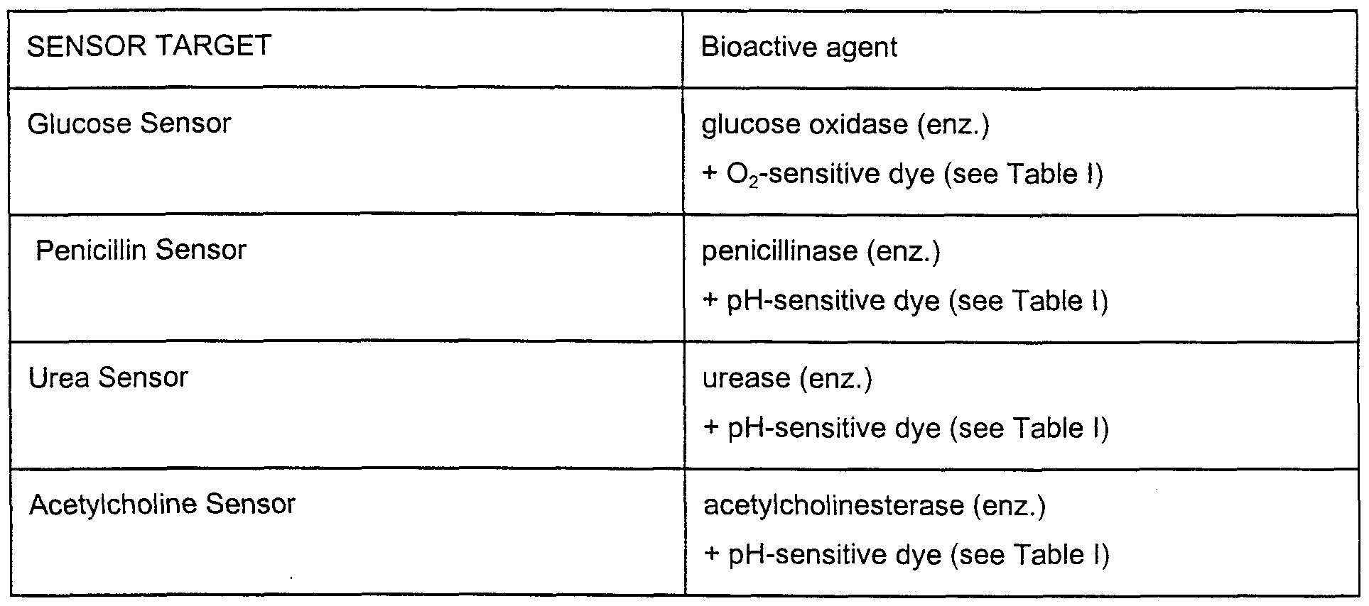

Claims
Priority Applications (13)
| Application Number | Priority Date | Filing Date | Title |
|---|---|---|---|
| CA002305545A CA2305545C (en) | 1997-10-06 | 1998-10-06 | Self-encoding fiber optic sensor |
| DE69841805T DE69841805D1 (en) | 1997-10-06 | 1998-10-06 | SELF-ENCODING FIBER OPTIC SENSOR |
| AT98956096T ATE476653T1 (en) | 1997-10-06 | 1998-10-06 | SELF-ENCODING FIBER OPTICAL SENSOR |
| JP2000515177A JP4471493B2 (en) | 1997-10-06 | 1998-10-06 | Analytical chemical sensor arrays and their uses |
| EP98956096A EP1021718B1 (en) | 1997-10-06 | 1998-10-06 | Self-encoding fiber optic sensor |
| AU12695/99A AU755141B2 (en) | 1997-10-06 | 1998-10-06 | Self-encoding fiber optic sensor |
| US09/287,573 US7348181B2 (en) | 1997-10-06 | 1999-04-06 | Self-encoding sensor with microspheres |
| AU2003200922A AU2003200922B8 (en) | 1997-10-06 | 2003-03-05 | Self-encoding fiber optic sensor |
| US11/040,504 US7754498B2 (en) | 1997-10-06 | 2005-01-21 | Self-encoding sensor with microspheres |
| US12/834,422 US8030094B2 (en) | 1997-10-06 | 2010-07-12 | Self-encoding sensor with microspheres |
| US13/215,749 US8426217B2 (en) | 1997-10-06 | 2011-08-23 | Self-encoding sensor with microspheres |
| US13/850,154 US8691591B2 (en) | 1997-10-06 | 2013-03-25 | Self-encoding sensor with microspheres |
| US14/179,135 US9157113B2 (en) | 1997-10-06 | 2014-02-12 | Self-encoding sensor with microspheres |
Applications Claiming Priority (2)
| Application Number | Priority Date | Filing Date | Title |
|---|---|---|---|
| US08/944,850 | 1997-10-06 | ||
| US08/944,850 US7115884B1 (en) | 1997-10-06 | 1997-10-06 | Self-encoding fiber optic sensor |
Related Parent Applications (1)
| Application Number | Title | Priority Date | Filing Date |
|---|---|---|---|
| US08/944,850 Continuation-In-Part US7115884B1 (en) | 1997-10-06 | 1997-10-06 | Self-encoding fiber optic sensor |
Related Child Applications (2)
| Application Number | Title | Priority Date | Filing Date |
|---|---|---|---|
| US08/944,850 Continuation-In-Part US7115884B1 (en) | 1997-10-06 | 1997-10-06 | Self-encoding fiber optic sensor |
| US09/287,573 Continuation-In-Part US7348181B2 (en) | 1997-10-06 | 1999-04-06 | Self-encoding sensor with microspheres |
Publications (2)
| Publication Number | Publication Date |
|---|---|
| WO1999018434A1 true WO1999018434A1 (en) | 1999-04-15 |
| WO1999018434A9 WO1999018434A9 (en) | 1999-08-05 |
Family
ID=25482172
Family Applications (1)
| Application Number | Title | Priority Date | Filing Date |
|---|---|---|---|
| PCT/US1998/021193 WO1999018434A1 (en) | 1997-10-06 | 1998-10-06 | Self-encoding fiber optic sensor |
Country Status (8)
| Country | Link |
|---|---|
| US (1) | US7115884B1 (en) |
| EP (2) | EP2230512A1 (en) |
| JP (3) | JP4471493B2 (en) |
| AT (1) | ATE476653T1 (en) |
| AU (1) | AU755141B2 (en) |
| CA (1) | CA2305545C (en) |
| DE (1) | DE69841805D1 (en) |
| WO (1) | WO1999018434A1 (en) |
Cited By (64)
| Publication number | Priority date | Publication date | Assignee | Title |
|---|---|---|---|---|
| WO1999045357A2 (en) * | 1998-03-02 | 1999-09-10 | Trustees Of Tufts College | Biosensor array comprising cell populations confined to microcavities |
| WO1999067641A2 (en) | 1998-06-24 | 1999-12-29 | Illumina, Inc. | Decoding of array sensors with microspheres |
| WO2000004372A1 (en) * | 1998-07-16 | 2000-01-27 | The Board Of Regents, The University Of Texas System | Sensor arrays for the measurement and identification of multiple analytes in solutions |
| WO2000060332A2 (en) * | 1999-04-06 | 2000-10-12 | Trustees Of Tufts College | Self-encoding sensor with microspheres |
| WO2000063437A2 (en) | 1999-04-20 | 2000-10-26 | Illumina, Inc. | Detection of nucleic acid reactions on bead arrays |
| WO2001018524A2 (en) * | 1999-08-30 | 2001-03-15 | Illumina, Inc. | Methods for improving signal detection from an array |
| US6266459B1 (en) | 1997-03-14 | 2001-07-24 | Trustees Of Tufts College | Fiber optic sensor with encoded microspheres |
| WO2001061043A2 (en) * | 2000-02-16 | 2001-08-23 | Illumina, Inc. | Parallel genotyping of multiple patient samples |
| FR2806164A1 (en) * | 2000-03-08 | 2001-09-14 | Thomas Wren Ebbesen | Chemical and/or biochemical detection device using sensitive balls threaded onto a fibre grid which forms a circuit |
| US6327410B1 (en) | 1997-03-14 | 2001-12-04 | The Trustees Of Tufts College | Target analyte sensors utilizing Microspheres |
| US6355431B1 (en) | 1999-04-20 | 2002-03-12 | Illumina, Inc. | Detection of nucleic acid amplification reactions using bead arrays |
| WO2002028530A2 (en) * | 2000-10-06 | 2002-04-11 | Trustees Of Tufts College | Self-encoding sensor arrays with microspheres |
| US6387707B1 (en) | 1996-04-25 | 2002-05-14 | Bioarray Solutions | Array Cytometry |
| US6468811B1 (en) | 1996-04-25 | 2002-10-22 | Bioarray Solutions | Light-controlled electrokinetic assembly of particles near surfaces |
| US6544732B1 (en) | 1999-05-20 | 2003-04-08 | Illumina, Inc. | Encoding and decoding of array sensors utilizing nanocrystals |
| WO2003031979A1 (en) * | 2001-10-05 | 2003-04-17 | Surmodics, Inc. | Randomly ordered arrays and methods of making and using |
| US6573089B1 (en) | 1999-01-08 | 2003-06-03 | Applera Corporation | Method for using and making a fiber array |
| US6589779B1 (en) * | 1999-07-16 | 2003-07-08 | Board Of Regents, The University Of Texas System | General signaling protocol for chemical receptors in immobilized matrices |
| US6620584B1 (en) | 1999-05-20 | 2003-09-16 | Illumina | Combinatorial decoding of random nucleic acid arrays |
| US6713258B2 (en) | 2000-03-29 | 2004-03-30 | Center For The Application Of Molecular Biology To International Agriculture (Cambia) | Methods for genotyping by hybridization analysis |
| US6770441B2 (en) | 2000-02-10 | 2004-08-03 | Illumina, Inc. | Array compositions and methods of making same |
| US6858394B1 (en) | 1998-12-28 | 2005-02-22 | Illumina, Inc. | Composite arrays utilizing microspheres |
| US6890741B2 (en) | 2000-02-07 | 2005-05-10 | Illumina, Inc. | Multiplexed detection of analytes |
| US6913884B2 (en) | 2001-08-16 | 2005-07-05 | Illumina, Inc. | Compositions and methods for repetitive use of genomic DNA |
| WO2006010768A1 (en) * | 2004-07-28 | 2006-02-02 | Iee International Electronics & Engineering S.A. | Detection and analysis of optical sensing probes |
| US7041510B2 (en) * | 1996-04-25 | 2006-05-09 | Bioarray Solutions Ltd. | System and method for programmable illumination pattern generation |
| US7057704B2 (en) * | 2000-09-17 | 2006-06-06 | Bioarray Solutions Ltd. | System and method for programmable illumination pattern generation |
| US7083914B2 (en) | 1997-05-23 | 2006-08-01 | Bioarray Solutions Ltd. | Color-encoding and in-situ interrogation of matrix-coupled chemical compounds |
| US7115884B1 (en) | 1997-10-06 | 2006-10-03 | Trustees Of Tufts College | Self-encoding fiber optic sensor |
| US7291504B2 (en) * | 1996-04-25 | 2007-11-06 | Bioarray Solutions Ltd. | Assay involving detection and identification with encoded particles |
| US7335153B2 (en) | 2001-12-28 | 2008-02-26 | Bio Array Solutions Ltd. | Arrays of microparticles and methods of preparation thereof |
| EP1307743B1 (en) * | 2000-05-04 | 2008-12-24 | The Center for Blood Research, INC. | Colloid compositions for solid phase biomolecular analytical systems |
| US7595189B2 (en) | 1999-01-08 | 2009-09-29 | Applied Biosystems, Llc | Integrated optics fiber array |
| US7604996B1 (en) | 1999-08-18 | 2009-10-20 | Illumina, Inc. | Compositions and methods for preparing oligonucleotide solutions |
| US7781226B2 (en) | 2004-02-27 | 2010-08-24 | The Board Of Regents Of The University Of Texas System | Particle on membrane assay system |
| EP2230314A1 (en) * | 2000-01-31 | 2010-09-22 | The Board of Regents,The University of Texas System | Method of sensing an analyte |
| US7887752B2 (en) | 2003-01-21 | 2011-02-15 | Illumina, Inc. | Chemical reaction monitor |
| US8080380B2 (en) | 1999-05-21 | 2011-12-20 | Illumina, Inc. | Use of microfluidic systems in the detection of target analytes using microsphere arrays |
| WO2011159942A1 (en) | 2010-06-18 | 2011-12-22 | Illumina, Inc. | Conformational probes and methods for sequencing nucleic acids |
| US8150626B2 (en) | 2003-05-15 | 2012-04-03 | Illumina, Inc. | Methods and compositions for diagnosing lung cancer with specific DNA methylation patterns |
| US8150627B2 (en) | 2003-05-15 | 2012-04-03 | Illumina, Inc. | Methods and compositions for diagnosing lung cancer with specific DNA methylation patterns |
| WO2013096661A1 (en) | 2011-12-22 | 2013-06-27 | Illumina, Inc. | Methylation biomarkers for ovarian cancer |
| US8481268B2 (en) | 1999-05-21 | 2013-07-09 | Illumina, Inc. | Use of microfluidic systems in the detection of target analytes using microsphere arrays |
| US8709788B2 (en) | 2002-09-16 | 2014-04-29 | The Board Of Trustees Of The Leland Stanford Junior University | Biological analysis arrangement and approach therefor |
| US8735172B2 (en) | 2000-10-19 | 2014-05-27 | Biocartis S.A. | Method and device for the manipulation of microcarriers for an identification purpose |
| US8939376B1 (en) | 1999-04-16 | 2015-01-27 | Mycartis Nv | Encoding of microcarriers |
| US9377388B2 (en) | 1997-03-14 | 2016-06-28 | Trustees Of Tufts College | Methods for detecting target analytes and enzymatic reactions |
| US9637777B2 (en) | 2003-10-28 | 2017-05-02 | Bioarray Solutions, Ltd. | Optimization of gene expression analysis using immobilized capture probes |
| US9709559B2 (en) | 2000-06-21 | 2017-07-18 | Bioarray Solutions, Ltd. | Multianalyte molecular analysis using application-specific random particle arrays |
| US9714937B2 (en) | 2009-10-13 | 2017-07-25 | Nanostring Technologies, Inc. | Protein detection via nanoreporters |
| US9714446B2 (en) | 2010-02-11 | 2017-07-25 | Nanostring Technologies, Inc. | Compositions and methods for the detection of small RNAs |
| US9758834B2 (en) | 2011-03-28 | 2017-09-12 | Nanostring Technologies, Inc. | Compositions and methods for diagnosing cancer |
| US9850536B2 (en) | 2000-02-07 | 2017-12-26 | Illumina, Inc. | Multiplex nucleic acid reactions |
| US9856519B2 (en) | 2008-08-14 | 2018-01-02 | Nanostring Technologies, Inc. | Stable nanoreporters |
| US9890419B2 (en) | 2005-12-23 | 2018-02-13 | Nanostring Technologies, Inc. | Nanoreporters and methods of manufacturing and use thereof |
| US9920380B2 (en) | 2001-07-03 | 2018-03-20 | The Institute For Systems Biology | Methods for detection and quantification of analytes in complex mixtures |
| US10107804B2 (en) | 2001-03-23 | 2018-10-23 | Trustees Of Tufts College | Methods for detecting target analytes and enzymatic reactions |
| US10415081B2 (en) | 2001-10-15 | 2019-09-17 | Bioarray Solutions Ltd. | Multiplexed analysis of polymorphic loci by concurrent interrogation and enzyme-mediated detection |
| US10415080B2 (en) | 2016-11-21 | 2019-09-17 | Nanostring Technologies, Inc. | Chemical compositions and methods of using same |
| US10501777B2 (en) | 2015-07-17 | 2019-12-10 | Nanostring Technologies, Inc. | Simultaneous quantification of a plurality of proteins in a user-defined region of a cross-sectioned tissue |
| US10640816B2 (en) | 2015-07-17 | 2020-05-05 | Nanostring Technologies, Inc. | Simultaneous quantification of gene expression in a user-defined region of a cross-sectioned tissue |
| EP3798321A1 (en) | 2015-12-17 | 2021-03-31 | Illumina, Inc. | Distinguishing methylation levels in complex biological samples |
| US11377689B2 (en) | 2018-02-12 | 2022-07-05 | Nanostring Technologies, Inc. | Chemical compositions and uses thereof |
| US11549139B2 (en) | 2018-05-14 | 2023-01-10 | Nanostring Technologies, Inc. | Chemical compositions and methods of using same |
Families Citing this family (90)
| Publication number | Priority date | Publication date | Assignee | Title |
|---|---|---|---|---|
| US6406848B1 (en) | 1997-05-23 | 2002-06-18 | Lynx Therapeutics, Inc. | Planar arrays of microparticle-bound polynucleotides |
| USRE43097E1 (en) | 1994-10-13 | 2012-01-10 | Illumina, Inc. | Massively parallel signature sequencing by ligation of encoded adaptors |
| US9155496B2 (en) | 1997-03-04 | 2015-10-13 | Dexcom, Inc. | Low oxygen in vivo analyte sensor |
| US7899511B2 (en) | 2004-07-13 | 2011-03-01 | Dexcom, Inc. | Low oxygen in vivo analyte sensor |
| US8527026B2 (en) | 1997-03-04 | 2013-09-03 | Dexcom, Inc. | Device and method for determining analyte levels |
| US6862465B2 (en) | 1997-03-04 | 2005-03-01 | Dexcom, Inc. | Device and method for determining analyte levels |
| US6001067A (en) | 1997-03-04 | 1999-12-14 | Shults; Mark C. | Device and method for determining analyte levels |
| US8974386B2 (en) | 1998-04-30 | 2015-03-10 | Abbott Diabetes Care Inc. | Analyte monitoring device and methods of use |
| US8688188B2 (en) | 1998-04-30 | 2014-04-01 | Abbott Diabetes Care Inc. | Analyte monitoring device and methods of use |
| US8346337B2 (en) | 1998-04-30 | 2013-01-01 | Abbott Diabetes Care Inc. | Analyte monitoring device and methods of use |
| US9066695B2 (en) | 1998-04-30 | 2015-06-30 | Abbott Diabetes Care Inc. | Analyte monitoring device and methods of use |
| US8480580B2 (en) | 1998-04-30 | 2013-07-09 | Abbott Diabetes Care Inc. | Analyte monitoring device and methods of use |
| US6949816B2 (en) | 2003-04-21 | 2005-09-27 | Motorola, Inc. | Semiconductor component having first surface area for electrically coupling to a semiconductor chip and second surface area for electrically coupling to a substrate, and method of manufacturing same |
| US8465425B2 (en) | 1998-04-30 | 2013-06-18 | Abbott Diabetes Care Inc. | Analyte monitoring device and methods of use |
| US6175752B1 (en) | 1998-04-30 | 2001-01-16 | Therasense, Inc. | Analyte monitoring device and methods of use |
| US7612020B2 (en) * | 1998-12-28 | 2009-11-03 | Illumina, Inc. | Composite arrays utilizing microspheres with a hybridization chamber |
| US20060275782A1 (en) | 1999-04-20 | 2006-12-07 | Illumina, Inc. | Detection of nucleic acid reactions on bead arrays |
| US8076063B2 (en) | 2000-02-07 | 2011-12-13 | Illumina, Inc. | Multiplexed methylation detection methods |
| US7955794B2 (en) | 2000-09-21 | 2011-06-07 | Illumina, Inc. | Multiplex nucleic acid reactions |
| US6759235B2 (en) | 2000-04-06 | 2004-07-06 | Quantum Dot Corporation | Two-dimensional spectral imaging system |
| DE60117556T2 (en) * | 2000-06-21 | 2006-11-02 | Bioarray Solutions Ltd. | MULTI-ANALYTIC MOLECULAR ANALYSIS THROUGH THE USE OF APPLICATION SPECIFIC RAPID PARTICLE ARRAYS |
| US6560471B1 (en) | 2001-01-02 | 2003-05-06 | Therasense, Inc. | Analyte monitoring device and methods of use |
| EP1397068A2 (en) | 2001-04-02 | 2004-03-17 | Therasense, Inc. | Blood glucose tracking apparatus and methods |
| US7262063B2 (en) | 2001-06-21 | 2007-08-28 | Bio Array Solutions, Ltd. | Directed assembly of functional heterostructures |
| US20030032874A1 (en) | 2001-07-27 | 2003-02-13 | Dexcom, Inc. | Sensor head for use with implantable devices |
| AU2003298655A1 (en) | 2002-11-15 | 2004-06-15 | Bioarray Solutions, Ltd. | Analysis, secure access to, and transmission of array images |
| US7134999B2 (en) | 2003-04-04 | 2006-11-14 | Dexcom, Inc. | Optimized sensor geometry for an implantable glucose sensor |
| US7074307B2 (en) | 2003-07-25 | 2006-07-11 | Dexcom, Inc. | Electrode systems for electrochemical sensors |
| US7761130B2 (en) | 2003-07-25 | 2010-07-20 | Dexcom, Inc. | Dual electrode system for a continuous analyte sensor |
| US7494465B2 (en) | 2004-07-13 | 2009-02-24 | Dexcom, Inc. | Transcutaneous analyte sensor |
| US20190357827A1 (en) | 2003-08-01 | 2019-11-28 | Dexcom, Inc. | Analyte sensor |
| US7774145B2 (en) | 2003-08-01 | 2010-08-10 | Dexcom, Inc. | Transcutaneous analyte sensor |
| US8676287B2 (en) | 2003-08-01 | 2014-03-18 | Dexcom, Inc. | System and methods for processing analyte sensor data |
| US20080119703A1 (en) | 2006-10-04 | 2008-05-22 | Mark Brister | Analyte sensor |
| US8160669B2 (en) | 2003-08-01 | 2012-04-17 | Dexcom, Inc. | Transcutaneous analyte sensor |
| US8275437B2 (en) | 2003-08-01 | 2012-09-25 | Dexcom, Inc. | Transcutaneous analyte sensor |
| US7778680B2 (en) | 2003-08-01 | 2010-08-17 | Dexcom, Inc. | System and methods for processing analyte sensor data |
| US7920906B2 (en) | 2005-03-10 | 2011-04-05 | Dexcom, Inc. | System and methods for processing analyte sensor data for sensor calibration |
| US7927796B2 (en) | 2003-09-18 | 2011-04-19 | Bioarray Solutions, Ltd. | Number coding for identification of subtypes of coded types of solid phase carriers |
| CN1882699A (en) | 2003-09-22 | 2006-12-20 | 佰尔瑞溶液有限公司 | Surface immobilized polyelectrolyte with multiple functional groups capable of covalently bonding to biomolecules |
| ES2533876T3 (en) | 2003-10-29 | 2015-04-15 | Bioarray Solutions Ltd | Multiplexed nucleic acid analysis by double stranded DNA fragmentation |
| US9247900B2 (en) | 2004-07-13 | 2016-02-02 | Dexcom, Inc. | Analyte sensor |
| US8287453B2 (en) | 2003-12-05 | 2012-10-16 | Dexcom, Inc. | Analyte sensor |
| US8364231B2 (en) | 2006-10-04 | 2013-01-29 | Dexcom, Inc. | Analyte sensor |
| US11633133B2 (en) | 2003-12-05 | 2023-04-25 | Dexcom, Inc. | Dual electrode system for a continuous analyte sensor |
| EP2256493B1 (en) | 2003-12-05 | 2014-02-26 | DexCom, Inc. | Calibration techniques for a continuous analyte sensor |
| US8423114B2 (en) | 2006-10-04 | 2013-04-16 | Dexcom, Inc. | Dual electrode system for a continuous analyte sensor |
| US7637868B2 (en) * | 2004-01-12 | 2009-12-29 | Dexcom, Inc. | Composite material for implantable device |
| US8792955B2 (en) | 2004-05-03 | 2014-07-29 | Dexcom, Inc. | Transcutaneous analyte sensor |
| US8886272B2 (en) | 2004-07-13 | 2014-11-11 | Dexcom, Inc. | Analyte sensor |
| US7783333B2 (en) | 2004-07-13 | 2010-08-24 | Dexcom, Inc. | Transcutaneous medical device with variable stiffness |
| US8452368B2 (en) | 2004-07-13 | 2013-05-28 | Dexcom, Inc. | Transcutaneous analyte sensor |
| US20070045902A1 (en) | 2004-07-13 | 2007-03-01 | Brauker James H | Analyte sensor |
| US8565848B2 (en) | 2004-07-13 | 2013-10-22 | Dexcom, Inc. | Transcutaneous analyte sensor |
| US8170803B2 (en) | 2004-07-13 | 2012-05-01 | Dexcom, Inc. | Transcutaneous analyte sensor |
| US7848889B2 (en) | 2004-08-02 | 2010-12-07 | Bioarray Solutions, Ltd. | Automated analysis of multiplexed probe-target interaction patterns: pattern matching and allele identification |
| WO2006047038A1 (en) * | 2004-09-28 | 2006-05-04 | Trustees Of Tufts College | Apparatus and method for cell migration assays |
| US8133178B2 (en) | 2006-02-22 | 2012-03-13 | Dexcom, Inc. | Analyte sensor |
| US20090076360A1 (en) | 2007-09-13 | 2009-03-19 | Dexcom, Inc. | Transcutaneous analyte sensor |
| US20060246576A1 (en) | 2005-04-06 | 2006-11-02 | Affymetrix, Inc. | Fluidic system and method for processing biological microarrays in personal instrumentation |
| US8486629B2 (en) | 2005-06-01 | 2013-07-16 | Bioarray Solutions, Ltd. | Creation of functionalized microparticle libraries by oligonucleotide ligation or elongation |
| US7595473B2 (en) * | 2005-08-22 | 2009-09-29 | Tufts University | Method and system of array imaging |
| US9757061B2 (en) | 2006-01-17 | 2017-09-12 | Dexcom, Inc. | Low oxygen in vivo analyte sensor |
| US8492098B2 (en) * | 2006-02-21 | 2013-07-23 | The Trustees Of Tufts College | Methods and arrays for target analyte detection and determination of reaction components that affect a reaction |
| US11237171B2 (en) | 2006-02-21 | 2022-02-01 | Trustees Of Tufts College | Methods and arrays for target analyte detection and determination of target analyte concentration in solution |
| CA2653761C (en) * | 2006-06-02 | 2014-07-29 | Luminex Corporation | Systems and methods for performing measurements of one or more materials |
| US7920907B2 (en) | 2006-06-07 | 2011-04-05 | Abbott Diabetes Care Inc. | Analyte monitoring system and method |
| US7831287B2 (en) | 2006-10-04 | 2010-11-09 | Dexcom, Inc. | Dual electrode system for a continuous analyte sensor |
| WO2008063901A1 (en) * | 2006-11-17 | 2008-05-29 | Trustees Of Boston University | Nanochannel-based sensor system for use in detecting chemical or biological species |
| US7813013B2 (en) * | 2006-11-21 | 2010-10-12 | Illumina, Inc. | Hexagonal site line scanning method and system |
| US20080274458A1 (en) * | 2007-05-01 | 2008-11-06 | Latham Gary J | Nucleic acid quantitation methods |
| US20110195852A1 (en) * | 2007-08-30 | 2011-08-11 | Trustees Of Tufts College | Methods for determining the concentration of an analyte in solution |
| US8417312B2 (en) | 2007-10-25 | 2013-04-09 | Dexcom, Inc. | Systems and methods for processing sensor data |
| US8396528B2 (en) | 2008-03-25 | 2013-03-12 | Dexcom, Inc. | Analyte sensor |
| US20100075862A1 (en) * | 2008-09-23 | 2010-03-25 | Quanterix Corporation | High sensitivity determination of the concentration of analyte molecules or particles in a fluid sample |
| US8222047B2 (en) | 2008-09-23 | 2012-07-17 | Quanterix Corporation | Ultra-sensitive detection of molecules on single molecule arrays |
| US20100075439A1 (en) * | 2008-09-23 | 2010-03-25 | Quanterix Corporation | Ultra-sensitive detection of molecules by capture-and-release using reducing agents followed by quantification |
| US8965076B2 (en) | 2010-01-13 | 2015-02-24 | Illumina, Inc. | Data processing system and methods |
| US9678068B2 (en) | 2010-03-01 | 2017-06-13 | Quanterix Corporation | Ultra-sensitive detection of molecules using dual detection methods |
| US8415171B2 (en) | 2010-03-01 | 2013-04-09 | Quanterix Corporation | Methods and systems for extending dynamic range in assays for the detection of molecules or particles |
| US8236574B2 (en) | 2010-03-01 | 2012-08-07 | Quanterix Corporation | Ultra-sensitive detection of molecules or particles using beads or other capture objects |
| JP5363663B2 (en) | 2010-03-01 | 2013-12-11 | クワンテリクス コーポレーション | Method or system for extending the dynamic range in an assay to detect molecules or particles |
| US8483969B2 (en) | 2010-09-17 | 2013-07-09 | Illuminia, Inc. | Variation analysis for multiple templates on a solid support |
| US9952237B2 (en) | 2011-01-28 | 2018-04-24 | Quanterix Corporation | Systems, devices, and methods for ultra-sensitive detection of molecules or particles |
| US20140302532A1 (en) | 2011-04-12 | 2014-10-09 | Quanterix Corporation | Methods of determining a treatment protocol for and/or a prognosis of a patient's recovery from a brain injury |
| DK3575796T3 (en) | 2011-04-15 | 2021-01-18 | Dexcom Inc | ADVANCED ANALYZE SENSOR CALIBRATION AND ERROR DETECTION |
| US9932626B2 (en) | 2013-01-15 | 2018-04-03 | Quanterix Corporation | Detection of DNA or RNA using single molecule arrays and other techniques |
| WO2015148367A1 (en) * | 2014-03-26 | 2015-10-01 | Drexel University | Chemically switchable ultraviolet photoluminescence |
| WO2017112025A2 (en) * | 2015-10-05 | 2017-06-29 | The University Of North Carolina At Chapel Hill | Decoding methods for multiplexing assays and associated fluidic devices, kits, and solid supports |
| CN114615499B (en) * | 2022-05-07 | 2022-09-16 | 北京邮电大学 | Semantic optical communication system and method for image transmission |
Citations (9)
| Publication number | Priority date | Publication date | Assignee | Title |
|---|---|---|---|---|
| US4499052A (en) * | 1982-08-30 | 1985-02-12 | Becton, Dickinson And Company | Apparatus for distinguishing multiple subpopulations of cells |
| US4822746A (en) * | 1986-06-25 | 1989-04-18 | Trustees Of Tufts College | Radiative and non-radiative energy transfer and absorbance modulated fluorescence detection methods and sensors |
| US5028545A (en) * | 1987-06-16 | 1991-07-02 | Wallac Oy | Biospecific multianalyte assay method |
| US5244636A (en) * | 1991-01-25 | 1993-09-14 | Trustees Of Tufts College | Imaging fiber optic array sensors, apparatus, and methods for concurrently detecting multiple analytes of interest in a fluid sample |
| US5308771A (en) * | 1992-04-13 | 1994-05-03 | Geo-Centers, Inc. | Chemical sensors |
| WO1994012863A1 (en) * | 1992-11-25 | 1994-06-09 | Trustees Of Tufts College | Fiber optic array sensors and methods for concurrently visualizing and chemically detecting multiple analytes in a fluid |
| GB2294319A (en) * | 1994-10-20 | 1996-04-24 | Cambridge Imaging Ltd | Detecting the position of labelled material in an image |
| EP0723146A1 (en) * | 1992-09-14 | 1996-07-24 | Sri International | Up-converting reporters for biological and other assays using laser excitation techniques |
| WO1997012030A1 (en) * | 1995-09-27 | 1997-04-03 | Nanogen, Inc. | Apparatus and methods for active programmable matrix devices |
Family Cites Families (97)
| Publication number | Priority date | Publication date | Assignee | Title |
|---|---|---|---|---|
| US4200110A (en) | 1977-11-28 | 1980-04-29 | United States Of America | Fiber optic pH probe |
| US4469863A (en) | 1980-11-12 | 1984-09-04 | Ts O Paul O P | Nonionic nucleic acid alkyl and aryl phosphonates and processes for manufacture and use thereof |
| US5034506A (en) | 1985-03-15 | 1991-07-23 | Anti-Gene Development Group | Uncharged morpholino-based polymers having achiral intersubunit linkages |
| US5235033A (en) | 1985-03-15 | 1993-08-10 | Anti-Gene Development Group | Alpha-morpholino ribonucleoside derivatives and polymers thereof |
| US4682895A (en) | 1985-08-06 | 1987-07-28 | Texas A&M University | Fiber optic probe for quantification of colorimetric reactions |
| US4798738A (en) | 1986-10-10 | 1989-01-17 | Cardiovascular Devices, Inc. | Micro sensor |
| US4824789B1 (en) | 1986-10-10 | 1996-08-13 | Minnesota Mining & Mfg | Gas sensor |
| US5254477A (en) | 1986-06-25 | 1993-10-19 | Trustees Of Tufts College | Flourescence intramolecular energy transfer conjugate compositions and detection methods |
| US5143853A (en) | 1986-06-25 | 1992-09-01 | Trustees Of Tufts College | Absorbance modulated fluorescence detection methods and sensors |
| US5252494A (en) | 1986-06-25 | 1993-10-12 | Trustees Of Tufts College | Fiber optic sensors, apparatus, and detection methods using controlled release polymers and reagent formulations held within a polymeric reaction matrix |
| US5114864A (en) | 1986-06-25 | 1992-05-19 | Trustees Of Tufts College | Fiber optic sensors, apparatus, and detection methods using fluid erodible controlled release polymers for delivery of reagent formulations |
| DE3681176D1 (en) | 1986-12-01 | 1991-10-02 | Molecular Biosystems Inc | METHOD FOR INCREASING THE SENSITIVITY OF NUCLEIC ACID HYBRIDIZATION TESTS. |
| US5132242A (en) | 1987-07-15 | 1992-07-21 | Cheung Sau W | Fluorescent microspheres and methods of using them |
| US5194300A (en) | 1987-07-15 | 1993-03-16 | Cheung Sau W | Methods of making fluorescent microspheres |
| US4785814A (en) | 1987-08-11 | 1988-11-22 | Cordis Corporation | Optical probe for measuring pH and oxygen in blood and employing a composite membrane |
| US5002867A (en) | 1988-04-25 | 1991-03-26 | Macevicz Stephen C | Nucleic acid sequence determination by multiple mixed oligonucleotide probes |
| NO164622C (en) | 1988-05-11 | 1990-10-24 | Tore Lindmo | BINAER IMMUNOMETRIC PARTICLE-BASED METHOD FOR MEASURING SPECIFIC SERUM ANTIGENS USING LIQUID FLOW MICROPHOTOMETRY AND A PREPARED TARGET SET UP THEREOF. |
| US5216141A (en) | 1988-06-06 | 1993-06-01 | Benner Steven A | Oligonucleotide analogs containing sulfur linkages |
| US5575849A (en) | 1988-11-25 | 1996-11-19 | Canon Kabushiki Kaisha | Apparatus for producing a substrate having a surface with a plurality of spherical dimples for photoconductive members |
| EP0392546A3 (en) | 1989-04-14 | 1991-09-11 | Ro Institut Za Molekularnu Genetiku I Geneticko Inzenjerstvo | Process for determination of a complete or a partial contents of very short sequences in the samples of nucleic acids connected to the discrete particles of microscopic size by hybridization with oligonucleotide probes |
| US5302509A (en) | 1989-08-14 | 1994-04-12 | Beckman Instruments, Inc. | Method for sequencing polynucleotides |
| US5326692B1 (en) | 1992-05-13 | 1996-04-30 | Molecular Probes Inc | Fluorescent microparticles with controllable enhanced stokes shift |
| US5494810A (en) | 1990-05-03 | 1996-02-27 | Cornell Research Foundation, Inc. | Thermostable ligase-mediated DNA amplifications system for the detection of genetic disease |
| US5602240A (en) | 1990-07-27 | 1997-02-11 | Ciba Geigy Ag. | Backbone modified oligonucleotide analogs |
| US5386023A (en) | 1990-07-27 | 1995-01-31 | Isis Pharmaceuticals | Backbone modified oligonucleotide analogs and preparation thereof through reductive coupling |
| DE69125441T2 (en) | 1990-09-28 | 1997-11-06 | Toshiba Kawasaki Kk | Gene detection method |
| EP0557456A4 (en) | 1990-11-14 | 1995-11-15 | Siska Diagnostics Inc | Non-isotopic detection of nucleic acids using a polystyrene support-based sandwich hybridization assay and compositions useful therefor |
| JP3181609B2 (en) * | 1990-12-28 | 2001-07-03 | 株式会社島津製作所 | Photodetector for capillary chromatography |
| US5105305A (en) | 1991-01-10 | 1992-04-14 | At&T Bell Laboratories | Near-field scanning optical microscope using a fluorescent probe |
| US5244813A (en) | 1991-01-25 | 1993-09-14 | Trustees Of Tufts College | Fiber optic sensor, apparatus, and methods for detecting an organic analyte in a fluid or vapor sample |
| US5250264A (en) | 1991-01-25 | 1993-10-05 | Trustees Of Tufts College | Method of making imaging fiber optic sensors to concurrently detect multiple analytes of interest in a fluid sample |
| US5380489A (en) | 1992-02-18 | 1995-01-10 | Eastman Kodak Company | Element and method for nucleic acid amplification and detection using adhered probes |
| AU647609B2 (en) * | 1991-04-18 | 1994-03-24 | Becton Dickinson & Company | Microbial monitoring device |
| CA2113350C (en) | 1991-07-16 | 1999-03-23 | Brian C. Lehnen | Methods and compositions for simultaneous analysis of multiple analytes |
| US5639603A (en) | 1991-09-18 | 1997-06-17 | Affymax Technologies N.V. | Synthesizing and screening molecular diversity |
| EP0608370B1 (en) | 1991-10-15 | 1998-01-07 | Multilyte Limited | Binding assay employing labelled reagent |
| US6051380A (en) | 1993-11-01 | 2000-04-18 | Nanogen, Inc. | Methods and procedures for molecular biological analysis and diagnostics |
| US5644048A (en) | 1992-01-10 | 1997-07-01 | Isis Pharmaceuticals, Inc. | Process for preparing phosphorothioate oligonucleotides |
| US5888723A (en) | 1992-02-18 | 1999-03-30 | Johnson & Johnson Clinical Diagnostics, Inc. | Method for nucleic acid amplification and detection using adhered probes |
| EP0565999A2 (en) | 1992-04-16 | 1993-10-20 | Siemens Aktiengesellschaft | Optical coupling device for two groups of waveguides |
| ATE140025T1 (en) * | 1992-05-01 | 1996-07-15 | Univ Pennsylvania | MICRO-MADE DEVICES FOR SPERM HANDLING |
| JPH06509946A (en) | 1992-06-17 | 1994-11-10 | シティ・オブ・ホープ | How to detect and identify nucleic acids |
| JP3311752B2 (en) | 1992-07-02 | 2002-08-05 | ソイニ,エルッキ | Biospecific multivariable test method |
| US5372783A (en) * | 1992-08-03 | 1994-12-13 | Sapidyne, Inc. | Assay system |
| US5565324A (en) | 1992-10-01 | 1996-10-15 | The Trustees Of Columbia University In The City Of New York | Complex combinatorial chemical libraries encoded with tags |
| US5298741A (en) | 1993-01-13 | 1994-03-29 | Trustees Of Tufts College | Thin film fiber optic sensor array and apparatus for concurrent viewing and chemical sensing of a sample |
| CA2102884A1 (en) | 1993-03-04 | 1994-09-05 | James J. Wynne | Dental procedures and apparatus using ultraviolet radiation |
| JP3302458B2 (en) | 1993-08-31 | 2002-07-15 | 富士通株式会社 | Integrated optical device and manufacturing method |
| US5494798A (en) | 1993-12-09 | 1996-02-27 | Gerdt; David W. | Fiber optic evanscent wave sensor for immunoassay |
| US5496997A (en) | 1994-01-03 | 1996-03-05 | Pope; Edward J. A. | Sensor incorporating an optical fiber and a solid porous inorganic microsphere |
| JP3175110B2 (en) | 1994-02-07 | 2001-06-11 | オーキッド・バイオサイエンシーズ・インコーポレイテッド | Genetic bit analysis of ligase / polymerase mediated single nucleotide polymorphisms and their use in genetic analysis |
| US5637684A (en) | 1994-02-23 | 1997-06-10 | Isis Pharmaceuticals, Inc. | Phosphoramidate and phosphorothioamidate oligomeric compounds |
| US5856083A (en) | 1994-05-06 | 1999-01-05 | Pharmacopeia, Inc. | Lawn assay for compounds that affect enzyme activity or bind to target molecules |
| WO1996003212A1 (en) | 1994-07-26 | 1996-02-08 | Sydney Brenner | Multidimensional conduit combinatorial library synthesis device |
| US5512490A (en) | 1994-08-11 | 1996-04-30 | Trustees Of Tufts College | Optical sensor, optical sensing apparatus, and methods for detecting an analyte of interest using spectral recognition patterns |
| US6406848B1 (en) | 1997-05-23 | 2002-06-18 | Lynx Therapeutics, Inc. | Planar arrays of microparticle-bound polynucleotides |
| US5846719A (en) | 1994-10-13 | 1998-12-08 | Lynx Therapeutics, Inc. | Oligonucleotide tags for sorting and identification |
| US5585069A (en) | 1994-11-10 | 1996-12-17 | David Sarnoff Research Center, Inc. | Partitioned microelectronic and fluidic device array for clinical diagnostics and chemical synthesis |
| US5866434A (en) * | 1994-12-08 | 1999-02-02 | Meso Scale Technology | Graphitic nanotubes in luminescence assays |
| DE69620596T2 (en) | 1995-05-19 | 2002-11-21 | Abbott Lab | DETECTION OF NUCLEIC ACIDS WITH A WIDE DYNAMIC RANGE USING AGGREGATE PRIMER ROWS |
| US5690894A (en) | 1995-05-23 | 1997-11-25 | The Regents Of The University Of California | High density array fabrication and readout method for a fiber optic biosensor |
| US5656241A (en) | 1995-09-07 | 1997-08-12 | Optical Sensors Incorporated | Method for manufacturing fiber optic sensors |
| WO1997014028A2 (en) | 1995-10-11 | 1997-04-17 | Luminex Corporation | Multiplexed analysis of clinical specimens apparatus and method |
| GB9521159D0 (en) | 1995-10-16 | 1995-12-20 | Brint Norman T | A weapon |
| US5866331A (en) * | 1995-10-20 | 1999-02-02 | University Of Massachusetts | Single molecule detection by in situ hybridization |
| US5633972A (en) | 1995-11-29 | 1997-05-27 | Trustees Of Tufts College | Superresolution imaging fiber for subwavelength light energy generation and near-field optical microscopy |
| US5814524A (en) | 1995-12-14 | 1998-09-29 | Trustees Of Tufts College | Optical sensor apparatus for far-field viewing and making optical analytical measurements at remote locations |
| JPH09191877A (en) * | 1996-01-17 | 1997-07-29 | Asahi Chem Ind Co Ltd | Porous membrane comprising immobilized enzyme and enzymaticaly catalyzed reaction |
| US5837196A (en) | 1996-01-26 | 1998-11-17 | The Regents Of The University Of California | High density array fabrication and readout method for a fiber optic biosensor |
| AU735440B2 (en) | 1996-02-09 | 2001-07-05 | Cornell Research Foundation Inc. | Detection of nucleic acid sequence differences using the ligase detection reaction with addressable arrays |
| US5840256A (en) | 1996-04-09 | 1998-11-24 | David Sarnoff Research Center Inc. | Plate for reaction system |
| CA2255599C (en) | 1996-04-25 | 2006-09-05 | Bioarray Solutions, Llc | Light-controlled electrokinetic assembly of particles near surfaces |
| EP0912761A4 (en) | 1996-05-29 | 2004-06-09 | Cornell Res Foundation Inc | Detection of nucleic acid sequence differences using coupled ligase detection and polymerase chain reactions |
| US5854684A (en) | 1996-09-26 | 1998-12-29 | Sarnoff Corporation | Massively parallel detection |
| GB9620209D0 (en) | 1996-09-27 | 1996-11-13 | Cemu Bioteknik Ab | Method of sequencing DNA |
| US5900481A (en) | 1996-11-06 | 1999-05-04 | Sequenom, Inc. | Bead linkers for immobilizing nucleic acids to solid supports |
| WO1998029736A1 (en) | 1996-12-31 | 1998-07-09 | Genometrix Incorporated | Multiplexed molecular analysis apparatus and method |
| US6023540A (en) | 1997-03-14 | 2000-02-08 | Trustees Of Tufts College | Fiber optic sensor with encoded microspheres |
| US6327410B1 (en) | 1997-03-14 | 2001-12-04 | The Trustees Of Tufts College | Target analyte sensors utilizing Microspheres |
| AU738708B2 (en) | 1997-05-02 | 2001-09-27 | Gen-Probe Incorporated | Two-step hybridization and capture of a polynucleotide |
| US6406845B1 (en) | 1997-05-05 | 2002-06-18 | Trustees Of Tuft College | Fiber optic biosensor for selectively detecting oligonucleotide species in a mixed fluid sample |
| CA2291853C (en) | 1997-05-23 | 2013-01-15 | Bioarray Solutions Llc | Color-encoding and in-situ interrogation of matrix-coupled chemical compounds |
| US7115884B1 (en) | 1997-10-06 | 2006-10-03 | Trustees Of Tufts College | Self-encoding fiber optic sensor |
| AU4194899A (en) | 1998-05-21 | 1999-12-06 | Hyseq, Inc. | Linear arrays of immobilized compounds and methods of using same |
| EP2045334A1 (en) | 1998-06-24 | 2009-04-08 | Illumina, Inc. | Decoding of array sensors with microspheres |
| EP1090138A4 (en) | 1998-06-24 | 2003-01-02 | Glaxo Group Ltd | Nucleotide detection method |
| US6908770B1 (en) | 1998-07-16 | 2005-06-21 | Board Of Regents, The University Of Texas System | Fluid based analysis of multiple analytes by a sensor array |
| US5998175A (en) | 1998-07-24 | 1999-12-07 | Lumigen, Inc. | Methods of synthesizing and amplifying polynucleotides by ligation of multiple oligomers |
| AU6131299A (en) | 1998-08-26 | 2000-03-21 | Trustees Of Tufts College | Combinatorial polymer synthesis of sensors for polymer-based sensor arrays |
| US6429027B1 (en) | 1998-12-28 | 2002-08-06 | Illumina, Inc. | Composite arrays utilizing microspheres |
| EP1206315A2 (en) | 1999-02-09 | 2002-05-22 | Illumina, Inc. | Arrays comprising a fiducial and automated information processing in randomly ordered arrays |
| JP2002539849A (en) | 1999-03-26 | 2002-11-26 | ホワイトヘッド インスチチュート フォアー バイオメディカル リサーチ | Universal array |
| EP1196630B2 (en) | 1999-04-20 | 2018-10-17 | Illumina, Inc. | Detection of nucleic acid reactions on bead arrays |
| WO2000075373A2 (en) | 1999-05-20 | 2000-12-14 | Illumina, Inc. | Combinatorial decoding of random nucleic acid arrays |
| US6544732B1 (en) | 1999-05-20 | 2003-04-08 | Illumina, Inc. | Encoding and decoding of array sensors utilizing nanocrystals |
| US20020051971A1 (en) | 1999-05-21 | 2002-05-02 | John R. Stuelpnagel | Use of microfluidic systems in the detection of target analytes using microsphere arrays |
| CN102586228A (en) | 1999-09-13 | 2012-07-18 | 纽亘技术公司 | Methods and composition for linear isothermal amplification of polynucleotide sequences |
-
1997
- 1997-10-06 US US08/944,850 patent/US7115884B1/en not_active Expired - Lifetime
-
1998
- 1998-10-06 JP JP2000515177A patent/JP4471493B2/en not_active Expired - Lifetime
- 1998-10-06 DE DE69841805T patent/DE69841805D1/en not_active Expired - Lifetime
- 1998-10-06 CA CA002305545A patent/CA2305545C/en not_active Expired - Lifetime
- 1998-10-06 AU AU12695/99A patent/AU755141B2/en not_active Expired
- 1998-10-06 EP EP10005326A patent/EP2230512A1/en not_active Ceased
- 1998-10-06 EP EP98956096A patent/EP1021718B1/en not_active Expired - Lifetime
- 1998-10-06 AT AT98956096T patent/ATE476653T1/en not_active IP Right Cessation
- 1998-10-06 WO PCT/US1998/021193 patent/WO1999018434A1/en active IP Right Grant
-
2009
- 2009-03-16 JP JP2009062380A patent/JP4550149B2/en not_active Expired - Lifetime
-
2010
- 2010-05-18 JP JP2010114269A patent/JP5220055B2/en not_active Expired - Lifetime
Patent Citations (9)
| Publication number | Priority date | Publication date | Assignee | Title |
|---|---|---|---|---|
| US4499052A (en) * | 1982-08-30 | 1985-02-12 | Becton, Dickinson And Company | Apparatus for distinguishing multiple subpopulations of cells |
| US4822746A (en) * | 1986-06-25 | 1989-04-18 | Trustees Of Tufts College | Radiative and non-radiative energy transfer and absorbance modulated fluorescence detection methods and sensors |
| US5028545A (en) * | 1987-06-16 | 1991-07-02 | Wallac Oy | Biospecific multianalyte assay method |
| US5244636A (en) * | 1991-01-25 | 1993-09-14 | Trustees Of Tufts College | Imaging fiber optic array sensors, apparatus, and methods for concurrently detecting multiple analytes of interest in a fluid sample |
| US5308771A (en) * | 1992-04-13 | 1994-05-03 | Geo-Centers, Inc. | Chemical sensors |
| EP0723146A1 (en) * | 1992-09-14 | 1996-07-24 | Sri International | Up-converting reporters for biological and other assays using laser excitation techniques |
| WO1994012863A1 (en) * | 1992-11-25 | 1994-06-09 | Trustees Of Tufts College | Fiber optic array sensors and methods for concurrently visualizing and chemically detecting multiple analytes in a fluid |
| GB2294319A (en) * | 1994-10-20 | 1996-04-24 | Cambridge Imaging Ltd | Detecting the position of labelled material in an image |
| WO1997012030A1 (en) * | 1995-09-27 | 1997-04-03 | Nanogen, Inc. | Apparatus and methods for active programmable matrix devices |
Non-Patent Citations (5)
| Title |
|---|
| CORDOR ET AL., SCIENCE, vol. 261, 1993 |
| J.W. GRATE ET AL., ANAL. CHEM., vol. 68, 1996, pages 913 - 7 |
| R.A. MCGILL ET AL., CHEMTECH, 24 September 1996 (1996-09-24), pages 27 - 37 |
| SCHAFER ET AL., NATURE BIOTECHNOLOGY, vol. 16, 1998, pages 33 - 39 |
| WANG ET AL., SCIENCE, vol. 280, 1998, pages 1077 |
Cited By (124)
| Publication number | Priority date | Publication date | Assignee | Title |
|---|---|---|---|---|
| US7041510B2 (en) * | 1996-04-25 | 2006-05-09 | Bioarray Solutions Ltd. | System and method for programmable illumination pattern generation |
| US6387707B1 (en) | 1996-04-25 | 2002-05-14 | Bioarray Solutions | Array Cytometry |
| US7749774B2 (en) * | 1996-04-25 | 2010-07-06 | Michael Seul | Arrays formed of encoded beads having ligands attached |
| US7427512B2 (en) * | 1996-04-25 | 2008-09-23 | Bioarray Solutions Ltd. | Light-controlled electrokinetic assembly of particles near surfaces |
| US7056746B2 (en) * | 1996-04-25 | 2006-06-06 | Bioarray Solutions Ltd. | Array cytometry |
| US7291504B2 (en) * | 1996-04-25 | 2007-11-06 | Bioarray Solutions Ltd. | Assay involving detection and identification with encoded particles |
| US7615345B2 (en) | 1996-04-25 | 2009-11-10 | Bio Array Solutions Ltd. | Arrays formed of encoded beads having oligonucleotides attached |
| US6514771B1 (en) | 1996-04-25 | 2003-02-04 | Bioarray Solutions | Light-controlled electrokinetic assembly of particles near surfaces |
| US6468811B1 (en) | 1996-04-25 | 2002-10-22 | Bioarray Solutions | Light-controlled electrokinetic assembly of particles near surfaces |
| US9377388B2 (en) | 1997-03-14 | 2016-06-28 | Trustees Of Tufts College | Methods for detecting target analytes and enzymatic reactions |
| US6327410B1 (en) | 1997-03-14 | 2001-12-04 | The Trustees Of Tufts College | Target analyte sensors utilizing Microspheres |
| US10241026B2 (en) | 1997-03-14 | 2019-03-26 | Trustees Of Tufts College | Target analyte sensors utilizing microspheres |
| US6266459B1 (en) | 1997-03-14 | 2001-07-24 | Trustees Of Tufts College | Fiber optic sensor with encoded microspheres |
| US6859570B2 (en) | 1997-03-14 | 2005-02-22 | Trustees Of Tufts College, Tufts University | Target analyte sensors utilizing microspheres |
| US7083914B2 (en) | 1997-05-23 | 2006-08-01 | Bioarray Solutions Ltd. | Color-encoding and in-situ interrogation of matrix-coupled chemical compounds |
| US9945051B2 (en) | 1997-05-23 | 2018-04-17 | Rutgers, The State University Of New Jersey | Color-encoding and in-situ interrogation of matrix-coupled chemical compounds |
| US8030094B2 (en) | 1997-10-06 | 2011-10-04 | Trustees Of Tufts College | Self-encoding sensor with microspheres |
| US8426217B2 (en) | 1997-10-06 | 2013-04-23 | Trustees Of Tufts College | Self-encoding sensor with microspheres |
| US7754498B2 (en) | 1997-10-06 | 2010-07-13 | Trustees Of Tufts College | Self-encoding sensor with microspheres |
| US9157113B2 (en) | 1997-10-06 | 2015-10-13 | Trustees Of Tufts College, Tufts University | Self-encoding sensor with microspheres |
| US7115884B1 (en) | 1997-10-06 | 2006-10-03 | Trustees Of Tufts College | Self-encoding fiber optic sensor |
| US8691591B2 (en) | 1997-10-06 | 2014-04-08 | Trustees Of Tufts College | Self-encoding sensor with microspheres |
| US7348181B2 (en) | 1997-10-06 | 2008-03-25 | Trustees Of Tufts College | Self-encoding sensor with microspheres |
| US6667159B1 (en) | 1998-03-02 | 2003-12-23 | Trustees Of Tufts College | Optical fiber biosensor array comprising cell populations confined to microcavities |
| WO1999045357A3 (en) * | 1998-03-02 | 2000-04-27 | Tufts College | Biosensor array comprising cell populations confined to microcavities |
| WO1999045357A2 (en) * | 1998-03-02 | 1999-09-10 | Trustees Of Tufts College | Biosensor array comprising cell populations confined to microcavities |
| US6377721B1 (en) | 1998-03-02 | 2002-04-23 | Trustees Of Tufts College | Biosensor array comprising cell populations confined to microcavities |
| EP2360271A1 (en) * | 1998-06-24 | 2011-08-24 | Illumina, Inc. | Decoding of array sensors with microspheres |
| WO1999067641A2 (en) | 1998-06-24 | 1999-12-29 | Illumina, Inc. | Decoding of array sensors with microspheres |
| WO1999067641A3 (en) * | 1998-06-24 | 2000-03-09 | Illumina Inc | Decoding of array sensors with microspheres |
| EP2045334A1 (en) * | 1998-06-24 | 2009-04-08 | Illumina, Inc. | Decoding of array sensors with microspheres |
| WO2000004372A1 (en) * | 1998-07-16 | 2000-01-27 | The Board Of Regents, The University Of Texas System | Sensor arrays for the measurement and identification of multiple analytes in solutions |
| EP1593967A3 (en) * | 1998-12-28 | 2007-04-25 | Illumina, Inc. | Composite arrays utilising microspheres |
| US6998274B2 (en) | 1998-12-28 | 2006-02-14 | Illumina, Inc. | Composite arrays utilizing microspheres |
| US6858394B1 (en) | 1998-12-28 | 2005-02-22 | Illumina, Inc. | Composite arrays utilizing microspheres |
| US6982149B2 (en) | 1999-01-08 | 2006-01-03 | Applera Corporation | Fiber array and methods for using and making same |
| US7595189B2 (en) | 1999-01-08 | 2009-09-29 | Applied Biosystems, Llc | Integrated optics fiber array |
| US6649404B1 (en) | 1999-01-08 | 2003-11-18 | Applera Corporation | Method for using and making a fiber array |
| US6573089B1 (en) | 1999-01-08 | 2003-06-03 | Applera Corporation | Method for using and making a fiber array |
| WO2000060332A3 (en) * | 1999-04-06 | 2001-05-31 | Tufts College | Self-encoding sensor with microspheres |
| WO2000060332A2 (en) * | 1999-04-06 | 2000-10-12 | Trustees Of Tufts College | Self-encoding sensor with microspheres |
| US8939376B1 (en) | 1999-04-16 | 2015-01-27 | Mycartis Nv | Encoding of microcarriers |
| US8967483B2 (en) | 1999-04-16 | 2015-03-03 | Mycartis Nv | Encoding of microcarriers |
| EP1923472A1 (en) | 1999-04-20 | 2008-05-21 | Illumina, Inc. | Detection of nucleic acid reactions on bead arrays |
| WO2000063437A3 (en) * | 1999-04-20 | 2002-01-17 | Illumina Inc | Detection of nucleic acid reactions on bead arrays |
| EP1923471A1 (en) | 1999-04-20 | 2008-05-21 | Illumina, Inc. | Detection of nucleic acid reactions on bead arrays |
| EP2264189A1 (en) * | 1999-04-20 | 2010-12-22 | Illumina, Inc. | Detection of nucleic acid reactions on bead arrays |
| WO2000063437A2 (en) | 1999-04-20 | 2000-10-26 | Illumina, Inc. | Detection of nucleic acid reactions on bead arrays |
| US6355431B1 (en) | 1999-04-20 | 2002-03-12 | Illumina, Inc. | Detection of nucleic acid amplification reactions using bead arrays |
| US7166431B2 (en) | 1999-05-20 | 2007-01-23 | Illumina, Inc. | Combinatorial decoding of random nucleic acid arrays |
| US7563576B2 (en) | 1999-05-20 | 2009-07-21 | Illumina, Inc. | Combinatorial decoding of random nucleic acid arrays |
| US6620584B1 (en) | 1999-05-20 | 2003-09-16 | Illumina | Combinatorial decoding of random nucleic acid arrays |
| US6544732B1 (en) | 1999-05-20 | 2003-04-08 | Illumina, Inc. | Encoding and decoding of array sensors utilizing nanocrystals |
| EP2360270A1 (en) * | 1999-05-20 | 2011-08-24 | Illumina, Inc. | Combinatorial decoding of random nucleic acid arrays |
| US7960119B2 (en) | 1999-05-20 | 2011-06-14 | Illumina, Inc. | Combinatorial decoding of random nucleic acid arrays |
| US8206917B2 (en) | 1999-05-20 | 2012-06-26 | Illumina, Inc. | Combinatorial decoding of random nucleic acid arrays |
| US9163283B2 (en) | 1999-05-20 | 2015-10-20 | Illumina, Inc. | Combinatorial decoding of random nucleic acid arrays |
| US8563246B2 (en) | 1999-05-20 | 2013-10-22 | Illumina, Inc. | Combinatorial decoding of random nucleic acid arrays |
| US8481268B2 (en) | 1999-05-21 | 2013-07-09 | Illumina, Inc. | Use of microfluidic systems in the detection of target analytes using microsphere arrays |
| US9289766B2 (en) | 1999-05-21 | 2016-03-22 | Illumina, Inc. | Use of microfluidic systems in the detection of target analytes using microsphere arrays |
| US8883424B2 (en) | 1999-05-21 | 2014-11-11 | Illumina, Inc. | Use of microfluidic systems in the detection of target analytes using microsphere arrays |
| US8080380B2 (en) | 1999-05-21 | 2011-12-20 | Illumina, Inc. | Use of microfluidic systems in the detection of target analytes using microsphere arrays |
| US6589779B1 (en) * | 1999-07-16 | 2003-07-08 | Board Of Regents, The University Of Texas System | General signaling protocol for chemical receptors in immobilized matrices |
| US7604996B1 (en) | 1999-08-18 | 2009-10-20 | Illumina, Inc. | Compositions and methods for preparing oligonucleotide solutions |
| US9745573B2 (en) | 1999-08-18 | 2017-08-29 | Illumina, Inc. | Compositions and methods for preparing oligonucleotide solutions |
| WO2001018524A2 (en) * | 1999-08-30 | 2001-03-15 | Illumina, Inc. | Methods for improving signal detection from an array |
| US6942968B1 (en) | 1999-08-30 | 2005-09-13 | Illumina, Inc. | Array compositions for improved signal detection |
| WO2001018524A3 (en) * | 1999-08-30 | 2002-02-21 | Illumina Inc | Methods for improving signal detection from an array |
| EP2230314A1 (en) * | 2000-01-31 | 2010-09-22 | The Board of Regents,The University of Texas System | Method of sensing an analyte |
| US9850536B2 (en) | 2000-02-07 | 2017-12-26 | Illumina, Inc. | Multiplex nucleic acid reactions |
| US6890741B2 (en) | 2000-02-07 | 2005-05-10 | Illumina, Inc. | Multiplexed detection of analytes |
| US10837059B2 (en) | 2000-02-07 | 2020-11-17 | Illumina, Inc. | Multiplex nucleic acid reactions |
| US6770441B2 (en) | 2000-02-10 | 2004-08-03 | Illumina, Inc. | Array compositions and methods of making same |
| EP1967595A2 (en) | 2000-02-16 | 2008-09-10 | Illumina, Inc. | Parallel genotyping of multiple patient samples |
| WO2001061043A3 (en) * | 2000-02-16 | 2002-08-08 | Illumina Inc | Parallel genotyping of multiple patient samples |
| US7285384B2 (en) | 2000-02-16 | 2007-10-23 | Illuminia, Inc. | Parallel genotyping of multiple patient samples |
| WO2001061043A2 (en) * | 2000-02-16 | 2001-08-23 | Illumina, Inc. | Parallel genotyping of multiple patient samples |
| EP1967595A3 (en) * | 2000-02-16 | 2008-12-03 | Illumina, Inc. | Parallel genotyping of multiple patient samples |
| FR2806164A1 (en) * | 2000-03-08 | 2001-09-14 | Thomas Wren Ebbesen | Chemical and/or biochemical detection device using sensitive balls threaded onto a fibre grid which forms a circuit |
| US6713258B2 (en) | 2000-03-29 | 2004-03-30 | Center For The Application Of Molecular Biology To International Agriculture (Cambia) | Methods for genotyping by hybridization analysis |
| EP1307743B1 (en) * | 2000-05-04 | 2008-12-24 | The Center for Blood Research, INC. | Colloid compositions for solid phase biomolecular analytical systems |
| US9709559B2 (en) | 2000-06-21 | 2017-07-18 | Bioarray Solutions, Ltd. | Multianalyte molecular analysis using application-specific random particle arrays |
| US7057704B2 (en) * | 2000-09-17 | 2006-06-06 | Bioarray Solutions Ltd. | System and method for programmable illumination pattern generation |
| WO2002028530A3 (en) * | 2000-10-06 | 2002-12-27 | Tufts College | Self-encoding sensor arrays with microspheres |
| WO2002028530A2 (en) * | 2000-10-06 | 2002-04-11 | Trustees Of Tufts College | Self-encoding sensor arrays with microspheres |
| US8735172B2 (en) | 2000-10-19 | 2014-05-27 | Biocartis S.A. | Method and device for the manipulation of microcarriers for an identification purpose |
| US10107804B2 (en) | 2001-03-23 | 2018-10-23 | Trustees Of Tufts College | Methods for detecting target analytes and enzymatic reactions |
| US9920380B2 (en) | 2001-07-03 | 2018-03-20 | The Institute For Systems Biology | Methods for detection and quantification of analytes in complex mixtures |
| US6913884B2 (en) | 2001-08-16 | 2005-07-05 | Illumina, Inc. | Compositions and methods for repetitive use of genomic DNA |
| US7195913B2 (en) | 2001-10-05 | 2007-03-27 | Surmodics, Inc. | Randomly ordered arrays and methods of making and using |
| WO2003031979A1 (en) * | 2001-10-05 | 2003-04-17 | Surmodics, Inc. | Randomly ordered arrays and methods of making and using |
| US10415081B2 (en) | 2001-10-15 | 2019-09-17 | Bioarray Solutions Ltd. | Multiplexed analysis of polymorphic loci by concurrent interrogation and enzyme-mediated detection |
| US9611507B2 (en) | 2001-12-28 | 2017-04-04 | Bioarray Solutions, Ltd. | Arrays of microparticles and methods of preparation thereof |
| US7335153B2 (en) | 2001-12-28 | 2008-02-26 | Bio Array Solutions Ltd. | Arrays of microparticles and methods of preparation thereof |
| US10138511B2 (en) | 2001-12-28 | 2018-11-27 | Bioarray Solutions Ltd. | Arrays of microparticles and methods of preparation thereof |
| US8709788B2 (en) | 2002-09-16 | 2014-04-29 | The Board Of Trustees Of The Leland Stanford Junior University | Biological analysis arrangement and approach therefor |
| US8592214B2 (en) | 2003-01-21 | 2013-11-26 | Illumina, Inc. | Chemical reaction monitor |
| US7887752B2 (en) | 2003-01-21 | 2011-02-15 | Illumina, Inc. | Chemical reaction monitor |
| US8150627B2 (en) | 2003-05-15 | 2012-04-03 | Illumina, Inc. | Methods and compositions for diagnosing lung cancer with specific DNA methylation patterns |
| US8150626B2 (en) | 2003-05-15 | 2012-04-03 | Illumina, Inc. | Methods and compositions for diagnosing lung cancer with specific DNA methylation patterns |
| US9637777B2 (en) | 2003-10-28 | 2017-05-02 | Bioarray Solutions, Ltd. | Optimization of gene expression analysis using immobilized capture probes |
| US7781226B2 (en) | 2004-02-27 | 2010-08-24 | The Board Of Regents Of The University Of Texas System | Particle on membrane assay system |
| WO2006010768A1 (en) * | 2004-07-28 | 2006-02-02 | Iee International Electronics & Engineering S.A. | Detection and analysis of optical sensing probes |
| US7643145B2 (en) | 2004-07-28 | 2010-01-05 | Iee International Electronics & Engineering S.A. | Detection and analysis of optical sensing probes |
| US9890419B2 (en) | 2005-12-23 | 2018-02-13 | Nanostring Technologies, Inc. | Nanoreporters and methods of manufacturing and use thereof |
| US9856519B2 (en) | 2008-08-14 | 2018-01-02 | Nanostring Technologies, Inc. | Stable nanoreporters |
| US10077466B2 (en) | 2008-08-14 | 2018-09-18 | Nanostring Technologies, Inc. | Stable nanoreporters |
| US9995739B2 (en) | 2009-10-13 | 2018-06-12 | Nanostring Technologies, Inc. | Protein detection via nanoreporters |
| US9714937B2 (en) | 2009-10-13 | 2017-07-25 | Nanostring Technologies, Inc. | Protein detection via nanoreporters |
| US9714446B2 (en) | 2010-02-11 | 2017-07-25 | Nanostring Technologies, Inc. | Compositions and methods for the detection of small RNAs |
| WO2011159942A1 (en) | 2010-06-18 | 2011-12-22 | Illumina, Inc. | Conformational probes and methods for sequencing nucleic acids |
| US9758834B2 (en) | 2011-03-28 | 2017-09-12 | Nanostring Technologies, Inc. | Compositions and methods for diagnosing cancer |
| WO2013096661A1 (en) | 2011-12-22 | 2013-06-27 | Illumina, Inc. | Methylation biomarkers for ovarian cancer |
| US10501777B2 (en) | 2015-07-17 | 2019-12-10 | Nanostring Technologies, Inc. | Simultaneous quantification of a plurality of proteins in a user-defined region of a cross-sectioned tissue |
| US10640816B2 (en) | 2015-07-17 | 2020-05-05 | Nanostring Technologies, Inc. | Simultaneous quantification of gene expression in a user-defined region of a cross-sectioned tissue |
| US11708602B2 (en) | 2015-07-17 | 2023-07-25 | Nanostring Technologies, Inc. | Simultaneous quantification of gene expression in a user-defined region of a cross-sectioned tissue |
| EP3798321A1 (en) | 2015-12-17 | 2021-03-31 | Illumina, Inc. | Distinguishing methylation levels in complex biological samples |
| US11319593B2 (en) | 2015-12-17 | 2022-05-03 | Illumina, Inc. | Distinguishing methylation levels in complex biological samples |
| US10415080B2 (en) | 2016-11-21 | 2019-09-17 | Nanostring Technologies, Inc. | Chemical compositions and methods of using same |
| US11279969B2 (en) | 2016-11-21 | 2022-03-22 | Nanostring Technologies, Inc. | Chemical compositions and methods of using same |
| US11821026B2 (en) | 2016-11-21 | 2023-11-21 | Nanostring Technologies, Inc. | Chemical compositions and methods of using same |
| US11377689B2 (en) | 2018-02-12 | 2022-07-05 | Nanostring Technologies, Inc. | Chemical compositions and uses thereof |
| US11473142B2 (en) | 2018-02-12 | 2022-10-18 | Nanostring Technologies, Inc. | Chemical compositions and uses thereof |
| US11549139B2 (en) | 2018-05-14 | 2023-01-10 | Nanostring Technologies, Inc. | Chemical compositions and methods of using same |
Also Published As
| Publication number | Publication date |
|---|---|
| JP5220055B2 (en) | 2013-06-26 |
| JP4471493B2 (en) | 2010-06-02 |
| CA2305545A1 (en) | 1999-04-15 |
| JP2010249826A (en) | 2010-11-04 |
| AU1269599A (en) | 1999-04-27 |
| ATE476653T1 (en) | 2010-08-15 |
| AU755141B2 (en) | 2002-12-05 |
| EP2230512A1 (en) | 2010-09-22 |
| WO1999018434A9 (en) | 1999-08-05 |
| EP1021718B1 (en) | 2010-08-04 |
| EP1021718A1 (en) | 2000-07-26 |
| US7115884B1 (en) | 2006-10-03 |
| JP2009180735A (en) | 2009-08-13 |
| JP2001519530A (en) | 2001-10-23 |
| JP4550149B2 (en) | 2010-09-22 |
| DE69841805D1 (en) | 2010-09-16 |
| CA2305545C (en) | 2006-11-21 |
Similar Documents
| Publication | Publication Date | Title |
|---|---|---|
| AU755141B2 (en) | Self-encoding fiber optic sensor | |
| US9157113B2 (en) | Self-encoding sensor with microspheres | |
| US10241026B2 (en) | Target analyte sensors utilizing microspheres | |
| US6327410B1 (en) | Target analyte sensors utilizing Microspheres | |
| US20050090021A1 (en) | Self-encoding sensor with microspheres | |
| AU2003200922B8 (en) | Self-encoding fiber optic sensor | |
| AU2005200653A8 (en) | Self-encoding sensor with microspheres |
Legal Events
| Date | Code | Title | Description |
|---|---|---|---|
| AK | Designated states |
Kind code of ref document: A1 Designated state(s): AL AM AT AU AZ BA BB BG BR BY CA CH CN CU CZ DE DK EE ES FI GB GD GE GH GM HR HU ID IL IS JP KE KG KP KR KZ LC LK LR LS LT LU LV MD MG MK MN MW MX NO NZ PL PT RO RU SD SE SG SI SK SL TJ TM TR TT UA UG US UZ VN YU ZW |
|
| AL | Designated countries for regional patents |
Kind code of ref document: A1 Designated state(s): GH GM KE LS MW SD SZ UG ZW AM AZ BY KG KZ MD RU TJ TM AT BE CH CY DE DK ES FI FR GB GR IE IT LU MC NL PT SE BF BJ CF CG CI CM GA GN GW ML MR NE SN TD TG |
|
| 121 | Ep: the epo has been informed by wipo that ep was designated in this application | ||
| DFPE | Request for preliminary examination filed prior to expiration of 19th month from priority date (pct application filed before 20040101) | ||
| AK | Designated states |
Kind code of ref document: C2 Designated state(s): AL AM AT AU AZ BA BB BG BR BY CA CH CN CU CZ DE DK EE ES FI GB GD GE GH GM HR HU ID IL IS JP KE KG KP KR KZ LC LK LR LS LT LU LV MD MG MK MN MW MX NO NZ PL PT RO RU SD SE SG SI SK SL TJ TM TR TT UA UG US UZ VN YU ZW |
|
| AL | Designated countries for regional patents |
Kind code of ref document: C2 Designated state(s): GH GM KE LS MW SD SZ UG ZW AM AZ BY KG KZ MD RU TJ TM AT BE CH CY DE DK ES FI FR GB GR IE IT LU MC NL PT SE BF BJ CF CG CI CM GA GN GW ML MR NE SN TD TG |
|
| COP | Corrected version of pamphlet |
Free format text: PAGES 1-49, DESCRIPTION, REPLACED BY NEW PAGES 1-49; PAGES 50-57, CLAIMS, REPLACED BY NEW PAGES 50-57; PAGES 1/20-20/20, DRAWINGS, REPLACED BY NEW PAGES 1/20-20/20; DUE TO LATE TRANSMITTAL BY THE RECEIVING OFFICE |
|
| ENP | Entry into the national phase |
Ref document number: 2305545 Country of ref document: CA Ref country code: CA Ref document number: 2305545 Kind code of ref document: A Format of ref document f/p: F |
|
| ENP | Entry into the national phase |
Ref country code: JP Ref document number: 2000 515177 Kind code of ref document: A Format of ref document f/p: F |
|
| NENP | Non-entry into the national phase |
Ref country code: KR |
|
| WWE | Wipo information: entry into national phase |
Ref document number: 12695/99 Country of ref document: AU |
|
| WWE | Wipo information: entry into national phase |
Ref document number: 1998956096 Country of ref document: EP |
|
| WWP | Wipo information: published in national office |
Ref document number: 1998956096 Country of ref document: EP |
|
| REG | Reference to national code |
Ref country code: DE Ref legal event code: 8642 |
|
| WWG | Wipo information: grant in national office |
Ref document number: 12695/99 Country of ref document: AU |