US9722400B2 - Application and maintenance of tension to transmission line in pipe - Google Patents
Application and maintenance of tension to transmission line in pipe Download PDFInfo
- Publication number
- US9722400B2 US9722400B2 US13/929,470 US201313929470A US9722400B2 US 9722400 B2 US9722400 B2 US 9722400B2 US 201313929470 A US201313929470 A US 201313929470A US 9722400 B2 US9722400 B2 US 9722400B2
- Authority
- US
- United States
- Prior art keywords
- transmission line
- tension
- sleeve
- load
- pipe
- Prior art date
- Legal status (The legal status is an assumption and is not a legal conclusion. Google has not performed a legal analysis and makes no representation as to the accuracy of the status listed.)
- Active, expires
Links
Images


Classifications
-
- H—ELECTRICITY
- H02—GENERATION; CONVERSION OR DISTRIBUTION OF ELECTRIC POWER
- H02G—INSTALLATION OF ELECTRIC CABLES OR LINES, OR OF COMBINED OPTICAL AND ELECTRIC CABLES OR LINES
- H02G3/00—Installations of electric cables or lines or protective tubing therefor in or on buildings, equivalent structures or vehicles
- H02G3/02—Details
-
- E—FIXED CONSTRUCTIONS
- E21—EARTH DRILLING; MINING
- E21B—EARTH DRILLING, e.g. DEEP DRILLING; OBTAINING OIL, GAS, WATER, SOLUBLE OR MELTABLE MATERIALS OR A SLURRY OF MINERALS FROM WELLS
- E21B17/00—Drilling rods or pipes; Flexible drill strings; Kellies; Drill collars; Sucker rods; Cables; Casings; Tubings
- E21B17/003—Drilling rods or pipes; Flexible drill strings; Kellies; Drill collars; Sucker rods; Cables; Casings; Tubings with electrically conducting or insulating means
-
- E—FIXED CONSTRUCTIONS
- E21—EARTH DRILLING; MINING
- E21B—EARTH DRILLING, e.g. DEEP DRILLING; OBTAINING OIL, GAS, WATER, SOLUBLE OR MELTABLE MATERIALS OR A SLURRY OF MINERALS FROM WELLS
- E21B17/00—Drilling rods or pipes; Flexible drill strings; Kellies; Drill collars; Sucker rods; Cables; Casings; Tubings
- E21B17/20—Flexible or articulated drilling pipes, e.g. flexible or articulated rods, pipes or cables
- E21B17/206—Flexible or articulated drilling pipes, e.g. flexible or articulated rods, pipes or cables with conductors, e.g. electrical, optical
-
- H—ELECTRICITY
- H02—GENERATION; CONVERSION OR DISTRIBUTION OF ELECTRIC POWER
- H02G—INSTALLATION OF ELECTRIC CABLES OR LINES, OR OF COMBINED OPTICAL AND ELECTRIC CABLES OR LINES
- H02G1/00—Methods or apparatus specially adapted for installing, maintaining, repairing or dismantling electric cables or lines
- H02G1/06—Methods or apparatus specially adapted for installing, maintaining, repairing or dismantling electric cables or lines for laying cables, e.g. laying apparatus on vehicle
-
- Y—GENERAL TAGGING OF NEW TECHNOLOGICAL DEVELOPMENTS; GENERAL TAGGING OF CROSS-SECTIONAL TECHNOLOGIES SPANNING OVER SEVERAL SECTIONS OF THE IPC; TECHNICAL SUBJECTS COVERED BY FORMER USPC CROSS-REFERENCE ART COLLECTIONS [XRACs] AND DIGESTS
- Y10—TECHNICAL SUBJECTS COVERED BY FORMER USPC
- Y10T—TECHNICAL SUBJECTS COVERED BY FORMER US CLASSIFICATION
- Y10T29/00—Metal working
- Y10T29/49—Method of mechanical manufacture
- Y10T29/49826—Assembling or joining
Definitions
- transmission lines that extend along well pipes.
- the transmission lines may be damaged by fluids and debris flowing through the well pipe.
- the method includes inserting a transmission line into a transmission line channel of a pipe.
- the transmission line has a first end and a second end, the transmission line being inserted into a first end of the pipe second-end-first.
- the transmission line has a first tension-load-supporting mechanism attached to the first end of the transmission line.
- the method includes applying a first level of tension to the transmission line in the pipe and applying a second tension-load-supporting mechanism to the second end of the transmission line while the first level of tension is applied to the transmission line.
- the method further includes removing the first level of tension from the transmission line to maintain a second level of tension along the transmission line between the first and second tension-load-supporting mechanisms.
- the pipe assembly includes a pipe having a main cavity extending through the pipe along a longitudinal axis and a transmission line channel located radially outward from the main cavity and extending through the pipe substantially parallel to the longitudinal axis.
- the transmission line channel has a first shoulder at a first end of the transmission line channel and a second shoulder at a second end of the transmission line channel.
- the transmission line assembly includes a transmission line extending along the transmission line channel, a first tension-load-bearing mechanism at a first end of the transmission line and a second tension-load-bearing mechanism at a second end of the transmission line.
- the first tension-load-bearing mechanism and the second tension-load-bearing mechanism are configured to press against the first shoulder and the second shoulder, respectively, to maintain a tension along the transmission line.
- FIG. 1 illustrates a pipe segment according to an embodiment of the invention
- FIG. 2A illustrates one end of a pipe segment according to an embodiment of the invention
- FIG. 2B illustrates another end of a pipe segment according to an embodiment of the invention
- FIG. 3 illustrates a transmission line according to an embodiment of the invention
- FIG. 4 illustrates the insertion of a transmission line into a pipe according to an embodiment of the invention
- FIG. 5 illustrates the insertion of the transmission line into the pipe according to an embodiment of the invention
- FIG. 6 illustrates the insertion of a tension-generating device into a pipe according to an embodiment of the invention
- FIG. 7A illustrates the generation of tension in a transmission line according to an embodiment of the invention
- FIG. 7B illustrates a constriction of a constriction sleeve according to an embodiment of the invention
- FIG. 7C illustrates the constriction of the constriction sleeve according to an embodiment of the invention
- FIG. 8 illustrates a well pipe assembly having the tension-generating device removed according to an embodiment of the invention
- FIG. 9 illustrates the insertion of connectors and a transmission element into the well pipe according to an embodiment of the invention.
- FIG. 10 illustrates the final configuration of the transmission line assembly, connectors and transmission element according to an embodiment of the invention
- FIG. 11 illustrates the application of axial load sleeves and a transmission element on to an end of two transmission lines according to another embodiment of the invention
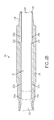
- FIG. 12 illustrates insertion of the transmission lines into the well pipe according to an embodiment of the invention
- FIG. 13 illustrates applying tension to the transmission lines with a tension-generating device according to an embodiment of the invention
- FIG. 14 illustrates a pushing sleeve according to an embodiment of the invention
- FIG. 15 illustrates insertion of axial load sleeves onto an end of two transmission lines according to an embodiment of the invention
- FIG. 16 illustrates attaching sealing sleeves and a transmission element onto the transmission lines according to an embodiment of the invention
- FIG. 17 illustrates the final configuration of the transmission lines, axial load sleeves and transmission element according to an embodiment of the invention
- FIG. 18 illustrates a flow diagram of a method according to an embodiment of the invention.
- FIG. 19 illustrates a pipe segment according to another embodiment of the invention.
- FIG. 1 illustrates a pipe segment 100 according to an embodiment of the invention.
- the pipe segment 100 may be a well pipe segment configured to connect to other well pipe segments to form a pipe in an oil well, or the pipe segment 100 may perform any other purpose.
- the pipe segment 100 includes a pipe body 110 that defines a main cavity 120 .
- the main cavity 120 extends the length of the pipe segment 100 and is configured to permit fluid flow through the pipe segment 100 .
- the main cavity 120 is coaxial with the pipe body 110 .
- the pipe body 110 includes a first end 101 and a second end 102 .
- the first end 101 has a box configuration and the second end 102 has a pin configuration.
- the pin end is configured to fit into a box end of an adjacent pipe segment.
- the pipe segment 100 also includes at least one transmission line cavity.
- a first transmission line cavity 130 is located at the first end 101
- a second transmission line cavity 140 is located at the second end 102 .
- the transmission line cavities 130 and 140 have diameters smaller than the main cavity 120 and are configured to receive a transmission line 150 .
- the pipe body 110 includes a first shoulder 131 in the first transmission line cavity 130 and a second shoulder 141 in the second transmission line cavity 140 .
- the transmission line 150 includes a first tension-load-supporting mechanism 151 that is affixed to the transmission line 150 , such as by welding, by use of a shape memory material, clamping sets, glue, solder, bolts-and-nuts, expansion mandrels, or by use of any other fixing means.
- a diameter of the first tension-load-supporting mechanism 151 is sufficiently large such that an end of the first tension-load-supporting mechanism 151 contacts the first shoulder 131 .
- the transmission line 150 includes a second tension-load-supporting mechanism 152 that is affixed to the transmission line 150 , such as by welding, by use of a shape memory material, clamping sets, glue, solder, bolts-and-nuts, expansion mandrels, or by use of any other fixing means.
- a diameter of the second tension-load-supporting mechanism 152 is sufficiently large such that an end of the second tension-load-supporting mechanism 152 contacts the second shoulder 141 .
- tension force is applied to the transmission line 150 , such that when the tension force is released, the first and second tension-load-supporting mechanism 151 and 152 maintain tension in the transmission line 150 as they press against the first and second shoulders 131 and 141 , respectively.
- a well pipe 210 has a first end 201 and a second end 202 .
- the well pipe 210 may correspond to the well pipe 110 of FIG. 1 .
- the first end 201 may have a box configuration and the second end 202 may have a pin configuration.
- the well pipe 210 defines a main cavity, which may include first and second portions 211 and 212 at the first end 201 , the first and second portions 211 and 212 having different diameters, a center portion 213 between the first end 201 and the second end 202 , and a third portion 231 at the second end 202 . While four different main cavity portions 211 , 212 , 213 and 231 are illustrated in FIGS. 2A and 2B , embodiments of the invention encompass well pipes 210 having any number of main cavity portions having any variety of diameters.
- the first end 201 may include a threaded portion 214 adjacent to the end surface 215
- the second end 202 may include a threaded portion 234 adjacent to the end surface 235 of the second end 202 .
- the threaded portion 214 of the first end 201 may be configured to securely engage with the threaded portion 234 of the second end 202 of an adjacent pipe segment, such that multiple pipe segments may be connected with a fluid-tight seal end-to-end.
- the first end 201 includes a first transmission line channel having a first channel portion 216 a and a second channel portion 217 a .
- the first channel portion 216 a and the second channel portion 217 a are co-axial, and the first channel portion 216 a has a diameter greater than the second channel portion 217 a , such that a shoulder 218 a is located at one end of the first channel portion 216 a where the first channel portion 216 a connects to the second channel portion 217 a .
- the first end 201 also includes a second transmission line channel having a third channel portion 216 b and a fourth channel portion 217 b with a shoulder 218 b between the third and fourth channel portions 216 b and 217 b .
- the second channel portion 217 a has an opening 219 a that opens to the main cavity portion 213
- the fourth channel portion 217 b has an opening 219 b that opens to the main cavity portion 213 .
- a transmission line channel extends from one end of the drill pipe 210 to the other entirely within the wall of the drill pipe 210 , without opening to the main cavity portion 213 .
- the second end 202 includes a third transmission line channel having a fifth channel portion 236 a and a sixth channel portion 237 a that are co-axial.
- the fifth channel portion 236 a has a diameter that is larger than the sixth transmission line portion 237 a
- a shoulder 238 a is located at the end of the fifth channel portion 236 a adjacent to the sixth channel portion 237 a .
- the second end 202 also includes a fourth transmission line channel including a seventh channel portion 236 b , an eighth channel portion 237 b and a shoulder 238 b separating the seventh and eighth channel portions 236 b and 237 b .
- the sixth channel portion 237 a has an opening 239 a that opens to the center main channel portion 213
- the eighth channel portion 237 b has an opening 239 b that opens to the center main channel portion 213 .
- the second end 202 also includes a groove 240 at the end surface 235 , and the fifth and seventh channel portions 236 a and 236 b open into the groove 240 . It should be noted that a similar groove may be present at the first end surface 215 of the first end 201 illustrated in FIG. 2A .
- the first through eighth channel portions 216 a , 216 b , 217 a , 217 b , 236 a , 236 b , 237 a and 237 b are formed in the well pipe 210 radially outward from the main channel of the pipe 210 .
- the first, second, third and fourth channel portions 216 a , 216 b , 217 a and 217 b are located in the pipe 210 radially outward from the second portion 212 of the main channel.
- FIG. 2A the first, second, third and fourth channel portions 216 a , 216 b , 217 a and 217 b are located in the pipe 210 radially outward from the second portion 212 of the main channel.
- the fifth, sixth, seventh and eighth channel portions 236 a , 237 a , 236 b and 237 b are located in the wall of the pipe 210 radially outward from the third portion 231 of the main channel.
- the first through eighth channel portions 216 a , 216 b , 217 a , 217 b , 236 a , 236 b , 237 a and 237 b are physically separated from the second main channel portion 212 and the third main channel portion 231 , respectively, by a wall of the well pipe 210 .
- embodiments of the invention encompass well pipes 210 having any number of transmission line channels, from as few as one transmission line channel, to as many transmission line channels are desired according to design considerations of a particular well pipe.
- FIG. 3 illustrates a transmission line assembly 300 according to an embodiment of the invention.
- the transmission line assembly 300 includes a transmission line 301 , a first axial load sleeve 302 a at a first end of the transmission line 301 and a second axial load sleeve 302 b at a second end of the transmission line 301 .
- a first sealing sleeve 303 a is located on the transmission line 301 at the first end of the transmission line 301
- a second sealing sleeve 303 b is located on the transmission line 301 at the second end of the transmission line 301 .
- the transmission line assembly 300 also includes a stabilizer sleeve 304 .
- the first and second axial load sleeves 302 a and 302 b are fixed with respect to the transmission line 301 .
- the first and second axial load sleeves 302 a and 302 b are welded onto the transmission line 301 .
- the first and second axial load sleeves 302 a and 302 b are configured to receive a force in a direction along the length of the transmission line 301 , having a vector from a center of the transmission line 301 outward toward the ends of the transmission line 301 . Since the axial load sleeves 302 a and 302 b are fixed with respect to the transmission line 301 , they maintain tension along the transmission line 301 in response to receiving the force in the direction along the length of the transmission line 301 .
- the first and second axial load sleeves 302 a and 302 b , the first and second sealing sleeves 303 a and 303 b and the stabilizer sleeve 304 are described in further detail in reference to the figures that follow.
- FIG. 4 illustrates the insertion of the transmission line 301 into the opening defined by the end surface 215 of the well pipe 210 .
- the first axial load sleeve 302 a is attached to the first end of the transmission line 301 .
- the first axial load sleeve 302 a includes a base portion 401 and axially-protruding portions 402 a , 402 b and 402 c separated by spaces 403 a and 403 b .
- the first axial load sleeve 302 a is welded to the transmission line 301 .
- the sealing sleeve 303 a encircles the transmission line 301 at the first end of the transmission line 301 to prevent fluid flow into the first transmission line channel.
- the second end of the transmission line 301 includes an axial load sleeve 302 b and the sealing sleeve 303 b surrounding the transmission line 301 .
- the stabilizer sleeve 304 encircles the transmission line 301 on an opposite side of the axial load sleeve 302 b from the second sealing sleeve 303 b .
- the stabilizer sleeve 304 is used to push the second axial load sleeve 302 b through the well pipe 210 , and in particular in the direction A towards and into the opening 239 a.
- a tension-generating device 600 is inserted into the second end 202 of the well pipe 210 in the direction B.
- the tension-generating device 600 includes a grip portion 601 and an extended portion 602 .
- the grip portion 601 is located at an end of the extended portion 602 .
- the extended portion 602 may be controlled by a control mechanism external to the well pipe 210 to grip and un-grip the transmission line 301 .
- FIG. 7A illustrates the grip portion 601 of the tension-generating device 600 gripping the transmission line 301 and pulling the transmission line 301 in the direction A towards the end of the second portion 202 of the well pipe 210 .
- the tension-generating device 600 pulls the second end of the transmission line 301
- the first axial load sleeve 302 a is pressed up against the shoulder 218 a of the well pipe 210 , which prevents a translation movement of the transmission line 301 , and instead generates tension in the transmission line 301 .
- the second axial load sleeve 302 b is welded or fixed to the transmission line 301 prior to inserting the transmission line into the well pipe 210 .
- the diameter of the axial load sleeve 302 b must be less than the diameter of the opening 239 a and the sixth channel portion 237 a of the third transmission line channel.
- the diameter of the axial load sleeve 302 b is less than the diameter of the sixth channel portion 237 a to permit insertion of the axial load sleeve 302 b into the sixth channel portion 237 a , the axial load sleeve 302 b , alone, is an insufficient structure to maintain tension in the transmission line 301 , since the axial load sleeve 302 b would be freely slideable within the sixth channel portion 237 a.
- transmission line 301 is inserted into first channel 126 a , through the second channel 217 a , through the center portion 213 , and through the sixth channel portion 237 a into the fifth channel portion 236 a
- embodiments of the invention also encompass other methods of inserting the transmission line 301 into the transmission line channels.
- a transmission line is inserted into the center portion 230 of the main cavity, one end is inserted into the second channel 217 a via the opening 219 a and the opposite end is inserted into the sixth channel portion 237 a via the opening 239 a.
- FIG. 7A illustrates the application of a constriction sleeve 701 to the axial load sleeve 302 b to maintain tension in the transmission line 301 .
- the tension-generating device 600 pulls the transmission line in the direction A, and the constriction sleeve 701 and cone sleeve 702 are inserted onto the transmission line 301 .
- the constriction sleeve 701 and cone sleeve 702 may be pushed onto the transmission line by a positioning sleeve 703 .
- FIGS. 7B and 7C illustrate the constriction sleeve 701 and cone sleeve 702 in greater detail.
- FIG. 7B illustrates a state of the transmission line 301 that has been pulled in the direction A until the second axial load sleeve 302 b is located at least a predetermined distance from the shoulder 238 a , where the predetermined distance corresponds to a length of the constriction sleeve 701 .
- the constriction sleeve 701 is then slid over the outside surface of the axial load sleeve 302 b and linearly between the axial load sleeve 302 b and the shoulder 238 a .
- the cone sleeve 702 is then slid over the outer surface of the axial load sleeve 302 b .
- the cone sleeve 702 has a slanted inner surface 704 , such that as the cone sleeve 702 is slid in the direction B, the slanted inner surface 704 causes the constriction sleeve 701 to constrict radially inward. Consequently, as illustrated in FIG.
- an end of the constriction sleeve facing the shoulder 238 a has a diameter greater than the diameter of the fifth channel portion 236 a
- the end of the constriction sleeve facing the axial load sleeve 302 b has an inner diameter less than an outer diameter of the axial load sleeve 302 b.
- the tension generating tool 600 releases its grip of the transmission line 301 , the wider end of the constriction sleeve 701 presses against the shoulder 238 a and the narrower end transmits an axial force, corresponding to the tension of the transmission line 301 , to the second axial load sleeve 302 b .
- a conductive pin or lead 307 extending from the end of the transmission line 301 configured to contact a conductive receptacle of an adjacent connector to transmit data and/or power along the transmission line 301 .
- the tension-generating device 600 is removed from the well pipe 210 and the constriction sleeve 701 is held against the shoulder 138 a by the tension of the transmission line 301 .
- the positioning sleeve 703 may also be removed from the third transmission line channel, and a sealing sleeve 303 b may be inserted over the transmission line 301 to prevent fluid from flowing into the fifth channel portion 236 a .
- a second transmission line assembly 300 b may be inserted into the fourth transmission line channel including the seventh and eighth channel portions 236 b and 237 b by the same manner as the first transmission line assembly 300 a.
- FIG. 6 illustrates only one tension-generating device 600 being inserted into the well pipe 210
- embodiments of the invention encompass any number of tension-generating devices 600 , or any number of grip portions 601 to grip any number of transmission lines 301 simultaneously.
- the tension-generating device 600 may have two grip portions 601 to simultaneously grip the first and second transmission line assemblies 300 a and 300 b.
- FIG. 9 illustrates completion of the transmission system by inserting a first length-adjustable connector 351 a into the second sealing sleeve 303 b , inserting a first guiding sleeve 352 a around an outside of the second sealing sleeve 303 b , and inserting a first transmission line connector 353 a of a transmission element 354 into the guiding sleeve 352 a and sealing sleeve 303 b to contact the length-adjustable connector 351 a .
- data and/or power signals may be transmitted via the transmission line 301 , length-adjustable connector 351 a and transmission line connector 353 a to the transmission element 354 .
- the second transmission line assembly 300 b may also be provided with a length-adjustable connector 351 b , guiding sleeve 352 b and transmission line connector 353 b.
- FIG. 10 illustrates the final tensioned state of the first and second transmission line assemblies 300 a and 300 b , including constriction sleeves 701 a and 701 b , cone sleeves 702 a and 702 b , guiding sleeves 352 a and 352 b , and a transmission element 354 , which is configured to transmit power or data to an adjacent well pipe, such as by electromagnetism.
- embodiments of the invention relate to a system for providing tension in a transmission line of a well pipe, in which a load sleeve is attached to a first end of a transmission line, the transmission line is inserted into a transmission line channel of the well pipe by its second end, the second end is pulled through the transmission line channel, and an axial load-supporting assembly is provided on the second end.
- a load sleeve is attached to a first end of a transmission line
- the transmission line is inserted into a transmission line channel of the well pipe by its second end
- the second end is pulled through the transmission line channel
- an axial load-supporting assembly is provided on the second end.
- the axial-load supporting assembly includes an axial load sleeve welded to the transmission line that is attached to the transmission line prior to inserting the transmission line into the well pipe, and a constriction sleeve that is inserted over the axial load sleeve after insertion of the transmission line through the well pipe.
- axial load-supporting assembly may be used to maintain tension along a transmission line.
- FIGS. 11 to 17 illustrate an axial load-supporting assembly according to another embodiment of the invention.
- a first transmission line assembly 300 a includes a transmission line 301 a and an axial load sleeve 302 a .
- the axial load sleeve 302 a may be welded onto the transmission line 301 a .
- a second transmission line assembly 300 b includes a transmission line 301 b and an axial load sleeve 302 b , which may be welded to the transmission line 301 b .
- the transmission line assemblies 300 a and 300 b may also include welded sealing sleeves 801 a and 801 b .
- a transmission element 802 is connected to the transmission lines 301 a and 301 b.
- the transmission line assemblies 300 a and 300 b are inserted into the opening defined by the end surface 215 of the pipe 202 to pass into and through the first, second, third and fourth channel portions 216 a , 217 a , 216 b and 217 b , respectively.
- the transmission line assemblies 300 a and 300 b are inserted into the well pipe 210 until the axial load sleeve 302 a contacts the shoulder 218 a and the axial load sleeve 302 b contacts the shoulder 218 b.
- grip portions 601 a and 601 b are inserted into the opening defined by the end surface 235 of the well pipe 210 and connected to the first and second transmission lines 301 a and 301 b to grip the first and second transmission lines 301 a and 301 b and to pull the first and second transmission lines 301 a and 301 b in the direction A towards the end surface 235 of the well pipe 210 .
- the ends of the transmission lines 301 a and 301 b extend past the end surface 235 of the well pipe 210 .
- the ends of the transmission lines 301 a and 301 b may be cut to a desired length.
- FIG. 14 illustrates a pushing sleeve 603 that is positioned around the transmission line 301 b .
- the axial load sleeves 803 a and 803 b are affixed onto the transmission lines 301 a and 301 b , respectively, after insertion of the transmission lines 301 a and 301 b through the well pipe 210 .
- the axial load sleeves 803 a and 803 b are fixed to the transmission lines 301 a and 301 b , such that when an axial load is applied to the axial load sleeves 803 a and 803 b , the axial load sleeves 803 a and 803 a maintain their position on the transmission lines 301 a and 301 b and transmit the load to the transmission lines 301 a and 301 b to apply tension to the transmission lines 301 a and 301 b.
- the axial load sleeves 803 a and 803 b are attached to the transmission lines 301 a and 301 b to abut the shoulders 238 a and 238 b .
- the axial load sleeves 803 a and 803 b may be attached to the transmission lines 301 a and 301 b at a predetermined distance apart from the shoulders 238 a and 238 b.
- the axial load sleeves 803 a and 803 b may be made of any material or combination of materials.
- the axial load sleeves 803 a and 803 b are made from a shape memory material such that when heat is applied to the axial load sleeves 803 a and 803 b after the axial load sleeves 803 a and 803 b are slid over the transmission lines 301 a and 301 b , the axial load sleeves 803 a and 803 b constrict to lock onto the transmission lines 301 a and 301 b .
- the axial load sleeves 803 a and 803 b are welded to the transmission lines 301 a and 301 b .
- the axial load sleeves 803 a and 803 b include a welded component that is welded directly to the transmission lines 301 a and 301 b and that has a diameter less than the fifth and seventh channel portions 236 a and 236 b of the well pipe 210 , respectively.
- a shape memory component may be slid over the welded components and heated to constrict around the transmission lines 301 a and 301 b .
- the shape memory components may have a diameter greater than the fifth and seventh channel portions 236 a and 236 b , such that the shape memory components transfer a tension force from the shoulders 238 a and 238 b to the transmission line 301 .
- welded sealing sleeves 804 a and 804 b are affixed to the transmission lines 301 a and 301 b by welding the sealing sleeves 804 a and 804 b onto the transmission lines 301 a and 301 b , and a transmission element 805 is attached to the end of the transmission lines 301 a and 301 b to be in electrical communication with the transmission lines 301 a and 301 b .
- the tension-generating device 600 illustrated in FIG.
- the predetermined tension level is sufficient to move the axial load sleeves 803 a and 803 b away from the shoulders 238 a and 238 b.
- FIG. 17 illustrates the final assembly of the second end 202 of the well pipe 210 according to an embodiment of the invention.
- a first tension level is applied to the transmission lines 301 a and 301 b to affix one or more of the axial load sleeves 803 a and 803 b , sealing sleeves 804 a and 804 b or transmission element 805 to the transmission lines 301 a and 301 b .
- the first tension level is applied by pulling the transmission lines 301 a and 301 b with a tension-generating device 600 inserted into a main cavity of the well pipe 210 .
- a second tension level is maintained on the transmission lines 301 a and 301 b , and the second tension level is less than the first tension level.
- the second tension level is maintained by the axial load sleeves 803 a and 803 b pressing up against the shoulders 238 a and 238 b .
- the second tension level is sufficient to keep the axial load sleeves 803 a and 803 b in contact with the shoulders 238 a and 238 b , even though the second tension level is less than the first tension level.
- embodiments of the invention are not limited to these mechanisms for maintaining tension in a transmission line of a well pipe. Instead, embodiments encompass any mechanism for maintaining tension, including components that are welded to the transmission line either before or after inserting the transmission line into a well pipe, any mechanism that constricts around the transmission lines upon receipt of a mechanical force, any mechanism that constricts around the transmission lines upon receipt of a predetermined level of heat, a chemically-initiated mechanism, or any other mechanism capable of constricting and maintaining a tension force between a shoulder of a transmission line cavity and a welded axial load sleeve.
- embodiments of the invention are described herein with co-axially aligned transmission line channels, embodiments also encompass transmission line channels that are not axially aligned.
- FIG. 18 is a flow diagram of a method of applying a load to a transmission line according to an embodiment of the invention.
- the method includes, in block 901 , attaching a tension load bearing mechanism to the first end of a transmission line.
- the tension load bearing mechanism may be a sleeve that slides over the surface of the transmission line and may be welded or otherwise permanently attached to the transmission line.
- the tension load bearing mechanism is any mechanism that fits within a transmission line cavity of a well pipe and has a diameter sufficiently large that the tension load bearing mechanism abuts a shoulder in the transmission line cavity and maintains tension on the transmission line when a tension force is applied along the transmission line.
- the second end of the transmission line is inserted through the transmission line channel into the well pipe.
- tension is applied to the transmission line with a tension-generating tool.
- the tension-generating tool is inserted into the second end of the well pipe opposite the first end into which the transmission line is inserted.
- the tension-generating tool may grip the transmission line and pull the transmission line in a direction from the first end towards the second end of the transmission line.
- the load bearing mechanism on the first end of the transmission line abuts the shoulder in the transmission line cavity and the tension is generated in the transmission line.
- a tension load bearing mechanism is attached to the second end of the transmission line on an opposite side of the transmission line from the first end of the transmission line.
- the tension load bearing mechanism is attached after applying the tension to the transmission line in block 903 .
- one component of the tension load bearing mechanism is attached to the transmission line prior to applying the load, and another component is attached after applying the load.
- the prior-applied component is a welded sleeve having a diameter smaller than the diameters of the transmission line channels in the well pipe
- the later-applied component is a constricting component that slides over the previously-applied component and constricts.
- the later-applied component may have a diameter larger than the previously-applied component, and may transfer a tension force from a shoulder of the transmission line channel to the prior-applied component.
- the tension-generating tool releases the transmission line.
- tension is maintained on the transmission line by the tension load bearing mechanisms at each end of the transmission line.
- each of the tension load bearing mechanisms is held in place by a respective shoulder in the transmission line channels of the well pipe.
- the transmission line 150 is inserted into one of the first transmission line cavity 130 and the second transmission line cavity 140 , through the center cavity 120 and into the other one of the first and second transmission line cavities 130 and 140 .
- a diameter of the first or second tension-load-supporting mechanisms 151 or 152 that is transmitted through each of the cavities 120 , 130 and 140 must be less than each of the first and second transmission line cavities 130 and 140 to permit the passage of the first or second tension-load-supporting mechanism 152 or 152 through the transmission line cavities 130 and 140 .
- embodiments of the invention are not limited to such a configuration.
- the first and second tension-load-supporting mechanisms 151 and 152 are inserted, respectively, into the first and second transmission line cavities 130 and 140 from the main cavity 120 between the first and second transmission line cavities 130 and 140 .
- the first and second tension-load-supporting mechanisms 151 and 152 need not be narrower than both of the first and second transmission line cavities 130 and 140 , but instead the first and second tension-load-supporting mechanisms 151 and 152 only need to be narrower than the respective transmission line supporting cavity 130 or 140 into which the first or second tension-load-supporting mechanism 151 or 152 is inserted.
- the first tension-load-supporting mechanism 151 may have a diameter less than a diameter of the first transmission line channel 130 and greater than the second transmission line channel 140 , since the first tension-load-supporting mechanism 151 does not pass through the second transmission line channel 140 during insertion.
Abstract
Description
Claims (21)
Priority Applications (5)
| Application Number | Priority Date | Filing Date | Title |
|---|---|---|---|
| US13/929,470 US9722400B2 (en) | 2013-06-27 | 2013-06-27 | Application and maintenance of tension to transmission line in pipe |
| BR112015031388-4A BR112015031388B1 (en) | 2013-06-27 | 2014-06-27 | METHOD AND ASSEMBLY FOR VOLTAGE APPLICATION AND MAINTENANCE FOR TUBE TRANSMISSION LINE |
| EP14818772.7A EP3014066B8 (en) | 2013-06-27 | 2014-06-27 | Application and maintenance of tension to transmission line in pipe |
| PCT/US2014/044507 WO2014210421A1 (en) | 2013-06-27 | 2014-06-27 | Application and maintenance of tension to transmission line in pipe |
| CN201480035450.2A CN105492715B (en) | 2013-06-27 | 2014-06-27 | Application and holding to the tension force of transmission line in pipeline |
Applications Claiming Priority (1)
| Application Number | Priority Date | Filing Date | Title |
|---|---|---|---|
| US13/929,470 US9722400B2 (en) | 2013-06-27 | 2013-06-27 | Application and maintenance of tension to transmission line in pipe |
Publications (2)
| Publication Number | Publication Date |
|---|---|
| US20150000957A1 US20150000957A1 (en) | 2015-01-01 |
| US9722400B2 true US9722400B2 (en) | 2017-08-01 |
Family
ID=52114493
Family Applications (1)
| Application Number | Title | Priority Date | Filing Date |
|---|---|---|---|
| US13/929,470 Active 2036-01-25 US9722400B2 (en) | 2013-06-27 | 2013-06-27 | Application and maintenance of tension to transmission line in pipe |
Country Status (5)
| Country | Link |
|---|---|
| US (1) | US9722400B2 (en) |
| EP (1) | EP3014066B8 (en) |
| CN (1) | CN105492715B (en) |
| BR (1) | BR112015031388B1 (en) |
| WO (1) | WO2014210421A1 (en) |
Cited By (5)
| Publication number | Priority date | Publication date | Assignee | Title |
|---|---|---|---|---|
| WO2020087001A1 (en) | 2018-10-26 | 2020-04-30 | Schlumberger Technology Corporation | Permanently installed in-well dry mate connectors with shape memory alloy technology |
| US11359473B2 (en) | 2016-04-13 | 2022-06-14 | Acceleware Ltd. | Apparatus and methods for electromagnetic heating of hydrocarbon formations |
| WO2022192542A1 (en) * | 2021-03-11 | 2022-09-15 | Intelliserv, Llc | Transmission line retention sleeve for drill string components |
| US11585160B2 (en) | 2021-03-11 | 2023-02-21 | Intelliserv, Llc | Transmission line tension anchor for drill string components |
| US11598158B2 (en) | 2021-03-11 | 2023-03-07 | Intelliserv, Llc | Angled transmission line tension anchor for drill string components |
Families Citing this family (3)
| Publication number | Priority date | Publication date | Assignee | Title |
|---|---|---|---|---|
| US10443315B2 (en) | 2012-11-28 | 2019-10-15 | Nextstream Wired Pipe, Llc | Transmission line for wired pipe |
| US9915103B2 (en) | 2013-05-29 | 2018-03-13 | Baker Hughes, A Ge Company, Llc | Transmission line for wired pipe |
| JP6611098B2 (en) | 2017-10-10 | 2019-11-27 | カンタツ株式会社 | Imaging lens |
Citations (25)
| Publication number | Priority date | Publication date | Assignee | Title |
|---|---|---|---|---|
| US3518608A (en) | 1968-10-28 | 1970-06-30 | Shell Oil Co | Telemetry drill pipe with thread electrode |
| US5086196A (en) | 1990-08-09 | 1992-02-04 | Camco, Incorporated | Electro-mechanical cable for cable deployed pumping systems |
| US5122209A (en) | 1989-12-18 | 1992-06-16 | Shell Oil Company | Temperature compensated wire-conducting tube and method of manufacture |
| US5745047A (en) | 1995-01-03 | 1998-04-28 | Shell Oil Company | Downhole electricity transmission system |
| US5894104A (en) | 1997-05-15 | 1999-04-13 | Schlumberger Technology Corporation | Coax-slickline cable for use in well logging |
| EP1094194A2 (en) | 1999-10-21 | 2001-04-25 | Camco International Inc. | Coiled tubing with an electrical cable for a down-hole pumping system and methods for manufacturing and installing such a system |
| US20020193004A1 (en) * | 2001-06-14 | 2002-12-19 | Boyle Bruce W. | Wired pipe joint with current-loop inductive couplers |
| US20040079737A1 (en) | 2002-10-25 | 2004-04-29 | Gregory Pinchasik | Mandrel and method for making stents |
| US20040150532A1 (en) | 2003-01-31 | 2004-08-05 | Hall David R. | Method and apparatus for transmitting and receiving data to and from a downhole tool |
| US20040177956A1 (en) | 2002-10-23 | 2004-09-16 | Varco I/P, Inc. | Drill pipe having an internally coated electrical pathway |
| US20050118848A1 (en) | 2003-11-28 | 2005-06-02 | Hall David R. | Seal for coaxial cable in downhole tools |
| US6982384B2 (en) | 2003-09-25 | 2006-01-03 | Intelliserv, Inc. | Load-resistant coaxial transmission line |
| US20060021799A1 (en) | 2004-07-27 | 2006-02-02 | Hall David R | Biased Insert for Installing Data Transmission Components in Downhole Drilling Pipe |
| US7224289B2 (en) | 2005-04-25 | 2007-05-29 | Igor Bausov | Slickline data transmission system |
| US20070169929A1 (en) | 2003-12-31 | 2007-07-26 | Hall David R | Apparatus and method for bonding a transmission line to a downhole tool |
| US20080106433A1 (en) | 2005-12-12 | 2008-05-08 | Schlumberger Technology Corporation | Method and conduit for transmitting signals |
| US20100108382A1 (en) | 2006-03-29 | 2010-05-06 | Cyrus Solutions Corporation | Shape Memory Alloy Actuated Steerable Drilling Tool |
| US20100111592A1 (en) | 2008-11-04 | 2010-05-06 | Trent Hassell | Threaded Retention Device for Downhole Transmission Lines |
| US20110108267A1 (en) | 2008-04-08 | 2011-05-12 | Intelliserv ,Llc. | Wired drill pipe cable connector system |
| US20110240372A1 (en) | 2010-03-31 | 2011-10-06 | Smith International, Inc. | Article of manufacture having a sub-surface friction stir welded channel |
| US20110308807A1 (en) | 2010-06-16 | 2011-12-22 | Schlumberger Technology Corporation | Use of wired tubulars for communications/power in an in-riser application |
| US20120211235A1 (en) | 2011-02-16 | 2012-08-23 | Smith David R | Conduit assembly and method of making and using same |
| US20140102806A1 (en) | 2011-03-01 | 2014-04-17 | Vam Drilling France | Tubular component for drill stem capable of being cabled, and method for mounting a cable in said component |
| US20140144699A1 (en) | 2012-11-28 | 2014-05-29 | Stephan Mueller | Transmission line for wired pipe |
| US20140352941A1 (en) | 2013-05-29 | 2014-12-04 | Baker Hughes Incorporated | Transmission line for wired pipe |
Family Cites Families (2)
| Publication number | Priority date | Publication date | Assignee | Title |
|---|---|---|---|---|
| GB2389598B (en) * | 2002-05-21 | 2004-10-20 | Philip Head | A system and method for installing and removing cables along pipe sections |
| US7487830B2 (en) * | 2002-11-11 | 2009-02-10 | Baker Hughes Incorporated | Method and apparatus to facilitate wet or dry control line connection for the downhole environment |
-
2013
- 2013-06-27 US US13/929,470 patent/US9722400B2/en active Active
-
2014
- 2014-06-27 EP EP14818772.7A patent/EP3014066B8/en active Active
- 2014-06-27 CN CN201480035450.2A patent/CN105492715B/en active Active
- 2014-06-27 BR BR112015031388-4A patent/BR112015031388B1/en active IP Right Grant
- 2014-06-27 WO PCT/US2014/044507 patent/WO2014210421A1/en active Application Filing
Patent Citations (28)
| Publication number | Priority date | Publication date | Assignee | Title |
|---|---|---|---|---|
| US3518608A (en) | 1968-10-28 | 1970-06-30 | Shell Oil Co | Telemetry drill pipe with thread electrode |
| US5122209A (en) | 1989-12-18 | 1992-06-16 | Shell Oil Company | Temperature compensated wire-conducting tube and method of manufacture |
| US5086196A (en) | 1990-08-09 | 1992-02-04 | Camco, Incorporated | Electro-mechanical cable for cable deployed pumping systems |
| US5745047A (en) | 1995-01-03 | 1998-04-28 | Shell Oil Company | Downhole electricity transmission system |
| US5894104A (en) | 1997-05-15 | 1999-04-13 | Schlumberger Technology Corporation | Coax-slickline cable for use in well logging |
| EP1094194A2 (en) | 1999-10-21 | 2001-04-25 | Camco International Inc. | Coiled tubing with an electrical cable for a down-hole pumping system and methods for manufacturing and installing such a system |
| US20020193004A1 (en) * | 2001-06-14 | 2002-12-19 | Boyle Bruce W. | Wired pipe joint with current-loop inductive couplers |
| US20040177956A1 (en) | 2002-10-23 | 2004-09-16 | Varco I/P, Inc. | Drill pipe having an internally coated electrical pathway |
| US20040079737A1 (en) | 2002-10-25 | 2004-04-29 | Gregory Pinchasik | Mandrel and method for making stents |
| US20040150532A1 (en) | 2003-01-31 | 2004-08-05 | Hall David R. | Method and apparatus for transmitting and receiving data to and from a downhole tool |
| US20040149471A1 (en) | 2003-01-31 | 2004-08-05 | Hall David R. | Data transmission system for a downhole component |
| US20050145406A1 (en) | 2003-01-31 | 2005-07-07 | Hall David R. | Data Transmission System for a Downhole Component |
| US7190280B2 (en) | 2003-01-31 | 2007-03-13 | Intelliserv, Inc. | Method and apparatus for transmitting and receiving data to and from a downhole tool |
| US6982384B2 (en) | 2003-09-25 | 2006-01-03 | Intelliserv, Inc. | Load-resistant coaxial transmission line |
| US20050118848A1 (en) | 2003-11-28 | 2005-06-02 | Hall David R. | Seal for coaxial cable in downhole tools |
| US20070169929A1 (en) | 2003-12-31 | 2007-07-26 | Hall David R | Apparatus and method for bonding a transmission line to a downhole tool |
| US20060021799A1 (en) | 2004-07-27 | 2006-02-02 | Hall David R | Biased Insert for Installing Data Transmission Components in Downhole Drilling Pipe |
| US7224289B2 (en) | 2005-04-25 | 2007-05-29 | Igor Bausov | Slickline data transmission system |
| US20080106433A1 (en) | 2005-12-12 | 2008-05-08 | Schlumberger Technology Corporation | Method and conduit for transmitting signals |
| US20100108382A1 (en) | 2006-03-29 | 2010-05-06 | Cyrus Solutions Corporation | Shape Memory Alloy Actuated Steerable Drilling Tool |
| US20110108267A1 (en) | 2008-04-08 | 2011-05-12 | Intelliserv ,Llc. | Wired drill pipe cable connector system |
| US20100111592A1 (en) | 2008-11-04 | 2010-05-06 | Trent Hassell | Threaded Retention Device for Downhole Transmission Lines |
| US20110240372A1 (en) | 2010-03-31 | 2011-10-06 | Smith International, Inc. | Article of manufacture having a sub-surface friction stir welded channel |
| US20110308807A1 (en) | 2010-06-16 | 2011-12-22 | Schlumberger Technology Corporation | Use of wired tubulars for communications/power in an in-riser application |
| US20120211235A1 (en) | 2011-02-16 | 2012-08-23 | Smith David R | Conduit assembly and method of making and using same |
| US20140102806A1 (en) | 2011-03-01 | 2014-04-17 | Vam Drilling France | Tubular component for drill stem capable of being cabled, and method for mounting a cable in said component |
| US20140144699A1 (en) | 2012-11-28 | 2014-05-29 | Stephan Mueller | Transmission line for wired pipe |
| US20140352941A1 (en) | 2013-05-29 | 2014-12-04 | Baker Hughes Incorporated | Transmission line for wired pipe |
Non-Patent Citations (4)
| Title |
|---|
| Notification of Transmittal of the International Preliminary Report on Patentability and the Written Opinion of the International Searching Authority, or the Declaration; PCT/US2013/071182; Jun. 11, 2015, 10 pages. |
| Notification of Transmittal of the International Search Report and the Written Opinion of the International Searching Authority, or the Declaration; PCT/US2014/039890; Sep. 29, 2014, 12 pages. |
| Notification of Transmittal of the International Search Report and the Written Opinion of the International Searching Authority; PCT/US2014/04450; Mailed Oct. 27, 2014; 18 pages. |
| Shah, et al. "Design Considerations for a New High Data Rate LWD Acoustic Telemetry System" SPE 88636. SPE Asia Pacific Oil and Gas Conference and Exhibition held in Perth, Australia, Oct. 18-20, 2004. 7 pages. |
Cited By (9)
| Publication number | Priority date | Publication date | Assignee | Title |
|---|---|---|---|---|
| US11359473B2 (en) | 2016-04-13 | 2022-06-14 | Acceleware Ltd. | Apparatus and methods for electromagnetic heating of hydrocarbon formations |
| US11920448B2 (en) | 2016-04-13 | 2024-03-05 | Acceleware Ltd. | Apparatus and methods for electromagnetic heating of hydrocarbon formations |
| WO2020087001A1 (en) | 2018-10-26 | 2020-04-30 | Schlumberger Technology Corporation | Permanently installed in-well dry mate connectors with shape memory alloy technology |
| US11725461B2 (en) | 2018-10-26 | 2023-08-15 | Schlumberger Technology Corporation | Permanently installed in-well dry mate connectors with shape memory alloy technology |
| WO2022192542A1 (en) * | 2021-03-11 | 2022-09-15 | Intelliserv, Llc | Transmission line retention sleeve for drill string components |
| US11585160B2 (en) | 2021-03-11 | 2023-02-21 | Intelliserv, Llc | Transmission line tension anchor for drill string components |
| US11598158B2 (en) | 2021-03-11 | 2023-03-07 | Intelliserv, Llc | Angled transmission line tension anchor for drill string components |
| US11598157B2 (en) | 2021-03-11 | 2023-03-07 | Intelliserv, Llc | Transmission line retention sleeve for drill string components |
| US11905762B2 (en) | 2021-03-11 | 2024-02-20 | Intelliserv, Llc | Transmission line tension anchor for drill string components |
Also Published As
| Publication number | Publication date |
|---|---|
| BR112015031388A2 (en) | 2017-07-25 |
| EP3014066B1 (en) | 2020-04-15 |
| CN105492715A (en) | 2016-04-13 |
| EP3014066B8 (en) | 2020-06-10 |
| BR112015031388B1 (en) | 2022-01-04 |
| EP3014066A4 (en) | 2017-02-22 |
| US20150000957A1 (en) | 2015-01-01 |
| EP3014066A1 (en) | 2016-05-04 |
| WO2014210421A1 (en) | 2014-12-31 |
| CN105492715B (en) | 2017-12-29 |
Similar Documents
| Publication | Publication Date | Title |
|---|---|---|
| US9722400B2 (en) | Application and maintenance of tension to transmission line in pipe | |
| US20150070185A1 (en) | Apparatus and method for drill pipe transmission line connections | |
| CN1880723B (en) | Modular connector and method | |
| CA2922791C (en) | Rigid rf coaxial transmission line with connector having electrically conductive liner and related methods | |
| US10851600B2 (en) | Stop collar attachment | |
| CA2758417C (en) | Multiple stage mechanical drift tool | |
| AT508272A1 (en) | DEVICE FOR CONNECTING ELECTRICAL WIRES | |
| US9255451B2 (en) | Tube locking mechanism for downhole components | |
| US7093654B2 (en) | Downhole component with a pressure equalization passageway | |
| MX2018005844A (en) | Annular barrier completion with inductive system. | |
| CN101796445B (en) | Device for connecting the ends of cable guidance and protection tubes | |
| US2837353A (en) | Thin-wall pipe coupling with pressure actuated locking gasket | |
| EP3870797B1 (en) | Permanently installed in-well dry mate connectors with shape memory alloy technology | |
| RU2649901C2 (en) | System of pulling the electrical cable through the tube element | |
| CN106917927B (en) | Quick connector with buffering function and working method thereof | |
| SE513654C2 (en) | Device for compression pipe with lubricant supply arranged at the pipe joints | |
| CN108368730B (en) | Wired pipe and method for manufacturing the same | |
| CN104653135A (en) | Snap spring seat and inner pipe connecting device of coring drill | |
| CN101790825B (en) | Device for expanding a tubular elastic body | |
| US10337259B2 (en) | Maintaining tension of a transmission line in a tubular | |
| CN115347412B (en) | Quick connecting device for cable connector | |
| US7824203B2 (en) | Coupler with a slidable actuator for electrical, fluid and/or optical transmission | |
| CA2990447A1 (en) | High-temperature insulation apparatus | |
| GB2579916A (en) | Stop collar attachment |
Legal Events
| Date | Code | Title | Description |
|---|---|---|---|
| AS | Assignment |
Owner name: BAKER HUGHES INCORPORATED, TEXAS Free format text: ASSIGNMENT OF ASSIGNORS INTEREST;ASSIGNORS:KOPPE, MICHAEL;MUELLER, STEPHAN;RODERS, INGO;AND OTHERS;SIGNING DATES FROM 20130703 TO 20130716;REEL/FRAME:031732/0619 |
|
| STCF | Information on status: patent grant |
Free format text: PATENTED CASE |
|
| AS | Assignment |
Owner name: BHGE VENTURES & GROWTH LLC, OKLAHOMA Free format text: NUNC PRO TUNC ASSIGNMENT;ASSIGNOR:BAKER HUGHES OILFIELD OPERATIONS LLC;REEL/FRAME:047778/0861 Effective date: 20181213 |
|
| AS | Assignment |
Owner name: NEXTSTREAM WIRED PIPE, LLC, OKLAHOMA Free format text: ASSIGNMENT OF ASSIGNORS INTEREST;ASSIGNOR:BHGE VENTURES & GROWTH, LLC;REEL/FRAME:048093/0118 Effective date: 20190122 |
|
| AS | Assignment |
Owner name: BAKER HUGHES, A GE COMPANY, LLC, TEXAS Free format text: CHANGE OF NAME;ASSIGNOR:BAKER HUGHES INCORPORATED;REEL/FRAME:048356/0318 Effective date: 20170703 |
|
| AS | Assignment |
Owner name: BAKER HUGHES OILFIELD OPERATIONS LLC, TEXAS Free format text: ASSIGNMENT OF ASSIGNORS INTEREST;ASSIGNOR:BAKER HUGHES, A GE COMPANY, LLC;REEL/FRAME:048504/0382 Effective date: 20181009 |
|
| AS | Assignment |
Owner name: NEXTSTREAM WIRED PIPE, LLC, OKLAHOMA Free format text: CORRECTIVE ASSIGNMENT TO CORRECT THE NAME OF THE ASSIGNEE ON PAGE 2 ABOVE SIGNATURE PREVIOUSLY RECORDED AT REEL: 048093 FRAME: 0118. ASSIGNOR(S) HEREBY CONFIRMS THE ASSIGNMENT;ASSIGNOR:BHGE VENTURES & GROWTH, LLC;REEL/FRAME:049008/0318 Effective date: 20190122 |
|
| MAFP | Maintenance fee payment |
Free format text: PAYMENT OF MAINTENANCE FEE, 4TH YEAR, LARGE ENTITY (ORIGINAL EVENT CODE: M1551); ENTITY STATUS OF PATENT OWNER: LARGE ENTITY Year of fee payment: 4 |