US9587987B2 - Method and device for detection of multiple flame types - Google Patents
Method and device for detection of multiple flame types Download PDFInfo
- Publication number
- US9587987B2 US9587987B2 US13/417,644 US201213417644A US9587987B2 US 9587987 B2 US9587987 B2 US 9587987B2 US 201213417644 A US201213417644 A US 201213417644A US 9587987 B2 US9587987 B2 US 9587987B2
- Authority
- US
- United States
- Prior art keywords
- light
- window
- detector
- wavelength
- flame
- Prior art date
- Legal status (The legal status is an assumption and is not a legal conclusion. Google has not performed a legal analysis and makes no representation as to the accuracy of the status listed.)
- Active, expires
Links
- 238000000034 method Methods 0.000 title claims description 9
- 238000001514 detection method Methods 0.000 title abstract description 6
- 230000005540 biological transmission Effects 0.000 claims description 10
- 229910052594 sapphire Inorganic materials 0.000 claims description 7
- 239000010980 sapphire Substances 0.000 claims description 7
- 229910052732 germanium Inorganic materials 0.000 claims description 5
- GNPVGFCGXDBREM-UHFFFAOYSA-N germanium atom Chemical compound [Ge] GNPVGFCGXDBREM-UHFFFAOYSA-N 0.000 claims description 5
- 230000003287 optical effect Effects 0.000 claims description 3
- 230000004044 response Effects 0.000 description 10
- 239000004215 Carbon black (E152) Substances 0.000 description 3
- UFHFLCQGNIYNRP-UHFFFAOYSA-N Hydrogen Chemical compound [H][H] UFHFLCQGNIYNRP-UHFFFAOYSA-N 0.000 description 3
- 230000009977 dual effect Effects 0.000 description 3
- 230000006870 function Effects 0.000 description 3
- 229930195733 hydrocarbon Natural products 0.000 description 3
- 150000002430 hydrocarbons Chemical class 0.000 description 3
- 229910052739 hydrogen Inorganic materials 0.000 description 3
- 239000001257 hydrogen Substances 0.000 description 3
- 230000005855 radiation Effects 0.000 description 3
- MCMNRKCIXSYSNV-UHFFFAOYSA-N Zirconium dioxide Chemical compound O=[Zr]=O MCMNRKCIXSYSNV-UHFFFAOYSA-N 0.000 description 2
- PNEYBMLMFCGWSK-UHFFFAOYSA-N aluminium oxide Inorganic materials [O-2].[O-2].[O-2].[Al+3].[Al+3] PNEYBMLMFCGWSK-UHFFFAOYSA-N 0.000 description 2
- 229910052593 corundum Inorganic materials 0.000 description 2
- 238000010586 diagram Methods 0.000 description 2
- 229910001845 yogo sapphire Inorganic materials 0.000 description 2
- 230000003247 decreasing effect Effects 0.000 description 1
- 238000004880 explosion Methods 0.000 description 1
- 238000012986 modification Methods 0.000 description 1
- 230000004048 modification Effects 0.000 description 1
- WQGWDDDVZFFDIG-UHFFFAOYSA-N pyrogallol Chemical compound OC1=CC=CC(O)=C1O WQGWDDDVZFFDIG-UHFFFAOYSA-N 0.000 description 1
- 239000000758 substrate Substances 0.000 description 1
Images


Classifications
-
- G—PHYSICS
- G01—MEASURING; TESTING
- G01J—MEASUREMENT OF INTENSITY, VELOCITY, SPECTRAL CONTENT, POLARISATION, PHASE OR PULSE CHARACTERISTICS OF INFRARED, VISIBLE OR ULTRAVIOLET LIGHT; COLORIMETRY; RADIATION PYROMETRY
- G01J5/00—Radiation pyrometry, e.g. infrared or optical thermometry
- G01J5/60—Radiation pyrometry, e.g. infrared or optical thermometry using determination of colour temperature
- G01J5/602—Radiation pyrometry, e.g. infrared or optical thermometry using determination of colour temperature using selective, monochromatic or bandpass filtering
-
- F—MECHANICAL ENGINEERING; LIGHTING; HEATING; WEAPONS; BLASTING
- F23—COMBUSTION APPARATUS; COMBUSTION PROCESSES
- F23N—REGULATING OR CONTROLLING COMBUSTION
- F23N5/00—Systems for controlling combustion
- F23N5/02—Systems for controlling combustion using devices responsive to thermal changes or to thermal expansion of a medium
- F23N5/08—Systems for controlling combustion using devices responsive to thermal changes or to thermal expansion of a medium using light-sensitive elements
- F23N5/082—Systems for controlling combustion using devices responsive to thermal changes or to thermal expansion of a medium using light-sensitive elements using electronic means
-
- G—PHYSICS
- G08—SIGNALLING
- G08B—SIGNALLING OR CALLING SYSTEMS; ORDER TELEGRAPHS; ALARM SYSTEMS
- G08B17/00—Fire alarms; Alarms responsive to explosion
- G08B17/12—Actuation by presence of radiation or particles, e.g. of infrared radiation or of ions
Definitions
- a flame detector includes an infrared detector and a first window covering the infrared detector.
- a second window is positioned in front of the first window.
- the flame detector is adapted to reject light having a wavelength below approximately 2 ⁇ m and to reject light having a wavelength above approximately 6 ⁇ m, allowing detection of flame from multiple sources.
- the windows in combination with the infrared detector may provide the rejection or a band pass filter provides the rejection.
- Still further variations utilize notch filters or a band reject filter to provide notches of light to the infrared detector corresponding to the wavelength of different flame sources to be detected.
- FIG. 1 is a block diagram of a multiple band flame detector according to an example embodiment.
- FIG. 2 is a graph illustrating filter profiles for normal incident radiation according to an example embodiment.
- FIG. 3 is a graph illustrating filter profiles for a wide field of view multiple band flame detector according to an example embodiment.
- FIG. 4 is a graph illustrating the use of a rejection filter in a multiple band flame detector according to an example embodiment.
- the functions or algorithms described herein may be implemented in software or a combination of software and human implemented procedures in one embodiment.
- the software may consist of computer executable instructions stored on computer readable media such as memory or other type of storage devices. Further, such functions correspond to modules, which are software, hardware, firmware or any combination thereof. Multiple functions may be performed in one or more modules as desired, and the embodiments described are merely examples.
- the software may be executed on a digital signal processor, ASIC, microprocessor, or other type of processor operating on a computer system, such as a personal computer, server or other computer system.
- a block diagram of a flame detector is illustrated at 100 in FIG. 1 .
- An array of infrared detectors 110 is disposed on a substrate 115 .
- the array is sealed by a first window 120 disposed over the array.
- the first window 120 is adapted to reject light having a wavelength below approximately 2 ⁇ m.
- the first window may be formed of Ge in one embodiment, and may further reject light having a wavelength below approximately 2.6 ⁇ m.
- a second window 125 is positioned in front of the first window 120 such that the first and second windows provide a path for light from a flame to impinge on the infrared detectors 110 .
- the second window is adapted to reject light having a wavelength above approximately 6 ⁇ m in one embodiment, and above approximately 4.5 ⁇ m in a further embodiment.
- the second window 125 is formed of sapphire, such as explosion proof sapphire.
- the second window may be a 12 mm thick Al 2 O 3 window in some embodiments.
- a filter such as a band reject structure 130 is positioned on one of the first and second windows to reject a portion of light having a wavelength greater than 2.7 ⁇ m and less than 4.4 ⁇ m.
- Hot objects can have a significant emission in the 3-5 ⁇ m band that can equal the intensity of narrower line emissions from actual flames.
- the notch filters operate to reject light from hot objects that is not indicative of a flame, yet can cause false readings in prior flame detectors.
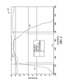
- the band reject structure 130 in combination with the rejection of light provided by the first and second windows 120 , 125 provide notch filters about 2.7 ⁇ m and 4.4 ⁇ m as illustrated in a transmission versus wavelength graph 200 in FIG. 2 .
- the wavelength corresponding to 2.7 ⁇ m is shown by line 210
- 4.4 ⁇ m is shown by line 215 .
- the transmission response provided by the first window 120 and detector response is indicated at 220 and the response provided by the second window is indicated at 225 .
- the band reject structure provides a reject notch indicated at 230 between approximately 2.8 to 4.3 ⁇ m.
- the reject notch 230 in combination with the response of the first window at 120 and the detector at 220 , provide a first transmission notch 235 and second transmission notch 240 corresponding to the hydrogen based flame emission of 2.7 ⁇ m and hydrocarbon based flame emission of 4.4 ⁇ m.
- the band rejection structure may be a mirror designed to reflect light in the rejection band.
- the mirror may be supported by an outer surface of the second window 125 .
- the rejection band is between approximately 2.8 ⁇ m and 4.3 ⁇ m.
- the first window 120 rejects light having a wavelength below approximately 2.6 ⁇ m and the second window 125 rejects light having a wavelength above 4.5 ⁇ m.
- the band rejection structure may be a dual notch filter designed to pass light about 2.7 ⁇ m and 4.4 ⁇ m.
- the dual notch filter may be formed with multiple layers.
- One example of a multiple layer band rejection structure includes the following layers with corresponding depths in ⁇ ms:
- This multi-layer dual notch filter may be represented by an approximate formula: (HL) ⁇ 5(LH) ⁇ 5(BA) ⁇ 5(AB) ⁇ 5/Al2O3 where
- the band reject structure 130 rejects a portion of light having a wavelength greater than a value from 2.8 to 3.2 ⁇ m and less than 4.3 ⁇ m.
- the band rejection structure 130 is used in conjunction with the first window 120 that is adapted to reject light having a wavelength below approximately 2.6 ⁇ m as illustrated by response 310 corresponding to the first window and detector, and the second window 125 that is adapted to reject light having a wavelength having a value of greater than 4.5 to 4.8 ⁇ m as indicated by response 315 .
- bands of light about 2.7 ⁇ m at 320 and 4.4 ⁇ m at 325 are detected.
- These bands are deliberately shifted toward longer wavelengths to accommodate wavelength shifting of light by system optics from flames at angles different than orthogonal to the detector windows. As light strikes the second window at an angle from normal, the wavelength of the light is slightly decreased.
- the notch filters By first shifting the notch filters toward longer wavelengths, the shift toward shorter wavelengths caused by the system optics is accommodated, and the field of view of the detector 100 is increased. Note that the lower boundaries of the bands are not shifted, as they still are selected to detect flames emitting radiation orthogonal to the windows and detectors.
- FIG. 4 is a graph 400 that illustrates mid band rejection when the band reject structure 130 is a mirror, or a reflection filter.
- the response of the filter is indicated at 410 , with the response of the first window and detector indicated at 415 and that of the second window indicated at 420 .
- a wide band transmission filter 425 is used as part of the band rejection structure 130 .
- the combination of the mirror and wide band transmission filter 425 provides similar notches to pass the desired frequencies. In one embodiment, the notches may be shifted toward longer wavelengths to provide a wider field of view.
- the mirror or rejection filter may be formed with multiple layers arranged as follows:
- the various embodiments of the flame detector may provide the ability to detect flame from multiple different sources, while reducing the amount of false positives resulting from hot bodies that are not on flame.
- the detector may operate over a wide field of view in various embodiments by shifting edges of the notch filters toward longer wavelengths to account for corresponding wavelength shifts caused by radiation entering the detector from an angle. Angles of 30 degrees or more may be accommodated by such shifts.
- a flame detector comprising:
- a flame detector comprising:
- a method comprising:
Abstract
A flame detector includes an infrared detector and a first window covering the infrared detector. A second window is positioned in front of the first window. The flame detector is adapted to reject light having a wavelength below approximately 2 μm and to reject light having a wavelength above approximately 6 μm, allowing detection of flame from multiple sources. In variations, the windows in combination with the infrared detector may provide the rejection or a band pass filter provides the rejection. Still further variations utilize notch filters or a band reject filter to provide notches of light to the infrared detector corresponding to the wavelength of different flame sources to be detected.
Description
Traditional flame detectors use bandpass filters, allowing detection of flames in one infrared optical band by an IR detector. Generally, these filters are built to pass 4.4 μm light corresponding to hydrocarbon based flames, or to pass 2.7 μm light corresponding to hydrogen based flames. A detector will not detect a flame outside the bandwidth that it is designed to pass. Thus, a detector built for a hydrocarbon based flame will not detect a hydrogen based flame.
A flame detector includes an infrared detector and a first window covering the infrared detector. A second window is positioned in front of the first window. The flame detector is adapted to reject light having a wavelength below approximately 2 μm and to reject light having a wavelength above approximately 6 μm, allowing detection of flame from multiple sources. In variations, the windows in combination with the infrared detector may provide the rejection or a band pass filter provides the rejection. Still further variations utilize notch filters or a band reject filter to provide notches of light to the infrared detector corresponding to the wavelength of different flame sources to be detected.
In the following description, reference is made to the accompanying drawings that form a part hereof, and in which is shown by way of illustration specific embodiments which may be practiced. These embodiments are described in sufficient detail to enable those skilled in the art to practice the invention, and it is to be understood that other embodiments may be utilized and that structural, logical and electrical changes may be made without departing from the scope of the present invention. The following description of example embodiments is, therefore, not to be taken in a limited sense, and the scope of the present invention is defined by the appended claims.
The functions or algorithms described herein may be implemented in software or a combination of software and human implemented procedures in one embodiment. The software may consist of computer executable instructions stored on computer readable media such as memory or other type of storage devices. Further, such functions correspond to modules, which are software, hardware, firmware or any combination thereof. Multiple functions may be performed in one or more modules as desired, and the embodiments described are merely examples. The software may be executed on a digital signal processor, ASIC, microprocessor, or other type of processor operating on a computer system, such as a personal computer, server or other computer system.
A block diagram of a flame detector is illustrated at 100 in FIG. 1 . An array of infrared detectors 110 is disposed on a substrate 115. The array is sealed by a first window 120 disposed over the array. The first window 120 is adapted to reject light having a wavelength below approximately 2 μm. The first window may be formed of Ge in one embodiment, and may further reject light having a wavelength below approximately 2.6 μm.
A second window 125 is positioned in front of the first window 120 such that the first and second windows provide a path for light from a flame to impinge on the infrared detectors 110. The second window is adapted to reject light having a wavelength above approximately 6 μm in one embodiment, and above approximately 4.5 μm in a further embodiment. In some embodiments, the second window 125 is formed of sapphire, such as explosion proof sapphire. The second window may be a 12 mm thick Al2O3 window in some embodiments.
In a further embodiment, a filter such as a band reject structure 130 is positioned on one of the first and second windows to reject a portion of light having a wavelength greater than 2.7 μm and less than 4.4 μm. Hot objects can have a significant emission in the 3-5 μm band that can equal the intensity of narrower line emissions from actual flames. The notch filters operate to reject light from hot objects that is not indicative of a flame, yet can cause false readings in prior flame detectors.
The band reject structure 130 in combination with the rejection of light provided by the first and second windows 120, 125 provide notch filters about 2.7 μm and 4.4 μm as illustrated in a transmission versus wavelength graph 200 in FIG. 2 . The wavelength corresponding to 2.7 μm is shown by line 210, and 4.4 μm is shown by line 215. The transmission response provided by the first window 120 and detector response is indicated at 220 and the response provided by the second window is indicated at 225. The band reject structure provides a reject notch indicated at 230 between approximately 2.8 to 4.3 μm. The reject notch 230, in combination with the response of the first window at 120 and the detector at 220, provide a first transmission notch 235 and second transmission notch 240 corresponding to the hydrogen based flame emission of 2.7 μm and hydrocarbon based flame emission of 4.4 μm.
In one embodiment, the band rejection structure may be a mirror designed to reflect light in the rejection band. The mirror may be supported by an outer surface of the second window 125. In one embodiment, the rejection band is between approximately 2.8 μm and 4.3 μm.
In a further embodiment, the first window 120 rejects light having a wavelength below approximately 2.6 μm and the second window 125 rejects light having a wavelength above 4.5 μm.
In a further embodiment, the band rejection structure may be a dual notch filter designed to pass light about 2.7 μm and 4.4 μm. The dual notch filter may be formed with multiple layers. One example of a multiple layer band rejection structure includes the following layers with corresponding depths in μms:
| SI | 188.34 | ||
| ZRO2SIO2 | 318.47 | ||
| SI | 196.88 | ||
| ZRO2SIO2 | 318.52 | ||
| SI | 198.82 | ||
| ZRO2SIO2 | 318.51 | ||
| SI | 194.97 | ||
| ZRO2SIO2 | 318.44 | ||
| SI | 177.22 | ||
| ZRO2SIO2 | 636.58 | ||
| SI | 176.65 | ||
| ZRO2SIO2 | 318.44 | ||
| SI | 195.38 | ||
| ZRO2SIO2 | 318.53 | ||
| SI | 202.01 | ||
| ZRO2SIO2 | 318.55 | ||
| SI | 198.82 | ||
| ZRO2SIO2 | 318.48 | ||
| SI | 188.22 | ||
| SI | 303.77 | ||
| ZRO2SIO2 | 519.07 | ||
| SI | 313.35 | ||
| ZRO2SIO2 | 519.11 | ||
| SI | 315.08 | ||
| ZRO2SIO2 | 519.09 | ||
| SI | 306.69 | ||
| ZRO2SIO2 | 519.03 | ||
| SI | 303.40 | ||
| ZRO2SIO2 | 1038.03 | ||
| SI | 297.01 | ||
| ZRO2SIO2 | 518.91 | ||
| SI | 283.09 | ||
| ZRO2SIO2 | 518.82 | ||
| SI | 278.31 | ||
| ZRO2SIO2 | 518.84 | ||
| SI | 284.26 | ||
| ZRO2SIO2 | 518.91 | ||
| SI | 294.15 | ||
This multi-layer dual notch filter may be represented by an approximate formula:
(HL)^5(LH)^5(BA)^5(AB)^5/Al2O3 where
(HL)^5(LH)^5(BA)^5(AB)^5/Al2O3 where
- H=Si A=1.63H
- L=Sencoe ZrO2 B=1.63L
The filter has the following approximate characteristics:
Transmits 2700 nm and 4400 nm and blocks below 2500 nm and above 6000 nm Reducing layers widens peaks
Optimized for 2 peaks and minimized at 3400-3600 nm
Not much pyro detector response below 2.3 μm
No sapphire transmission above ˜5.0 μm
This is just one example, and the depths of the layers, number of layers, and content of the layers may be varied in further embodiments.
In a further embodiment illustrated in a graph 300 in FIG. 3 , the band reject structure 130 rejects a portion of light having a wavelength greater than a value from 2.8 to 3.2 μm and less than 4.3 μm. The band rejection structure 130 is used in conjunction with the first window 120 that is adapted to reject light having a wavelength below approximately 2.6 μm as illustrated by response 310 corresponding to the first window and detector, and the second window 125 that is adapted to reject light having a wavelength having a value of greater than 4.5 to 4.8 μm as indicated by response 315. In the resulting structure, bands of light about 2.7 μm at 320 and 4.4 μm at 325 are detected. These bands are deliberately shifted toward longer wavelengths to accommodate wavelength shifting of light by system optics from flames at angles different than orthogonal to the detector windows. As light strikes the second window at an angle from normal, the wavelength of the light is slightly decreased. By first shifting the notch filters toward longer wavelengths, the shift toward shorter wavelengths caused by the system optics is accommodated, and the field of view of the detector 100 is increased. Note that the lower boundaries of the bands are not shifted, as they still are selected to detect flames emitting radiation orthogonal to the windows and detectors.
In one embodiment, the mirror or rejection filter may be formed with multiple layers arranged as follows:
| ZRO2 | 307.22 | ||
| SIO2 | 991.51 | ||
| ZRO2 | 307.43 | ||
| SIO2 | 0.00 | ||
| ZRO2 | 797.69 | ||
| SIO2 | 712.82 | ||
| ZRO2 | 413.83 | ||
| SIO2 | 613.02 | ||
| ZRO2 | 413.19 | ||
| SIO2 | 605.66 | ||
| ZRO2 | 403.90 | ||
| SIO2 | 638.60 | ||
| ZRO2 | 400.74 | ||
| SIO2 | 677.17 | ||
| ZRO2 | 461.27 | ||
| SIO2 | 165.51 | ||
| ZRO2 | 575.39 | ||
This is just one example, and the depths of the layers, number of layers, and content of the layers may be varied in further embodiments.
The various embodiments of the flame detector may provide the ability to detect flame from multiple different sources, while reducing the amount of false positives resulting from hot bodies that are not on flame. The detector may operate over a wide field of view in various embodiments by shifting edges of the notch filters toward longer wavelengths to account for corresponding wavelength shifts caused by radiation entering the detector from an angle. Angles of 30 degrees or more may be accommodated by such shifts.
The word, approximately, has been used with respect to various wavelengths. When used to describe wavelengths for the various structures that pass or reflect light, the actual values used may vary about the stated value in a manner that still permits detection of flame at the various wavelengths described. For instance, the shifts of notch filters toward longer wavelengths may vary by several tenths of micrometers, yet still provide for adequate detection of flames at the desired wavelengths. The amount of discrimination of hot bodies may be ignored in some instances, or taken into consideration in others depending on design needs.
1. A flame detector comprising:
- an infrared detector;
- a detector system response able to reject light having a wavelength below approximately 2 μm; and
- a second window positioned in front of the detector system, wherein the second window is adapted to reject light having a wavelength above approximately 6 μm.
2. The flame detector of example 1 and further comprising a first window formed of germanium to reject light having a wavelength below approximately 2 μm.
3. The flame detector of any one of examples 1-2 wherein the second window is formed of sapphire.
4. The flame detector of any one of examples 1-3 wherein the infrared detector is an infrared detector array.
5. The flame detector of any one of examples 1-4 and further comprising a band reject structure to reject a portion of light having a wavelength greater than 2.7 μm and less than 4.4 μm.
6. The flame detector of example 5 and further comprising a first window formed of germanium wherein the band reject structure is supported by the second window or the first window.
7. The flame detector of any one of examples 5-6 wherein the first window rejects light having a wavelength below approximately 2.6 μm and wherein the second window rejects light having a wavelength above 4.5 μm.
8. The flame detector of any one of examples 5-7 and further comprising a band pass filter to pass light having a wavelength greater than approximately 2.6 μm and less than approximately 4.5 μm.
9. The flame detector of any one of examples 1-8 and further comprising a band reject structure to reject a portion of light having a wavelength greater than 2.8 μm and less than 4.3 μm wherein the first window rejects light having a wavelength below approximately 2600 μm and wherein the second window rejects light having a wavelength above 4600 μm such that bands of light about 2.7 μm and 4.4 μm are passed to the detector after accommodating for a shift to shorter wavelengths caused by a field of view of the flame detector.
10. The flame detector of example 9 wherein the flame detector provides a field of view to accommodate shifting of light from flames at angles different than orthogonal to the detector windows.
11. A flame detector comprising:
- an infrared detector;
- a first window covering the infrared detector;
- a second window positioned in front of the first window; and
- a band transmission filter positioned to block light having a wavelength less than approximately 2.5 μm and block light having a wavelength greater than approximately 4.5 μm from reaching the infrared detector.
12. The flame detector of example 11 and further comprising a band reject structure to reject a portion of light having a wavelength greater than 2.8 μm and less than 4.3 μm.
13. The flame detector of example 12 wherein bands of light about 2.7 μm and 4.4 μm are passed to the detector, wherein the bands have already been shifted to shorter wavelengths by optical elements in the flame detector.
14. The flame detector of example 13 wherein the flame detector provides a field of view to accommodate wavelength shifting of light from flames at angles different than orthogonal to the detector windows.
15. The flame detector of any one of examples 11-14 wherein the first window is formed of germanium.
16. The flame detector of any one of examples 11-15 wherein the second window is formed of sapphire.
17. A method comprising:
- receiving light from a potential source of flame;
- rejecting light having a wavelength below approximately 2 μm;
- rejecting light having a wavelength above approximately 6 μm; and
- providing the light not rejected to an infrared detector element.
18. The method of example 17 wherein the light is rejected by a bandpass filter.
19. The method of any one of examples 17-18 and further comprising rejecting light between approximately 2.8 μm and 4.3 μm.
20. The method of any one of examples 11-19 wherein the light is rejected by a first window covering the infrared detector element and a second window positioned over the first window.
Although a few embodiments have been described in detail above, other modifications are possible. For example, the logic flows depicted in the figures do not require the particular order shown, or sequential order, to achieve desirable results. Other steps may be provided, or steps may be eliminated, from the described flows, and other components may be added to, or removed from, the described systems. Other embodiments may be within the scope of the following claims.
Claims (13)
1. A flame detector comprising:
an infrared detector;
a first window formed of germanium positioned adjacent the infrared detector, wherein the first window rejects light having a wavelength below approximately 2.6 μm;
a second window positioned adjacent to the first window, wherein the second window rejects light having a wavelength above approximately 4.5 μm; and
a band reject structure positioned adjacent to the second window, wherein the band reject structure rejects a portion of light having a wavelength greater than 2.7 μm and less than 4.4 μm.
2. The flame detector of claim 1 wherein the second window is formed of sapphire.
3. The flame detector of claim 1 wherein the infrared detector is an infrared detector array.
4. The flame detector of claim 1 wherein the band reject structure is supported by the second window or the first window.
5. The flame detector of claim 1 and further comprising a band pass filter to pass light having a wavelength greater than approximately 2.6 μm and less than approximately 4.5 μm.
6. A flame detector comprising:
an infrared detector;
a first window covering the infrared detector;
a second window positioned in front of the first window;
a band transmission filter positioned to block light having a wavelength less than approximately 2.5 μm and block light having a wavelength greater than approximately 4.5 μm from reaching the infrared detector, thereby permitting transmission of light having a wavelength of between 2.5 μm and 4.5 μm; and
a band reject structure positioned to reject light having a wavelength greater than 2.8 μm and less than 4.3 μm, such that light between 2.5 μm and 2.8 μm and light between 4.3 μm and 4.5 μm is transmitted to the infrared detector.
7. The flame detector of claim 6 wherein bands of light about 2.7 μm and 4.4 μm are passed to the infrared detector, wherein the bands have already been shifted to shorter wavelengths by optical elements in the flame detector.
8. The flame detector of claim 7 wherein the flame detector provides a field of view to accommodate wavelength shifting of light from flames at angles different than orthogonal to the detector windows.
9. The flame detector of claim 6 wherein the first window is formed of germanium.
10. The flame detector of claim 6 wherein the second window is formed of sapphire.
11. A method comprising:
receiving light from a potential source of flame;
rejecting light having a wavelength below approximately 2.7 μm;
rejecting light having a wavelength above approximately 4.4 μm;
rejecting light between approximately 2.8 μm and 4.3 μm; and
providing light having a wavelength of between 2.7-2.8 μm or light having a wavelength of between 4.3-4.4 μm to an infrared detector element.
12. The method of claim 11 wherein the light is rejected by a bandpass filter.
13. The method of claim 11 wherein the light is rejected by a first window covering the infrared detector element and a second window positioned over the first window.
Priority Applications (2)
| Application Number | Priority Date | Filing Date | Title |
|---|---|---|---|
| US13/417,644 US9587987B2 (en) | 2012-03-12 | 2012-03-12 | Method and device for detection of multiple flame types |
| EP13157513.6A EP2639778B1 (en) | 2012-03-12 | 2013-03-01 | Method and device for detection of multiple flame types |
Applications Claiming Priority (1)
| Application Number | Priority Date | Filing Date | Title |
|---|---|---|---|
| US13/417,644 US9587987B2 (en) | 2012-03-12 | 2012-03-12 | Method and device for detection of multiple flame types |
Publications (2)
| Publication Number | Publication Date |
|---|---|
| US20130234028A1 US20130234028A1 (en) | 2013-09-12 |
| US9587987B2 true US9587987B2 (en) | 2017-03-07 |
Family
ID=47826966
Family Applications (1)
| Application Number | Title | Priority Date | Filing Date |
|---|---|---|---|
| US13/417,644 Active 2034-07-29 US9587987B2 (en) | 2012-03-12 | 2012-03-12 | Method and device for detection of multiple flame types |
Country Status (2)
| Country | Link |
|---|---|
| US (1) | US9587987B2 (en) |
| EP (1) | EP2639778B1 (en) |
Cited By (2)
| Publication number | Priority date | Publication date | Assignee | Title |
|---|---|---|---|---|
| US10345152B2 (en) * | 2015-10-19 | 2019-07-09 | Ffe Limited | Flame detectors and associated methods |
| US11519602B2 (en) | 2019-06-07 | 2022-12-06 | Honeywell International Inc. | Processes and systems for analyzing images of a flare burner |
Families Citing this family (1)
| Publication number | Priority date | Publication date | Assignee | Title |
|---|---|---|---|---|
| US10690057B2 (en) | 2017-04-25 | 2020-06-23 | General Electric Company | Turbomachine combustor end cover assembly with flame detector sight tube collinear with a tube of a bundled tube fuel nozzle |
Citations (16)
| Publication number | Priority date | Publication date | Assignee | Title |
|---|---|---|---|---|
| GB2020417A (en) | 1978-04-25 | 1979-11-14 | Cerberus Ag | Flame detecting fire alarm |
| US4206454A (en) * | 1978-05-08 | 1980-06-03 | Chloride Incorporated | Two channel optical flame detector |
| US4459484A (en) * | 1980-12-03 | 1984-07-10 | Cerberus Ag | Radiation detector for a flame alarm |
| US5422484A (en) * | 1989-12-20 | 1995-06-06 | Alenia Spazio Spa | Infrared sensor suitable for fire fighting applications |
| US5557262A (en) | 1995-06-07 | 1996-09-17 | Pittway Corporation | Fire alarm system with different types of sensors and dynamic system parameters |
| US5691703A (en) | 1995-06-07 | 1997-11-25 | Hughes Associates, Inc. | Multi-signature fire detector |
| US5726633A (en) | 1995-09-29 | 1998-03-10 | Pittway Corporation | Apparatus and method for discrimination of fire types |
| GB2335489A (en) | 1998-03-19 | 1999-09-22 | Thorn Security | A radiation detector |
| US6057549A (en) | 1996-07-31 | 2000-05-02 | Fire Sentry Corporation | Fire detector with multi-level response |
| US6064064A (en) | 1996-03-01 | 2000-05-16 | Fire Sentry Corporation | Fire detector |
| EP1174836A2 (en) | 2000-07-21 | 2002-01-23 | Infrared Integrated Systems Ltd. | Multipurpose detector |
| US6515283B1 (en) | 1996-03-01 | 2003-02-04 | Fire Sentry Corporation | Fire detector with modulation index measurement |
| US6518574B1 (en) | 1996-03-01 | 2003-02-11 | Fire Sentry Corporation | Fire detector with multiple sensors |
| US20030102434A1 (en) * | 2001-11-30 | 2003-06-05 | Shunsaku Nakauchi | Flame sensor |
| WO2010151386A1 (en) | 2009-06-24 | 2010-12-29 | Polaris Sensor Technologies, Inc. | Apparatus for flame discrimination utilizing long wavelength pass filters and related method |
| WO2011071011A1 (en) | 2009-12-09 | 2011-06-16 | パナソニック電工株式会社 | Infrared flame detector |
-
2012
- 2012-03-12 US US13/417,644 patent/US9587987B2/en active Active
-
2013
- 2013-03-01 EP EP13157513.6A patent/EP2639778B1/en active Active
Patent Citations (16)
| Publication number | Priority date | Publication date | Assignee | Title |
|---|---|---|---|---|
| GB2020417A (en) | 1978-04-25 | 1979-11-14 | Cerberus Ag | Flame detecting fire alarm |
| US4206454A (en) * | 1978-05-08 | 1980-06-03 | Chloride Incorporated | Two channel optical flame detector |
| US4459484A (en) * | 1980-12-03 | 1984-07-10 | Cerberus Ag | Radiation detector for a flame alarm |
| US5422484A (en) * | 1989-12-20 | 1995-06-06 | Alenia Spazio Spa | Infrared sensor suitable for fire fighting applications |
| US5557262A (en) | 1995-06-07 | 1996-09-17 | Pittway Corporation | Fire alarm system with different types of sensors and dynamic system parameters |
| US5691703A (en) | 1995-06-07 | 1997-11-25 | Hughes Associates, Inc. | Multi-signature fire detector |
| US5726633A (en) | 1995-09-29 | 1998-03-10 | Pittway Corporation | Apparatus and method for discrimination of fire types |
| US6518574B1 (en) | 1996-03-01 | 2003-02-11 | Fire Sentry Corporation | Fire detector with multiple sensors |
| US6064064A (en) | 1996-03-01 | 2000-05-16 | Fire Sentry Corporation | Fire detector |
| US6515283B1 (en) | 1996-03-01 | 2003-02-04 | Fire Sentry Corporation | Fire detector with modulation index measurement |
| US6057549A (en) | 1996-07-31 | 2000-05-02 | Fire Sentry Corporation | Fire detector with multi-level response |
| GB2335489A (en) | 1998-03-19 | 1999-09-22 | Thorn Security | A radiation detector |
| EP1174836A2 (en) | 2000-07-21 | 2002-01-23 | Infrared Integrated Systems Ltd. | Multipurpose detector |
| US20030102434A1 (en) * | 2001-11-30 | 2003-06-05 | Shunsaku Nakauchi | Flame sensor |
| WO2010151386A1 (en) | 2009-06-24 | 2010-12-29 | Polaris Sensor Technologies, Inc. | Apparatus for flame discrimination utilizing long wavelength pass filters and related method |
| WO2011071011A1 (en) | 2009-12-09 | 2011-06-16 | パナソニック電工株式会社 | Infrared flame detector |
Non-Patent Citations (2)
| Title |
|---|
| "European Application Serial No. 12794105.2, Response filed Feb. 6, 2014 to Examination Notification Art. 94(3) mailed Aug. 2, 2013", 3 pgs. |
| "European Application Serial No. 13157513.6, Examination Notification Art. 94(3) mailed Aug. 2, 2013", 5 pgs. |
Cited By (2)
| Publication number | Priority date | Publication date | Assignee | Title |
|---|---|---|---|---|
| US10345152B2 (en) * | 2015-10-19 | 2019-07-09 | Ffe Limited | Flame detectors and associated methods |
| US11519602B2 (en) | 2019-06-07 | 2022-12-06 | Honeywell International Inc. | Processes and systems for analyzing images of a flare burner |
Also Published As
| Publication number | Publication date |
|---|---|
| EP2639778A1 (en) | 2013-09-18 |
| EP2639778B1 (en) | 2019-05-08 |
| US20130234028A1 (en) | 2013-09-12 |
Similar Documents
| Publication | Publication Date | Title |
|---|---|---|
| TWI770168B (en) | Induced transmission filter | |
| US8841617B2 (en) | Flame detectors and methods of detecting flames | |
| US20190297278A1 (en) | Solid-state imaging element and imaging device | |
| US20180231791A1 (en) | Optical polarizing filter | |
| CN103839952A (en) | Image-sensing apparatus | |
| TWI761639B (en) | Multispectral sensor response balancing | |
| KR102299714B1 (en) | Image sensor including color filter isolation layer and method of fabricating the same | |
| US9587987B2 (en) | Method and device for detection of multiple flame types | |
| TW201928410A (en) | Optical filters | |
| US20230012033A1 (en) | Multi-bandpass optical interference filter | |
| US10989848B2 (en) | Heat-blocking filter and monitoring system | |
| US20210297638A1 (en) | Image-capturing apparatus and image-capturing system | |
| CN109923445B (en) | Optical filter with complementary angular blocking regions | |
| US20230296817A1 (en) | Multi-transmission optical filter | |
| US9166081B2 (en) | Optical sensor | |
| US20170142351A1 (en) | Dual band filters and detectors | |
| WO2017204331A1 (en) | Photosensor | |
| CN205092256U (en) | Silicon avalanche photodiode subassembly | |
| JP2018155645A (en) | Spectral filter unit and spectrophotometric device | |
| KR20240036482A (en) | Optical interference filter |
Legal Events
| Date | Code | Title | Description |
|---|---|---|---|
| AS | Assignment |
Owner name: HONEYWELL INTERNATIONAL INC., NEW JERSEY Free format text: ASSIGNMENT OF ASSIGNORS INTEREST;ASSIGNORS:LARSEN, CHRISTOPHER SCOTT;COLE, BARRETT E.;REEL/FRAME:027844/0116 Effective date: 20120309 |
|
| STCF | Information on status: patent grant |
Free format text: PATENTED CASE |
|
| MAFP | Maintenance fee payment |
Free format text: PAYMENT OF MAINTENANCE FEE, 4TH YEAR, LARGE ENTITY (ORIGINAL EVENT CODE: M1551); ENTITY STATUS OF PATENT OWNER: LARGE ENTITY Year of fee payment: 4 |