US9581751B2 - Optical waveguide and lamp including same - Google Patents
Optical waveguide and lamp including same Download PDFInfo
- Publication number
- US9581751B2 US9581751B2 US13/839,949 US201313839949A US9581751B2 US 9581751 B2 US9581751 B2 US 9581751B2 US 201313839949 A US201313839949 A US 201313839949A US 9581751 B2 US9581751 B2 US 9581751B2
- Authority
- US
- United States
- Prior art keywords
- optical waveguide
- extraction
- waveguide
- light
- extraction features
- Prior art date
- Legal status (The legal status is an assumption and is not a legal conclusion. Google has not performed a legal analysis and makes no representation as to the accuracy of the status listed.)
- Active, expires
Links
- 230000003287 optical effect Effects 0.000 title claims abstract description 114
- 238000000605 extraction Methods 0.000 claims abstract description 168
- 239000000463 material Substances 0.000 claims abstract description 61
- 230000008878 coupling Effects 0.000 claims description 34
- 238000010168 coupling process Methods 0.000 claims description 34
- 238000005859 coupling reaction Methods 0.000 claims description 34
- NIXOWILDQLNWCW-UHFFFAOYSA-N acrylic acid group Chemical group C(C=C)(=O)O NIXOWILDQLNWCW-UHFFFAOYSA-N 0.000 claims description 7
- 229920000515 polycarbonate Polymers 0.000 claims description 6
- 239000004417 polycarbonate Substances 0.000 claims description 6
- 229920001296 polysiloxane Polymers 0.000 claims description 6
- 229910052751 metal Inorganic materials 0.000 claims description 5
- 239000002184 metal Substances 0.000 claims description 5
- 239000011521 glass Substances 0.000 claims description 3
- 229920001343 polytetrafluoroethylene Polymers 0.000 claims description 3
- 239000004810 polytetrafluoroethylene Substances 0.000 claims description 3
- 230000001154 acute effect Effects 0.000 claims description 2
- -1 polytetrafluoroethylene Polymers 0.000 claims description 2
- DHKHKXVYLBGOIT-UHFFFAOYSA-N 1,1-Diethoxyethane Chemical compound CCOC(C)OCC DHKHKXVYLBGOIT-UHFFFAOYSA-N 0.000 claims 1
- 239000011354 acetal resin Substances 0.000 claims 1
- 229920006324 polyoxymethylene Polymers 0.000 claims 1
- 238000009826 distribution Methods 0.000 description 15
- 238000005286 illumination Methods 0.000 description 9
- 239000000758 substrate Substances 0.000 description 8
- 239000000853 adhesive Substances 0.000 description 5
- 230000001070 adhesive effect Effects 0.000 description 5
- 230000008901 benefit Effects 0.000 description 5
- 238000013461 design Methods 0.000 description 5
- 239000004020 conductor Substances 0.000 description 4
- 230000007704 transition Effects 0.000 description 4
- 239000003990 capacitor Substances 0.000 description 3
- 239000013256 coordination polymer Substances 0.000 description 3
- 238000000034 method Methods 0.000 description 3
- 230000000717 retained effect Effects 0.000 description 3
- 230000002411 adverse Effects 0.000 description 2
- 229910052782 aluminium Inorganic materials 0.000 description 2
- XAGFODPZIPBFFR-UHFFFAOYSA-N aluminium Chemical compound [Al] XAGFODPZIPBFFR-UHFFFAOYSA-N 0.000 description 2
- 230000008859 change Effects 0.000 description 2
- 239000011248 coating agent Substances 0.000 description 2
- 238000000576 coating method Methods 0.000 description 2
- 238000011161 development Methods 0.000 description 2
- 238000010586 diagram Methods 0.000 description 2
- 230000000694 effects Effects 0.000 description 2
- 230000004313 glare Effects 0.000 description 2
- 238000007689 inspection Methods 0.000 description 2
- 238000009434 installation Methods 0.000 description 2
- 230000003278 mimic effect Effects 0.000 description 2
- 238000012546 transfer Methods 0.000 description 2
- 238000003466 welding Methods 0.000 description 2
- 229920004943 Delrin® Polymers 0.000 description 1
- 241000209035 Ilex Species 0.000 description 1
- OAICVXFJPJFONN-UHFFFAOYSA-N Phosphorus Chemical compound [P] OAICVXFJPJFONN-UHFFFAOYSA-N 0.000 description 1
- 125000000218 acetic acid group Chemical group C(C)(=O)* 0.000 description 1
- 239000008186 active pharmaceutical agent Substances 0.000 description 1
- 238000003491 array Methods 0.000 description 1
- 239000003795 chemical substances by application Substances 0.000 description 1
- 230000001143 conditioned effect Effects 0.000 description 1
- 230000001419 dependent effect Effects 0.000 description 1
- 238000005516 engineering process Methods 0.000 description 1
- 239000000835 fiber Substances 0.000 description 1
- 230000004907 flux Effects 0.000 description 1
- 229910052736 halogen Inorganic materials 0.000 description 1
- 150000002367 halogens Chemical class 0.000 description 1
- 239000000203 mixture Substances 0.000 description 1
- 238000012986 modification Methods 0.000 description 1
- 230000004048 modification Effects 0.000 description 1
- 230000009467 reduction Effects 0.000 description 1
- 238000011160 research Methods 0.000 description 1
- 239000011347 resin Substances 0.000 description 1
- 229920005989 resin Polymers 0.000 description 1
- 230000004044 response Effects 0.000 description 1
- 238000007493 shaping process Methods 0.000 description 1
- 229910052709 silver Inorganic materials 0.000 description 1
- 239000004332 silver Substances 0.000 description 1
- 238000009827 uniform distribution Methods 0.000 description 1
- 238000005019 vapor deposition process Methods 0.000 description 1
- 230000000007 visual effect Effects 0.000 description 1
- 238000005406 washing Methods 0.000 description 1
Images


Classifications
-
- G—PHYSICS
- G02—OPTICS
- G02B—OPTICAL ELEMENTS, SYSTEMS OR APPARATUS
- G02B6/00—Light guides; Structural details of arrangements comprising light guides and other optical elements, e.g. couplings
- G02B6/0001—Light guides; Structural details of arrangements comprising light guides and other optical elements, e.g. couplings specially adapted for lighting devices or systems
- G02B6/0011—Light guides; Structural details of arrangements comprising light guides and other optical elements, e.g. couplings specially adapted for lighting devices or systems the light guides being planar or of plate-like form
- G02B6/0033—Means for improving the coupling-out of light from the light guide
- G02B6/0035—Means for improving the coupling-out of light from the light guide provided on the surface of the light guide or in the bulk of it
- G02B6/0045—Means for improving the coupling-out of light from the light guide provided on the surface of the light guide or in the bulk of it by shaping at least a portion of the light guide
- G02B6/0046—Tapered light guide, e.g. wedge-shaped light guide
-
- F—MECHANICAL ENGINEERING; LIGHTING; HEATING; WEAPONS; BLASTING
- F21—LIGHTING
- F21K—NON-ELECTRIC LIGHT SOURCES USING LUMINESCENCE; LIGHT SOURCES USING ELECTROCHEMILUMINESCENCE; LIGHT SOURCES USING CHARGES OF COMBUSTIBLE MATERIAL; LIGHT SOURCES USING SEMICONDUCTOR DEVICES AS LIGHT-GENERATING ELEMENTS; LIGHT SOURCES NOT OTHERWISE PROVIDED FOR
- F21K9/00—Light sources using semiconductor devices as light-generating elements, e.g. using light-emitting diodes [LED] or lasers
- F21K9/20—Light sources comprising attachment means
- F21K9/23—Retrofit light sources for lighting devices with a single fitting for each light source, e.g. for substitution of incandescent lamps with bayonet or threaded fittings
-
- F—MECHANICAL ENGINEERING; LIGHTING; HEATING; WEAPONS; BLASTING
- F21—LIGHTING
- F21K—NON-ELECTRIC LIGHT SOURCES USING LUMINESCENCE; LIGHT SOURCES USING ELECTROCHEMILUMINESCENCE; LIGHT SOURCES USING CHARGES OF COMBUSTIBLE MATERIAL; LIGHT SOURCES USING SEMICONDUCTOR DEVICES AS LIGHT-GENERATING ELEMENTS; LIGHT SOURCES NOT OTHERWISE PROVIDED FOR
- F21K9/00—Light sources using semiconductor devices as light-generating elements, e.g. using light-emitting diodes [LED] or lasers
- F21K9/60—Optical arrangements integrated in the light source, e.g. for improving the colour rendering index or the light extraction
- F21K9/61—Optical arrangements integrated in the light source, e.g. for improving the colour rendering index or the light extraction using light guides
-
- G—PHYSICS
- G02—OPTICS
- G02B—OPTICAL ELEMENTS, SYSTEMS OR APPARATUS
- G02B6/00—Light guides; Structural details of arrangements comprising light guides and other optical elements, e.g. couplings
- G02B6/0001—Light guides; Structural details of arrangements comprising light guides and other optical elements, e.g. couplings specially adapted for lighting devices or systems
- G02B6/0011—Light guides; Structural details of arrangements comprising light guides and other optical elements, e.g. couplings specially adapted for lighting devices or systems the light guides being planar or of plate-like form
- G02B6/0013—Means for improving the coupling-in of light from the light source into the light guide
- G02B6/0015—Means for improving the coupling-in of light from the light source into the light guide provided on the surface of the light guide or in the bulk of it
- G02B6/002—Means for improving the coupling-in of light from the light source into the light guide provided on the surface of the light guide or in the bulk of it by shaping at least a portion of the light guide, e.g. with collimating, focussing or diverging surfaces
- G02B6/0021—Means for improving the coupling-in of light from the light source into the light guide provided on the surface of the light guide or in the bulk of it by shaping at least a portion of the light guide, e.g. with collimating, focussing or diverging surfaces for housing at least a part of the light source, e.g. by forming holes or recesses
-
- G—PHYSICS
- G02—OPTICS
- G02B—OPTICAL ELEMENTS, SYSTEMS OR APPARATUS
- G02B6/00—Light guides; Structural details of arrangements comprising light guides and other optical elements, e.g. couplings
- G02B6/0001—Light guides; Structural details of arrangements comprising light guides and other optical elements, e.g. couplings specially adapted for lighting devices or systems
- G02B6/0011—Light guides; Structural details of arrangements comprising light guides and other optical elements, e.g. couplings specially adapted for lighting devices or systems the light guides being planar or of plate-like form
- G02B6/0013—Means for improving the coupling-in of light from the light source into the light guide
- G02B6/0023—Means for improving the coupling-in of light from the light source into the light guide provided by one optical element, or plurality thereof, placed between the light guide and the light source, or around the light source
- G02B6/0028—Light guide, e.g. taper
-
- G—PHYSICS
- G02—OPTICS
- G02B—OPTICAL ELEMENTS, SYSTEMS OR APPARATUS
- G02B6/00—Light guides; Structural details of arrangements comprising light guides and other optical elements, e.g. couplings
- G02B6/0001—Light guides; Structural details of arrangements comprising light guides and other optical elements, e.g. couplings specially adapted for lighting devices or systems
- G02B6/0011—Light guides; Structural details of arrangements comprising light guides and other optical elements, e.g. couplings specially adapted for lighting devices or systems the light guides being planar or of plate-like form
- G02B6/0013—Means for improving the coupling-in of light from the light source into the light guide
- G02B6/0023—Means for improving the coupling-in of light from the light source into the light guide provided by one optical element, or plurality thereof, placed between the light guide and the light source, or around the light source
- G02B6/0031—Reflecting element, sheet or layer
-
- G—PHYSICS
- G02—OPTICS
- G02B—OPTICAL ELEMENTS, SYSTEMS OR APPARATUS
- G02B6/00—Light guides; Structural details of arrangements comprising light guides and other optical elements, e.g. couplings
- G02B6/0001—Light guides; Structural details of arrangements comprising light guides and other optical elements, e.g. couplings specially adapted for lighting devices or systems
- G02B6/0011—Light guides; Structural details of arrangements comprising light guides and other optical elements, e.g. couplings specially adapted for lighting devices or systems the light guides being planar or of plate-like form
- G02B6/0033—Means for improving the coupling-out of light from the light guide
- G02B6/0035—Means for improving the coupling-out of light from the light guide provided on the surface of the light guide or in the bulk of it
- G02B6/0036—2-D arrangement of prisms, protrusions, indentations or roughened surfaces
-
- G—PHYSICS
- G02—OPTICS
- G02B—OPTICAL ELEMENTS, SYSTEMS OR APPARATUS
- G02B6/00—Light guides; Structural details of arrangements comprising light guides and other optical elements, e.g. couplings
- G02B6/0001—Light guides; Structural details of arrangements comprising light guides and other optical elements, e.g. couplings specially adapted for lighting devices or systems
- G02B6/0011—Light guides; Structural details of arrangements comprising light guides and other optical elements, e.g. couplings specially adapted for lighting devices or systems the light guides being planar or of plate-like form
- G02B6/0033—Means for improving the coupling-out of light from the light guide
- G02B6/0035—Means for improving the coupling-out of light from the light guide provided on the surface of the light guide or in the bulk of it
- G02B6/0038—Linear indentations or grooves, e.g. arc-shaped grooves or meandering grooves, extending over the full length or width of the light guide
-
- G—PHYSICS
- G02—OPTICS
- G02B—OPTICAL ELEMENTS, SYSTEMS OR APPARATUS
- G02B6/00—Light guides; Structural details of arrangements comprising light guides and other optical elements, e.g. couplings
- G02B6/0001—Light guides; Structural details of arrangements comprising light guides and other optical elements, e.g. couplings specially adapted for lighting devices or systems
- G02B6/0011—Light guides; Structural details of arrangements comprising light guides and other optical elements, e.g. couplings specially adapted for lighting devices or systems the light guides being planar or of plate-like form
- G02B6/0033—Means for improving the coupling-out of light from the light guide
- G02B6/0035—Means for improving the coupling-out of light from the light guide provided on the surface of the light guide or in the bulk of it
- G02B6/004—Scattering dots or dot-like elements, e.g. microbeads, scattering particles, nanoparticles
- G02B6/0041—Scattering dots or dot-like elements, e.g. microbeads, scattering particles, nanoparticles provided in the bulk of the light guide
-
- G—PHYSICS
- G02—OPTICS
- G02B—OPTICAL ELEMENTS, SYSTEMS OR APPARATUS
- G02B6/00—Light guides; Structural details of arrangements comprising light guides and other optical elements, e.g. couplings
- G02B6/0001—Light guides; Structural details of arrangements comprising light guides and other optical elements, e.g. couplings specially adapted for lighting devices or systems
- G02B6/0011—Light guides; Structural details of arrangements comprising light guides and other optical elements, e.g. couplings specially adapted for lighting devices or systems the light guides being planar or of plate-like form
- G02B6/0033—Means for improving the coupling-out of light from the light guide
- G02B6/0035—Means for improving the coupling-out of light from the light guide provided on the surface of the light guide or in the bulk of it
- G02B6/004—Scattering dots or dot-like elements, e.g. microbeads, scattering particles, nanoparticles
- G02B6/0043—Scattering dots or dot-like elements, e.g. microbeads, scattering particles, nanoparticles provided on the surface of the light guide
-
- G—PHYSICS
- G02—OPTICS
- G02B—OPTICAL ELEMENTS, SYSTEMS OR APPARATUS
- G02B6/00—Light guides; Structural details of arrangements comprising light guides and other optical elements, e.g. couplings
- G02B6/0001—Light guides; Structural details of arrangements comprising light guides and other optical elements, e.g. couplings specially adapted for lighting devices or systems
- G02B6/0011—Light guides; Structural details of arrangements comprising light guides and other optical elements, e.g. couplings specially adapted for lighting devices or systems the light guides being planar or of plate-like form
- G02B6/0033—Means for improving the coupling-out of light from the light guide
- G02B6/0058—Means for improving the coupling-out of light from the light guide varying in density, size, shape or depth along the light guide
- G02B6/0061—Means for improving the coupling-out of light from the light guide varying in density, size, shape or depth along the light guide to provide homogeneous light output intensity
-
- G—PHYSICS
- G02—OPTICS
- G02B—OPTICAL ELEMENTS, SYSTEMS OR APPARATUS
- G02B6/00—Light guides; Structural details of arrangements comprising light guides and other optical elements, e.g. couplings
- G02B6/0001—Light guides; Structural details of arrangements comprising light guides and other optical elements, e.g. couplings specially adapted for lighting devices or systems
- G02B6/0011—Light guides; Structural details of arrangements comprising light guides and other optical elements, e.g. couplings specially adapted for lighting devices or systems the light guides being planar or of plate-like form
- G02B6/0081—Mechanical or electrical aspects of the light guide and light source in the lighting device peculiar to the adaptation to planar light guides, e.g. concerning packaging
- G02B6/0086—Positioning aspects
- G02B6/009—Positioning aspects of the light source in the package
-
- F—MECHANICAL ENGINEERING; LIGHTING; HEATING; WEAPONS; BLASTING
- F21—LIGHTING
- F21Y—INDEXING SCHEME ASSOCIATED WITH SUBCLASSES F21K, F21L, F21S and F21V, RELATING TO THE FORM OR THE KIND OF THE LIGHT SOURCES OR OF THE COLOUR OF THE LIGHT EMITTED
- F21Y2101/00—Point-like light sources
-
- F—MECHANICAL ENGINEERING; LIGHTING; HEATING; WEAPONS; BLASTING
- F21—LIGHTING
- F21Y—INDEXING SCHEME ASSOCIATED WITH SUBCLASSES F21K, F21L, F21S and F21V, RELATING TO THE FORM OR THE KIND OF THE LIGHT SOURCES OR OF THE COLOUR OF THE LIGHT EMITTED
- F21Y2115/00—Light-generating elements of semiconductor light sources
- F21Y2115/10—Light-emitting diodes [LED]
-
- G—PHYSICS
- G02—OPTICS
- G02B—OPTICAL ELEMENTS, SYSTEMS OR APPARATUS
- G02B6/00—Light guides; Structural details of arrangements comprising light guides and other optical elements, e.g. couplings
- G02B6/0001—Light guides; Structural details of arrangements comprising light guides and other optical elements, e.g. couplings specially adapted for lighting devices or systems
- G02B6/0011—Light guides; Structural details of arrangements comprising light guides and other optical elements, e.g. couplings specially adapted for lighting devices or systems the light guides being planar or of plate-like form
- G02B6/0081—Mechanical or electrical aspects of the light guide and light source in the lighting device peculiar to the adaptation to planar light guides, e.g. concerning packaging
- G02B6/0086—Positioning aspects
- G02B6/0088—Positioning aspects of the light guide or other optical sheets in the package
Definitions
- the present inventive subject matter relates to optical waveguides, and more particularly to optical waveguides for general lighting.
- An optical waveguide mixes and directs light emitted by one or more light sources, such as one or more light emitting diodes (LEDs).
- a typical optical waveguide includes three main components: one or more coupling elements, one or more distribution elements, and one or more extraction elements.
- the coupling component(s) direct light into the distribution element(s), and condition the light to interact with the subsequent components.
- the one or more distribution elements control how light flows through the waveguide and is dependent on the waveguide geometry and material.
- the extraction element(s) determine how light is removed by controlling where and in what direction the light exits the waveguide.
- the primary considerations are: maximizing the efficiency of light transfer from the source into the waveguide; controlling the location of light injected into the waveguide; and controlling the angular distribution of the light in the coupling optic.
- One way of controlling the spatial and angular spread of injected light is by fitting each source with a dedicated lens. These lenses can be disposed with an air gap between the lens and the coupling optic, or may be manufactured from the same piece of material which defines the waveguide's distribution element(s).
- Discrete coupling optics allow numerous advantages such as higher efficiency coupling, controlled overlap of light flux from the sources, and angular control of how the injected light interacts with the remaining elements of the waveguide.
- Discrete coupling optics use refraction, total internal reflection, and surface or volume scattering to control the distribution of light injected into the waveguide.
- the simplest example is a fiber-optic cable, which is designed to transport light from one end of the cable to another with minimal loss in between. To achieve this, fiber optic cables are only gradually curved and sharp bends in the waveguide are avoided. In accordance with well-known principles of total internal reflectance light traveling through a waveguide is reflected back into the waveguide from an outer surface thereof, provided that the incident light does not exceed a critical angle with respect to the surface.
- the light In order for an extraction element to remove light from the waveguide, the light must first contact the feature comprising the element.
- the waveguide surfaces By appropriately shaping the waveguide surfaces, one can control the flow of light across the extraction feature(s). Specifically, selecting the spacing, shape, and other characteristic(s) of the extraction features affects the appearance of the waveguide, its resulting distribution, and efficiency.
- Hulse U.S. Pat. No. 5,812,714 discloses a waveguide bend element configured to change a direction of travel of light from a first direction to a second direction.
- the waveguide bend element includes a collector element that collects light emitted from a light source and directs the light into an input face of the waveguide bend element.
- Light entering the bend element is reflected internally along an outer surface and exits the element at an output face.
- the outer surface comprises beveled angular surfaces or a curved surface oriented such that most of the light entering the bend element is internally reflected until the light reaches the output face
- a light emitting panel assembly that comprises a transparent light emitting panel having a light input surface, a light transition area, and one or more light sources.
- Light sources are preferably embedded or bonded in the light transition area to eliminate any air gaps, thus reducing light loss and maximizing the emitted light.
- the light transition area may include reflective and/or refractive surfaces around and behind each light source to reflect and/or refract and focus the light more efficiently through the light transition area into the light input surface of the light emitting panel.
- a pattern of light extracting deformities may be provided on one or both sides of the panel members.
- a variable pattern of deformities may break up the light rays such that the internal angle of reflection of a portion of the light rays will be great enough to cause the light rays either to be emitted out of the panel or reflected back through the panel and emitted out of the other side.
- Simon U.S. Pat. No. 5,897,201 discloses various embodiments of architectural lighting that is distributed from contained radially collimated light.
- a quasi-point source develops light that is collimated in a radially outward direction and exit means of distribution optics direct the collimated light out of the optics.
- an optical waveguide includes a body of optically transmissive material having a width substantially greater than an overall thickness thereof and including a first side, a second side opposite the first side, a central bore extending between the first and second sides and adapted to receive a light emitting diode, and extraction features on the second side.
- a light diverter extends into the central bore for diverting light into and generally along the width of the body of material.
- the extraction features direct light out of the first side and at least one extraction feature has an extraction surface dimension transverse to the thickness that is between about 5% and about 75% of the overall thickness of the body of material.
- FIG. 1 is an isometric view of a first end of a first lamp incorporating a waveguide according to a first embodiment of the present invention
- FIG. 2 is a first end elevational view of the lamp of FIG. 1 ;
- FIG. 3 is a side devotional view of the lamp of FIG. 1 ;
- FIG. 4 is an isometric view of a second end of the lamp of FIG. 1 ;
- FIG. 5 is a second end elevational view of the lamp of FIG. 1 ;
- FIG. 6 is an exploded isometric first end view of the lamp of FIG. 1 ;
- FIG. 7 is an exploded isometric second end view of the lamp of FIG. 1 ;
- FIG. 8 is a sectional isometric view of the lamp of FIG. 1 ;
- FIG. 9 is an interior isometric view of the waveguide of FIG. 1 ;
- FIG. 10 is an interior elevational view of the waveguide of FIG. 1 ;
- FIG. 11 is a cross sectional view of the waveguide of FIG. 1 taken generally along the lines 11 - 11 of FIG. 10 ;
- FIG. 11A is a view identical to FIG. 11 identifying sample dimensions of the waveguide of FIG. 1 ;
- FIGS. 11B and 11C are isometric views of non-circular and asymmetric waveguides, respectively;
- FIG. 11D is a diagrammatic elevational view of an asymmetric waveguide
- FIGS. 11E and 11F are cross sectional views taken generally along the lines 11 E- 11 E and 11 F- 11 F, respectively, of FIG. 11D ;
- FIG. 12 is an isometric view of a first end of a second lamp incorporating a waveguide according to a second embodiment of the present invention.
- FIG. 13 is a first end elevational view of the lamp of FIG. 12 ;
- FIG. 14 is a first side elevational view of the lamp of FIG. 12 ;
- FIG. 15 is a second side elevational view of the lamp of FIG. 12 ;
- FIG. 16 is a second end isometric view of the lamp of FIG. 12 ;
- FIG. 17 is a second end elevational view of the lamp of FIG. 12 ;
- FIG. 18 is an exploded isometric first end view of the lamp of FIG. 12 ;
- FIGS. 18A and 18B are isometric views of a further lamp
- FIG. 18C is an exploded isometric view of yet another lamp
- FIG. 18D is a side elevational view of the lamp of FIG. 18C as assembled
- FIG. 18E is a front elevational view of the lamp of FIG. 18D ;
- FIG. 18F is a bottom elevational view of the lamp of FIG. 18D ;
- FIG. 18G is a top plan view of the lamp of FIG. 18D ;
- FIGS. 19, 19A and 20-25 are cross sectional views similar to FIG. 11 of further embodiments of waveguides according to the present invention.
- FIGS. 26-29 are elevational views of still further embodiments of waveguides according to the present invention.
- FIG. 30 is a side elevational view, partly in section, of yet another embodiment of a luminaire including a waveguide according to the present invention.
- FIG. 31 is a view identical to FIG. 11 of a further waveguide according to the present invention.
- FIG. 32 is a sectional and first side isometric view of the waveguide of FIG. 31 ;
- FIG. 33 is a sectional and second side isometric view of the waveguide of FIG. 31 ;
- FIG. 34 is a sectional view identical to FIG. 31 identifying sample dimensions of the waveguide thereof;
- FIG. 35 is an enlarged fragmentary view of a portion of the waveguide of FIG. 34 seen generally at the lines 35 - 35 of FIG. 34 ;
- FIGS. 36-38 are isometric, plan and sectional views, respectively, of a further embodiment of an optical waveguide
- FIG. 39 is a schematic diagram of a driver circuit suitable for developing power for the LED(s) of FIGS. 1-8 ;
- FIGS. 40-42 are isometric, plan, and fragmentary sectional views, respectively, of yet another optical waveguide
- FIG. 43 is a side elevational view with portions broken away of a lamp incorporating a waveguide
- FIGS. 44A-44D are a top isometric view, a bottom isometric view, a side elevational view, and a plan view, respectively, of the light assembly of FIG. 43 ;
- FIGS. 45A and 45B are exploded isometric views of the light assembly of FIG. 43 ;
- FIG. 45C is a view similar to FIG. 43 illustrating an alternative lamp incorporating a waveguide.
- a lamp 40 includes a base 42 at which an Edison-style plug 44 is disposed. Extending away from the base 42 is a central body 46 .
- Four arms 48 a - 48 d extend away from the central body 46 .
- a light assembly 50 is disposed on ends of the arms 48 a - 48 d and is secured thereto by any suitable means, such as three screws 51 or other fasteners (shown in FIGS. 5 and 7 ) that extend through holes in the ends of the arms 48 a - 48 c into threaded bores of the light assembly 50 .
- the light assembly 50 includes a base element in the form of a heat exchanger 52 having a central recess 54 defined by a base surface 56 and a tapered circumferential wall 58 .
- the heat exchanger 52 is made of any suitable heat conductive material, such as aluminum, and includes a plurality of heat exchanger fins 59 ( FIGS. 3-7 ) on a side thereof opposite the central recess 54 .
- the base surface 56 and/or the tapered circumferential wall 58 may be covered or coated by a reflective material, which may be a white material or a material that exhibits specular reflective characteristics.
- a light source that may include one or more light emitting diodes (LEDs) 60 (seen in FIG.
- the LED 60 may be a white LED or may comprise multiple LEDs either mounted separately or together on a single substrate or package including a phosphor-coated LED either alone or in combination with a color LED, such as a green LED, etc.
- the light source 60 typically includes a blue shifted yellow LED and a red LED. Different color temperatures and appearances could be produced using other LED combinations, as is known in the art.
- the light source comprises any LED, for example, an MT-G LED incorporating TrueWhite® LED technology as developed and manufactured by Cree, Inc., the assignee of the present application.
- the LED(s) may each have a directional emission distribution (e.g., a side emitting or other distribution or a lambertian distribution), as necessary or desirable.
- the light source 60 is operated by control circuitry 64 in the form of a driver circuit (seen in FIG. 8 ) disposed in the central body 46 that receives AC power via the Edison-style plug.
- the control circuitry 64 may be potted within the central body 46 .
- Wires or conductors extend through one or more of the arms 48 a - 48 d from the control circuitry 64 to the light source 60 .
- wires extend through the arm 48 d into the light assembly 50 .
- a cover 66 ( FIG. 5 ) may be disposed in or over the arm 48 d to provide a passage for the wires.
- the control circuitry 64 is designed to operate the light source 60 with AC or DC power in a desired fashion to produce light of a desired intensity and appearance.
- the heat exchanger 52 is preferably arranged to eliminate thermal crosstalk between the LEDs and the control circuitry.
- the light source 60 develops light appropriate for general illumination purposes including light similar or identical to that provided by an incandescent, halogen, or other lamp that may be incorporated in a down light, a light that produces a wall washing effect, a task light, a troffer, or the like.
- a waveguide 70 has a main body of material 71 ( FIG. 11 ) having a width substantially greater than an overall thickness thereof and is substantially or completely circular in a dimension transverse to the width and thickness ( FIG. 2 ).
- the waveguide 70 is disposed in contact with the base surface 56 and the tapered circumferential wall 58 and is located by four location pins 72 a - 72 d ( FIG. 7 ) that are disposed in corresponding blind bores 74 a - 74 d (only the bores 74 b - 74 d are visible in FIGS. 6 and 8 ).
- the waveguide 70 includes a first or outer side or surface 70 a , a second opposite inner side or surface 70 b , and an interior coupling cavity comprising a central bore 76 that in the illustrated embodiment extends fully through the waveguide 70 from the first side to the second side.
- the walls defining the central bore 76 are normal to the first and second sides 71 a , 71 b of the waveguide 70 and the central bore 76 is coaxial with an outer surface of the main body of material 71 .
- the central bore is preferably polished and optically smooth.
- the light source 60 extends into the central bore 76 from the second side thereof.
- a light diverter of any suitable shape and design such as a conical plug member 78 extends into the central bore 76 from the first side thereof.
- the conical plug member 78 includes a base flange 80 that is secured by any suitable means, such as an adhesive, to an outer surface of the waveguide 70 such that a conical portion 82 extends into the central bore 76 .
- the base flange 80 may be omitted and the outer diameter of the plug member may be slightly greater than the diameter of the bore 76 whereupon the plug member 78 may be press fitted or friction fitted into the bore 76 and/or secured by adhesive or other means.
- the conical plug member 78 may be integral with the waveguide 70 (see FIG. 47 ) rather than being separate therefrom. Further, the light source 60 may be integral with the waveguide 70 , if desired.
- the plug member 78 may be made of white polycarbonate or any other suitable material, such as acrylic, molded silicone, polytetrafluoroethylene (PTFE), Delrin® acetyl resin, or any suitable metal. The material may be coated with reflective silver or other metal or material using any suitable application methodology, such as a vapor deposition process.
- the plug member 78 may be any other suitable shape, including a symmetric or asymmetric shape, as desired.
- the plug member may be non-conical and may have a substantially flat shape, a segmented shape, an inclined shape to direct light out a particular side of the lamp 40 , etc.
- the waveguide 70 may be secured in any suitable fashion and by any suitable means to the heat exchanger 52 .
- a ring member 90 is retained on surfaces of the heat exchanger 52 such that ribs 92 of the heat exchanger 52 are disposed in recesses 94 of the ring member 90 . This securement is accomplished by the screws 51 , which may extend into threaded bosses (not shown) carried on an inner surface of the ring member 90 .
- the ring member 90 bears against that outer surface of the waveguide 70 so that the waveguide 70 is secured in place.
- the lamp 40 has a size and outer envelope equivalent to a PAR 38 lamp, and can be used in any luminaire that can accommodate same. It should be noted that the lamp 40 could be made larger or smaller to fit inside other luminaries and/or to satisfy particular lighting requirements.
- a luminaire with which the lamp 40 could be used is a downlight mounted, for example, in a ceiling.
- the plug 44 of the lamp 40 is screwed into an Edison-style socket in the luminaire such that the light source 60 points downwardly (i.e., the lamp 40 is oriented opposite to the orientation of FIG. 3 such that the plug 44 is above the waveguide 70 .)
- FIG. 11 illustrates the waveguide 70 in such orientation with the light source 60 disposed above the plug member 78 .
- the conical portion 82 is made of or the surface is coated with a white or specular material that is highly reflective such that the great majority of light incident thereon (preferably, although not necessarily, greater than 95%) is reflected into the waveguide 70 in a generally transverse direction along the width of the body of material 71 . Examples of such reflected light rays are shown in FIG. 11 .
- the plug member 78 may be partially or fully transparent or translucent, as desired, to allow at least some light to be transmitted therethrough (for example, at least about 5% of the light may be transmitted through the plug member 78 ).
- the spacing, number, size and geometry of extraction features 100 determine the mixing and distribution of light in the waveguide 70 and light exiting the waveguide 70 .
- the extraction features 100 comprise a series of ridges separated by intervening troughs at least some of which define one or more inverted V-shapes.
- the extraction features 100 are continuous (i.e., they extend fully in a continuous manner about the central bore 76 ), are coaxial with the central bore, and therefore symmetric about the central axis of the central bore 76 .
- the waveguide 70 is tapered from the center of the waveguide to an outside edge in the sense that there is less material at the radially outside edges of the waveguide than at the center.
- Such tapering may be effectuated by providing extraction features that become deeper and/or are more widely separated with distance from the center of the waveguide, as noted in greater detail hereinafter.
- the tapering maximizes the possibility that substantially all the light introduced into the waveguide 70 is extracted over a single pass of the light through the waveguide. This results in substantially all of the light striking the radially outward surfaces of the extraction features 100 , which are carefully controlled so that the extraction of light is also carefully controlled.
- the combination of tapering with the arrangement of extraction features and use of efficient coupling components including the plug member 78 disposed in the bore 76 with the light source 60 together result in improved color mixing with minimum waveguide thickness and excellent control over the emitted light.
- the light emitted out the waveguide 70 is mixed such that point sources of light in the source 60 are not visible to a significant extent and the emitted light is controlled and collimated to a high degree.
- the waveguide is made of optical grade acrylic, polycarbonate, molded silicone, glass, or any other optical grade material and, in one example, has the dimensions noted in the following table and as seen in FIG. 11A . It should be noted that the dimensions in the following table as exemplary only and not limiting (several of the dimensions are taken with respect to a center line 101 ( FIG. 11A ) of the waveguide 70 ):
- Aspect Ratio Width of ridge/Greatest height extent of ridge (I)
- Aspect Ratio Width of ridge/Greatest height extent of ridge (I)
- the waveguide 70 may be designed to create a beam angle that preferably is between less than about 5 degrees to greater than 60 degrees, and more preferably is between about 5 degrees and about 50 degrees and most preferably between about 6 degrees and about 40 degrees.
- the beam peak can either be centered in the nadir (as in a PAR application) or off-center (as in an outdoor application).
- the beam angle and/or peak can be controlled through appropriate design of the waveguide 70 . In the illustrated embodiment of FIG. 11A , the beam angle is about 12 degrees.
- the extraction features may be similar or identical to one another in shape, size, and/or pitch, or may be different from one another in any one or more of these parameters, as desired.
- the extraction features 100 may be other than circular, asymmetric and/or discontinuous.
- FIG. 11B illustrates a racetrack-shaped waveguide 70 a with racetrack-shaped extraction features 100 a
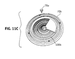
- FIG. 11C shows a circular waveguide 70 b with asymmetric and discontinuous extraction features 100 b
- An asymmetric plug member 78 a that may be used with the waveguide 70 b is illustrated in FIG. 11C .
- Asymmetric extraction features may be used with or without an asymmetric plug member to obtain multiple beam distributions. For example, as seen in FIG.
- a first set of discrete extraction features 100 b disposed in discrete boundaries 100 b - 1 through 100 b - 6 may direct light toward a first direction and at least a second set of extraction features 100 c disposed in discrete boundaries 100 c - 1 through 100 c - 8 may direct light toward at least a second direction with each of the at least two directed beams having substantially identical or different beam widths and/or intensities
- FIGS. 11E and 11F illustrate different extraction features that may accomplish this result.
- the extraction features 100 may comprise a plurality of discrete prisms 102 formed in a lower surface (as seen in FIGS.
- the light source 60 and the plug member 78 extend into a central bore 76 .
- the waveguide main body 103 is disposed on a substrate 104 that may have a reflective coating thereon and light developed by the light source 60 is diverted transversely into the main body 103 and is emitted out a surface 105 by the prisms 102 .
- the prisms may be identical or not identical to one another. Preferably, the prisms face the coupling cavity comprising the central bore 76 .
- FIG. 39 is a schematic diagram of a driver circuit 110 suitable for developing power for the LED(s) and which may be used as the circuitry 64 .
- the driver circuit 110 is an I 2 C control that includes an integrated circuit IC 112 .
- the IC 112 and other circuitry operate as a constant current source.
- the circuit 110 further includes a full-wave rectifier circuit including diodes D 1 -D 4 coupled to a capacitor C 1 and filter elements comprising inductors L 1 and L 2 and a capacitor C 2 .
- a diode D 5 effectuates unidirectional charging of the capacitor C.
- the circuit 110 operates as a two-stage regulation circuit that is capable of operating two sets of LEDs 113 a , 113 b in a controllable dimming fashion in response to a dimming command signal SDA delivered to an input of the IC 112 by a dimmer (not shown).
- each of the LEDs 113 a is capable of developing white light
- each of the LEDs 113 b is capable of producing temperature-compensated red light that adds warmth to the white light developed by the LEDs 113 a .
- the two sets of LEDs 113 a , 113 b may be disposed on a single substrate or may be disposed on multiple substrates, as desired.
- Two transistors Q 1 and Q 2 implement the two stage regulation circuit and are operated together with a third transistor Q 3 to control the current through the LEDs 113 .
- a diode D 6 isolates the transistors Q 1 and Q 2 from one another.
- the IC 112 is also responsive to a signal SCL that is factory set and commands a specific maximum constant current magnitude for the LEDs 113 .
- the IC 112 implements a soft-switching controllable boost and buck converter for dimming of the LED(s) 113 that produces low electromagnetic interference (EMI) and no 120 Hz. AC component in the DC power that is supplied to the LEDs 113 .
- EMI electromagnetic interference
- the balance of the circuit 110 includes a voltage divider including resistors R 1 and R 2 wherein a junction between the resistors R 1 and R 2 is coupled to an input of the IC 112 .
- a thermistor R 3 is disposed in heat transfer relationship with the LEDs 113 b and provides a thermal sensing signal that is fed back to an input of the IC 112 whereby the IC 112 regulates the power delivered to the LEDs 113 b in dependence upon the sensed temperature to effectuate the temperature compensation of the LEDs 113 b .
- a resistor R 4 pulls an input of the IC 112 down when the transistor Q 1 is off and a resistor R 5 couples a Power_In input of the IC 112 to a DC bus 116 .
- the driver circuit 110 is mounted on a single circuit board and is compatible with a wide range of dimmers.
- Any other suitable driver circuit may be used as the circuitry 64 .
- the lamp 140 is intended for use in luminaries that can accommodate PAR 30 bulbs.
- the lamp 140 includes a base 142 at which an Edison-style plug 144 is disposed. Extending away from the base 142 is a cap 145 ( FIG. 18 ) and a central body 146 .
- the cap 145 is secured in any suitable fashion to the central body 146 , such as by ultrasonic welding.
- Four arms 148 a - 148 d extend away from the central body 146 .
- a light assembly 150 is disposed on ends of the arms 148 a - 148 d and is secured thereto by any suitable means, such as four threaded fasteners 151 a - 151 d that extend through associated bores in associated tabs 153 a - 153 d carried by the central body 146 and into threaded bores (not seen in the figures) of the light assembly 150 .
- the light assembly 150 includes a base element in the form of a heat exchanger 152 having a central recess 154 defined by a base surface 156 and a tapered circumferential wall 158 .
- the heat exchanger 152 is made of any suitable heat conductive material, such as aluminum, and includes a plurality of heat exchanger fins 159 on a side thereof opposite the central recess 154 .
- the base surface 156 and/or the tapered circumferential wall 158 may be covered or coated by a reflective material, which may be a white material or a material that exhibits specular reflective characteristics.
- a light source comprising one or more light emitting diodes (LEDs) 160 that is identical or similar to the light source 60 seen in FIG. 8 is mounted on a support member (not seen, but which may be identical or similar to the member 62 described above comprising a heat conductive substrate, such as a metal circuit board), and extends beyond the base surface 156 .
- LEDs light emitting diodes
- the light source 160 is operated by control circuitry (not shown, but which may be identical or similar to the circuitry 64 described above) disposed in the central body 146 that receives AC power via the Edison-style plug.
- control circuitry may be potted in the central body 146 . Wires or conductors extend through one or more of the arms 148 a - 148 d from the control circuitry to the light source 160 .
- the light source 160 develops light appropriate for general illumination purposes.
- a waveguide 170 is disposed in contact with the base surface 156 and the tapered circumferential wall 158 and is located by four location pins 172 that are disposed in corresponding blind bores 174 (the pins and the bores are identical or similar to the pins 72 and bores of FIGS. 6 and 8 ).
- the waveguide 170 is similar or identical to the waveguide 70 or any other waveguide disclosed herein, it being understood that the waveguide may alternatively be modified in accordance with the design details of the present invention.
- the light source 160 extends into a central bore 176 of the waveguide 170 from a second side thereof.
- a conical plug member 178 is secured to the waveguide 170 by any suitable means, such as a press fit, friction fit, and/or adhesive, and extends into the central bore 176 from the first side thereof, as in the embodiment of FIGS. 1-8 .
- the conical plug member 178 may be integral with the waveguide 170 rather than being separate therefrom. (For example, see FIG. 47 , which illustrates that the plug member may be disposed completely within the central bore.)
- the light source 160 may be integral with the waveguide 170 , if desired.
- the waveguide 170 may be secured in any suitable fashion and by any suitable means to the heat exchanger 152 .
- a ring member 190 similar or identical to the ring member 90 is secured to surfaces of the heat exchanger 152 and is retained thereon such that ribs 192 of the heat exchanger 152 are disposed in recesses 194 of the ring member 190 ( FIG. 18 ).
- the ring member 190 bears against that outer surface of the waveguide 170 so that the waveguide 170 is secured in place.
- the lamp 140 can be used for general illumination, such as in a downlight or other luminaire, and achieves the advantages noted with respect to the previous embodiment.
- FIGS. 18A and 18B show yet another lamp 195 suitable for general illumination purposes.
- the lamp 195 may be of a size suitable for use as a PAR 30 lamp.
- the lamp 195 is substantially similar to the lamp 140 and includes two main arms 196 a , 196 b secured to a heat exchanger assembly including open fin structures 197 secured to a lower surface of a light assembly 198 .
- the light assembly 198 includes the waveguide 170 , or any other suitable waveguide, the light source 160 , and the plug member 178 (or any other suitable light source and/or plug assembly).
- the light source 160 is mounted on a circuit board substrate that is intimately thermally coupled to the heat exchanger assembly by one or more rings 198 a .
- Control circuitry (not shown) is disposed within a central body 199 and is connected to control the light source 160 by one or more wires that extend though one or both of the arms 196 a , 196 b .
- the open fin arrangement of the heat exchanger assembly and the intimate thermal coupling of the light source 160 to the heat exchanger assembly may allow improved thermal management such that the lamp 195 might be usable in enclosed installations.
- FIGS. 18C-18G show a still further lamp 195 a suitable for general illumination purposes.
- the lamp 195 a may be of a size suitable for use as a PAR 30 lamp.
- the lamp 195 a is substantially similar to the lamp 140 and includes three main arms 196 c , 196 d , 196 e carried by a cup-shaped member 196 f and secured to a heat exchanger assembly including open fin structures 197 a secured to a lower surface of a light assembly 198 a .
- the light assembly 198 a includes the waveguide 170 , or any other suitable waveguide, the light source 160 , and the plug member 178 (or any other suitable light source and/or plug assembly).
- the light source 160 is mounted on a circuit board substrate that is intimately thermally coupled to the heat exchanger assembly by one or more rings 198 b .
- Control circuitry (not shown) is disposed within a central body 199 a and is connected to control the light source 160 by one or more wires that extend though one or more of the arms 196 c - 196 e .
- the open fin arrangement of the heat exchanger assembly and the intimate thermal coupling of the light source 160 to the heat exchanger assembly may allow improved thermal management such that the lamp 195 a might also be usable in enclosed installations.
- the waveguide can be modified to achieve other visual and/or optical characteristics. Specifically, the size, shape, other geometry, spacing, number, symmetry, and/or other physical characteristic(s) of the waveguide generally and/or the extraction features can be varied, as desired.
- FIG. 19 illustrates a waveguide 202 having an axial outer wall 203 and extraction features 204 comprising a plurality of ridges and troughs 205 , 206 .
- the ridges 205 are unequally spaced, for example, the ridge 205 a is spaced a first distance from an adjacent ridge 205 b , the ridge 205 h is spaced a second, different distance from an adjacent ridge 205 c , and the ridge 205 c is spaced a third distance from an adjacent ridge 205 d .
- the depths of the troughs 206 are different. Specifically, a depth of a trough 206 a is different than the depths of troughs 206 b , 206 c and 206 d .
- the shapes of one or more of the ridges 205 a , 205 b , 205 c , and 205 d can be different than other ridges.
- a tapered surface 207 a may be disposed at a first angle and a tapered surface 207 b may be disposed at a second angle different than the first angle with respect to the first side of the waveguide.
- the pitch or spacings between troughs 205 , the depths of the troughs 206 , the angles of tapered surfaces 207 , and the widths and shapes of the troughs 206 and/or the ridges 205 may be the same or different, as desired (compare FIG. 19 to subsequent figures).
- ridges 205 may be coterminous.
- a ridge 205 a may be disposed at a different elevation (i.e., distance from the first side of the waveguide) than remaining ridges 205 h , 205 c and/or 205 d , which are coterminous.
- FIG. 20 illustrates a waveguide 208 having an inclined outer surface 209 wherein the surface 209 linearly tapers from a second side or surface 210 to a first side or surface 211 .
- Extraction features comprising a plurality of ridges 212 and troughs 213 are equally sized and spaced in a symmetric pattern about a central axis of the waveguide 208 .
- FIG. 21 illustrates a waveguide 214 substantially or completely identical to the waveguide 208 , with the exception that the outer surface 209 linearly tapers from the surface 211 to the surface 210 .
- the outer surface may be disposed at an acute angle with respect to one of the first and second sides of the waveguide and may be disposed at an obtuse angle with respect to another of the first and second sides.
- FIG. 22 illustrates a waveguide 215 having a frustoconically-shaped first side including a first surface 217 that is tapered from a central bore 218 to the outer surface 216 .
- the waveguide 215 includes equally spaced and equally sized ridges 219 and troughs 220 and an outer surface 216 that extends in an axial direction.
- a waveguide 222 shown in FIG. 23 is substantially or completely identical to the waveguide 215 , with the exception that the waveguide 223 is substantially or completely inverted frustoconically shaped in that the first surface 223 is inversely linearly tapered from an outer surface 224 to a central bore 225 as compared to the embodiment of FIG. 22 .
- the first side of the waveguide may be convex (as in FIG. 22 ) or concave (as in FIG. 23 ) at least in part.
- FIG. 24 illustrates a waveguide 228 having a concave first surface at least in part and which is identical or similar to FIG. 23 , with the exception that first and second sides or surfaces 229 , 230 are curved.
- the sides or surfaces 229 , 230 converge with radial distance from a centerline of the waveguide 228 resulting in a tapered waveguide, although these surfaces may alternatively diverge or be equally spaced over the radial dimension thereof.
- FIG. 25 illustrates a waveguide 232 having an axial outer surface 233 , a first surface 234 and a second surface 235 that is generally parallel to the first surface 234 .
- the plug member 78 is replaced by a total internal reflectance optical member 236 that is disposed within a central bore 237 .
- the optical member 236 permits some light to pass from the light source 60 axially outwardly therethrough, and further reflects remaining light off of one or more surfaces of the optical member 236 into the waveguide in a transverse direction, as with the previous embodiments. While the embodiment of FIG.
- the embodiment of FIG. 25 may result in better efficiency, and may permit use of a smaller diameter waveguide, color mixing of light developed by the light source 60 may be adversely affected, and hence, the embodiment of FIG. 25 is preferably used with a single color light source 60 rather than one that attempts to duplicate a true-white appearance. Also, the embodiment of FIG. 25 may develop enough intensity to obtain a beam angle greater than or equal to 25° and may render the entire lamp simpler and cheaper. However, it may be that the intensity performance of the embodiment of FIG. 25 may be insufficient to permit development of an acceptable beam angle of less than 10°.
- FIG. 26 shows a waveguide 240 having an overall circular configuration having a plurality of extraction elements 242 and a star-shaped central bore 244 that may be substituted for the circular cylindrical bore of the waveguide 70 .
- a complementarily-shaped plug member 246 which may also have a star shape, may be inserted into and retained within the star-shaped central bore 244 .
- the plug number 246 may have a star-shaped tapered (i.e., conical) member that reflects light generated by a light source 60 , or may have a circular conical reflective surface, or any other shaped reflective surface, as desired.
- FIG. 27 illustrates an embodiment wherein a generally circular waveguide 248 includes a plurality of waveguide features 250 that surround a central axial bore 252 of circular cylindrical shape.
- the extraction features 250 may comprise a series of ridges 252 and troughs 254 wherein the ridges and troughs 252 , 254 are approximately or substantially flower-shaped or comprise some other shape.
- the waveguide 248 may be used with the plug member 78 , or another plug member as desired.
- FIGS. 28 and 29 illustrate waveguides 260 , 262 , respectively, which are approximately or substantially rectangular or square.
- the extraction features 264 comprise ridges separated by intervening troughs 266 and the ridges and troughs are rectangular or square.
- corners between the sections of the ridges and troughs are sharp and the ridges and troughs surround a circular cylindrical central bore 268 .
- the plug member 78 may be used with the embodiment of FIG. 28 , if desired.
- FIG. 29 illustrates an embodiment identical to FIG. 28 , with the exception that the corners between adjacent sections of the ridges and troughs 264 , 266 are rounded. Again, a circular cylindrical central bore may be provided and the plug number 78 may be used with the embodiment of FIG. 29 .
- the waveguide can be designed to provide a beam angle that has a minimum transverse spread at a particular distance from the waveguide and larger transverse spreads at lesser and greater distances from the waveguide.
- a lamp 340 identical to the lamp 40 and having a waveguide 370 which may be similar or identical to any of the waveguides described hereinabove in terms of material composition and overall geometry, may be designed to include extraction features that are preferably, although not necessarily, symmetric about a central axis of the waveguide.
- the extraction features may be different than the extraction features described above such that light rays emitted at radially outward portions of the waveguide 370 are directed axially inwardly and downwardly (as seen in FIG. 30 ), with the magnitude of the angle of inward direction being roughly or substantially proportional to the radial distance of emission of the light ray from the center of the waveguide 370 .
- the resulting beam shape is such that a convergence region 373 is formed at a distance d from the outer surface of the waveguide. Light rays diverge at distances greater than d from the waveguide 370 . This beam shape permits a trim ring 375 of an associated luminaire 377 to have a relatively small diameter aperture 379 but still have a significantly large illumination area beyond the distance d.
- the size of the aperture 379 is preferably equal to or smaller than the size of the waveguide of the lamp 340 , and, more preferably, the cross sectional size of the aperture 379 relative to the cross sectional size of the waveguide is between about 1:2 to about 1:4.
- the design of a waveguide that effectuates the foregoing is within the abilities of one of ordinary skill in the art given the disclosure herein.
- FIGS. 31-35 illustrate yet another embodiment of a waveguide 370 in accordance with the present invention.
- the waveguide 370 may be used in place of any of the waveguides disclosed herein, such as the waveguide 170 .
- the waveguide 370 includes four location pins 372 that are identical to the pins 72 .
- the light source 60 extends into a central bore 376 of the waveguide 370 from a second side 378 thereof.
- a conical plug member (such as the plug member 78 ) is secured to the waveguide 370 by any suitable means, such as adhesive, and extends into the central bore 376 from a first side 380 thereof, as in the embodiment of FIGS. 1-8 .
- the conical plug member 78 may be integral with the waveguide 370 rather than being separate therefrom.
- the light source 60 may be integral with the waveguide 370 , if desired.
- the central bore 376 is not cylindrical, but instead comprises a tapered bore defined by twelve equally-sized facets 384 .
- the taper may be at an angle between about zero degrees and about 8 degrees. In other embodiments in which the waveguide is made of another material, such as polycarbonate or glass, the taper angle maximum may be other than 8 degrees without significantly adversely affecting efficiency.
- An extraction feature in the form of a groove 386 extends into the waveguide 370 from the first side 380 .
- An outer tapered portion 388 includes first and second sections 390 , 392 that meet at a junction 394 ( FIG. 32 ).
- the waveguide 370 is made of optical grade acrylic and/or silicone and, in one example, has the dimensions noted in the following table and as seen in FIG. 34 . It should be noted that the dimensions in the following table as exemplary only and not limiting (the dimension CB is the distance of the junction 394 from the center line 396 ( FIG. 34 ) of the waveguide 370 ):
- the extraction features EF 1 -EF 6 range between aspect ratios of about 0.98 to about 5.064.
- the present invention contemplates the use of extraction features having aspect ratios that vary between about 0.25 and about 20, and more preferably between about 0.5 and about 10, and most preferably between about 0.75 and about 7.5.
- the waveguides include extraction features that are deeper with distance from the center line of the waveguide.
- the extraction feature dimension A 1 is less than the dimensions AK-AP, and the latter dimensions are less than the dimensions AE and AB.
- the depth of the extraction features varies between a minimum in FIG. 34 of 0.5 mm to a maximum in FIG. 11A of 5 mm. Extraction feature depths are preferably expressed as a percentage of overall thickness because, in general, the maximum depth of the extraction features is only limited by the structural integrity of the remaining material.
- Each extraction feature preferably has a depth between about 5% to about 75% of the overall thickness of the waveguide 70 (the overall thickness is the top to bottom dimension as seen in FIGS. 11A and 34 at the wall defining the central bore) and, more preferably, a depth between about 7% and 67% of the overall thickness of the waveguide. Greater extraction feature depths might be achievable using stronger material(s) for the waveguide.
- the spacings (i.e., pitch) between adjacent extraction features overall increases with distance from the center line (although not necessarily in every circumstance between adjacent extraction features having small or approximately equal aspect ratios).
- the distances between ridges of the extraction features of FIGS. 11A and 34 are as follows:
- the spacing between adjacent extraction features may be as small as about 0.7 mm (or less) near the center line of the waveguide and may be 9 mm (or more) at the outer edges of the waveguide.
- the waveguide 370 of FIG. 34 tapers from the center thereof to the edges in the sense that less material is disposed at the edges of the waveguide 70 than at the center. This fact, in combination with the particular design of the extraction features and the efficient coupling of light into the waveguide result in the improved color mixing, minimized thickness, and excellent control advantages noted above.
- a waveguide 410 is identical to the waveguide 370 with the following exceptions.
- Multiple lenslets 412 are arrayed across a surface 414 .
- the lenslets 412 are identical in size and shape and are substantially equally spaced across the surface 414 inside the extraction feature 386 , although this not need to be the case.
- the lenslets could be unequally sized and/or spaced and/or shaped.
- the lenslets 412 are circular in shape (although other shapes could be used, such as a polygonal shape) and convex (as seen in FIG. 41 ). Some or all of the lenslets 412 may be concave, if desired.
- each lenslet has a preferred range of aspect ratio of diameter to height of at least about 5:1 to about 60:1.
- each lenslet is 0.1 mm in height and 4 mm in diameter and has a smooth exterior surface.
- two additional extraction features 416 , 418 are provided radially outside the extraction feature 386 .
- the extraction features 416 , 418 extend fully and continuously about the waveguide 410 and comprise upstanding annular ribs having smooth outer surfaces. The lenslets 412 and the extraction features 416 , 418 contribute to desirable mixing of light and control over the emitted light while not contributing substantially to waveguide thickness.
- FIGS. 43-45 A further lamp 500 that is shaped externally similar to a standard incandescent PAR 30 spotlight is illustrated in FIGS. 43-45 .
- the lamp 500 includes a base 502 including an Edison-style plug 504 , a central body 505 , and a cap member 506 made of light transmissive material, such as optical grade acrylic, polycarbonate, or silicone.
- a light assembly 507 is mounted in any suitable fashion within the central body 505 and is covered by the cap member 506 .
- the cap member 506 is secured to the central body 505 in any suitable manner, such as adhesive, ultrasonic welding, or the like.
- the cap member 506 includes a smooth, curved outer surface 508 .
- the light assembly 507 includes a waveguide body 510 having extraction features 511 formed in one or both of inner and outer surfaces 512 , 51 i , respectively, to obtain a waveguide 514 , as in the previous embodiments.
- the inner surface 510 further includes an interior coupling cavity 515 .
- Multiple light sources, such as multiple LEDs 516 are arranged on a cylindrical carrier 517 and are inserted into the coupling cavity 515 .
- the LEDs receive power via the Edison-style plug 504 and a driver circuit mounted on one or more circuit boards 518 disposed in the central body 505 such that the LEDs 516 develop light that is directed radially outwardly into the waveguide body 510 . Because the light developed by the LEDs is directed outwardly in the first instance, there is no need for a light diverter.
- the waveguide body 510 may have a curved outer surface 513 , if desired, to further mimic a conventional incandescent spotlight.
- the curved outer surface may be coated with a light-diffusing material, although this need not be the case.
- FIG. 45C the waveguide body 510 may have a curved outer surface 513 , if desired, to further mimic a conventional incandescent spotlight.
- the curved outer surface may be coated with a light-diffusing material, although this need not be the case.
- the carrier 519 and the LEDs 516 may be disposed in a blind bore comprising the coupling cavity 515 in the waveguide body 510 , as opposed to the through bore comprising the coupling cavity 515 of FIGS. 43-45B .
- the lamp 500 advantageously utilizes the waveguide 514 to obtain a beam spread of a desired magnitude, for example, 10 degrees to mimic a narrow-beam incandescent spotlight, if desired.
- the cylindrical carrier 517 includes multiple (in the illustrated embodiment ten) facets 519 a - 519 j ( FIGS. 44A and 44D ) wherein two or another number of LEDs are mounted in each of the facets 519 .
- Each section 511 a - 511 j is disposed outside of the associated facet 519 - 519 j and includes nested curved extraction subsections (see, for example, subsections 551 f - 1 , 511 fa - 2 , . . . 511 f -N in FIG. 45B ).
- the extraction subsections meet adjacent extraction subsections at inflection regions (see, e.g., inflection regions 520 a , 520 b , . .
- a light extraction feature 521 comprising groove sections 521 a - 521 j ( FIG. 44D ) are disposed in the outer surface 513 .
- each extraction subsection of each section 511 is coaxial with the LEDs carried by the associated facet 519 . Light is extracted efficiently out of the waveguide body 510 by the curved subsections and the groove sections.
- the waveguide body 510 and the carrier 517 with LEDs 516 are disposed within a reflecting backplane member 522 having a tapered surface 524 and a planar base surface 526 .
- One or both of the interior surfaces are coated/covered with a reflective material, such as a specular reflective material or film or a white material or film.
- a reflective material such as a specular reflective material or film or a white material or film.
- any of the embodiments disclosed herein may utilize a reflective backplane member like the member 522 , if desired.
- the backplane 522 may have other than a planar base surface 526 , such as a curved surface.
- a heat exchanger 528 (diagrammatically shown) may be provided in thermal contact with the LEDs and may be disposed immediately below the backplane 522 .
- the heat exchanger 528 can be arranged to eliminate thermal crosstalk between the LEDs and the driver circuit.
- the waveguide body 510 can be modified to obtain a different beam spread, such as greater than 10 degrees.
- the lamp may achieve a beam spread of 15 degrees, 25 degrees, or even up to 60 degrees, or any value in between.
- a waveguide of one of the disclosed shapes may include extraction features of the same or a different shape, and the extraction features may be symmetric or asymmetric, the extraction features may have differing or the same geometry, spacing, size, etc. without departing from the scope of the invention.
- the waveguides disclosed herein generally taper from a central axis to an outside edge thereof so that substantially all light is extracted during a single pass of each light ray from the LED(s) to the outer edge of the waveguide.
- This extraction strategy maximizes the incidence of light rays impinging on an outer side of each extraction feature and being reflected out a surface (or surfaces) of the waveguide in a controlled manner, as opposed to striking other surfaces at an angle greater than the critical angle and escaping as uncontrolled light.
- the outer sides of the extraction features are accurately formed so that control is maintained over the direction of extracted light, thereby allowing a high degree of collimation.
- the heat exchanger 52 is effective to maintain LED junction temperature below specified limits so that LED life is maximized without the need for heat pipes and/or flex wires.
- the waveguide is very low profile, leaving more room for heat exchanger structures, driver components, and the like.
- glare is reduced as compared with other lamps using LED light sources because the LED(s) are shielded from direct view by element(s), such as the conical plug member 78 , and light is directed outwardly in the waveguide while being extracted from the waveguide by the extraction features such that the resulting emitted light is substantially mixed, highly collimated, and substantially uniformly distributed throughout the beam angle. The result is a light distribution that is pleasing and particularly useful for general illumination and other purposes using a light source, such as one or more LEDs.
Abstract
Description
| TABLE 1 | |||
| NOMINAL DIMENSION | |||
| REFERENCE | (Millimeters - unless | ||
| (FIG. 11A) | otherwise specified) | ||
| A | 48.500 | ||
| B | 43.600 | ||
| C | 38.100 | ||
| D | 35.100 | ||
| E | 33.100 | ||
| F | 29.700 | ||
| G | 28.700 | ||
| H | 25.500 | ||
| I | 21.000 | ||
| J | 17.000 | ||
| K | 12.700 | ||
| L | 8.000 | ||
| M | 6.000 | ||
| N | 5.000 | ||
| P | 8.000 | ||
| Q | 132.8° | ||
| R | 241.7° | ||
| S | 70.7° | ||
| T | 58.8° | ||
| U | 51.5° | ||
| V | 50.6° | ||
| W | 46.4° | ||
| X | 47.1° | ||
| Y | 56.2° | ||
| Z | 42.3° | ||
| AA | 4.000 | ||
| AB | 5.000 | ||
| AC | 1.500 | ||
| AD | 5.000 | ||
| AE | 1.000 | ||
| AF | 4.000 | ||
| AG | 0.500 | ||
| AH | 4.000 | ||
| AI | 4.000 | ||
| AJ | 4.000 | ||
| AK | 4.000 | ||
| AL | 2.000 | ||
Aspect Ratio=Width of ridge/Greatest height extent of ridge (I)
Using the foregoing equation, one can calculate (at least approximately) aspect ratios AR1, AR2, and AR3 of various extraction features EF1, EF2, and EF3 denoted in
AR1=(C−E)/(AB−AC)=(38.1−33.1)/(5.0−1.5)=5.0/3.5=1.43 (2)
AR2=(H−I)/AI=(25.5−21.0)/4.0=4.5/4.0=1.125 (3)
AR3=(K−L)/AK=(12.7−8.0)/4.0=4.7/4=1.175 (4)
| TABLE 2 | |||
| NOMINAL DIMENSION | |||
| REFERENCE | (Millimeters - unless | ||
| (FIG. 34) | otherwise specified) | ||
| CA | 47.431 | ||
| CB | 44.789 | ||
| CC | 42.500 | ||
| CD | 39.500 | ||
| CE | 38.763 | ||
| CF | 34.105 | ||
| CG | 30.547 | ||
| CH | 28.475 | ||
| CI | 26.155 | ||
| CJ | 22.171 | ||
| CK | 18.203 | ||
| CL | 14.042 | ||
| CM | 11.658 | ||
| CN | 9.032 | ||
| CO | 7.348 | ||
| CP | 6.5000 | ||
| CQ | 5.000 | ||
| CR | 36.648 | ||
| CS | 34.922 | ||
| CT | 4.388 | ||
| CU | 7.000 | ||
| CV | 4.018 | ||
| CW | 3.365 | ||
| CX | 1.707 | ||
| CY | 2.926 | ||
| CZ | 3.000 | ||
| DA | 2.926 | ||
| DB | 2.926 | ||
| DC | 4.582 | ||
| DD | 5.525 | ||
| DE | 6.500 | ||
| DF | 47.4° | ||
| |
45° | ||
| |
45° | ||
| DI | 47.3° | ||
| DJ | 45.7° | ||
| DK | 51.3° | ||
| DL | 43.9° | ||
| DM | 45.6° | ||
| DN | 95° | ||
| DO | 45° | ||
| DP | 55.8° | ||
| DQ | 134.1° | ||
| DR | 49° | ||
| DS | 55° | ||
AR4=(CE−CG)/(CU−CY)=(38.763−30.547)/(7.000−2.926)=8.216/4.074=2.02 (5)
AR5=(CI−CJ)=(26.155−22.171)/(7.000−2.926)=3.984/4.074=0.98 (6)
AR6=(CN−CP)/(CU−DE)=(9.032−6.500)/(7.000−6.500)=2.532/0.500=5.064 (7)
| TABLE 3 | |||
| REFERENCE | NOMINAL DIMENSION | ||
| (FIG. 11A) | (Millimeters) | ||
| L-M | 2.000 | ||
| K-L | 4.700 | ||
| J-K | 4.300 | ||
| I-J | 4.000 | ||
| H-I | 4.500 | ||
| F-H | 4.200 | ||
| D-F | 5.400 | ||
| B-D | 8.500 | ||
| TABLE 4 | |||
| REFERENCE | NOMINAL DIMENSION | ||
| (FIG. 34) | (Millimeters) | ||
| CO-CP | 0.848 | ||
| CN-CO | 1.684 | ||
| CM-CN | 2.626 | ||
| CL-CM | 2.384 | ||
| CK-CL | 4.161 | ||
| CJ-CK | 3.968 | ||
| CI-CJ | 3.984 | ||
| CH-CI | 2.320 | ||
| CF-CH | 5.630 | ||
| CD-CF | 5.395 | ||
Claims (98)
Priority Applications (63)
| Application Number | Priority Date | Filing Date | Title |
|---|---|---|---|
| US13/839,949 US9581751B2 (en) | 2013-01-30 | 2013-03-15 | Optical waveguide and lamp including same |
| US29/460,890 USD702377S1 (en) | 2013-03-15 | 2013-07-16 | Portion of a lamp |
| US14/015,801 US9291320B2 (en) | 2013-01-30 | 2013-08-30 | Consolidated troffer |
| US14/101,099 US9411086B2 (en) | 2013-01-30 | 2013-12-09 | Optical waveguide assembly and light engine including same |
| US14/101,147 US9869432B2 (en) | 2013-01-30 | 2013-12-09 | Luminaires using waveguide bodies and optical elements |
| US14/101,132 US9442243B2 (en) | 2013-01-30 | 2013-12-09 | Waveguide bodies including redirection features and methods of producing same |
| US14/101,051 US9366396B2 (en) | 2013-01-30 | 2013-12-09 | Optical waveguide and lamp including same |
| US14/101,129 US10234616B2 (en) | 2013-01-30 | 2013-12-09 | Simplified low profile module with light guide for pendant, surface mount, wall mount and stand alone luminaires |
| US14/101,086 US9690029B2 (en) | 2013-01-30 | 2013-12-09 | Optical waveguides and luminaires incorporating same |
| PCT/US2014/013400 WO2014120671A1 (en) | 2013-01-30 | 2014-01-28 | Consolidated troffer |
| CN201480006869.5A CN105102889B (en) | 2013-01-30 | 2014-01-30 | Optical waveguide ontology and the illuminator for using the optical waveguide ontology |
| PCT/US2014/013840 WO2014120915A2 (en) | 2013-01-30 | 2014-01-30 | Simplified low profile module with light guide for pendant, surface mount, wall mount and stand alone luminaires |
| PCT/US2014/013854 WO2014120925A1 (en) | 2013-01-30 | 2014-01-30 | Optical waveguide assembly and light engine including same |
| JP2015556139A JP6517154B2 (en) | 2013-01-30 | 2014-01-30 | Light waveguide and lighting apparatus using the same |
| EP20200693.8A EP3779539A1 (en) | 2013-01-30 | 2014-01-30 | Led package with modified primary optic |
| EP14877565.3A EP2981857B1 (en) | 2013-01-30 | 2014-01-30 | Optical waveguide and luminaire incorporating same |
| EP14745897.0A EP2951500A4 (en) | 2013-01-30 | 2014-01-30 | Simplified low profile module with light guide for pendant, surface mount, wall mount and stand alone luminaires |
| EP14745608.1A EP2951499B1 (en) | 2013-01-30 | 2014-01-30 | Optical waveguide bodies |
| PCT/US2014/013937 WO2014120971A1 (en) | 2013-01-30 | 2014-01-30 | Optical waveguide bodies and luminaires utilizing same |
| PCT/US2014/013934 WO2014120969A1 (en) | 2013-01-30 | 2014-01-30 | Optical waveguide and luminaire incorporating same |
| EP14745615.6A EP2951626B1 (en) | 2013-01-30 | 2014-01-30 | Optical waveguides |
| EP14746260.0A EP2951497B1 (en) | 2013-01-30 | 2014-01-30 | Light engine |
| PCT/US2014/013891 WO2014120945A1 (en) | 2013-01-30 | 2014-01-30 | Optical waveguide and lamp including same |
| CN201480006873.1A CN105164467B (en) | 2013-01-30 | 2014-01-30 | Fiber waveguide and the lamp including the fiber waveguide |
| US14/764,500 US9773760B2 (en) | 2013-01-30 | 2014-01-30 | LED packages and luminaires incorporating same |
| PCT/US2014/013931 WO2014120968A1 (en) | 2013-01-30 | 2014-01-30 | Optical waveguides and luminaires incorporating same |
| CN201480006875.0A CN105102888B (en) | 2013-01-30 | 2014-01-30 | Optical waveguide assembly and the light engine including the optical waveguide assembly |
| EP14745512.5A EP2951496B1 (en) | 2013-01-30 | 2014-01-30 | Optical waveguide and lamp including same |
| US14/776,478 US9568662B2 (en) | 2013-03-15 | 2014-03-15 | Optical waveguide body |
| EP14763315.0A EP2972532B1 (en) | 2013-03-15 | 2014-03-15 | Optical waveguide body |
| PCT/US2014/030017 WO2014145283A1 (en) | 2013-03-15 | 2014-03-15 | Optical waveguide body |
| US14/292,778 US9366799B2 (en) | 2013-03-15 | 2014-05-30 | Optical waveguide bodies and luminaires utilizing same |
| US14/462,426 US10379278B2 (en) | 2013-03-15 | 2014-08-18 | Outdoor and/or enclosed structure LED luminaire outdoor and/or enclosed structure LED luminaire having outward illumination |
| US14/462,391 US9513424B2 (en) | 2013-03-15 | 2014-08-18 | Optical components for luminaire |
| US14/472,064 US10209429B2 (en) | 2013-03-15 | 2014-08-28 | Luminaire with selectable luminous intensity pattern |
| US14/472,035 US9645303B2 (en) | 2013-03-15 | 2014-08-28 | Luminaires utilizing edge coupling |
| US14/472,078 US20150049511A1 (en) | 2013-03-15 | 2014-08-28 | Waveguide Having Unidirectional Illuminance |
| US14/485,609 US9952372B2 (en) | 2013-03-15 | 2014-09-12 | Luminaire utilizing waveguide |
| US14/577,730 US20150177439A1 (en) | 2013-03-15 | 2014-12-19 | Optical Waveguide Bodies and Luminaires Utilizing Same |
| US14/583,415 US10502899B2 (en) | 2013-03-15 | 2014-12-26 | Outdoor and/or enclosed structure LED luminaire |
| US14/657,988 US9709725B2 (en) | 2013-03-15 | 2015-03-13 | Luminaire utilizing waveguide |
| US14/671,512 US9581750B2 (en) | 2013-03-15 | 2015-03-27 | Outdoor and/or enclosed structure LED luminaire |
| US14/726,152 US10422944B2 (en) | 2013-01-30 | 2015-05-29 | Multi-stage optical waveguide for a luminaire |
| US14/801,476 US20150316703A1 (en) | 2013-03-15 | 2015-07-16 | Dual edge coupler |
| US14/839,557 US9798072B2 (en) | 2013-03-15 | 2015-08-28 | Optical element and method of forming an optical element |
| US14/991,581 US9625636B2 (en) | 2013-03-15 | 2016-01-08 | Optical waveguide bodies and luminaires utilizing same |
| US15/277,670 US10422939B2 (en) | 2013-03-15 | 2016-09-27 | Waveguide having unidrectional illuminance |
| US15/369,497 US10208923B2 (en) | 2013-03-15 | 2016-12-05 | Optical components for luminaire |
| US15/443,818 US10042106B2 (en) | 2013-03-15 | 2017-02-27 | Outdoor and/or enclosed structure LED luminaire |
| US15/443,660 US10408986B2 (en) | 2013-01-30 | 2017-02-27 | Optical waveguide and lamp including same |
| US15/476,052 US10168467B2 (en) | 2013-03-15 | 2017-03-31 | Luminaires utilizing edge coupling |
| US15/481,206 US10459142B2 (en) | 2013-03-15 | 2017-04-06 | Optical waveguide bodies and luminaires utilizing same |
| US15/652,066 US10310160B2 (en) | 2013-03-15 | 2017-07-17 | Luminaire utilizing waveguide |
| US15/812,729 US10344922B2 (en) | 2013-01-30 | 2017-11-14 | Luminaires using waveguide bodies and optical elements |
| US16/276,772 US11070493B2 (en) | 2013-01-30 | 2019-02-15 | Simplified low profile module with light guide for pendant, surface mount, wall mount and stand alone luminaires |
| US16/429,491 US10808891B2 (en) | 2013-01-30 | 2019-06-03 | Luminaires using waveguide bodies and optical elements |
| US16/523,006 US10739509B2 (en) | 2013-03-15 | 2019-07-26 | Optical waveguide bodies and luminaires utilizing same |
| US16/539,163 US11099317B2 (en) | 2013-01-30 | 2019-08-13 | Multi-stage optical waveguide for a luminaire |
| US16/682,819 US10865958B2 (en) | 2013-03-15 | 2019-11-13 | Multi-waveguide LED luminaire with outward emission |
| US16/919,533 US11169313B2 (en) | 2013-03-15 | 2020-07-02 | Optical waveguide bodies and luminaires utilizing same |
| US17/036,982 US11644157B2 (en) | 2013-01-30 | 2020-09-29 | Luminaires using waveguide bodies and optical elements |
| US17/346,700 US11675120B2 (en) | 2013-01-30 | 2021-06-14 | Optical waveguides for light fixtures and luminaires |
| US17/494,349 US11940643B2 (en) | 2013-03-15 | 2021-10-05 | Lighting fixture with waveguide |
Applications Claiming Priority (2)
| Application Number | Priority Date | Filing Date | Title |
|---|---|---|---|
| US201361758660P | 2013-01-30 | 2013-01-30 | |
| US13/839,949 US9581751B2 (en) | 2013-01-30 | 2013-03-15 | Optical waveguide and lamp including same |
Related Parent Applications (6)
| Application Number | Title | Priority Date | Filing Date |
|---|---|---|---|
| US13840563 Continuation-In-Part | 2012-03-15 | ||
| US13/840,563 Continuation-In-Part US10436969B2 (en) | 2013-01-30 | 2013-03-15 | Optical waveguide and luminaire incorporating same |
| US13/842,521 Continuation-In-Part US9519095B2 (en) | 2013-01-30 | 2013-03-15 | Optical waveguides |
| US13/841,074 Continuation-In-Part US9625638B2 (en) | 2013-01-30 | 2013-03-15 | Optical waveguide body |
| US14/101,099 Continuation-In-Part US9411086B2 (en) | 2013-01-30 | 2013-12-09 | Optical waveguide assembly and light engine including same |
| US16/937,026 Continuation US11079079B2 (en) | 2013-01-30 | 2020-07-23 | Troffer light fixture |
Related Child Applications (14)
| Application Number | Title | Priority Date | Filing Date |
|---|---|---|---|
| US13/842,521 Continuation-In-Part US9519095B2 (en) | 2013-01-30 | 2013-03-15 | Optical waveguides |
| US13/841,074 Continuation-In-Part US9625638B2 (en) | 2013-01-30 | 2013-03-15 | Optical waveguide body |
| US13/840,563 Continuation-In-Part US10436969B2 (en) | 2013-01-30 | 2013-03-15 | Optical waveguide and luminaire incorporating same |
| US13/842,251 Continuation-In-Part US9350074B2 (en) | 2013-03-15 | 2013-03-15 | Active, electronically scanned array antenna |
| US13/938,877 Continuation-In-Part US9389367B2 (en) | 2013-01-30 | 2013-07-10 | Optical waveguide and luminaire incorporating same |
| US29/460,890 Continuation USD702377S1 (en) | 2013-03-15 | 2013-07-16 | Portion of a lamp |
| US14/015,801 Continuation-In-Part US9291320B2 (en) | 2013-01-30 | 2013-08-30 | Consolidated troffer |
| US14/776,478 Continuation-In-Part US9568662B2 (en) | 2013-03-15 | 2014-03-15 | Optical waveguide body |
| US14/472,078 Continuation-In-Part US20150049511A1 (en) | 2013-03-15 | 2014-08-28 | Waveguide Having Unidirectional Illuminance |
| US14/472,064 Continuation-In-Part US10209429B2 (en) | 2013-03-15 | 2014-08-28 | Luminaire with selectable luminous intensity pattern |
| US14/472,035 Continuation-In-Part US9645303B2 (en) | 2013-03-15 | 2014-08-28 | Luminaires utilizing edge coupling |
| US14/726,152 Continuation-In-Part US10422944B2 (en) | 2013-01-30 | 2015-05-29 | Multi-stage optical waveguide for a luminaire |
| US15/443,660 Division US10408986B2 (en) | 2013-01-30 | 2017-02-27 | Optical waveguide and lamp including same |
| US15/443,818 Continuation-In-Part US10042106B2 (en) | 2013-03-15 | 2017-02-27 | Outdoor and/or enclosed structure LED luminaire |
Publications (2)
| Publication Number | Publication Date |
|---|---|
| US20140211476A1 US20140211476A1 (en) | 2014-07-31 |
| US9581751B2 true US9581751B2 (en) | 2017-02-28 |
Family
ID=51222756
Family Applications (7)
| Application Number | Title | Priority Date | Filing Date |
|---|---|---|---|
| US13/842,521 Active 2034-02-16 US9519095B2 (en) | 2013-01-30 | 2013-03-15 | Optical waveguides |
| US13/839,949 Active 2033-09-12 US9581751B2 (en) | 2013-01-30 | 2013-03-15 | Optical waveguide and lamp including same |
| US13/840,563 Active 2034-03-23 US10436969B2 (en) | 2013-01-30 | 2013-03-15 | Optical waveguide and luminaire incorporating same |
| US13/938,877 Active US9389367B2 (en) | 2013-01-30 | 2013-07-10 | Optical waveguide and luminaire incorporating same |
| US14/866,373 Active US9823408B2 (en) | 2013-01-30 | 2015-09-25 | Optical waveguide and luminaire incorporating same |
| US15/376,257 Abandoned US20170219762A1 (en) | 2013-01-30 | 2016-12-12 | Optical Waveguides |
| US15/443,660 Active US10408986B2 (en) | 2013-01-30 | 2017-02-27 | Optical waveguide and lamp including same |
Family Applications Before (1)
| Application Number | Title | Priority Date | Filing Date |
|---|---|---|---|
| US13/842,521 Active 2034-02-16 US9519095B2 (en) | 2013-01-30 | 2013-03-15 | Optical waveguides |
Family Applications After (5)
| Application Number | Title | Priority Date | Filing Date |
|---|---|---|---|
| US13/840,563 Active 2034-03-23 US10436969B2 (en) | 2013-01-30 | 2013-03-15 | Optical waveguide and luminaire incorporating same |
| US13/938,877 Active US9389367B2 (en) | 2013-01-30 | 2013-07-10 | Optical waveguide and luminaire incorporating same |
| US14/866,373 Active US9823408B2 (en) | 2013-01-30 | 2015-09-25 | Optical waveguide and luminaire incorporating same |
| US15/376,257 Abandoned US20170219762A1 (en) | 2013-01-30 | 2016-12-12 | Optical Waveguides |
| US15/443,660 Active US10408986B2 (en) | 2013-01-30 | 2017-02-27 | Optical waveguide and lamp including same |
Country Status (4)
| Country | Link |
|---|---|
| US (7) | US9519095B2 (en) |
| EP (1) | EP2951624B8 (en) |
| CN (1) | CN105074520B (en) |
| WO (1) | WO2014120672A2 (en) |
Cited By (9)
| Publication number | Priority date | Publication date | Assignee | Title |
|---|---|---|---|---|
| US20150345715A1 (en) * | 2014-05-30 | 2015-12-03 | Cree, Inc. | LED Luminaire and Components Therefor |
| US10436969B2 (en) | 2013-01-30 | 2019-10-08 | Ideal Industries Lighting Llc | Optical waveguide and luminaire incorporating same |
| US10508797B2 (en) | 2016-12-21 | 2019-12-17 | Ideal Industries Lighting Llc | Luminaire and connection mechanism for connecting multiple luminaires |
| US10739509B2 (en) | 2013-03-15 | 2020-08-11 | Ideal Industries Lighting Llc | Optical waveguide bodies and luminaires utilizing same |
| US10739513B2 (en) * | 2018-08-31 | 2020-08-11 | RAB Lighting Inc. | Apparatuses and methods for efficiently directing light toward and away from a mounting surface |
| US10801679B2 (en) | 2018-10-08 | 2020-10-13 | RAB Lighting Inc. | Apparatuses and methods for assembling luminaires |
| US11099317B2 (en) | 2013-01-30 | 2021-08-24 | Ideal Industries Lighting Llc | Multi-stage optical waveguide for a luminaire |
| US11249239B2 (en) | 2019-03-29 | 2022-02-15 | Ideal Industries Lighting Llc | Waveguide managing high power density |
| US11655950B2 (en) | 2014-03-15 | 2023-05-23 | Ideal Industries Lighting Llc | Lighting devices having optical waveguides for controlled light distribution |
Families Citing this family (71)
| Publication number | Priority date | Publication date | Assignee | Title |
|---|---|---|---|---|
| US9081125B2 (en) | 2011-08-08 | 2015-07-14 | Quarkstar Llc | Illumination devices including multiple light emitting elements |
| US9872367B2 (en) | 2012-07-01 | 2018-01-16 | Cree, Inc. | Handheld device for grouping a plurality of lighting fixtures |
| US10721808B2 (en) | 2012-07-01 | 2020-07-21 | Ideal Industries Lighting Llc | Light fixture control |
| US9706617B2 (en) | 2012-07-01 | 2017-07-11 | Cree, Inc. | Handheld device that is capable of interacting with a lighting fixture |
| US9980350B2 (en) | 2012-07-01 | 2018-05-22 | Cree, Inc. | Removable module for a lighting fixture |
| US9572226B2 (en) | 2012-07-01 | 2017-02-14 | Cree, Inc. | Master/slave arrangement for lighting fixture modules |
| WO2014043321A1 (en) | 2012-09-13 | 2014-03-20 | Quarkstar Llc | Illumination systems providing direct and indirect illumination |
| US8912735B2 (en) | 2012-12-18 | 2014-12-16 | Cree, Inc. | Commissioning for a lighting network |
| US9913348B2 (en) | 2012-12-19 | 2018-03-06 | Cree, Inc. | Light fixtures, systems for controlling light fixtures, and methods of controlling fixtures and methods of controlling lighting control systems |
| US9869432B2 (en) * | 2013-01-30 | 2018-01-16 | Cree, Inc. | Luminaires using waveguide bodies and optical elements |
| US9366396B2 (en) | 2013-01-30 | 2016-06-14 | Cree, Inc. | Optical waveguide and lamp including same |
| US9291320B2 (en) | 2013-01-30 | 2016-03-22 | Cree, Inc. | Consolidated troffer |
| US9442243B2 (en) | 2013-01-30 | 2016-09-13 | Cree, Inc. | Waveguide bodies including redirection features and methods of producing same |
| US9625638B2 (en) | 2013-03-15 | 2017-04-18 | Cree, Inc. | Optical waveguide body |
| US9920901B2 (en) | 2013-03-15 | 2018-03-20 | Cree, Inc. | LED lensing arrangement |
| US10209429B2 (en) | 2013-03-15 | 2019-02-19 | Cree, Inc. | Luminaire with selectable luminous intensity pattern |
| US10502899B2 (en) * | 2013-03-15 | 2019-12-10 | Ideal Industries Lighting Llc | Outdoor and/or enclosed structure LED luminaire |
| US10379278B2 (en) * | 2013-03-15 | 2019-08-13 | Ideal Industries Lighting Llc | Outdoor and/or enclosed structure LED luminaire outdoor and/or enclosed structure LED luminaire having outward illumination |
| US9366799B2 (en) | 2013-03-15 | 2016-06-14 | Cree, Inc. | Optical waveguide bodies and luminaires utilizing same |
| US10400984B2 (en) | 2013-03-15 | 2019-09-03 | Cree, Inc. | LED light fixture and unitary optic member therefor |
| US9798072B2 (en) | 2013-03-15 | 2017-10-24 | Cree, Inc. | Optical element and method of forming an optical element |
| US10161612B2 (en) | 2013-03-15 | 2018-12-25 | Cree, Inc. | Ambient light monitoring in a lighting fixture |
| JP6002071B2 (en) * | 2013-03-26 | 2016-10-05 | 株式会社東芝 | Illumination device and light guide member |
| USD744669S1 (en) | 2013-04-22 | 2015-12-01 | Cree, Inc. | Module for a lighting fixture |
| EP3422059A1 (en) | 2013-07-18 | 2019-01-02 | Quarkstar LLC | Illumination device in which source light injection is non-parallel to device's optical axis |
| US9354377B2 (en) | 2013-09-17 | 2016-05-31 | Quarkstar Llc | Light guide illumination device with light divergence modifier |
| EP2851612B1 (en) * | 2013-09-24 | 2019-06-26 | Glashütte Limburg Leuchten GmbH + Co. KG | Lamp with lampshade |
| US10470267B2 (en) | 2013-11-22 | 2019-11-05 | Ideal Industries Lighting Llc | Ambient light regulation methods |
| US10001592B2 (en) * | 2013-11-22 | 2018-06-19 | Lumens Co., Ltd. | Backlight unit, double cone-shaped reflector, double cone-shaped reflector strip, illumination apparatus, and method of manufacturing double cone-shaped reflector |
| US10154569B2 (en) | 2014-01-06 | 2018-12-11 | Cree, Inc. | Power over ethernet lighting fixture |
| US9746604B2 (en) * | 2014-01-06 | 2017-08-29 | Agira, Inc. | Light guide apparatus and fabrication method thereof |
| US9651740B2 (en) | 2014-01-09 | 2017-05-16 | Cree, Inc. | Extraction film for optical waveguide and method of producing same |
| US9723680B2 (en) | 2014-05-30 | 2017-08-01 | Cree, Inc. | Digitally controlled driver for lighting fixture |
| US9549448B2 (en) | 2014-05-30 | 2017-01-17 | Cree, Inc. | Wall controller controlling CCT |
| US20160011362A1 (en) * | 2014-07-11 | 2016-01-14 | Chien-Chung Jeng | Traffic direction lights |
| CN105276403B (en) * | 2014-07-22 | 2017-10-13 | 横店集团得邦照明股份有限公司 | LED spot light |
| US9151461B1 (en) * | 2014-08-11 | 2015-10-06 | Min Hsiang Corporation | Lens for a vehicular lamp |
| CN104698529A (en) * | 2015-03-27 | 2015-06-10 | 深圳市华星光电技术有限公司 | Light guide board, backlight module and liquid crystal display with light guide board |
| US9456482B1 (en) | 2015-04-08 | 2016-09-27 | Cree, Inc. | Daylighting for different groups of lighting fixtures |
| CN107924030A (en) * | 2015-08-26 | 2018-04-17 | 3M创新有限公司 | Collimate light guide |
| US9823411B2 (en) | 2015-09-25 | 2017-11-21 | Snaptrack Inc. | Etendue-preserving light coupling system having light output aperture smaller than light input aperture |
| US11585515B2 (en) | 2016-01-28 | 2023-02-21 | Korrus, Inc. | Lighting controller for emulating progression of ambient sunlight |
| US11635188B2 (en) | 2017-03-27 | 2023-04-25 | Korrus, Inc. | Lighting systems generating visible-light emissions for dynamically emulating sky colors |
| US10253948B1 (en) | 2017-03-27 | 2019-04-09 | EcoSense Lighting, Inc. | Lighting systems having multiple edge-lit lightguide panels |
| MX2018008819A (en) * | 2016-02-01 | 2018-09-17 | Irvin Automotive Products Llc | Lighted auto visor mirror. |
| US11719882B2 (en) | 2016-05-06 | 2023-08-08 | Ideal Industries Lighting Llc | Waveguide-based light sources with dynamic beam shaping |
| US10416377B2 (en) | 2016-05-06 | 2019-09-17 | Cree, Inc. | Luminaire with controllable light emission |
| US9967944B2 (en) | 2016-06-22 | 2018-05-08 | Cree, Inc. | Dimming control for LED-based luminaires |
| US10595380B2 (en) | 2016-09-27 | 2020-03-17 | Ideal Industries Lighting Llc | Lighting wall control with virtual assistant |
| US10267972B2 (en) | 2016-10-25 | 2019-04-23 | Svv Technology Innovations, Inc. | Shaped light guide illumination devices |
| USD828609S1 (en) * | 2016-11-16 | 2018-09-11 | Flos S.P.A. | Lamp |
| CA2993859A1 (en) * | 2017-02-02 | 2018-08-02 | Terence Yeo | Single edge lit lighting module producing tailored light distributions |
| US11598912B2 (en) * | 2017-02-02 | 2023-03-07 | Fusion Optix, Inc. | Single edge lit lighting module with bi-lobed light distribution |
| US11635179B2 (en) * | 2017-02-02 | 2023-04-25 | Fusion Optix, Inc. | Linear lighting assembly with single edge-lit light scattering optical element |
| US11520097B2 (en) * | 2017-02-02 | 2022-12-06 | Fusion Optix, Inc. | Single edge lit lighting module and light fixture producing tailored light distributions |
| CN107588390A (en) * | 2017-10-17 | 2018-01-16 | 席光凤 | A kind of non-direct light source desk lamp |
| JP2019125519A (en) * | 2018-01-18 | 2019-07-25 | シャープ株式会社 | Luminaire and display device |
| CN111727345B (en) * | 2018-02-27 | 2023-07-14 | 株式会社小糸制作所 | Lamp for vehicle |
| USD864452S1 (en) * | 2018-02-28 | 2019-10-22 | E. Mishan & Sons, Inc. | Outdoor light |
| CN110207025B (en) * | 2018-02-28 | 2021-11-12 | 深圳市绎立锐光科技开发有限公司 | Light source system and lighting device |
| CN109147562B (en) * | 2018-09-25 | 2021-12-03 | 京东方科技集团股份有限公司 | Display device and control method thereof |
| CN113439232B (en) | 2019-02-14 | 2022-10-25 | 奇跃公司 | Biased total thickness variation of waveguide display substrate |
| US10950743B2 (en) * | 2019-05-02 | 2021-03-16 | Stmicroelectronics (Research & Development) Limited | Time of flight (TOF) sensor with transmit optic providing for reduced parallax effect |
| CN114144615A (en) | 2019-05-16 | 2022-03-04 | 豪倍公司 | Side light type lighting device |
| US11204149B1 (en) * | 2019-09-21 | 2021-12-21 | Feng Zhao | System including asymmetric total internal reflection lens |
| USD898974S1 (en) | 2020-03-27 | 2020-10-13 | E. Mishan & Sons, Inc. | Landscape light |
| CN111797445A (en) * | 2020-07-14 | 2020-10-20 | 深圳市千百辉照明工程有限公司 | Design method of LED flower-shaped lighting lens and lens |
| CN111986585B (en) * | 2020-08-31 | 2022-02-08 | 上海金标文化创意股份有限公司 | Indoor display cabinet |
| US11280957B1 (en) * | 2020-11-05 | 2022-03-22 | TieJun Wang | Glass light guide plate |
| CN115013754B (en) * | 2021-03-05 | 2023-06-06 | 北京字节跳动网络技术有限公司 | Light-emitting module and desk lamp |
| US11846751B1 (en) * | 2022-11-22 | 2023-12-19 | TieJun Wang | Light emitted from decorative cover |
Citations (628)
| Publication number | Priority date | Publication date | Assignee | Title |
|---|---|---|---|---|
| US615108A (en) | 1898-11-29 | de segundo | ||
| US766515A (en) | 1904-01-26 | 1904-08-02 | Elmer C Northrup | Elevator. |
| US2043951A (en) | 1932-06-07 | 1936-06-09 | Budd Wheel Co | Vehicle wheel |
| US2992587A (en) | 1958-04-11 | 1961-07-18 | American Optical Corp | Fiber optical devices |
| US3372740A (en) | 1966-01-12 | 1968-03-12 | Westinghouse Electric Corp | Lighting luminaire which is liquid cooled |
| US3532871A (en) | 1968-05-20 | 1970-10-06 | Ford Motor Co | Combination running light-reflector |
| US4146297A (en) | 1978-01-16 | 1979-03-27 | Bell Telephone Laboratories, Incorporated | Tunable optical waveguide directional coupler filter |
| US4441787A (en) | 1981-04-29 | 1984-04-10 | Cooper Industries, Inc. | Fiber optic cable and method of manufacture |
| US4714983A (en) | 1985-06-10 | 1987-12-22 | Motorola, Inc. | Uniform emission backlight |
| USD298861S (en) | 1986-02-03 | 1988-12-06 | Manville Corporation | Area light |
| US4914553A (en) | 1984-07-26 | 1990-04-03 | Sharp Kabushiki Kaisha | Lighting device |
| US4954930A (en) | 1988-09-27 | 1990-09-04 | Alps Electric Co., Ltd. | Illumination light guide |
| US4977486A (en) | 1989-04-25 | 1990-12-11 | Alps Electric Co., Ltd. | Illuminating display device |
| US5005108A (en) | 1989-02-10 | 1991-04-02 | Lumitex, Inc. | Thin panel illuminator |
| US5009483A (en) | 1989-04-12 | 1991-04-23 | Rockwell Iii Marshall A | Optical waveguide display system |
| US5026161A (en) | 1989-11-17 | 1991-06-25 | Allied-Signal Inc. | Fiber-optic gyroscope with reduced bias drift error caused by optical back reflections |
| US5040098A (en) | 1989-04-13 | 1991-08-13 | Fujitsu Limited | Backlight for an electronic display |
| US5047761A (en) | 1989-02-16 | 1991-09-10 | Vdo Adolf Schindling Ag | Pointer illuminated instrument |
| US5061404A (en) | 1989-12-26 | 1991-10-29 | Allied-Signal Inc. | Electro-optical materials and light modulator devices containing same |
| US5097258A (en) | 1989-10-25 | 1992-03-17 | Stanley Electric Co., Ltd. | Multicolor display lamp |
| US5113177A (en) | 1988-10-04 | 1992-05-12 | Allied-Signal Inc. | Apparatus for a display system |
| US5113472A (en) | 1991-05-28 | 1992-05-12 | Allied-Signal Inc. | Optical waveguides of aluminum garnet |
| US5171080A (en) | 1991-05-28 | 1992-12-15 | Allied-Signal Inc. | Method of reducing light leakage from internally illuminated panels |
| US5175787A (en) | 1991-05-28 | 1992-12-29 | Allied-Signal Inc. | Birefringent optical waveguides of aluminum garnet |
| US5186865A (en) | 1989-12-26 | 1993-02-16 | Allied-Signal Inc. | Electro-optical materials and light modulator devices containing same |
| US5245689A (en) | 1991-05-28 | 1993-09-14 | Allied-Signal Inc. | Magneto-optical waveguides of aluminum garnet |
| US5253317A (en) | 1991-11-21 | 1993-10-12 | Cooper Industries, Inc. | Non-halogenated plenum cable |
| US5295019A (en) | 1992-01-17 | 1994-03-15 | Allied-Signal Inc. | Method and apparatus for color separation with an optical slab and roof prism |
| US5309544A (en) | 1992-03-31 | 1994-05-03 | Minnesota Mining And Manufacturing Company | Light pipe having optimized cross-section |
| US5359687A (en) | 1993-08-23 | 1994-10-25 | Alliedsignal Inc. | Polymer microstructures which facilitate fiber optic to waveguide coupling |
| US5359691A (en) | 1992-10-08 | 1994-10-25 | Briteview Technologies | Backlighting system with a multi-reflection light injection system and using microprisms |
| US5396350A (en) | 1993-11-05 | 1995-03-07 | Alliedsignal Inc. | Backlighting apparatus employing an array of microprisms |
| US5398179A (en) | 1992-08-03 | 1995-03-14 | Innovative Industries Of Tampa, Inc. | Compact fluorescent hard wire adaptor for recessed cans |
| US5400224A (en) | 1993-01-08 | 1995-03-21 | Precision Lamp, Inc. | Lighting panel |
| US5428468A (en) | 1993-11-05 | 1995-06-27 | Alliedsignal Inc. | Illumination system employing an array of microprisms |
| US5461547A (en) | 1993-07-20 | 1995-10-24 | Precision Lamp, Inc. | Flat panel display lighting system |
| US5462700A (en) | 1993-11-08 | 1995-10-31 | Alliedsignal Inc. | Process for making an array of tapered photopolymerized waveguides |
| US5481385A (en) | 1993-07-01 | 1996-01-02 | Alliedsignal Inc. | Direct view display device with array of tapered waveguide on viewer side |
| US5506924A (en) | 1994-08-23 | 1996-04-09 | Inoue Denki Co., Inc. | Light guiding plate |
| US5521726A (en) | 1994-08-26 | 1996-05-28 | Alliedsignal Inc. | Polarizer with an array of tapered waveguides |
| US5521725A (en) | 1993-11-05 | 1996-05-28 | Alliedsignal Inc. | Illumination system employing an array of microprisms |
| US5528720A (en) | 1992-03-23 | 1996-06-18 | Minnesota Mining And Manufacturing Co. | Tapered multilayer luminaire devices |
| US5537304A (en) | 1994-11-10 | 1996-07-16 | Dal Partnership | Lighting fixture canopy |
| WO1996021884A1 (en) | 1995-01-12 | 1996-07-18 | Alliedsignal Inc. | Display screen device with array of tapered waveguides |
| US5541039A (en) | 1989-12-26 | 1996-07-30 | Alliedsignal Inc. | Method for forming optically active waveguides |
| US5548670A (en) | 1992-11-27 | 1996-08-20 | Koike; Yasuhiro | Light-scattering light-guiding device |
| US5553092A (en) | 1994-05-17 | 1996-09-03 | Alliedsignal Inc. | Solid state laser with integral optical diffuser plate to homogenize optical pumping |
| US5555160A (en) | 1991-06-27 | 1996-09-10 | Nissen Chemitec Co., Ltd. | Light-guiding panel for surface lighting and a surface lighting body |
| US5555329A (en) | 1993-11-05 | 1996-09-10 | Alliesignal Inc. | Light directing optical structure |
| US5572411A (en) | 1993-05-07 | 1996-11-05 | Enplas Corporation | Surface light source device |
| US5577492A (en) | 1992-04-16 | 1996-11-26 | Tir Technologies, Inc. | Collimating TIR lens with focusing filter lens |
| US5584556A (en) | 1991-11-28 | 1996-12-17 | Enplas Corporation | Surface light source device |
| US5598281A (en) | 1993-11-19 | 1997-01-28 | Alliedsignal Inc. | Backlight assembly for improved illumination employing tapered optical elements |
| US5598280A (en) | 1993-03-23 | 1997-01-28 | Dai Nippon Printing Co., Ltd. | Film lens and a surface light source using the same |
| US5613770A (en) | 1994-05-16 | 1997-03-25 | Lite Corporation | Apparatus for securing component panels in a lighting fixture |
| US5613751A (en) | 1995-06-27 | 1997-03-25 | Lumitex, Inc. | Light emitting panel assemblies |
| US5624202A (en) | 1995-10-19 | 1997-04-29 | Ledalite Architectural Products, Inc. | Integral joint and mounting assembly for suspended linear structures |
| US5657408A (en) | 1994-12-23 | 1997-08-12 | Alliedsignal Inc. | Optical device comprising a plurality of units having at least two geometrically-differentiated tapered optical waveguides therein |
| US5659410A (en) | 1993-12-28 | 1997-08-19 | Enplas Corporation | Surface light source device and liquid crystal display |
| US5658066A (en) | 1995-07-20 | 1997-08-19 | Linear Lighting Corp. | Joining system for sectional lighting assembly |
| US5677702A (en) | 1993-12-27 | 1997-10-14 | Inoue Denki Co. Inc | Display unit incorporating light guiding plate |
| US5676453A (en) | 1992-04-16 | 1997-10-14 | Tir Technologies, Inc. | Collimating TIR lens devices employing fluorescent light sources |
| US5676457A (en) | 1993-01-21 | 1997-10-14 | Simon; Jerome H. | Lineal light distribution |
| US5685634A (en) | 1996-08-22 | 1997-11-11 | Display Solutions, Inc. | Lens assembly for matrix lamp displays |
| US5696865A (en) | 1995-02-17 | 1997-12-09 | Alliedsignal Inc. | Optical waveguide having two or more refractive indices and method of manufacturing same |
| US5702176A (en) | 1994-12-12 | 1997-12-30 | Jji Lighting Group, Inc. | Modular connector device |
| US5727107A (en) | 1995-08-03 | 1998-03-10 | Nitto Denko Corporation | Light guide plate, surface light source device, polarized light source device and liquid crystal display |
| US5735590A (en) | 1994-03-02 | 1998-04-07 | Tosoh Corporation | Backlighting device with a transparent sheet having straight ridges |
| US5748828A (en) | 1993-11-10 | 1998-05-05 | Alliedsignal Inc. | Color separating backlight |
| US5769522A (en) | 1991-09-09 | 1998-06-23 | Enplas Corporation | Surface light source device |
| US5771039A (en) | 1994-06-06 | 1998-06-23 | Ditzik; Richard J. | Direct view display device integration techniques |
| JPH10173870A (en) | 1996-12-13 | 1998-06-26 | Rohm Co Ltd | Linear light source device, light transmission member used for it, and image reader provided with the linear light source using the light transmission member |
| US5777857A (en) | 1995-10-16 | 1998-07-07 | Cooper Industries, Inc. | Energy efficient lighting system |
| US5806955A (en) | 1992-04-16 | 1998-09-15 | Tir Technologies, Inc. | TIR lens for waveguide injection |
| US5812714A (en) | 1997-01-30 | 1998-09-22 | Cooper Industries, Inc. | Optical waveguide elements for a distributed lighting system |
| US5818555A (en) | 1993-11-05 | 1998-10-06 | Enplas Corporation | Surface light source device |
| US5839823A (en) | 1996-03-26 | 1998-11-24 | Alliedsignal Inc. | Back-coupled illumination system with light recycling |
| US5850498A (en) | 1997-04-08 | 1998-12-15 | Alliedsignal Inc. | Low stress optical waveguide having conformal cladding and fixture for precision optical interconnects |
| US5854872A (en) | 1996-10-08 | 1998-12-29 | Clio Technologies, Inc. | Divergent angle rotator system and method for collimating light beams |
| US5863113A (en) | 1993-06-22 | 1999-01-26 | Mitsubishi Rayon Co., Ltd. | Plane light source unit |
| WO1999004531A1 (en) | 1997-07-18 | 1999-01-28 | Apple Computer, Inc. | Method and apparatus for fast elliptical encryption with direct embedding |
| US5872883A (en) | 1995-11-28 | 1999-02-16 | Mitsubishi Gas Chemical Company, Inc. | Curved optical waveguide and method of manufacturing the same |
| US5897201A (en) * | 1993-01-21 | 1999-04-27 | Simon; Jerome H. | Architectural lighting distributed from contained radially collimated light |
| US5914759A (en) | 1996-02-07 | 1999-06-22 | Nitto Jushi Kogyo Kabushiki Kaisha | Surface light source device, liquid crystal display and asymmetric prism sheet |
| US5914760A (en) | 1996-06-21 | 1999-06-22 | Casio Computer Co., Ltd. | Surface light source device and liquid crystal display device using the same |
| US5949933A (en) | 1998-03-03 | 1999-09-07 | Alliedsignal Inc. | Lenticular illumination system |
| US5961198A (en) | 1996-02-02 | 1999-10-05 | Hitachi, Ltd. | Liquid crystal display device and method of manufacturing backlighting light guide panel therefor |
| US5967637A (en) | 1994-08-29 | 1999-10-19 | Enplas Corporation | Tapered light guide plate for surface light source device and method of making by injection molding via supplementary cavity |
| US5974214A (en) | 1997-04-08 | 1999-10-26 | Alliedsignal Inc. | Raised rib waveguide ribbon for precision optical interconnects |
| US5999685A (en) | 1997-02-07 | 1999-12-07 | Sanyo Electric Co., Ltd. | Light guide plate and surface light source using the light guide plate |
| US5999281A (en) | 1997-02-28 | 1999-12-07 | Polaroid Corporation | Holographic projection screen combining an elliptical holographic diffuser and a cylindrical light-collimator |
| US5997148A (en) | 1997-06-04 | 1999-12-07 | Enplas Corporation | Surface light source device of side light type |
| US6002829A (en) | 1992-03-23 | 1999-12-14 | Minnesota Mining And Manufacturing Company | Luminaire device |
| US6007209A (en) | 1997-03-19 | 1999-12-28 | Teledyne Industries, Inc. | Light source for backlighting |
| US6043951A (en) | 1996-09-02 | 2000-03-28 | Samsung Electronics Co., Ltd. | Method, apparatus, and magnetic disk for optimizing off-track position of a magnetoresistive head |
| JP2000147264A (en) | 1998-11-05 | 2000-05-26 | Mitsubishi Chemicals Corp | Light control sheet and surface light source device using the same |
| US6097549A (en) * | 1997-08-12 | 2000-08-01 | Breault Research Organization, Inc. | Bireflective lens element |
| US6134092A (en) | 1998-04-08 | 2000-10-17 | Teledyne Lighting And Display Products, Inc. | Illumination device for non-emissive displays |
| US6139176A (en) | 1998-07-02 | 2000-10-31 | Federal-Mogul World Wide, Inc. | Optical waveguide structure with raised or embedded waveguides |
| DE20014114U1 (en) | 2000-08-11 | 2000-11-16 | Berghaus Peter Gmbh | Illuminating or lighting device with Fresnel optics |
| US6151089A (en) | 1998-01-20 | 2000-11-21 | Sony Corporation | Reflection type display with light waveguide with inclined and planar surface sections |
| US6155693A (en) | 1996-05-20 | 2000-12-05 | Zumtobel Staff Gmbh | Lighting fitting with a basic unit as support for at least one lamp |
| US6155692A (en) | 1997-10-15 | 2000-12-05 | Enplas Corporation | Surface light source device of side light type |
| US6161939A (en) | 1999-05-05 | 2000-12-19 | Semperlux Ag | Interior lighting fixture |
| US6164791A (en) | 1999-01-07 | 2000-12-26 | Industrial Technology Research Institute | Backlight source device |
| US6164790A (en) | 1998-12-17 | 2000-12-26 | Lg. Philips Lcd Co., Ltd. | Back light unit for a liquid crystal display device |
| US6167182A (en) | 1996-10-25 | 2000-12-26 | Omron Corporation | Surface light source device and liquid crystal display device, portable telephone and information terminal employing the surface light source device |
| US6185357B1 (en) | 1998-09-10 | 2001-02-06 | Honeywell International Inc. | Illumination system using edge-illuminated hollow waveguide and lenticular optical structures |
| US6206535B1 (en) | 1999-11-30 | 2001-03-27 | Hayashi Telempu Co., Ltd. | Planar lighting device and method of making light guides used therein |
| US6231200B1 (en) | 1995-10-13 | 2001-05-15 | Omron Corporation | Surface light source device, elements therefor and apparatus using the same |
| US6232592B1 (en) | 1998-07-10 | 2001-05-15 | Canon Kabushiki Kaisha | Light guide member, illumination device, and image reading apparatus using them |
| US6241363B1 (en) | 2000-02-04 | 2001-06-05 | Ching-Chuan Lee | Colored light mixing device |
| US6259854B1 (en) | 1997-05-29 | 2001-07-10 | Kuraray Co., Ltd. | Lightguide |
| US6257737B1 (en) | 1999-05-20 | 2001-07-10 | Philips Electronics Na | Low-profile luminaire having a reflector for mixing light from a multi-color linear array of LEDs |
| DE20107425U1 (en) | 2001-04-30 | 2001-07-19 | Karl Jungbecker Gmbh & Co | Glare-free lighting |
| USD446333S1 (en) | 1999-04-16 | 2001-08-07 | Zumtobel Staff Gmbh | Lamps having light source diffusers extending from a light source |
| US20010019479A1 (en) | 1997-05-13 | 2001-09-06 | Koki Nakabayashi | Illuminating system |
| US6304693B1 (en) | 1999-12-02 | 2001-10-16 | Fiberstars Incorporated | Efficient arrangement for coupling light between light source and light guide |
| US6310704B1 (en) | 1995-06-02 | 2001-10-30 | Trw Inc. | Communication apparatus for transmitting and receiving signals over a fiber-optic waveguide using different frequency bands of light |
| US6379016B1 (en) | 2000-02-16 | 2002-04-30 | 3M Innovative Properties Company | Light guide with extraction structures |
| US6400086B1 (en) | 1998-04-29 | 2002-06-04 | Zumtobel Staff Gmbh. | Light guiding device for an oblong light source |
| US6421103B2 (en) | 1999-12-28 | 2002-07-16 | Fuji Photo Film Co., Ltd. | Liquid-crystal display apparatus including a backlight section using collimating plate |
| US6443594B1 (en) | 2000-03-31 | 2002-09-03 | Koninklijke Philips Electronics N.V. | One-piece lens arrays for collimating and focusing light and led light generators using same |
| DE10047101C2 (en) | 2000-09-21 | 2002-09-26 | Karl Jungbecker Gmbh & Co | RF shielding |
| US6461007B2 (en) | 2001-01-31 | 2002-10-08 | Mineba Co., Ltd. | Spread illuminating apparatus |
| US6473554B1 (en) | 1996-12-12 | 2002-10-29 | Teledyne Lighting And Display Products, Inc. | Lighting apparatus having low profile |
| US6480307B1 (en) | 1919-07-02 | 2002-11-12 | Keun-Chang Yang | Plane light source unit and method for manufacturing holographic light-guide used for the same |
| US20020172039A1 (en) | 2001-05-16 | 2002-11-21 | Ben-Zion Inditsky | Ultra-thin backlight |
| US6485157B2 (en) | 2000-03-31 | 2002-11-26 | Enplas Corporation | Light guide plate, surface light source device and liquid crystal display |
| US6508563B2 (en) | 1996-01-16 | 2003-01-21 | Solid State Opto Limited | Light emitting panel assemblies for use in automotive applications and the like |
| US20030034985A1 (en) | 2001-08-14 | 2003-02-20 | Needham Riddle George Herbert | Color display device |
| US6523986B1 (en) | 1999-03-16 | 2003-02-25 | Friedeman Hoffmann | Light signaling device for floors |
| US6536921B1 (en) | 1993-01-21 | 2003-03-25 | Jerome H. Simon | Architectural lighting distributed from contained radially collimated light and compact efficient luminaires |
| US6541720B2 (en) | 1998-12-30 | 2003-04-01 | Zumtobel Staff Gmbh | Electrical connecting device for contacting conductor wires |
| WO2003031869A1 (en) | 2001-10-04 | 2003-04-17 | Mitsubishi Rayon Co., Ltd. | Area light source and lightguide used therefor |
| JP3093080U (en) | 2002-09-27 | 2003-04-18 | 三和企業股▲ふん▼有限公司 | Direct backlight module structure |
| US6554451B1 (en) | 1999-08-27 | 2003-04-29 | Lumileds Lighting U.S., Llc | Luminaire, optical element and method of illuminating an object |
| US6568819B1 (en) | 1998-07-17 | 2003-05-27 | Enplas Corporation | Guide plate, surface light source device of side light type and liquid crystal display |
| US6582103B1 (en) | 1996-12-12 | 2003-06-24 | Teledyne Lighting And Display Products, Inc. | Lighting apparatus |
| US6585356B1 (en) | 1999-08-25 | 2003-07-01 | Enplas Corporation | Light guide plate, surface light source device of side light type and liquid crystal display |
| US6598998B2 (en) | 2001-05-04 | 2003-07-29 | Lumileds Lighting, U.S., Llc | Side emitting light emitting device |
| DE10203106A1 (en) | 2002-01-25 | 2003-07-31 | Karl Jungbecker Gmbh & Co | Optical system, to gather solar energy, has linear Fresnel's lens focused at absorber, together with angled mirror assembly to bundle light towards absorber and increase solar density from all sun positions |
| US20030146688A1 (en) | 2002-02-04 | 2003-08-07 | Nidec Copal Corporation | Surface emitting device |
| US6612723B2 (en) | 1999-11-30 | 2003-09-02 | Reflexite Corporation | Luminaire system |
| US6616290B2 (en) | 2001-05-30 | 2003-09-09 | Enplas Corporation | Light guide plate, surface light source device and liquid crystal display |
| US6629764B1 (en) | 1999-03-30 | 2003-10-07 | West Electric Co., Ltd. | Illuminator and LCD device comprising the illuminator |
| US6633722B1 (en) | 1998-04-30 | 2003-10-14 | Nippon Zeon Co., Ltd. | Light guide plate with alicyclic resin |
| US6634772B2 (en) | 2000-09-28 | 2003-10-21 | Canlyte Inc. | Linear fixture suspension system |
| US6637924B2 (en) | 2000-11-15 | 2003-10-28 | Teledyne Lighting And Display Products, Inc. | Strip lighting apparatus and method |
| US6652109B2 (en) | 2000-12-14 | 2003-11-25 | Alps Electric Co., Ltd. | Surface light emission device, method of manufacturing the same, and liquid crystal display device |
| US6659628B2 (en) | 2000-09-14 | 2003-12-09 | Juan Cordero Gomez Del Campo | Enhancements for a suspension, coupling and alignment system and passage for electrical energy cables for fluorescent luminaires |
| US6678021B2 (en) | 2000-08-17 | 2004-01-13 | Enplas Corporation | Light guide plate, surface light source device and liquid crystal display |
| US6676284B1 (en) | 1998-09-04 | 2004-01-13 | Wynne Willson Gottelier Limited | Apparatus and method for providing a linear effect |
| US20040008952A1 (en) | 2000-12-29 | 2004-01-15 | Hans Kragl | Coupling device for optically coupling an optical waveguide to an elecro-optical element |
| US6679621B2 (en) | 2002-06-24 | 2004-01-20 | Lumileds Lighting U.S., Llc | Side emitting LED and lens |
| US6712481B2 (en) | 1995-06-27 | 2004-03-30 | Solid State Opto Limited | Light emitting panel assemblies |
| US6724529B2 (en) | 2002-04-17 | 2004-04-20 | Howard Sinkoff | Reflection-type projection screens |
| US6724543B1 (en) | 2002-10-23 | 2004-04-20 | Visteon Global Technologies, Inc. | Light collection assembly having mixed conic shapes for use with various light emitting sources |
| US6727965B1 (en) | 1999-07-07 | 2004-04-27 | Matsushita Electric Industrial Co., Ltd. | Semitransparent liquid crystal display device |
| US20040080938A1 (en) | 2001-12-14 | 2004-04-29 | Digital Optics International Corporation | Uniform illumination system |
| US6752505B2 (en) | 1999-02-23 | 2004-06-22 | Solid State Opto Limited | Light redirecting films and film systems |
| US6755546B2 (en) | 2000-08-01 | 2004-06-29 | Enplas Corporation | Light guide plate, surface light source device and display |
| US6755556B2 (en) * | 2002-02-21 | 2004-06-29 | Valeo Vision | Indicator light comprising an optical piece fulfilling an indicating function autonomously |
| US6758582B1 (en) | 2003-03-19 | 2004-07-06 | Elumina Technology Incorporation | LED lighting device |
| US20040135933A1 (en) | 2002-12-20 | 2004-07-15 | Charles Leu | Light guide plate and method for fabricating the same |
| DE10302564A1 (en) | 2003-01-22 | 2004-07-29 | Karl Jungbecker Gmbh & Co | Glass or plastic plate reducing lamp glare to meet working regulations, has optically-active structure on one side and partially-transparent mirror coating on other side |
| US20040146241A1 (en) | 2003-01-29 | 2004-07-29 | Institut National D'optique | Light coupling between a light source and an optical waveguide |
| DE10302563A1 (en) | 2003-01-22 | 2004-07-29 | Karl Jungbecker Gmbh & Co | Device for deblinding an illuminating device is made from a thermoplastic material produced by hot embossing or injection molding |
| US6775460B2 (en) | 1998-07-07 | 2004-08-10 | Honeywell International Inc. | Optical array and collimated light distribution |
| JP2004227934A (en) | 2003-01-23 | 2004-08-12 | Nichia Chem Ind Ltd | Light guide plate for surface light emitting device and surface light emitting device |
| US6796676B2 (en) | 2002-12-12 | 2004-09-28 | Hubbell Incorporated | Lighting fixture end cap |
| US6802626B2 (en) | 2002-05-31 | 2004-10-12 | Lighting World Inc. | Track lighting system including lamp clips with separate locking and connection means |
| US6802628B2 (en) | 2002-10-18 | 2004-10-12 | Heng Huang Kuo | Vertically downward type back-light module |
| US20040213003A1 (en) | 2003-04-23 | 2004-10-28 | Bruce Lauderdale | Suspended ceiling lighting system incorporating T-bar component |
| US20040240217A1 (en) | 2003-05-30 | 2004-12-02 | Guide Corporation | AFS for LED headlamp |
| US6840656B2 (en) | 2003-02-27 | 2005-01-11 | Heng Sheng Kuo | Light guiding plate for backlight module |
| US6845212B2 (en) | 1999-10-08 | 2005-01-18 | 3M Innovative Properties Company | Optical element having programmed optical structures |
| US20050024744A1 (en) | 2003-07-29 | 2005-02-03 | Light Prescriptions Innovators, Llc | Circumferentially emitting luminaires and lens-elements formed by transverse-axis profile-sweeps |
| US6854857B2 (en) | 2002-06-11 | 2005-02-15 | Fujitsu Limited | Electronic apparatus, liquid crystal display device and light guide plate |
| US6876408B2 (en) | 2000-02-14 | 2005-04-05 | Fuji Photo Film Co., Ltd. | Collimating plate, lighting apparatus and liquid crystal display apparatus |
| US6894740B2 (en) | 2001-12-21 | 2005-05-17 | Enplas Corporation | Surface light source device and liquid crystal display |
| US6896381B2 (en) | 2002-10-11 | 2005-05-24 | Light Prescriptions Innovators, Llc | Compact folded-optics illumination lens |
| US20050111235A1 (en) | 2003-11-21 | 2005-05-26 | Nobuyuki Suzuki | Vehicle lamp and method of use |
| US6924943B2 (en) | 2002-12-02 | 2005-08-02 | Light Prescriptions Innovators, Llc | Asymmetric TIR lenses producing off-axis beams |
| US20050201103A1 (en) | 2004-03-12 | 2005-09-15 | Honeywell International Inc. | Luminaires with batwing light distribution |
| US20050210643A1 (en) | 2002-10-04 | 2005-09-29 | Lumitex, Inc. | Transparent light emitting members and method of manufacture |
| USD511221S1 (en) | 2002-04-12 | 2005-11-01 | Trilux-Lenze Gmbh & Co. Kg | Luminair |
| US6974241B2 (en) | 2002-11-29 | 2005-12-13 | Fujitsu Limited | Light-guiding plate, lighting device and display device |
| US20050286251A1 (en) | 2004-06-28 | 2005-12-29 | Whelen Engineering Company, Inc. | Side-emitting collimator |
| US20060002146A1 (en) | 2004-07-01 | 2006-01-05 | Nec Lcd Technologies, Ltd. | Backlight unit and liquid crystal display device using the same |
| US6992335B2 (en) | 2000-07-04 | 2006-01-31 | Enplas Corporation | Guide plate, surface light source device and liquid crystal display |
| US7008097B1 (en) | 2003-02-25 | 2006-03-07 | Ilight Technologies, Inc. | Illumination device for simulating neon or fluorescent lighting including a waveguide and a scattering cap |
| US7021805B2 (en) | 2002-07-04 | 2006-04-04 | Koito Manufacturing Co., Ltd. | Vehicle lamp |
| US20060072203A1 (en) | 2004-10-01 | 2006-04-06 | Eastman Kodak Company | Turning film using array of roof prism structures |
| USD518911S1 (en) | 2004-11-08 | 2006-04-11 | Ying-Jue Lee | Wall lamp |
| US7025482B2 (en) | 2002-11-08 | 2006-04-11 | Alps Electric Co., Ltd. | Light guide member and illuminating device |
| US20060076568A1 (en) | 2004-10-12 | 2006-04-13 | Cree, Inc. | Side-emitting optical coupling device |
| US7046905B1 (en) | 1999-10-08 | 2006-05-16 | 3M Innovative Properties Company | Blacklight with structured surfaces |
| US7046318B2 (en) | 2002-11-29 | 2006-05-16 | Hon Hai Precision Ind. Co., Ltd. | Polarized light source system comprising meshing prism plates and liquid crystal display using the same |
| JP2006131444A (en) | 2004-11-04 | 2006-05-25 | Shin Etsu Chem Co Ltd | Optical fiber preform for optical component, its manufacturing method and optical fiber |
| US7063430B2 (en) | 2001-01-20 | 2006-06-20 | Koninklijke Philips Electronics N.V. | Colored lighting device |
| US7085460B2 (en) | 2002-12-20 | 2006-08-01 | Hon Hai Precision Ind. Co., Ltd. | Light guide plate with diffusion dots having scattering particles and surface light source unit incorporating the light guide plate |
| US7090370B2 (en) | 2001-06-08 | 2006-08-15 | Advanced Leds Limited | Exterior luminaire |
| US20060187651A1 (en) | 2005-02-18 | 2006-08-24 | Samsung Electro-Mechanics Co., Ltd. | Direct-illumination backlight apparatus having transparent plate acting as light guide plate |
| US7097341B2 (en) | 2002-12-27 | 2006-08-29 | Hon Hai Precision Ind. Co., Ltd. | Light guide plate and surface light source |
| US7106528B2 (en) | 2001-12-04 | 2006-09-12 | Riken | Method and apparatus for manufacturing large double-sided curved Fresnel lens |
| US7111969B2 (en) * | 2002-10-22 | 2006-09-26 | Schefenacker Vision Systems Germany Gmbh | Vehicle lamp |
| US7118253B1 (en) | 2001-05-19 | 2006-10-10 | Simon Jerome H | Evenly distributed illumination from radial light producing luminaires and their components |
| US7131764B2 (en) | 2004-06-07 | 2006-11-07 | Nano Precision Corporation | Backlight apparatus |
| USD532532S1 (en) | 2005-11-18 | 2006-11-21 | Lighting Science Group Corporation | LED light bulb |
| US20060262521A1 (en) | 2005-05-23 | 2006-11-23 | Color Kinetics Incorporated | Methods and apparatus for providing lighting via a grid system of a suspended ceiling |
| US7160010B1 (en) * | 2005-11-15 | 2007-01-09 | Visteon Global Technologies, Inc. | Light manifold for automotive light module |
| US7168841B2 (en) | 2004-07-07 | 2007-01-30 | Epistar Corporation | Backlight module having independent light source |
| US7175330B1 (en) | 2005-12-02 | 2007-02-13 | Radiant Opto-Electronics Corporation | Light mixing backlight module |
| US7178941B2 (en) | 2003-05-05 | 2007-02-20 | Color Kinetics Incorporated | Lighting methods and systems |
| US7179946B2 (en) | 2003-01-07 | 2007-02-20 | Lanxess Deutschland Gmbh | Copper complexes and their use |
| US7182480B2 (en) | 2003-03-05 | 2007-02-27 | Tir Systems Ltd. | System and method for manipulating illumination created by an array of light emitting devices |
| US7192174B2 (en) | 2002-04-01 | 2007-03-20 | Hunatech Co., Ltd. | Light guiding panel formed with minute recesses by a sand blasting process and a backlight unit using the same |
| US7195374B2 (en) | 2004-03-12 | 2007-03-27 | Honeywell International, Inc. | Luminaires for artificial lighting |
| US20070081780A1 (en) | 2003-09-11 | 2007-04-12 | Koninklijke Philips Electronics, N.V. | Lamp system |
| US7204634B2 (en) | 2004-12-24 | 2007-04-17 | Coretronic Corporation | Backlight module |
| US20070086179A1 (en) | 2005-10-14 | 2007-04-19 | Radiant Opto-Electronics Corporation | Light mixing plate and direct backlight module |
| JP2007123130A (en) | 2005-10-28 | 2007-05-17 | Citizen Electronics Co Ltd | Backlight unit and display device provided with same |
| US7223004B2 (en) | 2003-04-18 | 2007-05-29 | Hon Hai Precision Ind. Co., Ltd. | Light guide plate with narrowed center and surface light source device incorporating same |
| US7222995B1 (en) | 2006-01-19 | 2007-05-29 | Bayco Products, Ltd. | Unitary reflector and lens combination for a light emitting device |
| US20070121340A1 (en) | 2005-11-25 | 2007-05-31 | Sony Corporation | Light guide plate, backlight unit and method of manufacturing the same, and liquid crystal display |
| USD544110S1 (en) | 2006-09-14 | 2007-06-05 | Flowil International Lighting (Holding) B.V. | LED lamp |
| US20070139905A1 (en) | 2005-12-15 | 2007-06-21 | Siemens Vdo Automotive Coporation | Compensation free illumination of instrument cluster display |
| US7246931B2 (en) | 2004-12-15 | 2007-07-24 | Epistar Corporation | LED light source |
| US20070189033A1 (en) | 2006-02-14 | 2007-08-16 | Citizen Electronics Co., Ltd. | Light guide plate |
| US7258467B2 (en) | 2004-03-12 | 2007-08-21 | Honeywell International, Inc. | Low profile direct/indirect luminaires |
| US7265800B2 (en) | 2001-09-26 | 2007-09-04 | Koninklijke Philips Electronics N.V. | Micro-structured illumination system for providing polarized light |
| DE102006009325A1 (en) | 2006-03-01 | 2007-09-06 | Karl Jungbecker Gmbh & Co | Arrangement for avoidance of blinding effect caused by lighting device, comprises truncated cones on top of transparent panel |
| DE102006011296A1 (en) | 2006-03-11 | 2007-09-13 | Karl Jungbecker Gmbh & Co | Optical system for directing light, has laminar extending plate with two surfaces, where one of two surfaces is provided with optically effective microstructure having micro units tilted in symmetric axis related to surface-normal of plate |
| US7273299B2 (en) | 2005-01-26 | 2007-09-25 | Pelka & Associates | Cylindrical irradiance-mapping lens and its applications to LED shelf-lighting |
| DE102006013343A1 (en) | 2006-03-23 | 2007-09-27 | Karl Jungbecker Gmbh & Co | Directional optical system for one or more light-sources, uses optically active components fabricated from linear structured optical plates |
| US20070223247A1 (en) | 2006-03-24 | 2007-09-27 | Junwon Lee | Illumination apparatus and film |
| US20070245607A1 (en) | 2006-04-24 | 2007-10-25 | Awai George K | System and methods for illuminating panels |
| US20070253058A1 (en) | 2006-05-01 | 2007-11-01 | Bright View Technologies, Inc. | Brightness enhancement structures including optical microstructures to provide elliptical diffusion patterns and methods of fabricating and operating the same |
| US7292767B2 (en) | 2003-10-31 | 2007-11-06 | Hon Hai Precision Industry Co., Ltd. | Light guide plate and back light system using same |
| US20070274654A1 (en) | 2004-08-23 | 2007-11-29 | Molex Incorporated | System and Tapered Waveguide for Improving Light Coupling Efficiency Between Optical Fibers and Integrated Planar Waveguides and Method of Manufacturing Same |
| US20080002399A1 (en) | 2006-06-29 | 2008-01-03 | Russell George Villard | Modular led lighting fixture |
| US20080037284A1 (en) | 2006-04-21 | 2008-02-14 | Rudisill Charles A | Lightguide tile modules and modular lighting system |
| USD563036S1 (en) | 2005-03-02 | 2008-02-26 | Nichia Corporation | Light emitting diode lens |
| USD565778S1 (en) | 2005-04-21 | 2008-04-01 | Ivalo Lighting Inc. | Lighting fixture |
| USD566300S1 (en) | 2007-10-18 | 2008-04-08 | Hsin-Chih Chung Lee | LED bulb |
| US20080094853A1 (en) | 2006-10-20 | 2008-04-24 | Pixtronix, Inc. | Light guides and backlight systems incorporating light redirectors at varying densities |
| USD568529S1 (en) | 2005-12-30 | 2008-05-06 | Acoustics First Corporation | Pyramidal diffuser |
| US7369918B2 (en) | 2004-07-15 | 2008-05-06 | Rodger Cosgrove | System and apparatus for generating mailers on demand |
| USD570025S1 (en) | 2007-11-28 | 2008-05-27 | Genlyte Thomas Group, Llc | Luminaire |
| US20080137695A1 (en) | 2006-12-06 | 2008-06-12 | Makoto Takahashi | Optical semiconductor device and optical waveguide |
| US7393124B1 (en) | 2005-05-04 | 2008-07-01 | Kenneth Riley Williams | Architectural mast-mounted support system |
| US7400809B2 (en) | 2004-12-10 | 2008-07-15 | General Electric Company | Optical waveguide devices and method of making the same |
| US7399108B2 (en) | 2004-10-19 | 2008-07-15 | Omron Corporation | Light emitting source and a light emitting source array |
| USD573292S1 (en) | 2007-12-19 | 2008-07-15 | Foxconn Technology Co., Ltd. | LED lamp |
| US7407303B2 (en) | 2004-12-30 | 2008-08-05 | Osram Opto Semiconductors Gmbh | Lighting device comprising a plurality of semiconductor light sources |
| US20080186273A1 (en) | 2005-08-24 | 2008-08-07 | Koninklijke Philips Electronics, N.V. | Illumination Module |
| US20080192458A1 (en) | 2007-02-12 | 2008-08-14 | Intematix Corporation | Light emitting diode lighting system |
| US20080199143A1 (en) | 2006-01-06 | 2008-08-21 | Turner Mark A | Optical waveguide |
| USD575898S1 (en) | 2007-05-08 | 2008-08-26 | Acuity Brands, Inc. | End portion of a lighting fixture |
| US7422357B1 (en) | 2007-05-18 | 2008-09-09 | Hon Hai Precision Industry Co., Ltd. | Optical plate and backlight module using the same |
| US20080266879A1 (en) | 2007-04-27 | 2008-10-30 | Hon Hai Precision Industry Co., Ltd. | Optical plate and backlight module using the same |
| US20080266901A1 (en) | 2007-04-27 | 2008-10-30 | Hon Hai Precision Industry Co., Ltd. | Optical plate and backlight module using the same |
| US7455416B2 (en) | 2006-11-17 | 2008-11-25 | Ichia Technologies, Inc. | Light guide structure and keypad having the same |
| USD581555S1 (en) | 2007-10-19 | 2008-11-25 | Koninklijke Philips Electronics N.V. | Solid state lighting spot |
| US7458714B2 (en) | 2007-04-30 | 2008-12-02 | Hon Hai Precision Industry Co., Ltd. | Optical plate and backlight module using the same |
| US7465074B2 (en) | 2004-07-20 | 2008-12-16 | Osram Opto Semiconductors Gmbh | Optical element |
| USD584838S1 (en) | 2007-11-28 | 2009-01-13 | Koninklijke Philips Electronics N.V. | Solid state lighting spot |
| WO2009012484A1 (en) | 2007-07-19 | 2009-01-22 | University Of Cincinnati | Nearly index-matched luminescent glass-phosphor composites for photonic applications |
| US20090027893A1 (en) | 2007-07-23 | 2009-01-29 | Hon Hai Precision Industry Co., Ltd. | Optical plate and backlight module using the same |
| US7486854B2 (en) | 2006-01-24 | 2009-02-03 | Uni-Pixel Displays, Inc. | Optical microstructures for light extraction and control |
| US7488093B1 (en) | 2007-12-27 | 2009-02-10 | Fu Zhun Precision Industry (Shen Zhen) Co., Ltd. | LED lamp with a cover and a heat sink |
| USD587839S1 (en) | 2008-06-12 | 2009-03-03 | Rab Lighting, Inc. | Area light |
| USD589195S1 (en) | 2008-03-07 | 2009-03-24 | Eglo Leuchten Gmbh | Light fixture |
| US20090091948A1 (en) | 2007-10-09 | 2009-04-09 | Foxsemicon Integrated Technology, Inc. | Light source module |
| US7520650B2 (en) | 2004-06-28 | 2009-04-21 | Whelen Engineering Company, Inc. | Side-emitting collimator |
| US20090103293A1 (en) | 2007-10-17 | 2009-04-23 | Xicato, Inc. | Illumination Device with Light Emitting Diodes and Moveable Light Adjustment Member |
| US7534013B1 (en) | 2003-01-16 | 2009-05-19 | Simon Jerome H | Illuminating devices using small PT sources including LEDs |
| US7559672B1 (en) | 2007-06-01 | 2009-07-14 | Inteled Corporation | Linear illumination lens with Fresnel facets |
| US7566159B2 (en) | 2007-05-31 | 2009-07-28 | Avago Technologies Ecbu Ip (Singapore) Pte. Ltd. | Side-emitting LED package with improved heat dissipation |
| US7566148B2 (en) | 2004-11-24 | 2009-07-28 | Samsung Electronics Co., Ltd. | Side light-emitting device, backlight unit having the side light-emitting device, and liquid crystal display apparatus employing the backlight unit |
| US20090196071A1 (en) * | 2006-02-01 | 2009-08-06 | Tir Technology Lp | Lighting system for creating an illuminated surface |
| US7581854B2 (en) | 2006-02-10 | 2009-09-01 | The Flewelling Ford Family Trust | Light emitting and receiving device |
| US20090257242A1 (en) | 2008-04-09 | 2009-10-15 | Mark Wendman | Light-emitting devices and related methods |
| US7614764B2 (en) | 2005-12-08 | 2009-11-10 | Group Dekko, Inc. | Method and apparatus for joining linear light fixtures using radially oriented keyholes |
| USD604002S1 (en) | 2007-04-05 | 2009-11-10 | Koninklijke Philips Electronics N.V. | Luminaire |
| US7626655B2 (en) | 1998-06-12 | 2009-12-01 | Enplas Corporation | Surface light source device of side light type, liquid crystal display and guide plate |
| US20090297090A1 (en) | 2005-09-30 | 2009-12-03 | Osram Opto Semiconductors Gmbh | Illumination Unit Comprising Luminescence Diode Chip and Optical Waveguide, Method for Producing an Illumination Unit and LCD Display |
| US7628508B2 (en) | 2006-10-03 | 2009-12-08 | Stanley Electric Co., Ltd. | Illuminating device |
| US20090310367A1 (en) | 2008-06-17 | 2009-12-17 | Shih-Yuan Kuo | Composite light guide structure |
| US20090309494A1 (en) | 2008-06-13 | 2009-12-17 | Element Labs, Inc. | Alignment Angle Method and Apparatus for a Display |
| US7635193B2 (en) | 2007-04-27 | 2009-12-22 | Hon Hai Precision Industry Co., Ltd. | Optical plate and backlight module using the same |
| US7635205B2 (en) | 2007-07-24 | 2009-12-22 | Fu Zhun Precision Industry (Shen Zhen) Co., Ltd. | LED lamp with heat dissipation device |
| US20090316414A1 (en) | 2008-06-18 | 2009-12-24 | Fu Zhun Precision Industry (Shen Zhen) Co., Ltd. | Led lamp |
| US7639918B2 (en) | 2008-05-05 | 2009-12-29 | Visteon Global Technologies, Inc. | Manifold-type lightguide with reduced thickness |
| US7641363B1 (en) | 2008-06-16 | 2010-01-05 | Li-Hong Technological Co., Ltd. | LED streetlight structure |
| US20100008088A1 (en) | 2008-07-10 | 2010-01-14 | Koito Manufacturing Co., Ltd. | Lamp |
| US7648256B2 (en) | 2005-10-14 | 2010-01-19 | Kabushiki Kaisha Toshiba | Lighting system having lenses for light sources emitting rays at different wavelengths |
| USD609384S1 (en) | 2008-11-13 | 2010-02-02 | Xus Corporation, Inc. | Outdoor illumination fixture |
| US20100027257A1 (en) | 2007-02-12 | 2010-02-04 | Koninklijke Philips Electronics N.V. | Lighting device comprising at least one led |
| US7663804B2 (en) | 2007-05-08 | 2010-02-16 | Hon Hai Precision Industry Co., Ltd. | Optical plate and backlight module using the same |
| USD610722S1 (en) | 2008-12-08 | 2010-02-23 | Koninklijke Philips Electronics N.V. | Solid state lighting spot |
| US20100046219A1 (en) | 2007-04-12 | 2010-02-25 | Koninklijke Philips Electronics N.V. | Light guide and light-output device |
| US20100053959A1 (en) | 2007-04-16 | 2010-03-04 | Koninklijke Philips Electronics N.V. | Optical arrangement |
| US7674018B2 (en) | 2006-02-27 | 2010-03-09 | Illumination Management Solutions Inc. | LED device for wide beam generation |
| USD612527S1 (en) | 2009-01-29 | 2010-03-23 | Topanga Technologies, Inc. | Cobra head lamp with small form factor electrodeless bulb |
| US20100073597A1 (en) | 2008-09-24 | 2010-03-25 | Koninklijke Philips Electronics N.V. | Thin edge backlight with leds optically coupled to the back surface |
| US20100079980A1 (en) | 2008-10-01 | 2010-04-01 | Mitsubishi Electric Corporation | Planar light source device and display apparatus incorporating same |
| US20100079843A1 (en) | 2008-08-22 | 2010-04-01 | Derichs Kevin J | Normally emitting pixel architecture for frustrated total internal reflection displays |
| US7696531B2 (en) | 2005-03-10 | 2010-04-13 | Kabushiki Kaisha Toshiba | Semiconductor device and manufacturing method thereof |
| US7703945B2 (en) | 2006-06-27 | 2010-04-27 | Cree, Inc. | Efficient emitting LED package and method for efficiently emitting light |
| US7703950B2 (en) | 2007-11-21 | 2010-04-27 | C-R Control Systems, Inc. | Side-emitting lens for LED lamp |
| US7710663B2 (en) | 2008-03-10 | 2010-05-04 | A.L.P. Lighting & Ceiling Products, Inc. | Prismatic lens and reflector/refractor device for lighting fixtures having enhanced performance characteristics |
| USD615232S1 (en) | 2008-05-27 | 2010-05-04 | Foxconn Technology Co., Ltd. | LED lamp |
| US20100110673A1 (en) | 2006-10-16 | 2010-05-06 | Koninklijke Philips Electronics N.V. | Luminaire with leds |
| US20100118531A1 (en) | 2007-04-05 | 2010-05-13 | Koninklijke Philips Electronics N.V. | Light-beam shaper |
| USD616145S1 (en) | 2008-09-15 | 2010-05-18 | Koninklijke Philips Electronics N.V. | Luminaire |
| US7722224B1 (en) | 2006-12-15 | 2010-05-25 | Fusion Optix, Inc. | Illuminating device incorporating a high clarity scattering layer |
| US7724321B2 (en) | 2004-09-24 | 2010-05-25 | Epistar Corporation | Liquid crystal display |
| US7722241B2 (en) | 2007-04-26 | 2010-05-25 | Hon Hai Precision Industry Co., Ltd. | Optical plate and backlight module using the same |
| US20100128483A1 (en) | 2008-11-25 | 2010-05-27 | Cooper Technologies Company | Led luminaire |
| US20100133422A1 (en) | 2008-12-03 | 2010-06-03 | Industrial Technology Research Institute | Light concentrating module |
| US7730967B2 (en) | 2004-06-22 | 2010-06-08 | Baker Hughes Incorporated | Drilling wellbores with optimal physical drill string conditions |
| US7736019B2 (en) | 2006-10-10 | 2010-06-15 | Yanchers Corporation | Lighting system |
| US20100157577A1 (en) | 2006-11-20 | 2010-06-24 | Sharp Kabushiki Kaisha | Backlight and display |
| USD618842S1 (en) | 2009-09-09 | 2010-06-29 | Abl Ip Holding, Llc | OLED lighting fixture with suspension |
| US7750982B2 (en) | 2008-03-19 | 2010-07-06 | 3M Innovative Properties Company | Autostereoscopic display with fresnel lens element and double sided prism film adjacent a backlight having a light transmission surface with left and right eye light sources at opposing ends modulated at a rate of at least 90 hz |
| US7753551B2 (en) | 2000-09-28 | 2010-07-13 | Canlyte Inc. | Linear fixture assembly |
| US7758227B1 (en) | 2004-11-17 | 2010-07-20 | Fusion Optix, Inc. | Light fixture with curved light scattering region comprising ellipsoidal domains |
| US7760290B2 (en) | 2005-04-08 | 2010-07-20 | Bong Sup Kang | Multi-reflecting device and backlight unit and display device having multi-reflecting architecture |
| US7762705B2 (en) | 2005-12-15 | 2010-07-27 | Mitsubishi Electric Corporation | Surface light source device and display device using the same |
| US7766515B2 (en) | 2005-04-20 | 2010-08-03 | Dragonfish Technologies, Llc | Light source with non-imaging optical distribution apparatus |
| US7771087B2 (en) | 2006-09-30 | 2010-08-10 | Ruud Lighting, Inc. | LED light fixture with uninterruptible power supply |
| US7776236B2 (en) | 2003-07-25 | 2010-08-17 | General Electric Company | Index contrast enhanced optical waveguides and fabrication methods |
| US7775697B2 (en) | 2008-03-10 | 2010-08-17 | Koito Manufacturing Co., Ltd. | Vehicular lamp |
| US20100208460A1 (en) | 2009-02-19 | 2010-08-19 | Cooper Technologies Company | Luminaire with led illumination core |
| US7784954B1 (en) | 2006-07-25 | 2010-08-31 | Fusion Optix, Inc. | Polarization sensitive light homogenizer |
| USD622894S1 (en) | 2009-09-09 | 2010-08-31 | Abl Ip Holding, Llc | OLED lighting fixture with suspension |
| US20100220497A1 (en) | 2009-01-14 | 2010-09-02 | Ngai Peter Y Y | Luminaire having floating luminous light source |
| US20100220484A1 (en) | 2008-07-10 | 2010-09-02 | Oree Inc. | Slim waveguide coupling apparatus and method |
| USD623793S1 (en) | 2009-09-09 | 2010-09-14 | Abl Ip Holding, Llc | OLED lighting fixture with suspension |
| US20100231143A1 (en) | 2003-06-23 | 2010-09-16 | Advanced Optical Technologies, Llc | Optical integrating cavity lighting system using multiple led light sources with a control circuit |
| US20100238671A1 (en) | 2009-03-18 | 2010-09-23 | Koninklijke Philips Electronics N.V. | Led luminaire |
| US20100238645A1 (en) | 2007-10-01 | 2010-09-23 | Lighting Science Group Corporation | Multi-cavity led array rgb collimation optic |
| US20100246158A1 (en) | 2007-05-10 | 2010-09-30 | Koninklijke Philips Electronics N.V. | Lighting device |
| US7806581B2 (en) | 2007-12-10 | 2010-10-05 | Kun Dian Photoelectric Enterprise Co. | Lighting lamp |
| US20100254129A1 (en) | 2006-04-18 | 2010-10-07 | Cree, Inc. | Saturated yellow phosphor converted led and blue converted red led |
| US7810960B1 (en) | 2007-11-13 | 2010-10-12 | Inteltech Corporation | Light fixture assembly having improved heat dissipation capabilities |
| US7813131B2 (en) | 2008-04-17 | 2010-10-12 | Aeon Lighting Technology Inc. | Modular outdoor LED power supply |
| US7810949B2 (en) | 2007-07-12 | 2010-10-12 | Hon Hai Precision Industry Co., Ltd. | Optical plate and backlight module using the same |
| US7810968B1 (en) | 2009-05-15 | 2010-10-12 | Koninklijke Philips Electronics N.V. | LED unit for installation in a post-top luminaire |
| US7821982B2 (en) | 2002-12-17 | 2010-10-26 | Ntt Docomo, Inc. | Packet communications taking into account channel quality and buffered data amount |
| USD626260S1 (en) | 2009-12-23 | 2010-10-26 | Neng Tyi Precision Industries Co., Ltd. | LED lamp |
| US7826698B1 (en) | 2007-12-19 | 2010-11-02 | Oree, Inc. | Elimination of stitch artifacts in a planar illumination area |
| USD627913S1 (en) | 2009-10-02 | 2010-11-23 | Koninklijke Philips Electronics N.V. | Luminaire |
| USD628319S1 (en) | 2009-12-24 | 2010-11-30 | Toshiba Lighting & Technology Corporation | Light emitting diode lamp |
| US20100302218A1 (en) | 2009-05-29 | 2010-12-02 | Qualcomm Mems Technologies, Inc. | Illumination devices and methods of fabrication thereof |
| US20100302783A1 (en) | 2009-05-28 | 2010-12-02 | Chakrakodi Vishnu Shastry | Led street light lens |
| US20100301360A1 (en) | 2009-06-02 | 2010-12-02 | Van De Ven Antony P | Lighting devices with discrete lumiphor-bearing regions on remote surfaces thereof |
| US7845826B2 (en) | 2008-01-15 | 2010-12-07 | Skc Haas Display Films Co., Ltd. | Multilayered integrated backlight illumination assembly |
| USD629129S1 (en) | 2010-01-19 | 2010-12-14 | Anteya Technology Corporation | LED lamp |
| US7850357B2 (en) | 2007-07-19 | 2010-12-14 | Samsung Electronics Co., Ltd. | Optical guide bar, line light source device, surface light illumination device, and display apparatus |
| US20100315833A1 (en) | 2008-01-30 | 2010-12-16 | Digital Optics International Llc | Thin illumination system |
| US20100320904A1 (en) | 2009-05-13 | 2010-12-23 | Oree Inc. | LED-Based Replacement Lamps for Incandescent Fixtures |
| US7857619B2 (en) | 2005-02-26 | 2010-12-28 | Yongqian Liu | LED curing light having fresnel lenses |
| US7857487B2 (en) | 2008-11-14 | 2010-12-28 | Pixon Technologies Corp. | Miniaturized linear light source sub-module for various format main modules |
| US20100328936A1 (en) | 2009-06-30 | 2010-12-30 | Apple Inc. | Multicolor light emitting diodes |
| USD630347S1 (en) | 2010-03-18 | 2011-01-04 | Everlight Electronics Co., Ltd. | Lamp |
| USD630775S1 (en) | 2010-04-16 | 2011-01-11 | Ledion Lighting Inc. | Light emitting diode |
| US7866871B2 (en) | 2006-01-13 | 2011-01-11 | Avery Dennison Corporation | Light enhancing structures with a plurality of arrays of elongate features |
| US20110007505A1 (en) | 2009-07-13 | 2011-01-13 | Pei-Choa Wang | Light source module and led street lamp using the same |
| US20110013397A1 (en) | 2009-03-18 | 2011-01-20 | Koninklijke Philips Electronics N.V. | Led luminaire |
| US20110013420A1 (en) | 2009-05-01 | 2011-01-20 | Zane Coleman | Light emitting devices and applications thereof |
| USD631577S1 (en) | 2009-12-24 | 2011-01-25 | Toshiba Lighting & Technology Corporation | Light emitting diode lamp |
| USD631601S1 (en) | 2008-06-10 | 2011-01-25 | Pervaiz Lodhie | LED light module with cutouts |
| US20110037388A1 (en) | 2008-04-30 | 2011-02-17 | Zhejiang Manelux Lighting Co., Ltd. | White light emission diode and white light emission diode lamp |
| US20110044022A1 (en) | 2009-08-20 | 2011-02-24 | Illumitex, Inc. | System and method for a phosphor coated lens |
| US20110044582A1 (en) | 2009-08-21 | 2011-02-24 | Microsoft Corporation | Efficient collimation of light with optical wedge |
| USD633636S1 (en) | 2009-10-02 | 2011-03-01 | Koninklijke Philips Electronics N.V. | Luminaire |
| US20110051457A1 (en) | 2009-08-28 | 2011-03-03 | Chih-Ming Chen | Ceiling mount led lamp |
| USD634056S1 (en) | 2009-09-28 | 2011-03-08 | Sharp Kabushiki Kaisha | Ceiling light |
| US20110058372A1 (en) | 2010-08-27 | 2011-03-10 | Quarkstar, Llc | Solid State Bidirectional Light Sheet for General Illumination |
| US7905646B2 (en) | 2007-01-09 | 2011-03-15 | Hitachi Displays, Ltd. | Lighting unit and display equipment provided therewith |
| US20110063855A1 (en) * | 2008-05-30 | 2011-03-17 | Koninklijke Philips Electronics N.V. | Round illumination device |
| US20110063830A1 (en) | 2004-05-05 | 2011-03-17 | Rensselaer Polytechnic Institute | Lighting source using solid state emitter and phosphor materials |
| US20110063838A1 (en) | 2010-11-01 | 2011-03-17 | Quarkstar, Llc | Solid State Bidirectional Light Sheet Having Vertical Orientation |
| US20110069843A1 (en) | 2006-12-05 | 2011-03-24 | Searete Llc, A Limited Liability Corporation | Selective audio/sound aspects |
| US7914193B2 (en) | 2008-02-15 | 2011-03-29 | Lunera Lighting, Inc. | LED light fixture |
| US7914192B2 (en) | 2004-08-31 | 2011-03-29 | Fusion Optix, Inc. | Enhanced light diffusing sheet |
| US7929816B2 (en) | 2007-12-19 | 2011-04-19 | Oree, Inc. | Waveguide sheet containing in-coupling, propagation, and out-coupling regions |
| US7934851B1 (en) | 2008-08-19 | 2011-05-03 | Koninklijke Philips Electronics N.V. | Vertical luminaire |
| US20110122616A1 (en) | 2008-06-06 | 2011-05-26 | Hochstein Peter A | Integral heat sink and housing light emitting diode assembly |
| US7969531B1 (en) | 2007-03-08 | 2011-06-28 | Jabil Circuit, Inc. | Integrated multi-function light guide for LCD backlighting |
| US7967477B2 (en) | 2007-09-06 | 2011-06-28 | Philips Lumileds Lighting Company Llc | Compact optical system and lenses for producing uniform collimated light |
| US20110163683A1 (en) | 2011-02-22 | 2011-07-07 | Quarkstar, Llc | Solid State Lamp Using Light Emitting Strips |
| US20110163681A1 (en) | 2011-02-22 | 2011-07-07 | Quarkstar, Llc | Solid State Lamp Using Modular Light Emitting Elements |
| US7976204B2 (en) | 2006-06-13 | 2011-07-12 | Wavien, Inc. | Illumination system and method for recycling light to increase the brightness of the light source |
| US20110170289A1 (en) | 2010-01-11 | 2011-07-14 | General Electric Company | Compact light-mixing led light engine and white led lamp with narrow beam and high cri using same |
| USD641923S1 (en) | 2010-03-15 | 2011-07-19 | Valeriy Radchenko | Round extrusion for lighting fixtures |
| US20110180818A1 (en) | 2010-08-27 | 2011-07-28 | Quarkstar, Llc | Solid State Light Sheet Using Thin LEDs For General Illumination |
| USD642725S1 (en) | 2010-01-08 | 2011-08-02 | Lg Innotek Co., Ltd | LED lamp |
| US7991257B1 (en) | 2007-05-16 | 2011-08-02 | Fusion Optix, Inc. | Method of manufacturing an optical composite |
| US20110187273A1 (en) | 2010-01-30 | 2011-08-04 | Koninklijke Philips Electronics N.V. | Lighting control system for a plurality of luminaires |
| US20110193114A1 (en) | 2010-08-27 | 2011-08-11 | Quarkstar, Llc | Manufacturing Methods for Solid State Light Sheet or Strip with LEDs Connected in Series for General Illumination |
| US20110195532A1 (en) | 2010-08-27 | 2011-08-11 | Quarkstar, Llc | Solid State Light Sheet for General Illumination |
| US7997784B2 (en) | 2009-05-12 | 2011-08-16 | Global Lighting Technologies (Taiwan) Inc. | Light guide apparatus of backlight module |
| US20110199769A1 (en) | 2010-02-17 | 2011-08-18 | Eric Bretschneider | Lighting unit with heat-dissipating chimney |
| US8002450B2 (en) | 2008-10-06 | 2011-08-23 | Rambus Inc. | Cavity reflector light injection for flat panel displays |
| US20110210861A1 (en) | 2009-11-30 | 2011-09-01 | Radionic Hi-Tech, Inc. | Energy saving exit sign retrofit lighting system using light emitting diodes |
| USD645194S1 (en) | 2009-08-31 | 2011-09-13 | Powerweb Technologies, Inc. | Light fixture |
| US20110228527A1 (en) | 2007-08-10 | 2011-09-22 | Koninklijke Philips Electronics N.V. | Lighting device |
| US20110233568A1 (en) | 2008-12-18 | 2011-09-29 | Set Co., Ltd. | Led street lamp |
| USD646406S1 (en) | 2011-01-12 | 2011-10-04 | Delta Electronics, Inc | LED PAR lamp |
| US8033706B1 (en) | 2004-09-09 | 2011-10-11 | Fusion Optix, Inc. | Lightguide comprising a low refractive index region |
| US20110249467A1 (en) | 2008-12-18 | 2011-10-13 | Koninklijke Philips Electronics N.V. | Light emitting device creating decorative light effects in a luminaire |
| US20110248287A1 (en) | 2010-04-09 | 2011-10-13 | Cree, Inc. | High reflective substrate of light emitting devices with improved light outpput |
| US8038308B2 (en) | 2003-06-27 | 2011-10-18 | Koninklijke Philips Electronics N.V. | Luminous body |
| WO2011130648A2 (en) | 2010-04-16 | 2011-10-20 | Solais Lighting, Inc. | Miniature cellular structure for retrofit led lamp secondary optics |
| US20110261570A1 (en) | 2010-04-22 | 2011-10-27 | Hidetaka Okada | Lighting fixture unit |
| US8047696B2 (en) | 2006-10-16 | 2011-11-01 | Koninklijke Philips Electronics N.V. | Luminaire arrangement with cover layer |
| US8052316B2 (en) | 2006-07-26 | 2011-11-08 | Samsung Electronics Co., Ltd. | Lighting device and display device employing the same |
| US20110273079A1 (en) | 2006-01-20 | 2011-11-10 | Paul Pickard | Lighting Devices Having Remote Lumiphors that are Excited by Lumiphor-Converted Semiconductor Excitation Sources |
| US20110273882A1 (en) | 2010-05-10 | 2011-11-10 | Cree, Inc. | Optical element for a light source and lighting system using same |
| US8057056B2 (en) | 2008-08-09 | 2011-11-15 | Tsinghua University | Light guide plates and backlight module |
| US8061877B2 (en) | 2008-03-28 | 2011-11-22 | Hon Hai Precision Industry Co., Ltd. | Prism sheet having parallelogram microstructures |
| US8067884B2 (en) | 2006-08-03 | 2011-11-29 | Intematrix Corporation | LED lighting arrangement including a substantially spherical optical component having a surface partially coated with a light emitting phosphor |
| US8070345B2 (en) | 2008-12-12 | 2011-12-06 | Tsinghua University | Light guide plates and backlight module |
| US20110299807A1 (en) | 2010-06-07 | 2011-12-08 | General Electric Company | Optical sensors and methods of making the same |
| US8075157B2 (en) | 2009-07-10 | 2011-12-13 | Fu Zhun Precision Industry (Shen Zhen) Co., Ltd. | LED module |
| US20110305018A1 (en) | 2003-01-24 | 2011-12-15 | Fraen Corporation S.R.L. | Multiple optical assembly for a led lighting device, and led lighting device comprising such an optical assembly |
| US20110305027A1 (en) | 2010-06-09 | 2011-12-15 | Richard Ham | Induction streetlight |
| US20110317436A1 (en) | 2010-06-24 | 2011-12-29 | Thermoking Technology International | Outdoor light unit with angle adjustability |
| US8087807B2 (en) | 2009-06-05 | 2012-01-03 | Fu Zhun Precision Industry (Shen Zhen) Co., Ltd. | LED lamp |
| US20120008338A1 (en) | 2009-03-31 | 2012-01-12 | Kuraray Co., Ltd. | Light emitter |
| US8096681B2 (en) | 2008-12-24 | 2012-01-17 | Fu Zhun Precision Industry (Shen Zhen) Co., Ltd. | LED lamp |
| US8096671B1 (en) | 2009-04-06 | 2012-01-17 | Nmera, Llc | Light emitting diode illumination system |
| US20120014128A1 (en) | 2010-07-15 | 2012-01-19 | Yu-Yuan Lin | Illumination apparatus |
| US20120020108A1 (en) | 2010-07-22 | 2012-01-26 | Hon Hai Precision Industry Co., Ltd. | Led lighting device |
| US20120026828A1 (en) | 2009-07-07 | 2012-02-02 | Kongsberg Seatex As | Control device for positioning an instrumented cable towed in water |
| US20120026728A1 (en) | 2011-05-13 | 2012-02-02 | Xiaomei Lou | Led roadway luminaire |
| US20120033445A1 (en) | 2009-04-24 | 2012-02-09 | Koninklijke Philips Electronics N.V. | Luminaire with functionality-enhancing structure |
| US8113704B2 (en) | 2008-05-27 | 2012-02-14 | Lg Electronics Inc. | Backlight unit having light guide plates |
| US20120039073A1 (en) | 2010-08-12 | 2012-02-16 | Cree, Inc. | Luminaire with distributed led sources |
| USD654618S1 (en) | 2010-03-25 | 2012-02-21 | Lg Innotek Co., Ltd. | LED lamp |
| US20120051041A1 (en) | 2010-08-31 | 2012-03-01 | Cree, Inc. | Troffer-Style Fixture |
| US8129731B2 (en) | 2006-10-16 | 2012-03-06 | Koninklijke Philips Electronics N.V. | Light emitting diode lighting device |
| US8128272B2 (en) | 2005-06-07 | 2012-03-06 | Oree, Inc. | Illumination apparatus |
| US20120068615A1 (en) | 2009-08-20 | 2012-03-22 | Illumitex, Inc. | System and Method for Color Mixing Lens Array |
| US20120069595A1 (en) | 2010-09-22 | 2012-03-22 | Anthony Catalano | Linear illumination devices |
| US20120069575A1 (en) | 2010-09-20 | 2012-03-22 | Luxingtek, Ltd. | Light converting optical structure and lighting device utilizing the same |
| US20120069579A1 (en) | 2010-09-20 | 2012-03-22 | Luxingtek, Ltd. | Direct-lit light guiding structure, direct-lit light guiding panel and lighting device |
| US20120075873A1 (en) | 2008-04-01 | 2012-03-29 | Cooper James M | Interlocking system for hanging decorative lights and fixtures |
| US8152352B2 (en) | 2009-01-02 | 2012-04-10 | Rambus International Ltd. | Optic system for light guide with controlled output |
| US8152339B2 (en) | 2007-05-01 | 2012-04-10 | Morgan Solar Inc. | Illumination device |
| US20120114284A1 (en) | 2009-07-20 | 2012-05-10 | Ender David A | lightguide having multiple reflectors |
| US20120113676A1 (en) | 2009-07-09 | 2012-05-10 | Koninklijke Philips Electronics N.V. | Free form lighting module |
| USD659880S1 (en) | 2011-05-15 | 2012-05-15 | Lighting Science Group Corporation | Elongate light fixture |
| US8177408B1 (en) | 2008-02-15 | 2012-05-15 | Fusion Optix, Inc. | Light filtering directional control element and light fixture incorporating the same |
| US20120120651A1 (en) | 2010-11-16 | 2012-05-17 | John Patrick Peck | Led luminaire utilizing an extended and non-metallic enclosure |
| US8186847B2 (en) | 2009-04-30 | 2012-05-29 | Wanjiong Lin | LED lighting assembly |
| US20120140461A1 (en) | 2010-12-06 | 2012-06-07 | Cree, Inc. | Troffer-style optical assembly |
| US20120147624A1 (en) | 2010-06-11 | 2012-06-14 | Intematix Corporation | Led-based lamps |
| USD662256S1 (en) | 2011-11-04 | 2012-06-19 | Klus Sylwester | External housing for LED-based linear lighting apparatus |
| USD662255S1 (en) | 2011-11-04 | 2012-06-19 | Klus Sylwester | External housing for LED-based linear lighting apparatus |
| US20120152490A1 (en) | 2010-12-20 | 2012-06-21 | Xiangyu Wen | Fastening type heat-dissipation structure |
| USD662643S1 (en) | 2010-11-02 | 2012-06-26 | Toshiba Lighting & Technology Corporation | Lighting fixture |
| US8212263B2 (en) | 2009-04-03 | 2012-07-03 | Koninklijke Philips Electronics N.V. | Backlight including semiconductior light emitting devices |
| US20120170266A1 (en) | 2011-01-04 | 2012-07-05 | GE Lighting Solutions, LLC | Edge-lit modular ceiling tile light fixtures |
| US20120170316A1 (en) | 2010-12-31 | 2012-07-05 | Global Lighting Technologies Inc. | Light guide panel and fabricating method thereof |
| US20120170318A1 (en) | 2009-05-12 | 2012-07-05 | Global Lighting Technologies Inc. | Light guide apparatus for a backlight module |
| US8220980B2 (en) | 2008-09-23 | 2012-07-17 | Tyco Electronics Corporation | Socket assembly for light-emitting devices |
| US8220955B2 (en) | 2010-09-16 | 2012-07-17 | Lg Innotek Co., Ltd. | Lighting device |
| US20120182767A1 (en) | 2009-09-14 | 2012-07-19 | Unipixel Displays, Inc. | Light-extraction graphics film |
| US8226287B2 (en) | 2009-05-14 | 2012-07-24 | Coretronic Corporation | Light guide plate and backlight module |
| US20120188774A1 (en) | 2011-01-24 | 2012-07-26 | Hidetaka Okada | Lighting unit |
| US8231256B1 (en) | 2007-02-12 | 2012-07-31 | Fusion Optix, Inc. | Light fixture comprising a multi-functional non-imaging optical component |
| US8231259B2 (en) | 2008-03-14 | 2012-07-31 | Zumtobel Lighting Gmbh | Luminaire having separate lamps for direct lighting and indirect lighting |
| US8231258B2 (en) | 2010-04-10 | 2012-07-31 | Lg Innotek Co., Ltd. | Lighting module and lighting apparatus including the same |
| US8246187B2 (en) | 2009-12-01 | 2012-08-21 | Samsung Electronics Co., Ltd. | Display device using diffusive light guide plate |
| US8246197B2 (en) | 2008-12-05 | 2012-08-21 | Hon Hai Precision Industry Co., Ltd. | Lens, lens array having same and light source module having same |
| US20120212957A1 (en) | 2010-04-10 | 2012-08-23 | Lg Innotek Co., Ltd. | Lighting apparatus |
| US8258524B2 (en) | 2010-01-26 | 2012-09-04 | Sharp Kabushiki Kaisha | Light emitting diode device |
| US20120230019A1 (en) | 2011-03-09 | 2012-09-13 | Lunera Lighting Inc. | Removable optical component for luminaire |
| US8272756B1 (en) | 2008-03-10 | 2012-09-25 | Cooper Technologies Company | LED-based lighting system and method |
| US8272770B2 (en) | 2009-01-02 | 2012-09-25 | Rambus International Ltd. | TIR switched flat panel display |
| US20120242930A1 (en) | 2011-03-24 | 2012-09-27 | Ryu Hohan | Backlight unit and display device having the same |
| USD668370S1 (en) | 2011-10-03 | 2012-10-02 | RAB Lighting Inc. | LED area light |
| US20120250296A1 (en) | 2011-02-28 | 2012-10-04 | Min-Hao Michael Lu | System and method for illuminating a space with increased application efficiency |
| US8283354B2 (en) | 2004-09-02 | 2012-10-09 | Vertex Pharmaceuticals Incorporated | Quinazolines useful as modulators of ion channels |
| US8282261B2 (en) | 2009-06-01 | 2012-10-09 | Apple, Inc. | White point adjustment for multicolor keyboard backlight |
| US8283853B2 (en) | 2010-03-31 | 2012-10-09 | General Electric Company | Light-emitting device and article |
| US8282853B2 (en) | 2008-09-30 | 2012-10-09 | Tdk Corporation | NiMnZn based ferrite |
| US20120257383A1 (en) | 2011-04-08 | 2012-10-11 | Lunera Lighting Inc. | Light well providing wide angle up lighting in a led luminaire |
| US8287152B2 (en) | 2008-03-24 | 2012-10-16 | Amoluxe Co., Ltd. | Lighting apparatus using light emitting diode |
| USD669624S1 (en) | 2011-02-24 | 2012-10-23 | Koninklijke Philips Electronics N.V. | LED lamp |
| US8292467B2 (en) | 2008-05-30 | 2012-10-23 | Koninklijke Philips Electronics N.V. | Illumination device comprising a light guide |
| US8297801B2 (en) | 2004-07-16 | 2012-10-30 | Osram Sylvania Inc. | Light emitting diode disc optic with heat sink housing |
| US8297818B2 (en) | 2009-06-11 | 2012-10-30 | Rambus International Ltd. | Optical system with reflectors and light pipes |
| US8301002B2 (en) | 2008-07-10 | 2012-10-30 | Oree, Inc. | Slim waveguide coupling apparatus and method |
| USD670422S1 (en) | 2010-11-23 | 2012-11-06 | Siematic Mobelwerke Gmbh & Co. Kg | Lamp |
| US8310158B2 (en) | 2009-09-23 | 2012-11-13 | Ecofit Lighting, LLC | LED light engine apparatus |
| USD670856S1 (en) | 2011-11-17 | 2012-11-13 | Abl Ip Holding Llc | Light fixture |
| US20120287654A1 (en) | 2009-12-25 | 2012-11-15 | Shenzhen Bang-Bell Electronics Co., Ltd | Led streetlamp installation seat and led streetlamp |
| US20120287619A1 (en) | 2011-05-09 | 2012-11-15 | Cree, Inc. | High efficiency led lamp |
| US20120287677A1 (en) | 2009-12-08 | 2012-11-15 | 3M Innovative Properties Company | Optical constructions incorporating a light guide and low refractive index films |
| US8319130B2 (en) | 2008-03-05 | 2012-11-27 | Global Lighting Technologies (Taiwan) Inc. | Light emitting key structure |
| US8317366B2 (en) | 2005-04-29 | 2012-11-27 | Eveready Battery Company, Inc. | Light distributor |
| US8317363B2 (en) | 2009-09-25 | 2012-11-27 | Fu Zhun Precision Industry (Shen Zhen) Co., Ltd. | LED lamp |
| US20120298181A1 (en) | 2008-05-16 | 2012-11-29 | Emcore Corporation | Concentrating photovoltaic solar panel |
| US20120307496A1 (en) | 2011-05-26 | 2012-12-06 | Phillips Iii William E | Led lighting apparatus with reflectors |
| US8328403B1 (en) | 2012-03-21 | 2012-12-11 | Morgan Solar Inc. | Light guide illumination devices |
| US20120320626A1 (en) | 2011-06-14 | 2012-12-20 | Osram Sylvania Inc. | Edge-lit light fixture incorporating a downlight and having a uniform external appearance |
| US20120326614A1 (en) | 2011-06-27 | 2012-12-27 | Toshiba Lighting & Technology Corporation | Luminaire |
| US20130003363A1 (en) | 2011-07-01 | 2013-01-03 | Cree, Inc. | Reverse total internal reflection features in linear profile for lighting applications |
| US20130003409A1 (en) | 2010-03-18 | 2013-01-03 | Koninklijke Philips Electronics, N.V. | light mixing module, and a luminaire comprising such a light mixing module |
| US8348446B2 (en) | 2008-09-26 | 2013-01-08 | Sony Corporation | Area light source device and display device |
| US20130010464A1 (en) | 2011-07-07 | 2013-01-10 | BritePointe, Inc. | High intensity lighting fixture |
| US8353606B2 (en) | 2010-07-02 | 2013-01-15 | Jinsung Cnc Co. Ltd. | Streetlight |
| US20130028557A1 (en) | 2011-07-27 | 2013-01-31 | National Tsing Hua University | Practical silicon photonic multi-function integrated-optic chip for fiber sensor applications |
| US8369678B2 (en) | 2006-02-10 | 2013-02-05 | Rpc Photonics, Inc. | Optical devices for guiding illumination |
| US8371735B2 (en) | 2010-04-14 | 2013-02-12 | Entire Technology Co., Ltd. | Multi-layer light guide apparatus |
| US20130039090A1 (en) | 2011-08-08 | 2013-02-14 | Wilson Dau | Illumination Devices Including Multiple Light Emitting Elements |
| US20130038219A1 (en) | 2011-08-08 | 2013-02-14 | Wilson Dau | Dimmable Lighting Devices and Methods for Dimming Same |
| US20130039050A1 (en) | 2011-08-08 | 2013-02-14 | Quarkstar, Llc | Solid-State Luminaire |
| US20130037838A1 (en) | 2011-08-08 | 2013-02-14 | Quarkstar Llc | Method and Apparatus for Coupling Light-Emitting Elements with Light-Converting Material |
| US20130044480A1 (en) | 2010-04-23 | 2013-02-21 | Opto Design Inc. | Surface illumination fixture and surface illumination device |
| US8382387B1 (en) | 2011-01-21 | 2013-02-26 | Shaun C. Sandoval | Cobra head streetlight fixture surveillance system |
| US8388173B2 (en) | 2008-05-09 | 2013-03-05 | The Sloan Company, Inc. | Low profile extrusion |
| USD677806S1 (en) | 2012-02-13 | 2013-03-12 | Koninklijke Philips Electronics N.V. | Solid state lighting spot |
| US8398262B2 (en) | 2008-05-09 | 2013-03-19 | The Sloan Company, Inc. | Low profile extrusion |
| USD679444S1 (en) | 2011-08-19 | 2013-04-02 | S.V.V. Technology Innovation, Inc. | Optical lens array lightguide plate |
| US8412010B2 (en) | 2007-09-10 | 2013-04-02 | Banyan Energy, Inc. | Compact optics for concentration and illumination systems |
| US8408737B2 (en) | 2010-03-10 | 2013-04-02 | Cooper Technologies Company | Light emitting diode sign lighter |
| USD679437S1 (en) | 2012-04-03 | 2013-04-02 | Focal Point, L.L.C. | Lighting fixture |
| USD679843S1 (en) | 2011-02-01 | 2013-04-09 | Cal-Comp Electronics & Communications Company Limited | Light emitting diode lamp |
| US8419224B2 (en) | 2010-11-24 | 2013-04-16 | Optotech Corporatipn | Light-emitting diode streetlight structure |
| US8430548B1 (en) | 2004-11-17 | 2013-04-30 | Fusion Optix, Inc. | Enhanced light fixture with volumetric light scattering |
| US8432628B2 (en) | 2010-04-30 | 2013-04-30 | Coretronic Corporation | Optical film |
| USD681262S1 (en) | 2012-07-24 | 2013-04-30 | Sang Chul Lee | Light guide plate |
| US8430536B1 (en) | 2012-10-01 | 2013-04-30 | Zumtobel Lighting Inc. | LED lighting system including TIR optic |
| US20130107528A1 (en) | 2011-11-01 | 2013-05-02 | Lsi Industries, Inc. | Luminaires and lighting structures |
| US20130107527A1 (en) | 2011-11-01 | 2013-05-02 | Lsi Industries, Inc. | Luminaires and lighting structures |
| US20130107518A1 (en) | 2011-11-01 | 2013-05-02 | Lsi Industries, Inc. | Luminaires and lighting structures |
| US8434893B2 (en) | 2007-10-17 | 2013-05-07 | Lsi Industries, Inc. | Luminaire and methods of use |
| US8434914B2 (en) | 2009-12-11 | 2013-05-07 | Osram Sylvania Inc. | Lens generating a batwing-shaped beam distribution, and method therefor |
| US8434892B2 (en) | 2011-03-30 | 2013-05-07 | Varroccorp Holding Bv | Collimator assembly |
| US20130128593A1 (en) | 2011-11-22 | 2013-05-23 | Hon Hai Precision Industry Co., Ltd. | Portable electronic device |
| US8449142B1 (en) | 2009-10-14 | 2013-05-28 | C-M Glo, Llc | Reinforced housing structure for a lighted sign or lighting fixture |
| WO2013078463A1 (en) | 2011-11-23 | 2013-05-30 | Quarkstar Llc | Light-emitting devices providing asymmetrical propagation of light |
| US8454218B2 (en) | 2010-05-20 | 2013-06-04 | Young Lighting Technology Inc. | Illuminating apparatus |
| WO2013082537A1 (en) | 2011-12-01 | 2013-06-06 | Quarkstar Llc | Solid-state lighting device and method of manufacturing same |
| USD684296S1 (en) | 2010-05-07 | 2013-06-11 | Lighting Science Group Corporation | Luminaire |
| US8469559B2 (en) | 2011-03-28 | 2013-06-25 | Target Brands, Inc. | Edge-lit lighting product |
| US8475010B2 (en) | 2008-05-30 | 2013-07-02 | Koninklijke Philips Electronics N.V. | Illumination device comprising a collimator |
| US20130170210A1 (en) | 2011-12-30 | 2013-07-04 | Cree, Inc. | Led fixture with heat pipe |
| US8482186B2 (en) | 2010-05-03 | 2013-07-09 | Young Lighting Technology Inc. | Lighting device |
| US20130208461A1 (en) | 2006-08-04 | 2013-08-15 | Vode Lighting Llc | Modular lighting system |
| US20130208495A1 (en) | 2011-08-08 | 2013-08-15 | Quarkstar Llc | Illumination Devices including Multiple Light Emitting Elements |
| US8511868B2 (en) | 2007-04-02 | 2013-08-20 | Cree, Inc. | Remote ballast housing with airflow channel |
| US20130215612A1 (en) | 2012-02-22 | 2013-08-22 | Koninklijke Philips Electronics N.V. | Optical System for LEDs for Control of Stray Light |
| US20130223057A1 (en) | 2010-09-27 | 2013-08-29 | Zumtobel Lighting Gmbh | Arrangement for Directed Light Emission |
| US20130229810A1 (en) | 2012-03-05 | 2013-09-05 | Seoul Semiconductor Co., Ltd. | Illumination lens for short-throw lighting |
| US8534901B2 (en) | 2010-09-13 | 2013-09-17 | Teledyne Reynolds, Inc. | Collimating waveguide apparatus and method |
| US8534896B2 (en) | 2009-07-10 | 2013-09-17 | Koninklijke Philips N.V. | Free form lighting module |
| US20130250584A1 (en) | 2012-03-22 | 2013-09-26 | Leotek Electronics Corporation | Light emitting device |
| US8564004B2 (en) | 2011-11-29 | 2013-10-22 | Cree, Inc. | Complex primary optics with intermediate elements |
| US20130279198A1 (en) | 2012-04-20 | 2013-10-24 | Lextar Electronics Corp. | Light module and light guide device thereof |
| US8567986B2 (en) | 2011-03-21 | 2013-10-29 | Component Hardware Group, Inc. | Self-contained LED tubular luminaire |
| US20130294059A1 (en) | 2012-05-04 | 2013-11-07 | Leviton Manufacturing Company, Inc. | Led light fixture |
| US20130300310A1 (en) | 2012-05-08 | 2013-11-14 | Yuequan Hu | Light emitting diode driver with isolated control circuits |
| USD694449S1 (en) | 2011-06-08 | 2013-11-26 | Koninklijke Philips N.V. | Luminaire for road lighting |
| US8591090B2 (en) | 2010-02-06 | 2013-11-26 | Hon Hai Precision Industry Co., Ltd. | Backlight module and light guide plate thereof |
| US8593070B2 (en) | 2009-07-29 | 2013-11-26 | General Electric Company | Three-phase LED power supply |
| US8591072B2 (en) | 2011-11-16 | 2013-11-26 | Oree, Inc. | Illumination apparatus confining light by total internal reflection and methods of forming the same |
| US8598778B2 (en) | 2007-07-19 | 2013-12-03 | Quarkstar Llc | Light emitting device having a specific dimension of phosphor layer |
| USD695442S1 (en) | 2013-04-22 | 2013-12-10 | Quarkstar Llc | Ceiling tile with luminaire |
| USD695447S1 (en) | 2013-04-22 | 2013-12-10 | Quarkstar Llc | Luminaire |
| US20130328073A1 (en) | 2012-06-11 | 2013-12-12 | Cree, Inc. | Led package with multiple element light source and encapsulant having planar surfaces |
| US20130343045A1 (en) | 2012-06-22 | 2013-12-26 | Pervaiz Lodhie | LED Light Module |
| US20130343079A1 (en) | 2012-06-20 | 2013-12-26 | Energy Focus, Inc. | Elongated LED Lighting Arrangement |
| US20130343055A1 (en) | 2011-03-16 | 2013-12-26 | Osram Gmbh | Lighting apparatus |
| US8616746B2 (en) | 2008-11-18 | 2013-12-31 | Nittoh Kogaku K.K. | Optical element and light-emitting device |
| US8632214B1 (en) | 2009-11-12 | 2014-01-21 | Cooper Technologies Company | Light modules with uninterrupted arrays of LEDs |
| US8641219B1 (en) | 2010-06-17 | 2014-02-04 | Rockwell Collins, Inc. | High efficiency rear lit waveguide |
| US20140036510A1 (en) | 2012-08-02 | 2014-02-06 | Fraen Corporation | Low profile multi-lens tir |
| US20140071687A1 (en) | 2012-09-12 | 2014-03-13 | Jerold Alan Tickner | Light-Emitting Diode Wave Guide Down Light Retrofit Fixtures |
| US8696173B2 (en) | 2011-06-08 | 2014-04-15 | GE Lighting Solutions, LLC | Low profile lamp using TIR lens |
| US8740440B2 (en) | 2011-08-25 | 2014-06-03 | Hayashi Engineering Inc. | Planar lighting device |
| US20140168955A1 (en) | 2012-12-14 | 2014-06-19 | David Gershaw | Led module for light distribution |
| US20140211504A1 (en) | 2013-01-30 | 2014-07-31 | Cree, Inc. | Optical waveguide assembly and light engine including same |
| US20140212090A1 (en) | 2013-01-30 | 2014-07-31 | Cree, Inc. | Optical Waveguides |
| US20140211462A1 (en) | 2013-01-30 | 2014-07-31 | Cree, Inc. | Luminaires using waveguide bodies and optical elements |
| US20140211503A1 (en) | 2013-01-30 | 2014-07-31 | Cree, Inc. | Waveguide bodies including redirection features and methods of producing same |
| US20140211457A1 (en) | 2013-01-30 | 2014-07-31 | Cree, Inc. | Simplified low profile module witih light guide for pendant, surface mount, wall mount and stand alone luminaires |
| US20140211496A1 (en) | 2013-01-30 | 2014-07-31 | Cree, Inc. | Consolidated troffer |
| US20140211497A1 (en) | 2013-01-30 | 2014-07-31 | Cree, Inc. | Optical Waveguide and Lamp Including Same |
| US20140211502A1 (en) | 2013-01-30 | 2014-07-31 | Cree, Inc. | Optical waveguides and luminaires incorporating same |
| WO2014120968A1 (en) | 2013-01-30 | 2014-08-07 | Cree, Inc. | Optical waveguides and luminaires incorporating same |
| US8833999B2 (en) | 2011-12-23 | 2014-09-16 | Wistron Corporation | Electronic device having a flexible screen, a backlight module and a light guide plate |
| US8833996B2 (en) | 2012-09-13 | 2014-09-16 | Quarkstar Llc | Illumination systems providing direct and indirect illumination |
| US20140268761A1 (en) | 2009-10-30 | 2014-09-18 | Cree, Inc. | One-Piece Multi-Lens Optical Member and Method of Manufacture |
| US20140268762A1 (en) | 2013-03-15 | 2014-09-18 | Cree, Inc. | Multi-Layer Polymeric Lens and Unitary Optic Member for LED Light Fixtures and Method of Manufacture |
| US20140270672A1 (en) | 2013-03-15 | 2014-09-18 | Cree, Inc. | Optical waveguide body |
| US20140268879A1 (en) | 2013-03-14 | 2014-09-18 | Panasonic Corporation | Transparent waveguide diffuser for lighting and methods of manufacturing transparent waveguide diffuser |
| WO2014145283A1 (en) | 2013-03-15 | 2014-09-18 | Cree, Inc. | Optical waveguide body |
| US20140268875A1 (en) | 2013-03-15 | 2014-09-18 | Cree, Inc. | Shaped Optical Waveguide Bodies |
| US8864360B2 (en) | 2011-05-06 | 2014-10-21 | Rambus Delaware Llc | Lighting assembly |
| US8870431B2 (en) | 2010-12-31 | 2014-10-28 | Industrial Technology Research Institute | Light mixing module |
| US8882323B2 (en) | 2009-08-12 | 2014-11-11 | 3M Innovative Properties Company | Lightguide |
| US20140334126A1 (en) | 2012-09-13 | 2014-11-13 | Quarkstar Llc | Light-emitting device with total internal reflection (tir) extractor |
| US20140347885A1 (en) | 2013-03-15 | 2014-11-27 | Cree, Inc. | Optical Waveguide Bodies and Luminaires Utilizing Same |
| US20140355302A1 (en) | 2013-03-15 | 2014-12-04 | Cree, Inc. | Outdoor and/or Enclosed Structure LED Luminaire for General Illumination Applications, Such as Parking Lots and Structures |
| US20140355297A1 (en) | 2013-03-15 | 2014-12-04 | Cree, Inc. | Optical components for luminaire |
| US8905569B2 (en) | 2010-10-15 | 2014-12-09 | Set Industries Corporation | Method and apparatus for lighting |
| US8917962B1 (en) | 2009-06-24 | 2014-12-23 | Flex Lighting Ii, Llc | Method of manufacturing a light input coupler and lightguide |
| US8950919B2 (en) | 2013-04-26 | 2015-02-10 | Hon Hai Precision Industry Co., Ltd. | Optical element and backlight module incorporating the same |
| US20150049511A1 (en) | 2013-03-15 | 2015-02-19 | Cree, Inc. | Waveguide Having Unidirectional Illuminance |
| US8960969B2 (en) | 2012-09-28 | 2015-02-24 | Lsi Corporation | Semiconductor structure with waveguide |
| US20150055369A1 (en) | 2013-03-15 | 2015-02-26 | Cree, Inc. | Luminaires utilizing edge coupling |
| US20150055371A1 (en) | 2013-03-15 | 2015-02-26 | Cree, Inc. | Luminaire with Selectable Luminous Intensity Pattern |
| US8975827B2 (en) | 2012-07-01 | 2015-03-10 | Cree, Inc. | Lighting fixture for distributed control |
| US20150109820A1 (en) | 2013-03-15 | 2015-04-23 | Cree, Inc. | Outdoor and/or Enclosed Structure LED Luminaire |
| US9046225B2 (en) | 2013-08-16 | 2015-06-02 | General Electric Company | Lighting system with improved illumination distribution |
| US20150160396A1 (en) | 2013-03-15 | 2015-06-11 | Cree, Inc. | Luminaire Utilizing Waveguide |
| US20150177439A1 (en) | 2013-03-15 | 2015-06-25 | Cree, Inc. | Optical Waveguide Bodies and Luminaires Utilizing Same |
| US20150192742A1 (en) | 2014-01-09 | 2015-07-09 | Cree, Inc. | Extraction Film for Optical Waveguide and Method of Producing Same |
| US20150198760A1 (en) | 2013-03-15 | 2015-07-16 | Cree, Inc. | Outdoor and/or Enclosed Structure LED Luminaire |
| US20150204491A1 (en) | 2014-01-21 | 2015-07-23 | Cree, Inc. | Lighting Device Utilizing a Double Fresnel Lens |
Family Cites Families (83)
| Publication number | Priority date | Publication date | Assignee | Title |
|---|---|---|---|---|
| US2179161A (en) * | 1938-03-24 | 1939-11-07 | Rambusch Decorating Company | Illuminating device |
| US3349234A (en) * | 1965-06-01 | 1967-10-24 | Honeywell Inc | Illuminating apparatus |
| US3617109A (en) * | 1969-09-23 | 1971-11-02 | Bell Telephone Labor Inc | Light guide coupling and scanning arrangement |
| US4630895A (en) * | 1985-06-06 | 1986-12-23 | Motorola, Inc. | LCD lightguide |
| US5165772A (en) * | 1992-03-18 | 1992-11-24 | Hughes Aircraft Company | Visual display device |
| JP3093080B2 (en) | 1993-06-18 | 2000-10-03 | 株式会社牧野フライス製作所 | Tool path data creation method |
| US5719649A (en) | 1994-06-08 | 1998-02-17 | Kabushiki Kaisha Toshiba | Light guide and liquid crystal display device using it |
| US5575549A (en) * | 1994-08-12 | 1996-11-19 | Enplas Corporation | Surface light source device |
| US5980054A (en) * | 1996-05-09 | 1999-11-09 | Matsushita Electric Industrial Co., Ltd. | Panel-form illuminating system |
| JP3845474B2 (en) * | 1996-05-22 | 2006-11-15 | 出光興産株式会社 | Light guide plate and manufacturing method thereof |
| DE19652209A1 (en) * | 1996-12-16 | 1998-06-18 | Bosch Gmbh Robert | Lighting unit |
| KR100240288B1 (en) | 1997-01-24 | 2000-01-15 | 박강정 | Lightening ornamental device |
| JPH11227248A (en) * | 1998-02-13 | 1999-08-24 | Ricoh Co Ltd | Minute reflection optical element array |
| JP4159059B2 (en) | 1998-06-05 | 2008-10-01 | シチズン電子株式会社 | Planar light source unit |
| JP3760658B2 (en) * | 1999-03-05 | 2006-03-29 | オムロン株式会社 | Light guide, display device, and optical communication device |
| US6474846B1 (en) * | 1999-03-05 | 2002-11-05 | Victor Kelmelis | Flush trim collar lighting system |
| US7088333B1 (en) * | 1999-03-12 | 2006-08-08 | Matsushita Electric Industrial Co., Ltd. | Surface lighting device and portable terminal using the same |
| EP1167870A3 (en) * | 2000-07-01 | 2002-10-30 | Hella KG Hueck & Co. | Vehicle light |
| US6481130B1 (en) * | 2000-08-11 | 2002-11-19 | Leotek Electronics Corporation | Light emitting diode linear array with lens stripe for illuminated signs |
| US6971758B2 (en) | 2001-03-16 | 2005-12-06 | Toyoda Gosei Co., Ltd. | Illumination device |
| US6641284B2 (en) * | 2002-02-21 | 2003-11-04 | Whelen Engineering Company, Inc. | LED light assembly |
| US7010212B2 (en) | 2002-05-28 | 2006-03-07 | 3M Innovative Properties Company | Multifunctional optical assembly |
| JP2004047220A (en) | 2002-07-10 | 2004-02-12 | Koito Mfg Co Ltd | Vehicular lighting fixture |
| US7478942B2 (en) * | 2003-01-23 | 2009-01-20 | Samsung Electronics Co., Ltd. | Light guide plate with light reflection pattern |
| JP2005071610A (en) * | 2003-06-26 | 2005-03-17 | Toyota Industries Corp | Light guide plate and plane light source device |
| JP2005123049A (en) * | 2003-10-17 | 2005-05-12 | Auto Network Gijutsu Kenkyusho:Kk | Light guide plate |
| US7175306B2 (en) * | 2004-03-08 | 2007-02-13 | Frank Pan | LED illuminating module |
| JP2005353406A (en) * | 2004-06-10 | 2005-12-22 | Toyota Industries Corp | Light guide plate |
| JP4020397B2 (en) | 2004-06-14 | 2007-12-12 | 惠次 飯村 | Surface light source using point light source |
| TWI304486B (en) | 2006-10-19 | 2008-12-21 | Efun Technology Co Ltd | Brightness enhancement film having curved prism units and matte |
| DE102004036157B4 (en) * | 2004-07-26 | 2023-03-16 | OSRAM Opto Semiconductors Gesellschaft mit beschränkter Haftung | Electromagnetic radiation emitting optoelectronic component and light module |
| JP2006221922A (en) | 2005-02-09 | 2006-08-24 | Mitsubishi Rayon Co Ltd | Led planar light source device |
| DE102005018336A1 (en) * | 2005-02-28 | 2006-08-31 | Osram Opto Semiconductors Gmbh | Optical fiber for use in optoelectronic component e.g. light emitting diode, has uneven light aperture, in which large portion of electromagnetic radiation generated by light source enters into fiber due to unevenness of aperture |
| JP4585390B2 (en) | 2005-06-23 | 2010-11-24 | アルプス電気株式会社 | Annular light guide |
| US7248772B2 (en) * | 2005-07-26 | 2007-07-24 | Fuji Xerox Co., Ltd. | Flexible optical waveguide |
| CN100585466C (en) * | 2005-08-04 | 2010-01-27 | 松下电器产业株式会社 | Display and illuminator |
| JP2007053054A (en) * | 2005-08-19 | 2007-03-01 | Fujikura Ltd | Light guide of lighting device |
| NO328169B1 (en) * | 2005-11-01 | 2009-12-21 | Tandberg Telecom As | An illumination device |
| US7322733B2 (en) | 2005-11-09 | 2008-01-29 | Applied Research Laboratories, National Center For High-Performance Computing | Light guide plate having micro-reflectors |
| US7665865B1 (en) * | 2006-08-01 | 2010-02-23 | Ilight Technologies, Inc. | Lighting system with color adjustment means |
| US7733580B2 (en) | 2006-11-06 | 2010-06-08 | Panasonic Corporation | Light emitting module and light receiving module |
| TW200825529A (en) | 2006-12-06 | 2008-06-16 | Chi Lin Technology Co Ltd | Light mixer and backlight module having it |
| KR20080053712A (en) * | 2006-12-11 | 2008-06-16 | 삼성전기주식회사 | Apparatus of light source using light emitting diode |
| JP4974703B2 (en) * | 2007-02-21 | 2012-07-11 | 富士フイルム株式会社 | Surface lighting device |
| TW200837452A (en) * | 2007-03-12 | 2008-09-16 | Wintek Corp | Back light module |
| CA2692136C (en) | 2007-04-10 | 2016-06-21 | Ledalite Architectural Products | Light control device exhibiting batwing luminous intensity distributions in upper and lower hemispheres |
| CN101295040B (en) | 2007-04-27 | 2011-06-29 | 鸿富锦精密工业(深圳)有限公司 | Back light module and optical plate |
| CN101295103B (en) | 2007-04-29 | 2011-09-28 | 鸿富锦精密工业(深圳)有限公司 | Back light module and optical plate |
| CN101334554B (en) | 2007-06-28 | 2011-07-27 | 鸿富锦精密工业(深圳)有限公司 | Backlight module group and its optical plate |
| CN101339268B (en) | 2007-07-06 | 2011-07-27 | 鸿富锦精密工业(深圳)有限公司 | Backlight module group and its optical plate |
| CN101349835B (en) | 2007-07-20 | 2012-05-16 | 鸿富锦精密工业(深圳)有限公司 | Backlight module unit and optical plate thereof |
| US20090046479A1 (en) | 2007-08-16 | 2009-02-19 | Philips Lumileds Lighting Company, Llc | Thin Backlight Using Low Profile Side Emitting LED |
| US7791683B2 (en) * | 2007-11-19 | 2010-09-07 | Honeywell International Inc. | Backlight systems for liquid crystal displays |
| US20090147513A1 (en) | 2007-12-05 | 2009-06-11 | Lumination Llc | Backlighting led power devices |
| US8147081B2 (en) * | 2007-12-26 | 2012-04-03 | Lumination Llc | Directional linear light source |
| TWI352222B (en) | 2008-01-16 | 2011-11-11 | Coretronic Corp | Light-collimating film |
| US8248560B2 (en) * | 2008-04-18 | 2012-08-21 | Pixtronix, Inc. | Light guides and backlight systems incorporating prismatic structures and light redirectors |
| TWI407043B (en) | 2008-11-04 | 2013-09-01 | Advanced Optoelectronic Tech | Light emitting diode light module and light engine thereof |
| JP5342016B2 (en) * | 2009-01-13 | 2013-11-13 | クォルコム・メムズ・テクノロジーズ・インコーポレーテッド | Large area light panel and screen |
| JP5520497B2 (en) * | 2009-02-20 | 2014-06-11 | 日立コンシューマエレクトロニクス株式会社 | Backlight unit and liquid crystal display device using the same |
| WO2010109381A1 (en) | 2009-03-24 | 2010-09-30 | Koninklijke Philips Electronics N.V. | Lighting device |
| CN102395915B (en) | 2009-04-22 | 2014-04-16 | 株式会社藤仓 | Display apparatus and lighting window |
| US20100315836A1 (en) * | 2009-06-11 | 2010-12-16 | Brian Edward Richardson | Flat panel optical display system with highly controlled output |
| CN101963326B (en) * | 2009-07-23 | 2012-03-14 | 富士迈半导体精密工业(上海)有限公司 | Reflector and lighting device |
| US8303141B2 (en) * | 2009-12-17 | 2012-11-06 | Ledengin, Inc. | Total internal reflection lens with integrated lamp cover |
| US8931920B2 (en) * | 2010-01-14 | 2015-01-13 | Osram Sylvania Inc. | Optic for an LED array |
| US20120051091A1 (en) * | 2010-08-31 | 2012-03-01 | Skc Haas Display Films Co., Ltd. | Optical sheet manufactured with patterned rollers |
| RU165605U1 (en) * | 2010-11-19 | 2016-10-27 | РеалД, Инк. | FLAT DIRECTIONS OF DIRECTED ACTION |
| US9645304B2 (en) * | 2011-03-09 | 2017-05-09 | Flex Lighting Ii Llc | Directional front illuminating device comprising a film based lightguide with high optical clarity in the light emitting region |
| TW201241364A (en) * | 2011-03-17 | 2012-10-16 | Rambus Inc | Lighting assembly with adjustable light output |
| TW201243220A (en) * | 2011-03-17 | 2012-11-01 | Rambus Inc | Lighting assembly with adjustable light output |
| EP2691694A2 (en) * | 2011-03-28 | 2014-02-05 | Koninklijke Philips N.V. | Light-output device with movable light-guide system |
| US9470882B2 (en) * | 2011-04-25 | 2016-10-18 | Cree, Inc. | Optical arrangement for a solid-state lamp |
| US20120287665A1 (en) * | 2011-05-13 | 2012-11-15 | Seiren Co., Ltd. | Light guide plate, surface light source device, transmission-type image display device, method of designing light distribution pattern for light guide plate, and method of manufacturing light guide plate |
| WO2013023022A2 (en) * | 2011-08-09 | 2013-02-14 | Rambus Inc. | Light bulb with thermal features |
| JP2013069498A (en) * | 2011-09-21 | 2013-04-18 | Minebea Co Ltd | Planar lighting device |
| WO2013048781A2 (en) * | 2011-09-28 | 2013-04-04 | Rambus Inc. | Laser micromachining optical elements in a substrate |
| CN103858034A (en) * | 2011-10-11 | 2014-06-11 | 皇家飞利浦有限公司 | Lighting apparatus |
| US20130128189A1 (en) * | 2011-11-21 | 2013-05-23 | Chechang Hu | Backlight Module and Liquid Crystal Display Device |
| US20140140091A1 (en) * | 2012-11-20 | 2014-05-22 | Sergiy Victorovich Vasylyev | Waveguide illumination system |
| US8944662B2 (en) * | 2012-08-13 | 2015-02-03 | 3M Innovative Properties Company | Diffractive luminaires |
| USD695431S1 (en) | 2013-03-15 | 2013-12-10 | Cree, Inc. | Lamp |
| USD702377S1 (en) | 2013-03-15 | 2014-04-08 | Cree, Inc. | Portion of a lamp |
-
2013
- 2013-03-15 US US13/842,521 patent/US9519095B2/en active Active
- 2013-03-15 US US13/839,949 patent/US9581751B2/en active Active
- 2013-03-15 US US13/840,563 patent/US10436969B2/en active Active
- 2013-07-10 US US13/938,877 patent/US9389367B2/en active Active
-
2014
- 2014-01-28 CN CN201480006872.7A patent/CN105074520B/en active Active
- 2014-01-28 EP EP14746135.4A patent/EP2951624B8/en active Active
- 2014-01-28 WO PCT/US2014/013408 patent/WO2014120672A2/en active Application Filing
-
2015
- 2015-09-25 US US14/866,373 patent/US9823408B2/en active Active
-
2016
- 2016-12-12 US US15/376,257 patent/US20170219762A1/en not_active Abandoned
-
2017
- 2017-02-27 US US15/443,660 patent/US10408986B2/en active Active
Patent Citations (744)
| Publication number | Priority date | Publication date | Assignee | Title |
|---|---|---|---|---|
| US615108A (en) | 1898-11-29 | de segundo | ||
| US766515A (en) | 1904-01-26 | 1904-08-02 | Elmer C Northrup | Elevator. |
| US6480307B1 (en) | 1919-07-02 | 2002-11-12 | Keun-Chang Yang | Plane light source unit and method for manufacturing holographic light-guide used for the same |
| US2043951A (en) | 1932-06-07 | 1936-06-09 | Budd Wheel Co | Vehicle wheel |
| US2992587A (en) | 1958-04-11 | 1961-07-18 | American Optical Corp | Fiber optical devices |
| US3372740A (en) | 1966-01-12 | 1968-03-12 | Westinghouse Electric Corp | Lighting luminaire which is liquid cooled |
| US3532871A (en) | 1968-05-20 | 1970-10-06 | Ford Motor Co | Combination running light-reflector |
| US4146297A (en) | 1978-01-16 | 1979-03-27 | Bell Telephone Laboratories, Incorporated | Tunable optical waveguide directional coupler filter |
| US4441787A (en) | 1981-04-29 | 1984-04-10 | Cooper Industries, Inc. | Fiber optic cable and method of manufacture |
| US4914553A (en) | 1984-07-26 | 1990-04-03 | Sharp Kabushiki Kaisha | Lighting device |
| US4714983A (en) | 1985-06-10 | 1987-12-22 | Motorola, Inc. | Uniform emission backlight |
| USD298861S (en) | 1986-02-03 | 1988-12-06 | Manville Corporation | Area light |
| US4954930A (en) | 1988-09-27 | 1990-09-04 | Alps Electric Co., Ltd. | Illumination light guide |
| US5113177A (en) | 1988-10-04 | 1992-05-12 | Allied-Signal Inc. | Apparatus for a display system |
| US5005108A (en) | 1989-02-10 | 1991-04-02 | Lumitex, Inc. | Thin panel illuminator |
| US5047761A (en) | 1989-02-16 | 1991-09-10 | Vdo Adolf Schindling Ag | Pointer illuminated instrument |
| US5009483A (en) | 1989-04-12 | 1991-04-23 | Rockwell Iii Marshall A | Optical waveguide display system |
| US5040098A (en) | 1989-04-13 | 1991-08-13 | Fujitsu Limited | Backlight for an electronic display |
| US4977486A (en) | 1989-04-25 | 1990-12-11 | Alps Electric Co., Ltd. | Illuminating display device |
| US5097258A (en) | 1989-10-25 | 1992-03-17 | Stanley Electric Co., Ltd. | Multicolor display lamp |
| US5026161A (en) | 1989-11-17 | 1991-06-25 | Allied-Signal Inc. | Fiber-optic gyroscope with reduced bias drift error caused by optical back reflections |
| US5186865A (en) | 1989-12-26 | 1993-02-16 | Allied-Signal Inc. | Electro-optical materials and light modulator devices containing same |
| US5541039A (en) | 1989-12-26 | 1996-07-30 | Alliedsignal Inc. | Method for forming optically active waveguides |
| US5061404A (en) | 1989-12-26 | 1991-10-29 | Allied-Signal Inc. | Electro-optical materials and light modulator devices containing same |
| US5175787A (en) | 1991-05-28 | 1992-12-29 | Allied-Signal Inc. | Birefringent optical waveguides of aluminum garnet |
| US5245689A (en) | 1991-05-28 | 1993-09-14 | Allied-Signal Inc. | Magneto-optical waveguides of aluminum garnet |
| US5171080A (en) | 1991-05-28 | 1992-12-15 | Allied-Signal Inc. | Method of reducing light leakage from internally illuminated panels |
| US5113472A (en) | 1991-05-28 | 1992-05-12 | Allied-Signal Inc. | Optical waveguides of aluminum garnet |
| US5555160A (en) | 1991-06-27 | 1996-09-10 | Nissen Chemitec Co., Ltd. | Light-guiding panel for surface lighting and a surface lighting body |
| US5769522A (en) | 1991-09-09 | 1998-06-23 | Enplas Corporation | Surface light source device |
| US5253317A (en) | 1991-11-21 | 1993-10-12 | Cooper Industries, Inc. | Non-halogenated plenum cable |
| US5718497A (en) | 1991-11-28 | 1998-02-17 | Enplas Corporation | Surface light source device |
| US5584556A (en) | 1991-11-28 | 1996-12-17 | Enplas Corporation | Surface light source device |
| US5295019A (en) | 1992-01-17 | 1994-03-15 | Allied-Signal Inc. | Method and apparatus for color separation with an optical slab and roof prism |
| US6671452B2 (en) | 1992-03-23 | 2003-12-30 | 3M Innovative Properties Company | Luminaire device |
| US5528720A (en) | 1992-03-23 | 1996-06-18 | Minnesota Mining And Manufacturing Co. | Tapered multilayer luminaire devices |
| US6044196A (en) | 1992-03-23 | 2000-03-28 | Minnesota Mining & Manufacturing, Co. | Luminaire device |
| US20020061178A1 (en) | 1992-03-23 | 2002-05-23 | Roland Winston | Luminaire device |
| US7209628B2 (en) | 1992-03-23 | 2007-04-24 | 3M Innovative Properties Company | Luminaire device |
| US6002829A (en) | 1992-03-23 | 1999-12-14 | Minnesota Mining And Manufacturing Company | Luminaire device |
| US5309544A (en) | 1992-03-31 | 1994-05-03 | Minnesota Mining And Manufacturing Company | Light pipe having optimized cross-section |
| US5676453A (en) | 1992-04-16 | 1997-10-14 | Tir Technologies, Inc. | Collimating TIR lens devices employing fluorescent light sources |
| US5806955A (en) | 1992-04-16 | 1998-09-15 | Tir Technologies, Inc. | TIR lens for waveguide injection |
| US5577492A (en) | 1992-04-16 | 1996-11-26 | Tir Technologies, Inc. | Collimating TIR lens with focusing filter lens |
| US5398179A (en) | 1992-08-03 | 1995-03-14 | Innovative Industries Of Tampa, Inc. | Compact fluorescent hard wire adaptor for recessed cans |
| US5359691A (en) | 1992-10-08 | 1994-10-25 | Briteview Technologies | Backlighting system with a multi-reflection light injection system and using microprisms |
| US5548670A (en) | 1992-11-27 | 1996-08-20 | Koike; Yasuhiro | Light-scattering light-guiding device |
| US5400224A (en) | 1993-01-08 | 1995-03-21 | Precision Lamp, Inc. | Lighting panel |
| US6536921B1 (en) | 1993-01-21 | 2003-03-25 | Jerome H. Simon | Architectural lighting distributed from contained radially collimated light and compact efficient luminaires |
| US5676457A (en) | 1993-01-21 | 1997-10-14 | Simon; Jerome H. | Lineal light distribution |
| US5897201A (en) * | 1993-01-21 | 1999-04-27 | Simon; Jerome H. | Architectural lighting distributed from contained radially collimated light |
| US5598280A (en) | 1993-03-23 | 1997-01-28 | Dai Nippon Printing Co., Ltd. | Film lens and a surface light source using the same |
| US5572411A (en) | 1993-05-07 | 1996-11-05 | Enplas Corporation | Surface light source device |
| US5863113A (en) | 1993-06-22 | 1999-01-26 | Mitsubishi Rayon Co., Ltd. | Plane light source unit |
| US5481385A (en) | 1993-07-01 | 1996-01-02 | Alliedsignal Inc. | Direct view display device with array of tapered waveguide on viewer side |
| US5461547A (en) | 1993-07-20 | 1995-10-24 | Precision Lamp, Inc. | Flat panel display lighting system |
| US5359687A (en) | 1993-08-23 | 1994-10-25 | Alliedsignal Inc. | Polymer microstructures which facilitate fiber optic to waveguide coupling |
| US5396350A (en) | 1993-11-05 | 1995-03-07 | Alliedsignal Inc. | Backlighting apparatus employing an array of microprisms |
| US5521725A (en) | 1993-11-05 | 1996-05-28 | Alliedsignal Inc. | Illumination system employing an array of microprisms |
| US5555329A (en) | 1993-11-05 | 1996-09-10 | Alliesignal Inc. | Light directing optical structure |
| US5761355A (en) | 1993-11-05 | 1998-06-02 | Alliedsignal Inc. | Light directing optical structure |
| US5818555A (en) | 1993-11-05 | 1998-10-06 | Enplas Corporation | Surface light source device |
| US5555109A (en) | 1993-11-05 | 1996-09-10 | Alliedsignal Inc. | Illumination system employing an array of microprisms |
| US5428468A (en) | 1993-11-05 | 1995-06-27 | Alliedsignal Inc. | Illumination system employing an array of microprisms |
| US5462700A (en) | 1993-11-08 | 1995-10-31 | Alliedsignal Inc. | Process for making an array of tapered photopolymerized waveguides |
| US5748828A (en) | 1993-11-10 | 1998-05-05 | Alliedsignal Inc. | Color separating backlight |
| US5598281A (en) | 1993-11-19 | 1997-01-28 | Alliedsignal Inc. | Backlight assembly for improved illumination employing tapered optical elements |
| US5677702A (en) | 1993-12-27 | 1997-10-14 | Inoue Denki Co. Inc | Display unit incorporating light guiding plate |
| US5659410A (en) | 1993-12-28 | 1997-08-19 | Enplas Corporation | Surface light source device and liquid crystal display |
| US5739931A (en) | 1994-01-11 | 1998-04-14 | Alliedsignal Inc. | Illumination system employing an array of microprisms |
| US5735590A (en) | 1994-03-02 | 1998-04-07 | Tosoh Corporation | Backlighting device with a transparent sheet having straight ridges |
| US5613770A (en) | 1994-05-16 | 1997-03-25 | Lite Corporation | Apparatus for securing component panels in a lighting fixture |
| US5553092A (en) | 1994-05-17 | 1996-09-03 | Alliedsignal Inc. | Solid state laser with integral optical diffuser plate to homogenize optical pumping |
| US5771039A (en) | 1994-06-06 | 1998-06-23 | Ditzik; Richard J. | Direct view display device integration techniques |
| US5506924A (en) | 1994-08-23 | 1996-04-09 | Inoue Denki Co., Inc. | Light guiding plate |
| US5521726A (en) | 1994-08-26 | 1996-05-28 | Alliedsignal Inc. | Polarizer with an array of tapered waveguides |
| US5967637A (en) | 1994-08-29 | 1999-10-19 | Enplas Corporation | Tapered light guide plate for surface light source device and method of making by injection molding via supplementary cavity |
| US5537304A (en) | 1994-11-10 | 1996-07-16 | Dal Partnership | Lighting fixture canopy |
| US5702176A (en) | 1994-12-12 | 1997-12-30 | Jji Lighting Group, Inc. | Modular connector device |
| US5657408A (en) | 1994-12-23 | 1997-08-12 | Alliedsignal Inc. | Optical device comprising a plurality of units having at least two geometrically-differentiated tapered optical waveguides therein |
| WO1996021122A1 (en) | 1995-01-03 | 1996-07-11 | Alliedsignal Inc. | Illumination system employing an array of microprisms |
| WO1996021884A1 (en) | 1995-01-12 | 1996-07-18 | Alliedsignal Inc. | Display screen device with array of tapered waveguides |
| US5696865A (en) | 1995-02-17 | 1997-12-09 | Alliedsignal Inc. | Optical waveguide having two or more refractive indices and method of manufacturing same |
| US6310704B1 (en) | 1995-06-02 | 2001-10-30 | Trw Inc. | Communication apparatus for transmitting and receiving signals over a fiber-optic waveguide using different frequency bands of light |
| US5613751A (en) | 1995-06-27 | 1997-03-25 | Lumitex, Inc. | Light emitting panel assemblies |
| US6079838A (en) | 1995-06-27 | 2000-06-27 | Lumitex, Inc. | Light emitting panel assemblies |
| US7404660B2 (en) | 1995-06-27 | 2008-07-29 | Solid State Opto Limited | Light emitting panel assemblies |
| US6712481B2 (en) | 1995-06-27 | 2004-03-30 | Solid State Opto Limited | Light emitting panel assemblies |
| US7798695B2 (en) | 1995-06-27 | 2010-09-21 | Rambus International Ltd. | Light emitting panel assemblies |
| US7703967B2 (en) | 1995-06-27 | 2010-04-27 | Rambus International Ltd. | Light emitting panel assemblies |
| US7160015B2 (en) | 1995-06-27 | 2007-01-09 | Solid State Opto Limited | Light emitting panel assemblies |
| US7513672B2 (en) | 1995-06-27 | 2009-04-07 | Solid State Opto Limited | Light emitting panel assemblies |
| US5658066A (en) | 1995-07-20 | 1997-08-19 | Linear Lighting Corp. | Joining system for sectional lighting assembly |
| US5727107A (en) | 1995-08-03 | 1998-03-10 | Nitto Denko Corporation | Light guide plate, surface light source device, polarized light source device and liquid crystal display |
| US6231200B1 (en) | 1995-10-13 | 2001-05-15 | Omron Corporation | Surface light source device, elements therefor and apparatus using the same |
| US5777857A (en) | 1995-10-16 | 1998-07-07 | Cooper Industries, Inc. | Energy efficient lighting system |
| US5624202A (en) | 1995-10-19 | 1997-04-29 | Ledalite Architectural Products, Inc. | Integral joint and mounting assembly for suspended linear structures |
| US5872883A (en) | 1995-11-28 | 1999-02-16 | Mitsubishi Gas Chemical Company, Inc. | Curved optical waveguide and method of manufacturing the same |
| US6508563B2 (en) | 1996-01-16 | 2003-01-21 | Solid State Opto Limited | Light emitting panel assemblies for use in automotive applications and the like |
| US5961198A (en) | 1996-02-02 | 1999-10-05 | Hitachi, Ltd. | Liquid crystal display device and method of manufacturing backlighting light guide panel therefor |
| US5914759A (en) | 1996-02-07 | 1999-06-22 | Nitto Jushi Kogyo Kabushiki Kaisha | Surface light source device, liquid crystal display and asymmetric prism sheet |
| US5839823A (en) | 1996-03-26 | 1998-11-24 | Alliedsignal Inc. | Back-coupled illumination system with light recycling |
| US6155693A (en) | 1996-05-20 | 2000-12-05 | Zumtobel Staff Gmbh | Lighting fitting with a basic unit as support for at least one lamp |
| US5914760A (en) | 1996-06-21 | 1999-06-22 | Casio Computer Co., Ltd. | Surface light source device and liquid crystal display device using the same |
| US5685634A (en) | 1996-08-22 | 1997-11-11 | Display Solutions, Inc. | Lens assembly for matrix lamp displays |
| US6043951A (en) | 1996-09-02 | 2000-03-28 | Samsung Electronics Co., Ltd. | Method, apparatus, and magnetic disk for optimizing off-track position of a magnetoresistive head |
| US5854872A (en) | 1996-10-08 | 1998-12-29 | Clio Technologies, Inc. | Divergent angle rotator system and method for collimating light beams |
| US6167182A (en) | 1996-10-25 | 2000-12-26 | Omron Corporation | Surface light source device and liquid crystal display device, portable telephone and information terminal employing the surface light source device |
| US6473554B1 (en) | 1996-12-12 | 2002-10-29 | Teledyne Lighting And Display Products, Inc. | Lighting apparatus having low profile |
| US6647199B1 (en) | 1996-12-12 | 2003-11-11 | Teledyne Lighting And Display Products, Inc. | Lighting apparatus having low profile |
| US6582103B1 (en) | 1996-12-12 | 2003-06-24 | Teledyne Lighting And Display Products, Inc. | Lighting apparatus |
| JPH10173870A (en) | 1996-12-13 | 1998-06-26 | Rohm Co Ltd | Linear light source device, light transmission member used for it, and image reader provided with the linear light source using the light transmission member |
| US5812714A (en) | 1997-01-30 | 1998-09-22 | Cooper Industries, Inc. | Optical waveguide elements for a distributed lighting system |
| US5999685A (en) | 1997-02-07 | 1999-12-07 | Sanyo Electric Co., Ltd. | Light guide plate and surface light source using the light guide plate |
| US5999281A (en) | 1997-02-28 | 1999-12-07 | Polaroid Corporation | Holographic projection screen combining an elliptical holographic diffuser and a cylindrical light-collimator |
| US6007209A (en) | 1997-03-19 | 1999-12-28 | Teledyne Industries, Inc. | Light source for backlighting |
| US5974214A (en) | 1997-04-08 | 1999-10-26 | Alliedsignal Inc. | Raised rib waveguide ribbon for precision optical interconnects |
| US5850498A (en) | 1997-04-08 | 1998-12-15 | Alliedsignal Inc. | Low stress optical waveguide having conformal cladding and fixture for precision optical interconnects |
| US20010019479A1 (en) | 1997-05-13 | 2001-09-06 | Koki Nakabayashi | Illuminating system |
| US6379017B2 (en) | 1997-05-13 | 2002-04-30 | Matsushita Electric Industrial Co., Ltd. | Illuminating system |
| US6259854B1 (en) | 1997-05-29 | 2001-07-10 | Kuraray Co., Ltd. | Lightguide |
| US5997148A (en) | 1997-06-04 | 1999-12-07 | Enplas Corporation | Surface light source device of side light type |
| WO1999004531A1 (en) | 1997-07-18 | 1999-01-28 | Apple Computer, Inc. | Method and apparatus for fast elliptical encryption with direct embedding |
| US6097549A (en) * | 1997-08-12 | 2000-08-01 | Breault Research Organization, Inc. | Bireflective lens element |
| US6155692A (en) | 1997-10-15 | 2000-12-05 | Enplas Corporation | Surface light source device of side light type |
| US6151089A (en) | 1998-01-20 | 2000-11-21 | Sony Corporation | Reflection type display with light waveguide with inclined and planar surface sections |
| US5949933A (en) | 1998-03-03 | 1999-09-07 | Alliedsignal Inc. | Lenticular illumination system |
| US6134092A (en) | 1998-04-08 | 2000-10-17 | Teledyne Lighting And Display Products, Inc. | Illumination device for non-emissive displays |
| US6400086B1 (en) | 1998-04-29 | 2002-06-04 | Zumtobel Staff Gmbh. | Light guiding device for an oblong light source |
| US6633722B1 (en) | 1998-04-30 | 2003-10-14 | Nippon Zeon Co., Ltd. | Light guide plate with alicyclic resin |
| US7626655B2 (en) | 1998-06-12 | 2009-12-01 | Enplas Corporation | Surface light source device of side light type, liquid crystal display and guide plate |
| US6139176A (en) | 1998-07-02 | 2000-10-31 | Federal-Mogul World Wide, Inc. | Optical waveguide structure with raised or embedded waveguides |
| US6775460B2 (en) | 1998-07-07 | 2004-08-10 | Honeywell International Inc. | Optical array and collimated light distribution |
| US6232592B1 (en) | 1998-07-10 | 2001-05-15 | Canon Kabushiki Kaisha | Light guide member, illumination device, and image reading apparatus using them |
| US6568819B1 (en) | 1998-07-17 | 2003-05-27 | Enplas Corporation | Guide plate, surface light source device of side light type and liquid crystal display |
| US6676284B1 (en) | 1998-09-04 | 2004-01-13 | Wynne Willson Gottelier Limited | Apparatus and method for providing a linear effect |
| US6185357B1 (en) | 1998-09-10 | 2001-02-06 | Honeywell International Inc. | Illumination system using edge-illuminated hollow waveguide and lenticular optical structures |
| JP2000147264A (en) | 1998-11-05 | 2000-05-26 | Mitsubishi Chemicals Corp | Light control sheet and surface light source device using the same |
| US6164790A (en) | 1998-12-17 | 2000-12-26 | Lg. Philips Lcd Co., Ltd. | Back light unit for a liquid crystal display device |
| US6541720B2 (en) | 1998-12-30 | 2003-04-01 | Zumtobel Staff Gmbh | Electrical connecting device for contacting conductor wires |
| US6164791A (en) | 1999-01-07 | 2000-12-26 | Industrial Technology Research Institute | Backlight source device |
| US7364342B2 (en) | 1999-02-23 | 2008-04-29 | Solid State Opto Limited | Light redirecting films pattern of variable optical elements |
| US6752505B2 (en) | 1999-02-23 | 2004-06-22 | Solid State Opto Limited | Light redirecting films and film systems |
| US7914196B2 (en) | 1999-02-23 | 2011-03-29 | Rambus International Ltd. | Light redirecting film systems having pattern of variable optical elements |
| US8092068B2 (en) | 1999-02-23 | 2012-01-10 | Rambus International Ltd. | Light redirecting films and film systems |
| US7090389B2 (en) | 1999-02-23 | 2006-08-15 | Solid State Opto Limited | Method of selecting a light redirecting film |
| US6523986B1 (en) | 1999-03-16 | 2003-02-25 | Friedeman Hoffmann | Light signaling device for floors |
| US6629764B1 (en) | 1999-03-30 | 2003-10-07 | West Electric Co., Ltd. | Illuminator and LCD device comprising the illuminator |
| USD446333S1 (en) | 1999-04-16 | 2001-08-07 | Zumtobel Staff Gmbh | Lamps having light source diffusers extending from a light source |
| US6161939A (en) | 1999-05-05 | 2000-12-19 | Semperlux Ag | Interior lighting fixture |
| US6257737B1 (en) | 1999-05-20 | 2001-07-10 | Philips Electronics Na | Low-profile luminaire having a reflector for mixing light from a multi-color linear array of LEDs |
| US6727965B1 (en) | 1999-07-07 | 2004-04-27 | Matsushita Electric Industrial Co., Ltd. | Semitransparent liquid crystal display device |
| US6585356B1 (en) | 1999-08-25 | 2003-07-01 | Enplas Corporation | Light guide plate, surface light source device of side light type and liquid crystal display |
| US6554451B1 (en) | 1999-08-27 | 2003-04-29 | Lumileds Lighting U.S., Llc | Luminaire, optical element and method of illuminating an object |
| US7046905B1 (en) | 1999-10-08 | 2006-05-16 | 3M Innovative Properties Company | Blacklight with structured surfaces |
| US6845212B2 (en) | 1999-10-08 | 2005-01-18 | 3M Innovative Properties Company | Optical element having programmed optical structures |
| US6612723B2 (en) | 1999-11-30 | 2003-09-02 | Reflexite Corporation | Luminaire system |
| US6206535B1 (en) | 1999-11-30 | 2001-03-27 | Hayashi Telempu Co., Ltd. | Planar lighting device and method of making light guides used therein |
| US6304693B1 (en) | 1999-12-02 | 2001-10-16 | Fiberstars Incorporated | Efficient arrangement for coupling light between light source and light guide |
| US6421103B2 (en) | 1999-12-28 | 2002-07-16 | Fuji Photo Film Co., Ltd. | Liquid-crystal display apparatus including a backlight section using collimating plate |
| US6241363B1 (en) | 2000-02-04 | 2001-06-05 | Ching-Chuan Lee | Colored light mixing device |
| US6876408B2 (en) | 2000-02-14 | 2005-04-05 | Fuji Photo Film Co., Ltd. | Collimating plate, lighting apparatus and liquid crystal display apparatus |
| US6379016B1 (en) | 2000-02-16 | 2002-04-30 | 3M Innovative Properties Company | Light guide with extraction structures |
| US6443594B1 (en) | 2000-03-31 | 2002-09-03 | Koninklijke Philips Electronics N.V. | One-piece lens arrays for collimating and focusing light and led light generators using same |
| US6485157B2 (en) | 2000-03-31 | 2002-11-26 | Enplas Corporation | Light guide plate, surface light source device and liquid crystal display |
| US6992335B2 (en) | 2000-07-04 | 2006-01-31 | Enplas Corporation | Guide plate, surface light source device and liquid crystal display |
| US6755546B2 (en) | 2000-08-01 | 2004-06-29 | Enplas Corporation | Light guide plate, surface light source device and display |
| DE20014114U1 (en) | 2000-08-11 | 2000-11-16 | Berghaus Peter Gmbh | Illuminating or lighting device with Fresnel optics |
| US6678021B2 (en) | 2000-08-17 | 2004-01-13 | Enplas Corporation | Light guide plate, surface light source device and liquid crystal display |
| US6659628B2 (en) | 2000-09-14 | 2003-12-09 | Juan Cordero Gomez Del Campo | Enhancements for a suspension, coupling and alignment system and passage for electrical energy cables for fluorescent luminaires |
| DE10047101C2 (en) | 2000-09-21 | 2002-09-26 | Karl Jungbecker Gmbh & Co | RF shielding |
| US7753551B2 (en) | 2000-09-28 | 2010-07-13 | Canlyte Inc. | Linear fixture assembly |
| US6634772B2 (en) | 2000-09-28 | 2003-10-21 | Canlyte Inc. | Linear fixture suspension system |
| US6637924B2 (en) | 2000-11-15 | 2003-10-28 | Teledyne Lighting And Display Products, Inc. | Strip lighting apparatus and method |
| US6652109B2 (en) | 2000-12-14 | 2003-11-25 | Alps Electric Co., Ltd. | Surface light emission device, method of manufacturing the same, and liquid crystal display device |
| US20040008952A1 (en) | 2000-12-29 | 2004-01-15 | Hans Kragl | Coupling device for optically coupling an optical waveguide to an elecro-optical element |
| US7063430B2 (en) | 2001-01-20 | 2006-06-20 | Koninklijke Philips Electronics N.V. | Colored lighting device |
| US6461007B2 (en) | 2001-01-31 | 2002-10-08 | Mineba Co., Ltd. | Spread illuminating apparatus |
| DE20107425U1 (en) | 2001-04-30 | 2001-07-19 | Karl Jungbecker Gmbh & Co | Glare-free lighting |
| US6598998B2 (en) | 2001-05-04 | 2003-07-29 | Lumileds Lighting, U.S., Llc | Side emitting light emitting device |
| US20020172039A1 (en) | 2001-05-16 | 2002-11-21 | Ben-Zion Inditsky | Ultra-thin backlight |
| US7118253B1 (en) | 2001-05-19 | 2006-10-10 | Simon Jerome H | Evenly distributed illumination from radial light producing luminaires and their components |
| US6616290B2 (en) | 2001-05-30 | 2003-09-09 | Enplas Corporation | Light guide plate, surface light source device and liquid crystal display |
| US7090370B2 (en) | 2001-06-08 | 2006-08-15 | Advanced Leds Limited | Exterior luminaire |
| US20030034985A1 (en) | 2001-08-14 | 2003-02-20 | Needham Riddle George Herbert | Color display device |
| US7265800B2 (en) | 2001-09-26 | 2007-09-04 | Koninklijke Philips Electronics N.V. | Micro-structured illumination system for providing polarized light |
| WO2003031869A1 (en) | 2001-10-04 | 2003-04-17 | Mitsubishi Rayon Co., Ltd. | Area light source and lightguide used therefor |
| US7736045B2 (en) | 2001-10-04 | 2010-06-15 | Mitsubishi Rayon Co., Ltd. | Area light source and lightguide used therefore |
| US7106528B2 (en) | 2001-12-04 | 2006-09-12 | Riken | Method and apparatus for manufacturing large double-sided curved Fresnel lens |
| US7072096B2 (en) | 2001-12-14 | 2006-07-04 | Digital Optics International, Corporation | Uniform illumination system |
| US20040080938A1 (en) | 2001-12-14 | 2004-04-29 | Digital Optics International Corporation | Uniform illumination system |
| US6894740B2 (en) | 2001-12-21 | 2005-05-17 | Enplas Corporation | Surface light source device and liquid crystal display |
| DE10203106A1 (en) | 2002-01-25 | 2003-07-31 | Karl Jungbecker Gmbh & Co | Optical system, to gather solar energy, has linear Fresnel's lens focused at absorber, together with angled mirror assembly to bundle light towards absorber and increase solar density from all sun positions |
| US20030146688A1 (en) | 2002-02-04 | 2003-08-07 | Nidec Copal Corporation | Surface emitting device |
| US6755556B2 (en) * | 2002-02-21 | 2004-06-29 | Valeo Vision | Indicator light comprising an optical piece fulfilling an indicating function autonomously |
| US7192174B2 (en) | 2002-04-01 | 2007-03-20 | Hunatech Co., Ltd. | Light guiding panel formed with minute recesses by a sand blasting process and a backlight unit using the same |
| USD511221S1 (en) | 2002-04-12 | 2005-11-01 | Trilux-Lenze Gmbh & Co. Kg | Luminair |
| US6724529B2 (en) | 2002-04-17 | 2004-04-20 | Howard Sinkoff | Reflection-type projection screens |
| US6802626B2 (en) | 2002-05-31 | 2004-10-12 | Lighting World Inc. | Track lighting system including lamp clips with separate locking and connection means |
| US6854857B2 (en) | 2002-06-11 | 2005-02-15 | Fujitsu Limited | Electronic apparatus, liquid crystal display device and light guide plate |
| US6679621B2 (en) | 2002-06-24 | 2004-01-20 | Lumileds Lighting U.S., Llc | Side emitting LED and lens |
| US7021805B2 (en) | 2002-07-04 | 2006-04-04 | Koito Manufacturing Co., Ltd. | Vehicle lamp |
| JP3093080U (en) | 2002-09-27 | 2003-04-18 | 三和企業股▲ふん▼有限公司 | Direct backlight module structure |
| US20050210643A1 (en) | 2002-10-04 | 2005-09-29 | Lumitex, Inc. | Transparent light emitting members and method of manufacture |
| US7152985B2 (en) | 2002-10-11 | 2006-12-26 | Light Prescriptions Innovators, Llc | Compact folded-optics illumination lens |
| US6896381B2 (en) | 2002-10-11 | 2005-05-24 | Light Prescriptions Innovators, Llc | Compact folded-optics illumination lens |
| US6802628B2 (en) | 2002-10-18 | 2004-10-12 | Heng Huang Kuo | Vertically downward type back-light module |
| US7111969B2 (en) * | 2002-10-22 | 2006-09-26 | Schefenacker Vision Systems Germany Gmbh | Vehicle lamp |
| US6724543B1 (en) | 2002-10-23 | 2004-04-20 | Visteon Global Technologies, Inc. | Light collection assembly having mixed conic shapes for use with various light emitting sources |
| US7025482B2 (en) | 2002-11-08 | 2006-04-11 | Alps Electric Co., Ltd. | Light guide member and illuminating device |
| US7046318B2 (en) | 2002-11-29 | 2006-05-16 | Hon Hai Precision Ind. Co., Ltd. | Polarized light source system comprising meshing prism plates and liquid crystal display using the same |
| US6974241B2 (en) | 2002-11-29 | 2005-12-13 | Fujitsu Limited | Light-guiding plate, lighting device and display device |
| US6924943B2 (en) | 2002-12-02 | 2005-08-02 | Light Prescriptions Innovators, Llc | Asymmetric TIR lenses producing off-axis beams |
| US6796676B2 (en) | 2002-12-12 | 2004-09-28 | Hubbell Incorporated | Lighting fixture end cap |
| US7821982B2 (en) | 2002-12-17 | 2010-10-26 | Ntt Docomo, Inc. | Packet communications taking into account channel quality and buffered data amount |
| US20040135933A1 (en) | 2002-12-20 | 2004-07-15 | Charles Leu | Light guide plate and method for fabricating the same |
| US7085460B2 (en) | 2002-12-20 | 2006-08-01 | Hon Hai Precision Ind. Co., Ltd. | Light guide plate with diffusion dots having scattering particles and surface light source unit incorporating the light guide plate |
| US7097341B2 (en) | 2002-12-27 | 2006-08-29 | Hon Hai Precision Ind. Co., Ltd. | Light guide plate and surface light source |
| US7179946B2 (en) | 2003-01-07 | 2007-02-20 | Lanxess Deutschland Gmbh | Copper complexes and their use |
| US7534013B1 (en) | 2003-01-16 | 2009-05-19 | Simon Jerome H | Illuminating devices using small PT sources including LEDs |
| DE10302564A1 (en) | 2003-01-22 | 2004-07-29 | Karl Jungbecker Gmbh & Co | Glass or plastic plate reducing lamp glare to meet working regulations, has optically-active structure on one side and partially-transparent mirror coating on other side |
| DE10302563A1 (en) | 2003-01-22 | 2004-07-29 | Karl Jungbecker Gmbh & Co | Device for deblinding an illuminating device is made from a thermoplastic material produced by hot embossing or injection molding |
| JP2004227934A (en) | 2003-01-23 | 2004-08-12 | Nichia Chem Ind Ltd | Light guide plate for surface light emitting device and surface light emitting device |
| US20110305018A1 (en) | 2003-01-24 | 2011-12-15 | Fraen Corporation S.R.L. | Multiple optical assembly for a led lighting device, and led lighting device comprising such an optical assembly |
| US20040146241A1 (en) | 2003-01-29 | 2004-07-29 | Institut National D'optique | Light coupling between a light source and an optical waveguide |
| US7008097B1 (en) | 2003-02-25 | 2006-03-07 | Ilight Technologies, Inc. | Illumination device for simulating neon or fluorescent lighting including a waveguide and a scattering cap |
| US6840656B2 (en) | 2003-02-27 | 2005-01-11 | Heng Sheng Kuo | Light guiding plate for backlight module |
| US7182480B2 (en) | 2003-03-05 | 2007-02-27 | Tir Systems Ltd. | System and method for manipulating illumination created by an array of light emitting devices |
| US6758582B1 (en) | 2003-03-19 | 2004-07-06 | Elumina Technology Incorporation | LED lighting device |
| US7223004B2 (en) | 2003-04-18 | 2007-05-29 | Hon Hai Precision Ind. Co., Ltd. | Light guide plate with narrowed center and surface light source device incorporating same |
| US20040213003A1 (en) | 2003-04-23 | 2004-10-28 | Bruce Lauderdale | Suspended ceiling lighting system incorporating T-bar component |
| US7178941B2 (en) | 2003-05-05 | 2007-02-20 | Color Kinetics Incorporated | Lighting methods and systems |
| US20040240217A1 (en) | 2003-05-30 | 2004-12-02 | Guide Corporation | AFS for LED headlamp |
| US20100231143A1 (en) | 2003-06-23 | 2010-09-16 | Advanced Optical Technologies, Llc | Optical integrating cavity lighting system using multiple led light sources with a control circuit |
| US8038308B2 (en) | 2003-06-27 | 2011-10-18 | Koninklijke Philips Electronics N.V. | Luminous body |
| US7776236B2 (en) | 2003-07-25 | 2010-08-17 | General Electric Company | Index contrast enhanced optical waveguides and fabrication methods |
| US20050024744A1 (en) | 2003-07-29 | 2005-02-03 | Light Prescriptions Innovators, Llc | Circumferentially emitting luminaires and lens-elements formed by transverse-axis profile-sweeps |
| US20070081780A1 (en) | 2003-09-11 | 2007-04-12 | Koninklijke Philips Electronics, N.V. | Lamp system |
| US7292767B2 (en) | 2003-10-31 | 2007-11-06 | Hon Hai Precision Industry Co., Ltd. | Light guide plate and back light system using same |
| US7290906B2 (en) | 2003-11-21 | 2007-11-06 | Stanley Electric Co., Ltd. | Vehicle lamp and method of use |
| US20050111235A1 (en) | 2003-11-21 | 2005-05-26 | Nobuyuki Suzuki | Vehicle lamp and method of use |
| US7195374B2 (en) | 2004-03-12 | 2007-03-27 | Honeywell International, Inc. | Luminaires for artificial lighting |
| US20050201103A1 (en) | 2004-03-12 | 2005-09-15 | Honeywell International Inc. | Luminaires with batwing light distribution |
| US7258467B2 (en) | 2004-03-12 | 2007-08-21 | Honeywell International, Inc. | Low profile direct/indirect luminaires |
| US20110063830A1 (en) | 2004-05-05 | 2011-03-17 | Rensselaer Polytechnic Institute | Lighting source using solid state emitter and phosphor materials |
| US7131764B2 (en) | 2004-06-07 | 2006-11-07 | Nano Precision Corporation | Backlight apparatus |
| US7730967B2 (en) | 2004-06-22 | 2010-06-08 | Baker Hughes Incorporated | Drilling wellbores with optimal physical drill string conditions |
| US7083313B2 (en) | 2004-06-28 | 2006-08-01 | Whelen Engineering Company, Inc. | Side-emitting collimator |
| US7520650B2 (en) | 2004-06-28 | 2009-04-21 | Whelen Engineering Company, Inc. | Side-emitting collimator |
| US20050286251A1 (en) | 2004-06-28 | 2005-12-29 | Whelen Engineering Company, Inc. | Side-emitting collimator |
| US20060002146A1 (en) | 2004-07-01 | 2006-01-05 | Nec Lcd Technologies, Ltd. | Backlight unit and liquid crystal display device using the same |
| US7168841B2 (en) | 2004-07-07 | 2007-01-30 | Epistar Corporation | Backlight module having independent light source |
| US7369918B2 (en) | 2004-07-15 | 2008-05-06 | Rodger Cosgrove | System and apparatus for generating mailers on demand |
| US8297801B2 (en) | 2004-07-16 | 2012-10-30 | Osram Sylvania Inc. | Light emitting diode disc optic with heat sink housing |
| US7465074B2 (en) | 2004-07-20 | 2008-12-16 | Osram Opto Semiconductors Gmbh | Optical element |
| US20070274654A1 (en) | 2004-08-23 | 2007-11-29 | Molex Incorporated | System and Tapered Waveguide for Improving Light Coupling Efficiency Between Optical Fibers and Integrated Planar Waveguides and Method of Manufacturing Same |
| US7914192B2 (en) | 2004-08-31 | 2011-03-29 | Fusion Optix, Inc. | Enhanced light diffusing sheet |
| US8283354B2 (en) | 2004-09-02 | 2012-10-09 | Vertex Pharmaceuticals Incorporated | Quinazolines useful as modulators of ion channels |
| US8033706B1 (en) | 2004-09-09 | 2011-10-11 | Fusion Optix, Inc. | Lightguide comprising a low refractive index region |
| US7724321B2 (en) | 2004-09-24 | 2010-05-25 | Epistar Corporation | Liquid crystal display |
| US8054409B2 (en) | 2004-09-24 | 2011-11-08 | Epistar Corporation | Liquid crystal display |
| US8724052B2 (en) | 2004-09-24 | 2014-05-13 | Epistar Corporation | Light-spreading device |
| US20060072203A1 (en) | 2004-10-01 | 2006-04-06 | Eastman Kodak Company | Turning film using array of roof prism structures |
| US20060076568A1 (en) | 2004-10-12 | 2006-04-13 | Cree, Inc. | Side-emitting optical coupling device |
| US8541795B2 (en) | 2004-10-12 | 2013-09-24 | Cree, Inc. | Side-emitting optical coupling device |
| US7399108B2 (en) | 2004-10-19 | 2008-07-15 | Omron Corporation | Light emitting source and a light emitting source array |
| JP2006131444A (en) | 2004-11-04 | 2006-05-25 | Shin Etsu Chem Co Ltd | Optical fiber preform for optical component, its manufacturing method and optical fiber |
| USD518911S1 (en) | 2004-11-08 | 2006-04-11 | Ying-Jue Lee | Wall lamp |
| US7758227B1 (en) | 2004-11-17 | 2010-07-20 | Fusion Optix, Inc. | Light fixture with curved light scattering region comprising ellipsoidal domains |
| US8430548B1 (en) | 2004-11-17 | 2013-04-30 | Fusion Optix, Inc. | Enhanced light fixture with volumetric light scattering |
| US7566148B2 (en) | 2004-11-24 | 2009-07-28 | Samsung Electronics Co., Ltd. | Side light-emitting device, backlight unit having the side light-emitting device, and liquid crystal display apparatus employing the backlight unit |
| US7400809B2 (en) | 2004-12-10 | 2008-07-15 | General Electric Company | Optical waveguide devices and method of making the same |
| US7246931B2 (en) | 2004-12-15 | 2007-07-24 | Epistar Corporation | LED light source |
| US7204634B2 (en) | 2004-12-24 | 2007-04-17 | Coretronic Corporation | Backlight module |
| US7407303B2 (en) | 2004-12-30 | 2008-08-05 | Osram Opto Semiconductors Gmbh | Lighting device comprising a plurality of semiconductor light sources |
| US7273299B2 (en) | 2005-01-26 | 2007-09-25 | Pelka & Associates | Cylindrical irradiance-mapping lens and its applications to LED shelf-lighting |
| US20060187651A1 (en) | 2005-02-18 | 2006-08-24 | Samsung Electro-Mechanics Co., Ltd. | Direct-illumination backlight apparatus having transparent plate acting as light guide plate |
| US7857619B2 (en) | 2005-02-26 | 2010-12-28 | Yongqian Liu | LED curing light having fresnel lenses |
| USD563036S1 (en) | 2005-03-02 | 2008-02-26 | Nichia Corporation | Light emitting diode lens |
| US7696531B2 (en) | 2005-03-10 | 2010-04-13 | Kabushiki Kaisha Toshiba | Semiconductor device and manufacturing method thereof |
| US7760290B2 (en) | 2005-04-08 | 2010-07-20 | Bong Sup Kang | Multi-reflecting device and backlight unit and display device having multi-reflecting architecture |
| US7766515B2 (en) | 2005-04-20 | 2010-08-03 | Dragonfish Technologies, Llc | Light source with non-imaging optical distribution apparatus |
| USD565778S1 (en) | 2005-04-21 | 2008-04-01 | Ivalo Lighting Inc. | Lighting fixture |
| US8317366B2 (en) | 2005-04-29 | 2012-11-27 | Eveready Battery Company, Inc. | Light distributor |
| US7393124B1 (en) | 2005-05-04 | 2008-07-01 | Kenneth Riley Williams | Architectural mast-mounted support system |
| US20060262521A1 (en) | 2005-05-23 | 2006-11-23 | Color Kinetics Incorporated | Methods and apparatus for providing lighting via a grid system of a suspended ceiling |
| US8128272B2 (en) | 2005-06-07 | 2012-03-06 | Oree, Inc. | Illumination apparatus |
| US20080186273A1 (en) | 2005-08-24 | 2008-08-07 | Koninklijke Philips Electronics, N.V. | Illumination Module |
| US20090297090A1 (en) | 2005-09-30 | 2009-12-03 | Osram Opto Semiconductors Gmbh | Illumination Unit Comprising Luminescence Diode Chip and Optical Waveguide, Method for Producing an Illumination Unit and LCD Display |
| US8331746B2 (en) | 2005-09-30 | 2012-12-11 | Osram Opto Semiconductors Gmbh | Illumination unit comprising luminescence diode chip and optical waveguide, method for producing an illumination unit and LCD display |
| US20070086179A1 (en) | 2005-10-14 | 2007-04-19 | Radiant Opto-Electronics Corporation | Light mixing plate and direct backlight module |
| US7648256B2 (en) | 2005-10-14 | 2010-01-19 | Kabushiki Kaisha Toshiba | Lighting system having lenses for light sources emitting rays at different wavelengths |
| JP2007123130A (en) | 2005-10-28 | 2007-05-17 | Citizen Electronics Co Ltd | Backlight unit and display device provided with same |
| US7160010B1 (en) * | 2005-11-15 | 2007-01-09 | Visteon Global Technologies, Inc. | Light manifold for automotive light module |
| USD532532S1 (en) | 2005-11-18 | 2006-11-21 | Lighting Science Group Corporation | LED light bulb |
| US7780306B2 (en) | 2005-11-25 | 2010-08-24 | Sony Corporation | Light guide plate, backlight unit and method of manufacturing the same, and liquid crystal display |
| US20070121340A1 (en) | 2005-11-25 | 2007-05-31 | Sony Corporation | Light guide plate, backlight unit and method of manufacturing the same, and liquid crystal display |
| US7175330B1 (en) | 2005-12-02 | 2007-02-13 | Radiant Opto-Electronics Corporation | Light mixing backlight module |
| US7614764B2 (en) | 2005-12-08 | 2009-11-10 | Group Dekko, Inc. | Method and apparatus for joining linear light fixtures using radially oriented keyholes |
| US20070139905A1 (en) | 2005-12-15 | 2007-06-21 | Siemens Vdo Automotive Coporation | Compensation free illumination of instrument cluster display |
| US7762705B2 (en) | 2005-12-15 | 2010-07-27 | Mitsubishi Electric Corporation | Surface light source device and display device using the same |
| USD568529S1 (en) | 2005-12-30 | 2008-05-06 | Acoustics First Corporation | Pyramidal diffuser |
| US20080199143A1 (en) | 2006-01-06 | 2008-08-21 | Turner Mark A | Optical waveguide |
| US7866871B2 (en) | 2006-01-13 | 2011-01-11 | Avery Dennison Corporation | Light enhancing structures with a plurality of arrays of elongate features |
| US7222995B1 (en) | 2006-01-19 | 2007-05-29 | Bayco Products, Ltd. | Unitary reflector and lens combination for a light emitting device |
| US20110273079A1 (en) | 2006-01-20 | 2011-11-10 | Paul Pickard | Lighting Devices Having Remote Lumiphors that are Excited by Lumiphor-Converted Semiconductor Excitation Sources |
| US7486854B2 (en) | 2006-01-24 | 2009-02-03 | Uni-Pixel Displays, Inc. | Optical microstructures for light extraction and control |
| US8218920B2 (en) | 2006-01-24 | 2012-07-10 | Rambus Inc. | Optical microstructures for light extraction and control |
| US20090196071A1 (en) * | 2006-02-01 | 2009-08-06 | Tir Technology Lp | Lighting system for creating an illuminated surface |
| US7909496B2 (en) | 2006-02-01 | 2011-03-22 | Koninklijke Philips Electronics N.V. | Lighting system for creating an illuminated surface |
| US7581854B2 (en) | 2006-02-10 | 2009-09-01 | The Flewelling Ford Family Trust | Light emitting and receiving device |
| US8369678B2 (en) | 2006-02-10 | 2013-02-05 | Rpc Photonics, Inc. | Optical devices for guiding illumination |
| US20070189033A1 (en) | 2006-02-14 | 2007-08-16 | Citizen Electronics Co., Ltd. | Light guide plate |
| US20130229804A1 (en) | 2006-02-27 | 2013-09-05 | Ronald G. Holder | LED Device for Wide Beam Generation |
| US7674018B2 (en) | 2006-02-27 | 2010-03-09 | Illumination Management Solutions Inc. | LED device for wide beam generation |
| DE102006009325A1 (en) | 2006-03-01 | 2007-09-06 | Karl Jungbecker Gmbh & Co | Arrangement for avoidance of blinding effect caused by lighting device, comprises truncated cones on top of transparent panel |
| DE102006011296A1 (en) | 2006-03-11 | 2007-09-13 | Karl Jungbecker Gmbh & Co | Optical system for directing light, has laminar extending plate with two surfaces, where one of two surfaces is provided with optically effective microstructure having micro units tilted in symmetric axis related to surface-normal of plate |
| DE102006013343A1 (en) | 2006-03-23 | 2007-09-27 | Karl Jungbecker Gmbh & Co | Directional optical system for one or more light-sources, uses optically active components fabricated from linear structured optical plates |
| US20070223247A1 (en) | 2006-03-24 | 2007-09-27 | Junwon Lee | Illumination apparatus and film |
| US20100254129A1 (en) | 2006-04-18 | 2010-10-07 | Cree, Inc. | Saturated yellow phosphor converted led and blue converted red led |
| US20080037284A1 (en) | 2006-04-21 | 2008-02-14 | Rudisill Charles A | Lightguide tile modules and modular lighting system |
| US20070245607A1 (en) | 2006-04-24 | 2007-10-25 | Awai George K | System and methods for illuminating panels |
| US20070253058A1 (en) | 2006-05-01 | 2007-11-01 | Bright View Technologies, Inc. | Brightness enhancement structures including optical microstructures to provide elliptical diffusion patterns and methods of fabricating and operating the same |
| US8388190B2 (en) | 2006-06-13 | 2013-03-05 | Wavien, Inc. | Illumination system and method for recycling light to increase the brightness of the light source |
| US7976204B2 (en) | 2006-06-13 | 2011-07-12 | Wavien, Inc. | Illumination system and method for recycling light to increase the brightness of the light source |
| US7703945B2 (en) | 2006-06-27 | 2010-04-27 | Cree, Inc. | Efficient emitting LED package and method for efficiently emitting light |
| US20080002399A1 (en) | 2006-06-29 | 2008-01-03 | Russell George Villard | Modular led lighting fixture |
| US7784954B1 (en) | 2006-07-25 | 2010-08-31 | Fusion Optix, Inc. | Polarization sensitive light homogenizer |
| US8033674B1 (en) | 2006-07-25 | 2011-10-11 | Fusion Optix, Inc. | Optical components and light emitting devices comprising asymmetric scattering domains |
| US8052316B2 (en) | 2006-07-26 | 2011-11-08 | Samsung Electronics Co., Ltd. | Lighting device and display device employing the same |
| US8067884B2 (en) | 2006-08-03 | 2011-11-29 | Intematrix Corporation | LED lighting arrangement including a substantially spherical optical component having a surface partially coated with a light emitting phosphor |
| US20130208461A1 (en) | 2006-08-04 | 2013-08-15 | Vode Lighting Llc | Modular lighting system |
| USD544110S1 (en) | 2006-09-14 | 2007-06-05 | Flowil International Lighting (Holding) B.V. | LED lamp |
| US7771087B2 (en) | 2006-09-30 | 2010-08-10 | Ruud Lighting, Inc. | LED light fixture with uninterruptible power supply |
| US7628508B2 (en) | 2006-10-03 | 2009-12-08 | Stanley Electric Co., Ltd. | Illuminating device |
| US7736019B2 (en) | 2006-10-10 | 2010-06-15 | Yanchers Corporation | Lighting system |
| US20100110673A1 (en) | 2006-10-16 | 2010-05-06 | Koninklijke Philips Electronics N.V. | Luminaire with leds |
| US8047696B2 (en) | 2006-10-16 | 2011-11-01 | Koninklijke Philips Electronics N.V. | Luminaire arrangement with cover layer |
| US8129731B2 (en) | 2006-10-16 | 2012-03-06 | Koninklijke Philips Electronics N.V. | Light emitting diode lighting device |
| US20080094853A1 (en) | 2006-10-20 | 2008-04-24 | Pixtronix, Inc. | Light guides and backlight systems incorporating light redirectors at varying densities |
| US7455416B2 (en) | 2006-11-17 | 2008-11-25 | Ichia Technologies, Inc. | Light guide structure and keypad having the same |
| US20100157577A1 (en) | 2006-11-20 | 2010-06-24 | Sharp Kabushiki Kaisha | Backlight and display |
| US20110069843A1 (en) | 2006-12-05 | 2011-03-24 | Searete Llc, A Limited Liability Corporation | Selective audio/sound aspects |
| US20080137695A1 (en) | 2006-12-06 | 2008-06-12 | Makoto Takahashi | Optical semiconductor device and optical waveguide |
| US7722224B1 (en) | 2006-12-15 | 2010-05-25 | Fusion Optix, Inc. | Illuminating device incorporating a high clarity scattering layer |
| US7905646B2 (en) | 2007-01-09 | 2011-03-15 | Hitachi Displays, Ltd. | Lighting unit and display equipment provided therewith |
| US8231256B1 (en) | 2007-02-12 | 2012-07-31 | Fusion Optix, Inc. | Light fixture comprising a multi-functional non-imaging optical component |
| US20080192458A1 (en) | 2007-02-12 | 2008-08-14 | Intematix Corporation | Light emitting diode lighting system |
| US20100027257A1 (en) | 2007-02-12 | 2010-02-04 | Koninklijke Philips Electronics N.V. | Lighting device comprising at least one led |
| US7969531B1 (en) | 2007-03-08 | 2011-06-28 | Jabil Circuit, Inc. | Integrated multi-function light guide for LCD backlighting |
| US8511868B2 (en) | 2007-04-02 | 2013-08-20 | Cree, Inc. | Remote ballast housing with airflow channel |
| USD604002S1 (en) | 2007-04-05 | 2009-11-10 | Koninklijke Philips Electronics N.V. | Luminaire |
| US20100118531A1 (en) | 2007-04-05 | 2010-05-13 | Koninklijke Philips Electronics N.V. | Light-beam shaper |
| USD617489S1 (en) | 2007-04-05 | 2010-06-08 | Koninklijke Philips Electronics N.V. | Luminaire |
| US20100046219A1 (en) | 2007-04-12 | 2010-02-25 | Koninklijke Philips Electronics N.V. | Light guide and light-output device |
| US20100053959A1 (en) | 2007-04-16 | 2010-03-04 | Koninklijke Philips Electronics N.V. | Optical arrangement |
| US8770821B2 (en) | 2007-04-16 | 2014-07-08 | Koninklijke Philips N.V. | Optical arrangement with a light transmitting layer arranged to cover a portion of light entry surface of light guide and to transmit light diffusively |
| US7722241B2 (en) | 2007-04-26 | 2010-05-25 | Hon Hai Precision Industry Co., Ltd. | Optical plate and backlight module using the same |
| US7635193B2 (en) | 2007-04-27 | 2009-12-22 | Hon Hai Precision Industry Co., Ltd. | Optical plate and backlight module using the same |
| US20080266901A1 (en) | 2007-04-27 | 2008-10-30 | Hon Hai Precision Industry Co., Ltd. | Optical plate and backlight module using the same |
| US20080266879A1 (en) | 2007-04-27 | 2008-10-30 | Hon Hai Precision Industry Co., Ltd. | Optical plate and backlight module using the same |
| US7458714B2 (en) | 2007-04-30 | 2008-12-02 | Hon Hai Precision Industry Co., Ltd. | Optical plate and backlight module using the same |
| US8152339B2 (en) | 2007-05-01 | 2012-04-10 | Morgan Solar Inc. | Illumination device |
| USD575898S1 (en) | 2007-05-08 | 2008-08-26 | Acuity Brands, Inc. | End portion of a lighting fixture |
| US7663804B2 (en) | 2007-05-08 | 2010-02-16 | Hon Hai Precision Industry Co., Ltd. | Optical plate and backlight module using the same |
| US20100246158A1 (en) | 2007-05-10 | 2010-09-30 | Koninklijke Philips Electronics N.V. | Lighting device |
| US8277106B2 (en) | 2007-05-10 | 2012-10-02 | Koninklijke Philips Electronics N.V. | Lighting device |
| US7991257B1 (en) | 2007-05-16 | 2011-08-02 | Fusion Optix, Inc. | Method of manufacturing an optical composite |
| US8249408B2 (en) | 2007-05-16 | 2012-08-21 | Fusion Optix, Inc. | Method of manufacturing an optical composite |
| US7422357B1 (en) | 2007-05-18 | 2008-09-09 | Hon Hai Precision Industry Co., Ltd. | Optical plate and backlight module using the same |
| US7566159B2 (en) | 2007-05-31 | 2009-07-28 | Avago Technologies Ecbu Ip (Singapore) Pte. Ltd. | Side-emitting LED package with improved heat dissipation |
| US7559672B1 (en) | 2007-06-01 | 2009-07-14 | Inteled Corporation | Linear illumination lens with Fresnel facets |
| US7810949B2 (en) | 2007-07-12 | 2010-10-12 | Hon Hai Precision Industry Co., Ltd. | Optical plate and backlight module using the same |
| US8598778B2 (en) | 2007-07-19 | 2013-12-03 | Quarkstar Llc | Light emitting device having a specific dimension of phosphor layer |
| US7850357B2 (en) | 2007-07-19 | 2010-12-14 | Samsung Electronics Co., Ltd. | Optical guide bar, line light source device, surface light illumination device, and display apparatus |
| WO2009012484A1 (en) | 2007-07-19 | 2009-01-22 | University Of Cincinnati | Nearly index-matched luminescent glass-phosphor composites for photonic applications |
| US7654719B2 (en) | 2007-07-23 | 2010-02-02 | Hon Hai Precision Industry Co., Ltd. | Optical plate and backlight module using the same |
| US20090027893A1 (en) | 2007-07-23 | 2009-01-29 | Hon Hai Precision Industry Co., Ltd. | Optical plate and backlight module using the same |
| US7635205B2 (en) | 2007-07-24 | 2009-12-22 | Fu Zhun Precision Industry (Shen Zhen) Co., Ltd. | LED lamp with heat dissipation device |
| US20110228527A1 (en) | 2007-08-10 | 2011-09-22 | Koninklijke Philips Electronics N.V. | Lighting device |
| US7967477B2 (en) | 2007-09-06 | 2011-06-28 | Philips Lumileds Lighting Company Llc | Compact optical system and lenses for producing uniform collimated light |
| US8412010B2 (en) | 2007-09-10 | 2013-04-02 | Banyan Energy, Inc. | Compact optics for concentration and illumination systems |
| US20100238645A1 (en) | 2007-10-01 | 2010-09-23 | Lighting Science Group Corporation | Multi-cavity led array rgb collimation optic |
| US20090091948A1 (en) | 2007-10-09 | 2009-04-09 | Foxsemicon Integrated Technology, Inc. | Light source module |
| US20140029257A1 (en) | 2007-10-17 | 2014-01-30 | Lsi Industries, Inc. | Roadway luminaire and methods of use |
| US8434893B2 (en) | 2007-10-17 | 2013-05-07 | Lsi Industries, Inc. | Luminaire and methods of use |
| US8567983B2 (en) | 2007-10-17 | 2013-10-29 | Lsi Industries, Inc. | Roadway luminaire and methods of use |
| US20090103293A1 (en) | 2007-10-17 | 2009-04-23 | Xicato, Inc. | Illumination Device with Light Emitting Diodes and Moveable Light Adjustment Member |
| USD566300S1 (en) | 2007-10-18 | 2008-04-08 | Hsin-Chih Chung Lee | LED bulb |
| USD581555S1 (en) | 2007-10-19 | 2008-11-25 | Koninklijke Philips Electronics N.V. | Solid state lighting spot |
| US7810960B1 (en) | 2007-11-13 | 2010-10-12 | Inteltech Corporation | Light fixture assembly having improved heat dissipation capabilities |
| US7703950B2 (en) | 2007-11-21 | 2010-04-27 | C-R Control Systems, Inc. | Side-emitting lens for LED lamp |
| USD570025S1 (en) | 2007-11-28 | 2008-05-27 | Genlyte Thomas Group, Llc | Luminaire |
| USD584838S1 (en) | 2007-11-28 | 2009-01-13 | Koninklijke Philips Electronics N.V. | Solid state lighting spot |
| US7806581B2 (en) | 2007-12-10 | 2010-10-05 | Kun Dian Photoelectric Enterprise Co. | Lighting lamp |
| US7929816B2 (en) | 2007-12-19 | 2011-04-19 | Oree, Inc. | Waveguide sheet containing in-coupling, propagation, and out-coupling regions |
| US8182128B2 (en) | 2007-12-19 | 2012-05-22 | Oree, Inc. | Planar white illumination apparatus |
| US7907804B2 (en) | 2007-12-19 | 2011-03-15 | Oree, Inc. | Elimination of stitch artifacts in a planar illumination area |
| US8064743B2 (en) | 2007-12-19 | 2011-11-22 | Oree, Inc. | Discrete light guide-based planar illumination area |
| USD573292S1 (en) | 2007-12-19 | 2008-07-15 | Foxconn Technology Co., Ltd. | LED lamp |
| US8172447B2 (en) | 2007-12-19 | 2012-05-08 | Oree, Inc. | Discrete lighting elements and planar assembly thereof |
| US7826698B1 (en) | 2007-12-19 | 2010-11-02 | Oree, Inc. | Elimination of stitch artifacts in a planar illumination area |
| US7488093B1 (en) | 2007-12-27 | 2009-02-10 | Fu Zhun Precision Industry (Shen Zhen) Co., Ltd. | LED lamp with a cover and a heat sink |
| US7845826B2 (en) | 2008-01-15 | 2010-12-07 | Skc Haas Display Films Co., Ltd. | Multilayered integrated backlight illumination assembly |
| US20100315833A1 (en) | 2008-01-30 | 2010-12-16 | Digital Optics International Llc | Thin illumination system |
| US8348489B2 (en) | 2008-01-30 | 2013-01-08 | Qualcomm Mems Technologies, Inc. | Thin illumination system |
| US8177408B1 (en) | 2008-02-15 | 2012-05-15 | Fusion Optix, Inc. | Light filtering directional control element and light fixture incorporating the same |
| US7914193B2 (en) | 2008-02-15 | 2011-03-29 | Lunera Lighting, Inc. | LED light fixture |
| US8319130B2 (en) | 2008-03-05 | 2012-11-27 | Global Lighting Technologies (Taiwan) Inc. | Light emitting key structure |
| USD589195S1 (en) | 2008-03-07 | 2009-03-24 | Eglo Leuchten Gmbh | Light fixture |
| US7775697B2 (en) | 2008-03-10 | 2010-08-17 | Koito Manufacturing Co., Ltd. | Vehicular lamp |
| US8272756B1 (en) | 2008-03-10 | 2012-09-25 | Cooper Technologies Company | LED-based lighting system and method |
| US7710663B2 (en) | 2008-03-10 | 2010-05-04 | A.L.P. Lighting & Ceiling Products, Inc. | Prismatic lens and reflector/refractor device for lighting fixtures having enhanced performance characteristics |
| US8231259B2 (en) | 2008-03-14 | 2012-07-31 | Zumtobel Lighting Gmbh | Luminaire having separate lamps for direct lighting and indirect lighting |
| US7750982B2 (en) | 2008-03-19 | 2010-07-06 | 3M Innovative Properties Company | Autostereoscopic display with fresnel lens element and double sided prism film adjacent a backlight having a light transmission surface with left and right eye light sources at opposing ends modulated at a rate of at least 90 hz |
| US8287152B2 (en) | 2008-03-24 | 2012-10-16 | Amoluxe Co., Ltd. | Lighting apparatus using light emitting diode |
| US8061877B2 (en) | 2008-03-28 | 2011-11-22 | Hon Hai Precision Industry Co., Ltd. | Prism sheet having parallelogram microstructures |
| US20120075873A1 (en) | 2008-04-01 | 2012-03-29 | Cooper James M | Interlocking system for hanging decorative lights and fixtures |
| US20090257242A1 (en) | 2008-04-09 | 2009-10-15 | Mark Wendman | Light-emitting devices and related methods |
| US7813131B2 (en) | 2008-04-17 | 2010-10-12 | Aeon Lighting Technology Inc. | Modular outdoor LED power supply |
| US20110037388A1 (en) | 2008-04-30 | 2011-02-17 | Zhejiang Manelux Lighting Co., Ltd. | White light emission diode and white light emission diode lamp |
| US7639918B2 (en) | 2008-05-05 | 2009-12-29 | Visteon Global Technologies, Inc. | Manifold-type lightguide with reduced thickness |
| US8398262B2 (en) | 2008-05-09 | 2013-03-19 | The Sloan Company, Inc. | Low profile extrusion |
| US8388173B2 (en) | 2008-05-09 | 2013-03-05 | The Sloan Company, Inc. | Low profile extrusion |
| US20120298181A1 (en) | 2008-05-16 | 2012-11-29 | Emcore Corporation | Concentrating photovoltaic solar panel |
| USD615232S1 (en) | 2008-05-27 | 2010-05-04 | Foxconn Technology Co., Ltd. | LED lamp |
| US8113704B2 (en) | 2008-05-27 | 2012-02-14 | Lg Electronics Inc. | Backlight unit having light guide plates |
| US8292467B2 (en) | 2008-05-30 | 2012-10-23 | Koninklijke Philips Electronics N.V. | Illumination device comprising a light guide |
| US8475010B2 (en) | 2008-05-30 | 2013-07-02 | Koninklijke Philips Electronics N.V. | Illumination device comprising a collimator |
| US8434913B2 (en) | 2008-05-30 | 2013-05-07 | Koninklijke Philips Electronics N.V. | Round illumination device |
| US20110063855A1 (en) * | 2008-05-30 | 2011-03-17 | Koninklijke Philips Electronics N.V. | Round illumination device |
| US20110122616A1 (en) | 2008-06-06 | 2011-05-26 | Hochstein Peter A | Integral heat sink and housing light emitting diode assembly |
| USD631601S1 (en) | 2008-06-10 | 2011-01-25 | Pervaiz Lodhie | LED light module with cutouts |
| USD587839S1 (en) | 2008-06-12 | 2009-03-03 | Rab Lighting, Inc. | Area light |
| US20090309494A1 (en) | 2008-06-13 | 2009-12-17 | Element Labs, Inc. | Alignment Angle Method and Apparatus for a Display |
| US7641363B1 (en) | 2008-06-16 | 2010-01-05 | Li-Hong Technological Co., Ltd. | LED streetlight structure |
| US20090310367A1 (en) | 2008-06-17 | 2009-12-17 | Shih-Yuan Kuo | Composite light guide structure |
| US20090316414A1 (en) | 2008-06-18 | 2009-12-24 | Fu Zhun Precision Industry (Shen Zhen) Co., Ltd. | Led lamp |
| US20100008088A1 (en) | 2008-07-10 | 2010-01-14 | Koito Manufacturing Co., Ltd. | Lamp |
| US20150049507A1 (en) | 2008-07-10 | 2015-02-19 | Yosi Shani | Slim waveguide coupling apparatus and method |
| US20100220484A1 (en) | 2008-07-10 | 2010-09-02 | Oree Inc. | Slim waveguide coupling apparatus and method |
| US8301002B2 (en) | 2008-07-10 | 2012-10-30 | Oree, Inc. | Slim waveguide coupling apparatus and method |
| US8297786B2 (en) | 2008-07-10 | 2012-10-30 | Oree, Inc. | Slim waveguide coupling apparatus and method |
| US8851712B2 (en) | 2008-07-10 | 2014-10-07 | Oree, Inc. | Slim waveguide coupling apparatus and method |
| US8057056B2 (en) | 2008-08-09 | 2011-11-15 | Tsinghua University | Light guide plates and backlight module |
| US7934851B1 (en) | 2008-08-19 | 2011-05-03 | Koninklijke Philips Electronics N.V. | Vertical luminaire |
| US20100079843A1 (en) | 2008-08-22 | 2010-04-01 | Derichs Kevin J | Normally emitting pixel architecture for frustrated total internal reflection displays |
| USD616145S1 (en) | 2008-09-15 | 2010-05-18 | Koninklijke Philips Electronics N.V. | Luminaire |
| US8220980B2 (en) | 2008-09-23 | 2012-07-17 | Tyco Electronics Corporation | Socket assembly for light-emitting devices |
| US20100073597A1 (en) | 2008-09-24 | 2010-03-25 | Koninklijke Philips Electronics N.V. | Thin edge backlight with leds optically coupled to the back surface |
| US8755005B2 (en) | 2008-09-24 | 2014-06-17 | Koninklijke Philips N.V. | Thin edge backlight with LEDS optically coupled to the back surface |
| US8348446B2 (en) | 2008-09-26 | 2013-01-08 | Sony Corporation | Area light source device and display device |
| US8282853B2 (en) | 2008-09-30 | 2012-10-09 | Tdk Corporation | NiMnZn based ferrite |
| US20100079980A1 (en) | 2008-10-01 | 2010-04-01 | Mitsubishi Electric Corporation | Planar light source device and display apparatus incorporating same |
| US8162524B2 (en) | 2008-10-06 | 2012-04-24 | Rambus Inc. | Cavity reflector light injection for flat panel displays |
| US8002450B2 (en) | 2008-10-06 | 2011-08-23 | Rambus Inc. | Cavity reflector light injection for flat panel displays |
| US20110280043A1 (en) | 2008-10-06 | 2011-11-17 | Van Ostrand Daniel K | Cavity reflector light injection for flat panel displays |
| USD609384S1 (en) | 2008-11-13 | 2010-02-02 | Xus Corporation, Inc. | Outdoor illumination fixture |
| US7857487B2 (en) | 2008-11-14 | 2010-12-28 | Pixon Technologies Corp. | Miniaturized linear light source sub-module for various format main modules |
| US8616746B2 (en) | 2008-11-18 | 2013-12-31 | Nittoh Kogaku K.K. | Optical element and light-emitting device |
| US20100128483A1 (en) | 2008-11-25 | 2010-05-27 | Cooper Technologies Company | Led luminaire |
| US20100133422A1 (en) | 2008-12-03 | 2010-06-03 | Industrial Technology Research Institute | Light concentrating module |
| US8246197B2 (en) | 2008-12-05 | 2012-08-21 | Hon Hai Precision Industry Co., Ltd. | Lens, lens array having same and light source module having same |
| USD610722S1 (en) | 2008-12-08 | 2010-02-23 | Koninklijke Philips Electronics N.V. | Solid state lighting spot |
| US8070345B2 (en) | 2008-12-12 | 2011-12-06 | Tsinghua University | Light guide plates and backlight module |
| US20110249467A1 (en) | 2008-12-18 | 2011-10-13 | Koninklijke Philips Electronics N.V. | Light emitting device creating decorative light effects in a luminaire |
| US20110233568A1 (en) | 2008-12-18 | 2011-09-29 | Set Co., Ltd. | Led street lamp |
| US8096681B2 (en) | 2008-12-24 | 2012-01-17 | Fu Zhun Precision Industry (Shen Zhen) Co., Ltd. | LED lamp |
| US8152352B2 (en) | 2009-01-02 | 2012-04-10 | Rambus International Ltd. | Optic system for light guide with controlled output |
| US8272770B2 (en) | 2009-01-02 | 2012-09-25 | Rambus International Ltd. | TIR switched flat panel display |
| US20100220497A1 (en) | 2009-01-14 | 2010-09-02 | Ngai Peter Y Y | Luminaire having floating luminous light source |
| USD612527S1 (en) | 2009-01-29 | 2010-03-23 | Topanga Technologies, Inc. | Cobra head lamp with small form factor electrodeless bulb |
| US20100208460A1 (en) | 2009-02-19 | 2010-08-19 | Cooper Technologies Company | Luminaire with led illumination core |
| US20110013397A1 (en) | 2009-03-18 | 2011-01-20 | Koninklijke Philips Electronics N.V. | Led luminaire |
| US20100238671A1 (en) | 2009-03-18 | 2010-09-23 | Koninklijke Philips Electronics N.V. | Led luminaire |
| US8376582B2 (en) | 2009-03-18 | 2013-02-19 | Koninklijke Philips Electronics N.V. | LED luminaire |
| US20120008338A1 (en) | 2009-03-31 | 2012-01-12 | Kuraray Co., Ltd. | Light emitter |
| US8212263B2 (en) | 2009-04-03 | 2012-07-03 | Koninklijke Philips Electronics N.V. | Backlight including semiconductior light emitting devices |
| US8096671B1 (en) | 2009-04-06 | 2012-01-17 | Nmera, Llc | Light emitting diode illumination system |
| US20120033445A1 (en) | 2009-04-24 | 2012-02-09 | Koninklijke Philips Electronics N.V. | Luminaire with functionality-enhancing structure |
| US8186847B2 (en) | 2009-04-30 | 2012-05-29 | Wanjiong Lin | LED lighting assembly |
| US20110013420A1 (en) | 2009-05-01 | 2011-01-20 | Zane Coleman | Light emitting devices and applications thereof |
| US7997784B2 (en) | 2009-05-12 | 2011-08-16 | Global Lighting Technologies (Taiwan) Inc. | Light guide apparatus of backlight module |
| US20120170318A1 (en) | 2009-05-12 | 2012-07-05 | Global Lighting Technologies Inc. | Light guide apparatus for a backlight module |
| US20100320904A1 (en) | 2009-05-13 | 2010-12-23 | Oree Inc. | LED-Based Replacement Lamps for Incandescent Fixtures |
| US8328406B2 (en) | 2009-05-13 | 2012-12-11 | Oree, Inc. | Low-profile illumination device |
| US8226287B2 (en) | 2009-05-14 | 2012-07-24 | Coretronic Corporation | Light guide plate and backlight module |
| US7810968B1 (en) | 2009-05-15 | 2010-10-12 | Koninklijke Philips Electronics N.V. | LED unit for installation in a post-top luminaire |
| US20100302783A1 (en) | 2009-05-28 | 2010-12-02 | Chakrakodi Vishnu Shastry | Led street light lens |
| US20100302218A1 (en) | 2009-05-29 | 2010-12-02 | Qualcomm Mems Technologies, Inc. | Illumination devices and methods of fabrication thereof |
| US20100302616A1 (en) | 2009-05-29 | 2010-12-02 | Qualcomm Mems Technologies, Inc. | Illumination devices and methods of fabrication thereof |
| US20100302803A1 (en) | 2009-05-29 | 2010-12-02 | Qualcomm Mems Technologies, Inc. | Illumination devices and methods of fabrication thereof |
| US8282261B2 (en) | 2009-06-01 | 2012-10-09 | Apple, Inc. | White point adjustment for multicolor keyboard backlight |
| US20100301360A1 (en) | 2009-06-02 | 2010-12-02 | Van De Ven Antony P | Lighting devices with discrete lumiphor-bearing regions on remote surfaces thereof |
| US8087807B2 (en) | 2009-06-05 | 2012-01-03 | Fu Zhun Precision Industry (Shen Zhen) Co., Ltd. | LED lamp |
| US8297818B2 (en) | 2009-06-11 | 2012-10-30 | Rambus International Ltd. | Optical system with reflectors and light pipes |
| US8917962B1 (en) | 2009-06-24 | 2014-12-23 | Flex Lighting Ii, Llc | Method of manufacturing a light input coupler and lightguide |
| US20100328936A1 (en) | 2009-06-30 | 2010-12-30 | Apple Inc. | Multicolor light emitting diodes |
| US20120026828A1 (en) | 2009-07-07 | 2012-02-02 | Kongsberg Seatex As | Control device for positioning an instrumented cable towed in water |
| US20120113676A1 (en) | 2009-07-09 | 2012-05-10 | Koninklijke Philips Electronics N.V. | Free form lighting module |
| US8075157B2 (en) | 2009-07-10 | 2011-12-13 | Fu Zhun Precision Industry (Shen Zhen) Co., Ltd. | LED module |
| US20130336001A1 (en) | 2009-07-10 | 2013-12-19 | Koninklijke Philips N.V. | Free form lighting module |
| US8534896B2 (en) | 2009-07-10 | 2013-09-17 | Koninklijke Philips N.V. | Free form lighting module |
| US20110007505A1 (en) | 2009-07-13 | 2011-01-13 | Pei-Choa Wang | Light source module and led street lamp using the same |
| US20120114284A1 (en) | 2009-07-20 | 2012-05-10 | Ender David A | lightguide having multiple reflectors |
| US8593070B2 (en) | 2009-07-29 | 2013-11-26 | General Electric Company | Three-phase LED power supply |
| US8882323B2 (en) | 2009-08-12 | 2014-11-11 | 3M Innovative Properties Company | Lightguide |
| US8585253B2 (en) | 2009-08-20 | 2013-11-19 | Illumitex, Inc. | System and method for color mixing lens array |
| US8449128B2 (en) | 2009-08-20 | 2013-05-28 | Illumitex, Inc. | System and method for a lens and phosphor layer |
| US20110044022A1 (en) | 2009-08-20 | 2011-02-24 | Illumitex, Inc. | System and method for a phosphor coated lens |
| US20120068615A1 (en) | 2009-08-20 | 2012-03-22 | Illumitex, Inc. | System and Method for Color Mixing Lens Array |
| US8189973B2 (en) | 2009-08-21 | 2012-05-29 | Microsoft Corporation | Efficient collimation of light with optical wedge |
| US7970246B2 (en) | 2009-08-21 | 2011-06-28 | Microsoft Corporation | Efficient collimation of light with optical wedge |
| US8351744B2 (en) | 2009-08-21 | 2013-01-08 | Microsoft Corporation | Efficient collimation of light with optical wedge |
| US20110044582A1 (en) | 2009-08-21 | 2011-02-24 | Microsoft Corporation | Efficient collimation of light with optical wedge |
| US20110051457A1 (en) | 2009-08-28 | 2011-03-03 | Chih-Ming Chen | Ceiling mount led lamp |
| USD645194S1 (en) | 2009-08-31 | 2011-09-13 | Powerweb Technologies, Inc. | Light fixture |
| USD622894S1 (en) | 2009-09-09 | 2010-08-31 | Abl Ip Holding, Llc | OLED lighting fixture with suspension |
| USD623793S1 (en) | 2009-09-09 | 2010-09-14 | Abl Ip Holding, Llc | OLED lighting fixture with suspension |
| USD618842S1 (en) | 2009-09-09 | 2010-06-29 | Abl Ip Holding, Llc | OLED lighting fixture with suspension |
| US20120182767A1 (en) | 2009-09-14 | 2012-07-19 | Unipixel Displays, Inc. | Light-extraction graphics film |
| US8618735B2 (en) | 2009-09-23 | 2013-12-31 | Ecofit Lighting, LLC | LED light engine apparatus |
| US20130033867A1 (en) | 2009-09-23 | 2013-02-07 | EcoFit Lightning, LLC | LED Light Engine Apparatus |
| US8310158B2 (en) | 2009-09-23 | 2012-11-13 | Ecofit Lighting, LLC | LED light engine apparatus |
| US8317363B2 (en) | 2009-09-25 | 2012-11-27 | Fu Zhun Precision Industry (Shen Zhen) Co., Ltd. | LED lamp |
| USD634056S1 (en) | 2009-09-28 | 2011-03-08 | Sharp Kabushiki Kaisha | Ceiling light |
| USD633636S1 (en) | 2009-10-02 | 2011-03-01 | Koninklijke Philips Electronics N.V. | Luminaire |
| USD627913S1 (en) | 2009-10-02 | 2010-11-23 | Koninklijke Philips Electronics N.V. | Luminaire |
| US8449142B1 (en) | 2009-10-14 | 2013-05-28 | C-M Glo, Llc | Reinforced housing structure for a lighted sign or lighting fixture |
| US20140268761A1 (en) | 2009-10-30 | 2014-09-18 | Cree, Inc. | One-Piece Multi-Lens Optical Member and Method of Manufacture |
| US8632214B1 (en) | 2009-11-12 | 2014-01-21 | Cooper Technologies Company | Light modules with uninterrupted arrays of LEDs |
| US20110210861A1 (en) | 2009-11-30 | 2011-09-01 | Radionic Hi-Tech, Inc. | Energy saving exit sign retrofit lighting system using light emitting diodes |
| US8246187B2 (en) | 2009-12-01 | 2012-08-21 | Samsung Electronics Co., Ltd. | Display device using diffusive light guide plate |
| US20120287677A1 (en) | 2009-12-08 | 2012-11-15 | 3M Innovative Properties Company | Optical constructions incorporating a light guide and low refractive index films |
| US8434914B2 (en) | 2009-12-11 | 2013-05-07 | Osram Sylvania Inc. | Lens generating a batwing-shaped beam distribution, and method therefor |
| USD626260S1 (en) | 2009-12-23 | 2010-10-26 | Neng Tyi Precision Industries Co., Ltd. | LED lamp |
| USD631577S1 (en) | 2009-12-24 | 2011-01-25 | Toshiba Lighting & Technology Corporation | Light emitting diode lamp |
| USD628319S1 (en) | 2009-12-24 | 2010-11-30 | Toshiba Lighting & Technology Corporation | Light emitting diode lamp |
| US20120287654A1 (en) | 2009-12-25 | 2012-11-15 | Shenzhen Bang-Bell Electronics Co., Ltd | Led streetlamp installation seat and led streetlamp |
| USD642725S1 (en) | 2010-01-08 | 2011-08-02 | Lg Innotek Co., Ltd | LED lamp |
| US20110170289A1 (en) | 2010-01-11 | 2011-07-14 | General Electric Company | Compact light-mixing led light engine and white led lamp with narrow beam and high cri using same |
| USD629129S1 (en) | 2010-01-19 | 2010-12-14 | Anteya Technology Corporation | LED lamp |
| US8258524B2 (en) | 2010-01-26 | 2012-09-04 | Sharp Kabushiki Kaisha | Light emitting diode device |
| US8547022B2 (en) | 2010-01-30 | 2013-10-01 | Koninklijke Philips N.V. | Lighting control system for a plurality of luminaires |
| US20110187273A1 (en) | 2010-01-30 | 2011-08-04 | Koninklijke Philips Electronics N.V. | Lighting control system for a plurality of luminaires |
| US8591090B2 (en) | 2010-02-06 | 2013-11-26 | Hon Hai Precision Industry Co., Ltd. | Backlight module and light guide plate thereof |
| US20110199769A1 (en) | 2010-02-17 | 2011-08-18 | Eric Bretschneider | Lighting unit with heat-dissipating chimney |
| US8408737B2 (en) | 2010-03-10 | 2013-04-02 | Cooper Technologies Company | Light emitting diode sign lighter |
| USD641923S1 (en) | 2010-03-15 | 2011-07-19 | Valeriy Radchenko | Round extrusion for lighting fixtures |
| USD630347S1 (en) | 2010-03-18 | 2011-01-04 | Everlight Electronics Co., Ltd. | Lamp |
| US20130003409A1 (en) | 2010-03-18 | 2013-01-03 | Koninklijke Philips Electronics, N.V. | light mixing module, and a luminaire comprising such a light mixing module |
| USD654618S1 (en) | 2010-03-25 | 2012-02-21 | Lg Innotek Co., Ltd. | LED lamp |
| US8283853B2 (en) | 2010-03-31 | 2012-10-09 | General Electric Company | Light-emitting device and article |
| US20110248287A1 (en) | 2010-04-09 | 2011-10-13 | Cree, Inc. | High reflective substrate of light emitting devices with improved light outpput |
| US8382354B2 (en) | 2010-04-10 | 2013-02-26 | Lg Innotek Co., Ltd. | Lighting module and lighting apparatus including the same |
| US20120212957A1 (en) | 2010-04-10 | 2012-08-23 | Lg Innotek Co., Ltd. | Lighting apparatus |
| US8231258B2 (en) | 2010-04-10 | 2012-07-31 | Lg Innotek Co., Ltd. | Lighting module and lighting apparatus including the same |
| US8371735B2 (en) | 2010-04-14 | 2013-02-12 | Entire Technology Co., Ltd. | Multi-layer light guide apparatus |
| WO2011130648A2 (en) | 2010-04-16 | 2011-10-20 | Solais Lighting, Inc. | Miniature cellular structure for retrofit led lamp secondary optics |
| USD630775S1 (en) | 2010-04-16 | 2011-01-11 | Ledion Lighting Inc. | Light emitting diode |
| US20110261570A1 (en) | 2010-04-22 | 2011-10-27 | Hidetaka Okada | Lighting fixture unit |
| US8702281B2 (en) | 2010-04-22 | 2014-04-22 | Stanley Electric Co., Ltd. | Lighting fixture unit |
| US20130044480A1 (en) | 2010-04-23 | 2013-02-21 | Opto Design Inc. | Surface illumination fixture and surface illumination device |
| US8432628B2 (en) | 2010-04-30 | 2013-04-30 | Coretronic Corporation | Optical film |
| US8482186B2 (en) | 2010-05-03 | 2013-07-09 | Young Lighting Technology Inc. | Lighting device |
| USD684296S1 (en) | 2010-05-07 | 2013-06-11 | Lighting Science Group Corporation | Luminaire |
| US20110273882A1 (en) | 2010-05-10 | 2011-11-10 | Cree, Inc. | Optical element for a light source and lighting system using same |
| US8454218B2 (en) | 2010-05-20 | 2013-06-04 | Young Lighting Technology Inc. | Illuminating apparatus |
| US20110299807A1 (en) | 2010-06-07 | 2011-12-08 | General Electric Company | Optical sensors and methods of making the same |
| US20110305027A1 (en) | 2010-06-09 | 2011-12-15 | Richard Ham | Induction streetlight |
| US20120147624A1 (en) | 2010-06-11 | 2012-06-14 | Intematix Corporation | Led-based lamps |
| US8641219B1 (en) | 2010-06-17 | 2014-02-04 | Rockwell Collins, Inc. | High efficiency rear lit waveguide |
| US20110317436A1 (en) | 2010-06-24 | 2011-12-29 | Thermoking Technology International | Outdoor light unit with angle adjustability |
| US8353606B2 (en) | 2010-07-02 | 2013-01-15 | Jinsung Cnc Co. Ltd. | Streetlight |
| US20120014128A1 (en) | 2010-07-15 | 2012-01-19 | Yu-Yuan Lin | Illumination apparatus |
| US20120020108A1 (en) | 2010-07-22 | 2012-01-26 | Hon Hai Precision Industry Co., Ltd. | Led lighting device |
| US20120039073A1 (en) | 2010-08-12 | 2012-02-16 | Cree, Inc. | Luminaire with distributed led sources |
| US20130214300A1 (en) | 2010-08-27 | 2013-08-22 | Quarkstar Llc | Solid State Light Sheet Having Wide Support Substrate and Narrow Strips Enclosing LED Dies in Series |
| US20110204390A1 (en) | 2010-08-27 | 2011-08-25 | Quarkstar, Llc | Solid State Light Sheet Having Wide Support Substrate and Narrow Strips Enclosing LED Dies In Series |
| US8338842B2 (en) | 2010-08-27 | 2012-12-25 | Quarkstar Llc | Solid state light sheet or strip having cavities formed in top substrate |
| US8344397B2 (en) | 2010-08-27 | 2013-01-01 | Quarkstar Llc | Solid state light sheet having wide support substrate and narrow strips enclosing LED dies in series |
| US20110058372A1 (en) | 2010-08-27 | 2011-03-10 | Quarkstar, Llc | Solid State Bidirectional Light Sheet for General Illumination |
| US8210716B2 (en) | 2010-08-27 | 2012-07-03 | Quarkstar Llc | Solid state bidirectional light sheet for general illumination |
| US20110204391A1 (en) | 2010-08-27 | 2011-08-25 | Quarkstar, Llc | Solid State Light Sheet or Strip Having Cavities Formed in Top Substrate |
| US20120268931A1 (en) | 2010-08-27 | 2012-10-25 | Quarkstar Llc | Solid State Bidirectional Light Sheet for General Illumination |
| US20110180818A1 (en) | 2010-08-27 | 2011-07-28 | Quarkstar, Llc | Solid State Light Sheet Using Thin LEDs For General Illumination |
| US20110198632A1 (en) | 2010-08-27 | 2011-08-18 | Quarkstar, Llc | Solid State Light Strips Containing LED Dies in Series |
| US8338839B2 (en) | 2010-08-27 | 2012-12-25 | Quarkstar Llc | Solid state light sheet for general illumination having substrates for creating series connection of dies |
| US20110195532A1 (en) | 2010-08-27 | 2011-08-11 | Quarkstar, Llc | Solid State Light Sheet for General Illumination |
| US20120268932A1 (en) | 2010-08-27 | 2012-10-25 | Quarkstar Llc | Solid State Bidirectional Light Sheet for General Illumination |
| US20110193114A1 (en) | 2010-08-27 | 2011-08-11 | Quarkstar, Llc | Manufacturing Methods for Solid State Light Sheet or Strip with LEDs Connected in Series for General Illumination |
| US8242518B2 (en) | 2010-08-27 | 2012-08-14 | Quarkstar Llc | Solid state light sheet for general illumination having metal interconnector through layer for connecting dies in series |
| US20110193106A1 (en) | 2010-08-27 | 2011-08-11 | Quarkstar, Llc | Solid State Light Sheet for General Illumination Having Metal Interconnector Through Layer for Connecting Dies in Series |
| US8198109B2 (en) | 2010-08-27 | 2012-06-12 | Quarkstar Llc | Manufacturing methods for solid state light sheet or strip with LEDs connected in series for general illumination |
| US20110198631A1 (en) | 2010-08-27 | 2011-08-18 | Quarkstar, Llc | Solid State Light Sheet or Strip Having Cavities Formed in Bottom Substrate |
| US8338199B2 (en) | 2010-08-27 | 2012-12-25 | Quarkstar Llc | Solid state light sheet for general illumination |
| US8338841B2 (en) | 2010-08-27 | 2012-12-25 | Quarkstar Llc | Solid state light strips containing LED dies in series |
| US8338840B2 (en) | 2010-08-27 | 2012-12-25 | Quarkstar Llc | Solid state light sheet or strip having cavities formed in bottom substrate |
| US8461602B2 (en) | 2010-08-27 | 2013-06-11 | Quarkstar Llc | Solid state light sheet using thin LEDs for general illumination |
| US20110193105A1 (en) | 2010-08-27 | 2011-08-11 | Quarkstar, Llc | Solid State Light Sheet for General Illumination Having Substrates for Creating Series Connection of Dies |
| US20120051041A1 (en) | 2010-08-31 | 2012-03-01 | Cree, Inc. | Troffer-Style Fixture |
| US8534901B2 (en) | 2010-09-13 | 2013-09-17 | Teledyne Reynolds, Inc. | Collimating waveguide apparatus and method |
| US8220955B2 (en) | 2010-09-16 | 2012-07-17 | Lg Innotek Co., Ltd. | Lighting device |
| US8398259B2 (en) | 2010-09-16 | 2013-03-19 | Lg Innotek Co., Ltd. | Lighting device |
| US20120069579A1 (en) | 2010-09-20 | 2012-03-22 | Luxingtek, Ltd. | Direct-lit light guiding structure, direct-lit light guiding panel and lighting device |
| US20120069575A1 (en) | 2010-09-20 | 2012-03-22 | Luxingtek, Ltd. | Light converting optical structure and lighting device utilizing the same |
| US20120069595A1 (en) | 2010-09-22 | 2012-03-22 | Anthony Catalano | Linear illumination devices |
| US20130223057A1 (en) | 2010-09-27 | 2013-08-29 | Zumtobel Lighting Gmbh | Arrangement for Directed Light Emission |
| US8905569B2 (en) | 2010-10-15 | 2014-12-09 | Set Industries Corporation | Method and apparatus for lighting |
| US20140003041A1 (en) | 2010-11-01 | 2014-01-02 | Quarkstar Llc | Solid state bidirectional light sheet having vertical orientation |
| US8414154B2 (en) | 2010-11-01 | 2013-04-09 | Quarkstar Llc | Solid state bidirectional light sheet having vertical orientation |
| US20110063838A1 (en) | 2010-11-01 | 2011-03-17 | Quarkstar, Llc | Solid State Bidirectional Light Sheet Having Vertical Orientation |
| US8192051B2 (en) | 2010-11-01 | 2012-06-05 | Quarkstar Llc | Bidirectional LED light sheet |
| US20120250319A1 (en) | 2010-11-01 | 2012-10-04 | Quarkstar Llc | Solid State Bidirectional Light Sheet Having Vertical Orientation |
| USD662643S1 (en) | 2010-11-02 | 2012-06-26 | Toshiba Lighting & Technology Corporation | Lighting fixture |
| US20120120651A1 (en) | 2010-11-16 | 2012-05-17 | John Patrick Peck | Led luminaire utilizing an extended and non-metallic enclosure |
| USD670422S1 (en) | 2010-11-23 | 2012-11-06 | Siematic Mobelwerke Gmbh & Co. Kg | Lamp |
| US8419224B2 (en) | 2010-11-24 | 2013-04-16 | Optotech Corporatipn | Light-emitting diode streetlight structure |
| US20120140461A1 (en) | 2010-12-06 | 2012-06-07 | Cree, Inc. | Troffer-style optical assembly |
| US20120152490A1 (en) | 2010-12-20 | 2012-06-21 | Xiangyu Wen | Fastening type heat-dissipation structure |
| US8870431B2 (en) | 2010-12-31 | 2014-10-28 | Industrial Technology Research Institute | Light mixing module |
| US20120170316A1 (en) | 2010-12-31 | 2012-07-05 | Global Lighting Technologies Inc. | Light guide panel and fabricating method thereof |
| US20120170266A1 (en) | 2011-01-04 | 2012-07-05 | GE Lighting Solutions, LLC | Edge-lit modular ceiling tile light fixtures |
| USD646406S1 (en) | 2011-01-12 | 2011-10-04 | Delta Electronics, Inc | LED PAR lamp |
| US8382387B1 (en) | 2011-01-21 | 2013-02-26 | Shaun C. Sandoval | Cobra head streetlight fixture surveillance system |
| US20120188774A1 (en) | 2011-01-24 | 2012-07-26 | Hidetaka Okada | Lighting unit |
| USD679843S1 (en) | 2011-02-01 | 2013-04-09 | Cal-Comp Electronics & Communications Company Limited | Light emitting diode lamp |
| US20110163681A1 (en) | 2011-02-22 | 2011-07-07 | Quarkstar, Llc | Solid State Lamp Using Modular Light Emitting Elements |
| US8410726B2 (en) | 2011-02-22 | 2013-04-02 | Quarkstar Llc | Solid state lamp using modular light emitting elements |
| US20110163683A1 (en) | 2011-02-22 | 2011-07-07 | Quarkstar, Llc | Solid State Lamp Using Light Emitting Strips |
| US20130077298A1 (en) | 2011-02-22 | 2013-03-28 | Quarkstar Llc | Solid State Lamp Using Light Emitting Strips |
| US8314566B2 (en) | 2011-02-22 | 2012-11-20 | Quarkstar Llc | Solid state lamp using light emitting strips |
| USD669624S1 (en) | 2011-02-24 | 2012-10-23 | Koninklijke Philips Electronics N.V. | LED lamp |
| US20120250296A1 (en) | 2011-02-28 | 2012-10-04 | Min-Hao Michael Lu | System and method for illuminating a space with increased application efficiency |
| US20120230019A1 (en) | 2011-03-09 | 2012-09-13 | Lunera Lighting Inc. | Removable optical component for luminaire |
| US8608351B2 (en) | 2011-03-09 | 2013-12-17 | Lunera Lighting, Inc. | Removable optical component for luminaire |
| US20130343055A1 (en) | 2011-03-16 | 2013-12-26 | Osram Gmbh | Lighting apparatus |
| US8567986B2 (en) | 2011-03-21 | 2013-10-29 | Component Hardware Group, Inc. | Self-contained LED tubular luminaire |
| US20120242930A1 (en) | 2011-03-24 | 2012-09-27 | Ryu Hohan | Backlight unit and display device having the same |
| US8780299B2 (en) | 2011-03-24 | 2014-07-15 | Samsung Display Co., Ltd. | Backlight unit and display device having the same |
| US8469559B2 (en) | 2011-03-28 | 2013-06-25 | Target Brands, Inc. | Edge-lit lighting product |
| US8434892B2 (en) | 2011-03-30 | 2013-05-07 | Varroccorp Holding Bv | Collimator assembly |
| US20120257383A1 (en) | 2011-04-08 | 2012-10-11 | Lunera Lighting Inc. | Light well providing wide angle up lighting in a led luminaire |
| US8915611B2 (en) | 2011-04-08 | 2014-12-23 | Lunera Lighting, Inc. | Light well providing wide angle up lighting in an LED luminaire |
| US8864360B2 (en) | 2011-05-06 | 2014-10-21 | Rambus Delaware Llc | Lighting assembly |
| US20120287619A1 (en) | 2011-05-09 | 2012-11-15 | Cree, Inc. | High efficiency led lamp |
| US20120026728A1 (en) | 2011-05-13 | 2012-02-02 | Xiaomei Lou | Led roadway luminaire |
| US20130294063A1 (en) | 2011-05-13 | 2013-11-07 | GE Lighting Solutions, LLC | Led roadway luminaire |
| US8485684B2 (en) | 2011-05-13 | 2013-07-16 | GE Lighting Solutions, LLC | LED roadway luminaire |
| USD659880S1 (en) | 2011-05-15 | 2012-05-15 | Lighting Science Group Corporation | Elongate light fixture |
| US20120307496A1 (en) | 2011-05-26 | 2012-12-06 | Phillips Iii William E | Led lighting apparatus with reflectors |
| US8696173B2 (en) | 2011-06-08 | 2014-04-15 | GE Lighting Solutions, LLC | Low profile lamp using TIR lens |
| USD694449S1 (en) | 2011-06-08 | 2013-11-26 | Koninklijke Philips N.V. | Luminaire for road lighting |
| US20120320626A1 (en) | 2011-06-14 | 2012-12-20 | Osram Sylvania Inc. | Edge-lit light fixture incorporating a downlight and having a uniform external appearance |
| US20120326614A1 (en) | 2011-06-27 | 2012-12-27 | Toshiba Lighting & Technology Corporation | Luminaire |
| US20130003363A1 (en) | 2011-07-01 | 2013-01-03 | Cree, Inc. | Reverse total internal reflection features in linear profile for lighting applications |
| US20130010464A1 (en) | 2011-07-07 | 2013-01-10 | BritePointe, Inc. | High intensity lighting fixture |
| US20130028557A1 (en) | 2011-07-27 | 2013-01-31 | National Tsing Hua University | Practical silicon photonic multi-function integrated-optic chip for fiber sensor applications |
| US20130201715A1 (en) | 2011-08-08 | 2013-08-08 | Quarkstar Llc | Illumination devices including multiple light emitting elements |
| US8573823B2 (en) | 2011-08-08 | 2013-11-05 | Quarkstar Llc | Solid-state luminaire |
| US20130039090A1 (en) | 2011-08-08 | 2013-02-14 | Wilson Dau | Illumination Devices Including Multiple Light Emitting Elements |
| US20130038219A1 (en) | 2011-08-08 | 2013-02-14 | Wilson Dau | Dimmable Lighting Devices and Methods for Dimming Same |
| US20130039050A1 (en) | 2011-08-08 | 2013-02-14 | Quarkstar, Llc | Solid-State Luminaire |
| US9081125B2 (en) | 2011-08-08 | 2015-07-14 | Quarkstar Llc | Illumination devices including multiple light emitting elements |
| US20130037838A1 (en) | 2011-08-08 | 2013-02-14 | Quarkstar Llc | Method and Apparatus for Coupling Light-Emitting Elements with Light-Converting Material |
| US20130208495A1 (en) | 2011-08-08 | 2013-08-15 | Quarkstar Llc | Illumination Devices including Multiple Light Emitting Elements |
| US8506112B1 (en) | 2011-08-08 | 2013-08-13 | Quarkstar Llc | Illumination devices including multiple light emitting elements |
| US8602586B1 (en) | 2011-08-08 | 2013-12-10 | Quarkstar Llc | Illumination devices including multiple light emitting elements |
| USD679444S1 (en) | 2011-08-19 | 2013-04-02 | S.V.V. Technology Innovation, Inc. | Optical lens array lightguide plate |
| US8740440B2 (en) | 2011-08-25 | 2014-06-03 | Hayashi Engineering Inc. | Planar lighting device |
| USD668370S1 (en) | 2011-10-03 | 2012-10-02 | RAB Lighting Inc. | LED area light |
| US20130107527A1 (en) | 2011-11-01 | 2013-05-02 | Lsi Industries, Inc. | Luminaires and lighting structures |
| US20130107528A1 (en) | 2011-11-01 | 2013-05-02 | Lsi Industries, Inc. | Luminaires and lighting structures |
| US20130107518A1 (en) | 2011-11-01 | 2013-05-02 | Lsi Industries, Inc. | Luminaires and lighting structures |
| USD662256S1 (en) | 2011-11-04 | 2012-06-19 | Klus Sylwester | External housing for LED-based linear lighting apparatus |
| USD662255S1 (en) | 2011-11-04 | 2012-06-19 | Klus Sylwester | External housing for LED-based linear lighting apparatus |
| US8591072B2 (en) | 2011-11-16 | 2013-11-26 | Oree, Inc. | Illumination apparatus confining light by total internal reflection and methods of forming the same |
| US8840276B2 (en) | 2011-11-16 | 2014-09-23 | Oree, Inc. | Illumination apparatus confining light by total internal reflection and methods of forming the same |
| USD670856S1 (en) | 2011-11-17 | 2012-11-13 | Abl Ip Holding Llc | Light fixture |
| US20130128593A1 (en) | 2011-11-22 | 2013-05-23 | Hon Hai Precision Industry Co., Ltd. | Portable electronic device |
| US20150003059A1 (en) | 2011-11-23 | 2015-01-01 | Quarkstar Llc | Light-Emitting Devices Providing Asymmetrical Propagation of Light |
| WO2013078463A1 (en) | 2011-11-23 | 2013-05-30 | Quarkstar Llc | Light-emitting devices providing asymmetrical propagation of light |
| US8564004B2 (en) | 2011-11-29 | 2013-10-22 | Cree, Inc. | Complex primary optics with intermediate elements |
| WO2013082537A1 (en) | 2011-12-01 | 2013-06-06 | Quarkstar Llc | Solid-state lighting device and method of manufacturing same |
| US8833999B2 (en) | 2011-12-23 | 2014-09-16 | Wistron Corporation | Electronic device having a flexible screen, a backlight module and a light guide plate |
| US20130170210A1 (en) | 2011-12-30 | 2013-07-04 | Cree, Inc. | Led fixture with heat pipe |
| USD677806S1 (en) | 2012-02-13 | 2013-03-12 | Koninklijke Philips Electronics N.V. | Solid state lighting spot |
| US20130215612A1 (en) | 2012-02-22 | 2013-08-22 | Koninklijke Philips Electronics N.V. | Optical System for LEDs for Control of Stray Light |
| US20130229810A1 (en) | 2012-03-05 | 2013-09-05 | Seoul Semiconductor Co., Ltd. | Illumination lens for short-throw lighting |
| US8657479B2 (en) | 2012-03-21 | 2014-02-25 | Morgan Solar Inc. | Light guide illumination devices |
| US8328403B1 (en) | 2012-03-21 | 2012-12-11 | Morgan Solar Inc. | Light guide illumination devices |
| US20130250584A1 (en) | 2012-03-22 | 2013-09-26 | Leotek Electronics Corporation | Light emitting device |
| USD679437S1 (en) | 2012-04-03 | 2013-04-02 | Focal Point, L.L.C. | Lighting fixture |
| US20130279198A1 (en) | 2012-04-20 | 2013-10-24 | Lextar Electronics Corp. | Light module and light guide device thereof |
| US20130294059A1 (en) | 2012-05-04 | 2013-11-07 | Leviton Manufacturing Company, Inc. | Led light fixture |
| US20130300310A1 (en) | 2012-05-08 | 2013-11-14 | Yuequan Hu | Light emitting diode driver with isolated control circuits |
| US20130328073A1 (en) | 2012-06-11 | 2013-12-12 | Cree, Inc. | Led package with multiple element light source and encapsulant having planar surfaces |
| US20130343079A1 (en) | 2012-06-20 | 2013-12-26 | Energy Focus, Inc. | Elongated LED Lighting Arrangement |
| US20130343045A1 (en) | 2012-06-22 | 2013-12-26 | Pervaiz Lodhie | LED Light Module |
| US8975827B2 (en) | 2012-07-01 | 2015-03-10 | Cree, Inc. | Lighting fixture for distributed control |
| USD681262S1 (en) | 2012-07-24 | 2013-04-30 | Sang Chul Lee | Light guide plate |
| US20140036510A1 (en) | 2012-08-02 | 2014-02-06 | Fraen Corporation | Low profile multi-lens tir |
| US20140071687A1 (en) | 2012-09-12 | 2014-03-13 | Jerold Alan Tickner | Light-Emitting Diode Wave Guide Down Light Retrofit Fixtures |
| US20140334126A1 (en) | 2012-09-13 | 2014-11-13 | Quarkstar Llc | Light-emitting device with total internal reflection (tir) extractor |
| US8833996B2 (en) | 2012-09-13 | 2014-09-16 | Quarkstar Llc | Illumination systems providing direct and indirect illumination |
| US8960969B2 (en) | 2012-09-28 | 2015-02-24 | Lsi Corporation | Semiconductor structure with waveguide |
| US8430536B1 (en) | 2012-10-01 | 2013-04-30 | Zumtobel Lighting Inc. | LED lighting system including TIR optic |
| US20140168955A1 (en) | 2012-12-14 | 2014-06-19 | David Gershaw | Led module for light distribution |
| US20140211508A1 (en) | 2013-01-30 | 2014-07-31 | Cree, Inc. | Optical waveguide and luminaire incorporating same |
| US20140211495A1 (en) | 2013-01-30 | 2014-07-31 | Cree, Inc. | Optical Waveguide and Luminaire Incorporating Same |
| WO2014120968A1 (en) | 2013-01-30 | 2014-08-07 | Cree, Inc. | Optical waveguides and luminaires incorporating same |
| WO2014120672A2 (en) | 2013-01-30 | 2014-08-07 | Cree, Inc. | Optical waveguides |
| US20140211504A1 (en) | 2013-01-30 | 2014-07-31 | Cree, Inc. | Optical waveguide assembly and light engine including same |
| US20140211502A1 (en) | 2013-01-30 | 2014-07-31 | Cree, Inc. | Optical waveguides and luminaires incorporating same |
| US20140211497A1 (en) | 2013-01-30 | 2014-07-31 | Cree, Inc. | Optical Waveguide and Lamp Including Same |
| US20140211496A1 (en) | 2013-01-30 | 2014-07-31 | Cree, Inc. | Consolidated troffer |
| WO2014120672A3 (en) | 2013-01-30 | 2014-09-25 | Cree, Inc. | Optical waveguides |
| US20140211457A1 (en) | 2013-01-30 | 2014-07-31 | Cree, Inc. | Simplified low profile module witih light guide for pendant, surface mount, wall mount and stand alone luminaires |
| WO2014120971A1 (en) | 2013-01-30 | 2014-08-07 | Cree, Inc. | Optical waveguide bodies and luminaires utilizing same |
| US20140211503A1 (en) | 2013-01-30 | 2014-07-31 | Cree, Inc. | Waveguide bodies including redirection features and methods of producing same |
| US20140211462A1 (en) | 2013-01-30 | 2014-07-31 | Cree, Inc. | Luminaires using waveguide bodies and optical elements |
| US20140211476A1 (en) | 2013-01-30 | 2014-07-31 | Cree, Inc. | Optical Waveguide and Lamp Including Same |
| US20140212090A1 (en) | 2013-01-30 | 2014-07-31 | Cree, Inc. | Optical Waveguides |
| US20140268879A1 (en) | 2013-03-14 | 2014-09-18 | Panasonic Corporation | Transparent waveguide diffuser for lighting and methods of manufacturing transparent waveguide diffuser |
| WO2014145283A1 (en) | 2013-03-15 | 2014-09-18 | Cree, Inc. | Optical waveguide body |
| US20150055371A1 (en) | 2013-03-15 | 2015-02-26 | Cree, Inc. | Luminaire with Selectable Luminous Intensity Pattern |
| US20140355302A1 (en) | 2013-03-15 | 2014-12-04 | Cree, Inc. | Outdoor and/or Enclosed Structure LED Luminaire for General Illumination Applications, Such as Parking Lots and Structures |
| US20150177439A1 (en) | 2013-03-15 | 2015-06-25 | Cree, Inc. | Optical Waveguide Bodies and Luminaires Utilizing Same |
| US20150160396A1 (en) | 2013-03-15 | 2015-06-11 | Cree, Inc. | Luminaire Utilizing Waveguide |
| US20140355297A1 (en) | 2013-03-15 | 2014-12-04 | Cree, Inc. | Optical components for luminaire |
| US20150049511A1 (en) | 2013-03-15 | 2015-02-19 | Cree, Inc. | Waveguide Having Unidirectional Illuminance |
| US20140347885A1 (en) | 2013-03-15 | 2014-11-27 | Cree, Inc. | Optical Waveguide Bodies and Luminaires Utilizing Same |
| US20140268875A1 (en) | 2013-03-15 | 2014-09-18 | Cree, Inc. | Shaped Optical Waveguide Bodies |
| US20150055369A1 (en) | 2013-03-15 | 2015-02-26 | Cree, Inc. | Luminaires utilizing edge coupling |
| US20140268762A1 (en) | 2013-03-15 | 2014-09-18 | Cree, Inc. | Multi-Layer Polymeric Lens and Unitary Optic Member for LED Light Fixtures and Method of Manufacture |
| US20140270672A1 (en) | 2013-03-15 | 2014-09-18 | Cree, Inc. | Optical waveguide body |
| US20150109820A1 (en) | 2013-03-15 | 2015-04-23 | Cree, Inc. | Outdoor and/or Enclosed Structure LED Luminaire |
| US20150198760A1 (en) | 2013-03-15 | 2015-07-16 | Cree, Inc. | Outdoor and/or Enclosed Structure LED Luminaire |
| USD695447S1 (en) | 2013-04-22 | 2013-12-10 | Quarkstar Llc | Luminaire |
| USD695442S1 (en) | 2013-04-22 | 2013-12-10 | Quarkstar Llc | Ceiling tile with luminaire |
| US8950919B2 (en) | 2013-04-26 | 2015-02-10 | Hon Hai Precision Industry Co., Ltd. | Optical element and backlight module incorporating the same |
| US9046225B2 (en) | 2013-08-16 | 2015-06-02 | General Electric Company | Lighting system with improved illumination distribution |
| US20150192742A1 (en) | 2014-01-09 | 2015-07-09 | Cree, Inc. | Extraction Film for Optical Waveguide and Method of Producing Same |
| US20150204491A1 (en) | 2014-01-21 | 2015-07-23 | Cree, Inc. | Lighting Device Utilizing a Double Fresnel Lens |
Non-Patent Citations (48)
| Title |
|---|
| Drain, Kieran, "Transformations in Lighting: 2011 DOE Solid-State Lighting R&D Workshop, Panel 3: Novel Lighting Concepts for Large Interior Spaces," PowerPoint presentation printed Nov. 2013 (23 pages). |
| Iijima et al., "Document Scanner Using Polymer Waveguides With a Microlens Array," Optical Engineering, vol. 41, Issue 11, pp. 2743-2748, Oct. 28, 2002 (4 pages). |
| International Search Report and Written Opinion dated Jul. 10, 2014, for International Application No. PCT/US2014/013934, Applicant, Cree, Inc. (19 pages). |
| International Search Report and Written Opinion dated May 19, 2014, for International Application No. PCT/US2014/013891 (12 pages). |
| International Search Report and Written Opinion for International Application No. PCT/US14/30017, Applicant, Cree, Inc., dated Aug. 1, 2014, (21 pages). |
| International Search Report and Written Opinion for International Application No. PCT/US2014/013840, Applicant, Cree, Inc. dated Jul. 28, 2014, (17 pages). |
| International Search Report and Written Opinion for International Application No. PCT/US2014/013854, issued Jun. 5, 2014, Applicant, Cree, Inc. (15 pages). |
| International Search Report and Written Opinion for International Application No. PCT/US2014/013937, Applicant, Cree, Inc., dated Jul. 11, 2014 (29 pages). |
| International Search Report and Written Opinion for International Application No. PCT/US2014/072848, Applicant, Cree, Inc., dated Mar. 25, 2015, (17 pages). |
| International Search Report and Written Opinion for International Application No. PCT/US2015/020601, Applicant, Cree, Inc. dated Jul. 31, 2015, (23 pages). |
| Invitation to Pay Additional Fees dated May 1, 2014, for International Application No. PCT/US2014/013934, Applicant, Cree, Inc. (2 pages). |
| Invitation to Pay Additional Fees for International Application No. PCT/US2015/020601 dated Jun. 5, 2015, Applicant, Cree, Inc. (2 pages). |
| Invitation to Pay Additional Fees for International Application No. PCT/US2015/032011 dated Aug. 6, 2015, Applicant, Cree, Inc. (2 pages). |
| Invitation to Pay Additional Fees for International Application No. PCT/US2015/032040 dated Aug. 6, 2015, Applicant, Cree, Inc. (2 pages). |
| IPRP for International Application No. PCT/US2014/013408, Applicant, Cree, Inc., dated Aug. 13, 2015, (15 pages). |
| IPRP for International Application No. PCT/US2014/013840, Applicant, Cree, Inc. dated Aug. 13, 2015 (10 pages). |
| IPRP for International Application No. PCT/US2014/013854, Applicant, Cree, Inc., dated Aug. 13, 2015, (9 pages). |
| IPRP for International Application No. PCT/US2014/013891, Applicant, Cree, Inc., dated Aug. 13, 2015, (8 pages). |
| IPRP for International Application No. PCT/US2014/013931, Applicant, Cree, Inc., dated Aug. 13, 2015, (15 pages). |
| IPRP for International Application No. PCT/US2014/013934, Applicant, Cree, Inc., dated Aug. 13, 2015, (11 pages). |
| IPRP for International Application No. PCT/US2014/013937, Applicant, Cree, Inc. dated Aug. 13, 2015 (16 pages). |
| Ji et al., "Electrically Controllable Microlens Array Fabricated by Anisotropic Phase Separation From Liquid-Crystal and Polymer Composite Materials," vol. 28, No. 13, Optics Letters, pp. 1147-1149, Jul. 1, 2003 (4 pages). |
| Non-final Office action dated Apr. 1, 2015, for U.S. Appl. No. 13/841,074, Applicant, Cree, Inc. (57 pages). |
| Non-final Office action dated Apr. 30, 2015, for U.S. Appl. No. 14/101,132, Applicant, Cree, Inc. (21 pages). |
| Non-final Office action dated Aug. 12, 2015, for U.S. Appl. No. 14/577,730, Applicant, Cree, Inc. (52 pages). |
| Non-final Office action dated Feb. 27, 2015, U.S. Appl. No. 14/292,778, Applicant, Cree, Inc. (10 pages). |
| Non-final Office action dated Jul. 31, 2015 for U.S. Appl. No. 14/015,801, Applicant, Cree, Inc. (48 pages). |
| Non-final Office action dated Jun. 10, 2015, for U.S. Appl. No. 13/842,521, Applicant, Cree, Inc. (53 pages). |
| Non-final Office action dated Jun. 11, 2015, for U.S. Appl. No. 13/938,877, Applicant, Cree, Inc. (40 pages). |
| Non-final Office action dated Jun. 2, 2015, for U.S. Appl. No. 13/841,622, Applicant, Cree, Inc. (58 pages). |
| Non-final Office action dated Mar. 24, 2015, for U.S. Appl. No. 13/840,563, Applicant, Cree, Inc. (36 pages). |
| Non-final Office action dated May 20, 2015 for U.S. Appl. No. 14/101,051, Applicant, Cree, Inc. (17 pages). |
| U.S. Appl. No. 13/657,421, filed Oct. 22, 2012 (38 pages). |
| U.S. Appl. No. 14/291,829, filed May 30, 2014, Inventors, Yuan, et al. (65 pages). |
| U.S. Appl. No. 14/292,001, filed May 30, 2014, Inventors, Hu et al. (38 pages). |
| U.S. Appl. No. 14/292,286, filed May 30, 2014, Inventors, McBryde et al. (103 pages). |
| U.S. Appl. No. 14/462,322, filed Aug. 18, 2014, Inventors, Castillo et al. (31 pages). |
| U.S. Appl. No. 14/472,078, filed Aug. 28, 2014, Inventors, Tarsa et al. (60 pages). |
| U.S. Appl. No. 14/618,819, filed Feb. 10, 2015, Inventors, Bendtsen, et al. (37 pages). |
| U.S. Appl. No. 14/618,884, filed Feb. 10, 2015, Inventors, Castillo, et al. (56 pages). |
| U.S. Appl. No. 14/657,988, filed Mar. 13, 2015, Inventors, Wilcox et al. (181 pages). |
| U.S. Appl. No. 14/726,152, filed May 29, 2015, Inventors, Yuan, et al. (57 pages). |
| U.S. Appl. No. 14/801,476, filed Jul. 16, 2015, Inventors, de Sugny et al. (38 pages). |
| U.S. Appl. No. 29/496,754, filed Jul. 16, 2014, Inventors, Pope et al. (35 pages). |
| U.S. Appl. No. 61/932,058, filed Jan. 27, 2014, Inventors, Carrigan et al. (203 pages). |
| U.S. Appl. No. 62/088,375, filed Dec. 5, 2014, Inventors, Hussell et al. (51 pages). |
| Web page at http://www.fusionoptix.com/lighting/components/array-optics.htm, printed May 9, 2013 (2 pages). |
| Web page at http://www.oluce.com/en/lamps/table/colombo-281-detail, printed Nov. 19, 2013 (2 pages). |
Cited By (12)
| Publication number | Priority date | Publication date | Assignee | Title |
|---|---|---|---|---|
| US10436969B2 (en) | 2013-01-30 | 2019-10-08 | Ideal Industries Lighting Llc | Optical waveguide and luminaire incorporating same |
| US11099317B2 (en) | 2013-01-30 | 2021-08-24 | Ideal Industries Lighting Llc | Multi-stage optical waveguide for a luminaire |
| US11675120B2 (en) | 2013-01-30 | 2023-06-13 | Ideal Industries Lighting Llc | Optical waveguides for light fixtures and luminaires |
| US10739509B2 (en) | 2013-03-15 | 2020-08-11 | Ideal Industries Lighting Llc | Optical waveguide bodies and luminaires utilizing same |
| US11169313B2 (en) | 2013-03-15 | 2021-11-09 | Ideal Industries Lighting Llc | Optical waveguide bodies and luminaires utilizing same |
| US11655950B2 (en) | 2014-03-15 | 2023-05-23 | Ideal Industries Lighting Llc | Lighting devices having optical waveguides for controlled light distribution |
| US20150345715A1 (en) * | 2014-05-30 | 2015-12-03 | Cree, Inc. | LED Luminaire and Components Therefor |
| US10935211B2 (en) * | 2014-05-30 | 2021-03-02 | Ideal Industries Lighting Llc | LED luminaire with a smooth outer dome and a cavity with a ridged inner surface |
| US10508797B2 (en) | 2016-12-21 | 2019-12-17 | Ideal Industries Lighting Llc | Luminaire and connection mechanism for connecting multiple luminaires |
| US10739513B2 (en) * | 2018-08-31 | 2020-08-11 | RAB Lighting Inc. | Apparatuses and methods for efficiently directing light toward and away from a mounting surface |
| US10801679B2 (en) | 2018-10-08 | 2020-10-13 | RAB Lighting Inc. | Apparatuses and methods for assembling luminaires |
| US11249239B2 (en) | 2019-03-29 | 2022-02-15 | Ideal Industries Lighting Llc | Waveguide managing high power density |
Also Published As
| Publication number | Publication date |
|---|---|
| US10408986B2 (en) | 2019-09-10 |
| EP2951624B8 (en) | 2019-12-25 |
| US20170336554A1 (en) | 2017-11-23 |
| EP2951624A4 (en) | 2016-10-05 |
| US20160018584A1 (en) | 2016-01-21 |
| US20170219762A1 (en) | 2017-08-03 |
| WO2014120672A3 (en) | 2014-09-25 |
| US10436969B2 (en) | 2019-10-08 |
| CN105074520A (en) | 2015-11-18 |
| US20140211508A1 (en) | 2014-07-31 |
| US20140211476A1 (en) | 2014-07-31 |
| CN105074520B (en) | 2021-05-11 |
| WO2014120672A2 (en) | 2014-08-07 |
| US20140211495A1 (en) | 2014-07-31 |
| US9823408B2 (en) | 2017-11-21 |
| EP2951624A2 (en) | 2015-12-09 |
| EP2951624B1 (en) | 2019-11-20 |
| US9389367B2 (en) | 2016-07-12 |
| US9519095B2 (en) | 2016-12-13 |
| US20140212090A1 (en) | 2014-07-31 |
Similar Documents
| Publication | Publication Date | Title |
|---|---|---|
| US10408986B2 (en) | Optical waveguide and lamp including same | |
| EP2981857B1 (en) | Optical waveguide and luminaire incorporating same | |
| US9366396B2 (en) | Optical waveguide and lamp including same | |
| US11644157B2 (en) | Luminaires using waveguide bodies and optical elements | |
| US11070493B2 (en) | Simplified low profile module with light guide for pendant, surface mount, wall mount and stand alone luminaires | |
| US11675120B2 (en) | Optical waveguides for light fixtures and luminaires | |
| US9411086B2 (en) | Optical waveguide assembly and light engine including same | |
| US9690029B2 (en) | Optical waveguides and luminaires incorporating same | |
| US20140211503A1 (en) | Waveguide bodies including redirection features and methods of producing same | |
| US9773760B2 (en) | LED packages and luminaires incorporating same | |
| US20230417382A1 (en) | Lighting Devices Having Optical Waveguides for Controlled Light Distribution | |
| CN111947069B (en) | Luminophores using waveguides | |
| CN109073202B (en) | Luminous body using waveguide |
Legal Events
| Date | Code | Title | Description |
|---|---|---|---|
| AS | Assignment |
Owner name: CREE, INC., NORTH CAROLINA Free format text: ASSIGNMENT OF ASSIGNORS INTEREST;ASSIGNORS:YUAN, ZONGJIE;WILCOX, KURT S.;TARSA, ERIC J.;AND OTHERS;SIGNING DATES FROM 20140711 TO 20170107;REEL/FRAME:040956/0276 |
|
| STCF | Information on status: patent grant |
Free format text: PATENTED CASE |
|
| AS | Assignment |
Owner name: IDEAL INDUSTRIES LIGHTING LLC, ILLINOIS Free format text: ASSIGNMENT OF ASSIGNORS INTEREST;ASSIGNOR:CREE, INC.;REEL/FRAME:049226/0001 Effective date: 20190513 |
|
| MAFP | Maintenance fee payment |
Free format text: PAYMENT OF MAINTENANCE FEE, 4TH YEAR, LARGE ENTITY (ORIGINAL EVENT CODE: M1551); ENTITY STATUS OF PATENT OWNER: LARGE ENTITY Year of fee payment: 4 |
|
| AS | Assignment |
Owner name: FGI WORLDWIDE LLC, NEW YORK Free format text: SECURITY INTEREST;ASSIGNOR:IDEAL INDUSTRIES LIGHTING LLC;REEL/FRAME:064897/0413 Effective date: 20230908 |