US9489041B2 - Input device, input system, electronic apparatus, and sense presentation method - Google Patents
Input device, input system, electronic apparatus, and sense presentation method Download PDFInfo
- Publication number
- US9489041B2 US9489041B2 US13/962,595 US201313962595A US9489041B2 US 9489041 B2 US9489041 B2 US 9489041B2 US 201313962595 A US201313962595 A US 201313962595A US 9489041 B2 US9489041 B2 US 9489041B2
- Authority
- US
- United States
- Prior art keywords
- vibration
- controller
- user
- input
- spring
- Prior art date
- Legal status (The legal status is an assumption and is not a legal conclusion. Google has not performed a legal analysis and makes no representation as to the accuracy of the status listed.)
- Active
Links
Images


Classifications
-
- G—PHYSICS
- G06—COMPUTING; CALCULATING OR COUNTING
- G06F—ELECTRIC DIGITAL DATA PROCESSING
- G06F3/00—Input arrangements for transferring data to be processed into a form capable of being handled by the computer; Output arrangements for transferring data from processing unit to output unit, e.g. interface arrangements
- G06F3/01—Input arrangements or combined input and output arrangements for interaction between user and computer
- G06F3/011—Arrangements for interaction with the human body, e.g. for user immersion in virtual reality
-
- G—PHYSICS
- G06—COMPUTING; CALCULATING OR COUNTING
- G06F—ELECTRIC DIGITAL DATA PROCESSING
- G06F3/00—Input arrangements for transferring data to be processed into a form capable of being handled by the computer; Output arrangements for transferring data from processing unit to output unit, e.g. interface arrangements
- G06F3/01—Input arrangements or combined input and output arrangements for interaction between user and computer
- G06F3/016—Input arrangements with force or tactile feedback as computer generated output to the user
-
- G—PHYSICS
- G06—COMPUTING; CALCULATING OR COUNTING
- G06F—ELECTRIC DIGITAL DATA PROCESSING
- G06F3/00—Input arrangements for transferring data to be processed into a form capable of being handled by the computer; Output arrangements for transferring data from processing unit to output unit, e.g. interface arrangements
- G06F3/01—Input arrangements or combined input and output arrangements for interaction between user and computer
- G06F3/03—Arrangements for converting the position or the displacement of a member into a coded form
- G06F3/0304—Detection arrangements using opto-electronic means
Definitions
- the present disclosure relates to an input device, an input system, an electronic apparatus, and a sense presentation method that are capable of presenting senses recognizable by a user.
- an input device capable of presenting some kind of senses to a user at a time the user makes an input operation.
- Such an input device reproduces a virtual stimulation that an operation target, that is a target of a user input operation, is to receive, and imparts such a stimulation to the user.
- a sense as if a hand or finger of the user is actually the operation target can be presented to the user.
- Japanese Patent Application Laid-open No. 2011-159100 discloses a technique that is used to present a sense in which a viscosity and inertia are reproduced to a user.
- the input device is desirable for the input device to be capable of presenting senses other than a viscous sense and an inertial sense regarding the user input operations.
- an input device including an operation portion, a vibration portion, a detection portion, and a controller.
- the operation portion is configured to receive an input operation made by a user.
- the vibration portion is configured to vibrate the operation portion.
- the detection portion is configured to detect the input operation.
- the controller is configured to determine a vibration condition of the vibration portion based on the input operation detected by the detection portion and present an elastic sense to the user by driving the vibration portion under the determined vibration condition.
- an input system including an input device, a detection portion, and a controller.
- the input device includes an operation portion that receives an input operation made by a user and a vibration portion that vibrates the operation portion.
- the detection portion is configured to detect the input operation.
- the controller is configured to determine a vibration condition of the vibration portion based on the input operation detected by the detection portion and present an elastic sense to the user by driving the vibration portion under the determined vibration condition.
- an electronic apparatus including an operation portion, a vibration portion, a detection portion, a display portion, and a controller.
- the operation portion is configured to receive an input operation made by a user.
- the vibration portion is configured to vibrate the operation portion.
- the detection portion is configured to detect the input operation.
- the display portion includes a screen for displaying an image.
- the controller is configured to control a movement of an operation target displayed on the screen based on the input operation, determine a vibration condition of the vibration portion based on a relative position between an object and the operation target displayed on the screen, and present an elastic sense to the user by driving the vibration portion under the determined vibration condition.
- a sense presentation method including: detecting an input operation of a user with respect to an operation portion; determining a vibration condition of the operation portion based on the detected input operation; and presenting an elastic sense to the user by vibrating the operation portion under the determined vibration condition.
- an input device an input system, an electronic apparatus, and a sense presentation method that are capable of presenting an elastic sense to the user can be provided.
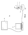
- FIG. 1 is a schematic structural diagram of an input system according to a first embodiment of the present disclosure
- FIG. 2 is a functional block diagram of the input system shown in FIG. 1 ;
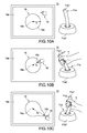
- FIGS. 3A to 3C are diagrams showing examples of an operation of the input system shown in FIG. 1 ;
- FIG. 4 is a flowchart showing an example of a flow of processing of a controller in the input system shown in FIG. 1 ;
- FIG. 5 is a flowchart showing an example of a flow of processing of the controller in the input system shown in FIG. 1 ;
- FIG. 6 is a flowchart showing an example of a flow of processing of the controller in the input system shown in FIG. 1 ;
- FIG. 7 is a flowchart showing an example of a flow of processing of the controller in the input system shown in FIG. 1 ;
- FIG. 8 is a schematic structural diagram of an input system according to a second embodiment of the present disclosure.
- FIG. 9 is a functional block diagram of the input system shown in FIG. 8 ;
- FIGS. 10A to 10C are diagrams showing examples of an operation of the input system shown in FIG. 8 ;
- FIG. 11 is a functional block diagram of an electronic apparatus according to a third embodiment of the present disclosure.
- FIGS. 12A to 12C are diagrams showing examples of an operation of the electronic apparatus shown in FIG. 11 ;
- FIG. 13 is a functional block diagram of an input device according to a fourth embodiment of the present disclosure.
- FIG. 1 is a schematic structural diagram of an input system 10 according to a first embodiment of the present disclosure.
- FIG. 2 is a functional block diagram of the input system 10 shown in FIG. 1 .
- the input system 10 includes an operation portion 11 , a controller 12 , a detection portion 13 , and a display portion 14 .
- the operation portion 11 receives an input operation made by a hand h of a user.
- the input system 10 includes a vibration portion 17 (see FIG. 2 ) inside the operation portion 11 .
- the controller 12 includes an antenna 19 that wirelessly transmits a signal for driving the vibration portion 17 .
- the detection portion 13 and the display portion 14 are connected by wires to the controller 12 .
- the operation portion 11 is structured as an input device.
- the user holds the operation portion 11 with the hand h and makes an input operation by moving the operation portion 11 .
- the detection portion 13 detects a position of the operation portion 11 as the input operation of the user and outputs the detection result to the controller 12 .
- the controller 12 controls display on a screen 14 a of the display portion 14 based on the detection result input from the detection portion 13 .
- the operation portion 11 includes a casing that is formed as a bar so that the user can easily grab it with the hand h, and the vibration portion 17 provided inside the casing.
- the vibration portion 17 can be vibrated, and the operation portion 11 is structured such that the vibration of the vibration portion 17 favorably propagates to the hand h of the user via the casing.
- the vibration portion 17 is switched between an on state and an off state by the controller 12 .
- the on state is a state where the vibration portion 17 can be vibrated
- the off state is a state where the vibration portion 17 cannot be vibrated.
- the vibration direction of the vibration portion 17 in the on state may either be isotropic or anisotropic.
- the vibration portion 17 only needs to be capable of being vibrated in at least one direction, but may be capable of being vibrated in a plurality of directions.
- the vibration portion 17 capable of being vibrated in the plurality of directions may have such a structure that the controller 12 can control the vibration direction thereof.
- any of controllers that use various actuators such as a motor can be adopted.
- the operation portion 11 may be structured such that input operations other than the movement thereof can also be input by the user.
- an operation button, a slide lever, and the like exposed from the casing of the operation portion 11 are provided as appropriate.
- a CCD (Charge Coupled Device) image sensor capable of detecting a position of the operation portion 11 is used.
- a CMOS (Complementary Metal Oxide Semiconductor) image sensor may also be used as the detection portion 13 .
- a timing at which the detection portion 13 detects the position of the operation portion 11 is controlled by the controller 12 .
- the detection portion 13 detects the position of the operation portion 11 every time a timing signal transmitted from the controller 12 is received. It should be noted that the detection portion 13 may be structured to constantly monitor the position of the operation portion 11 , but with a structure to detect the position of the operation portion 11 at predetermined timings, the overall power consumption is reduced more.
- the controller 12 a generally-used personal computer is used.
- the controller 12 only needs to process the detection result (positional information of operation portion 11 ) input from the detection portion 13 and output it to the display portion 14 and the operation portion 11 . Therefore, the controller 12 does not need to include all structural elements of the generally-used personal computer.
- the antenna 19 mounted on the controller 12 an antenna capable of transmitting an output signal of the controller 12 to the operation portion 11 only needs to be used.
- a display including a generally-used screen 14 a is used as the display portion 14 .
- a form of the display used as the display portion 14 is not limited. Examples of such a display form include liquid crystal, plasma, and organic EL (Electro-Luminescence).
- the controller 12 executes a predetermined drive as well as switch the vibration portion 17 from the off state to the on state based on an input operation to the operation portion 11 detected by the detection portion 13 , the input operation being made by the hand h of the user. As a result, an elastic sense is presented to the hand h of the user.
- FIGS. 3A to 3C are schematic diagrams each showing display on the screen 14 a of the display portion 14 and an operation of the operation portion 11 .
- a toy hammer 5 as an operation target that moves by an input operation made by the hand h of the user with respect to the operation portion 11 and a spring toy 6 as an object that receives an action from the hammer 5 are displayed as an image.
- a generally-used hammer that is formed of a resin and whose hammering portion is formed as bellows is assumed.
- the spring toy 6 a toy including a spring S whose lower end portion 6 a is fixed and a spherical head portion 6 c attached to an upper end portion 6 b of the spring S is assumed.
- the head portion 6 c can make up-and-down motions, and the spring S is extendable in accordance with the up-and-down motions of the head portion 6 c .
- a natural length of the spring S (distance between lower end portion 6 a and upper end portion 6 b ) of the spring toy 6 is represented by a.
- the controller 12 reproduces, as well as display a series of operations of the hammer 5 hammering the head portion 6 c of the spring toy 6 on the screen 14 a based on the detection result of the detection portion 13 , virtual stimulations corresponding to the elasticity of the spring S, that are supposedly applied to the hammer 5 along with the operations.
- the controller 12 reproduces the virtual stimulations that are supposedly applied to the hammer 5 by vibrating the vibration portion 17 in the operation portion 11 , and thus presents an elastic sense of the spring S to the user.
- the detection portion 13 When the user makes an input operation of swinging down the operation portion 11 at a time the screen 14 a is in the state shown in FIG. 3A , the detection portion 13 successively detects the position of the operation portion 11 and outputs the detection result to the controller 12 . Based on the detection result from the detection portion 13 , the controller 12 displays an operation of the hammer 5 corresponding to the operation of the operation portion 11 on the screen 14 a . Specifically, the controller 12 displays, on the screen 14 a , an operation in which the hammer 5 moves to the head portion 6 c of the spring toy 6 and pushes down the head portion 6 c of the spring toy 6 so that the spring S of the spring toy 6 contracts.
- the detection portion 13 successively detects the position of the operation portion 11 and outputs the detection result to the controller 12 .
- the controller 12 displays an operation of the hammer 5 corresponding to the operation of the operation portion 11 on the screen 14 a .
- the controller 12 displays, on the screen 14 a , an operation in which the hammer 5 is pushed up together with the head portion 6 c of the spring toy 6 , and the spring S of the spring toy 6 extends.
- an elastic force of an actual spring becomes larger as a contraction force becomes larger. Therefore, in moving the hammer 5 , the user presumes that a resistive force applied to the hammer 5 from the head portion 6 c of the spring toy 6 becomes larger as the contraction force of the spring S becomes larger.
- the controller 12 expresses the elastic sense in which the resistive force applied to the hammer 5 from the head portion 6 c of the spring toy 6 becomes larger, by increasing an amplitude A of the vibration of the vibration portion 17 in the operation portion 11 .
- the controller 12 can determine the amplitude A at a time the hammer 5 pushes down the head portion 6 c of the spring toy 6 further by the following function.
- A k 1 *( a ⁇ a 1 ) 2 +l 1 ( k 1 and l 1 are each a predetermined constant) (1)
- the length (a ⁇ a 1 ) represents a contraction amount of the spring S.
- the function expressing the amplitude A of the vibration portion 17 is not limited to the quadratic function (1) of the contraction amount (a ⁇ a 1 ), and other functions that use the contraction amount (a ⁇ a 1 ) as a variable may be used instead.
- a linear function of the contraction amount (a ⁇ a 1 ) or a cubic function of the contraction amount (a ⁇ a 1 ) may be used.
- the spring S having a smaller spring constant than in the case of using the function (1) can be expressed.
- the cubic function of the contraction amount (a ⁇ a 1 ) the spring S having a larger spring constant than in the case of using the function (1) can be expressed.
- the controller 12 displays, on the screen 14 a , an operation in which the head portion 6 c of the spring toy 6 moves upward with the hammer 5 , and the spring S of the spring toy 6 extends as shown in FIG. 3C .
- the controller 12 displays, on the screen 14 a , an operation in which the hammer 5 is lowered together with the head portion 6 c of the spring toy 6 and the spring S of the spring toy 6 contracts.
- an elastic force of an actual spring becomes larger as an extension amount increases. Therefore, in moving the hammer 5 , the user presumes that a resistive force applied to the hammer 5 from the head portion 6 c of the spring toy 6 becomes larger as the extension amount of the spring S increases.
- the controller 12 expresses the elastic sense in which the resistive force applied to the hammer 5 from the head portion 6 c of the spring toy 6 becomes larger, by increasing the amplitude A of the vibration of the vibration portion 17 in the operation portion 11 .
- the controller 12 can determine the amplitude A at a time the hammer 5 lifts up the head portion 6 c of the spring toy 6 by the following function.
- A k 2 *( a 2 ⁇ a ) 2 +l 2 ( k 2 and l 2 are each a predetermined constant) (2)
- the length (a 2 ⁇ a) represents the extension amount of the spring S.
- the function expressing the amplitude A of the vibration portion 17 is not limited to the quadratic function (2) of the extension amount (a 2 ⁇ a), and other functions that use the extension amount (a 2 ⁇ a) as a variable may be used instead.
- a linear function of the extension amount (a 2 ⁇ a) or a cubic function of the extension amount (a 2 ⁇ a) may be used.
- the spring S having a smaller spring constant than in the case of using the function (2) can be expressed.
- the cubic function of the extension amount (a 2 ⁇ a) the spring S having a larger spring constant than in the case of using the function (2) can be expressed.
- the controller 12 displays an operation in which the spring S of the spring toy 6 returns to the natural length a as the hammer 5 is released from the head portion 6 c of the spring toy 6 , and controls the display of the screen 14 a to set it back to the state shown in FIG. 3A .
- the values of the constants k 1 , k 2 , l 1 , and l 2 can be determined arbitrarily.
- the amplitude A of the vibration portion 17 at the time the spring S is the natural length a becomes 0.
- the constants l 1 and l 2 are larger than 0, the amplitude A of the vibration portion 17 at the time the spring S is the natural length a is larger than 0.
- the constants l 1 and l 2 can be set to be, for example, several ⁇ m in view of a vibration detection threshold value.
- the amplitude A of the vibration portion 17 is controlled by the functions (1) and (2).
- the amplitude A of the vibration portion 17 is 0 regardless of the functions (1) and (2).
- represents a displacement amount of the spring S.
- FIG. 4 is a flowchart showing a flow of processing of the controller 12 that is based on the descriptions above.
- FIG. 4 shows the flow of processing of the controller 12 in a state where the hammer 5 is in contact with the head portion 6 c of the spring toy 6 .
- the controller 12 determines whether an input operation is made by the user and ends, when an input operation is made by the user, processing while the vibration portion 17 is in the on state.
- the controller 12 turns on the vibration portion 17 and determines whether the spring S of the spring toy 6 is contracted (or extended). It should be noted that although the state where the spring S is the natural length a is included in the extension state in FIG. 4 , the state where the spring S is the natural length a may instead be included in the contraction state.
- the controller 12 determines which of the contraction direction and the extension direction of the spring S the input operation of the user is made in.
- the controller 12 increases the amplitude A of the vibration portion 17 based on a result of calculating the displacement amount.
- the controller 12 lowers the amplitude A of the vibration portion 17 based on the result of calculating the displacement amount.
- the controller 12 determines which of the extension direction and the contraction direction of the spring S the input operation of the user is made in.
- the controller 12 increases the amplitude A of the vibration portion 17 based on the result of calculating the displacement amount.
- the controller 12 lowers the amplitude A of the vibration portion 17 based on the result of calculating the displacement amount.
- the controller 12 updates the image displayed on the screen 14 a to an image corresponding to the relevant state.
- the controller 12 may determine the amplitude A of the vibration portion 17 using a function that includes other variables in addition to the length x of the spring S.
- the other variables include a movement velocity and acceleration of the hammer 5 that are based on the input operation to the operation portion 11 .
- FIG. 5 is a flowchart showing a flow of processing of the controller 12 , that uses a function including the movement velocity of the hammer 5 as the variable.
- FIG. 5 shows the flow of processing of the controller 12 in a state where the hammer 5 is in contact with the head portion 6 c of the spring toy 6 .
- the flow up to the step of determining, by the controller 12 , whether the spring S of the spring toy 6 is contracted (or extended) is the same as that of FIG. 4 .
- the controller 12 determines which of the contraction direction and the extension direction of the spring S the input operation of the user is made in.
- the controller 12 increases the amplitude A of the vibration portion 17 based on a result of calculating the movement velocity.
- the controller 12 lowers the amplitude A of the vibration portion 17 based on the result of calculating the movement velocity.
- the controller 12 determines which of the extension direction and the contraction direction of the spring S the input operation of the user is made in.
- the controller 12 increases the amplitude A of the vibration portion 17 based on the result of calculating the movement velocity.
- the controller 12 lowers the amplitude A of the vibration portion 17 based on the result of calculating the movement velocity.
- the controller 12 updates the image displayed on the screen 14 a to an image corresponding to the relevant state.
- the controller 12 may set the frequency f of the vibration portion 17 to be constant or may change it as appropriate. By changing the frequency f of the vibration portion 17 as appropriate, the controller 12 can more realistically express the elastic sense of the spring S.
- the controller 12 can determine the frequency f of the vibration portion 17 by the following function (4) in the same manner as in determining the amplitude A of the vibration portion 17 using the function (3).
- f m/
- the function expressing the frequency f of the vibration portion 17 is not limited to the function (4), and a different function that uses the displacement amount
- the frequency f of the vibration portion 17 is determined unambiguously in accordance with the length x of the spring S from the natural length a thereof. As a result, the user feels the sense in which the spring S is trying to return to the natural length a in accordance with the length x of the spring S.
- the frequency f is lowered when the spring S additionally contracts. Accordingly, the user feels a sense that the contraction of the spring S is being hampered (deceleration sense). Moreover, the frequency f increases when the spring S extends. As a result, the user feels a sense that the extension of the spring S is being accelerated (acceleration sense).
- the frequency f is lowered when the spring S additionally extends. Accordingly, the user feels a sense that the extension of the spring S is being hampered (deceleration sense). Moreover, the frequency f increases when the spring S contracts. As a result, the user feels a sense that the contraction of the spring S is being accelerated (acceleration sense).
- the values of the constants m and n can be determined arbitrarily.
- the constant n is 0, the frequency f of the vibration portion 17 in the case where the spring S is the natural length a becomes 0.
- the constant n is larger than 0, the frequency f of the vibration portion 17 in the case where the spring S is the natural length a becomes larger than 0.
- the constant n can be set to be, for example, about 100 Hz.
- FIG. 6 is a flowchart showing a flow of processing of the controller 12 that is based on the descriptions above.
- FIG. 6 shows the flow of processing of the controller 12 in a state where the hammer 5 is in contact with the head portion 6 c of the spring toy 6 .
- the flow up to the step of determining, by the controller 12 , whether the spring S of the spring toy 6 is contracted (or extended) is the same as that of FIG. 4 .
- the controller 12 determines which of the contraction direction and the extension direction of the spring S the input operation of the user is made in.
- the controller 12 lowers the frequency f of the vibration portion 17 based on a result of calculating the displacement amount
- the controller 12 raises the frequency f of the vibration portion 17 based on the result of calculating the displacement amount
- the controller 12 determines which of the extension direction and the contraction direction of the spring S the input operation of the user is made in.
- the controller 12 lowers the frequency f of the vibration portion 17 based on the result of calculating the displacement amount
- the controller 12 raises the frequency f of the vibration portion 17 based on the result of calculating the displacement amount
- the controller 12 updates the image displayed on the screen 14 a to an image corresponding to the relevant state.
- the frequency f may be changed based on a speed of the input operation to the operation portion 11 .
- the controller 12 can determine the frequency f by the following function that uses, as a variable, the movement velocity v of the hammer 5 based on the input operation to the operation portion 11 .
- f pv+q ( p and q are each a constant) (5)
- the function expressing the frequency f of the vibration portion 17 is not limited to the function (5), and a different function that uses the movement velocity v of the hammer 5 that is based on the input operation to the operation portion 11 as a variable may also be used.
- the function expressing the frequency f of the vibration portion 17 may be a function that uses an acceleration of the hammer 5 that is based on the input operation to the operation portion 11 as a variable.
- the values of the constants p and q can be determined arbitrarily.
- the constant q is 0, the frequency f of the vibration portion 17 in the case where the movement velocity v of the hammer 5 is 0 becomes 0.
- the constant q is larger than 0, the frequency f of the vibration portion 17 in the case where the movement velocity v of the hammer 5 is 0 becomes larger than 0.
- the constant q can be set to be, for example, about 100 Hz.
- the controller 12 can also determine a change amount ⁇ f of the frequency f by the following function (6) that uses, as a variable, the movement velocity v of the hammer 5 that is based on the input operation to the operation portion 11 .
- ⁇ f ry ( r is a constant) (6)
- the function expressing ⁇ f is not limited to the function (6), and a different function that uses the movement velocity v of the hammer 5 that is based on the input operation to the operation portion 11 as a variable may also be used.
- the function expressing ⁇ f may be a function that uses an acceleration of the hammer 5 that is based on the input operation to the operation portion 11 as a variable. It should be noted that the value of the constant r can be determined arbitrarily.
- FIG. 7 is a flowchart showing a flow of processing of the controller 12 that is based on the descriptions above.
- FIG. 7 shows the flow of processing of the controller 12 in a state where the hammer 5 is in contact with the head portion 6 c of the spring toy 6 .
- the flow up to the step of determining, by the controller 12 , whether the spring S of the spring toy 6 is contracted (or extended) is the same as that of FIG. 4 .
- the controller 12 determines which of the contraction direction and the extension direction of the spring S the input operation of the user is made in.
- the controller 12 lowers the frequency f of the vibration portion 17 only by ⁇ f based on a result of calculating the movement velocity v.
- the controller 12 raises the frequency f of the vibration portion 17 only by ⁇ f based on the result of calculating the movement velocity v.
- the controller 12 determines which of the extension direction and the contraction direction of the spring S the input operation of the user is made in.
- the controller 12 lowers the frequency f of the vibration portion 17 only by ⁇ f based on the result of calculating the movement velocity v.
- the controller 12 raises the frequency f of the vibration portion 17 only by ⁇ f based on the result of calculating the movement velocity v.
- the controller 12 updates the image displayed on the screen 14 a to an image corresponding to the relevant state.
- the controller 12 can determine the vibration condition of the vibration portion 17 (amplitude A and frequency f) so as to present a realistic elastic sense to the user. Specifically, the controller 12 can determine, based on the input operation to the operation portion 11 , the vibration condition of the vibration portion 17 (amplitude A and frequency f) using a function obtained by combining the functions 3, 4, 5, and the like as appropriate.
- the input system 10 of this embodiment is structured to receive vibrations matching the extension and contraction of the spring S of the spring toy 6 on the screen 14 a viewed by the user.
- the user visually as well as auditorially receives an elastic sense. Therefore, the input system 10 can present to the user an elastic sense that is extremely close to that of an actual spring.
- the controller 12 can determine the vibration condition of the vibration portion 17 as appropriate.
- the controller 12 may set the vibration condition of the vibration portion 17 to be constant or may change the vibration condition of the vibration portion 17 based on the position of the hammer 5 on the screen 14 a.
- the controller 12 basically does not cause the vibration portion 17 to vibrate when the user is not moving the operation portion 11 .
- the user feels an awkwardness when the vibration of the vibrating vibration portion 17 suddenly stops. This is considered to be based on an experience of the user that, in an actual spring, the vibration in the contraction and extension direction stays for a while after the spring is elastically deformed and stops.
- the controller 12 gradually lowers, for a predetermined time T after the operation portion 11 stops, the amplitude A of the vibration portion 17 until the amplitude A becomes 0 from an amplitude A 1 obtained right before the operation portion 11 stops.
- the amplitude A in the predetermined time T can be expressed by the following function using an elapse time t from when the operation portion 11 is put to a still state, for example.
- A (( T ⁇ t )/ T ) A 1
- FIG. 8 is a schematic structural diagram of an input system 10 a according to a second embodiment of the present disclosure.
- FIG. 9 is a functional block diagram of the input system 10 a shown in FIG. 8 .
- the input system 10 a of this embodiment has the same structure as the input system 10 according to the first embodiment except for the following structures.
- a detection portion 13 a of the input system 10 a is provided inside an operation portion 11 a .
- the operation portion 11 a and the display portion 14 are connected to the controller 12 by wires.
- the operation portion 11 a is structured as an input device and is a joystick including a lever portion 11 a 1 that is grabbed by the hand h of the user and receives an input operation and a pedestal portion 11 a 2 that supports a lower end portion of the lever portion 11 a 1 such that the lever portion 11 a 1 is movable using the lower end portion thereof as a fulcrum.
- the vibration portion 17 is provided inside the lever portion 11 a 1
- the detection portion 13 a is provided inside the pedestal portion 11 a 2 .
- the detection portion 13 a detects an input operation of the user with respect to the lever portion 11 a 1 of the operation portion 11 a .
- the detection portion 13 a detects an operation of the lever portion 11 a 1 and outputs the detection result to the controller 12 .
- a type of the detection portion 13 a is not limited as long as it is a sensor capable of detecting an operation at the lower end portion of the lever portion 11 a 1 .
- As the structure of the detection portion 13 a a structure that uses a displacement sensor, a velocity sensor, an acceleration sensor, an angle sensor, an angular velocity sensor, or the like may be used.
- the shape of the operation portion 11 a may be the same as that of the operation portion 11 according to the first embodiment.
- the operation portion 11 a may have a structure in which the vibration portion 17 and the detection portion 13 a are provided inside a bar-type casing. Therefore, the detection portion 13 a operates together with the operation portion 11 a .
- a structure capable of detecting its own operation is used.
- a structure that uses, for example, a triaxial motion sensor or a six-axis motion sensor is used as the structure of the detection portion 13 a .
- the controller 12 drives the vibration portion 17 based on the input operation that has been detected by the detection portion 13 a and made by the hand h of the user with respect to the operation portion 11 a , to present an elastic sense to the hand h of the user.
- FIGS. 10A to 10C are each a diagram schematically showing display of the screen 14 a of the display portion 14 and an operation of the operation portion 11 a .
- Displayed on the screen 14 a is an image including a hand-shaped pointer 15 pointing, with an index finger, an operation target that moves by an input operation made by the hand h of the user with respect to the operation portion 11 a and a rubber ball 16 as an object that receives an action from the pointer 15 .
- the rubber ball 16 is a sphere having a fixed center portion 16 a , the inside of the sphere being filled with air sealed by an outer circumferential portion 16 b made of rubber.
- the outer circumferential portion 16 b of the rubber ball 16 can be elastically deformed about the center portion 16 a .
- a radius of the rubber ball 16 (distance between center portion 16 a and outer circumferential portion 16 b ) in a steady state is represented by b.
- the controller 12 reproduces, as well as display on the screen 14 a a series of operations in which the pointer 15 (tip end portion of index finger) pokes the rubber ball 16 based on the detection result of the detection portion 13 a , virtual stimulations corresponding to the elasticity of the rubber ball 16 , that are supposedly applied to the pointer 15 along with the operations.
- the controller 12 reproduces the virtual stimulations that are supposedly applied to the pointer 15 by vibrating the vibration portion 17 inside the operation portion 11 a , and thus presents an elastic sense of the rubber ball 16 to the user.
- the detection portion 13 a detects the operation of the operation portion 11 a and outputs the detection result to the controller 12 . Based on the detection result from the detection portion 13 a , the controller 12 displays an operation of the pointer 15 corresponding to the operation of the lever portion 11 a 1 of the operation portion 11 a on the screen 14 a .
- the controller 12 displays, on the screen 14 a , an operation in which the pointer 15 moves to the outer circumferential portion 16 b of the rubber ball 16 and elastically deforms the outer circumferential portion 16 b of the rubber ball 16 toward the center portion 16 a.
- the detection portion 13 a detects the operation of the lever portion 11 a 1 of the operation portion 11 a and outputs the detection result to the controller 12 .
- the controller 12 Based on the detection result from the detection portion 13 a , the controller 12 displays an operation of the pointer 15 corresponding to the operation of the lever portion 11 a 1 of the operation portion 11 a on the screen 14 a .
- the controller 12 displays, on the screen 14 a , an operation in which the pointer 15 moves away from both the center portion 16 a of the rubber ball 16 and the outer circumferential portion 16 b thereof so that the rubber ball 16 restores its spherical shape.
- FIG. 11 is a functional block diagram of an electronic apparatus 20 according to a third embodiment of the present disclosure.
- the electronic apparatus 20 of this embodiment has the same structure as the input system 10 according to the first embodiment except for the following structures.
- the electronic apparatus 20 includes a casing 28 .
- an operation portion 21 , a controller 22 , a detection portion 23 , a display portion 24 , and a vibration portion 27 are integrally formed with the casing 28 unlike the input system 10 according to the first embodiment.
- FIGS. 12A to 12C are diagrams each showing display of a screen 24 a of the display portion 24 of the electronic apparatus 20 and an operation of the operation portion 21 .
- the casing 28 of the electronic apparatus 20 is capable of being held by a hand of a user.
- the electronic apparatus 20 receives an input operation made by a finger f (thumb) of the user with respect to the operation portion 21 in a state where the user is holding the electronic apparatus 20 .
- the operation portion 21 and the screen 24 a are exposed from the same surface. Therefore, in the electronic apparatus 20 , the user can make an input operation to the operation portion 21 with the finger f while watching the screen 24 a.
- the operation portion 21 is structured as a small joystick that is operated by the finger f of the user.
- the vibration portion 27 is adjacent to the operation portion 21 . Therefore, the vibration of the vibration portion 27 is favorably propagated to the finger f of the user via the operation portion 21 .
- the detection portion 23 detects an input operation made to the operation portion 21 by the user.
- the detection portion 23 detects an operation of the operation portion 21 and outputs the detection result to the controller 22 .
- a type of the detection portion 23 is not limited as long as it is a sensor capable of detecting an operation of the operation portion 21 .
- As the structure of the detection portion 23 a structure that uses a displacement sensor, a velocity sensor, an acceleration sensor, an angle sensor, an angular velocity sensor, or the like may be used.
- the controller 22 drives the vibration portion 27 based on the input operation that has been detected by the detection portion 23 and made by the finger f of the user with respect to the operation portion 21 , to present an elastic sense to the finger f of the user.
- Displayed on the screen 24 a is an image including a boxing glove 25 as an operation target that moves by an input operation made by the finger f of the user with respect to the operation portion 21 and a spring toy 26 as an object that receives an action from the boxing glove 25 .
- a boxing glove is attached to a tip end of a stick that extends from a right end of the screen 24 a toward the center.
- the spring toy 26 is a spring toy including a spring S that extends from a left end of the screen 24 a toward the center and whose left end portion 26 a is fixed, and a spherical punching ball 26 c attached to a right end portion 26 b of the spring S.
- the punching ball 26 c is movable in the lateral direction, and the spring S can be extended and contracted in accordance with an operation of the punching ball 26 c .
- the natural length of the spring S of the spring toy 26 (distance between left end portion 26 a and right end portion 26 b ) is represented by c.
- the controller 22 reproduces, as well as display on the screen 24 a a series of operations in which the boxing glove 25 punches the punching ball 26 c based on the detection result of the detection portion 23 , virtual stimulations corresponding to the elasticity of the spring S, that are supposedly applied to the boxing glove 25 along with the operations.
- the controller 22 reproduces the virtual stimulations that are supposedly applied to the boxing glove 25 by vibrating the vibration portion 27 inside the operation portion 21 , and thus presents an elastic sense of the spring S to the user.
- the detection portion 23 detects the operation of the operation portion 21 and outputs the detection result to the controller 22 .
- the controller 22 displays an operation of the boxing glove 25 corresponding to the operation of the operation portion 21 on the screen 24 a .
- the controller 22 displays, on the screen 24 a , an operation in which the boxing glove 25 moves to the punching ball 26 c and pushes the punching ball 26 c in the left-hand direction so that the spring S of the spring toy 26 contracts.
- the detection portion 23 detects the operation of the operation portion 21 and outputs the detection result to the controller 22 .
- the controller 22 displays an operation of the boxing glove 25 corresponding to the operation of the operation portion 21 on the screen 24 a .
- the controller 22 displays, on the screen 24 a , an operation in which the boxing glove 25 moves in the right-hand direction with the punching ball 26 c so that the spring S of the spring toy 26 extends.
- an elastic force of an actual spring becomes larger as a contraction amount increases. Therefore, in moving the boxing glove 25 , the user presumes that a resistive force applied to the boxing glove 25 from the punching ball 26 c of the spring toy 26 becomes larger as the contraction amount of the spring S increases.
- the controller 22 expresses the elastic sense in which the resistive force applied to the boxing glove 25 from the punching ball 26 c of the spring toy 26 becomes larger, by increasing an amplitude A of the vibration of the vibration portion 27 in the operation portion 21 .
- an elastic force of an actual spring becomes larger as a extension amount increases. Therefore, in moving the boxing glove 25 , the user presumes that a resistive force applied to the boxing glove 25 from the punching ball 26 c of the spring toy 26 becomes larger as the extension amount of the spring S increases.
- the controller 22 expresses the elastic sense in which the resistive force applied to the boxing glove 25 from the punching ball 26 c of the spring toy 26 becomes larger, by increasing an amplitude A of the vibration of the vibration portion 27 in the operation portion 21 .
- FIG. 13 is a functional block diagram of an input device 30 according to a fourth embodiment of the present disclosure.
- the input device 30 of this embodiment has the same structure as the input system 10 according to the first embodiment except for the following structures.
- the input device 30 does not include a structural element that can be visually recognized by the user, such as a screen, unlike the input system 10 according to the first embodiment.
- the input device 30 includes a casing 31 .
- a controller 32 , a detection portion 33 , and a vibration portion 37 are integrally formed with the casing 31 .
- the casing 31 itself constitutes an operation portion that receives an input operation from a hand of the user.
- the casing 31 is formed as a bar that can be grabbed by the hand of the user.
- the detection portion 33 operates with the casing 31 .
- a structure of the detection portion 33 a structure capable of detecting its own operation is used.
- a structure that uses, for example, a triaxial motion sensor or a six-axis motion sensor is used.
- the controller 32 drives the vibration portion 37 of the casing 31 based on an input operation that has been made by the user with respect to the casing 31 and detected by the detection portion 33 , to present an elastic sense to the user.
- the input device 30 is used for the user to move an operation target in virtual space.
- the operation target does not need to be visually recognizable by the user as long as it exists in the virtual space.
- Example of the operation target in the virtual space is a pointer that is visually recognizable by a user wearing a head mount display (not shown).
- the detection portion 33 detects a position of the operation target and outputs the detection result to the controller 32 .
- the controller 32 grasps a positional relationship between the operation target and a predetermined first position in the space.
- the controller 32 drives the vibration portion 37 based on the positional relationship of the operation target with respect to the first position, and thus presents an elastic sense as if there is a deformable object at the reference position to the user.
- the controller 32 increases the amplitude of the vibration portion 37 when the operation target approaches the first position by an input operation made by the user with respect to the input device 30 and decreases the amplitude of the vibration portion 37 when the operation target moves away from the first position.
- the shape of the operation target that moves by an input operation of the user and the shape of the object that receives an action from the operation target can be set arbitrarily.
- the connections of the structures described in the specification may either be by wires or without wires.
- the present disclosure may of course adopt a structure that presents, to the user, senses other than an elastic sense by the vibration.
- the presentable senses include a viscous sense, an inertial sense, a frictional sense, and an impact sense.
- the controller can determine the vibration conditions by appropriately combining those functions with the functions (3) to (5) above.
- An input device including:
- an operation portion configured to receive an input operation made by a user
- a vibration portion configured to vibrate the operation portion
- a detection portion configured to detect the input operation
- a controller configured to determine a vibration condition of the vibration portion based on the input operation detected by the detection portion and present an elastic sense to the user by driving the vibration portion under the determined vibration condition.
- the controller controls a movement of an operation target displayed on a screen based on the input operation and determines the vibration condition based on a relative position between an object and the operation target displayed on the screen.
- the object is an image that can be deformed according to the relative position with respect to the operation target.
- the object is an image representing an elastic body that can be elastically deformed.
- the controller determines the vibration condition using a function that uses at least one of a distance between the operation target and the object and a movement velocity of the operation target as a variable.
- the controller determines the vibration condition using a function that uses at least one of a distance between a predetermined first position and the operation target and a movement velocity of the operation target as a variable.
- the controller sets at least one of an amplitude and frequency of the vibration portion to become larger as the operation target approaches a predetermined first position from a second position different from the first position.
- the controller sets at least one of an amplitude and frequency of the vibration portion to become larger as the operation target moves farther away from a predetermined first position than a second position different from the first position.
- the controller attenuates an amplitude of the vibration portion after the operation target stops.
- An input system including:
- an input device including an operation portion that receives an input operation made by a user and a vibration portion that vibrates the operation portion;
- a detection portion configured to detect the input operation
- a controller configured to determine a vibration condition of the vibration portion based on the input operation detected by the detection portion and present an elastic sense to the user by driving the vibration portion under the determined vibration condition.
- the detection portion is integrated with the input device.
- An electronic apparatus including:
- an operation portion configured to receive an input operation made by a user
- a vibration portion configured to vibrate the operation portion
- a detection portion configured to detect the input operation
- a display portion including a screen for displaying an image
- a controller configured to control a movement of an operation target displayed on the screen based on the input operation, determine a vibration condition of the vibration portion based on a relative position between an object and the operation target displayed on the screen, and present an elastic sense to the user by driving the vibration portion under the determined vibration condition.
- a sense presentation method including:
Abstract
Description
A=k 1*(a−a 1)2 +l 1(k 1 and l 1 are each a predetermined constant) (1)
A=k 2*(a 2 −a)2 +l 2 (k 2 and l 2 are each a predetermined constant) (2)
A=k*|a−x| 2 +l (k and l are each a predetermined constant) (3)
f=m/|a−x|+n (m and n are each a constant) (4)
f=pv+q (p and q are each a constant) (5)
Δf=ry (r is a constant) (6)
A=((T−t)/T)A 1
Claims (16)
Applications Claiming Priority (2)
| Application Number | Priority Date | Filing Date | Title |
|---|---|---|---|
| JP2012184042A JP6043544B2 (en) | 2012-08-23 | 2012-08-23 | Input device, input system, electronic device, and sensory presentation method |
| JP2012-184042 | 2012-08-23 |
Publications (2)
| Publication Number | Publication Date |
|---|---|
| US20140059255A1 US20140059255A1 (en) | 2014-02-27 |
| US9489041B2 true US9489041B2 (en) | 2016-11-08 |
Family
ID=50149056
Family Applications (1)
| Application Number | Title | Priority Date | Filing Date |
|---|---|---|---|
| US13/962,595 Active US9489041B2 (en) | 2012-08-23 | 2013-08-08 | Input device, input system, electronic apparatus, and sense presentation method |
Country Status (3)
| Country | Link |
|---|---|
| US (1) | US9489041B2 (en) |
| JP (1) | JP6043544B2 (en) |
| CN (2) | CN108170276B (en) |
Families Citing this family (4)
| Publication number | Priority date | Publication date | Assignee | Title |
|---|---|---|---|---|
| WO2015163169A1 (en) * | 2014-04-23 | 2015-10-29 | ソニー株式会社 | Image processing device and method |
| CN106774853A (en) * | 2016-11-28 | 2017-05-31 | 珠海市魅族科技有限公司 | A kind of seismaesthesia feedback method and terminal |
| JP6842368B2 (en) * | 2017-05-19 | 2021-03-17 | 任天堂株式会社 | Information processing programs, information processing systems, information processing devices, and information processing methods |
| US11775071B1 (en) * | 2022-03-08 | 2023-10-03 | Microsoft Technology Licensing, Llc | Haptic feedback from a computing accessory |
Citations (12)
| Publication number | Priority date | Publication date | Assignee | Title |
|---|---|---|---|---|
| JPH07146751A (en) | 1993-05-11 | 1995-06-06 | Matsushita Electric Ind Co Ltd | Force sense presentation device, data input device and data input apparatus |
| US6200253B1 (en) * | 1995-10-09 | 2001-03-13 | Nintendo Co., Ltd. | Controller pack |
| US20020021277A1 (en) | 2000-04-17 | 2002-02-21 | Kramer James F. | Interface for controlling a graphical image |
| US20080043042A1 (en) * | 2006-08-15 | 2008-02-21 | Scott Bassett | Locality Based Morphing Between Less and More Deformed Models In A Computer Graphics System |
| JP2009009412A (en) | 2007-06-28 | 2009-01-15 | Canon Inc | Information presentation device and information presentation method |
| WO2009035100A1 (en) | 2007-09-14 | 2009-03-19 | National Institute Of Advanced Industrial Science And Technology | Virtual reality environment creating device, and controller device |
| WO2010038822A1 (en) | 2008-10-01 | 2010-04-08 | 株式会社ソニー・コンピュータエンタテインメント | Information processing apparatus, information processing method, information recording medium, and program |
| US7980952B2 (en) * | 2007-06-20 | 2011-07-19 | Nintendo Co., Ltd. | Storage medium having information processing program stored thereon and information processing apparatus |
| JP2011159100A (en) | 2010-02-01 | 2011-08-18 | Nippon Telegr & Teleph Corp <Ntt> | Successive similar document retrieval apparatus, successive similar document retrieval method and program |
| US20120065784A1 (en) * | 2010-09-13 | 2012-03-15 | Philip Feldman | Providing kinetic feedback for computer-human interaction in virtual or remote operation environments |
| US8226484B2 (en) * | 2009-08-27 | 2012-07-24 | Nintendo Of America Inc. | Simulated handlebar twist-grip control of a simulated vehicle using a hand-held inertial sensing remote controller |
| US20130229371A1 (en) * | 2012-03-02 | 2013-09-05 | Samsung Electronics Co., Ltd. | Method for displaying pages of e-book and mobile device adapted thereto |
Family Cites Families (8)
| Publication number | Priority date | Publication date | Assignee | Title |
|---|---|---|---|---|
| JP2002082751A (en) * | 2000-09-08 | 2002-03-22 | Mitsubishi Electric Corp | Device for interaction with virtual space and virtual space system applied with the same |
| JP2008225690A (en) * | 2007-03-09 | 2008-09-25 | Sony Corp | Vibration body, tactile sense function-equipped input device, and electronic equipment |
| WO2009065436A1 (en) * | 2007-11-19 | 2009-05-28 | Nokia Corporation | Input device |
| JP2009134473A (en) * | 2007-11-29 | 2009-06-18 | Sony Corp | Pressing detection sensor, input device and electronic equipment |
| CN103272385B (en) * | 2008-10-27 | 2016-09-28 | 索尼电脑娱乐公司 | Game input device with configurable operator scheme |
| KR20120019471A (en) * | 2009-05-07 | 2012-03-06 | 임머숀 코퍼레이션 | Method and apparatus for providing a haptic feedback shape-changing display |
| CN102609078B (en) * | 2011-01-20 | 2014-12-31 | 宏达国际电子股份有限公司 | Electronic device with tactile feedback and method for providing tactile feedback |
| CN202019421U (en) * | 2011-04-19 | 2011-10-26 | 康佳集团股份有限公司 | Three-dimensional (3D) television with vibration stereo perception function |
-
2012
- 2012-08-23 JP JP2012184042A patent/JP6043544B2/en active Active
-
2013
- 2013-08-08 US US13/962,595 patent/US9489041B2/en active Active
- 2013-08-16 CN CN201810011158.7A patent/CN108170276B/en active Active
- 2013-08-16 CN CN201310359418.7A patent/CN103631374B/en active Active
Patent Citations (13)
| Publication number | Priority date | Publication date | Assignee | Title |
|---|---|---|---|---|
| US5555894A (en) | 1993-05-11 | 1996-09-17 | Matsushita Electric Industrial Co., Ltd. | Force sensation exhibiting device, data input device and data input equipment |
| JPH07146751A (en) | 1993-05-11 | 1995-06-06 | Matsushita Electric Ind Co Ltd | Force sense presentation device, data input device and data input apparatus |
| US6200253B1 (en) * | 1995-10-09 | 2001-03-13 | Nintendo Co., Ltd. | Controller pack |
| US20020021277A1 (en) | 2000-04-17 | 2002-02-21 | Kramer James F. | Interface for controlling a graphical image |
| US20080043042A1 (en) * | 2006-08-15 | 2008-02-21 | Scott Bassett | Locality Based Morphing Between Less and More Deformed Models In A Computer Graphics System |
| US7980952B2 (en) * | 2007-06-20 | 2011-07-19 | Nintendo Co., Ltd. | Storage medium having information processing program stored thereon and information processing apparatus |
| JP2009009412A (en) | 2007-06-28 | 2009-01-15 | Canon Inc | Information presentation device and information presentation method |
| WO2009035100A1 (en) | 2007-09-14 | 2009-03-19 | National Institute Of Advanced Industrial Science And Technology | Virtual reality environment creating device, and controller device |
| WO2010038822A1 (en) | 2008-10-01 | 2010-04-08 | 株式会社ソニー・コンピュータエンタテインメント | Information processing apparatus, information processing method, information recording medium, and program |
| US8226484B2 (en) * | 2009-08-27 | 2012-07-24 | Nintendo Of America Inc. | Simulated handlebar twist-grip control of a simulated vehicle using a hand-held inertial sensing remote controller |
| JP2011159100A (en) | 2010-02-01 | 2011-08-18 | Nippon Telegr & Teleph Corp <Ntt> | Successive similar document retrieval apparatus, successive similar document retrieval method and program |
| US20120065784A1 (en) * | 2010-09-13 | 2012-03-15 | Philip Feldman | Providing kinetic feedback for computer-human interaction in virtual or remote operation environments |
| US20130229371A1 (en) * | 2012-03-02 | 2013-09-05 | Samsung Electronics Co., Ltd. | Method for displaying pages of e-book and mobile device adapted thereto |
Non-Patent Citations (1)
| Title |
|---|
| Japanese Office Action (with English translation) issued on Apr. 26, 2016 in corresponding Japanese application No. 2012-184042 (13 pages). |
Also Published As
| Publication number | Publication date |
|---|---|
| JP2014041520A (en) | 2014-03-06 |
| CN103631374A (en) | 2014-03-12 |
| US20140059255A1 (en) | 2014-02-27 |
| JP6043544B2 (en) | 2016-12-14 |
| CN103631374B (en) | 2018-01-30 |
| CN108170276B (en) | 2020-12-08 |
| CN108170276A (en) | 2018-06-15 |
Similar Documents
| Publication | Publication Date | Title |
|---|---|---|
| JP6431126B2 (en) | An interactive model for shared feedback on mobile devices | |
| JP2019050003A (en) | Simulation of tangible user interface interactions and gestures using array of haptic cells | |
| CN105094417B (en) | Non-co-located haptic cues in immersive environments | |
| CN110096131B (en) | Touch interaction method and device and touch wearable equipment | |
| US9041647B2 (en) | User interface device provided with surface haptic sensations | |
| US20160334924A1 (en) | Method and Apparatus for Haptic Flex Gesturing | |
| KR20190029546A (en) | Physical model based gesture recognition | |
| EP3009914A1 (en) | Haptically-enabled deformable device with rigid component | |
| EP3171247B1 (en) | Haptically enabled flexible devices | |
| US9489041B2 (en) | Input device, input system, electronic apparatus, and sense presentation method | |
| US9001032B2 (en) | Tactile transmission system using glove type actuator device and method thereof | |
| JP2020013549A (en) | Adaptive haptic effect rendering based on dynamic system identification | |
| EP3333674A1 (en) | Systems and methods for compliance simulation with haptics | |
| US20190155387A1 (en) | Haptic Accessory Apparatus | |
| US20140285417A1 (en) | Method and Apparatus for Causing a Deformation Representation | |
| KR20170016695A (en) | Interaction controller, system and method for providing haptic feedback using the interaction controller | |
| EP3598272A1 (en) | Trigger button for haptic controller | |
| US20190227630A1 (en) | Input device | |
| JP6319327B2 (en) | Game controller | |
| KR102131545B1 (en) | Systems and methods for simulating reaction forces from virtual objects | |
| WO2024053087A1 (en) | Operation device | |
| JPWO2019043787A1 (en) | Vibration control device | |
| JP2023148854A (en) | Control device, control method, haptic feedback system, and computer program |
Legal Events
| Date | Code | Title | Description |
|---|---|---|---|
| AS | Assignment |
Owner name: TOHOKU UNIVERSITY, JAPAN Free format text: ASSIGNMENT OF ASSIGNORS INTEREST;ASSIGNORS:ITO, OSAMU;KAWABE, HIDEO;KONYO, MASASHI;SIGNING DATES FROM 20130703 TO 20130830;REEL/FRAME:031186/0514 Owner name: SONY CORPORATION, JAPAN Free format text: ASSIGNMENT OF ASSIGNORS INTEREST;ASSIGNORS:ITO, OSAMU;KAWABE, HIDEO;KONYO, MASASHI;SIGNING DATES FROM 20130703 TO 20130830;REEL/FRAME:031186/0514 |
|
| STCF | Information on status: patent grant |
Free format text: PATENTED CASE |
|
| FEPP | Fee payment procedure |
Free format text: PAYOR NUMBER ASSIGNED (ORIGINAL EVENT CODE: ASPN); ENTITY STATUS OF PATENT OWNER: LARGE ENTITY |
|
| RF | Reissue application filed |
Effective date: 20170223 |
|
| MAFP | Maintenance fee payment |
Free format text: PAYMENT OF MAINTENANCE FEE, 4TH YEAR, LARGE ENTITY (ORIGINAL EVENT CODE: M1551); ENTITY STATUS OF PATENT OWNER: LARGE ENTITY Year of fee payment: 4 |