US9484559B2 - Battery cell assembly - Google Patents
Battery cell assembly Download PDFInfo
- Publication number
- US9484559B2 US9484559B2 US14/511,389 US201414511389A US9484559B2 US 9484559 B2 US9484559 B2 US 9484559B2 US 201414511389 A US201414511389 A US 201414511389A US 9484559 B2 US9484559 B2 US 9484559B2
- Authority
- US
- United States
- Prior art keywords
- coupler portion
- substantially flat
- wall
- endcap
- coupler
- Prior art date
- Legal status (The legal status is an assumption and is not a legal conclusion. Google has not performed a legal analysis and makes no representation as to the accuracy of the status listed.)
- Active, expires
Links
Images


Classifications
-
- H—ELECTRICITY
- H01—ELECTRIC ELEMENTS
- H01M—PROCESSES OR MEANS, e.g. BATTERIES, FOR THE DIRECT CONVERSION OF CHEMICAL ENERGY INTO ELECTRICAL ENERGY
- H01M10/00—Secondary cells; Manufacture thereof
- H01M10/05—Accumulators with non-aqueous electrolyte
- H01M10/052—Li-accumulators
- H01M10/0525—Rocking-chair batteries, i.e. batteries with lithium insertion or intercalation in both electrodes; Lithium-ion batteries
-
- H01M2/1016—
-
- H01M2/02—
-
- H01M2/0217—
-
- H01M2/024—
-
- H01M2/1022—
-
- H01M2/1072—
-
- H—ELECTRICITY
- H01—ELECTRIC ELEMENTS
- H01M—PROCESSES OR MEANS, e.g. BATTERIES, FOR THE DIRECT CONVERSION OF CHEMICAL ENERGY INTO ELECTRICAL ENERGY
- H01M50/00—Constructional details or processes of manufacture of the non-active parts of electrochemical cells other than fuel cells, e.g. hybrid cells
- H01M50/10—Primary casings, jackets or wrappings of a single cell or a single battery
- H01M50/102—Primary casings, jackets or wrappings of a single cell or a single battery characterised by their shape or physical structure
- H01M50/103—Primary casings, jackets or wrappings of a single cell or a single battery characterised by their shape or physical structure prismatic or rectangular
-
- H—ELECTRICITY
- H01—ELECTRIC ELEMENTS
- H01M—PROCESSES OR MEANS, e.g. BATTERIES, FOR THE DIRECT CONVERSION OF CHEMICAL ENERGY INTO ELECTRICAL ENERGY
- H01M50/00—Constructional details or processes of manufacture of the non-active parts of electrochemical cells other than fuel cells, e.g. hybrid cells
- H01M50/20—Mountings; Secondary casings or frames; Racks, modules or packs; Suspension devices; Shock absorbers; Transport or carrying devices; Holders
- H01M50/204—Racks, modules or packs for multiple batteries or multiple cells
- H01M50/207—Racks, modules or packs for multiple batteries or multiple cells characterised by their shape
- H01M50/211—Racks, modules or packs for multiple batteries or multiple cells characterised by their shape adapted for pouch cells
-
- H—ELECTRICITY
- H01—ELECTRIC ELEMENTS
- H01M—PROCESSES OR MEANS, e.g. BATTERIES, FOR THE DIRECT CONVERSION OF CHEMICAL ENERGY INTO ELECTRICAL ENERGY
- H01M10/00—Secondary cells; Manufacture thereof
- H01M10/60—Heating or cooling; Temperature control
- H01M10/65—Means for temperature control structurally associated with the cells
- H01M10/655—Solid structures for heat exchange or heat conduction
- H01M10/6554—Rods or plates
- H01M10/6555—Rods or plates arranged between the cells
-
- H—ELECTRICITY
- H01—ELECTRIC ELEMENTS
- H01M—PROCESSES OR MEANS, e.g. BATTERIES, FOR THE DIRECT CONVERSION OF CHEMICAL ENERGY INTO ELECTRICAL ENERGY
- H01M50/00—Constructional details or processes of manufacture of the non-active parts of electrochemical cells other than fuel cells, e.g. hybrid cells
- H01M50/10—Primary casings, jackets or wrappings of a single cell or a single battery
- H01M50/102—Primary casings, jackets or wrappings of a single cell or a single battery characterised by their shape or physical structure
- H01M50/105—Pouches or flexible bags
-
- Y—GENERAL TAGGING OF NEW TECHNOLOGICAL DEVELOPMENTS; GENERAL TAGGING OF CROSS-SECTIONAL TECHNOLOGIES SPANNING OVER SEVERAL SECTIONS OF THE IPC; TECHNICAL SUBJECTS COVERED BY FORMER USPC CROSS-REFERENCE ART COLLECTIONS [XRACs] AND DIGESTS
- Y02—TECHNOLOGIES OR APPLICATIONS FOR MITIGATION OR ADAPTATION AGAINST CLIMATE CHANGE
- Y02E—REDUCTION OF GREENHOUSE GAS [GHG] EMISSIONS, RELATED TO ENERGY GENERATION, TRANSMISSION OR DISTRIBUTION
- Y02E60/00—Enabling technologies; Technologies with a potential or indirect contribution to GHG emissions mitigation
- Y02E60/10—Energy storage using batteries
-
- Y—GENERAL TAGGING OF NEW TECHNOLOGICAL DEVELOPMENTS; GENERAL TAGGING OF CROSS-SECTIONAL TECHNOLOGIES SPANNING OVER SEVERAL SECTIONS OF THE IPC; TECHNICAL SUBJECTS COVERED BY FORMER USPC CROSS-REFERENCE ART COLLECTIONS [XRACs] AND DIGESTS
- Y02—TECHNOLOGIES OR APPLICATIONS FOR MITIGATION OR ADAPTATION AGAINST CLIMATE CHANGE
- Y02P—CLIMATE CHANGE MITIGATION TECHNOLOGIES IN THE PRODUCTION OR PROCESSING OF GOODS
- Y02P70/00—Climate change mitigation technologies in the production process for final industrial or consumer products
- Y02P70/50—Manufacturing or production processes characterised by the final manufactured product
Definitions
- the inventor herein has recognized a need for an improved battery cell assembly having frame members that can be readily coupled together during assembly of the battery cell assembly, and de-coupled from one another for maintenance or repair of the battery cell assembly.
- the battery cell assembly includes a first frame member having a first rectangular ring-shaped body and a first coupler portion.
- the first coupler portion is coupled to and extends outwardly from a first end of the first rectangular ring-shaped body in a first direction.
- the first coupler portion has a first tab member.
- the battery cell assembly further includes a first metal trim clip member being disposed on and coupled to the first tab member.
- the battery cell assembly further includes a second frame member having a second rectangular ring-shaped body and a second coupler portion.
- the second coupler portion is coupled to and extends outwardly from a first end of the second rectangular ring-shaped body.
- the second coupler portion has first and second substantially flat walls and first and second peripheral wall portions.
- the first and second peripheral wall portions of the second coupler portion extend outwardly from a first side of the first substantially flat wall of the second coupler portion.
- the second substantially flat wall of the second coupler portion is coupled to and between the first and second peripheral wall portions of the second coupler portion and spaced apart from the first substantially flat wall of the second coupler portion.
- the first and second peripheral wall portions and the first and second substantially flat walls of the second coupler portion define a first interior region therebetween.
- the second substantially flat wall of the second coupler portion has a first aperture extending therethrough.
- the first metal trim clip member is at least partially disposed through the first aperture and into the first interior region of the second coupler portion.
- the first metal trim clip member is adapted to contact and to engage an inner surface of the second substantially flat wall of the second coupler portion in the first interior region to couple the second frame member to the first frame member.
- the battery cell assembly further includes a first battery cell that is disposed on and held between the first and second frame members.
- FIG. 1 is a schematic of a battery cell assembly in accordance with an exemplary embodiment
- FIG. 2 is an exploded view of the battery cell assembly of FIG. 1 ;
- FIG. 3 is another exploded view of the battery cell assembly of FIG. 1 ;
- FIG. 4 is a cross-sectional schematic of the battery cell assembly of FIG. 1 taken along lines 4 - 4 ;
- FIG. 5 is a cross-sectional schematic of the battery cell assembly of FIG. 1 taken along lines 5 - 5 ;
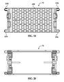
- FIG. 6 is a schematic of a first frame member utilized in the battery cell assembly of FIG. 1 ;
- FIG. 7 is another schematic of the first frame member of FIG. 6 ;
- FIG. 8 is a top view of the first frame member of FIG. 6 ;
- FIG. 9 is an enlarged view of a portion of the first frame member of FIG. 6 ;
- FIG. 10 is a schematic of a second frame member utilized in the battery cell assembly of FIG. 1 ;
- FIG. 11 is another schematic of the second frame member of FIG. 10 ;
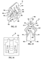
- FIG. 12 is a schematic of a metal trim clip member utilized in the battery cell assembly of FIG. 1 ;
- FIG. 13 is a side view of the metal trim clip member of FIG. 12 ;
- FIG. 14 is another side view of the metal trim clip member of FIG. 12 ;
- FIG. 15 is a schematic of a bottom endcap member utilized in the battery cell assembly of FIG. 1 ;
- FIG. 16 is a bottom view of the bottom endcap member of FIG. 15 ;
- FIG. 17 is a top view of the bottom endcap member of FIG. 15 ;
- FIG. 18 is a schematic of a top endcap member utilized in the battery cell assembly of FIG. 1 ;
- FIG. 19 is a bottom view of the top endcap member of FIG. 18 ;
- FIG. 20 is a bottom view of the top endcap member of FIG. 18 .
- the battery cell assembly 10 includes a first frame member 20 , a second frame member 22 , metal trim clip members 30 , 32 , 34 , 36 , 40 , 42 , 44 , 46 , 50 , 52 , 54 , 56 , battery cells 60 , 62 , 64 , 66 , a bottom endcap member 70 , and a top endcap member 72 .
- An advantage of the battery cell assembly 10 is that the assembly 10 utilizes metal trim clip members which allow the first frame member 20 , the second frame member 22 , the bottom endcap member 70 , and the top endcap member 72 to be readily coupled together, and de-coupled from one another if necessary for repair or maintenance.
- first frame member 20 and the second frame member 22 are adapted to be coupled to one another and to hold the battery cells 60 , 62 therebetween. Further, the first frame member 20 and the bottom endcap member 70 are adapted to be coupled to one another and to hold the battery cell 64 therebetween. Finally, the second frame member 22 and the top endcap member 72 are adapted to be coupled to one another and to hold the battery cell 66 therebetween.
- the first frame member 20 includes a rectangular ring-shaped body 90 , coupler portions 130 , 132 , 134 , 136 , and a thermally conductive plate 140 .
- the rectangular ring-shaped body 90 and the coupler portions 130 , 132 , 134 , 136 are constructed of plastic.
- the thermally conductive plate 140 is constructed of a metal such as aluminum or steel for example.
- the rectangular ring-shaped body 90 includes side walls 150 , 152 , 154 , 156 .
- the side walls 150 , 152 extend substantially parallel to one another and are coupled to and between and to the side walls 154 , 156 .
- the side walls 154 , 156 extend substantially parallel to one another and are coupled to and between the side walls 150 , 152 .
- the rectangular ring-shaped body 90 includes a first end 160 and a second end 162 .
- the coupler portion 130 is configured to hold the metal trim clip member 30 thereon and to receive a portion of the metal trim clip member 40 therein.
- the coupler portion 130 is coupled to and extends outwardly from the first end 160 of the rectangular ring-shaped body 90 in a first direction.
- the coupler portion 130 is disposed adjacent to both the side wall 150 and the side wall 154 and extends outwardly from the side wall 150 at the first end 160 in the first direction.
- the first direction is substantially parallel to the side wall 154 .
- the coupler portion 130 includes substantially flat walls 180 , 182 , peripheral wall portions 184 , 186 , 188 , 190 , and a tab member 194 .
- the peripheral wall portions 184 , 186 extend in a second direction from the substantially flat wall 180 substantially perpendicular to the substantially flat wall 180 .
- the tab member 194 extends in the second direction from the substantially flat wall 180 substantially perpendicular to the substantially flat wall 180 and is disposed between the peripheral wall portions 184 , 186 .
- the tab member 194 has an I-shaped cross-sectional profile for holding the metal trim clip member 30 thereon.
- the peripheral wall portions 188 , 190 extend in a third direction from the substantially flat wall 180 substantially perpendicular to the substantially flat wall 180 .
- the third direction is opposite to the second direction.
- the substantially flat wall 182 is coupled to and between the peripheral wall portions 188 , 190 and is spaced apart from the substantially flat wall 180 .
- the substantially flat wall 182 includes an aperture 200 extending therethrough that is sized and shaped to receive an endcap tab member 1194 of the bottom endcap member 70 and a portion of the metal trim clip member 40 therethrough.
- the substantially flat wall 182 further includes an inner surface 212 disposed proximate to the aperture 200 .
- the peripheral wall portions 188 , 190 and the substantially flat walls 180 , 182 define an interior region 210 therebetween that communicates with the aperture 200 .
- the coupler portion 132 is configured to hold the metal trim clip member 32 thereon and to receive a portion of the metal trim clip member 42 therein.
- the coupler portion 132 is coupled to and extends outwardly from the first end 160 of the rectangular ring-shaped body 90 in the first direction.
- the coupler portion 132 is disposed adjacent to both the side wall 150 and the side wall 156 and extends outwardly from the side wall 150 at the first end 160 in the first direction.
- the first direction is substantially parallel to the side wall 156 .
- the coupler portion 132 includes substantially flat walls 230 , 232 , peripheral wall portions 234 , 236 , 238 , 240 , and a tab member 244 .
- the peripheral wall portions 234 , 236 extend in the second direction from the substantially flat wall 230 substantially perpendicular to the substantially flat wall 230 .
- the tab member 244 extends in the second direction from the substantially flat wall 230 substantially perpendicular to the substantially flat wall 230 and is disposed between the peripheral wall portions 234 , 236 .
- the tab member 244 has an I-shaped cross-sectional profile for holding the metal trim clip member 32 thereon.
- the peripheral wall portions 238 , 240 extend in the third direction from the substantially flat wall 230 substantially perpendicular to the substantially flat wall 230 .
- the third direction is opposite to the second direction.
- the substantially flat wall 232 is coupled to and between the peripheral wall portions 238 , 240 and is spaced apart from the substantially flat wall 230 .
- the substantially flat wall 232 includes an aperture 250 extending therethrough that is sized and shaped to receive an endcap tab member 1244 of the bottom endcap member 70 and a portion of the metal trim clip member 42 therethrough.
- the substantially flat wall 232 further includes an inner surface 262 disposed proximate to the aperture 250 .
- the peripheral wall portions 238 , 240 and the substantially flat walls 230 , 232 define an interior region 260 therebetween that communicates with the aperture 250 .
- the coupler portion 134 is configured to hold the metal trim clip member 34 thereon and to receive a portion of the metal trim clip member 44 therein.
- the coupler portion 134 is coupled to and extends outwardly from the second end 162 of the rectangular ring-shaped body 90 in a fourth direction.
- the fourth direction is substantially parallel to the side wall 154 and opposite to the first direction.
- the coupler portion 134 is disposed adjacent to both the side wall 152 and the side wall 154 and extends outwardly from the side wall 152 at the second end 162 in the fourth direction.
- the coupler portion 134 includes substantially flat walls 280 , 282 , peripheral wall portions 284 , 286 , 288 , 290 , and a tab member 294 .
- the peripheral wall portions 284 , 286 extend in the second direction from the substantially flat wall 280 substantially perpendicular to the substantially flat wall 280 .
- the tab member 294 extends in the second direction from the substantially flat wall 280 substantially perpendicular to the substantially flat wall 280 and is disposed between the peripheral wall portions 284 , 286 .
- the tab member 294 has an I-shaped cross-sectional profile for holding the metal trim clip member 34 thereon.
- the peripheral wall portions 288 , 290 extend in the third direction from the substantially flat wall 280 substantially perpendicular to the substantially flat wall 280 .
- the substantially flat wall 282 is coupled to and between the peripheral wall portions 288 , 290 and is spaced apart from the substantially flat wall 280 .
- the substantially flat wall 282 includes an aperture 300 extending therethrough that is sized and shaped to receive an endcap tab member 1294 of the bottom endcap member 70 and a portion of the metal trim clip member 44 therethrough.
- the substantially flat wall 282 further includes an inner surface 312 disposed proximate to the aperture 300 .
- the peripheral wall portions 288 , 290 and the substantially flat walls 280 , 282 define an interior region 310 therebetween that communicates with the aperture 300 .
- the coupler portion 136 is configured to hold the metal trim clip member 36 thereon and to receive a portion of the metal trim clip member 46 therein.
- the coupler portion 136 is coupled to and extends outwardly from the second end 162 of the rectangular ring-shaped body 90 in the fourth direction.
- the coupler portion 136 is disposed adjacent to both the side wall 152 and the side wall 156 and extends outwardly from the side wall 152 at the second end 162 in the fourth direction.
- the coupler portion 136 includes substantially flat walls 330 , 332 , peripheral wall portions 334 , 336 , 338 , 340 , and a tab member 344 .
- the peripheral wall portions 334 , 336 extend in the second direction from the substantially flat wall 330 substantially perpendicular to the substantially flat wall 330 .
- the tab member 344 extends in the second direction from the substantially flat wall 330 substantially perpendicular to the substantially flat wall 330 and is disposed between the peripheral wall portions 334 , 336 .
- the tab member 344 has an I-shaped cross-sectional profile for holding the metal trim clip member 36 thereon.
- the peripheral wall portions 338 , 340 extend in the third direction from the substantially flat wall 330 substantially perpendicular to the substantially flat wall 330 .
- the substantially flat wall 332 is coupled to and between the peripheral wall portions 338 , 340 and is spaced apart from the substantially flat wall 330 .
- the substantially flat wall 332 includes an aperture 350 extending therethrough that is sized and shaped to receive an endcap tab member 1344 of the bottom endcap member 70 and a portion of the metal trim clip member 46 therethrough.
- the substantially flat wall 332 further includes an inner surface 362 disposed proximate to the aperture 350 .
- the peripheral wall portions 338 , 340 and the substantially flat walls 330 , 332 define an interior region 360 therebetween that communicates with the aperture 350 .
- the thermally conductive plate 140 is provided to conduct heat energy away from the battery cells 60 , 64 .
- the thermally conductive plate 140 has a first plate portion 390 and a second plate portion 392 .
- the second plate portion 392 is coupled to an end of the first plate portion 390 and extends substantially perpendicular to the first plate portion 390 .
- An outer periphery of the first plate portion 390 is coupled to the side walls 150 , 152 , 154 , 156 of the rectangular ring-shaped body 90 .
- the first plate portion 390 is disposed against the battery cells 60 , 64 .
- a portion of the first plate portion 390 extends through the side wall 156 of the rectangular ring-shaped body 90 .
- the second plate portion 392 is disposed on an exterior surface of the side wall 156 of the rectangular ring-shaped body 90 .
- the second frame member 22 includes a rectangular ring-shaped body 490 , coupler portions 530 , 532 , 534 , 536 , and a thermally conductive plate 540 .
- the rectangular ring-shaped body 490 and the coupler portions 530 , 532 , 534 , 536 are constructed of plastic.
- the thermally conductive plate 540 is constructed of a metal such as aluminum or steel for example.
- the rectangular ring-shaped body 490 includes side walls 550 , 552 , 554 , 556 .
- the side walls 550 , 552 extend substantially parallel to one another and are coupled to and between and to the side walls 554 , 556 .
- the side walls 554 , 556 extend substantially parallel to one another and are coupled to and between the side walls 550 , 552 .
- the rectangular ring-shaped body 490 includes a first end 560 and a second end 562 .
- the coupler portion 530 is configured to hold the metal trim clip member 50 thereon and to receive a portion of the metal trim clip member 30 therein.
- the coupler portion 530 is coupled to and extends outwardly from the first end 560 of the rectangular ring-shaped body 490 in the first direction.
- the coupler portion 530 is disposed adjacent to both the side wall 550 and the side wall 554 and extends outwardly from the side wall 550 at the first end 560 in the first direction.
- the first direction is substantially parallel to the side wall 554 .
- the coupler portion 530 includes substantially flat walls 580 , 582 , peripheral wall portions 584 , 586 , 588 , 590 , and a tab member 594 .
- the peripheral wall portions 584 , 586 extend in the second direction from the substantially flat wall 580 substantially perpendicular to the substantially flat wall 580 .
- the tab member 594 extends in the second direction from the substantially flat wall 580 substantially perpendicular to the substantially flat wall 580 and is disposed between the peripheral wall portions 584 , 586 .
- the tab member 594 has an I-shaped cross-sectional profile for holding the metal trim clip member 50 thereon.
- the peripheral wall portions 588 , 590 extend in a third direction from the substantially flat wall 580 substantially perpendicular to the substantially flat wall 580 . The third direction is opposite to the second direction.
- the substantially flat wall 582 is coupled to and between the peripheral wall portions 588 , 590 and is spaced apart from the substantially flat wall 580 .
- the substantially flat wall 582 includes an aperture 600 extending therethrough that is sized and shaped to receive a tab member 194 of the first frame member 20 and a portion of the metal trim clip member 30 therethrough.
- the substantially flat wall 582 further includes an inner surface 612 disposed proximate to the aperture 600 .
- the peripheral wall portions 588 , 590 and the substantially flat walls 580 , 582 define an interior region 610 therebetween that communicates with the aperture 600 .
- the coupler portion 532 is configured to hold the metal trim clip member 52 thereon and to receive a portion of the metal trim clip member 32 therein.
- the coupler portion 532 is coupled to and extends outwardly from the first end 560 of the rectangular ring-shaped body 490 in the first direction.
- the coupler portion 532 is disposed adjacent to both the side wall 550 and the side wall 556 and extends outwardly from the side wall 550 at the first end 560 in the first direction.
- the first direction is substantially parallel to the side wall 556 .
- the coupler portion 532 includes substantially flat walls 630 , 632 , peripheral wall portions 634 , 636 , 638 , 640 , and a tab member 644 .
- the peripheral wall portions 634 , 636 extend in the second direction from the substantially flat wall 630 substantially perpendicular to the substantially flat wall 630 .
- the tab member 644 extends in the second direction from the substantially flat wall 630 substantially perpendicular to the substantially flat wall 630 and is disposed between the peripheral wall portions 634 , 636 .
- the tab member 644 has an I-shaped cross-sectional profile for holding the metal trim clip member 52 thereon.
- the peripheral wall portions 638 , 640 extend in the third direction from the substantially flat wall 630 substantially perpendicular to the substantially flat wall 630 .
- the third direction is opposite to the second direction.
- the substantially flat wall 632 is coupled to and between the peripheral wall portions 638 , 640 and is spaced apart from the substantially flat wall 630 .
- the substantially flat wall 632 includes an aperture 650 extending therethrough that is sized and shaped to receive a tab member 244 of the first frame member 20 and a portion of the metal trim clip member 32 therethrough.
- the substantially flat wall 632 further includes an inner surface 662 disposed proximate to the aperture 650 .
- the peripheral wall portions 638 , 640 and the substantially flat walls 630 , 632 define an interior region 660 therebetween that communicates with the aperture 650 .
- the coupler portion 534 is configured to hold the metal trim clip member 54 thereon and to receive a portion of the metal trim clip member 34 therein.
- the coupler portion 534 is coupled to and extends outwardly from the second end 562 of the rectangular ring-shaped body 490 in the fourth direction.
- the fourth direction is substantially parallel to the side wall 554 and opposite to the first direction.
- the coupler portion 534 is disposed adjacent to both the side wall 552 and the side wall 554 and extends outwardly from the side wall 552 at the second end 562 in the fourth direction.
- the coupler portion 534 includes substantially flat walls 680 , 682 , peripheral wall portions 684 , 686 , 688 , 690 , and a tab member 694 .
- the peripheral wall portions 684 , 686 extend in the second direction from the substantially flat wall 680 substantially perpendicular to the substantially flat wall 680 .
- the tab member 694 extends in the second direction from the substantially flat wall 680 substantially perpendicular to the substantially flat wall 680 and is disposed between the peripheral wall portions 684 , 686 .
- the tab member 694 has an I-shaped cross-sectional profile for holding the metal trim clip member 54 thereon.
- the peripheral wall portions 688 , 690 extend in the third direction from the substantially flat wall 680 substantially perpendicular to the substantially flat wall 680 .
- the substantially flat wall 682 is coupled to and between the peripheral wall portions 688 , 690 and is spaced apart from the substantially flat wall 680 .
- the substantially flat wall 682 includes an aperture 700 extending therethrough that is sized and shaped to receive a tab member 294 of the first frame member 20 and a portion of the metal trim clip member 34 therethrough.
- the substantially flat wall 682 further includes an inner surface 712 disposed proximate to the aperture 700 .
- the peripheral wall portions 688 , 690 and the substantially flat walls 680 , 682 define an interior region 710 therebetween that communicates with the aperture 700 .
- the coupler portion 536 is configured to hold the metal trim clip member 56 thereon and to receive a portion of the metal trim clip member 36 therein.
- the coupler portion 536 is coupled to and extends outwardly from the second end 562 of the rectangular ring-shaped body 490 in the fourth direction.
- the coupler portion 536 is disposed adjacent to both the side wall 552 and the side wall 556 and extends outwardly from the side wall 552 at the second end 562 in the fourth direction.
- the coupler portion 536 includes substantially flat walls 730 , 732 , peripheral wall portions 734 , 736 , 738 , 740 , and a tab member 744 .
- the peripheral wall portions 734 , 736 extend in the second direction from the substantially flat wall 730 substantially perpendicular to the substantially flat wall 730 .
- the tab member 744 extends in the second direction from the substantially flat wall 730 substantially perpendicular to the substantially flat wall 730 and is disposed between the peripheral wall portions 734 , 736 .
- the tab member 744 has an I-shaped cross-sectional profile for holding the metal trim clip member 56 thereon.
- the peripheral wall portions 738 , 740 extend in the third direction from the substantially flat wall 730 substantially perpendicular to the substantially flat wall 730 .
- the substantially flat wall 732 is coupled to and between the peripheral wall portions 738 , 740 and is spaced apart from the substantially flat wall 730 .
- the substantially flat wall 732 includes an aperture 750 extending therethrough that is sized and shaped to receive a tab member 344 of the first frame member 20 and a portion of the metal trim clip member 36 therethrough.
- the substantially flat wall 732 further includes an inner surface 762 disposed proximate to the aperture 750 .
- the peripheral wall portions 738 , 740 and the substantially flat walls 730 , 732 define an interior region 760 therebetween that communicates with the aperture 750 .
- the thermally conductive plate 540 is provided to conduct heat energy away from the battery cells 62 , 66 .
- the thermally conductive plate 540 has a first plate portion 790 and a second plate portion 792 .
- the second plate portion 792 is coupled to an end of the first plate portion 790 and extends substantially perpendicular to the first plate portion 790 .
- An outer periphery of the first plate portion 790 is coupled to the side walls 550 , 552 , 554 , 556 of the rectangular ring-shaped body 490 .
- the first plate portion 790 is disposed against and between the battery cells 62 , 66 .
- a portion of the first plate portion 790 extends through the side wall 556 of the rectangular ring-shaped body 490 .
- the second plate portion 792 is disposed on an exterior surface of the side wall 556 of the rectangular ring-shaped body 490 .
- the metal trim clip members 30 , 32 , 34 , 36 are provided to couple the first frame member 20 to the second frame member 22 . Since the structure of the metal trim clip members are identical to one another, only the structure of the metal trim clip member 30 will be discussed in greater detail below.
- the metal trim clip member 30 is centered about a central plane 960 and having first and second wall portions 810 , 812 .
- the first wall portion 810 has first and second ends 820 , 822 .
- the second wall portion 810 has first and second ends 920 , 922 .
- the first end 820 of the first wall portion 810 is integrally coupled to the first end 920 of the second wall portion 812 .
- the first and second wall portions 810 , 812 define a gap 952 between the second end 822 of the first wall portion 810 and the second end 922 of the second wall portion 812 .
- the first wall portion 810 includes an arcuate-shaped portion 826 , a straight portion 828 , a bent portion 830 , and a straight portion 832 .
- the straight portion 828 is coupled to and between the arcuate-shaped portion 826 and the bent portion 830 .
- An aperture 834 extends through portions of the arcuate-shaped portion 826 , the straight portion 828 , the bent portion 830 , and the straight portion 832 such that the first wall portion 810 defines trim tabs 840 , 842 , and a v-shaped biasing member 850 .
- the trim tabs 840 , 842 extend across a portion of the gap 952 toward the second wall portion 812 .
- the v-shaped biasing member 850 is disposed between the trim tabs 840 , 842 and has an apex pointing away from the second wall portion 812 .
- the second wall portion 812 includes an arcuate-shaped portion 926 , a straight portion 928 , a bent portion 930 , and a straight portion 932 .
- the straight portion 928 is coupled to and between the arcuate-shaped portion 926 and the bent portion 930 .
- An aperture 934 extends through portions of the arcuate-shaped portion 926 , the straight portion 928 , the bent portion 930 , and the straight portion 932 such that the second wall portion 812 defines trim tabs 940 , 942 , and a v-shaped biasing member 950 .
- the trim tabs 940 , 942 extend across a portion of the gap 952 toward the first wall portion 810 .
- the v-shaped biasing member 950 is disposed between the trim tabs 940 , 942 and has an apex pointing away from the first wall portion 810 .
- the trim tabs 840 , 842 contact a first side of the tab member 194 of the coupler portion 130 of the first frame member 20 and the trim tabs 940 , 942 contact an opposite second side of the tab member 194 to hold the tab member 194 therebetween.
- the v-shaped biasing member 850 and the v-shaped biasing member 950 are adapted to contact and engage the inner surface 612 of the substantially flat wall 582 of the coupler portion 530 of the second frame member 22 in the interior region 610 to couple the second frame member 22 to the first frame member 20 .
- the metal trim clip member 32 is coupled to the tab member 244 of the coupler portion 132 , and the metal trim clip member 32 contacts and engages the inner surface 662 of the substantially flat wall 632 of the coupler portion 532 of the second frame member 22 in the interior region 660 to couple the second frame member 22 to the first frame member 20 .
- the metal trim clip member 34 is coupled to the tab member 294 of the coupler portion 134 , and the metal trim clip member 34 contacts and engages the inner surface 712 of the substantially flat wall 682 of the coupler portion 534 of the second frame member 22 in the interior region 710 to couple the second frame member 22 to the first frame member 20 .
- the metal trim clip member 36 is coupled to the tab member 344 of the coupler portion 136 , and the metal trim clip member 36 contacts and engages the inner surface 762 of the substantially flat wall 732 of the coupler portion 536 of the second frame member 22 in the interior region 760 to couple the second frame member 22 to the first frame member 20 .
- the battery cells 60 , 62 , 64 and 66 are each configured to generate an operational voltage.
- the battery cells 60 - 66 are pouch-type lithium-ion battery cells that have a substantially rectangular-shaped body portion and a pair of electrical terminals.
- the battery cells 60 - 66 are electrically coupled in series with one another.
- the structure of the battery cells 60 - 66 are identical to one another.
- the battery cell 60 includes a body portion 1000 and electrical terminals 1002 , 1004 extending outwardly from first and second ends, respectively, of the body portion 1000 .
- the battery cell 62 includes a body portion 1010 and electrical terminals 1012 , 1014 extending outwardly from first and second ends, respectively, of the body portion 1010 .
- the battery cell 64 includes a body portion 1020 and electrical terminals 1022 , 1024 extending outwardly from first and second ends, respectively, of the body portion 1020 .
- the battery cell 66 includes a body portion 1030 and electrical terminals 1032 , 1034 extending outwardly from first and second ends, respectively, of the body portion 1030 .
- the bottom endcap member 70 includes a rectangular body 1090 , coupler portions 1130 , 1132 , 1134 and 1136 .
- the rectangular body 1090 and the coupler portions 1130 , 1132 , 1134 , 1136 are constructed of plastic.
- the rectangular body 1090 includes a first end 1160 and a second end 1162 .
- the endcap coupler portion 1130 is configured to hold the metal trim clip member 40 thereon.
- the endcap coupler portion 1130 is coupled to and extends outwardly from the first end 1160 of the rectangular body 1090 in the first direction.
- the endcap coupler portion 1130 includes a substantially flat wall 1180 , peripheral wall portions 1184 , 1186 , and an endcap tab member 1194 .
- the peripheral wall portions 1184 , 1186 extend in the second direction from the substantially flat wall 1180 substantially perpendicular to the substantially flat wall 1180 .
- the tab member 1194 extends in the second direction from the substantially flat wall 1180 substantially perpendicular to the substantially flat wall 1180 and is disposed between the peripheral wall portions 1184 , 1186 .
- the tab member 1194 has an I-shaped cross-sectional profile for holding the metal trim clip member 40 thereon.
- the endcap coupler portion 1132 is configured to hold the metal trim clip member 42 thereon.
- the endcap coupler portion 1132 is coupled to and extends outwardly from the first end 1160 of the rectangular body 1090 in the first direction.
- the endcap coupler portion 1132 includes a substantially flat wall 1230 , peripheral wall portions 1234 , 1236 , and an endcap tab member 1244 .
- the peripheral wall portions 1234 , 1236 extend in the second direction from the substantially flat wall 1230 substantially perpendicular to the substantially flat wall 1230 .
- the endcap tab member 1244 extends in the second direction from the substantially flat wall 1230 substantially perpendicular to the substantially flat wall 1230 and is disposed between the peripheral wall portions 1234 , 1236 .
- the tab member 1244 has an I-shaped cross-sectional profile for holding the metal trim clip member 42 thereon.
- the endcap coupler portion 1134 is configured to hold the metal trim clip member 44 thereon.
- the endcap coupler portion 1134 is coupled to and extends outwardly from the second end 1162 of the rectangular body 1090 in a fourth direction.
- the fourth direction is substantially parallel to the side wall 154 and opposite to the first direction.
- the endcap coupler portion 1134 includes a substantially flat wall 1280 , peripheral wall portions 1284 , 1286 , and an endcap tab member 1294 .
- the peripheral wall portions 1284 , 1286 extend in the second direction from the substantially flat wall 1280 substantially perpendicular to the substantially flat wall 1280 .
- the endcap tab member 1294 extends in the second direction from the substantially flat wall 1280 substantially perpendicular to the substantially flat wall 1280 and is disposed between the peripheral wall portions 1284 , 1286 .
- the endcap tab member 1294 has an I-shaped cross-sectional profile for holding the metal trim clip member 44 thereon.
- the endcap coupler portion 1136 is configured to hold the metal trim clip member 46 thereon.
- the endcap portion 1136 is coupled to and extends outwardly from the second end 1162 of the rectangular body 1090 in the fourth direction.
- the endcap coupler portion 1136 includes a substantially flat walls 1330 , peripheral wall portions 1334 , 1336 , and an endcap tab member 1344 .
- the peripheral wall portions 1334 , 1336 extend in the second direction from the substantially flat wall 1330 substantially perpendicular to the substantially flat wall 1330 .
- the endcap tab member 1344 extends in the second direction from the substantially flat wall 1330 substantially perpendicular to the substantially flat wall 1330 and is disposed between the peripheral wall portions 1334 , 1336 .
- the endcap tab member 1344 has an I-shaped cross-sectional profile for holding the metal trim clip member 46 thereon.
- the metal trim clip member 40 is coupled to the endcap tab member 1194 of the endcap coupler portion 1130 , and the metal trim clip member 40 contacts and engages the inner surface 212 of the substantially flat wall 182 of the coupler portion 130 of the first frame member 20 in the interior region 210 to couple the bottom endcap member 70 to the first frame member 20 .
- the metal trim clip member 42 is coupled to the endcap tab member 1244 of the endcap coupler portion 1132 , and the metal trim clip member 42 contacts and engages the inner surface 262 of the substantially flat wall 232 of the coupler portion 132 of the first frame member 20 in the interior region 260 to couple the bottom endcap member 70 to the first frame member 20 .
- the metal trim clip member 44 is coupled to the endcap tab member 1294 of the endcap coupler portion 1134 , and the metal trim clip member 44 contacts and engages the inner surface 312 of the substantially flat wall 282 of the coupler portion 134 of the first frame member 20 in the interior region 310 to couple the bottom endcap member 70 to the first frame member 20 .
- the metal trim clip member 46 is coupled to the endcap tab member 1344 of the endcap coupler portion 1136 , and the metal trim clip member 46 contacts and engages the inner surface 362 of the substantially flat wall 332 of the coupler portion 136 of the first frame member 20 in the interior region 360 to couple the bottom endcap member 70 to the first frame member 20 .
- the top endcap member 70 includes a rectangular body 1490 , coupler portions 1530 , 1532 , 1534 and 1536 .
- the rectangular body 1490 and the coupler portions 1530 , 1532 , 1534 , 1536 are constructed of plastic.
- the rectangular body 1490 includes a first end 1560 and a second end 1562 .
- the endcap coupler portion 1530 is configured to receive the metal trim clip member 50 therein.
- the endcap coupler portion 1530 is coupled to and extends outwardly from the first end 1560 of the rectangular body 1490 in the first direction.
- the endcap coupler portion 1130 includes a substantially flat wall 1580 and a rectangular-ring-shaped wall 1582 disposed on and coupled to the substantially flat wall 1580 .
- the substantially flat wall 1580 has an inner surface 1585 , and an aperture 1584 extending through the wall 1580 .
- the substantially flat wall 1580 and the rectangular ring-shaped wall 1582 define an interior region 1586 that communicates with the aperture 1584 .
- the endcap coupler portion 1532 is configured to receive the metal trim clip member 52 therein.
- the endcap coupler portion 1532 is coupled to and extends outwardly from the first end 1560 of the rectangular body 1490 in the first direction.
- the endcap coupler portion 1532 includes a substantially flat wall 1590 and a rectangular-ring-shaped wall 1592 disposed on and coupled to the substantially flat wall 1590 .
- the substantially flat wall 1590 has an inner surface 1595 , and an aperture 1594 extending through the wall 1590 .
- the substantially flat wall 1590 and the rectangular ring-shaped wall 1592 define an interior region 1596 that communicates with the aperture 1594 .
- the endcap coupler portion 1534 is configured to receive the metal trim clip member 54 therein.
- the endcap coupler portion 1534 is coupled to and extends outwardly from the second end 1562 of the rectangular body 1490 in the second direction.
- the endcap coupler portion 1534 includes a substantially flat wall 1600 and a rectangular-ring-shaped wall 1602 disposed on and coupled to the substantially flat wall 1600 .
- the substantially flat wall 1600 has an inner surface 1605 , and an aperture 1604 extending through the wall 1600 .
- the substantially flat wall 1600 and the rectangular ring-shaped wall 1602 define an interior region 1606 that communicates with the aperture 1604 .
- the endcap coupler portion 1536 is configured to receive the metal trim clip member 56 therein.
- the endcap coupler portion 1536 is coupled to and extends outwardly from the second end 1562 of the rectangular body 1490 in the second direction.
- the endcap coupler portion 1536 includes a substantially flat wall 1610 and a rectangular-ring-shaped wall 1612 disposed on and coupled to the substantially flat wall 1610 .
- the substantially flat wall 1610 has an inner surface 1615 , and an aperture 1614 extending through the wall 1610 .
- the substantially flat wall 1610 and the rectangular ring-shaped wall 1612 define an interior region 1616 that communicates with the aperture 1614 .
- the metal trim clip member 50 is coupled to the tab member 594 of the coupler portion 530 of the second frame member 22 , and the metal trim clip member 50 contacts and engages the inner surface 1585 of the substantially flat wall 1580 of the endcap coupler portion 1530 of the top endcap member 72 in the interior region 1586 to couple the top endcap member 72 to the second frame member 22 .
- the metal trim clip member 52 is coupled to the tab member 644 of the coupler portion 532 of the second frame member 22 , and the metal trim clip member 52 contacts and engages the inner surface 1595 of the substantially flat wall 1590 of the endcap coupler portion 1532 of the top endcap member 72 in the interior region 1596 to couple the top endcap member 72 to the second frame member 22 .
- the metal trim clip member 54 is coupled to the tab member 694 of the coupler portion 534 of the second frame member 22 , and the metal trim clip member 54 contacts and engages the inner surface 1605 of the substantially flat wall 1600 of the endcap coupler portion 1534 of the top endcap member 72 in the interior region 1606 to couple the top endcap member 72 to the second frame member 22 .
- the metal trim clip member 56 is coupled to the tab member 744 of the coupler portion 536 of the second frame member 22 , and the metal trim clip member 56 contacts and engages the inner surface 1615 of the substantially flat wall 1610 of the endcap coupler portion 1536 of the top endcap member 72 in the interior region 1616 to couple the top endcap member 72 to the second frame member 22 .
- the battery cell assembly provides a substantial advantage over other battery cell assemblies.
- the battery cell assembly utilizes metal trim clip members which allow the first and second frame members to be readily coupled together, and de-coupled from one another if necessary for repair or maintenance, without breaking the first and second frame members.
Abstract
Description
Claims (10)
Priority Applications (2)
| Application Number | Priority Date | Filing Date | Title |
|---|---|---|---|
| US14/511,389 US9484559B2 (en) | 2014-10-10 | 2014-10-10 | Battery cell assembly |
| KR1020150046819A KR101717173B1 (en) | 2014-10-10 | 2015-04-02 | Battery cell assembly comprising frame member |
Applications Claiming Priority (1)
| Application Number | Priority Date | Filing Date | Title |
|---|---|---|---|
| US14/511,389 US9484559B2 (en) | 2014-10-10 | 2014-10-10 | Battery cell assembly |
Publications (2)
| Publication Number | Publication Date |
|---|---|
| US20160104874A1 US20160104874A1 (en) | 2016-04-14 |
| US9484559B2 true US9484559B2 (en) | 2016-11-01 |
Family
ID=55656061
Family Applications (1)
| Application Number | Title | Priority Date | Filing Date |
|---|---|---|---|
| US14/511,389 Active 2035-07-08 US9484559B2 (en) | 2014-10-10 | 2014-10-10 | Battery cell assembly |
Country Status (2)
| Country | Link |
|---|---|
| US (1) | US9484559B2 (en) |
| KR (1) | KR101717173B1 (en) |
Families Citing this family (6)
| Publication number | Priority date | Publication date | Assignee | Title |
|---|---|---|---|---|
| US10770762B2 (en) | 2014-05-09 | 2020-09-08 | Lg Chem, Ltd. | Battery module and method of assembling the battery module |
| US10084218B2 (en) | 2014-05-09 | 2018-09-25 | Lg Chem, Ltd. | Battery pack and method of assembling the battery pack |
| JP1533400S (en) * | 2014-10-24 | 2015-09-14 | ||
| JP1524274S (en) * | 2014-10-24 | 2015-05-25 | ||
| US9755198B2 (en) * | 2015-10-07 | 2017-09-05 | Lg Chem, Ltd. | Battery cell assembly |
| ES2953761A1 (en) * | 2022-04-08 | 2023-11-15 | Renova540 Sl | PLASTIC RING FOR PROTECTION OF CONSTRUCTION GAPS (Machine-translation by Google Translate, not legally binding) |
Citations (175)
| Publication number | Priority date | Publication date | Assignee | Title |
|---|---|---|---|---|
| US1587425A (en) | 1923-06-18 | 1926-06-01 | Schepp Otto | Cooling accumulator cell |
| GB481891A (en) | 1936-09-18 | 1938-03-18 | India Rubber Gutta Percha Tele | Improvements in or relating to containers for electric storage cells |
| US2273244A (en) | 1940-04-03 | 1942-02-17 | Electric Storage Battery Co | Storage battery cell |
| US2391859A (en) | 1931-11-07 | 1946-01-01 | Hoover Co | Room cooling device |
| US3503558A (en) | 1968-03-14 | 1970-03-31 | Electrolux Corp | Exhaust diffusion manifold for a vacuum cleaner or the like |
| US3522100A (en) | 1966-12-19 | 1970-07-28 | Asea Ab | Fuel cell battery |
| US3550681A (en) | 1968-12-30 | 1970-12-29 | Gen Motors Corp | Self-adjusting thermal connector |
| US3964930A (en) | 1975-07-21 | 1976-06-22 | United Technologies Corporation | Fuel cell cooling system |
| US4009752A (en) | 1975-02-24 | 1977-03-01 | Honeywell Information Systems Inc. | Warp-resistant heat sink |
| US4063590A (en) | 1976-10-22 | 1977-12-20 | Mcconnell Christopher L | Preheater for clothes dryer |
| US4298904A (en) | 1979-12-17 | 1981-11-03 | The Boeing Company | Electronic conduction cooling clamp |
| US4305456A (en) | 1977-08-12 | 1981-12-15 | Paul Mueller Company | Condenser and hot water system |
| US4322776A (en) | 1980-08-04 | 1982-03-30 | Hughes Aircraft Company | Thermal interconnection |
| US4444994A (en) | 1982-01-29 | 1984-04-24 | Varo, Inc. | Electrically insulated quick disconnect heat sink |
| US4518663A (en) | 1983-07-01 | 1985-05-21 | Energy Development Associates, Inc. | Electrolyte circulation subsystem |
| US4646202A (en) | 1983-11-02 | 1987-02-24 | British Aerospace Plc | Cabinet for electronic apparatus |
| US4701829A (en) | 1985-04-16 | 1987-10-20 | Amphenol Corporation | Thermal connector for printed circuit card equipped with electronic components |
| US4777561A (en) | 1985-03-26 | 1988-10-11 | Hughes Aircraft Company | Electronic module with self-activated heat pipe |
| US4849858A (en) | 1986-10-20 | 1989-07-18 | Westinghouse Electric Corp. | Composite heat transfer means |
| US4982785A (en) | 1990-03-06 | 1991-01-08 | Inter-City Products Corporation (Usa) | Serpentine heat exchanger |
| US4995240A (en) | 1987-01-27 | 1991-02-26 | Eaton Corporation | Controlling refrigeration having control module directly attached on valve body |
| US5057968A (en) | 1989-10-16 | 1991-10-15 | Lockheed Corporation | Cooling system for electronic modules |
| US5071652A (en) | 1990-12-11 | 1991-12-10 | Globe-Union Inc. | Metal oxide hydrogen battery having improved heat transfer properties |
| US5186250A (en) | 1990-05-11 | 1993-02-16 | Showa Aluminum Kabushiki Kaisha | Tube for heat exchangers and a method for manufacturing the tube |
| US5214564A (en) | 1992-04-23 | 1993-05-25 | Sunstrand Corporation | Capacitor assembly with integral cooling apparatus |
| US5270131A (en) | 1990-12-11 | 1993-12-14 | Sulzer Brothers Limited | Module for a fuel cell battery |
| US5322745A (en) | 1992-11-10 | 1994-06-21 | Matsushita Electric Industrial Co., Ltd. | Storage battery system |
| US5329988A (en) | 1993-05-28 | 1994-07-19 | The Allen Group, Inc. | Heat exchanger |
| US5346786A (en) | 1994-03-21 | 1994-09-13 | Hodgetts Philip J | Modular rack mounted battery system |
| US5356735A (en) | 1993-05-10 | 1994-10-18 | General Motors Corporation | Heated/cooled battery |
| US5443926A (en) | 1992-11-02 | 1995-08-22 | Compagnie Europeenne D'accumulateurs | Thermoregulated battery of accumulators, especially for an electric vehicle |
| US5510203A (en) | 1994-02-23 | 1996-04-23 | Matsushita Electric Industrial Co., Ltd. | Cell and module battery of sealed alkaline storage battery |
| JPH08111244A (en) | 1994-10-12 | 1996-04-30 | Nissan Motor Co Ltd | Layer-built battery device |
| US5520976A (en) | 1993-06-30 | 1996-05-28 | Simmonds Precision Products Inc. | Composite enclosure for electronic hardware |
| JPH09129213A (en) | 1995-11-06 | 1997-05-16 | Toshiba Battery Co Ltd | Manufacture of battery |
| JPH09219213A (en) | 1996-02-09 | 1997-08-19 | Nissan Motor Co Ltd | Secondary battery for electric vehicle and temperature rise alleviation device therefor |
| US5663007A (en) | 1994-02-23 | 1997-09-02 | Matsushita Electric Industrial Co., Ltd. | Sealed storage battery and method for manufacturing the same |
| US5736836A (en) | 1996-04-10 | 1998-04-07 | Honda Giken Kogyo Kabushiki Kaisha | Battery discharge gas control system |
| US5756227A (en) | 1994-11-18 | 1998-05-26 | Honda Giken Kogyo Kabushiki Kaisha | Battery assembly with temperature control mechanism |
| US5937664A (en) | 1997-03-05 | 1999-08-17 | Toyota Jidosha Kabushiki Kaisha | Battery cooling system for vehicle |
| US5985483A (en) | 1998-01-29 | 1999-11-16 | Alcatel | Sealed battery block provided with a cooling system |
| US6087036A (en) | 1997-07-25 | 2000-07-11 | 3M Innovative Properties Company | Thermal management system and method for a solid-state energy storing device |
| US6111387A (en) | 1997-03-24 | 2000-08-29 | Matsushita Electric Industrial Co., Ltd. | End plate incorporated in battery power source unit, and cooling device for same |
| US6176095B1 (en) | 1999-01-19 | 2001-01-23 | Carrier Corporation | Pretrip device for testing of a refrigeration system compressor |
| JP2001105843A (en) | 1999-10-12 | 2001-04-17 | Nippon Soken Inc | Battery cooling device |
| US6289979B1 (en) | 1997-12-08 | 2001-09-18 | Zexel Corporation | Heat exchanger |
| US6344728B1 (en) | 1997-10-06 | 2002-02-05 | Matsushita Electric Industrial Co., Ltd. | Battery power source supply with coolant flow |
| JP2002038033A (en) | 2000-05-19 | 2002-02-06 | Suzuki Sogyo Co Ltd | Thermally conductive sheet |
| US6362598B2 (en) | 2000-04-29 | 2002-03-26 | Vb Autobatterie Gmbh | Method for determining the state of charge and loading capacity of an electrical storage battery |
| US6399238B1 (en) | 1999-12-13 | 2002-06-04 | Alcatel | Module configuration |
| US6422027B1 (en) | 2001-05-03 | 2002-07-23 | Ford Global Tech., Inc. | System and method for cooling a battery pack |
| US6448741B1 (en) | 1998-09-03 | 2002-09-10 | Matsushita Electric Industrial Co., Ltd. | Temperature control method and structure for a battery pack |
| US6462949B1 (en) | 2000-08-07 | 2002-10-08 | Thermotek, Inc. | Electronic enclosure cooling system |
| JP2002319383A (en) | 2001-04-23 | 2002-10-31 | Toyota Motor Corp | Battery module |
| JP2002333255A (en) | 2002-03-29 | 2002-11-22 | Sanyo Electric Co Ltd | Cryogenic refrigerator |
| US20020182493A1 (en) | 1993-10-25 | 2002-12-05 | Ovshinsky Stanford R. | Mechanical and thermal improvements in metal hydride batteries, battery modules and battery packs |
| US6512347B1 (en) | 2001-10-18 | 2003-01-28 | General Motors Corporation | Battery having an integral cooling system |
| US20030080714A1 (en) | 2001-10-29 | 2003-05-01 | Yoshimitsu Inoue | Battery temperature control device for controlling the temperature of battery installed in vehicle |
| US6569556B2 (en) | 2001-01-29 | 2003-05-27 | General Motors Corporation | Cooling system for a battery pack |
| JP2003188323A (en) | 2001-12-19 | 2003-07-04 | Sony Corp | Graphite sheet and its manufacturing method |
| DE19639115C2 (en) | 1996-09-24 | 2003-08-07 | Behr Gmbh & Co | Plate-shaped heat transfer element |
| JP2003282112A (en) | 2002-03-26 | 2003-10-03 | Denso Corp | Intermediate heat exchanger for fuel cell |
| US20030211384A1 (en) | 2002-05-13 | 2003-11-13 | Matsushita Electric Industrial Co., Ltd. | Cooling device for battery pack and rechargeable battery |
| US6662891B2 (en) | 2000-04-13 | 2003-12-16 | Toyota Jidosha Kabushiki Kaisha | Vehicle power source device wherein cooling air is introduced into battery casing through opening formed through vehicle floor |
| US6689510B1 (en) | 1998-08-23 | 2004-02-10 | Ovonic Battery Company, Inc. | Monoblock battery assembly with cross-flow cooling |
| US6696197B2 (en) | 2000-09-29 | 2004-02-24 | Kabushiki Kaisha Toshiba | Battery pack and portable electronic appliance |
| US20040069474A1 (en) | 2002-07-05 | 2004-04-15 | Alan Wu | Baffled surface cooled heat exchanger |
| US6724172B2 (en) | 2002-06-26 | 2004-04-20 | Hyundai Motor Company | Method for determining a maximum charge current and a maximum discharge current of a battery |
| US6775998B2 (en) | 2000-11-10 | 2004-08-17 | Matsushita Refrigeration Company | Freezer and refrigerator provided with freezer |
| US6780538B2 (en) | 1999-07-22 | 2004-08-24 | Matsushita Electric Industrial Co., Ltd. | Battery module, and rechargeable battery for constituting the battery module |
| US6821671B2 (en) | 2002-03-01 | 2004-11-23 | Lg Chem, Ltd. | Method and apparatus for cooling and positioning prismatic battery cells |
| JP2004333115A (en) | 2003-04-16 | 2004-11-25 | Showa Denko Kk | Heat exchanger, and method for manufacturing the same |
| US6826948B1 (en) | 2003-10-09 | 2004-12-07 | Delphi Technologies, Inc. | Leak detection apparatus for a liquid circulation cooling system |
| US20050026014A1 (en) | 2003-07-31 | 2005-02-03 | Michael Fogaing | Polymer batteries having thermal exchange apparatus |
| US20050089750A1 (en) | 2002-02-19 | 2005-04-28 | Chin-Yee Ng | Temperature control apparatus and method for high energy electrochemical cells |
| US20050103486A1 (en) | 2001-12-21 | 2005-05-19 | Behr Gmbh & Co., Kg | Heat exchanger, particularly for a motor vehicle |
| JP2005126315A (en) | 2003-09-30 | 2005-05-19 | Hitachi Ltd | Hydrogen storage and supply device, its system, and distributed power and car using the same |
| US20050110460A1 (en) | 2003-10-21 | 2005-05-26 | Juichi Arai | Battery module having lithium battery, and vehicle control system employing battery module having lithium battery |
| JP2005147443A (en) | 2003-11-12 | 2005-06-09 | Calsonic Kansei Corp | Laminated type heat exchanger |
| US20050134038A1 (en) | 2003-12-17 | 2005-06-23 | Eaton Corporation | Fitting for fluid conveyance |
| EP1577966A2 (en) | 2004-03-18 | 2005-09-21 | Fuji Jukogyo Kabushiki Kaisha | Accumulator device |
| KR20050092605A (en) | 2004-03-16 | 2005-09-22 | 주식회사 엘지화학 | Secondary battery having a high safety |
| JP2005349955A (en) | 2004-06-10 | 2005-12-22 | Toyota Motor Corp | Cooling structure for power storage mechanism |
| US6982131B1 (en) | 1999-10-08 | 2006-01-03 | Matsushita Electric Industrial Co., Ltd. | Structure for electrode terminals of battery module |
| JP2006139928A (en) | 2004-11-10 | 2006-06-01 | Nissan Motor Co Ltd | Battery system |
| US7070874B2 (en) | 2002-12-24 | 2006-07-04 | Fuelcell Energy, Inc. | Fuel cell end unit with integrated heat exchanger |
| WO2006101343A1 (en) | 2005-03-23 | 2006-09-28 | Sk Energy Co., Ltd. | Structure of layering unit cells for high power lithium polymer battery |
| US20060234119A1 (en) | 2005-04-14 | 2006-10-19 | Kruger Duane D | Apparatus and method for securing battery cell packs |
| KR100637472B1 (en) | 2004-12-07 | 2006-10-23 | 삼성에스디아이 주식회사 | Secondary battery module |
| US7143724B2 (en) | 2004-08-16 | 2006-12-05 | Sanyo Electric Co., Ltd. | Power supply device for vehicle |
| US20060286450A1 (en) | 2005-06-03 | 2006-12-21 | Junill Yoon | Secondary battery of novel structure and battery pack having the same |
| WO2007007503A1 (en) | 2005-07-12 | 2007-01-18 | Toyota Jidosha Kabushiki Kaisha | Structure of hybrid vehicle |
| US20070062681A1 (en) | 2005-09-19 | 2007-03-22 | Stephen Beech | Flanged connection for heat exchanger |
| US20070087266A1 (en) | 2005-10-18 | 2007-04-19 | Debbi Bourke | Modular battery system |
| US7250741B2 (en) | 2003-08-13 | 2007-07-31 | Hyundai Motor Company | Method and system for calculating available power of a battery |
| US7264902B2 (en) | 2001-07-04 | 2007-09-04 | Nissan Motor Co., Ltd. | Battery system with excellent controllability for temperature |
| US20070227166A1 (en) | 2003-12-22 | 2007-10-04 | General Electric Company | Methods and apparatus for controlling refrigerators |
| US7278389B2 (en) | 2005-04-19 | 2007-10-09 | Murat Kirakosyan | Automobile intake air flow plenum and plenum diverter |
| KR100765659B1 (en) | 2005-08-09 | 2007-10-10 | 현대자동차주식회사 | Fuel cell-stack structure for automobile |
| WO2007115743A2 (en) | 2006-04-04 | 2007-10-18 | Daimler Ag | Heat exchanger comprising deep-drawn, integrally formed distribution and collecting channels for heat-exchanger module plates comprising a tempering medium |
| EP1852925A1 (en) | 2005-02-25 | 2007-11-07 | Toyota Jidosha Kabushiki Kaisha | Battery pack |
| JP2007305425A (en) | 2006-05-11 | 2007-11-22 | Toyota Motor Corp | Battery pack and vehicle |
| US20080003491A1 (en) | 2003-10-03 | 2008-01-03 | Yahnker Christopher R | Thermal management systems for battery packs |
| US20080041079A1 (en) | 2006-06-26 | 2008-02-21 | Denso Corporation | Refrigerant cycle device with ejector |
| JP2008054379A (en) | 2006-08-22 | 2008-03-06 | Calsonic Kansei Corp | Battery cooling system for vehicle |
| JP2008062875A (en) | 2006-09-11 | 2008-03-21 | Calsonic Kansei Corp | Battery cooling system for vehicle |
| JP2008080995A (en) | 2006-09-28 | 2008-04-10 | Denso Corp | Cooling system |
| US20080110189A1 (en) | 2006-11-15 | 2008-05-15 | Glacier Bay. Inc. | Hvac system |
| KR20080047641A (en) | 2006-11-27 | 2008-05-30 | 주식회사 엘지화학 | Power supply system having heat radiation-preventing structure |
| JP2008159440A (en) | 2006-12-25 | 2008-07-10 | Calsonic Kansei Corp | Vehicular battery cooling system |
| US20080182151A1 (en) | 2007-01-25 | 2008-07-31 | Honda Motor Co., Ltd. | Fuel cell system |
| WO2008111162A1 (en) | 2007-03-13 | 2008-09-18 | Hoshizaki Denki Kabushiki Kaisha | Cooling storage chamber and method for operating the same |
| US20080248338A1 (en) | 2004-10-05 | 2008-10-09 | Masaya Yano | Fuel Cell and Power Generating Method |
| US20080299446A1 (en) | 2007-06-01 | 2008-12-04 | Cobasys. Llc | Coolant manifold |
| US7467525B1 (en) | 2005-08-23 | 2008-12-23 | Denso Corporation | Supercritical refrigeration cycle system |
| JP2009009889A (en) | 2007-06-29 | 2009-01-15 | Sanyo Electric Co Ltd | Power source device for vehicle |
| JP2009054297A (en) | 2007-08-23 | 2009-03-12 | Toshiba Corp | Battery pack |
| US20090074478A1 (en) | 2007-06-19 | 2009-03-19 | Konica Minolta Business Technologies, Inc. | Resin composition, molded component, electrophotographic transfer film and image-forming apparatus |
| US20090104512A1 (en) | 2007-01-30 | 2009-04-23 | Jochen Fassnacht | Device having at least one electrochemical cell |
| US7531270B2 (en) | 2006-10-13 | 2009-05-12 | Enerdel, Inc. | Battery pack with integral cooling and bussing devices |
| WO2009073225A1 (en) | 2007-12-05 | 2009-06-11 | Enerdel, Inc. | Battery assembly with temperature control device |
| US20090155680A1 (en) | 2005-03-16 | 2009-06-18 | Ford Global Technologies, Llc | Power supply system |
| US20090186265A1 (en) | 2008-01-18 | 2009-07-23 | Lg Chem, Ltd | Battery cell assembly and method for assembling the battery cell assembly |
| US7591303B2 (en) | 2002-04-29 | 2009-09-22 | Bergstrom, Inc. | Vehicle air conditioning and heating method providing engine on and engine off operation |
| KR100921346B1 (en) | 2006-09-25 | 2009-10-13 | 주식회사 엘지화학 | Mid-Large Battery Module and Battery Module Assembly |
| KR20090107443A (en) | 2008-04-08 | 2009-10-13 | 쏘씨에떼 드 베이뀔르 엘렉트리끄 | Electrical battery comprising flexible generating elements and a system for the mechanical and thermal conditioning of said elements |
| US20090258288A1 (en) | 2008-04-09 | 2009-10-15 | Gm Global Technology Operations, Inc. | Batteries and components thereof and methods of making and assembling the same |
| US20090258289A1 (en) | 2008-04-09 | 2009-10-15 | Gm Global Technology Operations, Inc. | Battery cooling plate design with discrete channels |
| US20090280395A1 (en) | 2008-05-09 | 2009-11-12 | Gm Global Technology Operations, Inc. | Battery Thermal System for Vehicle |
| US20090325052A1 (en) | 2008-06-30 | 2009-12-31 | Lg Chem, Ltd. | Battery Module Having Cooling Manifold and Method for Cooling Battery Module |
| US20090325051A1 (en) | 2008-06-30 | 2009-12-31 | Lg Chem, Ltd. | Battery Module Having a Rubber Cooling Manifold |
| US20090325055A1 (en) | 2008-06-30 | 2009-12-31 | Lg Chem, Ltd. | Battery module having cooling manifold with ported screws and method for cooling the battery module |
| US20090325054A1 (en) | 2008-06-30 | 2009-12-31 | Lg Chem, Ltd. | Battery Cell Assembly Having Heat Exchanger With Serpentine Flow Path |
| US20100112419A1 (en) | 2007-04-04 | 2010-05-06 | Soo Yeup Jang | Battery temperature controller for electric vehicle using thermoelectric semiconductor |
| US20100203376A1 (en) | 2007-03-21 | 2010-08-12 | Lg Chem, Ltd. | Middle or large-sized battery pack case providing improved distribution uniformity in coolant flux |
| US20100209760A1 (en) | 2007-05-10 | 2010-08-19 | Calsonic Kansei Corporation | Battery-cell module structure of battery |
| US7795845B2 (en) | 2005-03-25 | 2010-09-14 | Samsung Sdi Co., Ltd. | Rechargeable battery module having a cooling mechanism |
| US20100262791A1 (en) | 2002-08-29 | 2010-10-14 | Gilton Terry L | Software refreshed memory device and method |
| US7816029B2 (en) | 2006-08-31 | 2010-10-19 | Nissan Motor Co., Ltd. | Battery module |
| US20100275619A1 (en) | 2009-04-30 | 2010-11-04 | Lg Chem, Ltd. | Cooling system for a battery system and a method for cooling the battery system |
| US20100279152A1 (en) | 2009-04-30 | 2010-11-04 | Lg Chem, Ltd. | Battery systems, battery modules, and method for cooling a battery module |
| US20100276132A1 (en) | 2009-04-30 | 2010-11-04 | Lg Chem, Ltd. | Cooling manifold and method for manufacturing the cooling manifold |
| US20100279154A1 (en) | 2009-04-30 | 2010-11-04 | Lg Chem, Ltd. | Battery systems, battery modules, and method for cooling a battery module |
| US20100304203A1 (en) | 2007-11-07 | 2010-12-02 | Buck Derrick S | Battery assembly with temperature control device |
| US20100307723A1 (en) | 2007-11-13 | 2010-12-09 | Behr Gmbh & Co. Kg | Device for cooling a heat source of a motor vehicle |
| US20110000241A1 (en) | 2009-07-02 | 2011-01-06 | Ferrari S.P.A. | Electric traction vehicle with cooling by refrigeration cycle |
| US20110020676A1 (en) | 2008-03-24 | 2011-01-27 | Sanyo Electric Co., Ltd. | Battery device and battery unit |
| US7879480B2 (en) | 2004-12-24 | 2011-02-01 | Lg Chem, Ltd. | Battery cartridge for novel structure and open type battery module containing the same |
| US20110027640A1 (en) | 2009-07-29 | 2011-02-03 | Lg Chem, Ltd. | Battery module and method for cooling the battery module |
| US20110027631A1 (en) | 2007-09-21 | 2011-02-03 | Martin Holger Koenigsmann | Temperature-controlled battery device and method for it |
| US7883793B2 (en) | 2008-06-30 | 2011-02-08 | Lg Chem, Ltd. | Battery module having battery cell assemblies with alignment-coupling features |
| KR20110013270A (en) | 2009-07-29 | 2011-02-09 | 주식회사 엘지화학 | Battery module and method for cooling the battery module |
| US20110045326A1 (en) | 2008-02-27 | 2011-02-24 | Stephan Leuthner | Device and method for cooling a battery module |
| US20110041525A1 (en) | 2007-11-05 | 2011-02-24 | Lg Electronics Inc. | Control method of refrigerator |
| US20110052959A1 (en) | 2009-08-28 | 2011-03-03 | Lg Chem, Ltd. | Battery module and method for cooling the battery module |
| US7976978B2 (en) | 2006-10-23 | 2011-07-12 | Lg Chem, Ltd. | Member of connecting electrode in battery module |
| US7981538B2 (en) | 2005-08-10 | 2011-07-19 | Samsung Sdi Co., Ltd. | Battery module with improved cell barrier between unit cells |
| US20110189523A1 (en) | 2010-02-04 | 2011-08-04 | Kiyeol Eom | Cooling apparatus of a battery module |
| US8011467B2 (en) | 2003-03-28 | 2011-09-06 | Mitsubishi Denki Kabushiki Kaisha | Vehicle power supply system |
| US8030886B2 (en) | 2005-12-21 | 2011-10-04 | Nuventix, Inc. | Thermal management of batteries using synthetic jets |
| WO2011145830A2 (en) | 2010-05-18 | 2011-11-24 | 주식회사 엘지화학 | Compact cooling member having superior stability, and battery module comprising same |
| US8067111B2 (en) | 2008-06-30 | 2011-11-29 | Lg Chem, Ltd. | Battery module having battery cell assembly with heat exchanger |
| US20120082880A1 (en) | 2010-10-04 | 2012-04-05 | Lg Chem Ltd. | Battery cell assembly, heat exchanger, and method for manufacturing the heat exchanger |
| US20120171543A1 (en) | 2009-03-30 | 2012-07-05 | Stefan Hirsch | Device for the thermal connection of an energy storage |
| US8409743B2 (en) | 2007-11-28 | 2013-04-02 | Sanyo Electric Co., Ltd. | Battery system with battery cells arranged in array alignment |
| US20130136136A1 (en) | 2011-11-28 | 2013-05-30 | Fujitsu Limited | Apparatus and method for processing received data |
| US20130196205A1 (en) * | 2011-06-03 | 2013-08-01 | Enerdel, Inc. | Energy storage system |
| US20130255293A1 (en) | 2012-03-29 | 2013-10-03 | Lg Chem, Ltd. | Battery system and method for cooling the battery system |
| US20130309542A1 (en) | 2012-05-19 | 2013-11-21 | Lg Chem, Ltd. | Battery cell assembly and method for manufacturing a cooling fin for the battery cell assembly |
| US20140050966A1 (en) | 2012-08-16 | 2014-02-20 | Lg Chem, Ltd. | Battery module and method for assembling the battery module |
| US20140050953A1 (en) | 2012-08-16 | 2014-02-20 | Lg Chem, Ltd. | Battery module |
| US20140120390A1 (en) | 2012-10-31 | 2014-05-01 | Lg Chem, Ltd. | Battery cell assembly and method for manufacturing a cooling fin for the battery cell assembly |
| US20140147709A1 (en) | 2012-11-27 | 2014-05-29 | Satish Ketkar | Battery system and method for cooling a battery cell assembly |
| US20140227575A1 (en) | 2013-02-13 | 2014-08-14 | Lg Chem, Ltd. | Battery cell assembly and method for manufacturing the battery cell assembly |
| US20140308558A1 (en) | 2013-04-12 | 2014-10-16 | Lg Chem, Ltd. | Battery cell assembly and method for manufacturing a cooling fin for the battery cell assembly |
Family Cites Families (3)
| Publication number | Priority date | Publication date | Assignee | Title |
|---|---|---|---|---|
| KR101492019B1 (en) * | 2012-08-17 | 2015-02-11 | 주식회사 엘지화학 | Battery Module Having Venting Guiding Portion |
| KR101393436B1 (en) * | 2012-09-27 | 2014-05-13 | 주식회사 코캄 | Battery module and cell-cartridge |
| KR101426618B1 (en) * | 2012-12-13 | 2014-08-05 | 세방전지(주) | Battery module using assembly of insert type |
-
2014
- 2014-10-10 US US14/511,389 patent/US9484559B2/en active Active
-
2015
- 2015-04-02 KR KR1020150046819A patent/KR101717173B1/en active IP Right Grant
Patent Citations (193)
| Publication number | Priority date | Publication date | Assignee | Title |
|---|---|---|---|---|
| US1587425A (en) | 1923-06-18 | 1926-06-01 | Schepp Otto | Cooling accumulator cell |
| US2391859A (en) | 1931-11-07 | 1946-01-01 | Hoover Co | Room cooling device |
| GB481891A (en) | 1936-09-18 | 1938-03-18 | India Rubber Gutta Percha Tele | Improvements in or relating to containers for electric storage cells |
| US2273244A (en) | 1940-04-03 | 1942-02-17 | Electric Storage Battery Co | Storage battery cell |
| US3522100A (en) | 1966-12-19 | 1970-07-28 | Asea Ab | Fuel cell battery |
| US3503558A (en) | 1968-03-14 | 1970-03-31 | Electrolux Corp | Exhaust diffusion manifold for a vacuum cleaner or the like |
| US3550681A (en) | 1968-12-30 | 1970-12-29 | Gen Motors Corp | Self-adjusting thermal connector |
| US4009752A (en) | 1975-02-24 | 1977-03-01 | Honeywell Information Systems Inc. | Warp-resistant heat sink |
| US3964930A (en) | 1975-07-21 | 1976-06-22 | United Technologies Corporation | Fuel cell cooling system |
| US4063590A (en) | 1976-10-22 | 1977-12-20 | Mcconnell Christopher L | Preheater for clothes dryer |
| US4305456A (en) | 1977-08-12 | 1981-12-15 | Paul Mueller Company | Condenser and hot water system |
| US4298904A (en) | 1979-12-17 | 1981-11-03 | The Boeing Company | Electronic conduction cooling clamp |
| US4322776A (en) | 1980-08-04 | 1982-03-30 | Hughes Aircraft Company | Thermal interconnection |
| US4444994A (en) | 1982-01-29 | 1984-04-24 | Varo, Inc. | Electrically insulated quick disconnect heat sink |
| US4518663A (en) | 1983-07-01 | 1985-05-21 | Energy Development Associates, Inc. | Electrolyte circulation subsystem |
| US4646202A (en) | 1983-11-02 | 1987-02-24 | British Aerospace Plc | Cabinet for electronic apparatus |
| US4777561A (en) | 1985-03-26 | 1988-10-11 | Hughes Aircraft Company | Electronic module with self-activated heat pipe |
| US4701829A (en) | 1985-04-16 | 1987-10-20 | Amphenol Corporation | Thermal connector for printed circuit card equipped with electronic components |
| US4849858A (en) | 1986-10-20 | 1989-07-18 | Westinghouse Electric Corp. | Composite heat transfer means |
| US4995240A (en) | 1987-01-27 | 1991-02-26 | Eaton Corporation | Controlling refrigeration having control module directly attached on valve body |
| US5057968A (en) | 1989-10-16 | 1991-10-15 | Lockheed Corporation | Cooling system for electronic modules |
| US4982785A (en) | 1990-03-06 | 1991-01-08 | Inter-City Products Corporation (Usa) | Serpentine heat exchanger |
| US5186250A (en) | 1990-05-11 | 1993-02-16 | Showa Aluminum Kabushiki Kaisha | Tube for heat exchangers and a method for manufacturing the tube |
| US5270131A (en) | 1990-12-11 | 1993-12-14 | Sulzer Brothers Limited | Module for a fuel cell battery |
| US5071652A (en) | 1990-12-11 | 1991-12-10 | Globe-Union Inc. | Metal oxide hydrogen battery having improved heat transfer properties |
| US5214564A (en) | 1992-04-23 | 1993-05-25 | Sunstrand Corporation | Capacitor assembly with integral cooling apparatus |
| US5443926A (en) | 1992-11-02 | 1995-08-22 | Compagnie Europeenne D'accumulateurs | Thermoregulated battery of accumulators, especially for an electric vehicle |
| US5322745A (en) | 1992-11-10 | 1994-06-21 | Matsushita Electric Industrial Co., Ltd. | Storage battery system |
| US5356735A (en) | 1993-05-10 | 1994-10-18 | General Motors Corporation | Heated/cooled battery |
| US5329988A (en) | 1993-05-28 | 1994-07-19 | The Allen Group, Inc. | Heat exchanger |
| US5520976A (en) | 1993-06-30 | 1996-05-28 | Simmonds Precision Products Inc. | Composite enclosure for electronic hardware |
| US6878485B2 (en) | 1993-10-25 | 2005-04-12 | Ovonic Battery Company, Inc. | Mechanical and thermal improvements in metal hydride batteries, battery modules and battery packs |
| US20020182493A1 (en) | 1993-10-25 | 2002-12-05 | Ovshinsky Stanford R. | Mechanical and thermal improvements in metal hydride batteries, battery modules and battery packs |
| US5510203A (en) | 1994-02-23 | 1996-04-23 | Matsushita Electric Industrial Co., Ltd. | Cell and module battery of sealed alkaline storage battery |
| US5663007A (en) | 1994-02-23 | 1997-09-02 | Matsushita Electric Industrial Co., Ltd. | Sealed storage battery and method for manufacturing the same |
| US5346786A (en) | 1994-03-21 | 1994-09-13 | Hodgetts Philip J | Modular rack mounted battery system |
| JPH08111244A (en) | 1994-10-12 | 1996-04-30 | Nissan Motor Co Ltd | Layer-built battery device |
| US5756227A (en) | 1994-11-18 | 1998-05-26 | Honda Giken Kogyo Kabushiki Kaisha | Battery assembly with temperature control mechanism |
| JPH09129213A (en) | 1995-11-06 | 1997-05-16 | Toshiba Battery Co Ltd | Manufacture of battery |
| JPH09219213A (en) | 1996-02-09 | 1997-08-19 | Nissan Motor Co Ltd | Secondary battery for electric vehicle and temperature rise alleviation device therefor |
| US5736836A (en) | 1996-04-10 | 1998-04-07 | Honda Giken Kogyo Kabushiki Kaisha | Battery discharge gas control system |
| DE19639115C2 (en) | 1996-09-24 | 2003-08-07 | Behr Gmbh & Co | Plate-shaped heat transfer element |
| US5937664A (en) | 1997-03-05 | 1999-08-17 | Toyota Jidosha Kabushiki Kaisha | Battery cooling system for vehicle |
| US6111387A (en) | 1997-03-24 | 2000-08-29 | Matsushita Electric Industrial Co., Ltd. | End plate incorporated in battery power source unit, and cooling device for same |
| US6087036A (en) | 1997-07-25 | 2000-07-11 | 3M Innovative Properties Company | Thermal management system and method for a solid-state energy storing device |
| US6344728B1 (en) | 1997-10-06 | 2002-02-05 | Matsushita Electric Industrial Co., Ltd. | Battery power source supply with coolant flow |
| US6289979B1 (en) | 1997-12-08 | 2001-09-18 | Zexel Corporation | Heat exchanger |
| US5985483A (en) | 1998-01-29 | 1999-11-16 | Alcatel | Sealed battery block provided with a cooling system |
| US6689510B1 (en) | 1998-08-23 | 2004-02-10 | Ovonic Battery Company, Inc. | Monoblock battery assembly with cross-flow cooling |
| US6448741B1 (en) | 1998-09-03 | 2002-09-10 | Matsushita Electric Industrial Co., Ltd. | Temperature control method and structure for a battery pack |
| US6176095B1 (en) | 1999-01-19 | 2001-01-23 | Carrier Corporation | Pretrip device for testing of a refrigeration system compressor |
| US6780538B2 (en) | 1999-07-22 | 2004-08-24 | Matsushita Electric Industrial Co., Ltd. | Battery module, and rechargeable battery for constituting the battery module |
| US6982131B1 (en) | 1999-10-08 | 2006-01-03 | Matsushita Electric Industrial Co., Ltd. | Structure for electrode terminals of battery module |
| JP2001105843A (en) | 1999-10-12 | 2001-04-17 | Nippon Soken Inc | Battery cooling device |
| US6399238B1 (en) | 1999-12-13 | 2002-06-04 | Alcatel | Module configuration |
| US6662891B2 (en) | 2000-04-13 | 2003-12-16 | Toyota Jidosha Kabushiki Kaisha | Vehicle power source device wherein cooling air is introduced into battery casing through opening formed through vehicle floor |
| US6362598B2 (en) | 2000-04-29 | 2002-03-26 | Vb Autobatterie Gmbh | Method for determining the state of charge and loading capacity of an electrical storage battery |
| JP2002038033A (en) | 2000-05-19 | 2002-02-06 | Suzuki Sogyo Co Ltd | Thermally conductive sheet |
| US6462949B1 (en) | 2000-08-07 | 2002-10-08 | Thermotek, Inc. | Electronic enclosure cooling system |
| US6696197B2 (en) | 2000-09-29 | 2004-02-24 | Kabushiki Kaisha Toshiba | Battery pack and portable electronic appliance |
| US6775998B2 (en) | 2000-11-10 | 2004-08-17 | Matsushita Refrigeration Company | Freezer and refrigerator provided with freezer |
| US6569556B2 (en) | 2001-01-29 | 2003-05-27 | General Motors Corporation | Cooling system for a battery pack |
| JP2002319383A (en) | 2001-04-23 | 2002-10-31 | Toyota Motor Corp | Battery module |
| US6422027B1 (en) | 2001-05-03 | 2002-07-23 | Ford Global Tech., Inc. | System and method for cooling a battery pack |
| US7264902B2 (en) | 2001-07-04 | 2007-09-04 | Nissan Motor Co., Ltd. | Battery system with excellent controllability for temperature |
| US6512347B1 (en) | 2001-10-18 | 2003-01-28 | General Motors Corporation | Battery having an integral cooling system |
| US6750630B2 (en) | 2001-10-29 | 2004-06-15 | Denso Corporation | Battery temperature control device for controlling the temperature of a battery installed in vehicle which includes an air passage to the battery from a rear air-conditioning unit |
| US20030080714A1 (en) | 2001-10-29 | 2003-05-01 | Yoshimitsu Inoue | Battery temperature control device for controlling the temperature of battery installed in vehicle |
| JP2003188323A (en) | 2001-12-19 | 2003-07-04 | Sony Corp | Graphite sheet and its manufacturing method |
| US20050103486A1 (en) | 2001-12-21 | 2005-05-19 | Behr Gmbh & Co., Kg | Heat exchanger, particularly for a motor vehicle |
| US20050089750A1 (en) | 2002-02-19 | 2005-04-28 | Chin-Yee Ng | Temperature control apparatus and method for high energy electrochemical cells |
| US6821671B2 (en) | 2002-03-01 | 2004-11-23 | Lg Chem, Ltd. | Method and apparatus for cooling and positioning prismatic battery cells |
| JP2003282112A (en) | 2002-03-26 | 2003-10-03 | Denso Corp | Intermediate heat exchanger for fuel cell |
| JP2002333255A (en) | 2002-03-29 | 2002-11-22 | Sanyo Electric Co Ltd | Cryogenic refrigerator |
| US7591303B2 (en) | 2002-04-29 | 2009-09-22 | Bergstrom, Inc. | Vehicle air conditioning and heating method providing engine on and engine off operation |
| US7150935B2 (en) | 2002-05-13 | 2006-12-19 | Matsushita Electric Industrial Co., Ltd | Cooling device for battery pack and rechargeable battery |
| US20030211384A1 (en) | 2002-05-13 | 2003-11-13 | Matsushita Electric Industrial Co., Ltd. | Cooling device for battery pack and rechargeable battery |
| US6724172B2 (en) | 2002-06-26 | 2004-04-20 | Hyundai Motor Company | Method for determining a maximum charge current and a maximum discharge current of a battery |
| US20040069474A1 (en) | 2002-07-05 | 2004-04-15 | Alan Wu | Baffled surface cooled heat exchanger |
| US20100262791A1 (en) | 2002-08-29 | 2010-10-14 | Gilton Terry L | Software refreshed memory device and method |
| US7070874B2 (en) | 2002-12-24 | 2006-07-04 | Fuelcell Energy, Inc. | Fuel cell end unit with integrated heat exchanger |
| US8011467B2 (en) | 2003-03-28 | 2011-09-06 | Mitsubishi Denki Kabushiki Kaisha | Vehicle power supply system |
| JP2004333115A (en) | 2003-04-16 | 2004-11-25 | Showa Denko Kk | Heat exchanger, and method for manufacturing the same |
| US20050026014A1 (en) | 2003-07-31 | 2005-02-03 | Michael Fogaing | Polymer batteries having thermal exchange apparatus |
| US7250741B2 (en) | 2003-08-13 | 2007-07-31 | Hyundai Motor Company | Method and system for calculating available power of a battery |
| JP2005126315A (en) | 2003-09-30 | 2005-05-19 | Hitachi Ltd | Hydrogen storage and supply device, its system, and distributed power and car using the same |
| US20080003491A1 (en) | 2003-10-03 | 2008-01-03 | Yahnker Christopher R | Thermal management systems for battery packs |
| US6826948B1 (en) | 2003-10-09 | 2004-12-07 | Delphi Technologies, Inc. | Leak detection apparatus for a liquid circulation cooling system |
| US20050110460A1 (en) | 2003-10-21 | 2005-05-26 | Juichi Arai | Battery module having lithium battery, and vehicle control system employing battery module having lithium battery |
| JP2005147443A (en) | 2003-11-12 | 2005-06-09 | Calsonic Kansei Corp | Laminated type heat exchanger |
| US20050134038A1 (en) | 2003-12-17 | 2005-06-23 | Eaton Corporation | Fitting for fluid conveyance |
| US20070227166A1 (en) | 2003-12-22 | 2007-10-04 | General Electric Company | Methods and apparatus for controlling refrigerators |
| KR20050092605A (en) | 2004-03-16 | 2005-09-22 | 주식회사 엘지화학 | Secondary battery having a high safety |
| EP1577966A2 (en) | 2004-03-18 | 2005-09-21 | Fuji Jukogyo Kabushiki Kaisha | Accumulator device |
| JP2005349955A (en) | 2004-06-10 | 2005-12-22 | Toyota Motor Corp | Cooling structure for power storage mechanism |
| US7143724B2 (en) | 2004-08-16 | 2006-12-05 | Sanyo Electric Co., Ltd. | Power supply device for vehicle |
| US20080248338A1 (en) | 2004-10-05 | 2008-10-09 | Masaya Yano | Fuel Cell and Power Generating Method |
| JP2006139928A (en) | 2004-11-10 | 2006-06-01 | Nissan Motor Co Ltd | Battery system |
| KR100637472B1 (en) | 2004-12-07 | 2006-10-23 | 삼성에스디아이 주식회사 | Secondary battery module |
| US7879480B2 (en) | 2004-12-24 | 2011-02-01 | Lg Chem, Ltd. | Battery cartridge for novel structure and open type battery module containing the same |
| EP1852925A1 (en) | 2005-02-25 | 2007-11-07 | Toyota Jidosha Kabushiki Kaisha | Battery pack |
| US20090155680A1 (en) | 2005-03-16 | 2009-06-18 | Ford Global Technologies, Llc | Power supply system |
| WO2006101343A1 (en) | 2005-03-23 | 2006-09-28 | Sk Energy Co., Ltd. | Structure of layering unit cells for high power lithium polymer battery |
| US7795845B2 (en) | 2005-03-25 | 2010-09-14 | Samsung Sdi Co., Ltd. | Rechargeable battery module having a cooling mechanism |
| US20060234119A1 (en) | 2005-04-14 | 2006-10-19 | Kruger Duane D | Apparatus and method for securing battery cell packs |
| US7278389B2 (en) | 2005-04-19 | 2007-10-09 | Murat Kirakosyan | Automobile intake air flow plenum and plenum diverter |
| US20060286450A1 (en) | 2005-06-03 | 2006-12-21 | Junill Yoon | Secondary battery of novel structure and battery pack having the same |
| WO2007007503A1 (en) | 2005-07-12 | 2007-01-18 | Toyota Jidosha Kabushiki Kaisha | Structure of hybrid vehicle |
| KR100765659B1 (en) | 2005-08-09 | 2007-10-10 | 현대자동차주식회사 | Fuel cell-stack structure for automobile |
| US7981538B2 (en) | 2005-08-10 | 2011-07-19 | Samsung Sdi Co., Ltd. | Battery module with improved cell barrier between unit cells |
| US20080314071A1 (en) | 2005-08-23 | 2008-12-25 | Denso Corporation | Supercritical refrigeration cycle system |
| US7467525B1 (en) | 2005-08-23 | 2008-12-23 | Denso Corporation | Supercritical refrigeration cycle system |
| US20070062681A1 (en) | 2005-09-19 | 2007-03-22 | Stephen Beech | Flanged connection for heat exchanger |
| US20070087266A1 (en) | 2005-10-18 | 2007-04-19 | Debbi Bourke | Modular battery system |
| US8030886B2 (en) | 2005-12-21 | 2011-10-04 | Nuventix, Inc. | Thermal management of batteries using synthetic jets |
| WO2007115743A2 (en) | 2006-04-04 | 2007-10-18 | Daimler Ag | Heat exchanger comprising deep-drawn, integrally formed distribution and collecting channels for heat-exchanger module plates comprising a tempering medium |
| US7997367B2 (en) | 2006-05-11 | 2011-08-16 | Toyota Jidosha Kabushiki Kaisha | Assembled battery and vehicle |
| JP2007305425A (en) | 2006-05-11 | 2007-11-22 | Toyota Motor Corp | Battery pack and vehicle |
| US20080041079A1 (en) | 2006-06-26 | 2008-02-21 | Denso Corporation | Refrigerant cycle device with ejector |
| JP2008054379A (en) | 2006-08-22 | 2008-03-06 | Calsonic Kansei Corp | Battery cooling system for vehicle |
| US7816029B2 (en) | 2006-08-31 | 2010-10-19 | Nissan Motor Co., Ltd. | Battery module |
| JP2008062875A (en) | 2006-09-11 | 2008-03-21 | Calsonic Kansei Corp | Battery cooling system for vehicle |
| KR100921346B1 (en) | 2006-09-25 | 2009-10-13 | 주식회사 엘지화학 | Mid-Large Battery Module and Battery Module Assembly |
| JP2008080995A (en) | 2006-09-28 | 2008-04-10 | Denso Corp | Cooling system |
| US7531270B2 (en) | 2006-10-13 | 2009-05-12 | Enerdel, Inc. | Battery pack with integral cooling and bussing devices |
| KR20090082212A (en) | 2006-10-13 | 2009-07-29 | 에네르델, 인코포레이티드 | Battery assembly with temperature control device |
| US7976978B2 (en) | 2006-10-23 | 2011-07-12 | Lg Chem, Ltd. | Member of connecting electrode in battery module |
| US20080110189A1 (en) | 2006-11-15 | 2008-05-15 | Glacier Bay. Inc. | Hvac system |
| US7797958B2 (en) | 2006-11-15 | 2010-09-21 | Glacier Bay, Inc. | HVAC system controlled by a battery management system |
| KR20080047641A (en) | 2006-11-27 | 2008-05-30 | 주식회사 엘지화학 | Power supply system having heat radiation-preventing structure |
| JP2008159440A (en) | 2006-12-25 | 2008-07-10 | Calsonic Kansei Corp | Vehicular battery cooling system |
| US20080182151A1 (en) | 2007-01-25 | 2008-07-31 | Honda Motor Co., Ltd. | Fuel cell system |
| US20090104512A1 (en) | 2007-01-30 | 2009-04-23 | Jochen Fassnacht | Device having at least one electrochemical cell |
| WO2008111162A1 (en) | 2007-03-13 | 2008-09-18 | Hoshizaki Denki Kabushiki Kaisha | Cooling storage chamber and method for operating the same |
| US8209991B2 (en) | 2007-03-13 | 2012-07-03 | Hoshizaki Denki Kabushiki Kaisha | Cooling storage and method of operating the same |
| US20100203376A1 (en) | 2007-03-21 | 2010-08-12 | Lg Chem, Ltd. | Middle or large-sized battery pack case providing improved distribution uniformity in coolant flux |
| US20100112419A1 (en) | 2007-04-04 | 2010-05-06 | Soo Yeup Jang | Battery temperature controller for electric vehicle using thermoelectric semiconductor |
| US20100209760A1 (en) | 2007-05-10 | 2010-08-19 | Calsonic Kansei Corporation | Battery-cell module structure of battery |
| US7846573B2 (en) | 2007-06-01 | 2010-12-07 | Cobasys, Llc | Coolant manifold |
| US20080299446A1 (en) | 2007-06-01 | 2008-12-04 | Cobasys. Llc | Coolant manifold |
| US8007915B2 (en) | 2007-06-19 | 2011-08-30 | Konica Minolta Business Technoloigies, Inc. | Resin composition, molded component, electrophotographic transfer film and image-forming apparatus |
| US20090074478A1 (en) | 2007-06-19 | 2009-03-19 | Konica Minolta Business Technologies, Inc. | Resin composition, molded component, electrophotographic transfer film and image-forming apparatus |
| JP2009009889A (en) | 2007-06-29 | 2009-01-15 | Sanyo Electric Co Ltd | Power source device for vehicle |
| US20090087727A1 (en) | 2007-08-23 | 2009-04-02 | Kabushiki Kaisha Toshiba | Battery pack |
| JP2009054297A (en) | 2007-08-23 | 2009-03-12 | Toshiba Corp | Battery pack |
| US20110027631A1 (en) | 2007-09-21 | 2011-02-03 | Martin Holger Koenigsmann | Temperature-controlled battery device and method for it |
| US20110041525A1 (en) | 2007-11-05 | 2011-02-24 | Lg Electronics Inc. | Control method of refrigerator |
| US20100304203A1 (en) | 2007-11-07 | 2010-12-02 | Buck Derrick S | Battery assembly with temperature control device |
| US20100307723A1 (en) | 2007-11-13 | 2010-12-09 | Behr Gmbh & Co. Kg | Device for cooling a heat source of a motor vehicle |
| US8409743B2 (en) | 2007-11-28 | 2013-04-02 | Sanyo Electric Co., Ltd. | Battery system with battery cells arranged in array alignment |
| WO2009073225A1 (en) | 2007-12-05 | 2009-06-11 | Enerdel, Inc. | Battery assembly with temperature control device |
| US20090186265A1 (en) | 2008-01-18 | 2009-07-23 | Lg Chem, Ltd | Battery cell assembly and method for assembling the battery cell assembly |
| US20110045326A1 (en) | 2008-02-27 | 2011-02-24 | Stephan Leuthner | Device and method for cooling a battery module |
| EP2262048A4 (en) | 2008-03-24 | 2012-08-08 | Sanyo Electric Co | Battery device and battery unit |
| US20110020676A1 (en) | 2008-03-24 | 2011-01-27 | Sanyo Electric Co., Ltd. | Battery device and battery unit |
| KR20090107443A (en) | 2008-04-08 | 2009-10-13 | 쏘씨에떼 드 베이뀔르 엘렉트리끄 | Electrical battery comprising flexible generating elements and a system for the mechanical and thermal conditioning of said elements |
| US20090258289A1 (en) | 2008-04-09 | 2009-10-15 | Gm Global Technology Operations, Inc. | Battery cooling plate design with discrete channels |
| US20090258288A1 (en) | 2008-04-09 | 2009-10-15 | Gm Global Technology Operations, Inc. | Batteries and components thereof and methods of making and assembling the same |
| US20090280395A1 (en) | 2008-05-09 | 2009-11-12 | Gm Global Technology Operations, Inc. | Battery Thermal System for Vehicle |
| US20090325054A1 (en) | 2008-06-30 | 2009-12-31 | Lg Chem, Ltd. | Battery Cell Assembly Having Heat Exchanger With Serpentine Flow Path |
| US7883793B2 (en) | 2008-06-30 | 2011-02-08 | Lg Chem, Ltd. | Battery module having battery cell assemblies with alignment-coupling features |
| US20090325052A1 (en) | 2008-06-30 | 2009-12-31 | Lg Chem, Ltd. | Battery Module Having Cooling Manifold and Method for Cooling Battery Module |
| US8067111B2 (en) | 2008-06-30 | 2011-11-29 | Lg Chem, Ltd. | Battery module having battery cell assembly with heat exchanger |
| US20090325051A1 (en) | 2008-06-30 | 2009-12-31 | Lg Chem, Ltd. | Battery Module Having a Rubber Cooling Manifold |
| US20090325055A1 (en) | 2008-06-30 | 2009-12-31 | Lg Chem, Ltd. | Battery module having cooling manifold with ported screws and method for cooling the battery module |
| US20120171543A1 (en) | 2009-03-30 | 2012-07-05 | Stefan Hirsch | Device for the thermal connection of an energy storage |
| US20100276132A1 (en) | 2009-04-30 | 2010-11-04 | Lg Chem, Ltd. | Cooling manifold and method for manufacturing the cooling manifold |
| KR20100119497A (en) | 2009-04-30 | 2010-11-09 | 주식회사 엘지화학 | Cooling system for a battery system and a method for cooling the battery system |
| US20100275619A1 (en) | 2009-04-30 | 2010-11-04 | Lg Chem, Ltd. | Cooling system for a battery system and a method for cooling the battery system |
| US20100279154A1 (en) | 2009-04-30 | 2010-11-04 | Lg Chem, Ltd. | Battery systems, battery modules, and method for cooling a battery module |
| US20100279152A1 (en) | 2009-04-30 | 2010-11-04 | Lg Chem, Ltd. | Battery systems, battery modules, and method for cooling a battery module |
| US8663829B2 (en) | 2009-04-30 | 2014-03-04 | Lg Chem, Ltd. | Battery systems, battery modules, and method for cooling a battery module |
| KR20100119498A (en) | 2009-04-30 | 2010-11-09 | 주식회사 엘지화학 | Battery systems, battery modules, and method for cooling a battery module |
| US20110000241A1 (en) | 2009-07-02 | 2011-01-06 | Ferrari S.P.A. | Electric traction vehicle with cooling by refrigeration cycle |
| US20110027640A1 (en) | 2009-07-29 | 2011-02-03 | Lg Chem, Ltd. | Battery module and method for cooling the battery module |
| KR20110013269A (en) | 2009-07-29 | 2011-02-09 | 주식회사 엘지화학 | Battery module and method for cooling the battery module |
| KR20110013270A (en) | 2009-07-29 | 2011-02-09 | 주식회사 엘지화학 | Battery module and method for cooling the battery module |
| US20110052959A1 (en) | 2009-08-28 | 2011-03-03 | Lg Chem, Ltd. | Battery module and method for cooling the battery module |
| US20110189523A1 (en) | 2010-02-04 | 2011-08-04 | Kiyeol Eom | Cooling apparatus of a battery module |
| WO2011145830A2 (en) | 2010-05-18 | 2011-11-24 | 주식회사 엘지화학 | Compact cooling member having superior stability, and battery module comprising same |
| KR20110126764A (en) | 2010-05-18 | 2011-11-24 | 주식회사 엘지화학 | Cooling member of compact structure and excellent stability and battery module employed with the same |
| US20130045410A1 (en) | 2010-05-18 | 2013-02-21 | Lg Chem. Ltd. | Cooling member of compact structure and excellent stability and battery module employed with the same |
| US20120082880A1 (en) | 2010-10-04 | 2012-04-05 | Lg Chem Ltd. | Battery cell assembly, heat exchanger, and method for manufacturing the heat exchanger |
| US20130196205A1 (en) * | 2011-06-03 | 2013-08-01 | Enerdel, Inc. | Energy storage system |
| US20130136136A1 (en) | 2011-11-28 | 2013-05-30 | Fujitsu Limited | Apparatus and method for processing received data |
| US20130255293A1 (en) | 2012-03-29 | 2013-10-03 | Lg Chem, Ltd. | Battery system and method for cooling the battery system |
| US20130309542A1 (en) | 2012-05-19 | 2013-11-21 | Lg Chem, Ltd. | Battery cell assembly and method for manufacturing a cooling fin for the battery cell assembly |
| US20140050966A1 (en) | 2012-08-16 | 2014-02-20 | Lg Chem, Ltd. | Battery module and method for assembling the battery module |
| US20140050953A1 (en) | 2012-08-16 | 2014-02-20 | Lg Chem, Ltd. | Battery module |
| US20140120390A1 (en) | 2012-10-31 | 2014-05-01 | Lg Chem, Ltd. | Battery cell assembly and method for manufacturing a cooling fin for the battery cell assembly |
| US20140147709A1 (en) | 2012-11-27 | 2014-05-29 | Satish Ketkar | Battery system and method for cooling a battery cell assembly |
| US20140227575A1 (en) | 2013-02-13 | 2014-08-14 | Lg Chem, Ltd. | Battery cell assembly and method for manufacturing the battery cell assembly |
| US20140308558A1 (en) | 2013-04-12 | 2014-10-16 | Lg Chem, Ltd. | Battery cell assembly and method for manufacturing a cooling fin for the battery cell assembly |
Non-Patent Citations (16)
| Title |
|---|
| "Gasket". Merriam-Webster. Merriam-Webster. Web. May 30, 2012. . |
| "Gasket". Merriam-Webster. Merriam-Webster. Web. May 30, 2012. <http://www.merriam-webster.com/dictionary/gasket>. |
| International Search Report for International application No. PCT/KR2013/004015 dated Sep. 26, 2013. |
| International Search Report; International Application No. PCT/KR2000/006121; International Filing Date: Oct. 22, 2009; Date of Mailing: May 3, 2010; 2 pages. |
| International Search Report; International Application No. PCT/KR2009/000258; International Filing Date: Jan. 16, 2009; Date of Mailing: Aug. 28, 2009; 2 pages. |
| International Search Report; International Application No. PCT/KR2009/003428, International Filing Date: Jun. 25, 2009; Date of Mailing: Jan. 22, 2010; 2 pages. |
| International Search Report; International Application No. PCT/KR2009/003429; International Filing Date: Jun. 25, 2009; Date of Mailing: Jan. 12, 2010; 3 pages. |
| International Search Report; International Application No. PCT/KR2009/003430; International Filing Date: Jun. 25, 2009; Date of Mailing: Feb. 3, 2010; 2 pages. |
| International Search Report; International Application No. PCT/KR2009/003434; International Filing Date: Jun. 25, 2009; Date of Mailing: Jan. 18, 2010; 2 pages. |
| International Search Report; International Application No. PCT/KR2009/003436; International Filing Date: Jun. 25, 2009; Date of Mailing: Jan. 22, 2010; 2 pages. |
| International Search Report; International Application No. PCT/KR2010/002334; International Filing Date: Apr. 15, 2010; Date of Mailing: Nov. 29, 2010; 2 pages. |
| International Search Report; International Application No. PCT/KR2010/002336; International Filing Date: Apr. 15, 2010; Date of Mailing: Jan. 31, 2011; 2 pages. |
| International Search Report; International Application No. PCT/KR2010/002337; International Filing Date: Apr. 15, 2010; Date of Mailing: May 3, 2010; 2 pages. |
| International Search Report; International Application No. PCT/KR2010/002340; International Filing Date: Apr. 15, 2010; Date of Mailing: Jan. 31, 2011; 2 pages. |
| International Search Report; International Application No. PCT/KR2010/004944; International Filing Date: Jul. 28, 2010; Date of Mailing: Apr. 29, 2011; 2 pages. |
| International Search Report; International Application No. PCT/KR2010/005639; International Filing Date: Aug. 24, 2010; Date of Mailing: Jun. 3, 2011; 2 pages. |
Also Published As
| Publication number | Publication date |
|---|---|
| KR20160042746A (en) | 2016-04-20 |
| KR101717173B1 (en) | 2017-03-16 |
| US20160104874A1 (en) | 2016-04-14 |
Similar Documents
| Publication | Publication Date | Title |
|---|---|---|
| US9484559B2 (en) | Battery cell assembly | |
| US8232000B2 (en) | Rechargeable battery with terminal junction and prong | |
| US9412980B2 (en) | Battery cell assembly | |
| US20150140391A1 (en) | Busbar for assembled battery and assembled battery | |
| US9929387B2 (en) | Battery module | |
| KR102253021B1 (en) | Rechargeable battery having fuse and battery module | |
| US9716261B2 (en) | Rechargeable battery | |
| KR20170021529A (en) | Battery pack | |
| WO2014040678A3 (en) | Individual cell and battery constituted of a plurality of individual cells | |
| US10256455B2 (en) | Secondary battery | |
| US10797289B2 (en) | Wiring module | |
| US9647248B2 (en) | Secondary battery | |
| MY169020A (en) | Battery pack and battery pack manufacturing method | |
| US20180138485A1 (en) | Wiring module and power storage module | |
| US9755198B2 (en) | Battery cell assembly | |
| US20160260997A1 (en) | Rechargeable battery having cover | |
| US9627674B2 (en) | Battery module | |
| US20140349163A1 (en) | Battery pack | |
| US9123949B2 (en) | Battery module and battery cell | |
| US9123950B2 (en) | Battery module and battery cell | |
| US20170271641A1 (en) | Secondary battery | |
| US11374288B2 (en) | Busbar and battery laminate | |
| US10020483B2 (en) | Battery module and method of coupling first and second electrical terminals of first and second battery cells to a voltage sense member of an interconnect assembly | |
| US20130149591A1 (en) | Secondary battery module | |
| JP6471735B2 (en) | Secondary battery |
Legal Events
| Date | Code | Title | Description |
|---|---|---|---|
| AS | Assignment |
Owner name: LG CHEM, LTD., KOREA, REPUBLIC OF Free format text: ASSIGNMENT OF ASSIGNORS INTEREST;ASSIGNOR:ARENA, ANTHONY;REEL/FRAME:033928/0773 Effective date: 20141009 |
|
| STCF | Information on status: patent grant |
Free format text: PATENTED CASE |
|
| FEPP | Fee payment procedure |
Free format text: PAYOR NUMBER ASSIGNED (ORIGINAL EVENT CODE: ASPN); ENTITY STATUS OF PATENT OWNER: LARGE ENTITY |
|
| MAFP | Maintenance fee payment |
Free format text: PAYMENT OF MAINTENANCE FEE, 4TH YEAR, LARGE ENTITY (ORIGINAL EVENT CODE: M1551); ENTITY STATUS OF PATENT OWNER: LARGE ENTITY Year of fee payment: 4 |
|
| AS | Assignment |
Owner name: LG ENERGY SOLUTION, LTD., KOREA, REPUBLIC OF Free format text: ASSIGNMENT OF ASSIGNORS INTEREST;ASSIGNOR:LG CHEM, LTD.;REEL/FRAME:058295/0068 Effective date: 20211027 |