US9429417B2 - Touch and motion detection using surface map, object shadow and a single camera - Google Patents
Touch and motion detection using surface map, object shadow and a single camera Download PDFInfo
- Publication number
- US9429417B2 US9429417B2 US14/102,506 US201314102506A US9429417B2 US 9429417 B2 US9429417 B2 US 9429417B2 US 201314102506 A US201314102506 A US 201314102506A US 9429417 B2 US9429417 B2 US 9429417B2
- Authority
- US
- United States
- Prior art keywords
- reference surface
- camera
- projector
- positional
- image
- Prior art date
- Legal status (The legal status is an assumption and is not a legal conclusion. Google has not performed a legal analysis and makes no representation as to the accuracy of the status listed.)
- Active, expires
Links
Images


Classifications
-
- G—PHYSICS
- G01—MEASURING; TESTING
- G01B—MEASURING LENGTH, THICKNESS OR SIMILAR LINEAR DIMENSIONS; MEASURING ANGLES; MEASURING AREAS; MEASURING IRREGULARITIES OF SURFACES OR CONTOURS
- G01B11/00—Measuring arrangements characterised by the use of optical techniques
- G01B11/02—Measuring arrangements characterised by the use of optical techniques for measuring length, width or thickness
- G01B11/022—Measuring arrangements characterised by the use of optical techniques for measuring length, width or thickness by means of tv-camera scanning
-
- G—PHYSICS
- G06—COMPUTING; CALCULATING OR COUNTING
- G06F—ELECTRIC DIGITAL DATA PROCESSING
- G06F3/00—Input arrangements for transferring data to be processed into a form capable of being handled by the computer; Output arrangements for transferring data from processing unit to output unit, e.g. interface arrangements
- G06F3/01—Input arrangements or combined input and output arrangements for interaction between user and computer
- G06F3/03—Arrangements for converting the position or the displacement of a member into a coded form
- G06F3/041—Digitisers, e.g. for touch screens or touch pads, characterised by the transducing means
- G06F3/042—Digitisers, e.g. for touch screens or touch pads, characterised by the transducing means by opto-electronic means
- G06F3/0425—Digitisers, e.g. for touch screens or touch pads, characterised by the transducing means by opto-electronic means using a single imaging device like a video camera for tracking the absolute position of a single or a plurality of objects with respect to an imaged reference surface, e.g. video camera imaging a display or a projection screen, a table or a wall surface, on which a computer generated image is displayed or projected
- G06F3/0426—Digitisers, e.g. for touch screens or touch pads, characterised by the transducing means by opto-electronic means using a single imaging device like a video camera for tracking the absolute position of a single or a plurality of objects with respect to an imaged reference surface, e.g. video camera imaging a display or a projection screen, a table or a wall surface, on which a computer generated image is displayed or projected tracking fingers with respect to a virtual keyboard projected or printed on the surface
-
- G—PHYSICS
- G06—COMPUTING; CALCULATING OR COUNTING
- G06T—IMAGE DATA PROCESSING OR GENERATION, IN GENERAL
- G06T7/00—Image analysis
- G06T7/60—Analysis of geometric attributes
Definitions
- the present invention generally relates to optically determining positional or motional information of an object with respect to a reference surface, including information on whether the object touches the reference surface.
- the present invention relates to a method and a system for optically determining such positional or motional information by using a surface map for mapping a physical location on the reference surface and its corresponding location in a camera-captured image, and by measuring an object shadow's length from an image captured by a single camera.
- Computer-based automatic detection of an object touching a reference surface and/or determination of positional information (e.g., a coordinate in space) or motional information (e.g., velocity, acceleration) of the object finds a lot of applications in human-computer interactive entertainment and consumer electronics.
- positional information e.g., a coordinate in space
- motional information e.g., velocity, acceleration
- an interactive projection system for providing a display that interacts with a user is required to determine if a finger tip of the user touches a pre-defined region of a screen, in order that the interactive projection system receives user inputs.
- the velocity of a user's finger striking a surface is used by a game to predict if the user is decisive or hesitant in providing an input to the game.
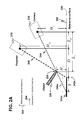
- FIG. 1 provides two examples to illustrate that objects having different heights above a reference surface, under certain conditions, can produce shadows that are substantially-similar in size.
- Example 1 considers a projector-camera arrangement based on a system disclosed in US Patent Application Publication No. 2007/201,863 for detecting if a finger touches a surface.
- Example 1 a projector 110 projects light along a vertical direction onto a reference surface 117 while a camera 115 captures a view of a shadow 130 from a direction shifted from the vertical direction for estimation of an object's height above the reference surface 117 .
- the shadow 130 may be produced by either a first object 120 a or a second object 120 b , both having different heights above the reference surface 117 .
- Example 2 is related to a projector-camera arrangement according to U.S. Pat. No. 6,177,682 for determining a height of an object mounted on a surface.
- an overhead camera 165 captures a view of a shadow 180 produced from light obliquely projected by a projector 160 onto a reference surface 167 .
- the shadow 180 may be produced by different objects 170 a , 170 b , 170 c having different heights above the reference surface 167 .
- the object 107 c touches the reference surface 167 whereas the other objects 107 a , 107 b do not. As a result, it does not lead to a unique solution to the object's height above a reference surface.
- the present invention provides an optical method for obtaining positional or motional information of an object with respect to a reference surface, including detecting if the object touches the reference surface.
- the reference surface may be substantially flat or non-flat.
- the object has a pre-determined reference peripheral point.
- a projector and a camera are used in the disclosed optical method. The projector and the camera are arranged such that when the object not touching the reference surface is illuminated by the projector, a part of the object's shadow formed on the reference surface along a topographical surface line is observable by the camera, the aforesaid part of the shadow having a length being usable for uniquely determining the object's height above the reference surface.
- the topographical surface line is formed by projecting a line-of-sight path joining the camera and the reference peripheral point on the reference surface.
- a surface map is used for mapping a location on the reference surface and a corresponding location in a camera-captured image having a view of the reference surface.
- the method comprises obtaining the surface map and a surface profile of the reference surface for initialization.
- the surface profile provides a height distribution of the reference surface. Detecting if the object is present is then performed until the object is identified to be present. At a time instant after the object is identified to be present, a positional-information obtaining process is initiated.
- This process generates one or more pieces of positional information including whether the object touches the reference surface, the object's height above the reference surface, and a three-dimensional (3D) coordinate of the object.
- this process is repeated at a plurality of time instants, thereby generating a time sequence of 3D coordinates of the object as one piece of motional information.
- the time sequence of the 3D coordinates is usable to generate other pieces of motional information including the object's velocity, its acceleration, a traveling direction, a time history of velocity, a time history of acceleration, and a time history of traveling direction.
- the projector projects a structured-light pattern onto the reference surface.
- the camera then captures an image having a field of view that includes the structured-light pattern on the reference surface.
- the surface map that is configured to map any point on a camera-captured image to a corresponding physical location on the structured-light pattern is computed.
- the surface profile is determined from the structured-light pattern and the corresponding captured image.
- test-for-presence image captured by the camera may be used. The capturing of the test-for-presence image is repeated until the presence of the object is identified.
- the positional-information obtaining process is elaborated as follows. First determine a region-of-interest (ROI) on the reference surface such that the ROI comprises an area surrounding and including the reference peripheral point. After the ROI is determined, spot light is directed to an area that substantially covers at least the ROI such that the object around the reference peripheral point is illuminated on the reference surface. The spot light may be generated from the projector or from a separate light source. The camera then captures a ROI-highlighted image. From the ROI-highlighted image, a camera-observed shadow length and a shadow-projector distance are estimated by using the surface map. If the camera-observed shadow length is found to substantially close to zero, it is determined that the object touches the reference surface, thereby providing a first piece of positional information.
- ROI region-of-interest
- the object's height above the reference surface can be estimated based on a set of data including the surface profile, the camera-observed shadow length, the shadow-projector distance, a distance measured in a reference horizontal direction between the projector and the camera, a distance measured from the projector to the reference surface along a reference vertical direction, and a distance measured from the camera to the reference surface along the reference vertical direction. If the reference surface is substantially flat, the object's height above the reference surface can be computed according to EQN. (4) as stated in the disclosure herein.
- the object's height above the reference surface is a Z coordinate constituting the 3D coordinate of the object.
- a Y coordinate is obtainable based on a distance measured in the reference horizontal direction between the projector and the reference peripheral point. This distance can be computed by either EQN. (3) or EQN. (5) in the disclosure herein.
- An X coordinate can be obtained directly from the camera captured image and the surface map. Preferably, the camera captured image is the ROI-highlighted image. The 3D coordinate obtained thereby provides a third piece of positional information.
- the projector may use infrared light for image projection, or the separate light source is an infrared light source, so that the camera is also configured to sense at least infrared light in image capturing.
- the projector and the camera are arranged such that: in the reference horizontal direction, the projector is positioned between the camera and the object when the object is present; and in the reference vertical direction, the camera is positioned between the projector and the reference surface.
- a mirror is used to reflect any image projected by the projector onto the reference surface, and to reflect any view appeared on the reference surface for the camera to capture.
- FIG. 1 provides two examples to illustrate that different objects having different heights above a reference surface can produce shadows that are substantially-similar in size, so that using the size information of a shadow alone does not lead to a unique solution to the object's height above the reference surface.
- FIG. 2 a depicts a model of an object casting a shadow on a reference surface as used in the development of the present invention, where the model leads to a unique solution of the object's height if a camera-observed shadow length is used in the calculation.
- FIG. 2 b depicts a similar model but a block is put on the reference surface and under the reference peripheral point to emulate an effect that the reference surface is elevated at the location under the object, illustrating that a unique solution of the object's height can also be obtained even if the reference surface is non-flat.
- FIG. 2 c depicts a model similar to the one of FIG. 2 a but a mirror is employed to reflect an image projected by the projector onto the reference surface, and to reflect a view appeared on the reference surface for the camera to capture.
- FIG. 3 provides an overview of steps involved in the determination of positional and motional information in accordance with an exemplary embodiment of the present invention.
- FIG. 4 is a flowchart showing the steps of determining a surface map and a surface profile of the reference surface in accordance with one embodiment of the present invention.
- FIG. 5 is a flowchart showing the steps of detecting a presence of the object in accordance with one embodiment of the present invention.
- FIG. 6 is a flowchart showing the steps of the positional-information obtaining process in accordance with one embodiment of the present invention.
- FIG. 7 depicts an example of a structured-light pattern.
- FIG. 8 depicts an example of a ROI-highlighted image, showing that a camera-observed shadow is produced by an object (which is a finger), whereby a camera-observed shadow length can be obtained to estimate the object's height above the reference surface.
- a reference vertical direction and “a reference horizontal direction” are defined as two directions that are mutually orthogonal, but these two directions are not further defined with reference to the direction of planetary gravity.
- the reference vertical direction is defined herein as a direction substantially perpendicular to the reference surface and the reference horizontal direction is defined with reference to the reference vertical direction.
- the reference surface may be, for example, a floor surface or a surface of a wall.
- an imaginary flat surface sufficiently representative to the reference surface over surface roughness thereon is used instead of the original reference surface in defining the reference vertical direction. That is, the reference vertical direction is defined herein as a direction substantially perpendicular to this imaginary flat surface if the reference surface is not substantially flat.
- a height of an object above a reference surface is defined as a distance measured from a pre-determined reference peripheral point on the object to the reference surface along a reference vertical direction.
- the reference peripheral point is a finger tip where the object is a finger.
- the reference peripheral point is a pencil tip if a pencil is the object.
- Presence of an object means that the object is present in a field of view observable by a camera.
- absence of an object means that the object is absent in the aforementioned field of view.
- FIG. 2 a shows a model of an object casting a shadow on a reference surface.
- the model is used in the development of the present invention.
- a reference vertical direction 202 and a reference horizontal direction 204 are defined with reference to a reference surface 230 .
- An object 220 having a reference peripheral point 225 as pre-determined is illuminated by a projector 210 .
- Light of the projector 210 is blocked by the object 220 so that a shadow 241 a is formed on the reference surface 230 .
- the light of the projector 210 travels along a line-of-sight path 250 and touches the reference peripheral point 225 , thereby forming a starting point 242 a of the shadow 241 a .
- a camera 215 is used to capture a field of view including the object 220 and a part of the shadow 241 a observable by the camera 215 .
- the part of the shadow 241 a observable by the camera 215 is formed along a topographical surface line 235 projected by a line-of-sight path 255 joining the camera 215 and the reference peripheral point 225 .
- the camera-unobservable part of the shadow 241 a is blocked from the camera 215 by the object 220 .
- the part of the shadow 241 a observable by the camera 215 has a camera-observable shadow length 240 a denoted by S.
- H f be a height of the object 220 above the reference surface 230 .
- L f be a distance measured in the reference horizontal direction 204 between the camera 215 and the reference peripheral point 225 .
- D be a shadow-projector distance, defined as a distance measured in the reference horizontal direction 204 between the projector 210 and the starting point 242 a of the shadow 241 a .
- L p be a distance measured in the reference horizontal direction 204 between the projector 210 and the camera 215 .
- H p be a distance measured from the projector 210 to the reference surface 230 along the reference vertical direction 202 .
- H c be a distance measured from the camera 215 to the reference surface 230 along the reference vertical direction 202 .
- H f H c ⁇ H p ⁇ S ( S + D + L p ) ⁇ H p - H c ⁇ D . EQN . ⁇ ( 4 ) It follows that H f , the height of the object 220 above the reference surface 230 , is uniquely determinable based on S (the camera-observable shadow length 240 a ) and D (the shadow-projector distance), both of which can be obtained, as will be explained later, through a camera captured image and a surface map.
- the other parameters involved in EQN. (4), namely, L p , H p and H c may be obtained, e.g., during setting up the camera 215 and the projector 210 .
- L f can be obtained from EQN. (3) with a computed value of H f given by EQN. (4), or can be directly computed by
- L f D + L p - H c ⁇ DS ( S + D + L p ) ⁇ H p - H c ⁇ D . EQN . ⁇ ( 5 )
- a Y coordinate of the object can be obtained as L f .
- an X coordinate of the object is obtainable from a camera captured image and a surface map.
- H f computed from EQN. (4) a three-dimensional (3D) coordinate of the object is obtainable.
- FIG. 2 a depicts that the camera 215 is positioned lower than the projector 210 in the reference vertical direction 202 and located from the object 220 farther than the projector 210 in the reference horizontal direction 204 .
- the present invention is not limited to such positional configuration of the camera 215 and the projector 210 .
- the projector 210 may be lower than the camera 215 in the reference vertical direction 202 , provided that the projector 210 does not block the line-of-sight path 255 .
- the camera 215 may be nearer to the object 220 in the reference horizontal direction 204 than the projector 210 is, provided that the camera 215 does not block the line-of-sight path 250 .
- FIG. 2 b shows a model similar to FIG. 2 a except that a rectangular block 260 of height H o is introduced below the reference peripheral point 225 of the object 220 .
- the introduction of the block 260 is similar to raising the reference surface 230 by a height of H o under the reference peripheral point 225 .
- a distorted shadow 241 b is formed, having a shifted starting point 242 b . It gives rise to a lengthened camera-observed shadow length 240 b , S′, and a shortened shadow-projector distance, D′. It can be shown that
- FIG. 2 c depicts a model that provides a substantially-similar functional effect as of the model of FIG. 2 a .
- a mirror 280 is used to reflect an image projected by a projector 270 onto the reference surface 230 , and to reflect a view appeared on the reference surface 230 for a camera 275 to capture.
- the projector 270 and the camera 275 introduce a virtual projector 271 and a virtual camera 276 , respectively.
- the virtual projector 271 and the virtual camera 276 provide substantially-similar functional effects of the projector 210 and the camera 215 , respectively, of the model of FIG. 2 a.
- the present invention provides an optical method for a system that comprises a projector and a camera to obtain positional or motional information of an object with respect to a reference surface.
- the particular advantage of the present invention is that only one camera is used.
- the object has a pre-determined reference peripheral point.
- the positional information includes whether the object touches the reference surface, the object's height above the reference surface, and a 3D coordinate of the object.
- the motional information includes a time sequence of 3D coordinates.
- the motional information includes the object's velocity, acceleration, traveling direction, and a time history of the same.
- the positional and motional information is with respect to the reference surface in a sense that the 3D coordinate of the object is based on a coordinate system using the reference surface as the XY plane if the reference surface is substantially flat.
- the reference surface is non-flat, an ordinary person in the art is capable of adjusting the coordinate system with a knowledge of a surface profile of the reference surface.
- FIG. 3 is a flowchart providing an overview of major steps involved in the method in accordance with an exemplary embodiment of the present invention.
- a first step 310 of the method is to obtain a surface profile of the reference surface, and a surface map.
- the surface profile characterizes a height distribution over the reference surface.
- the surface map is configured to map any point (or any pixel) on an image captured by the camera to a corresponding physical location on the reference surface. By using the surface map, a point or a pixel of interest identified on the captured image can be mapped to the corresponding location on the reference surface.
- the step 310 is performed at initial system start-up.
- the system detects if the object is present until the object is identified to be present.
- the identification of the object's presence triggers performing a subsequent step 330 .
- a positional-information obtaining process is initiated at a time instant after the object is identified to be present, where this process generates one or more pieces of positional information.
- the motional information can be computed in a step 340 .
- the positional-information obtaining process in the step 330 and the computation of motional information in the step 340 are repeated a number of times by performing the steps 330 , 340 at a plurality of time instants.
- the time instants are selected under certain hardware constraints such as the need to align with frame rates of the projector and of the camera.
- the disclosed method is characterized by arranging the projector and the camera with a positional configuration such that when the object not touching the reference surface is illuminated by the projector, a part of the object's shadow on the reference surface is observable by the camera.
- the shadow is formed along a topographical surface line projected by a line-of-sight path joining the camera and the reference peripheral point.
- a length of the aforesaid part of the shadow is usable for uniquely determining the object's height above the reference surface in the positional-information obtaining process. This length is regarded as a camera-observed shadow length.
- the surface map and the surface profile can be determined by techniques disclosed in U.S. patent application Ser. No. 13/474,567.
- FIG. 4 illustrates determination of a surface map and a surface profile of the reference surface based on one of the aforementioned techniques and in accordance with one embodiment of the present invention.
- the projector first projects a structured-light pattern onto the reference surface (step 410 ).
- the structured-light pattern is usually designed as a regular pattern such as a structured grid, a regular grid or a rectangular grid.
- FIG. 7 shows one rectangular grid. Consider using a rectangular grid 710 as an example for realizing the structured-light pattern.
- the rectangular grid 710 has a plurality of crossing points 721 - 728 .
- crossing points 721 - 728 can be easily recognized in a camera-captured image having a view that includes the reference surface projected with the rectangular grid 710 .
- Each of these crossing points 721 - 728 as recognized in the camera-captured image has a one-to-one correspondence with a corresponding point of the structured-light pattern. Knowing the projector's height above the reference surface and the projection angle of the projector, one can obtain a physical location (i.e. an XY coordinate) of each of the crossing points 721 - 728 of the structured-light pattern projected on the reference surface.
- the surface map can therefore be estimated and constructed. For a non-flat reference surface, lines of the rectangular grid 710 are distorted and/or interrupted when projected on this reference surface.
- the surface profile can be estimated.
- the determination of the surface map and the surface profile is summarized as follows.
- the camera captures an image of the structured-light pattern that is projected on the reference surface (step 420 ).
- the surface map is then computed based on matching a set of points on the structured-light pattern and an identifiable set of corresponding points in the captured image (step 430 ).
- the surface profile can also be determined from the structured-light pattern and the captured image (step 440 ).
- whether or not the object is present is determined according to a test-for-presence image captured by the camera when a second structured-light pattern is projected by the projector onto the reference surface.
- FIG. 5 is a flowchart illustrating the detection of the object's presence in accordance with this embodiment.
- the projector projects the second structured-light pattern onto the reference surface (step 510 ).
- the second structured-light pattern is either the structured-light pattern used in the determination of the surface map and the surface profile, or another structured-light pattern adapted to or optimized for the reference surface after the surface profile is obtained. Using said another structured-light pattern is preferable for a non-flat reference surface.
- the camera then captures a test-for-presence image (step 520 ).
- the test-for-presence image is compared with a control image of the second structured-light pattern (step 530 ).
- This control image can be obtained by the camera capturing a view of the second structured-light pattern on the reference surface in the absence of the object.
- the control image can also be obtained by computing from the second structured-light pattern according to the surface map.
- One approach for comparing the test-for-presence image and the control image is by computing a difference image between the test-for-presence image and the control image.
- the test-for-presence image and the control image are substantially similar so that a majority part of the difference image contains pixels having values close to zero or below a certain threshold value.
- the presence of the object is determinable by, for example, identifying a contiguous region in the difference image where a substantial part of the contiguous region has pixel values greater than the threshold value. Detecting the possible presence of the object by using the difference image has an advantage that computation of the difference image is fast due to computational parallelism so that the frequency of performing detection can be made high.
- the second structured-light pattern is compared with a reconstructed light pattern obtained from the test-for-presence image (step 535 ).
- the reconstructed light pattern is reconstructed from the test-for-presence image according to the surface map such that the reconstructed light pattern, if under an assumption of the object's absence, should substantially be similar with the second structured-light pattern. Similar to the first object-detecting option disclosed above, a difference image between the second structured-light pattern and the reconstructed light pattern may be computed for detecting if the object is present. The steps 520 and 530 (or 535 ) are repeated until the object's presence is identified (decision-making step 540 ).
- FIG. 6 is a flowchart illustrating the positional-information obtaining process in accordance with one embodiment of the present invention.
- a region-of-interest (ROI) on the reference surface is determined.
- the ROI comprises an area surrounding and including the reference peripheral point.
- the determination of the ROI in the step 610 is accomplished based on the last test-for-presence image obtained in the step 320 .
- the ROI is identified by recognizing a pattern on said last test-for-presence image such that the pattern substantially matches the object's feature around the reference peripheral point.
- the determination of the ROI for a current time instant is simplified with a knowledge of the previously determined ROI in that performing a verification whether the reference peripheral point still resides in the previously determined ROI or a prediction of current ROI position based on the previous reference peripheral point moving trajectory is easier than doing a pattern recognition over a large area.
- spot light is directed to an area that substantially covers at least the ROI such that the object around the reference peripheral point is illuminated to form a shadow on the reference surface unless the object is substantially close to the reference surface (step 620 ).
- the spot light is generated by the projector.
- the spot light may also be generated from a separate light source other than the projector.
- the part of the shadow observable by the camera is formed along a topographical surface line projected by joining the camera and the reference peripheral point.
- the camera is then used to capture a ROI-highlighted image (step 625 ).
- An example of the ROI-highlighted image is depicted in FIG. 8 .
- the object is a finger 830 and the reference peripheral point is a finger tip 835 of the finger 830 .
- the spot light 820 is projected onto a reference surface 810 , forming a shadow 840 .
- a camera-observed shadow length is estimated (step 630 ).
- the camera-observed shadow length is a length of the part of the shadow observable by the camera. Estimation of the camera-observed shadow length from the ROI-highlighted image is accomplished by using the surface map.
- the camera-observed shadow length is substantially close to zero, it can be determined that the object touches the reference surface (step 640 ). It thereby provides a first piece of positional information. Practically, the camera-observed shadow length is considered to be substantially close to zero if this length is less than a certain threshold value, or if the part of the object's shadow that can be observed by the camera is not detectable. In certain practical applications, it may be sufficient to confirm that the object touches the reference surface. In one embodiment, the positional-information obtaining process is stopped and a next process is initiated if it is confirmed that the object touches the reference surface.
- the shadow-projector distance is estimated from the ROI-highlighted image by using the surface map (step 650 ).
- the shadow-projector distance is the distance measured in the reference horizontal direction between the projector and the starting point of the shadow where the starting point is the particular point on the shadow cast by the reference peripheral point.
- a second piece of positional information provided by the disclosed method is the object's height above the reference surface.
- the object's height above the reference surface (H f ) is estimated in a step 660 based on a set of data including the surface profile, the camera-observed shadow length (S), the shadow-projector distance (D), a distance measured in the reference horizontal direction between the projector and the camera (L p ), a distance measured from the projector to the reference surface along a reference vertical direction (H p ), and a distance measured from the camera to the reference surface along the reference vertical direction (H c ).
- the object's height above the reference surface can be computed according to EQN. (4). Note that if the camera-observed shadow length is found to be substantially close to zero, the object's height above the reference surface may be directly set to zero. Also note that the object's height above the reference surface is a Z coordinate constituting the 3D coordinate of the object.
- an XY coordinate of the object is obtainable as follows.
- the Y coordinate can be taken as the distance in the reference horizontal direction between the camera and the reference peripheral point (i.e. L f ).
- the distance L f is computed by either EQN. (3) or EQN. (5) (step 670 ).
- the X coordinate of the object can be obtained directly from a camera captured image and the surface map by identifying the object's position in this camera captured image and then mapping this position to the physical position of the object based on the surface map (step 675 ).
- this camera captured image is the ROI-highlighted image obtained in the step 625 .
- the 3D coordinate of the object is then obtained based on the XY coordinate, and the object's height above the reference surface as the Z coordinate (step 680 ), thereby providing a third piece of positional information.
- the positional-information obtaining process is repeated for a number of times so as to obtain a time sequence of 3D coordinates of the object.
- This time sequence thereby provides a first piece of motional information.
- one or more pieces of motional information of the object are obtained. Examples of such one or more pieces of motional information include the object's velocity, an acceleration of the object, a traveling direction thereof, a time history of velocity, a time history of acceleration, and a time history of traveling direction.
- the projector may use visible or invisible light for image projection.
- the choice of light depends on applications. For example, an interactive projection system requiring an input from a user by pressing his or her finger on a touch pad is preferred to use invisible light, preferably infrared light, for the projector.
- invisible light preferably infrared light
- infrared light may also be used by the separate light source in generating the spot light.
- the camera is then configured to sense at least infrared light in image capturing.
- the projector and the camera are arranged such that (i) a shadow of an object is produced on a reference surface, and (ii) the camera has a field of view preferably covering the whole structured-light pattern projected on the reference surface.
- the projector and the camera are arranged with a positional configuration that (i) in the reference horizontal direction, the projector is positioned between the camera and the object when the object is present, and (ii) in the reference vertical direction, the camera is positioned between the projector and the reference surface. It is also optional that a mirror is used to reflect any image projected by the projector onto the reference surface, and to reflect any view appeared on the reference surface for the camera to capture.
- the structured-light pattern and the second structured-light pattern that is selected are the same. If the spot light is generated by the separate light source, the projector may be required to project the structured-light pattern only. Under such condition, one low-cost realization of the projector is a light source configured to give out a fixed light pattern.
- a system for obtaining positional or motional information of an object with respect to a reference surface is realizable by including a projector and a camera in the system, and configuring the system itself to determine the aforesaid positional or motional information by an embodiment of the disclosed method according to the foregoing description.
- the system is realized as a single unit integrated with the projector and the camera.
- one or more processors are embedded in the system for performing computation and estimation steps of the disclosed method.
- the method and the system disclosed herein may be used in or as an interactive projection system.
- the object is a finger of a user
- the reference peripheral point is a finger tip of the finger. A presence of the finger touching the reference surface as detected provides user-input information to the interactive projection system.
Abstract
Description
Furthermore, similarity between the two triangles having edges overlapped with the line-of-
From EQN. (1), expressing Lf in terms of Hf gives
Substituting EQN. (3) into EQN. (2) followed by algebraic manipulation yields
It follows that Hf, the height of the
A Y coordinate of the object can be obtained as Lf. As will be shown later, an X coordinate of the object is obtainable from a camera captured image and a surface map. With a further knowledge of Hf computed from EQN. (4), a three-dimensional (3D) coordinate of the object is obtainable.
Therefore, Hf is still uniquely determinable. This result implies that even if the
Claims (21)
Priority Applications (3)
| Application Number | Priority Date | Filing Date | Title |
|---|---|---|---|
| US14/102,506 US9429417B2 (en) | 2012-05-17 | 2013-12-11 | Touch and motion detection using surface map, object shadow and a single camera |
| CN201410009366.5A CN103824282B (en) | 2013-12-11 | 2014-01-09 | Touch and motion detection using surface mapping figure, shadow of object and camera |
| US15/207,502 US9857919B2 (en) | 2012-05-17 | 2016-07-12 | Wearable device with intelligent user-input interface |
Applications Claiming Priority (2)
| Application Number | Priority Date | Filing Date | Title |
|---|---|---|---|
| US13/474,567 US9092090B2 (en) | 2012-05-17 | 2012-05-17 | Structured light for touch or gesture detection |
| US14/102,506 US9429417B2 (en) | 2012-05-17 | 2013-12-11 | Touch and motion detection using surface map, object shadow and a single camera |
Related Parent Applications (1)
| Application Number | Title | Priority Date | Filing Date |
|---|---|---|---|
| US13/474,567 Continuation-In-Part US9092090B2 (en) | 2012-05-17 | 2012-05-17 | Structured light for touch or gesture detection |
Related Child Applications (1)
| Application Number | Title | Priority Date | Filing Date |
|---|---|---|---|
| US15/207,502 Continuation-In-Part US9857919B2 (en) | 2012-05-17 | 2016-07-12 | Wearable device with intelligent user-input interface |
Publications (2)
| Publication Number | Publication Date |
|---|---|
| US20140098224A1 US20140098224A1 (en) | 2014-04-10 |
| US9429417B2 true US9429417B2 (en) | 2016-08-30 |
Family
ID=50432390
Family Applications (1)
| Application Number | Title | Priority Date | Filing Date |
|---|---|---|---|
| US14/102,506 Active 2033-04-26 US9429417B2 (en) | 2012-05-17 | 2013-12-11 | Touch and motion detection using surface map, object shadow and a single camera |
Country Status (1)
| Country | Link |
|---|---|
| US (1) | US9429417B2 (en) |
Families Citing this family (18)
| Publication number | Priority date | Publication date | Assignee | Title |
|---|---|---|---|---|
| US9857919B2 (en) | 2012-05-17 | 2018-01-02 | Hong Kong Applied Science And Technology Research | Wearable device with intelligent user-input interface |
| US9904414B2 (en) * | 2012-12-10 | 2018-02-27 | Seiko Epson Corporation | Display device, and method of controlling display device |
| US9304599B2 (en) | 2014-03-21 | 2016-04-05 | Dell Products L.P. | Gesture controlled adaptive projected information handling system input and output devices |
| US10133355B2 (en) | 2014-03-21 | 2018-11-20 | Dell Products L.P. | Interactive projected information handling system support input and output devices |
| US9965038B2 (en) | 2014-03-21 | 2018-05-08 | Dell Products L.P. | Context adaptable projected information handling system input environment |
| US20150268773A1 (en) * | 2014-03-21 | 2015-09-24 | Dell Products L.P. | Projected Information Handling System Input Interface with Dynamic Adjustment |
| US10664090B2 (en) | 2014-07-31 | 2020-05-26 | Hewlett-Packard Development Company, L.P. | Touch region projection onto touch-sensitive surface |
| WO2016053269A1 (en) | 2014-09-30 | 2016-04-07 | Hewlett-Packard Development Company, L. P. | Displaying an object indicator |
| US10785428B2 (en) | 2015-10-16 | 2020-09-22 | Capsovision Inc. | Single image sensor for capturing mixed structured-light images and regular images |
| US9936151B2 (en) | 2015-10-16 | 2018-04-03 | Capsovision Inc | Single image sensor for capturing mixed structured-light images and regular images |
| US10402992B2 (en) | 2015-10-16 | 2019-09-03 | Capsovision Inc. | Method and apparatus for endoscope with distance measuring for object scaling |
| WO2017149875A1 (en) * | 2016-02-29 | 2017-09-08 | ソニー株式会社 | Image capture control device, image capture device, and image capture control method |
| CN105825524B (en) * | 2016-03-10 | 2018-07-24 | 浙江生辉照明有限公司 | Method for tracking target and device |
| JP2018006818A (en) * | 2016-06-27 | 2018-01-11 | キヤノン株式会社 | Image reading method and image reading device |
| WO2018010207A1 (en) * | 2016-07-12 | 2018-01-18 | Hong Kong Applied Science & Technology Research Institute Company Limited | Wearable Device with Intelligent User-Input Interface |
| CN106415460B (en) * | 2016-07-12 | 2019-04-09 | 香港应用科技研究院有限公司 | Wearable device with intelligent subscriber input interface |
| US10638104B2 (en) * | 2018-09-14 | 2020-04-28 | Christie Digital Systems Usa, Inc. | Device, system and method for generating updated camera-projector correspondences from a reduced set of test patterns |
| US20210409617A1 (en) * | 2020-06-24 | 2021-12-30 | Micron Technology, Inc. | Displaying a three-dimensional image of a user using an array of infrared illuminators |
Citations (22)
| Publication number | Priority date | Publication date | Assignee | Title |
|---|---|---|---|---|
| US6177682B1 (en) | 1998-10-21 | 2001-01-23 | Novacam Tyechnologies Inc. | Inspection of ball grid arrays (BGA) by using shadow images of the solder balls |
| US20040032974A1 (en) * | 2002-08-14 | 2004-02-19 | Kriesel Marshall S. | Methods and apparatus for the dimensional measurement of livestock using a single camera |
| CN1477478A (en) | 2002-08-20 | 2004-02-25 | 昆盈企业股份有限公司 | Finger-moving type pointer input-method and its device |
| US20040227992A1 (en) * | 1999-12-08 | 2004-11-18 | Neurok Llc | Three-dimensional free space image projection employing Fresnel lenses |
| US20050036672A1 (en) * | 2003-08-11 | 2005-02-17 | Palo Alto Research Center, Incorporated | Three-dimensional active vision with glyph address carpet |
| US20050174581A1 (en) * | 2002-02-09 | 2005-08-11 | Lang Liu | Sensing device for measuring the three-dimension shape and its measuring method |
| US6965460B1 (en) * | 2000-08-08 | 2005-11-15 | Hewlett-Packard Development Company, L.P. | Method and system for scanning an image using a look-down linear array scanner |
| US20050271264A1 (en) * | 2004-04-21 | 2005-12-08 | Topcon Corporation | Three-dimensional image measuring apparatus and method |
| US20060001739A1 (en) * | 2004-06-17 | 2006-01-05 | Noam Babayoff | Method and apparatus for colour imaging a three-dimensional structure |
| US20060038879A1 (en) * | 2003-12-21 | 2006-02-23 | Kremen Stanley H | System and apparatus for recording, transmitting, and projecting digital three-dimensional images |
| US20060158662A1 (en) * | 2005-01-17 | 2006-07-20 | Fraunhofer-Gesellschaft Zur Foerderung Der Angewandten Forschung E.V. | Scanner and method for operating a scanner |
| US20070201863A1 (en) | 2006-02-28 | 2007-08-30 | Microsoft Corporation | Compact interactive tabletop with projection-vision |
| US20080214233A1 (en) * | 2007-03-01 | 2008-09-04 | Microsoft Corporation | Connecting mobile devices via interactive input medium |
| US20080231926A1 (en) * | 2007-03-19 | 2008-09-25 | Klug Michael A | Systems and Methods for Updating Dynamic Three-Dimensional Displays with User Input |
| US20100134428A1 (en) * | 2007-07-11 | 2010-06-03 | Oh Eui Jin | Data input device by detecting finger's moving and the input process thereof |
| US20100255179A1 (en) * | 2009-04-06 | 2010-10-07 | Terepac | Systems and methods for printing electronic device assembly |
| US8042947B1 (en) * | 2000-10-07 | 2011-10-25 | Metaio Gmbh | Information system |
| US20120243747A1 (en) * | 2011-03-01 | 2012-09-27 | Kielkopf John F | System and Method for Precision Measurement of Position, Motion and Resonances |
| US20120293630A1 (en) * | 2011-05-19 | 2012-11-22 | Qualcomm Incorporated | Method and apparatus for multi-camera motion capture enhancement using proximity sensors |
| US20130153651A1 (en) * | 2011-12-20 | 2013-06-20 | Elena A. Fedorovskaya | Encoding information in illumination patterns |
| US20130156330A1 (en) * | 2011-12-20 | 2013-06-20 | Paul J. Kane | Encoding information in illumination patterns |
| US9092090B2 (en) * | 2012-05-17 | 2015-07-28 | Hong Kong Applied Science And Technology Research Institute Co., Ltd. | Structured light for touch or gesture detection |
-
2013
- 2013-12-11 US US14/102,506 patent/US9429417B2/en active Active
Patent Citations (24)
| Publication number | Priority date | Publication date | Assignee | Title |
|---|---|---|---|---|
| US6177682B1 (en) | 1998-10-21 | 2001-01-23 | Novacam Tyechnologies Inc. | Inspection of ball grid arrays (BGA) by using shadow images of the solder balls |
| US20040227992A1 (en) * | 1999-12-08 | 2004-11-18 | Neurok Llc | Three-dimensional free space image projection employing Fresnel lenses |
| US6965460B1 (en) * | 2000-08-08 | 2005-11-15 | Hewlett-Packard Development Company, L.P. | Method and system for scanning an image using a look-down linear array scanner |
| US8042947B1 (en) * | 2000-10-07 | 2011-10-25 | Metaio Gmbh | Information system |
| US20050174581A1 (en) * | 2002-02-09 | 2005-08-11 | Lang Liu | Sensing device for measuring the three-dimension shape and its measuring method |
| US20040032974A1 (en) * | 2002-08-14 | 2004-02-19 | Kriesel Marshall S. | Methods and apparatus for the dimensional measurement of livestock using a single camera |
| CN1477478A (en) | 2002-08-20 | 2004-02-25 | 昆盈企业股份有限公司 | Finger-moving type pointer input-method and its device |
| US20050036672A1 (en) * | 2003-08-11 | 2005-02-17 | Palo Alto Research Center, Incorporated | Three-dimensional active vision with glyph address carpet |
| US20060038879A1 (en) * | 2003-12-21 | 2006-02-23 | Kremen Stanley H | System and apparatus for recording, transmitting, and projecting digital three-dimensional images |
| US20050271264A1 (en) * | 2004-04-21 | 2005-12-08 | Topcon Corporation | Three-dimensional image measuring apparatus and method |
| US20100208275A1 (en) * | 2004-06-17 | 2010-08-19 | Cadent Ltd. | Method and apparatus for colour imaging a three-dimensional structure |
| US20060001739A1 (en) * | 2004-06-17 | 2006-01-05 | Noam Babayoff | Method and apparatus for colour imaging a three-dimensional structure |
| US20080024768A1 (en) * | 2004-06-17 | 2008-01-31 | Cadent Ltd | Method and apparatus for colour imaging a three-dimensional structure |
| US20060158662A1 (en) * | 2005-01-17 | 2006-07-20 | Fraunhofer-Gesellschaft Zur Foerderung Der Angewandten Forschung E.V. | Scanner and method for operating a scanner |
| US20070201863A1 (en) | 2006-02-28 | 2007-08-30 | Microsoft Corporation | Compact interactive tabletop with projection-vision |
| US20080214233A1 (en) * | 2007-03-01 | 2008-09-04 | Microsoft Corporation | Connecting mobile devices via interactive input medium |
| US20080231926A1 (en) * | 2007-03-19 | 2008-09-25 | Klug Michael A | Systems and Methods for Updating Dynamic Three-Dimensional Displays with User Input |
| US20100134428A1 (en) * | 2007-07-11 | 2010-06-03 | Oh Eui Jin | Data input device by detecting finger's moving and the input process thereof |
| US20100255179A1 (en) * | 2009-04-06 | 2010-10-07 | Terepac | Systems and methods for printing electronic device assembly |
| US20120243747A1 (en) * | 2011-03-01 | 2012-09-27 | Kielkopf John F | System and Method for Precision Measurement of Position, Motion and Resonances |
| US20120293630A1 (en) * | 2011-05-19 | 2012-11-22 | Qualcomm Incorporated | Method and apparatus for multi-camera motion capture enhancement using proximity sensors |
| US20130153651A1 (en) * | 2011-12-20 | 2013-06-20 | Elena A. Fedorovskaya | Encoding information in illumination patterns |
| US20130156330A1 (en) * | 2011-12-20 | 2013-06-20 | Paul J. Kane | Encoding information in illumination patterns |
| US9092090B2 (en) * | 2012-05-17 | 2015-07-28 | Hong Kong Applied Science And Technology Research Institute Co., Ltd. | Structured light for touch or gesture detection |
Non-Patent Citations (2)
| Title |
|---|
| P. Song et al., "Vision-based projected tabletop interface for finger interactions," Proceedings of 2007 IEEE International Conference on Human-Computer Interaction (HCI 2007), pp. 49-58, Dec. 31, 2007. |
| Search report issued from SIPO on Feb. 24, 2016, for a related China application. |
Also Published As
| Publication number | Publication date |
|---|---|
| US20140098224A1 (en) | 2014-04-10 |
Similar Documents
| Publication | Publication Date | Title |
|---|---|---|
| US9429417B2 (en) | Touch and motion detection using surface map, object shadow and a single camera | |
| US9600078B2 (en) | Method and system enabling natural user interface gestures with an electronic system | |
| JP5865910B2 (en) | Depth camera based on structured light and stereoscopic vision | |
| JP6480434B2 (en) | System and method for direct pointing detection for interaction with digital devices | |
| US9001208B2 (en) | Imaging sensor based multi-dimensional remote controller with multiple input mode | |
| US8401225B2 (en) | Moving object segmentation using depth images | |
| US9465444B1 (en) | Object recognition for gesture tracking | |
| KR102110811B1 (en) | System and method for human computer interaction | |
| TW201814438A (en) | Virtual reality scene-based input method and device | |
| CN103824282B (en) | Touch and motion detection using surface mapping figure, shadow of object and camera | |
| US20140292648A1 (en) | Information operation display system, display program, and display method | |
| TWI431538B (en) | Image based motion gesture recognition method and system thereof | |
| KR101330531B1 (en) | Method of virtual touch using 3D camera and apparatus thereof | |
| KR20170081808A (en) | System and method for detecting object in depth image | |
| US20240111382A1 (en) | Touch recognition method and device having lidar sensor | |
| US10606372B2 (en) | System and method for interaction with a computer implemented interactive application using a depth aware camera | |
| TWI521387B (en) | A re-anchorable virtual panel in 3d space | |
| JP6070211B2 (en) | Information processing apparatus, system, image projection apparatus, information processing method, and program | |
| US9857919B2 (en) | Wearable device with intelligent user-input interface | |
| KR101575063B1 (en) | multi-user recognition multi-touch interface apparatus and method using depth-camera | |
| TWI424343B (en) | Optical screen touch system and method thereof | |
| KR20090116544A (en) | Apparatus and method for space touch sensing and screen apparatus sensing infrared camera | |
| JP2018169720A (en) | Motion detection system | |
| Alex et al. | LampTop: Touch detection for a projector-camera system based on shape classification | |
| Niikura et al. | Touch detection system for various surfaces using shadow of finger |
Legal Events
| Date | Code | Title | Description |
|---|---|---|---|
| AS | Assignment |
Owner name: HONG KONG APPLIED SCIENCE AND TECHNOLOGY RESEARCH Free format text: ASSIGNMENT OF ASSIGNORS INTEREST;ASSIGNOR:ZHANG, WEI;REEL/FRAME:031755/0290 Effective date: 20131120 |
|
| STCF | Information on status: patent grant |
Free format text: PATENTED CASE |
|
| MAFP | Maintenance fee payment |
Free format text: PAYMENT OF MAINTENANCE FEE, 4TH YEAR, LARGE ENTITY (ORIGINAL EVENT CODE: M1551); ENTITY STATUS OF PATENT OWNER: LARGE ENTITY Year of fee payment: 4 |
|
| MAFP | Maintenance fee payment |
Free format text: PAYMENT OF MAINTENANCE FEE, 8TH YEAR, LARGE ENTITY (ORIGINAL EVENT CODE: M1552); ENTITY STATUS OF PATENT OWNER: LARGE ENTITY Year of fee payment: 8 |