US9387086B2 - Intervertebral implant with keel - Google Patents
Intervertebral implant with keel Download PDFInfo
- Publication number
- US9387086B2 US9387086B2 US14/643,287 US201514643287A US9387086B2 US 9387086 B2 US9387086 B2 US 9387086B2 US 201514643287 A US201514643287 A US 201514643287A US 9387086 B2 US9387086 B2 US 9387086B2
- Authority
- US
- United States
- Prior art keywords
- saw blade
- keel
- slot
- instrument system
- disposed
- Prior art date
- Legal status (The legal status is an assumption and is not a legal conclusion. Google has not performed a legal analysis and makes no representation as to the accuracy of the status listed.)
- Active
Links
- 239000007943 implant Substances 0.000 title claims abstract description 89
- 238000003780 insertion Methods 0.000 claims description 15
- 230000037431 insertion Effects 0.000 claims description 15
- 230000036346 tooth eruption Effects 0.000 claims description 8
- 230000033001 locomotion Effects 0.000 claims description 5
- 239000000463 material Substances 0.000 abstract description 28
- 230000008468 bone growth Effects 0.000 abstract description 6
- 230000008901 benefit Effects 0.000 abstract description 4
- 238000010276 construction Methods 0.000 abstract description 2
- 210000000988 bone and bone Anatomy 0.000 description 23
- 238000013461 design Methods 0.000 description 8
- 238000000034 method Methods 0.000 description 8
- 230000002829 reductive effect Effects 0.000 description 8
- 230000004927 fusion Effects 0.000 description 7
- 230000013011 mating Effects 0.000 description 7
- 229910003460 diamond Inorganic materials 0.000 description 5
- 239000010432 diamond Substances 0.000 description 5
- 229910052751 metal Inorganic materials 0.000 description 5
- 239000002184 metal Substances 0.000 description 5
- 238000003801 milling Methods 0.000 description 5
- OKTJSMMVPCPJKN-UHFFFAOYSA-N Carbon Chemical compound [C] OKTJSMMVPCPJKN-UHFFFAOYSA-N 0.000 description 4
- 210000003484 anatomy Anatomy 0.000 description 4
- 229910052799 carbon Inorganic materials 0.000 description 4
- 239000000919 ceramic Substances 0.000 description 4
- 238000000576 coating method Methods 0.000 description 4
- 238000005553 drilling Methods 0.000 description 4
- 230000009467 reduction Effects 0.000 description 4
- RTAQQCXQSZGOHL-UHFFFAOYSA-N Titanium Chemical compound [Ti] RTAQQCXQSZGOHL-UHFFFAOYSA-N 0.000 description 3
- 239000011248 coating agent Substances 0.000 description 3
- 238000003384 imaging method Methods 0.000 description 3
- 239000004033 plastic Substances 0.000 description 3
- 229920003023 plastic Polymers 0.000 description 3
- 238000004381 surface treatment Methods 0.000 description 3
- 239000010936 titanium Substances 0.000 description 3
- 229910052719 titanium Inorganic materials 0.000 description 3
- 229910001069 Ti alloy Inorganic materials 0.000 description 2
- 230000009471 action Effects 0.000 description 2
- 239000000853 adhesive Substances 0.000 description 2
- 230000001070 adhesive effect Effects 0.000 description 2
- 230000002022 anti-cellular effect Effects 0.000 description 2
- 238000011882 arthroplasty Methods 0.000 description 2
- 239000003795 chemical substances by application Substances 0.000 description 2
- 230000003247 decreasing effect Effects 0.000 description 2
- 230000001788 irregular Effects 0.000 description 2
- 230000000399 orthopedic effect Effects 0.000 description 2
- 238000002360 preparation method Methods 0.000 description 2
- 230000000979 retarding effect Effects 0.000 description 2
- 238000001356 surgical procedure Methods 0.000 description 2
- 210000001519 tissue Anatomy 0.000 description 2
- 229910000684 Cobalt-chrome Inorganic materials 0.000 description 1
- 206010061246 Intervertebral disc degeneration Diseases 0.000 description 1
- 239000004696 Poly ether ether ketone Substances 0.000 description 1
- NRTOMJZYCJJWKI-UHFFFAOYSA-N Titanium nitride Chemical compound [Ti]#N NRTOMJZYCJJWKI-UHFFFAOYSA-N 0.000 description 1
- 230000001133 acceleration Effects 0.000 description 1
- 229910045601 alloy Inorganic materials 0.000 description 1
- 239000000956 alloy Substances 0.000 description 1
- 229940121363 anti-inflammatory agent Drugs 0.000 description 1
- 239000002260 anti-inflammatory agent Substances 0.000 description 1
- 239000003146 anticoagulant agent Substances 0.000 description 1
- 229940127219 anticoagulant drug Drugs 0.000 description 1
- 230000009286 beneficial effect Effects 0.000 description 1
- JUPQTSLXMOCDHR-UHFFFAOYSA-N benzene-1,4-diol;bis(4-fluorophenyl)methanone Chemical compound OC1=CC=C(O)C=C1.C1=CC(F)=CC=C1C(=O)C1=CC=C(F)C=C1 JUPQTSLXMOCDHR-UHFFFAOYSA-N 0.000 description 1
- 239000012620 biological material Substances 0.000 description 1
- 239000008280 blood Substances 0.000 description 1
- 230000036770 blood supply Effects 0.000 description 1
- 239000002639 bone cement Substances 0.000 description 1
- 230000010261 cell growth Effects 0.000 description 1
- 239000004568 cement Substances 0.000 description 1
- 230000001112 coagulating effect Effects 0.000 description 1
- 239000010952 cobalt-chrome Substances 0.000 description 1
- 239000002131 composite material Substances 0.000 description 1
- 238000013270 controlled release Methods 0.000 description 1
- 238000013016 damping Methods 0.000 description 1
- 208000018180 degenerative disc disease Diseases 0.000 description 1
- 238000011161 development Methods 0.000 description 1
- 230000018109 developmental process Effects 0.000 description 1
- 230000009977 dual effect Effects 0.000 description 1
- 230000000694 effects Effects 0.000 description 1
- 239000002783 friction material Substances 0.000 description 1
- 230000012010 growth Effects 0.000 description 1
- 230000035876 healing Effects 0.000 description 1
- 230000011132 hemopoiesis Effects 0.000 description 1
- 238000002513 implantation Methods 0.000 description 1
- 230000002401 inhibitory effect Effects 0.000 description 1
- 208000021600 intervertebral disc degenerative disease Diseases 0.000 description 1
- 230000007794 irritation Effects 0.000 description 1
- 230000000670 limiting effect Effects 0.000 description 1
- 230000014759 maintenance of location Effects 0.000 description 1
- 150000002739 metals Chemical class 0.000 description 1
- 238000012986 modification Methods 0.000 description 1
- 230000004048 modification Effects 0.000 description 1
- 210000005036 nerve Anatomy 0.000 description 1
- 230000000414 obstructive effect Effects 0.000 description 1
- 230000011164 ossification Effects 0.000 description 1
- 210000004197 pelvis Anatomy 0.000 description 1
- 229920001652 poly(etherketoneketone) Polymers 0.000 description 1
- 229920002530 polyetherether ketone Polymers 0.000 description 1
- 229920000642 polymer Polymers 0.000 description 1
- 239000002861 polymer material Substances 0.000 description 1
- 238000003825 pressing Methods 0.000 description 1
- 230000002265 prevention Effects 0.000 description 1
- 230000000717 retained effect Effects 0.000 description 1
- 210000004872 soft tissue Anatomy 0.000 description 1
- 238000005476 soldering Methods 0.000 description 1
- 239000007787 solid Substances 0.000 description 1
- 239000010935 stainless steel Substances 0.000 description 1
- 229910001220 stainless steel Inorganic materials 0.000 description 1
- 230000003313 weakening effect Effects 0.000 description 1
- 210000000707 wrist Anatomy 0.000 description 1
Images


Classifications
-
- A—HUMAN NECESSITIES
- A61—MEDICAL OR VETERINARY SCIENCE; HYGIENE
- A61F—FILTERS IMPLANTABLE INTO BLOOD VESSELS; PROSTHESES; DEVICES PROVIDING PATENCY TO, OR PREVENTING COLLAPSING OF, TUBULAR STRUCTURES OF THE BODY, e.g. STENTS; ORTHOPAEDIC, NURSING OR CONTRACEPTIVE DEVICES; FOMENTATION; TREATMENT OR PROTECTION OF EYES OR EARS; BANDAGES, DRESSINGS OR ABSORBENT PADS; FIRST-AID KITS
- A61F2/00—Filters implantable into blood vessels; Prostheses, i.e. artificial substitutes or replacements for parts of the body; Appliances for connecting them with the body; Devices providing patency to, or preventing collapsing of, tubular structures of the body, e.g. stents
- A61F2/02—Prostheses implantable into the body
- A61F2/30—Joints
- A61F2/44—Joints for the spine, e.g. vertebrae, spinal discs
- A61F2/442—Intervertebral or spinal discs, e.g. resilient
-
- A—HUMAN NECESSITIES
- A61—MEDICAL OR VETERINARY SCIENCE; HYGIENE
- A61B—DIAGNOSIS; SURGERY; IDENTIFICATION
- A61B17/00—Surgical instruments, devices or methods, e.g. tourniquets
- A61B17/14—Surgical saws ; Accessories therefor
-
- A—HUMAN NECESSITIES
- A61—MEDICAL OR VETERINARY SCIENCE; HYGIENE
- A61B—DIAGNOSIS; SURGERY; IDENTIFICATION
- A61B17/00—Surgical instruments, devices or methods, e.g. tourniquets
- A61B17/14—Surgical saws ; Accessories therefor
- A61B17/142—Surgical saws ; Accessories therefor with reciprocating saw blades, e.g. with cutting edges at the distal end of the saw blades
- A61B17/144—Surgical saws ; Accessories therefor with reciprocating saw blades, e.g. with cutting edges at the distal end of the saw blades with cutting edges at the side of the saw blades
-
- A61B17/148—
-
- A—HUMAN NECESSITIES
- A61—MEDICAL OR VETERINARY SCIENCE; HYGIENE
- A61B—DIAGNOSIS; SURGERY; IDENTIFICATION
- A61B17/00—Surgical instruments, devices or methods, e.g. tourniquets
- A61B17/14—Surgical saws ; Accessories therefor
- A61B17/15—Guides therefor
-
- A—HUMAN NECESSITIES
- A61—MEDICAL OR VETERINARY SCIENCE; HYGIENE
- A61B—DIAGNOSIS; SURGERY; IDENTIFICATION
- A61B17/00—Surgical instruments, devices or methods, e.g. tourniquets
- A61B17/16—Bone cutting, breaking or removal means other than saws, e.g. Osteoclasts; Drills or chisels for bones; Trepans
- A61B17/1604—Chisels; Rongeurs; Punches; Stamps
-
- A—HUMAN NECESSITIES
- A61—MEDICAL OR VETERINARY SCIENCE; HYGIENE
- A61B—DIAGNOSIS; SURGERY; IDENTIFICATION
- A61B17/00—Surgical instruments, devices or methods, e.g. tourniquets
- A61B17/16—Bone cutting, breaking or removal means other than saws, e.g. Osteoclasts; Drills or chisels for bones; Trepans
- A61B17/1662—Bone cutting, breaking or removal means other than saws, e.g. Osteoclasts; Drills or chisels for bones; Trepans for particular parts of the body
- A61B17/1671—Bone cutting, breaking or removal means other than saws, e.g. Osteoclasts; Drills or chisels for bones; Trepans for particular parts of the body for the spine
-
- A—HUMAN NECESSITIES
- A61—MEDICAL OR VETERINARY SCIENCE; HYGIENE
- A61F—FILTERS IMPLANTABLE INTO BLOOD VESSELS; PROSTHESES; DEVICES PROVIDING PATENCY TO, OR PREVENTING COLLAPSING OF, TUBULAR STRUCTURES OF THE BODY, e.g. STENTS; ORTHOPAEDIC, NURSING OR CONTRACEPTIVE DEVICES; FOMENTATION; TREATMENT OR PROTECTION OF EYES OR EARS; BANDAGES, DRESSINGS OR ABSORBENT PADS; FIRST-AID KITS
- A61F2/00—Filters implantable into blood vessels; Prostheses, i.e. artificial substitutes or replacements for parts of the body; Appliances for connecting them with the body; Devices providing patency to, or preventing collapsing of, tubular structures of the body, e.g. stents
- A61F2/02—Prostheses implantable into the body
- A61F2/30—Joints
- A61F2/44—Joints for the spine, e.g. vertebrae, spinal discs
- A61F2/442—Intervertebral or spinal discs, e.g. resilient
- A61F2/4425—Intervertebral or spinal discs, e.g. resilient made of articulated components
-
- A—HUMAN NECESSITIES
- A61—MEDICAL OR VETERINARY SCIENCE; HYGIENE
- A61F—FILTERS IMPLANTABLE INTO BLOOD VESSELS; PROSTHESES; DEVICES PROVIDING PATENCY TO, OR PREVENTING COLLAPSING OF, TUBULAR STRUCTURES OF THE BODY, e.g. STENTS; ORTHOPAEDIC, NURSING OR CONTRACEPTIVE DEVICES; FOMENTATION; TREATMENT OR PROTECTION OF EYES OR EARS; BANDAGES, DRESSINGS OR ABSORBENT PADS; FIRST-AID KITS
- A61F2/00—Filters implantable into blood vessels; Prostheses, i.e. artificial substitutes or replacements for parts of the body; Appliances for connecting them with the body; Devices providing patency to, or preventing collapsing of, tubular structures of the body, e.g. stents
- A61F2/02—Prostheses implantable into the body
- A61F2/30—Joints
- A61F2/46—Special tools or methods for implanting or extracting artificial joints, accessories, bone grafts or substitutes, or particular adaptations therefor
- A61F2/4603—Special tools or methods for implanting or extracting artificial joints, accessories, bone grafts or substitutes, or particular adaptations therefor for insertion or extraction of endoprosthetic joints or of accessories thereof
- A61F2/4611—Special tools or methods for implanting or extracting artificial joints, accessories, bone grafts or substitutes, or particular adaptations therefor for insertion or extraction of endoprosthetic joints or of accessories thereof of spinal prostheses
-
- A—HUMAN NECESSITIES
- A61—MEDICAL OR VETERINARY SCIENCE; HYGIENE
- A61F—FILTERS IMPLANTABLE INTO BLOOD VESSELS; PROSTHESES; DEVICES PROVIDING PATENCY TO, OR PREVENTING COLLAPSING OF, TUBULAR STRUCTURES OF THE BODY, e.g. STENTS; ORTHOPAEDIC, NURSING OR CONTRACEPTIVE DEVICES; FOMENTATION; TREATMENT OR PROTECTION OF EYES OR EARS; BANDAGES, DRESSINGS OR ABSORBENT PADS; FIRST-AID KITS
- A61F2/00—Filters implantable into blood vessels; Prostheses, i.e. artificial substitutes or replacements for parts of the body; Appliances for connecting them with the body; Devices providing patency to, or preventing collapsing of, tubular structures of the body, e.g. stents
- A61F2/02—Prostheses implantable into the body
- A61F2/30—Joints
- A61F2/46—Special tools or methods for implanting or extracting artificial joints, accessories, bone grafts or substitutes, or particular adaptations therefor
- A61F2/4684—Trial or dummy prostheses
-
- A61B17/141—
-
- A—HUMAN NECESSITIES
- A61—MEDICAL OR VETERINARY SCIENCE; HYGIENE
- A61B—DIAGNOSIS; SURGERY; IDENTIFICATION
- A61B17/00—Surgical instruments, devices or methods, e.g. tourniquets
- A61B17/02—Surgical instruments, devices or methods, e.g. tourniquets for holding wounds open; Tractors
- A61B17/025—Joint distractors
- A61B2017/0256—Joint distractors for the spine
-
- A—HUMAN NECESSITIES
- A61—MEDICAL OR VETERINARY SCIENCE; HYGIENE
- A61F—FILTERS IMPLANTABLE INTO BLOOD VESSELS; PROSTHESES; DEVICES PROVIDING PATENCY TO, OR PREVENTING COLLAPSING OF, TUBULAR STRUCTURES OF THE BODY, e.g. STENTS; ORTHOPAEDIC, NURSING OR CONTRACEPTIVE DEVICES; FOMENTATION; TREATMENT OR PROTECTION OF EYES OR EARS; BANDAGES, DRESSINGS OR ABSORBENT PADS; FIRST-AID KITS
- A61F2/00—Filters implantable into blood vessels; Prostheses, i.e. artificial substitutes or replacements for parts of the body; Appliances for connecting them with the body; Devices providing patency to, or preventing collapsing of, tubular structures of the body, e.g. stents
- A61F2/02—Prostheses implantable into the body
- A61F2/30—Joints
- A61F2002/30001—Additional features of subject-matter classified in A61F2/28, A61F2/30 and subgroups thereof
- A61F2002/30003—Material related properties of the prosthesis or of a coating on the prosthesis
- A61F2002/30004—Material related properties of the prosthesis or of a coating on the prosthesis the prosthesis being made from materials having different values of a given property at different locations within the same prosthesis
- A61F2002/30056—Material related properties of the prosthesis or of a coating on the prosthesis the prosthesis being made from materials having different values of a given property at different locations within the same prosthesis differing in radiographic density
-
- A—HUMAN NECESSITIES
- A61—MEDICAL OR VETERINARY SCIENCE; HYGIENE
- A61F—FILTERS IMPLANTABLE INTO BLOOD VESSELS; PROSTHESES; DEVICES PROVIDING PATENCY TO, OR PREVENTING COLLAPSING OF, TUBULAR STRUCTURES OF THE BODY, e.g. STENTS; ORTHOPAEDIC, NURSING OR CONTRACEPTIVE DEVICES; FOMENTATION; TREATMENT OR PROTECTION OF EYES OR EARS; BANDAGES, DRESSINGS OR ABSORBENT PADS; FIRST-AID KITS
- A61F2/00—Filters implantable into blood vessels; Prostheses, i.e. artificial substitutes or replacements for parts of the body; Appliances for connecting them with the body; Devices providing patency to, or preventing collapsing of, tubular structures of the body, e.g. stents
- A61F2/02—Prostheses implantable into the body
- A61F2/30—Joints
- A61F2002/30001—Additional features of subject-matter classified in A61F2/28, A61F2/30 and subgroups thereof
- A61F2002/30108—Shapes
- A61F2002/3011—Cross-sections or two-dimensional shapes
- A61F2002/30112—Rounded shapes, e.g. with rounded corners
-
- A—HUMAN NECESSITIES
- A61—MEDICAL OR VETERINARY SCIENCE; HYGIENE
- A61F—FILTERS IMPLANTABLE INTO BLOOD VESSELS; PROSTHESES; DEVICES PROVIDING PATENCY TO, OR PREVENTING COLLAPSING OF, TUBULAR STRUCTURES OF THE BODY, e.g. STENTS; ORTHOPAEDIC, NURSING OR CONTRACEPTIVE DEVICES; FOMENTATION; TREATMENT OR PROTECTION OF EYES OR EARS; BANDAGES, DRESSINGS OR ABSORBENT PADS; FIRST-AID KITS
- A61F2/00—Filters implantable into blood vessels; Prostheses, i.e. artificial substitutes or replacements for parts of the body; Appliances for connecting them with the body; Devices providing patency to, or preventing collapsing of, tubular structures of the body, e.g. stents
- A61F2/02—Prostheses implantable into the body
- A61F2/30—Joints
- A61F2002/30001—Additional features of subject-matter classified in A61F2/28, A61F2/30 and subgroups thereof
- A61F2002/30316—The prosthesis having different structural features at different locations within the same prosthesis; Connections between prosthetic parts; Special structural features of bone or joint prostheses not otherwise provided for
- A61F2002/30329—Connections or couplings between prosthetic parts, e.g. between modular parts; Connecting elements
- A61F2002/30331—Connections or couplings between prosthetic parts, e.g. between modular parts; Connecting elements made by longitudinally pushing a protrusion into a complementarily-shaped recess, e.g. held by friction fit
-
- A—HUMAN NECESSITIES
- A61—MEDICAL OR VETERINARY SCIENCE; HYGIENE
- A61F—FILTERS IMPLANTABLE INTO BLOOD VESSELS; PROSTHESES; DEVICES PROVIDING PATENCY TO, OR PREVENTING COLLAPSING OF, TUBULAR STRUCTURES OF THE BODY, e.g. STENTS; ORTHOPAEDIC, NURSING OR CONTRACEPTIVE DEVICES; FOMENTATION; TREATMENT OR PROTECTION OF EYES OR EARS; BANDAGES, DRESSINGS OR ABSORBENT PADS; FIRST-AID KITS
- A61F2/00—Filters implantable into blood vessels; Prostheses, i.e. artificial substitutes or replacements for parts of the body; Appliances for connecting them with the body; Devices providing patency to, or preventing collapsing of, tubular structures of the body, e.g. stents
- A61F2/02—Prostheses implantable into the body
- A61F2/30—Joints
- A61F2002/30001—Additional features of subject-matter classified in A61F2/28, A61F2/30 and subgroups thereof
- A61F2002/30316—The prosthesis having different structural features at different locations within the same prosthesis; Connections between prosthetic parts; Special structural features of bone or joint prostheses not otherwise provided for
- A61F2002/30329—Connections or couplings between prosthetic parts, e.g. between modular parts; Connecting elements
- A61F2002/30383—Connections or couplings between prosthetic parts, e.g. between modular parts; Connecting elements made by laterally inserting a protrusion, e.g. a rib into a complementarily-shaped groove
-
- A—HUMAN NECESSITIES
- A61—MEDICAL OR VETERINARY SCIENCE; HYGIENE
- A61F—FILTERS IMPLANTABLE INTO BLOOD VESSELS; PROSTHESES; DEVICES PROVIDING PATENCY TO, OR PREVENTING COLLAPSING OF, TUBULAR STRUCTURES OF THE BODY, e.g. STENTS; ORTHOPAEDIC, NURSING OR CONTRACEPTIVE DEVICES; FOMENTATION; TREATMENT OR PROTECTION OF EYES OR EARS; BANDAGES, DRESSINGS OR ABSORBENT PADS; FIRST-AID KITS
- A61F2/00—Filters implantable into blood vessels; Prostheses, i.e. artificial substitutes or replacements for parts of the body; Appliances for connecting them with the body; Devices providing patency to, or preventing collapsing of, tubular structures of the body, e.g. stents
- A61F2/02—Prostheses implantable into the body
- A61F2/30—Joints
- A61F2002/30001—Additional features of subject-matter classified in A61F2/28, A61F2/30 and subgroups thereof
- A61F2002/30316—The prosthesis having different structural features at different locations within the same prosthesis; Connections between prosthetic parts; Special structural features of bone or joint prostheses not otherwise provided for
- A61F2002/30329—Connections or couplings between prosthetic parts, e.g. between modular parts; Connecting elements
- A61F2002/30448—Connections or couplings between prosthetic parts, e.g. between modular parts; Connecting elements using adhesives
-
- A—HUMAN NECESSITIES
- A61—MEDICAL OR VETERINARY SCIENCE; HYGIENE
- A61F—FILTERS IMPLANTABLE INTO BLOOD VESSELS; PROSTHESES; DEVICES PROVIDING PATENCY TO, OR PREVENTING COLLAPSING OF, TUBULAR STRUCTURES OF THE BODY, e.g. STENTS; ORTHOPAEDIC, NURSING OR CONTRACEPTIVE DEVICES; FOMENTATION; TREATMENT OR PROTECTION OF EYES OR EARS; BANDAGES, DRESSINGS OR ABSORBENT PADS; FIRST-AID KITS
- A61F2/00—Filters implantable into blood vessels; Prostheses, i.e. artificial substitutes or replacements for parts of the body; Appliances for connecting them with the body; Devices providing patency to, or preventing collapsing of, tubular structures of the body, e.g. stents
- A61F2/02—Prostheses implantable into the body
- A61F2/30—Joints
- A61F2002/30001—Additional features of subject-matter classified in A61F2/28, A61F2/30 and subgroups thereof
- A61F2002/30316—The prosthesis having different structural features at different locations within the same prosthesis; Connections between prosthetic parts; Special structural features of bone or joint prostheses not otherwise provided for
- A61F2002/30329—Connections or couplings between prosthetic parts, e.g. between modular parts; Connecting elements
- A61F2002/30476—Connections or couplings between prosthetic parts, e.g. between modular parts; Connecting elements locked by an additional locking mechanism
- A61F2002/30485—Connections or couplings between prosthetic parts, e.g. between modular parts; Connecting elements locked by an additional locking mechanism plastically deformable
-
- A—HUMAN NECESSITIES
- A61—MEDICAL OR VETERINARY SCIENCE; HYGIENE
- A61F—FILTERS IMPLANTABLE INTO BLOOD VESSELS; PROSTHESES; DEVICES PROVIDING PATENCY TO, OR PREVENTING COLLAPSING OF, TUBULAR STRUCTURES OF THE BODY, e.g. STENTS; ORTHOPAEDIC, NURSING OR CONTRACEPTIVE DEVICES; FOMENTATION; TREATMENT OR PROTECTION OF EYES OR EARS; BANDAGES, DRESSINGS OR ABSORBENT PADS; FIRST-AID KITS
- A61F2/00—Filters implantable into blood vessels; Prostheses, i.e. artificial substitutes or replacements for parts of the body; Appliances for connecting them with the body; Devices providing patency to, or preventing collapsing of, tubular structures of the body, e.g. stents
- A61F2/02—Prostheses implantable into the body
- A61F2/30—Joints
- A61F2002/30001—Additional features of subject-matter classified in A61F2/28, A61F2/30 and subgroups thereof
- A61F2002/30316—The prosthesis having different structural features at different locations within the same prosthesis; Connections between prosthetic parts; Special structural features of bone or joint prostheses not otherwise provided for
- A61F2002/30329—Connections or couplings between prosthetic parts, e.g. between modular parts; Connecting elements
- A61F2002/30476—Connections or couplings between prosthetic parts, e.g. between modular parts; Connecting elements locked by an additional locking mechanism
- A61F2002/30507—Connections or couplings between prosthetic parts, e.g. between modular parts; Connecting elements locked by an additional locking mechanism using a threaded locking member, e.g. a locking screw or a set screw
-
- A—HUMAN NECESSITIES
- A61—MEDICAL OR VETERINARY SCIENCE; HYGIENE
- A61F—FILTERS IMPLANTABLE INTO BLOOD VESSELS; PROSTHESES; DEVICES PROVIDING PATENCY TO, OR PREVENTING COLLAPSING OF, TUBULAR STRUCTURES OF THE BODY, e.g. STENTS; ORTHOPAEDIC, NURSING OR CONTRACEPTIVE DEVICES; FOMENTATION; TREATMENT OR PROTECTION OF EYES OR EARS; BANDAGES, DRESSINGS OR ABSORBENT PADS; FIRST-AID KITS
- A61F2/00—Filters implantable into blood vessels; Prostheses, i.e. artificial substitutes or replacements for parts of the body; Appliances for connecting them with the body; Devices providing patency to, or preventing collapsing of, tubular structures of the body, e.g. stents
- A61F2/02—Prostheses implantable into the body
- A61F2/30—Joints
- A61F2002/30001—Additional features of subject-matter classified in A61F2/28, A61F2/30 and subgroups thereof
- A61F2002/30316—The prosthesis having different structural features at different locations within the same prosthesis; Connections between prosthetic parts; Special structural features of bone or joint prostheses not otherwise provided for
- A61F2002/30535—Special structural features of bone or joint prostheses not otherwise provided for
- A61F2002/30576—Special structural features of bone or joint prostheses not otherwise provided for with extending fixation tabs
-
- A—HUMAN NECESSITIES
- A61—MEDICAL OR VETERINARY SCIENCE; HYGIENE
- A61F—FILTERS IMPLANTABLE INTO BLOOD VESSELS; PROSTHESES; DEVICES PROVIDING PATENCY TO, OR PREVENTING COLLAPSING OF, TUBULAR STRUCTURES OF THE BODY, e.g. STENTS; ORTHOPAEDIC, NURSING OR CONTRACEPTIVE DEVICES; FOMENTATION; TREATMENT OR PROTECTION OF EYES OR EARS; BANDAGES, DRESSINGS OR ABSORBENT PADS; FIRST-AID KITS
- A61F2/00—Filters implantable into blood vessels; Prostheses, i.e. artificial substitutes or replacements for parts of the body; Appliances for connecting them with the body; Devices providing patency to, or preventing collapsing of, tubular structures of the body, e.g. stents
- A61F2/02—Prostheses implantable into the body
- A61F2/30—Joints
- A61F2002/30001—Additional features of subject-matter classified in A61F2/28, A61F2/30 and subgroups thereof
- A61F2002/30316—The prosthesis having different structural features at different locations within the same prosthesis; Connections between prosthetic parts; Special structural features of bone or joint prostheses not otherwise provided for
- A61F2002/30535—Special structural features of bone or joint prostheses not otherwise provided for
- A61F2002/30594—Special structural features of bone or joint prostheses not otherwise provided for slotted, e.g. radial or meridian slot ending in a polar aperture, non-polar slots, horizontal or arcuate slots
-
- A—HUMAN NECESSITIES
- A61—MEDICAL OR VETERINARY SCIENCE; HYGIENE
- A61F—FILTERS IMPLANTABLE INTO BLOOD VESSELS; PROSTHESES; DEVICES PROVIDING PATENCY TO, OR PREVENTING COLLAPSING OF, TUBULAR STRUCTURES OF THE BODY, e.g. STENTS; ORTHOPAEDIC, NURSING OR CONTRACEPTIVE DEVICES; FOMENTATION; TREATMENT OR PROTECTION OF EYES OR EARS; BANDAGES, DRESSINGS OR ABSORBENT PADS; FIRST-AID KITS
- A61F2/00—Filters implantable into blood vessels; Prostheses, i.e. artificial substitutes or replacements for parts of the body; Appliances for connecting them with the body; Devices providing patency to, or preventing collapsing of, tubular structures of the body, e.g. stents
- A61F2/02—Prostheses implantable into the body
- A61F2/30—Joints
- A61F2002/30001—Additional features of subject-matter classified in A61F2/28, A61F2/30 and subgroups thereof
- A61F2002/30316—The prosthesis having different structural features at different locations within the same prosthesis; Connections between prosthetic parts; Special structural features of bone or joint prostheses not otherwise provided for
- A61F2002/30535—Special structural features of bone or joint prostheses not otherwise provided for
- A61F2002/30604—Special structural features of bone or joint prostheses not otherwise provided for modular
-
- A—HUMAN NECESSITIES
- A61—MEDICAL OR VETERINARY SCIENCE; HYGIENE
- A61F—FILTERS IMPLANTABLE INTO BLOOD VESSELS; PROSTHESES; DEVICES PROVIDING PATENCY TO, OR PREVENTING COLLAPSING OF, TUBULAR STRUCTURES OF THE BODY, e.g. STENTS; ORTHOPAEDIC, NURSING OR CONTRACEPTIVE DEVICES; FOMENTATION; TREATMENT OR PROTECTION OF EYES OR EARS; BANDAGES, DRESSINGS OR ABSORBENT PADS; FIRST-AID KITS
- A61F2/00—Filters implantable into blood vessels; Prostheses, i.e. artificial substitutes or replacements for parts of the body; Appliances for connecting them with the body; Devices providing patency to, or preventing collapsing of, tubular structures of the body, e.g. stents
- A61F2/02—Prostheses implantable into the body
- A61F2/30—Joints
- A61F2002/30001—Additional features of subject-matter classified in A61F2/28, A61F2/30 and subgroups thereof
- A61F2002/30667—Features concerning an interaction with the environment or a particular use of the prosthesis
- A61F2002/30677—Means for introducing or releasing pharmaceutical products, e.g. antibiotics, into the body
-
- A—HUMAN NECESSITIES
- A61—MEDICAL OR VETERINARY SCIENCE; HYGIENE
- A61F—FILTERS IMPLANTABLE INTO BLOOD VESSELS; PROSTHESES; DEVICES PROVIDING PATENCY TO, OR PREVENTING COLLAPSING OF, TUBULAR STRUCTURES OF THE BODY, e.g. STENTS; ORTHOPAEDIC, NURSING OR CONTRACEPTIVE DEVICES; FOMENTATION; TREATMENT OR PROTECTION OF EYES OR EARS; BANDAGES, DRESSINGS OR ABSORBENT PADS; FIRST-AID KITS
- A61F2/00—Filters implantable into blood vessels; Prostheses, i.e. artificial substitutes or replacements for parts of the body; Appliances for connecting them with the body; Devices providing patency to, or preventing collapsing of, tubular structures of the body, e.g. stents
- A61F2/02—Prostheses implantable into the body
- A61F2/30—Joints
- A61F2/30767—Special external or bone-contacting surface, e.g. coating for improving bone ingrowth
- A61F2/30771—Special external or bone-contacting surface, e.g. coating for improving bone ingrowth applied in original prostheses, e.g. holes or grooves
- A61F2002/30878—Special external or bone-contacting surface, e.g. coating for improving bone ingrowth applied in original prostheses, e.g. holes or grooves with non-sharp protrusions, for instance contacting the bone for anchoring, e.g. keels, pegs, pins, posts, shanks, stems, struts
- A61F2002/30884—Fins or wings, e.g. longitudinal wings for preventing rotation within the bone cavity
-
- A—HUMAN NECESSITIES
- A61—MEDICAL OR VETERINARY SCIENCE; HYGIENE
- A61F—FILTERS IMPLANTABLE INTO BLOOD VESSELS; PROSTHESES; DEVICES PROVIDING PATENCY TO, OR PREVENTING COLLAPSING OF, TUBULAR STRUCTURES OF THE BODY, e.g. STENTS; ORTHOPAEDIC, NURSING OR CONTRACEPTIVE DEVICES; FOMENTATION; TREATMENT OR PROTECTION OF EYES OR EARS; BANDAGES, DRESSINGS OR ABSORBENT PADS; FIRST-AID KITS
- A61F2/00—Filters implantable into blood vessels; Prostheses, i.e. artificial substitutes or replacements for parts of the body; Appliances for connecting them with the body; Devices providing patency to, or preventing collapsing of, tubular structures of the body, e.g. stents
- A61F2/02—Prostheses implantable into the body
- A61F2/30—Joints
- A61F2/30767—Special external or bone-contacting surface, e.g. coating for improving bone ingrowth
- A61F2/30771—Special external or bone-contacting surface, e.g. coating for improving bone ingrowth applied in original prostheses, e.g. holes or grooves
- A61F2002/30878—Special external or bone-contacting surface, e.g. coating for improving bone ingrowth applied in original prostheses, e.g. holes or grooves with non-sharp protrusions, for instance contacting the bone for anchoring, e.g. keels, pegs, pins, posts, shanks, stems, struts
- A61F2002/30891—Plurality of protrusions
- A61F2002/30894—Plurality of protrusions inclined obliquely with respect to each other
-
- A—HUMAN NECESSITIES
- A61—MEDICAL OR VETERINARY SCIENCE; HYGIENE
- A61F—FILTERS IMPLANTABLE INTO BLOOD VESSELS; PROSTHESES; DEVICES PROVIDING PATENCY TO, OR PREVENTING COLLAPSING OF, TUBULAR STRUCTURES OF THE BODY, e.g. STENTS; ORTHOPAEDIC, NURSING OR CONTRACEPTIVE DEVICES; FOMENTATION; TREATMENT OR PROTECTION OF EYES OR EARS; BANDAGES, DRESSINGS OR ABSORBENT PADS; FIRST-AID KITS
- A61F2/00—Filters implantable into blood vessels; Prostheses, i.e. artificial substitutes or replacements for parts of the body; Appliances for connecting them with the body; Devices providing patency to, or preventing collapsing of, tubular structures of the body, e.g. stents
- A61F2/02—Prostheses implantable into the body
- A61F2/30—Joints
- A61F2/30767—Special external or bone-contacting surface, e.g. coating for improving bone ingrowth
- A61F2/30771—Special external or bone-contacting surface, e.g. coating for improving bone ingrowth applied in original prostheses, e.g. holes or grooves
- A61F2002/30878—Special external or bone-contacting surface, e.g. coating for improving bone ingrowth applied in original prostheses, e.g. holes or grooves with non-sharp protrusions, for instance contacting the bone for anchoring, e.g. keels, pegs, pins, posts, shanks, stems, struts
- A61F2002/30897—Stepped protrusions, i.e. having discrete diameter changes
-
- A—HUMAN NECESSITIES
- A61—MEDICAL OR VETERINARY SCIENCE; HYGIENE
- A61F—FILTERS IMPLANTABLE INTO BLOOD VESSELS; PROSTHESES; DEVICES PROVIDING PATENCY TO, OR PREVENTING COLLAPSING OF, TUBULAR STRUCTURES OF THE BODY, e.g. STENTS; ORTHOPAEDIC, NURSING OR CONTRACEPTIVE DEVICES; FOMENTATION; TREATMENT OR PROTECTION OF EYES OR EARS; BANDAGES, DRESSINGS OR ABSORBENT PADS; FIRST-AID KITS
- A61F2/00—Filters implantable into blood vessels; Prostheses, i.e. artificial substitutes or replacements for parts of the body; Appliances for connecting them with the body; Devices providing patency to, or preventing collapsing of, tubular structures of the body, e.g. stents
- A61F2/02—Prostheses implantable into the body
- A61F2/30—Joints
- A61F2/30767—Special external or bone-contacting surface, e.g. coating for improving bone ingrowth
- A61F2/30771—Special external or bone-contacting surface, e.g. coating for improving bone ingrowth applied in original prostheses, e.g. holes or grooves
- A61F2002/30878—Special external or bone-contacting surface, e.g. coating for improving bone ingrowth applied in original prostheses, e.g. holes or grooves with non-sharp protrusions, for instance contacting the bone for anchoring, e.g. keels, pegs, pins, posts, shanks, stems, struts
- A61F2002/30899—Protrusions pierced with apertures
- A61F2002/30901—Protrusions pierced with apertures longitudinally
-
- A—HUMAN NECESSITIES
- A61—MEDICAL OR VETERINARY SCIENCE; HYGIENE
- A61F—FILTERS IMPLANTABLE INTO BLOOD VESSELS; PROSTHESES; DEVICES PROVIDING PATENCY TO, OR PREVENTING COLLAPSING OF, TUBULAR STRUCTURES OF THE BODY, e.g. STENTS; ORTHOPAEDIC, NURSING OR CONTRACEPTIVE DEVICES; FOMENTATION; TREATMENT OR PROTECTION OF EYES OR EARS; BANDAGES, DRESSINGS OR ABSORBENT PADS; FIRST-AID KITS
- A61F2/00—Filters implantable into blood vessels; Prostheses, i.e. artificial substitutes or replacements for parts of the body; Appliances for connecting them with the body; Devices providing patency to, or preventing collapsing of, tubular structures of the body, e.g. stents
- A61F2/02—Prostheses implantable into the body
- A61F2/30—Joints
- A61F2/30767—Special external or bone-contacting surface, e.g. coating for improving bone ingrowth
- A61F2/30771—Special external or bone-contacting surface, e.g. coating for improving bone ingrowth applied in original prostheses, e.g. holes or grooves
- A61F2002/30878—Special external or bone-contacting surface, e.g. coating for improving bone ingrowth applied in original prostheses, e.g. holes or grooves with non-sharp protrusions, for instance contacting the bone for anchoring, e.g. keels, pegs, pins, posts, shanks, stems, struts
- A61F2002/30899—Protrusions pierced with apertures
- A61F2002/30902—Protrusions pierced with apertures laterally or radially
-
- A—HUMAN NECESSITIES
- A61—MEDICAL OR VETERINARY SCIENCE; HYGIENE
- A61F—FILTERS IMPLANTABLE INTO BLOOD VESSELS; PROSTHESES; DEVICES PROVIDING PATENCY TO, OR PREVENTING COLLAPSING OF, TUBULAR STRUCTURES OF THE BODY, e.g. STENTS; ORTHOPAEDIC, NURSING OR CONTRACEPTIVE DEVICES; FOMENTATION; TREATMENT OR PROTECTION OF EYES OR EARS; BANDAGES, DRESSINGS OR ABSORBENT PADS; FIRST-AID KITS
- A61F2/00—Filters implantable into blood vessels; Prostheses, i.e. artificial substitutes or replacements for parts of the body; Appliances for connecting them with the body; Devices providing patency to, or preventing collapsing of, tubular structures of the body, e.g. stents
- A61F2/02—Prostheses implantable into the body
- A61F2/30—Joints
- A61F2/30767—Special external or bone-contacting surface, e.g. coating for improving bone ingrowth
- A61F2/30771—Special external or bone-contacting surface, e.g. coating for improving bone ingrowth applied in original prostheses, e.g. holes or grooves
- A61F2002/30904—Special external or bone-contacting surface, e.g. coating for improving bone ingrowth applied in original prostheses, e.g. holes or grooves serrated profile, i.e. saw-toothed
-
- A—HUMAN NECESSITIES
- A61—MEDICAL OR VETERINARY SCIENCE; HYGIENE
- A61F—FILTERS IMPLANTABLE INTO BLOOD VESSELS; PROSTHESES; DEVICES PROVIDING PATENCY TO, OR PREVENTING COLLAPSING OF, TUBULAR STRUCTURES OF THE BODY, e.g. STENTS; ORTHOPAEDIC, NURSING OR CONTRACEPTIVE DEVICES; FOMENTATION; TREATMENT OR PROTECTION OF EYES OR EARS; BANDAGES, DRESSINGS OR ABSORBENT PADS; FIRST-AID KITS
- A61F2/00—Filters implantable into blood vessels; Prostheses, i.e. artificial substitutes or replacements for parts of the body; Appliances for connecting them with the body; Devices providing patency to, or preventing collapsing of, tubular structures of the body, e.g. stents
- A61F2/02—Prostheses implantable into the body
- A61F2/30—Joints
- A61F2/30767—Special external or bone-contacting surface, e.g. coating for improving bone ingrowth
- A61F2002/30932—Special external or bone-contacting surface, e.g. coating for improving bone ingrowth for retarding or preventing ingrowth of bone tissue
-
- A—HUMAN NECESSITIES
- A61—MEDICAL OR VETERINARY SCIENCE; HYGIENE
- A61F—FILTERS IMPLANTABLE INTO BLOOD VESSELS; PROSTHESES; DEVICES PROVIDING PATENCY TO, OR PREVENTING COLLAPSING OF, TUBULAR STRUCTURES OF THE BODY, e.g. STENTS; ORTHOPAEDIC, NURSING OR CONTRACEPTIVE DEVICES; FOMENTATION; TREATMENT OR PROTECTION OF EYES OR EARS; BANDAGES, DRESSINGS OR ABSORBENT PADS; FIRST-AID KITS
- A61F2/00—Filters implantable into blood vessels; Prostheses, i.e. artificial substitutes or replacements for parts of the body; Appliances for connecting them with the body; Devices providing patency to, or preventing collapsing of, tubular structures of the body, e.g. stents
- A61F2/02—Prostheses implantable into the body
- A61F2/30—Joints
- A61F2/44—Joints for the spine, e.g. vertebrae, spinal discs
- A61F2/442—Intervertebral or spinal discs, e.g. resilient
- A61F2/4425—Intervertebral or spinal discs, e.g. resilient made of articulated components
- A61F2002/443—Intervertebral or spinal discs, e.g. resilient made of articulated components having two transversal endplates and at least one intermediate component
-
- A—HUMAN NECESSITIES
- A61—MEDICAL OR VETERINARY SCIENCE; HYGIENE
- A61F—FILTERS IMPLANTABLE INTO BLOOD VESSELS; PROSTHESES; DEVICES PROVIDING PATENCY TO, OR PREVENTING COLLAPSING OF, TUBULAR STRUCTURES OF THE BODY, e.g. STENTS; ORTHOPAEDIC, NURSING OR CONTRACEPTIVE DEVICES; FOMENTATION; TREATMENT OR PROTECTION OF EYES OR EARS; BANDAGES, DRESSINGS OR ABSORBENT PADS; FIRST-AID KITS
- A61F2/00—Filters implantable into blood vessels; Prostheses, i.e. artificial substitutes or replacements for parts of the body; Appliances for connecting them with the body; Devices providing patency to, or preventing collapsing of, tubular structures of the body, e.g. stents
- A61F2/02—Prostheses implantable into the body
- A61F2/30—Joints
- A61F2/44—Joints for the spine, e.g. vertebrae, spinal discs
- A61F2002/449—Joints for the spine, e.g. vertebrae, spinal discs comprising multiple spinal implants located in different intervertebral spaces or in different vertebrae
-
- A—HUMAN NECESSITIES
- A61—MEDICAL OR VETERINARY SCIENCE; HYGIENE
- A61F—FILTERS IMPLANTABLE INTO BLOOD VESSELS; PROSTHESES; DEVICES PROVIDING PATENCY TO, OR PREVENTING COLLAPSING OF, TUBULAR STRUCTURES OF THE BODY, e.g. STENTS; ORTHOPAEDIC, NURSING OR CONTRACEPTIVE DEVICES; FOMENTATION; TREATMENT OR PROTECTION OF EYES OR EARS; BANDAGES, DRESSINGS OR ABSORBENT PADS; FIRST-AID KITS
- A61F2/00—Filters implantable into blood vessels; Prostheses, i.e. artificial substitutes or replacements for parts of the body; Appliances for connecting them with the body; Devices providing patency to, or preventing collapsing of, tubular structures of the body, e.g. stents
- A61F2/02—Prostheses implantable into the body
- A61F2/30—Joints
- A61F2/46—Special tools or methods for implanting or extracting artificial joints, accessories, bone grafts or substitutes, or particular adaptations therefor
- A61F2/4603—Special tools or methods for implanting or extracting artificial joints, accessories, bone grafts or substitutes, or particular adaptations therefor for insertion or extraction of endoprosthetic joints or of accessories thereof
- A61F2002/4625—Special tools or methods for implanting or extracting artificial joints, accessories, bone grafts or substitutes, or particular adaptations therefor for insertion or extraction of endoprosthetic joints or of accessories thereof with relative movement between parts of the instrument during use
- A61F2002/4627—Special tools or methods for implanting or extracting artificial joints, accessories, bone grafts or substitutes, or particular adaptations therefor for insertion or extraction of endoprosthetic joints or of accessories thereof with relative movement between parts of the instrument during use with linear motion along or rotating motion about the instrument axis or the implantation direction, e.g. telescopic, along a guiding rod, screwing inside the instrument
-
- A—HUMAN NECESSITIES
- A61—MEDICAL OR VETERINARY SCIENCE; HYGIENE
- A61F—FILTERS IMPLANTABLE INTO BLOOD VESSELS; PROSTHESES; DEVICES PROVIDING PATENCY TO, OR PREVENTING COLLAPSING OF, TUBULAR STRUCTURES OF THE BODY, e.g. STENTS; ORTHOPAEDIC, NURSING OR CONTRACEPTIVE DEVICES; FOMENTATION; TREATMENT OR PROTECTION OF EYES OR EARS; BANDAGES, DRESSINGS OR ABSORBENT PADS; FIRST-AID KITS
- A61F2220/00—Fixations or connections for prostheses classified in groups A61F2/00 - A61F2/26 or A61F2/82 or A61F9/00 or A61F11/00 or subgroups thereof
- A61F2220/0008—Fixation appliances for connecting prostheses to the body
-
- A—HUMAN NECESSITIES
- A61—MEDICAL OR VETERINARY SCIENCE; HYGIENE
- A61F—FILTERS IMPLANTABLE INTO BLOOD VESSELS; PROSTHESES; DEVICES PROVIDING PATENCY TO, OR PREVENTING COLLAPSING OF, TUBULAR STRUCTURES OF THE BODY, e.g. STENTS; ORTHOPAEDIC, NURSING OR CONTRACEPTIVE DEVICES; FOMENTATION; TREATMENT OR PROTECTION OF EYES OR EARS; BANDAGES, DRESSINGS OR ABSORBENT PADS; FIRST-AID KITS
- A61F2220/00—Fixations or connections for prostheses classified in groups A61F2/00 - A61F2/26 or A61F2/82 or A61F9/00 or A61F11/00 or subgroups thereof
- A61F2220/0025—Connections or couplings between prosthetic parts, e.g. between modular parts; Connecting elements
- A61F2220/0033—Connections or couplings between prosthetic parts, e.g. between modular parts; Connecting elements made by longitudinally pushing a protrusion into a complementary-shaped recess, e.g. held by friction fit
-
- A—HUMAN NECESSITIES
- A61—MEDICAL OR VETERINARY SCIENCE; HYGIENE
- A61F—FILTERS IMPLANTABLE INTO BLOOD VESSELS; PROSTHESES; DEVICES PROVIDING PATENCY TO, OR PREVENTING COLLAPSING OF, TUBULAR STRUCTURES OF THE BODY, e.g. STENTS; ORTHOPAEDIC, NURSING OR CONTRACEPTIVE DEVICES; FOMENTATION; TREATMENT OR PROTECTION OF EYES OR EARS; BANDAGES, DRESSINGS OR ABSORBENT PADS; FIRST-AID KITS
- A61F2220/00—Fixations or connections for prostheses classified in groups A61F2/00 - A61F2/26 or A61F2/82 or A61F9/00 or A61F11/00 or subgroups thereof
- A61F2220/0025—Connections or couplings between prosthetic parts, e.g. between modular parts; Connecting elements
- A61F2220/005—Connections or couplings between prosthetic parts, e.g. between modular parts; Connecting elements using adhesives
-
- A—HUMAN NECESSITIES
- A61—MEDICAL OR VETERINARY SCIENCE; HYGIENE
- A61F—FILTERS IMPLANTABLE INTO BLOOD VESSELS; PROSTHESES; DEVICES PROVIDING PATENCY TO, OR PREVENTING COLLAPSING OF, TUBULAR STRUCTURES OF THE BODY, e.g. STENTS; ORTHOPAEDIC, NURSING OR CONTRACEPTIVE DEVICES; FOMENTATION; TREATMENT OR PROTECTION OF EYES OR EARS; BANDAGES, DRESSINGS OR ABSORBENT PADS; FIRST-AID KITS
- A61F2230/00—Geometry of prostheses classified in groups A61F2/00 - A61F2/26 or A61F2/82 or A61F9/00 or A61F11/00 or subgroups thereof
- A61F2230/0002—Two-dimensional shapes, e.g. cross-sections
- A61F2230/0004—Rounded shapes, e.g. with rounded corners
-
- A—HUMAN NECESSITIES
- A61—MEDICAL OR VETERINARY SCIENCE; HYGIENE
- A61F—FILTERS IMPLANTABLE INTO BLOOD VESSELS; PROSTHESES; DEVICES PROVIDING PATENCY TO, OR PREVENTING COLLAPSING OF, TUBULAR STRUCTURES OF THE BODY, e.g. STENTS; ORTHOPAEDIC, NURSING OR CONTRACEPTIVE DEVICES; FOMENTATION; TREATMENT OR PROTECTION OF EYES OR EARS; BANDAGES, DRESSINGS OR ABSORBENT PADS; FIRST-AID KITS
- A61F2250/00—Special features of prostheses classified in groups A61F2/00 - A61F2/26 or A61F2/82 or A61F9/00 or A61F11/00 or subgroups thereof
- A61F2250/0014—Special features of prostheses classified in groups A61F2/00 - A61F2/26 or A61F2/82 or A61F9/00 or A61F11/00 or subgroups thereof having different values of a given property or geometrical feature, e.g. mechanical property or material property, at different locations within the same prosthesis
- A61F2250/0032—Special features of prostheses classified in groups A61F2/00 - A61F2/26 or A61F2/82 or A61F9/00 or A61F11/00 or subgroups thereof having different values of a given property or geometrical feature, e.g. mechanical property or material property, at different locations within the same prosthesis differing in radiographic density
-
- A—HUMAN NECESSITIES
- A61—MEDICAL OR VETERINARY SCIENCE; HYGIENE
- A61F—FILTERS IMPLANTABLE INTO BLOOD VESSELS; PROSTHESES; DEVICES PROVIDING PATENCY TO, OR PREVENTING COLLAPSING OF, TUBULAR STRUCTURES OF THE BODY, e.g. STENTS; ORTHOPAEDIC, NURSING OR CONTRACEPTIVE DEVICES; FOMENTATION; TREATMENT OR PROTECTION OF EYES OR EARS; BANDAGES, DRESSINGS OR ABSORBENT PADS; FIRST-AID KITS
- A61F2310/00—Prostheses classified in A61F2/28 or A61F2/30 - A61F2/44 being constructed from or coated with a particular material
- A61F2310/00005—The prosthesis being constructed from a particular material
- A61F2310/00011—Metals or alloys
- A61F2310/00023—Titanium or titanium-based alloys, e.g. Ti-Ni alloys
-
- A—HUMAN NECESSITIES
- A61—MEDICAL OR VETERINARY SCIENCE; HYGIENE
- A61F—FILTERS IMPLANTABLE INTO BLOOD VESSELS; PROSTHESES; DEVICES PROVIDING PATENCY TO, OR PREVENTING COLLAPSING OF, TUBULAR STRUCTURES OF THE BODY, e.g. STENTS; ORTHOPAEDIC, NURSING OR CONTRACEPTIVE DEVICES; FOMENTATION; TREATMENT OR PROTECTION OF EYES OR EARS; BANDAGES, DRESSINGS OR ABSORBENT PADS; FIRST-AID KITS
- A61F2310/00—Prostheses classified in A61F2/28 or A61F2/30 - A61F2/44 being constructed from or coated with a particular material
- A61F2310/00005—The prosthesis being constructed from a particular material
- A61F2310/00161—Carbon; Graphite
-
- A—HUMAN NECESSITIES
- A61—MEDICAL OR VETERINARY SCIENCE; HYGIENE
- A61F—FILTERS IMPLANTABLE INTO BLOOD VESSELS; PROSTHESES; DEVICES PROVIDING PATENCY TO, OR PREVENTING COLLAPSING OF, TUBULAR STRUCTURES OF THE BODY, e.g. STENTS; ORTHOPAEDIC, NURSING OR CONTRACEPTIVE DEVICES; FOMENTATION; TREATMENT OR PROTECTION OF EYES OR EARS; BANDAGES, DRESSINGS OR ABSORBENT PADS; FIRST-AID KITS
- A61F2310/00—Prostheses classified in A61F2/28 or A61F2/30 - A61F2/44 being constructed from or coated with a particular material
- A61F2310/00005—The prosthesis being constructed from a particular material
- A61F2310/00179—Ceramics or ceramic-like structures
-
- A—HUMAN NECESSITIES
- A61—MEDICAL OR VETERINARY SCIENCE; HYGIENE
- A61F—FILTERS IMPLANTABLE INTO BLOOD VESSELS; PROSTHESES; DEVICES PROVIDING PATENCY TO, OR PREVENTING COLLAPSING OF, TUBULAR STRUCTURES OF THE BODY, e.g. STENTS; ORTHOPAEDIC, NURSING OR CONTRACEPTIVE DEVICES; FOMENTATION; TREATMENT OR PROTECTION OF EYES OR EARS; BANDAGES, DRESSINGS OR ABSORBENT PADS; FIRST-AID KITS
- A61F2310/00—Prostheses classified in A61F2/28 or A61F2/30 - A61F2/44 being constructed from or coated with a particular material
- A61F2310/00389—The prosthesis being coated or covered with a particular material
- A61F2310/00395—Coating or prosthesis-covering structure made of metals or of alloys
- A61F2310/00419—Other metals
- A61F2310/00449—Coating made of chromium or Cr-based alloys
-
- A—HUMAN NECESSITIES
- A61—MEDICAL OR VETERINARY SCIENCE; HYGIENE
- A61F—FILTERS IMPLANTABLE INTO BLOOD VESSELS; PROSTHESES; DEVICES PROVIDING PATENCY TO, OR PREVENTING COLLAPSING OF, TUBULAR STRUCTURES OF THE BODY, e.g. STENTS; ORTHOPAEDIC, NURSING OR CONTRACEPTIVE DEVICES; FOMENTATION; TREATMENT OR PROTECTION OF EYES OR EARS; BANDAGES, DRESSINGS OR ABSORBENT PADS; FIRST-AID KITS
- A61F2310/00—Prostheses classified in A61F2/28 or A61F2/30 - A61F2/44 being constructed from or coated with a particular material
- A61F2310/00389—The prosthesis being coated or covered with a particular material
- A61F2310/00574—Coating or prosthesis-covering structure made of carbon, e.g. of pyrocarbon
- A61F2310/0058—Coating made of diamond or of diamond-like carbon DLC
-
- A—HUMAN NECESSITIES
- A61—MEDICAL OR VETERINARY SCIENCE; HYGIENE
- A61F—FILTERS IMPLANTABLE INTO BLOOD VESSELS; PROSTHESES; DEVICES PROVIDING PATENCY TO, OR PREVENTING COLLAPSING OF, TUBULAR STRUCTURES OF THE BODY, e.g. STENTS; ORTHOPAEDIC, NURSING OR CONTRACEPTIVE DEVICES; FOMENTATION; TREATMENT OR PROTECTION OF EYES OR EARS; BANDAGES, DRESSINGS OR ABSORBENT PADS; FIRST-AID KITS
- A61F2310/00—Prostheses classified in A61F2/28 or A61F2/30 - A61F2/44 being constructed from or coated with a particular material
- A61F2310/00389—The prosthesis being coated or covered with a particular material
- A61F2310/00592—Coating or prosthesis-covering structure made of ceramics or of ceramic-like compounds
- A61F2310/00856—Coating or prosthesis-covering structure made of compounds based on metal nitrides
- A61F2310/0088—Coating made of titanium nitride
-
- A—HUMAN NECESSITIES
- A61—MEDICAL OR VETERINARY SCIENCE; HYGIENE
- A61F—FILTERS IMPLANTABLE INTO BLOOD VESSELS; PROSTHESES; DEVICES PROVIDING PATENCY TO, OR PREVENTING COLLAPSING OF, TUBULAR STRUCTURES OF THE BODY, e.g. STENTS; ORTHOPAEDIC, NURSING OR CONTRACEPTIVE DEVICES; FOMENTATION; TREATMENT OR PROTECTION OF EYES OR EARS; BANDAGES, DRESSINGS OR ABSORBENT PADS; FIRST-AID KITS
- A61F2310/00—Prostheses classified in A61F2/28 or A61F2/30 - A61F2/44 being constructed from or coated with a particular material
- A61F2310/00389—The prosthesis being coated or covered with a particular material
- A61F2310/0097—Coating or prosthesis-covering structure made of pharmaceutical products, e.g. antibiotics
-
- Y—GENERAL TAGGING OF NEW TECHNOLOGICAL DEVELOPMENTS; GENERAL TAGGING OF CROSS-SECTIONAL TECHNOLOGIES SPANNING OVER SEVERAL SECTIONS OF THE IPC; TECHNICAL SUBJECTS COVERED BY FORMER USPC CROSS-REFERENCE ART COLLECTIONS [XRACs] AND DIGESTS
- Y10—TECHNICAL SUBJECTS COVERED BY FORMER USPC
- Y10T—TECHNICAL SUBJECTS COVERED BY FORMER US CLASSIFICATION
- Y10T83/00—Cutting
- Y10T83/929—Tool or tool with support
- Y10T83/9454—Reciprocable type
Definitions
- disc replacement involves the insertion of an artificial intervertebral disc implant into the intervertebral space between adjacent vertebrae.
- a disc implant allows limited universal movement of the adjacent vertebrae with respect to each other.
- the aim of total disc replacement is to remove pain generation (caused by a degenerated disc), restore anatomy (disc height), and maintain mobility in the functional spinal unit so that the spine remains in an adapted sagittal balance.
- Sagittal balance is defined as the equilibrium of the trunk with the legs and pelvis to maintain harmonious sagittal curves and thus the damping effect of the spine.
- total disc replacement preserves mobility in the motion segment and mimics physiologic conditions.
- One such intervertebral implant includes an upper part that can communicate with an adjacent vertebrae, a lower part that can communicate with an adjacent vertebrae, and an insert located between these two parts.
- each part includes a vertically extending keel. Examples of this type of implant are disclosed in U.S. Pat. No. 5,314,477 (Marnay) and U.S. Pat. No. 7,204,852 (Marnay et al.), which are hereby incorporated by reference.
- an intervertebral implant includes two components each having an outer surface for engaging an adjacent vertebra and an inner surface.
- a keel extends from the outer surface of one component and is designed to be disposed in a slot provided in the adjacent vertebra. This keel extends in a plane which is perpendicular to the outer surface.
- an intervertebral implant component of an intervertebral implant includes an outer surface for engaging an adjacent vertebra and an inner surface.
- a keel extends from the outer surface and is designed to be disposed in a slot provided in the adjacent vertebra.
- An anterior shelf is also provided at an anterior end of the outer surface, and this anterior shelf extends vertically away from the inner surface in order to help prevent bone growth from the adjacent vertebra towards the inner surface.
- the anterior shelf can have a forward surface which is angled, an exterior surface which is polished, and/or a surface treatment which helps prevent bone growth thereon.
- various materials and forms of construction of the component are disclosed. Posterior and/or anterior reductions of the keel are possible for different benefits.
- the body strength of the vertebra with keel slots on both the superior and inferior surfaces can also be stronger if the keels of the associated components requiring slots are laterally offset.
- Embodiments of components with modular keels, as well as a variety of advantageous keel shapes are also disclosed.
- An instrument for cutting of keel slots with a saw blade, and in particular for cutting multiple slots simultaneously, is also provided.
- FIG. 1 is a bottom, right and back perspective view of an implant component in accordance with the present invention.
- FIG. 2 is a top and front perspective view of the implant component depicted in FIG. 1 .
- FIG. 3 is cross-sectional side elevational perspective view of the implant component of FIG. 1 taken along the line 3 - 3 of FIG. 1 .
- FIG. 4 is an exploded front, bottom, left side perspective view of the implant component of FIG. 1 .
- FIG. 5 is a bottom and back perspective view of a second embodiment of an implant component in accordance with the present invention.
- FIG. 6 is a top, front and left side perspective view of the implant component depicted in FIG. 5 .
- FIG. 7 is cross-sectional side elevational perspective view of the implant component of FIG. 5 taken along the line 7 - 7 of FIG. 5 .
- FIG. 8 is an exploded bottom, right and back perspective view of the implant component of FIG. 5 .
- FIG. 9 is a top, front and left side perspective view of an implant component with a pointed keel.
- FIG. 10 is a top, back and right side perspective view of an implant component with an H-shaped keel.
- FIG. 11 is a top, back and left side perspective view of an implant component inserted in a vertebra with an anterior corner of the keel exposed.
- FIG. 12 is a top, back and left side perspective view of an implant component with a keel with a rounded top corner.
- FIG. 13 is a top, back and left side perspective view of an implant component with a keel with a chamfered top corner.
- FIG. 14 is a top, back and left side view of a vertebra with symmetrically cut slots for centered keels.
- FIG. 15 is a top and front perspective view of mating implant components with two keels of one component offset from the single keel of the other component.
- FIG. 16 is top, back and left side view of a vertebra with offset cut slots for the keels of the components depicted in FIG. 15 .
- FIG. 17 a front view of mating implant components with one keel of one component offset from the other keel of the other component.
- FIG. 18 is a front and top perspective view of an implant component with two keels that are divergent.
- FIG. 19 is a front and top perspective view of an implant component with two keels that are convergent.
- FIG. 20 is a left side view of an implant component having a bone growth retarding plate which is inserted in a vertebra.
- FIG. 21 is a top plan view of the implant component of FIG. 20 .
- FIGS. 22-24 are top plan views of implant components with different modular keel shapes retainable therein.
- FIGS. 25-31 are top, back and left side perspective views of implant components with differently shaped keels for better longitudinal retention.
- FIGS. 32-51 are front elevation views of different keel shapes.
- FIGS. 52-58 are top plan views of different keel shapes.
- FIGS. 59-61 are schematic front elevation views of mating implant components with different thicknesses of keels.
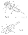
- FIG. 62 is a top, back and right side perspective view of an instrument used to cut keel slots.
- FIG. 63 is a top, front and right side perspective view of the cutting tool depicted in FIG. 62 .
- FIG. 64 is a top, front and right side perspective view of an alternative cutting tool for use with the instrument depicted in FIG. 62 .
- FIGS. 1-4 a first component 10 of an intervertebral implant for total disc replacement according to the present invention is depicted in FIGS. 1-4 .
- the implant including component 10 is primarily designed for insertion between adjacent vertebrae from an anterior direction.
- anterior and posterior directions for convenience.
- terms such as front/back, forward/rearward, left/right and top/bottom may be used to identify directions as depicted in the figures and/or as the implant is used relative to any insertion direction, even though the “front” may be facing anteriorly or posteriorly depending on the direction of insertion used.
- these terms are used for illustration purposes only and not as limiting terms for the invention.
- implant component 10 is formed of an endplate 12 having an outer surface 14 and an integral keel 16 extending outwardly away from outer surface 14 .
- Outer surface 14 is designed to engage an adjacent vertebra, with integral keel 16 then being located in a slot suitably formed in the vertebra (see FIG. 11 for an illustration of a vertebra having a component mounted therein).
- Component 10 also includes an inner surface 18 in which an insert 20 is securely located.
- Insert 20 includes in this embodiment a concavity 22 therein, but it will be appreciated that insert 20 could instead have a convexity. Received in concavity 22 will be a mating component of the implant, allowing a ball joint movement of a similar endplate engaging an adjacent vertebra.
- the similar endplate could have a mating convexity provided thereon, either integrally formed or as an insert (like insert 20 ); or alternatively the similar endplate could be part of a substantially identical component, and a third component could be interposed between the two components to provide articulation between the facing concavities (or convexities) of the components.
- Component 10 is designed to help overcome the problem of artifacts which arises when an MRI is taken of a metal orthopedic medical device such as an intervertebral implant typically having two such components.
- MRI is a standard diagnostic tool used to determine the state of the anatomy by visualizing the soft tissue and nerve roots relative to the bony anatomy.
- commonly used metals for orthopedic devices cause MRI artifacts of different degrees.
- the amount of imaging artifact is reduced as the density of the material and magnetic properties of the material are decreased.
- the following biomedical materials create imaging artifacts in decreasing order: stainless steel, CoCr alloy, Titanium alloy, ceramics and plastic polymer materials.
- component 10 is made to have a reduced amount of imaging artifact, and is thus comprised of two materials: a soft low density material with properties similar to that of the surrounding bone as the main construct foundation, and a harder dense material insert with superior wear properties for the articulating surface areas or parts.
- component 10 includes endplate 12 made of a titanium or titanium alloy, and insert 20 made of a material with good articulating properties such as Co—Cr. It will also be noted that insert 20 is reduced to a small area defining the articulating surface of the implant, further helping to reduce the MRI artifact problem.
- insert 20 is a shrink-fit into a cylindrical portion 24 of a receiving and mating cavity 26 of endplate 12 located adjacent inner surface 18 , though other ways to secure insert 20 as known in the art are possible (such as a sliding/locking ledge design, threads, adhesives, soldering, pressing, etc.).
- the receiving cavity 26 of endplate 12 has been optionally designed to pass through outer surface 18 , so that a portion of insert 20 is viewable and flat with outer surface 18 as shown in FIG. 2 .
- FIGS. 5-8 Depicted in FIGS. 5-8 is an alternative embodiment of a component 10 ′ which is broadly similar to component 10 and whose similar elements will thus be identified with the same reference numerals followed by a prime (′).
- insert 20 ′ has a wide flat bottom 28 (as shown best in FIG. 7 , for example) which mates with the similar shape of cavity 26 ′.
- This bottom 28 is used to secure insert 20 ′ to endplate 12 ′ by use of a suitable adhesive or the like, while the cylindrical areas 30 on the sides of insert 20 ′ in cavity 26 ′ are slightly spaced from the surrounding metal of cylindrical portion 24 ′ of endplate 12 ′ to create an air channel 25 between the two as shown.
- cavity 26 ′ does not extend through to outer surface 14 ′, as shown in FIG. 6 .
- a layer of Co—Cr, ceramic, carbon or other biocompatible low-friction material could also be plasma coated and/or sputtered onto the low-density material of an endplate in a position thereof providing the articulating area (ball and/or socket). This layer of material can then be ground, polished, and/or treated to create the desired low-friction, low-wear articulating surfaces.
- titanium base could be PEEK, PEKK, or some other structural polymer, carbon reinforced or other similar composite materials, or any other low density structural biomaterial.
- a possible alternative could be a pyrrolitic carbon implant with a smooth articulating surface and roughened bone contacting surfaces similar to that used in hand and wrist implants.
- the concept is to create a significantly reduced angled/inclined surface to the forward (or posterior) edge of the keel, more pronounced than the large chamfer at the forward end of the keel such as shown in U.S. Pat. No. 7,204,852 which is designed instead for easier insertion of the keel.
- component 36 has a keel 38 with a front edge formed as a pointed edge 40 (or knife edge shape). With pointed edge 40 , keel 38 can easily cleave through any excess material located in the bottom end of the channel in the vertebra.
- pointed edge 40 keel 38 can easily cleave through any excess material located in the bottom end of the channel in the vertebra.
- a similar solution would be to reduce the length of the keel by increasing the distance between the posterior (forward) face of the keel and the posterior (bottom) edge of the component.
- the depth (bottom) of the clearance cut preparation in the bone of the channel for the keel would then remain the same, but the anterior to posterior (or trailing to leading) length of the keel would be reduced on the posterior (forward or leading) end. Doing this would create added clearance between the bone material left in the channel and the posterior (forward) surface of the keel.
- component 44 has a keel 46 with a forward U-shape, and preferably an overall an H-shape in plan view.
- This U-shape can be provided by removing remove material out of the central forward portion of keel 46 so as to create a slot 48 that goes down the front of keel 46 . Any obstructive bone material in the channel would fill into the slot 48 and allow keel 46 to fully seat in the formed channel.
- an anterior (rearward) top (outer) corner 52 of a keel may be proud or protruding out from the anterior (rearward) surface 54 of the bone as shown in FIG. 11 .
- This exposed metal corner can cause irritation in surrounding tissue.
- a means for slightly reducing the anterior (rearward) corner profile in the keel in the anterior (rearward) end (as well as posterior end, if desired, as noted above) is desirable.
- One means for slightly reducing the anterior (rearward) corner profile in the keel at the anterior end is to provide a component 58 with a keel 60 in which the anterior (rearward) corner is reduced by a curved rounded surface 62 as shown in FIG. 12 .
- Another means for slightly reducing the anterior (rearward) corner profile in the keel at the anterior (rearward) end is to provide a component 64 with a keel 66 in which the anterior (rearward) corner is reduced by a chamfer 68 as shown in FIG. 13 .
- FIGS. 15-16 One means for offsetting keels in adjacent implants is depicted in FIGS. 15-16 .
- an implant 80 has a single central keel 80 on one (superior) endplate 82 and double laterally offset keels 84 on the other (inferior) endplate 86 .
- the positions of double keels could instead be superior, if desired.
- the desired result of a stronger vertebra is as shown in FIG. 16 where such an implant is used both above and below the depicted vertebra.
- double keel receiving channels 90 in the superior side of vertebra 92 which are on either side (laterally offset) from single keel receiving channel 94 in the inferior side of vertebra 92 —leaving a larger amount of bone in the central area of vertebra 92 .
- the two components of an implant could have oppositely offset keels 98 a and 98 b as depicted in FIG. 17 .
- offset keels 84 ′ are divergent at a certain angle as shown in FIG. 18
- offset keels 84 ′′ are convergent as shown in FIG. 19 .
- the enhanced benefit of having divergent/convergent keel designs is to prevent loosening of the associated endplate with that type of geometry.
- the divergent or convergent angles of the keels would add greater resistance to movement in the axial direction and become less likely to be loosened over time.
- FIGS. 20-21 Depicted in FIGS. 20-21 is an implant component 100 having an endplate 102 and insert 104 .
- a raised plate edge or shelf-like feature 106 Provided at the anterior (outer) end of component 102 is a raised plate edge or shelf-like feature 106 .
- the presence of raised edge 106 serves as a means for retarding bone growth/formation between the adjacent vertebrae by its presence and large distance which must then be bridged.
- this raised anterior edge 106 of endplate 104 is preferably polished to a smooth surface finish.
- the raised anterior edge 106 is treated with a suitable surface coating since bone fusion is usually related to the blood supply and cell formation/cell growth for a given area.
- an anti-cellular coating could be placed in this area to prevent bone forming and hence undesirable bone fusion.
- an anti-blood coagulating surface or agent could be integral to raised edge 106 .
- Raised edge 106 could also be designed to hold cement or other material that would contain an anti-coagulant or anti-cellular growth inhibiting agent.
- the bone cement, implant coating, and/or implant edge fusion block feature could also contain a controlled release anti-inflammatory agent to retard the healing process and thus retard bone growth in that area of undesired fusion.
- the keel or other fixation feature of an implant could also be modular as depicted in FIGS. 22-24 .
- the endplate is placed into the intervertebral space first; and then the fixation element, such as a keel, is moved through the plate into a mating slot provided in the bone. Finally, that fixation element is then locked to the plate by a suitable mechanical means such as a fastener or set screw.
- a suitable mechanical means such as a fastener or set screw.
- Keel 116 has a “ball” shape at one end, with the vertebra thus having a cutout or slot designed to receive this ball shape. With this shape, keel 116 is more stably held in place longitudinally, without removing so much of the vertebrae.
- keel geometries or configurations are possible, such as the “Xmas Tree” shape of keel 116 ′ of component 110 ′ depicted in FIG. 23 , or the snake-shaped keel 116 ′′ of component 110 ′′ depicted in FIG. 24 . It would also be alternatively possible to put the keel in place first, and then attach the endplate to the keel in a similar manner.
- the shape of the keel can be slightly wedged in one dimension (in the forward or insertion direction) as shown by keel 122 in FIG. 25 (or keel 126 in FIG. 27 ); or in two dimensions as shown by keel 124 in FIG. 26 .
- the wedge shape is regular and symmetrical, but it could also be irregular and unsymmetrical.
- the wedge shape can go over the whole length of the keel or just in a short section of the keel.
- keel 126 The wedge shape of the keel does not need to be solid, and thus could be hollow as shown by keel 126 in FIG. 27 .
- keel 126 is open from the top, and from the anterior (outer) end; and in another embodiment the keel could also be open from the front (forward end) as shown schematically by keels 128 in FIG. 28 .
- Keel 126 or 128 could also be open from the sides as desired; and it will be thus appreciated that combinations of different openings are also possible.
- a keel with steps is also desirable, as shown by keels 130 , 132 and 134 shown in respective FIGS. 29, 30 and 31 .
- keel 130 it consists of respective small parts 130 ′ that are grouped together to build the keel-shape.
- keel 134 also provides special surfaces preventing the backing out by the keel, namely angled out fin or surface 134 ′ and angled in surface 134 ′′, even though keel 134 is easy to insert in one (forward) direction as surface 134 ′ has a ramping action in that direction.
- the vertical cross-sectional shape of a keel is typically a simple rectangular shape, the vertical cross-sectional geometry of a keel could also be modified to enhance fixation and/or stability in the bone.
- This cross section can vary, as it can be symmetrical or asymmetrical.
- FIG. 32 bowed on each side
- FIG. 33 angled asymmetrically on each top side
- FIG. 34 pointed at the top side
- FIG. 35 angled to one side
- FIG. 36 top edge angled
- FIG. 37 right angle triangle shaped
- FIG. 38 round nosed
- FIG. 39 one side inwardly angled
- FIG. 40 one side inwardly bowed
- FIG. 41 both sides inwardly bowed
- FIG. 42 top edge angled to one side which is angled inward;
- FIG. 43 angled on each top side, and each side angled inward;
- FIG. 44 both sides angled inward
- FIG. 45 both sides angled outward
- FIG. 46 diamond shaped
- FIG. 47 both ends chamfered
- FIG. 48 parallelogram shaped
- FIG. 49 elongated hexagonal shaped
- FIG. 50 both ends stepped at both sides;
- FIG. 51 elongated pentagon shaped.
- the horizontal cross-sectional shape of a keel is also typically a simple rectangular shape
- the horizontal cross-sectional geometry of a keel could also be modified to enhance fixation and/or stability in the bone.
- This cross section can vary, as it can be symmetrical or asymmetrical.
- FIG. 52 angled symmetrically toward the leading edge
- FIG. 53 angled symmetrically toward the leading edge to a point
- FIG. 54 rounded leading edge
- FIG. 55 sharply angled to one side leading edge
- FIG. 56 a series of angled leading edges
- FIG. 57 diamond shaped with trailing edge blunted
- FIG. 58 asymmetrically bowed.
- the thicknesses of the keels can vary. Some examples of differing thickness keels are shown in the drawings as described hereafter with reference to the following figures.
- the top keels have a small and a large thickness, while the bottom keel has an intermediate thickness;
- the bottom keels have a small and an intermediate thickness, while the top keel has a large thickness;
- the top keels have a small and a large thickness, while the bottom keels have a small intermediate thickness and a large intermediate thickness.
- FIGS. 62-63 Depicted in FIGS. 62-63 is an instrument broadly similar to those disclosed in the above noted published applications, and thus including a trial implant 150 having an adjustable stop 152 .
- the trial implant 150 includes a top slot 154 at the location above which a keel slot is to be cut in a superior (or inferior) vertebra when trial implant 150 is located between two vertebrae. It will be noted that trial implant also has two bottom slots (not shown) similar to top slot 150 , but at locations where offset keel slots are to be cut in the inferior vertebra—so that trial implant 150 is thus used to cut the slots for an implant such as disclosed in FIG. 15 .
- a guide 156 Extending away from trial implant 150 is a guide 156 which is used to guide trial implant into the intervertebral space between two adjacent vertebrae after the disc is removed and to which adjustable stop 152 is threadedly engaged.
- Guide 156 has slots corresponding to those in trial implant 150 , such as top slot 158 .
- Slots 154 and 158 serve to guide saw cutting tool 160 therealong, where cutting tool 160 is rapidly reciprocated by a suitable motor 162 shown schematically and which can take the form of various power tools as known in the art. Rapid reciprocation of saw cutting tool 160 is effective to produce is a reduced impact on the vertebral bone due to the acceleration to mass relationship between cutting tool 160 and the vertebral bone.
- cutting tool 160 includes three thin saw blades 162 which extend at a proximal edge thereof along slots in guide 156 and trial implant 150 , such as slots 158 and 154 . At the distal edge, saw blades 162 have suitable cutting teeth 164 , which at a leading or forward end form a ramp for easier starting into the vertebra. The insertion depth of cutting blades into the vertebrae is controlled by adjusting the position of adjustable stop 152 .
- cutting tool 160 has been shown with three blades, it will be appreciated that only a single blade could be provided to cut each slot individually as needed. It would also be possible to provide a blade more like a chisel but with cutting teeth just at the front. Different interchangeable blades would also be possible, if a narrower or wider, or higher or lower, or deeper or shallower, cut slot was desired. If desired, motor 162 can be dispensed with, and the blade or blades moved by hand with the same guidance.
- the material of the blades is preferably a suitable metal, but ceramic or plastic blades, or even a diamond cutting blade, would also be possible. If desired or necessary, a coatings to reduce friction could be used with the cutting blades.
- Cutting tool 168 includes chisel blades 170 and would thus be used to chisel three slots simultaneously.
Abstract
Description
Claims (18)
Priority Applications (4)
| Application Number | Priority Date | Filing Date | Title |
|---|---|---|---|
| US14/643,287 US9387086B2 (en) | 2006-07-24 | 2015-03-10 | Intervertebral implant with keel |
| US15/182,163 US9883950B2 (en) | 2006-07-24 | 2016-06-14 | Intervertebral implant with keel |
| US15/888,505 US10583014B2 (en) | 2006-07-24 | 2018-02-05 | Intervertebral implant with keel |
| US16/812,674 US11690728B2 (en) | 2006-07-24 | 2020-03-09 | Intervertebral implant with keel |
Applications Claiming Priority (4)
| Application Number | Priority Date | Filing Date | Title |
|---|---|---|---|
| US83259506P | 2006-07-24 | 2006-07-24 | |
| PCT/US2007/074218 WO2008014258A2 (en) | 2006-07-24 | 2007-07-24 | Intervertebral implant with keel |
| US37507109A | 2009-11-20 | 2009-11-20 | |
| US14/643,287 US9387086B2 (en) | 2006-07-24 | 2015-03-10 | Intervertebral implant with keel |
Related Parent Applications (2)
| Application Number | Title | Priority Date | Filing Date |
|---|---|---|---|
| US12/375,071 Continuation US8998990B2 (en) | 2006-07-24 | 2007-07-24 | Intervertebral implant with keel |
| PCT/US2007/074218 Continuation WO2008014258A2 (en) | 2006-07-24 | 2007-07-24 | Intervertebral implant with keel |
Related Child Applications (2)
| Application Number | Title | Priority Date | Filing Date |
|---|---|---|---|
| US15/182,163 Continuation US9883950B2 (en) | 2006-07-24 | 2016-06-14 | Intervertebral implant with keel |
| US15/888,505 Continuation US10583014B2 (en) | 2006-07-24 | 2018-02-05 | Intervertebral implant with keel |
Publications (2)
| Publication Number | Publication Date |
|---|---|
| US20150182345A1 US20150182345A1 (en) | 2015-07-02 |
| US9387086B2 true US9387086B2 (en) | 2016-07-12 |
Family
ID=38982262
Family Applications (5)
| Application Number | Title | Priority Date | Filing Date |
|---|---|---|---|
| US12/375,071 Active - Reinstated 2030-05-29 US8998990B2 (en) | 2006-07-24 | 2007-07-24 | Intervertebral implant with keel |
| US14/643,287 Active US9387086B2 (en) | 2006-07-24 | 2015-03-10 | Intervertebral implant with keel |
| US15/182,163 Active US9883950B2 (en) | 2006-07-24 | 2016-06-14 | Intervertebral implant with keel |
| US15/888,505 Active US10583014B2 (en) | 2006-07-24 | 2018-02-05 | Intervertebral implant with keel |
| US16/812,674 Active 2029-01-17 US11690728B2 (en) | 2006-07-24 | 2020-03-09 | Intervertebral implant with keel |
Family Applications Before (1)
| Application Number | Title | Priority Date | Filing Date |
|---|---|---|---|
| US12/375,071 Active - Reinstated 2030-05-29 US8998990B2 (en) | 2006-07-24 | 2007-07-24 | Intervertebral implant with keel |
Family Applications After (3)
| Application Number | Title | Priority Date | Filing Date |
|---|---|---|---|
| US15/182,163 Active US9883950B2 (en) | 2006-07-24 | 2016-06-14 | Intervertebral implant with keel |
| US15/888,505 Active US10583014B2 (en) | 2006-07-24 | 2018-02-05 | Intervertebral implant with keel |
| US16/812,674 Active 2029-01-17 US11690728B2 (en) | 2006-07-24 | 2020-03-09 | Intervertebral implant with keel |
Country Status (5)
| Country | Link |
|---|---|
| US (5) | US8998990B2 (en) |
| EP (2) | EP2043563B1 (en) |
| AU (1) | AU2007276755A1 (en) |
| CA (1) | CA2658876C (en) |
| WO (1) | WO2008014258A2 (en) |
Cited By (1)
| Publication number | Priority date | Publication date | Assignee | Title |
|---|---|---|---|---|
| US20140309640A1 (en) * | 2009-05-29 | 2014-10-16 | Smith & Nephew, Inc. | Methods and apparatus for performing knee arthroplasty |
Families Citing this family (82)
| Publication number | Priority date | Publication date | Assignee | Title |
|---|---|---|---|---|
| CA2391330C (en) | 1999-07-02 | 2008-11-18 | Spine Solutions Inc. | Intervertebral implant |
| AR038680A1 (en) | 2002-02-19 | 2005-01-26 | Synthes Ag | INTERVERTEBRAL IMPLANT |
| EP2335656B1 (en) | 2003-02-06 | 2012-09-05 | Synthes GmbH | Implant between vertebrae |
| US7491204B2 (en) | 2003-04-28 | 2009-02-17 | Spine Solutions, Inc. | Instruments and method for preparing an intervertebral space for receiving an artificial disc implant |
| US7854766B2 (en) * | 2004-05-13 | 2010-12-21 | Moskowitz Nathan C | Artificial total lumbar disc for unilateral safe and simple posterior placement in the lumbar spine, and removable bifunctional screw which drives vertical sliding expansile plate expansion, and interplate widening, and angled traction spikes |
| EP1773256B1 (en) | 2004-06-30 | 2019-11-27 | Synergy Disc Replacement Inc. | Artificial spinal disc |
| EP1988855A2 (en) | 2006-02-27 | 2008-11-12 | Synthes GmbH | Intervertebral implant with fixation geometry |
| US8409290B2 (en) * | 2006-03-08 | 2013-04-02 | Seaspine, Inc. | Interbody device for spinal applications |
| WO2008014258A2 (en) | 2006-07-24 | 2008-01-31 | Spine Solutions, Inc. | Intervertebral implant with keel |
| KR20090049054A (en) | 2006-07-31 | 2009-05-15 | 신세스 게엠바하 | Drilling/milling guide and keel cut preparation system |
| US20080228275A1 (en) * | 2007-03-14 | 2008-09-18 | Heather Cannon | Intervertebral implant component with three points of contact |
| US9820861B2 (en) | 2007-10-09 | 2017-11-21 | Richard Charles Smith | Rail-fixing implant |
| US9486321B1 (en) * | 2007-10-09 | 2016-11-08 | Richard C. Smith | Wedge-fixing implant |
| US8758441B2 (en) * | 2007-10-22 | 2014-06-24 | Spinalmotion, Inc. | Vertebral body replacement and method for spanning a space formed upon removal of a vertebral body |
| AU2008316600B2 (en) | 2007-10-25 | 2014-09-18 | Jeffery D. Arnett | Systems and methods for vertebral disc replacement |
| BRPI0820172A2 (en) | 2007-11-16 | 2015-06-16 | Synthes Gmbh | Low Profile Intervertebral Implant |
| US8328872B2 (en) | 2008-09-02 | 2012-12-11 | Globus Medical, Inc. | Intervertebral fusion implant |
| US8709083B2 (en) | 2009-06-04 | 2014-04-29 | William E. Duffield | Intervertebral fusion implant |
| CA2742812A1 (en) | 2008-11-07 | 2010-05-14 | William P. Mcdonough | Zero-profile interbody spacer and coupled plate assembly |
| PL2358309T3 (en) | 2008-12-18 | 2016-04-29 | 4 Web Inc | Truss implant |
| EP2419053B1 (en) * | 2009-04-15 | 2015-04-08 | Synthes GmbH | Trial implant assembly |
| US8657820B2 (en) * | 2009-10-12 | 2014-02-25 | Tornier, Inc. | Bone plate and keel systems |
| US9480511B2 (en) | 2009-12-17 | 2016-11-01 | Engage Medical Holdings, Llc | Blade fixation for ankle fusion and arthroplasty |
| US8814872B2 (en) * | 2010-03-16 | 2014-08-26 | Arthrex, Inc. | Double row keel cut saw blade |
| US9155631B2 (en) | 2010-04-08 | 2015-10-13 | Globus Medical Inc. | Intervertbral implant |
| US20110313532A1 (en) * | 2010-06-18 | 2011-12-22 | Jessee Hunt | Bone implant interface system and method |
| WO2012083205A1 (en) | 2010-12-16 | 2012-06-21 | Medicinelodge, Inc. Dba Imds Co-Innovation | Arthroplasty systems and methods |
| EP2654626B1 (en) | 2010-12-21 | 2016-02-24 | Synthes GmbH | Intervertebral implants and systems |
| US9241809B2 (en) | 2010-12-21 | 2016-01-26 | DePuy Synthes Products, Inc. | Intervertebral implants, systems, and methods of use |
| US8998991B2 (en) * | 2011-02-23 | 2015-04-07 | Globus Medical, Inc. | Six degree spine stabilization devices and methods |
| US9848994B2 (en) | 2011-09-16 | 2017-12-26 | Globus Medical, Inc. | Low profile plate |
| US10245155B2 (en) | 2011-09-16 | 2019-04-02 | Globus Medical, Inc. | Low profile plate |
| US10881526B2 (en) | 2011-09-16 | 2021-01-05 | Globus Medical, Inc. | Low profile plate |
| US9237957B2 (en) | 2011-09-16 | 2016-01-19 | Globus Medical, Inc. | Low profile plate |
| US9681959B2 (en) | 2011-09-16 | 2017-06-20 | Globus Medical, Inc. | Low profile plate |
| US9149365B2 (en) | 2013-03-05 | 2015-10-06 | Globus Medical, Inc. | Low profile plate |
| US9539109B2 (en) | 2011-09-16 | 2017-01-10 | Globus Medical, Inc. | Low profile plate |
| US9017410B2 (en) * | 2011-10-26 | 2015-04-28 | Globus Medical, Inc. | Artificial discs |
| US9254130B2 (en) | 2011-11-01 | 2016-02-09 | Hyun Bae | Blade anchor systems for bone fusion |
| US9615856B2 (en) | 2011-11-01 | 2017-04-11 | Imds Llc | Sacroiliac fusion cage |
| US10238382B2 (en) | 2012-03-26 | 2019-03-26 | Engage Medical Holdings, Llc | Blade anchor for foot and ankle |
| US20130325071A1 (en) | 2012-05-30 | 2013-12-05 | Marcin Niemiec | Aligning Vertebral Bodies |
| US9326861B2 (en) | 2012-08-03 | 2016-05-03 | Globus Medical, Inc. | Stabilizing joints |
| CN104780870B (en) | 2012-09-25 | 2018-03-02 | 4网络公司 | Programmable implant and the method for repairing bone structure using programmable implant |
| US10105239B2 (en) | 2013-02-14 | 2018-10-23 | Globus Medical, Inc. | Devices and methods for correcting vertebral misalignment |
| US9585765B2 (en) | 2013-02-14 | 2017-03-07 | Globus Medical, Inc | Devices and methods for correcting vertebral misalignment |
| US10117754B2 (en) | 2013-02-25 | 2018-11-06 | Globus Medical, Inc. | Expandable intervertebral implant |
| US9539103B2 (en) | 2013-03-15 | 2017-01-10 | Globus Medical, Inc. | Expandable intervertebral implant |
| US9456906B2 (en) | 2013-03-15 | 2016-10-04 | Globus Medical, Inc. | Expandable intervertebral implant |
| US9572677B2 (en) | 2013-03-15 | 2017-02-21 | Globus Medical, Inc. | Expandable intervertebral implant |
| US9034045B2 (en) | 2013-03-15 | 2015-05-19 | Globus Medical, Inc | Expandable intervertebral implant |
| US9186258B2 (en) | 2013-03-15 | 2015-11-17 | Globus Medical, Inc. | Expandable intervertebral implant |
| US9149367B2 (en) | 2013-03-15 | 2015-10-06 | Globus Medical Inc | Expandable intervertebral implant |
| US9636226B2 (en) | 2013-03-15 | 2017-05-02 | 4Web, Inc. | Traumatic bone fracture repair systems and methods |
| US9233009B2 (en) | 2013-03-15 | 2016-01-12 | Globus Medical, Inc. | Expandable intervertebral implant |
| WO2014143740A1 (en) * | 2013-03-15 | 2014-09-18 | Mako Surgical Corp. | Unicondylar tibial knee implant |
| US9655735B2 (en) * | 2013-03-15 | 2017-05-23 | Atlas Spine, Inc. | Spinal disc prosthesis |
| US9474622B2 (en) | 2013-03-15 | 2016-10-25 | Globus Medical, Inc | Expandable intervertebral implant |
| US10507119B2 (en) * | 2013-12-19 | 2019-12-17 | Aesculap Implant Systems, Llc | Spinal interbody device, system and method |
| US9545320B2 (en) | 2014-05-15 | 2017-01-17 | Globus Medical, Inc. | Standalone interbody implants |
| US9675465B2 (en) | 2014-05-15 | 2017-06-13 | Globus Medical, Inc. | Standalone interbody implants |
| US9968461B2 (en) | 2014-05-15 | 2018-05-15 | Globus Medical, Inc. | Standalone interbody implants |
| US11160666B2 (en) | 2014-05-15 | 2021-11-02 | Globus Medical, Inc. | Laterally insertable intervertebral spinal implant |
| US9486327B2 (en) | 2014-05-15 | 2016-11-08 | Globus Medical, Inc. | Standalone interbody implants |
| US10105240B2 (en) * | 2014-08-19 | 2018-10-23 | Oxford Performance Materials, Inc. | Spinal implant and method for fabricating the same |
| US9867718B2 (en) | 2014-10-22 | 2018-01-16 | DePuy Synthes Products, Inc. | Intervertebral implants, systems, and methods of use |
| WO2016210434A1 (en) * | 2015-06-25 | 2016-12-29 | Institute for Musculoskeletal Science and Education, Ltd. | Interbody fusion device and system for implantation |
| US10034768B2 (en) | 2015-09-02 | 2018-07-31 | Globus Medical, Inc. | Implantable systems, devices and related methods |
| US10390955B2 (en) | 2016-09-22 | 2019-08-27 | Engage Medical Holdings, Llc | Bone implants |
| US10231849B2 (en) | 2016-10-13 | 2019-03-19 | Warsaw Orthopedic, Inc. | Surgical instrument system and method |
| US10307265B2 (en) | 2016-10-18 | 2019-06-04 | Institute for Musculoskeletal Science and Education, Ltd. | Implant with deployable blades |
| US11540928B2 (en) | 2017-03-03 | 2023-01-03 | Engage Uni Llc | Unicompartmental knee arthroplasty |
| US10456272B2 (en) | 2017-03-03 | 2019-10-29 | Engage Uni Llc | Unicompartmental knee arthroplasty |
| US11452608B2 (en) | 2017-04-05 | 2022-09-27 | Globus Medical, Inc. | Decoupled spacer and plate and method of installing the same |
| US10376385B2 (en) | 2017-04-05 | 2019-08-13 | Globus Medical, Inc. | Decoupled spacer and plate and method of installing the same |
| US11439440B2 (en) * | 2019-06-30 | 2022-09-13 | Innovasis, Inc. | Vertebral disc repair |
| USD948052S1 (en) * | 2019-10-07 | 2022-04-05 | L&K Biomed Co., Ltd. | Part of spinal fusion cage |
| US11197765B2 (en) | 2019-12-04 | 2021-12-14 | Robert S. Bray, Jr. | Artificial disc replacement device |
| US11839554B2 (en) | 2020-01-23 | 2023-12-12 | Robert S. Bray, Jr. | Method of implanting an artificial disc replacement device |
| AU2021204625A1 (en) * | 2020-07-06 | 2022-01-20 | Howmedica Osteonics Corp. | Anatomic implant for joints |
| CN111920551A (en) * | 2020-07-28 | 2020-11-13 | 北京市春立正达医疗器械股份有限公司 | Primary total ankle joint prosthesis |
| US20220202584A1 (en) * | 2020-12-29 | 2022-06-30 | Brigham Young University (Byu) | Artificial vertebral endplates and associated methods |
Citations (322)
| Publication number | Priority date | Publication date | Assignee | Title |
|---|---|---|---|---|
| US114816A (en) | 1871-05-16 | Improvement in carriage-jacks | ||
| US2854981A (en) * | 1957-02-18 | 1958-10-07 | Orthopedic Frame Company | Surgical instrument |
| US3320951A (en) | 1964-04-21 | 1967-05-23 | Wittebol Paul | Intramedullary prostheses |
| US3486505A (en) | 1967-05-22 | 1969-12-30 | Gordon M Morrison | Orthopedic surgical instrument |
| US3510883A (en) | 1967-10-30 | 1970-05-12 | Robert F Cathcart | Joint prosthesis |
| US3579829A (en) | 1970-01-22 | 1971-05-25 | Sampson Corp | Pericortical dental implant and inserter therefor |
| US3740769A (en) | 1971-02-11 | 1973-06-26 | E Haboush | Prosthesis for hip joints |
| DE2263842A1 (en) | 1972-12-28 | 1974-07-04 | Hoffmann Daimler Siegfried Dr | DISC PROTHESIS |
| US3875595A (en) | 1974-04-15 | 1975-04-08 | Edward C Froning | Intervertebral disc prosthesis and instruments for locating same |
| US3903549A (en) | 1974-06-12 | 1975-09-09 | William Minor Deyerle | Acetabular cup prosthesis component for total or subtotal hip prosthesis system |
| US3992726A (en) | 1974-08-07 | 1976-11-23 | National Research Development Corporation | Endoprosthetic bone joint devices |
| USD243286S (en) | 1975-06-02 | 1977-02-01 | William Minor Deyerle | Femoral hip prosthesis component for total and sub-total hip replacement systems |
| US4021864A (en) | 1976-04-14 | 1977-05-10 | The Regents Of The University Of California | Ankle prosthesis |
| US4034746A (en) | 1975-08-01 | 1977-07-12 | Williams Robert W | Retractor |
| US4038987A (en) | 1974-02-08 | 1977-08-02 | Olympus Optical Co., Ltd. | Forceps device for endoscope |
| US4038897A (en) | 1975-10-14 | 1977-08-02 | Electronic Music Laboratories, Inc. | Electronic music system and stringed instrument input device therefor |
| DE2804936A1 (en) | 1978-02-01 | 1979-08-02 | Sulzer Ag | INTER-SPINE PROSTHESIS |
| US4232404A (en) | 1977-07-18 | 1980-11-11 | National Research Development Corporation | Endoprosthetic ankle joint |
| US4309777A (en) | 1980-11-13 | 1982-01-12 | Patil Arun A | Artificial intervertebral disc |
| DE3023353C2 (en) | 1979-10-03 | 1982-04-22 | Gebrüder Sulzer AG, 8401 Winterthur | Total intervertebral prosthesis |
| US4349921A (en) | 1980-06-13 | 1982-09-21 | Kuntz J David | Intervertebral disc prosthesis |
| EP0077159A1 (en) | 1981-10-14 | 1983-04-20 | Brian Norman Atkins | Vertebrae spreader |
| US4467802A (en) | 1980-03-31 | 1984-08-28 | Harald Maslanka | Surgical gripping instrument |
| US4470158A (en) | 1978-03-10 | 1984-09-11 | Biomedical Engineering Corp. | Joint endoprosthesis |
| US4545374A (en) | 1982-09-03 | 1985-10-08 | Jacobson Robert E | Method and instruments for performing a percutaneous lumbar diskectomy |
| US4550450A (en) | 1984-07-24 | 1985-11-05 | Kinnett James G | Total shoulder prosthesis system |
| US4622959A (en) | 1985-03-05 | 1986-11-18 | Marcus Randall E | Multi-use femoral intramedullary nail |
| DE3526742A1 (en) | 1985-07-26 | 1987-01-29 | Volkmar Dipl Ing Jansson | Guide sleeve with a striker for driving (bone) chips in bone |
| US4653487A (en) | 1986-01-29 | 1987-03-31 | Maale Gerhard E | Intramedullary rod assembly for cement injection system |
| US4681589A (en) | 1984-06-01 | 1987-07-21 | Tronzo Raymond G | Adjustable acetabular cup prosthesis as part of a total cup replacement system |
| US4697586A (en) | 1986-06-24 | 1987-10-06 | Gazale William J | Combined chisel-guide surgical instrument |
| US4714469A (en) | 1987-02-26 | 1987-12-22 | Pfizer Hospital Products Group, Inc. | Spinal implant |
| US4736738A (en) | 1984-07-09 | 1988-04-12 | Matej Lipovsek | Instrument kit and procedure for performing posterior lumbar interbody fusion |
| US4759769A (en) | 1987-02-12 | 1988-07-26 | Health & Research Services Inc. | Artificial spinal disc |
| US4759766A (en) | 1984-09-04 | 1988-07-26 | Humboldt-Universitaet Zu Berlin | Intervertebral disc endoprosthesis |
| US4770661A (en) | 1982-01-18 | 1988-09-13 | Indong Oh | Conversion femoral endoprosthesis |
| USH571H (en) * | 1986-02-20 | 1989-02-07 | The United States Of America As Represented By The Secretary Of The Army | Double-bladed, water-cooled attachment for surgical bone cutting saw and method for using and assembling the same |
| US4805607A (en) | 1987-12-03 | 1989-02-21 | Boehringer Mannheim Corporation | Modular intramedullary nail system |
| US4819334A (en) * | 1983-05-06 | 1989-04-11 | Minnesota Mining And Manufacturing Company | Orbital saw device |
| US4863476A (en) | 1986-08-29 | 1989-09-05 | Shepperd John A N | Spinal implant |
| US4874389A (en) | 1987-12-07 | 1989-10-17 | Downey Ernest L | Replacement disc |
| US4875474A (en) | 1988-01-29 | 1989-10-24 | Biomet, Inc. | Variable wall thickness interlocking intramedullary nail |
| US4892545A (en) | 1988-07-14 | 1990-01-09 | Ohio Medical Instrument Company, Inc. | Vertebral lock |
| US4932975A (en) | 1989-10-16 | 1990-06-12 | Vanderbilt University | Vertebral prosthesis |
| US4936853A (en) | 1989-01-11 | 1990-06-26 | Kirschner Medical Corporation | Modular knee prosthesis |
| US4936863A (en) | 1988-05-13 | 1990-06-26 | Hofmann Aaron A | Hip prosthesis |
| US4946378A (en) | 1987-11-24 | 1990-08-07 | Asahi Kogaku Kogyo Kabushiki Kaisha | Artificial intervertebral disc |
| US4986826A (en) * | 1987-01-29 | 1991-01-22 | Roger Gregory J | Method and apparatus for removing prosthetic cement |
| US4997432A (en) | 1988-03-23 | 1991-03-05 | Waldemar Link Gmbh & Co. | Surgical instrument set |
| US5004476A (en) | 1989-10-31 | 1991-04-02 | Tulane University | Porous coated total hip replacement system |
| US5022576A (en) | 1989-01-13 | 1991-06-11 | Jenq Jin Huoo | Lever-operated protective cover for a saw tooth-shaped cutter |
| US5035698A (en) * | 1985-04-10 | 1991-07-30 | Ohio Medical Instrument Co., Inc. | Arcuate osteotomy blade |
| US5037438A (en) | 1989-07-25 | 1991-08-06 | Richards Medical Company | Zirconium oxide coated prosthesis for wear and corrosion resistance |
| WO1991013598A1 (en) | 1990-03-07 | 1991-09-19 | J.B.S. S.A. | Prosthesis for intervertebral discs and instruments for its implantation |
| US5062850A (en) | 1990-01-16 | 1991-11-05 | University Of Florida | Axially-fixed vertebral body prosthesis and method of fixation |
| US5071437A (en) | 1989-02-15 | 1991-12-10 | Acromed Corporation | Artificial disc |
| US5108442A (en) | 1991-05-09 | 1992-04-28 | Boehringer Mannheim Corporation | Prosthetic implant locking assembly |
| US5122142A (en) * | 1990-09-13 | 1992-06-16 | Hall Surgical Division Of Zimmer, Inc. | Irrigating saw blade |
| US5171280A (en) | 1990-04-20 | 1992-12-15 | Sulzer Brothers Limited | Intervertebral prosthesis |
| US5192327A (en) | 1991-03-22 | 1993-03-09 | Brantigan John W | Surgical prosthetic implant for vertebrae |
| US5211645A (en) | 1989-07-04 | 1993-05-18 | Rainer Baumgart | Device for guiding an internal saw for long tubular bone osteotomy |
| US5228455A (en) | 1991-05-20 | 1993-07-20 | Siemens Pacesetter, Inc. | Implant tool for extendable/retractable positive fixation lead |
| US5236460A (en) | 1990-02-12 | 1993-08-17 | Midas Rex Pneumatic Tools, Inc. | Vertebral body prosthesis |
| US5258031A (en) | 1992-01-06 | 1993-11-02 | Danek Medical | Intervertebral disk arthroplasty |
| US5271737A (en) | 1992-09-04 | 1993-12-21 | U.S. Medical Products, Inc. | Tibial prosthetic implant with offset stem |
| US5282868A (en) | 1991-06-17 | 1994-02-01 | Andre Bahler | Prosthetic arrangement for a complex joint, especially knee joint |
| US5290312A (en) | 1991-09-03 | 1994-03-01 | Alphatec | Artificial vertebral body |
| US5306309A (en) | 1992-05-04 | 1994-04-26 | Calcitek, Inc. | Spinal disk implant and implantation kit |
| US5306308A (en) | 1989-10-23 | 1994-04-26 | Ulrich Gross | Intervertebral implant |
| US5326366A (en) | 1993-02-16 | 1994-07-05 | Wright Medical Technology, Inc. | Biomechanical great toe implant |
| US5336232A (en) | 1991-03-14 | 1994-08-09 | United States Surgical Corporation | Approximating apparatus for surgical jaw structure and method of using the same |
| US5344458A (en) | 1992-08-06 | 1994-09-06 | Bonutti Peter M | Arthroplasty component |
| US5364397A (en) | 1993-06-01 | 1994-11-15 | Zimmer, Inc. | Spinal coupler seater with dual jaws and an independent plunger |
| US5370697A (en) | 1992-04-21 | 1994-12-06 | Sulzer Medizinaltechnik Ag | Artificial intervertebral disk member |
| US5383888A (en) | 1992-02-12 | 1995-01-24 | United States Surgical Corporation | Articulating endoscopic surgical apparatus |
| US5395317A (en) | 1991-10-30 | 1995-03-07 | Smith & Nephew Dyonics, Inc. | Unilateral biportal percutaneous surgical procedure |
| US5401269A (en) | 1992-03-13 | 1995-03-28 | Waldemar Link Gmbh & Co. | Intervertebral disc endoprosthesis |
| US5403318A (en) * | 1993-01-15 | 1995-04-04 | Boehringer Laboratories, Inc. | Apparatus and method for shaping bone |
| US5409492A (en) | 1993-08-09 | 1995-04-25 | Stelkast Incorporated | System for coupling an implant to a tool for inserting and removing the implant |
| US5423825A (en) | 1992-06-10 | 1995-06-13 | Levine; Andrew S. | Spinal fusion instruments and methods |
| US5425773A (en) | 1992-01-06 | 1995-06-20 | Danek Medical, Inc. | Intervertebral disk arthroplasty device |
| US5431658A (en) | 1994-02-14 | 1995-07-11 | Moskovich; Ronald | Facilitator for vertebrae grafts and prostheses |
| US5443514A (en) | 1993-10-01 | 1995-08-22 | Acromed Corporation | Method for using spinal implants |
| US5458641A (en) | 1993-09-08 | 1995-10-17 | Ramirez Jimenez; Juan J. | Vertebral body prosthesis |
| US5484437A (en) | 1988-06-13 | 1996-01-16 | Michelson; Gary K. | Apparatus and method of inserting spinal implants |
| US5489307A (en) | 1993-02-10 | 1996-02-06 | Spine-Tech, Inc. | Spinal stabilization surgical method |
| US5501654A (en) | 1993-07-15 | 1996-03-26 | Ethicon, Inc. | Endoscopic instrument having articulating element |
| US5507821A (en) | 1993-01-21 | 1996-04-16 | Sulzer Medizinaltechnik Ag | Artificial wrist joint |
| US5507816A (en) | 1991-12-04 | 1996-04-16 | Customflex Limited | Spinal vertebrae implants |
| US5509934A (en) | 1992-02-28 | 1996-04-23 | Osteonics Corp. | Prosthetic knee tibial component constructed of synthetic polymeric material |
| FR2718635B1 (en) | 1994-04-15 | 1996-07-05 | Axcyl Medical | Cervical prosthesis. |
| US5534030A (en) | 1993-02-09 | 1996-07-09 | Acromed Corporation | Spine disc |
| US5534029A (en) | 1992-12-14 | 1996-07-09 | Yumiko Shima | Articulated vertebral body spacer |
| US5545229A (en) | 1988-08-18 | 1996-08-13 | University Of Medicine And Dentistry Of Nj | Functional and biocompatible intervertebral disc spacer containing elastomeric material of varying hardness |
| US5554191A (en) | 1994-01-26 | 1996-09-10 | Biomat | Intersomatic vertebral cage |
| US5556431A (en) | 1992-03-13 | 1996-09-17 | B+E,Uml U+Ee Ttner-Janz; Karin | Intervertebral disc endoprosthesis |
| US5562736A (en) | 1994-10-17 | 1996-10-08 | Raymedica, Inc. | Method for surgical implantation of a prosthetic spinal disc nucleus |
| US5571109A (en) | 1993-08-26 | 1996-11-05 | Man Ceramics Gmbh | System for the immobilization of vertebrae |
| US5591235A (en) | 1995-03-15 | 1997-01-07 | Kuslich; Stephen D. | Spinal fixation device |
| FR2724108B1 (en) | 1994-09-02 | 1997-01-17 | Jbs Sa | JOINT PROSTHESIS |
| US5609636A (en) | 1994-05-23 | 1997-03-11 | Spine-Tech, Inc. | Spinal implant |
| US5658347A (en) | 1994-04-25 | 1997-08-19 | Sarkisian; James S. | Acetabular cup with keel |
| US5674296A (en) | 1994-11-14 | 1997-10-07 | Spinal Dynamics Corporation | Human spinal disc prosthesis |
| US5676701A (en) | 1993-01-14 | 1997-10-14 | Smith & Nephew, Inc. | Low wear artificial spinal disc |
| FR2737656B1 (en) | 1995-08-09 | 1997-10-17 | Jbs Sa | IMPACTOR DEVICE FOR PLACING A PROSTHESIS FOR INTERVERTEBRAL DISCS |
| US5683465A (en) | 1996-03-18 | 1997-11-04 | Shinn; Gary Lee | Artificial intervertebral disk prosthesis |
| US5702469A (en) | 1996-01-18 | 1997-12-30 | Kinetikos Medical, Inc. | Thumb joint prosthesis and related method of implantation |
| US5702486A (en) | 1994-02-22 | 1997-12-30 | Kirschner Medical Corporation | Modular humeral prosthesis for reconstruction of the humerus |
| US5716415A (en) | 1993-10-01 | 1998-02-10 | Acromed Corporation | Spinal implant |
| US5720751A (en) | 1996-11-27 | 1998-02-24 | Jackson; Roger P. | Tools for use in seating spinal rods in open ended implants |
| FR2742653B1 (en) | 1995-12-21 | 1998-02-27 | Colorado | INTERSOMATIC VERTEBRAL CAGE |
| US5722977A (en) | 1996-01-24 | 1998-03-03 | Danek Medical, Inc. | Method and means for anterior lumbar exact cut with quadrilateral osteotome and precision guide/spacer |
| US5755811A (en) | 1995-08-25 | 1998-05-26 | Zimmer, Inc. | Prosthetic implant with fins |
| US5755798A (en) | 1995-10-26 | 1998-05-26 | Artos Medizinische Produkte Gmbh | Intervertebral implant |
| US5776199A (en) | 1988-06-28 | 1998-07-07 | Sofamor Danek Properties | Artificial spinal fusion implants |
| US5782832A (en) | 1996-10-01 | 1998-07-21 | Surgical Dynamics, Inc. | Spinal fusion implant and method of insertion thereof |
| US5782830A (en) | 1995-10-16 | 1998-07-21 | Sdgi Holdings, Inc. | Implant insertion device |
| WO1998034552A1 (en) | 1997-02-06 | 1998-08-13 | Surgical Dynamics | Expandable non-threaded spinal fusion device |
| US5797909A (en) | 1988-06-13 | 1998-08-25 | Michelson; Gary Karlin | Apparatus for inserting spinal implants |
| US5800547A (en) | 1994-08-20 | 1998-09-01 | Schafer Micomed Gmbh | Ventral intervertebral implant |
| US5824094A (en) | 1997-10-17 | 1998-10-20 | Acromed Corporation | Spinal disc |
| USD401335S (en) | 1997-07-28 | 1998-11-17 | Tibor Koros | Combined cervical and lumbar extractor and injector surgical instrument |
| US5865848A (en) | 1997-09-12 | 1999-02-02 | Artifex, Ltd. | Dynamic intervertebral spacer and method of use |
| US5885300A (en) | 1996-04-01 | 1999-03-23 | Asahi Kogaku Kogyo Kabushiki Kaisha | Guide apparatus of intervertebral implant |
| US5888226A (en) | 1997-11-12 | 1999-03-30 | Rogozinski; Chaim | Intervertebral prosthetic disc |
| US5895428A (en) | 1996-11-01 | 1999-04-20 | Berry; Don | Load bearing spinal joint implant |
| US5897593A (en) | 1997-03-06 | 1999-04-27 | Sulzer Spine-Tech Inc. | Lordotic spinal implant |
| US5899901A (en) | 1991-05-18 | 1999-05-04 | Middleton; Jeffrey Keith | Spinal fixation system |
| US5899941A (en) | 1997-12-09 | 1999-05-04 | Chubu Bearing Kabushiki Kaisha | Artificial intervertebral disk |
| US5951564A (en) | 1996-12-18 | 1999-09-14 | Bristol-Myers Squibb Company | Orthopaedic positioning apparatus |
| US6006174A (en) | 1990-10-03 | 1999-12-21 | Interdigital Technology Coporation | Multiple impulse excitation speech encoder and decoder |
| US6010502A (en) | 1995-12-19 | 2000-01-04 | Spine-Tech, Inc. | Method and apparatus for conjoining bone bodies |
| US6017342A (en) | 1998-08-05 | 2000-01-25 | Beere Precision Medical Instrumnets, Inc. | Compression and distraction instrument |
| US6022353A (en) * | 1991-05-30 | 2000-02-08 | Synasive Technology, Inc. | Surgical saw blade |
| US6033405A (en) | 1994-09-15 | 2000-03-07 | Surgical Dynamics, Inc. | Apparatus and method for implant insertion |
| US6036692A (en) | 1997-02-12 | 2000-03-14 | Sdgi Holdings, Inc. | Rod introducer forceps |
| US6039763A (en) | 1998-10-27 | 2000-03-21 | Disc Replacement Technologies, Inc. | Articulating spinal disc prosthesis |
| US6042582A (en) | 1997-05-20 | 2000-03-28 | Ray; Charles D. | Instrumentation and method for facilitating insertion of spinal implant |
| US6059790A (en) | 1997-08-29 | 2000-05-09 | Sulzer Spine-Tech Inc. | Apparatus and method for spinal stabilization |
| US6063088A (en) | 1997-03-24 | 2000-05-16 | United States Surgical Corporation | Method and instrumentation for implant insertion |
| US6063121A (en) | 1998-07-29 | 2000-05-16 | Xavier; Ravi | Vertebral body prosthesis |
| US6083225A (en) | 1996-03-14 | 2000-07-04 | Surgical Dynamics, Inc. | Method and instrumentation for implant insertion |
| US6086595A (en) | 1997-08-29 | 2000-07-11 | Sulzer Spine-Tech Inc. | Apparatus and method for spinal stabilization |
| US6096080A (en) | 1998-05-06 | 2000-08-01 | Cortek, Inc. | Apparatus for spinal fusion using implanted devices |
| US6102954A (en) | 1992-05-18 | 2000-08-15 | Astra Aktiebolag | Joint prosthesis and apparatus for preparing the bone prior to fitting of the prosthesis |
| US6102950A (en) | 1999-01-19 | 2000-08-15 | Vaccaro; Alex | Intervertebral body fusion device |
| US6110179A (en) | 1998-03-02 | 2000-08-29 | Benoist Girard Sas | Prosthesis inserter |
| US6113602A (en) | 1999-03-26 | 2000-09-05 | Sulzer Spine-Tech Inc. | Posterior spinal instrument guide and method |
| US6113637A (en) | 1998-10-22 | 2000-09-05 | Sofamor Danek Holdings, Inc. | Artificial intervertebral joint permitting translational and rotational motion |
| US6113638A (en) | 1999-02-26 | 2000-09-05 | Williams; Lytton A. | Method and apparatus for intervertebral implant anchorage |
| US6126674A (en) | 1997-11-03 | 2000-10-03 | Mediplus Instruments Gmbh U. Co. Kg | Surgical sliding shaft instrument |
| US6126660A (en) | 1998-07-29 | 2000-10-03 | Sofamor Danek Holdings, Inc. | Spinal compression and distraction devices and surgical methods |
| US6145426A (en) * | 1996-10-15 | 2000-11-14 | Credo Tool Company | Dimpling |
| US6146421A (en) | 1997-08-04 | 2000-11-14 | Gordon, Maya, Roberts And Thomas, Number 1, Llc | Multiple axis intervertebral prosthesis |
| US6159215A (en) | 1997-12-19 | 2000-12-12 | Depuy Acromed, Inc. | Insertion instruments and method for delivering a vertebral body spacer |
| US6171339B1 (en) | 1998-05-19 | 2001-01-09 | Sulzer Spine-Tech Inc. | Multi-lumen spinal implant guide and method |
| WO2001001893A1 (en) | 1999-07-02 | 2001-01-11 | Spine Solutions Inc. | Intervertebral implant |
| US6174311B1 (en) | 1998-10-28 | 2001-01-16 | Sdgi Holdings, Inc. | Interbody fusion grafts and instrumentation |
| US6179874B1 (en) | 1998-04-23 | 2001-01-30 | Cauthen Research Group, Inc. | Articulating spinal implant |
| WO2001019295A1 (en) | 1999-09-14 | 2001-03-22 | Spine Solutions Inc. | Instrument for inserting intervertebral implants |
| US6224599B1 (en) | 1999-05-19 | 2001-05-01 | Matthew G. Baynham | Viewable wedge distractor device |
| US6238414B1 (en) | 2000-01-20 | 2001-05-29 | Jerry R. Griffiths | Laparoscopic instrument with parallel actuated jaws |
| US6251140B1 (en) | 1998-05-27 | 2001-06-26 | Nuvasive, Inc. | Interlocking spinal inserts |
| US6261296B1 (en) | 1998-10-02 | 2001-07-17 | Synthes U.S.A. | Spinal disc space distractor |
| US6264655B1 (en) | 1995-06-07 | 2001-07-24 | Madhavan Pisharodi | Cervical disk and spinal stabilizer |
| US6296647B1 (en) | 1998-08-07 | 2001-10-02 | Stryker Trauma Gmbh | Instrument for the positioning of an implant in the human spine |
| FR2795945B1 (en) | 1999-07-09 | 2001-10-26 | Scient X | ANATOMICAL INTERSOMATIC IMPLANT AND GRIPPER FOR SUCH AN IMPLANT |
| US6309421B1 (en) | 1994-03-18 | 2001-10-30 | Madhavan Pisharodi | Rotating, locking intervertebral disk stabilizer and applicator |
| US20020016633A1 (en) | 2000-07-26 | 2002-02-07 | Jo-Wen Lin | Intervertebral spacer and implant insertion instrumentation |
| EP0712607B1 (en) | 1988-06-13 | 2002-02-27 | MICHELSON, Gary Karlin | Apparatus for use in spinal surgery |
| US6368350B1 (en) | 1999-03-11 | 2002-04-09 | Sulzer Spine-Tech Inc. | Intervertebral disc prosthesis and method |
| US6368353B1 (en) | 1999-02-24 | 2002-04-09 | Michel A. Arcand | Shoulder prosthesis apparatus and methods |
| US6368351B1 (en) | 2001-03-27 | 2002-04-09 | Bradley J. Glenn | Intervertebral space implant for use in spinal fusion procedures |
| US6375681B1 (en) | 1998-06-23 | 2002-04-23 | Ebi, L.P. | Vertebral body replacement |
| US20020049497A1 (en) | 2000-10-11 | 2002-04-25 | Mason Michael D. | Graftless spinal fusion device |
| US6395030B1 (en) | 1998-06-18 | 2002-05-28 | Michigan Technological University | Spinal fixation system |
| US20020065558A1 (en) | 2000-06-12 | 2002-05-30 | Ortho Development Corporation | Method of implanting an intervertebral spacer |
| US6402785B1 (en) | 1999-06-04 | 2002-06-11 | Sdgi Holdings, Inc. | Artificial disc implant |
| US20020072752A1 (en) | 1998-10-20 | 2002-06-13 | Zucherman James F. | Interspinous process implant sizer and distractor with a split head and size indicator and method |
| US20020077702A1 (en) | 2000-12-19 | 2002-06-20 | Cortek, Inc. | Dynamic implanted intervertebral spacer |
| US6413278B1 (en) | 1998-03-30 | 2002-07-02 | J. Alexander Marchosky | Prosthetic system |
| US6436139B1 (en) | 1999-02-04 | 2002-08-20 | Sdgi Holdings, Inc. | Interbody fusion device with anti-rotation features |
| US6440169B1 (en) | 1998-02-10 | 2002-08-27 | Dimso | Interspinous stabilizer to be fixed to spinous processes of two vertebrae |
| US6440142B1 (en) | 2001-04-27 | 2002-08-27 | Third Millennium Engineering, Llc | Femoral ring loader |
| US6440168B1 (en) | 1998-04-23 | 2002-08-27 | Sdgi Holdings, Inc. | Articulating spinal implant |
| US20020165612A1 (en) | 2001-05-03 | 2002-11-07 | David Gerber | Intervertebral implant for transforaminal posterior lumbar interbody fusion procedure |
| US6478801B1 (en) | 2001-07-16 | 2002-11-12 | Third Millennium Engineering, Llc | Insertion tool for use with tapered trial intervertebral distraction spacers |
| US6478800B1 (en) | 2000-05-08 | 2002-11-12 | Depuy Acromed, Inc. | Medical installation tool |
| WO2002071986A3 (en) | 2001-03-13 | 2002-11-14 | Depuy Int Ltd | Vertebral body replacement device |
| US6500206B1 (en) | 2000-09-15 | 2002-12-31 | Donald W. Bryan | Instruments for inserting spinal vertebral implant |
| US20030028197A1 (en) | 2000-07-06 | 2003-02-06 | Hanson David A. | Bone implants and methods |
| US6517544B1 (en) * | 1998-06-09 | 2003-02-11 | Gary K. Michelson | Device and method for preparing a space between adjacent vertebrae to receive an insert |
| US20030083747A1 (en) | 2001-10-30 | 2003-05-01 | Osteotech, Inc. | Bone implant and isertion tools |
| US6558424B2 (en) | 2001-06-28 | 2003-05-06 | Depuy Acromed | Modular anatomic fusion device |
| US6565574B2 (en) | 1999-01-25 | 2003-05-20 | Gary K. Michelson | Distractor for use in spinal surgery |
| WO2003053290A1 (en) | 2001-12-12 | 2003-07-03 | Vita Special Purpose Corporation | Bioactive spinal implants and method of manufacture thereof |
| US20030135275A1 (en) | 2001-11-09 | 2003-07-17 | Javier Garcia | Instruments and methods for inserting a spinal implant |
| US6595995B2 (en) | 1995-03-27 | 2003-07-22 | Sdgi Holdings, Inc. | Methods and instruments for interbody fusion |
| US6599294B2 (en) | 1999-01-30 | 2003-07-29 | Aesculap Ag & Co. Kg | Surgical instrument for introducing intervertebral implants |
| US6613091B1 (en) | 1995-03-27 | 2003-09-02 | Sdgi Holdings, Inc. | Spinal fusion implants and tools for insertion and revision |
| US6626943B2 (en) | 2001-08-24 | 2003-09-30 | Sulzer Orthopedics Ltd. | Artificial intervertebral disc |
| US20030191534A1 (en) | 2000-03-10 | 2003-10-09 | Guy Viart | Intervertebral disc prosthesis |
| US20030195631A1 (en) | 2002-04-12 | 2003-10-16 | Ferree Bret A. | Shape-memory spacers for artificial disc replacements |
| US6635060B2 (en) | 2000-07-06 | 2003-10-21 | Sulzer Spine-Tech Inc. | Bone preparation instruments and methods |
| US6641614B1 (en) | 1997-05-01 | 2003-11-04 | Spinal Concepts, Inc. | Multi-variable-height fusion device |
| US20030208273A1 (en) | 2002-01-09 | 2003-11-06 | Lukas Eisermann | Intervertebral prosthetic joint |
| US6652533B2 (en) | 2001-09-20 | 2003-11-25 | Depuy Acromed, Inc. | Medical inserter tool with slaphammer |
| US6652534B2 (en) | 1998-10-20 | 2003-11-25 | St. Francis Medical Technologies, Inc. | Apparatus and method for determining implant size |
| US20030233145A1 (en) | 2002-03-11 | 2003-12-18 | Landry Michael E. | Instrumentation and procedure for implanting spinal implant devices |
| US20040002761A1 (en) | 2002-06-27 | 2004-01-01 | Christopher Rogers | Intervertebral disc having translation |
| US20040010316A1 (en) | 2002-03-30 | 2004-01-15 | Lytton William | Intervertebral device and method of use |
| US6679886B2 (en) | 2000-09-01 | 2004-01-20 | Synthes (Usa) | Tools and methods for creating cavities in bone |
| US20040024462A1 (en) | 2002-04-12 | 2004-02-05 | Ferree Bret A. | Spacerless artificial disc replacements |
| WO2004019828A1 (en) | 2002-09-02 | 2004-03-11 | Mathys Medizinaltechnik Ag | Intervertebral implant comprising a three-part articulation |
| US6712819B2 (en) | 1998-10-20 | 2004-03-30 | St. Francis Medical Technologies, Inc. | Mating insertion instruments for spinal implants and methods of use |
| US6733505B2 (en) | 2000-04-26 | 2004-05-11 | Sdgi Holdings, Inc. | Apparatus and method for loading a prosthetic nucleus into a deployment cannula to replace the nucleus pulposus of an intervertebral disc |
| US6746454B2 (en) | 2000-11-07 | 2004-06-08 | Osteotech, Inc. | Implant insertion tool |
| US20040117022A1 (en) | 2002-12-13 | 2004-06-17 | Theirry Marnay | Intervertebral implant, insertion tool and method of inserting same |
| US20040133278A1 (en) | 2002-10-31 | 2004-07-08 | Marino James F. | Spinal disc implant |
| US20040138749A1 (en) | 2002-10-29 | 2004-07-15 | St. Francis Medical Technologies, Inc. | Artificial vertebral disk replacement implant with translating pivot point and method |
| US20040138750A1 (en) | 2002-10-29 | 2004-07-15 | St. Francis Medical Technologies, Inc. | Artificial vertebral disk replacement implant with a spacer and method |
| US20040143332A1 (en) | 2002-10-31 | 2004-07-22 | Krueger David J. | Movable disc implant |
| US6770074B2 (en) | 1988-06-13 | 2004-08-03 | Gary Karlin Michelson | Apparatus for use in inserting spinal implants |
| US20040215198A1 (en) | 2003-04-28 | 2004-10-28 | Spine Solutions, Inc. | Instruments and method for preparing an intervertebral space for receiving an artificial disc implant |
| US20040225295A1 (en) | 2001-07-16 | 2004-11-11 | Rafail Zubok | Wedge ramp distractor and related methods for use in implanting artificial intervertebral discs |
| US20040225366A1 (en) | 2003-02-12 | 2004-11-11 | Sdgi Holdings, Inc. | Articular disc prosthesis for anterior-oblique insertion |
| US6824565B2 (en) | 2000-09-08 | 2004-11-30 | Nabil L. Muhanna | System and methods for inserting a vertebral spacer |
| US6835207B2 (en) | 1996-07-22 | 2004-12-28 | Fred Zacouto | Skeletal implant |
| US20050021146A1 (en) | 2003-05-27 | 2005-01-27 | Spinalmotion, Inc. | Intervertebral prosthetic disc |
| US20050021042A1 (en) | 2003-07-21 | 2005-01-27 | Theirry Marnay | Instruments and method for inserting an intervertebral implant |
| US20050060035A1 (en) | 2001-07-16 | 2005-03-17 | Errico Joseph P. | Intervertebral spacer device having recessed notch pairs for manipulation using a surgical tool |
| US20050060034A1 (en) | 2003-09-15 | 2005-03-17 | Sdgi Holdings, Inc. | Revisable prosthetic device |
| US6875213B2 (en) | 1993-06-10 | 2005-04-05 | Sdgi Holdings, Inc. | Method of inserting spinal implants with the use of imaging |
| US6896676B2 (en) | 2003-03-06 | 2005-05-24 | Spinecore, Inc. | Instrumentation and methods for use in implanting a cervical disc replacement device |
| US20050113926A1 (en) | 2003-11-21 | 2005-05-26 | St. Francis Medical Technologies, Inc. | Method of laterally inserting an artificial vertebral disk replacement implant with curved spacer |
| US20050125061A1 (en) | 2003-12-08 | 2005-06-09 | Zucherman James F. | System and method for replacing degenerated spinal disks |
| WO2005053580A1 (en) | 2003-11-28 | 2005-06-16 | Richard Mervyn Walker | An intervertebral prosthesis |
| US20050143820A1 (en) | 2003-12-02 | 2005-06-30 | St. Francis Medical Technologies, Inc. | Method of laterally inserting an artificial vertebral disk replacement implant with translating pivot point |
| US20050143749A1 (en) | 2003-12-31 | 2005-06-30 | Depuy Spine, Inc. | Inserter instrument and implant clip |
| WO2005051243A3 (en) | 2003-10-30 | 2005-07-14 | Steven Streatfield Gill | An intervertebral prosthesis |
| US20050159818A1 (en) | 2002-06-26 | 2005-07-21 | Jason Blain | Total disc replacement system and related methods |
| US20050165408A1 (en) | 2004-01-26 | 2005-07-28 | Puno Rolando M. | Methods and instrumentation for inserting intervertebral grafts and devices |
| US20050203626A1 (en) | 2004-03-15 | 2005-09-15 | Sdgi Holdings, Inc. | System and method for stabilizing a prosthetic device |
| US20050228500A1 (en) | 2003-08-01 | 2005-10-13 | Spinal Kinetics, Inc. | Prosthetic intervertebral disc and methods for using same |
| US20050234465A1 (en) * | 2004-03-31 | 2005-10-20 | Mccombs Daniel L | Guided saw with pins |
| US20050246022A1 (en) | 2004-02-20 | 2005-11-03 | Rafail Zubok | Artificial intervertebral disc having a universal joint |
| US20050251260A1 (en) | 2002-08-15 | 2005-11-10 | David Gerber | Controlled artificial intervertebral disc implant |
| US20050261769A1 (en) | 2004-05-13 | 2005-11-24 | Moskowitz Nathan C | Artificial expansile total lumbar and thoracic discs for posterior placement without supplemental instrumentation and its adaptation for anterior placement of artificial cervical, thoracic and lumbar discs |
| US20060009796A1 (en) * | 2004-07-09 | 2006-01-12 | Steven Carusillo | Surgical sagittal saw and method of using same |
| WO2006012608A1 (en) | 2004-07-23 | 2006-02-02 | Sdgi Holdings, Inc. | Artificial disc inserter |
| US20060030856A1 (en) | 2004-07-21 | 2006-02-09 | Sdgi Holding, Inc. | Dual distractor inserter |
| US20060041313A1 (en) | 2004-08-19 | 2006-02-23 | Sdgi Holdings, Inc. | Intervertebral disc system |
| US20060064100A1 (en) | 2004-09-23 | 2006-03-23 | Rudi Bertagnoli | Adjustable cutting of cutout in vertebral bone |
| WO2006033067A2 (en) | 2004-09-23 | 2006-03-30 | Spine Solutions Inc. | System and method for an intervertebral implant |
| US20060089656A1 (en) | 2004-10-22 | 2006-04-27 | Sdgi Holdings, Inc. | Revision instruments |
| US7037340B2 (en) | 1999-08-03 | 2006-05-02 | Ldr Medical | Intervertebral nucleus prosthesis and surgical procedure for implanting the same |
| US7048766B2 (en) | 2003-06-06 | 2006-05-23 | Ferree Bret A | Methods and apparatus for total disc replacements with oblique keels |
| US20060116769A1 (en) | 2004-11-26 | 2006-06-01 | Theirry Marnay | Intervertebral implant |
| US20060149378A1 (en) | 2004-11-24 | 2006-07-06 | Brad Chase | Articulating spinal disc prosthetic |
| US20060149273A1 (en) | 2004-12-06 | 2006-07-06 | Axiomed Spine Corporation | Method and apparatus for replacing a spinal disc |
| US7081120B2 (en) | 1999-04-26 | 2006-07-25 | Sdgi Holdings, Inc. | Instrumentation and method for delivering an implant into a vertebral space |
| US7087057B2 (en) | 2003-06-27 | 2006-08-08 | Depuy Acromed, Inc. | Polyaxial bone screw |
| US20060210594A1 (en) | 2005-03-15 | 2006-09-21 | Sdgi Holdings, Inc. | Composite spinal nucleus implant with water absorption and swelling capabilities |
| US20060217809A1 (en) | 2005-03-24 | 2006-09-28 | Accin Corporation | Intervertebral disc replacement device |
| US20060217729A1 (en) * | 2005-03-09 | 2006-09-28 | Brasseler Usa Medical Llc | Surgical apparatus and tools for same |
| US20060235533A1 (en) | 2005-03-17 | 2006-10-19 | Jason Blain | Flanged interbody fusion device with hinge |
| US20060241641A1 (en) | 2005-04-22 | 2006-10-26 | Sdgi Holdings, Inc. | Methods and instrumentation for distraction and insertion of implants in a spinal disc space |
| US20060259147A1 (en) | 2003-01-17 | 2006-11-16 | Manoj Krishna | Articulating spinal disc prosthesis |
| US20060265077A1 (en) | 2005-02-23 | 2006-11-23 | Zwirkoski Paul A | Spinal repair |
| US7153303B2 (en) | 2002-06-19 | 2006-12-26 | Sdgi Holdings, Inc. | Guide and blade for contouring vertebral bodies |
| US7169182B2 (en) | 2001-07-16 | 2007-01-30 | Spinecore, Inc. | Implanting an artificial intervertebral disc |
| US20070179615A1 (en) | 2006-01-31 | 2007-08-02 | Sdgi Holdings, Inc. | Intervertebral prosthetic disc |
| US7252673B2 (en) | 2003-09-10 | 2007-08-07 | Warsaw Orthopedic, Inc. | Devices and methods for inserting spinal implants |
| US20070198093A1 (en) | 2006-02-17 | 2007-08-23 | Amedica Corporation | Spinal implant with offset keels |
| US20070198089A1 (en) | 2004-05-13 | 2007-08-23 | Nathan Moskowitz | Artificial total lumbar disc for unilateral safe and simple posterior placement in the lumbar spine, and removable bifunctional screw which drives vertical sliding expansile plate expansion, and interplate widening,and angled traction spikes |
| US20070213821A1 (en) | 2006-02-10 | 2007-09-13 | Depuy Spine, Inc. | Intervertebral disc prosthesis having multiple bearing surfaces |
| US7300441B2 (en) * | 2003-08-20 | 2007-11-27 | Sdgi Holdings, Inc. | Technique and instrumentation for preparation of vertebral members |
| US7306607B2 (en) * | 2003-07-28 | 2007-12-11 | Biomet Manufacturing Corp. | Method and apparatus for minimally invasive distal femoral resection |
| WO2008014258A2 (en) | 2006-07-24 | 2008-01-31 | Spine Solutions, Inc. | Intervertebral implant with keel |
| US20080133013A1 (en) | 2004-06-30 | 2008-06-05 | Synergy Disc Replacement, Inc. | Artificial Spinal Disc |
| US20080140208A1 (en) | 2003-11-05 | 2008-06-12 | Zucherman James F | Method of laterally inserting an artificial vertebral disk replacement implant with crossbar spacer |
| US20080140204A1 (en) | 2006-12-07 | 2008-06-12 | Warsaw Orthopedic, Inc. | Vertebral Implant Systems and Methods of Use |
| US20080161923A1 (en) | 2006-09-28 | 2008-07-03 | Matthew Parsons | Intervertebral Motion Disc Having A Resorbable Keel |
| US20080215156A1 (en) | 2004-06-30 | 2008-09-04 | Synergy Disc Replacement | Joint Prostheses |
| WO2008112956A1 (en) | 2007-03-14 | 2008-09-18 | Synthes Usa, Llc | Intervertebral implant component with three points of contact |
| US20080243125A1 (en) * | 2007-03-26 | 2008-10-02 | Guzman Jose F | System, apparatus, and method for cutting bone during an orthopaedic surgical procedure |
| US20090069894A1 (en) | 2004-06-30 | 2009-03-12 | Synergy Disc Replacement, Inc. | Artificial Spinal Disc |
| US20090076608A1 (en) | 2007-09-17 | 2009-03-19 | Vermillion Technologies, Llc | Intervertebral disc replacement prosthesis |
| US20090149964A1 (en) * | 2007-10-10 | 2009-06-11 | Biomet Manufacturing Corp. | Knee joint prosthesis system and method for implantation |
| US7547309B2 (en) | 2004-09-23 | 2009-06-16 | Spine Solutions, Inc. | Distractor for lumbar insertion instrument |
| US20090255390A1 (en) * | 2008-04-11 | 2009-10-15 | Kleen Kut, Inc. | System and method for reducing physiological material on surfaces of cut meat |
| US20090326540A1 (en) * | 2008-06-30 | 2009-12-31 | Medtronic Xomed, Inc. | Chuck for Reciprocating Surgical Instrument |
| US7641692B2 (en) | 2000-08-08 | 2010-01-05 | Warsaw Orthopedic, Inc. | Implantable joint prosthesis |
| US7648520B2 (en) | 2004-04-16 | 2010-01-19 | Kyphon Sarl | Pedicle screw assembly |
| US20100228351A1 (en) | 2003-07-31 | 2010-09-09 | David William Ankney | Transforaminal Prosthetic Spinal Disc Replacement |
| US20100234954A1 (en) | 2009-03-13 | 2010-09-16 | Warsaw Orthopedic, Inc. | Spinal implant and methods of implantation and treatment |
| US20100280617A1 (en) | 2007-01-12 | 2010-11-04 | Synthes Usa, Llc | Modular intervertebral implant |
| US20100292800A1 (en) | 2006-09-21 | 2010-11-18 | Spinecore, Inc. | Intervertebral disc implants and tooling |
| US7837732B2 (en) | 2003-11-20 | 2010-11-23 | Warsaw Orthopedic, Inc. | Intervertebral body fusion cage with keels and implantation methods |
| US20100298941A1 (en) | 2009-05-19 | 2010-11-25 | Robert Hes | Dynamic trial implants |
| US20110087331A1 (en) | 2008-06-05 | 2011-04-14 | Synthes Usa, Llc | Articulating disc implant |
| US20110118845A1 (en) | 2008-07-14 | 2011-05-19 | Synthes Usa, Llc | Flexible dampening intervertebral spacer device |
| US20110172773A1 (en) | 2008-06-05 | 2011-07-14 | Marc Reichen | Articulating disc implant |
| US20110230887A1 (en) * | 2010-03-16 | 2011-09-22 | Bickenbach Christine A | Double row keel cut saw blade |
| US20110282458A1 (en) | 2006-11-20 | 2011-11-17 | International Spinal Innovations, Llc | Implantable spinal disk |
| US8083746B2 (en) * | 2004-05-07 | 2011-12-27 | Arthrex, Inc. | Open wedge osteotomy system and surgical method |
| US20110320001A1 (en) | 2006-08-25 | 2011-12-29 | Warsaw Orthopedic, Inc. | Revision spacer |
| US20120083888A1 (en) | 2006-04-21 | 2012-04-05 | Depuy Spine, Inc. | Disc Prosthesis having Remote Flexion/Extension Center of Rotation |
| US20120101582A1 (en) | 2008-02-29 | 2012-04-26 | Nuvasive, Inc. | Implants and Methods for Spinal Fusion |
| US20120101579A1 (en) | 2010-04-27 | 2012-04-26 | Spinalmotion, Inc. | Prosthetic intervertebral disc with movable core |
| US20120232663A1 (en) | 2006-02-10 | 2012-09-13 | Arthrodisc, L.L.C. | Intervertebral spacer implant with pivotally engaged links |
| US20120290093A1 (en) | 2009-12-07 | 2012-11-15 | Noah Hansell | Transforaminal Prosthetic Spinal Disc Apparatus |
| US20120310349A1 (en) | 2003-08-05 | 2012-12-06 | Flexuspine, Inc. | Expandable articulating intervertebral implant with limited articulation |
| US20120316648A1 (en) | 1999-08-18 | 2012-12-13 | Intrinsic Therapeutics, Inc. | Intervertebral disc reinforcement systems |
| US20130023990A1 (en) | 2005-06-03 | 2013-01-24 | Zipnick Richard I | Minimally invasive apparatus to manipulate and revitalize spinal column disc |
| US8414595B2 (en) * | 2008-10-31 | 2013-04-09 | David Feldman | Orthopedic cast remover |
| US20130110240A1 (en) | 2011-10-26 | 2013-05-02 | Noah Hansell | Artificial Discs |
| US20130138217A1 (en) * | 2008-09-02 | 2013-05-30 | Synthes Usa, Llc | Intervertebral Implant with Blades for Connecting to Adjacent Vertebral Bodies |
| US20130204255A1 (en) * | 2012-02-06 | 2013-08-08 | Medtronic Ps Medical, Inc. | Saw Blade Stability and Collet System Mechanism |
| US8518045B2 (en) * | 2007-09-13 | 2013-08-27 | Zsigmond Szanto | Spherical osteotomy device and method |
| US20140046331A1 (en) * | 2011-04-21 | 2014-02-13 | Deru Gmbh | Equipment for inserting a joint prosthesis, in particular a knee prosthesis |
| US20140325855A1 (en) * | 2011-09-07 | 2014-11-06 | Robert Bosch Gmbh | Saw blade for a machine tool |
Family Cites Families (39)
| Publication number | Priority date | Publication date | Assignee | Title |
|---|---|---|---|---|
| US1497577A (en) * | 1923-07-12 | 1924-06-10 | Morzsa Charles | Saw |
| US3181577A (en) * | 1961-11-24 | 1965-05-04 | Gaskins Thomas | Saw for palm wood |
| US3889300A (en) * | 1974-08-28 | 1975-06-17 | Wright Mfg | Articulated two-part prosthesis replacing the ankle joint |
| US4239045A (en) * | 1979-04-04 | 1980-12-16 | Schlein Allen P | Surgical knife |
| US4785084A (en) | 1986-07-31 | 1988-11-15 | The General Hospital Corporation | Method of preparing peracetyl oxazolines |
| US4827928A (en) | 1988-02-01 | 1989-05-09 | Collis Jr John S | Surgical instrument |
| DE8807485U1 (en) | 1988-06-06 | 1989-08-10 | Mecron Medizinische Produkte Gmbh, 1000 Berlin, De | |
| US4881534A (en) | 1988-10-03 | 1989-11-21 | Uhl Richard L | Corticotomo osteotome with T-shaped cutting end |
| JPH02261446A (en) | 1989-04-03 | 1990-10-24 | Kawasaki Steel Corp | Artificial vertebra |
| US5167725A (en) | 1990-08-01 | 1992-12-01 | Ultracision, Inc. | Titanium alloy blade coupler coated with nickel-chrome for ultrasonic scalpel |
| US5135528A (en) | 1991-06-04 | 1992-08-04 | Frederick Winston | Hockey stick chisel |
| SE9301405D0 (en) * | 1993-04-27 | 1993-04-27 | Medevelop Ab | BEFORE IMPLANTATION IN WEAVEN PROVIDED, MAINLY ROTATION SYMETRICALLY TRAINED ANCHORING ORGANIZATION, CONDUCTING PROTESTS OR DIFFICULTLY, ANCHORING DEVICE COMPLETED FOR APPLICATION OF SUFFICIENT ANCHORING |
| EP0955961B1 (en) | 1996-10-23 | 2004-03-31 | SDGI Holdings, Inc. | Spinal spacer |
| FR2767675B1 (en) | 1997-08-26 | 1999-12-03 | Materiel Orthopedique En Abreg | INTERSOMATIC IMPLANT AND ANCILLARY OF PREPARATION SUITABLE FOR ALLOWING ITS POSITION |
| US6835208B2 (en) * | 1998-03-30 | 2004-12-28 | J. Alexander Marchosky | Prosthetic system |
| US6083228A (en) | 1998-06-09 | 2000-07-04 | Michelson; Gary K. | Device and method for preparing a space between adjacent vertebrae to receive an insert |
| CA2342633C (en) | 1998-09-04 | 2007-11-13 | Spinal Dynamics Corporation | Peanut spectacle multi discoid thoraco-lumbar disc prosthesis |
| US6648895B2 (en) | 2000-02-04 | 2003-11-18 | Sdgi Holdings, Inc. | Methods and instrumentation for vertebral interbody fusion |
| EP1152697A1 (en) | 1999-02-04 | 2001-11-14 | SDGI Holdings, Inc. | Methods and instrumentation for vertebral interbody fusion |
| US6485495B1 (en) | 1999-05-12 | 2002-11-26 | Surgical Specialties Puerto Rico, Inc. | Corrugated osteotome blade and method of severing bones and other anatomical structures |
| AU7080200A (en) | 1999-08-26 | 2001-03-19 | Sdgi Holdings, Inc. | Devices and methods for implanting fusion cages |
| US7169183B2 (en) | 2000-03-14 | 2007-01-30 | Warsaw Orthopedic, Inc. | Vertebral implant for promoting arthrodesis of the spine |
| US6599291B1 (en) | 2000-10-20 | 2003-07-29 | Sdgi Holdings, Inc. | Methods and instruments for interbody surgical techniques |
| FR2824261B1 (en) | 2001-05-04 | 2004-05-28 | Ldr Medical | INTERVERTEBRAL DISC PROSTHESIS AND IMPLEMENTATION METHOD AND TOOLS |
| US7708776B1 (en) * | 2002-01-16 | 2010-05-04 | Nuvasive, Inc. | Intervertebral disk replacement system and methods |
| US6875222B2 (en) | 2002-03-12 | 2005-04-05 | Depuy Products, Inc. | Blade for resection of bone for prosthesis implantation, blade stop and method |
| US7179294B2 (en) | 2002-04-25 | 2007-02-20 | Warsaw Orthopedic, Inc. | Articular disc prosthesis and method for implanting the same |
| US7291173B2 (en) * | 2003-05-06 | 2007-11-06 | Aesculap Ii, Inc. | Artificial intervertebral disc |
| US7811329B2 (en) * | 2003-07-31 | 2010-10-12 | Globus Medical | Transforaminal prosthetic spinal disc replacement and methods thereof |
| FR2865629B1 (en) * | 2004-02-04 | 2007-01-26 | Ldr Medical | INTERVERTEBRAL DISC PROSTHESIS |
| FR2869528B1 (en) * | 2004-04-28 | 2007-02-02 | Ldr Medical | INTERVERTEBRAL DISC PROSTHESIS |
| US7632312B2 (en) * | 2005-03-24 | 2009-12-15 | Neurocare International, Inc. | Artifical lumbar disc |
| FR2893838B1 (en) * | 2005-11-30 | 2008-08-08 | Ldr Medical Soc Par Actions Si | PROSTHESIS OF INTERVERTEBRAL DISC AND INSTRUMENTATION OF INSERTION OF THE PROSTHESIS BETWEEN VERTEBRATES |
| US20070233244A1 (en) * | 2006-03-28 | 2007-10-04 | Depuy Spine, Inc. | Artificial Disc Replacement Using Posterior Approach |
| US8239569B2 (en) * | 2006-05-01 | 2012-08-07 | Cisco Technology, Inc. | OSPF optimization for hub and spoke environment |
| US8016886B2 (en) * | 2006-07-18 | 2011-09-13 | Altus Partners, Llc | Intervertebral disc replacement device |
| US9066811B2 (en) * | 2007-01-19 | 2015-06-30 | Flexuspine, Inc. | Artificial functional spinal unit system and method for use |
| EP2238625A4 (en) * | 2008-01-09 | 2012-06-13 | Petra Solar Inc | Photovoltaic panel with hot plug connector |
| US20090270988A1 (en) * | 2008-04-24 | 2009-10-29 | Ranier Limited | Artificial spinal disc implant |
-
2007
- 2007-07-24 WO PCT/US2007/074218 patent/WO2008014258A2/en active Application Filing
- 2007-07-24 AU AU2007276755A patent/AU2007276755A1/en not_active Abandoned
- 2007-07-24 EP EP07813286.7A patent/EP2043563B1/en active Active
- 2007-07-24 EP EP19186610.2A patent/EP3628244A1/en active Pending
- 2007-07-24 US US12/375,071 patent/US8998990B2/en active Active - Reinstated
- 2007-07-24 CA CA2658876A patent/CA2658876C/en not_active Expired - Fee Related
-
2015
- 2015-03-10 US US14/643,287 patent/US9387086B2/en active Active
-
2016
- 2016-06-14 US US15/182,163 patent/US9883950B2/en active Active
-
2018
- 2018-02-05 US US15/888,505 patent/US10583014B2/en active Active
-
2020
- 2020-03-09 US US16/812,674 patent/US11690728B2/en active Active
Patent Citations (394)
| Publication number | Priority date | Publication date | Assignee | Title |
|---|---|---|---|---|
| US114816A (en) | 1871-05-16 | Improvement in carriage-jacks | ||
| US2854981A (en) * | 1957-02-18 | 1958-10-07 | Orthopedic Frame Company | Surgical instrument |
| US3320951A (en) | 1964-04-21 | 1967-05-23 | Wittebol Paul | Intramedullary prostheses |
| US3486505A (en) | 1967-05-22 | 1969-12-30 | Gordon M Morrison | Orthopedic surgical instrument |
| US3510883A (en) | 1967-10-30 | 1970-05-12 | Robert F Cathcart | Joint prosthesis |
| US3579829A (en) | 1970-01-22 | 1971-05-25 | Sampson Corp | Pericortical dental implant and inserter therefor |
| US3740769A (en) | 1971-02-11 | 1973-06-26 | E Haboush | Prosthesis for hip joints |
| DE2263842A1 (en) | 1972-12-28 | 1974-07-04 | Hoffmann Daimler Siegfried Dr | DISC PROTHESIS |
| US4038987A (en) | 1974-02-08 | 1977-08-02 | Olympus Optical Co., Ltd. | Forceps device for endoscope |
| US3875595A (en) | 1974-04-15 | 1975-04-08 | Edward C Froning | Intervertebral disc prosthesis and instruments for locating same |
| US3903549A (en) | 1974-06-12 | 1975-09-09 | William Minor Deyerle | Acetabular cup prosthesis component for total or subtotal hip prosthesis system |
| US3992726A (en) | 1974-08-07 | 1976-11-23 | National Research Development Corporation | Endoprosthetic bone joint devices |
| USD243286S (en) | 1975-06-02 | 1977-02-01 | William Minor Deyerle | Femoral hip prosthesis component for total and sub-total hip replacement systems |
| US4034746A (en) | 1975-08-01 | 1977-07-12 | Williams Robert W | Retractor |
| US4038897A (en) | 1975-10-14 | 1977-08-02 | Electronic Music Laboratories, Inc. | Electronic music system and stringed instrument input device therefor |
| US4021864A (en) | 1976-04-14 | 1977-05-10 | The Regents Of The University Of California | Ankle prosthesis |
| US4232404A (en) | 1977-07-18 | 1980-11-11 | National Research Development Corporation | Endoprosthetic ankle joint |
| DE2804936A1 (en) | 1978-02-01 | 1979-08-02 | Sulzer Ag | INTER-SPINE PROSTHESIS |
| US4470158A (en) | 1978-03-10 | 1984-09-11 | Biomedical Engineering Corp. | Joint endoprosthesis |
| DE3023353C2 (en) | 1979-10-03 | 1982-04-22 | Gebrüder Sulzer AG, 8401 Winterthur | Total intervertebral prosthesis |
| US4467802A (en) | 1980-03-31 | 1984-08-28 | Harald Maslanka | Surgical gripping instrument |
| US4349921A (en) | 1980-06-13 | 1982-09-21 | Kuntz J David | Intervertebral disc prosthesis |
| US4309777A (en) | 1980-11-13 | 1982-01-12 | Patil Arun A | Artificial intervertebral disc |
| EP0077159A1 (en) | 1981-10-14 | 1983-04-20 | Brian Norman Atkins | Vertebrae spreader |
| US4770661A (en) | 1982-01-18 | 1988-09-13 | Indong Oh | Conversion femoral endoprosthesis |
| US4545374A (en) | 1982-09-03 | 1985-10-08 | Jacobson Robert E | Method and instruments for performing a percutaneous lumbar diskectomy |
| US4819334A (en) * | 1983-05-06 | 1989-04-11 | Minnesota Mining And Manufacturing Company | Orbital saw device |
| US4743262B1 (en) | 1984-06-01 | 1994-05-17 | Raymond G Tronzo | Acetabular cup prosthesis |
| US4743262A (en) | 1984-06-01 | 1988-05-10 | Tronzo Raymond G | Acetabular cup prosthesis |
| US4681589A (en) | 1984-06-01 | 1987-07-21 | Tronzo Raymond G | Adjustable acetabular cup prosthesis as part of a total cup replacement system |
| US4736738A (en) | 1984-07-09 | 1988-04-12 | Matej Lipovsek | Instrument kit and procedure for performing posterior lumbar interbody fusion |
| US4550450A (en) | 1984-07-24 | 1985-11-05 | Kinnett James G | Total shoulder prosthesis system |
| US4759766A (en) | 1984-09-04 | 1988-07-26 | Humboldt-Universitaet Zu Berlin | Intervertebral disc endoprosthesis |
| US4622959A (en) | 1985-03-05 | 1986-11-18 | Marcus Randall E | Multi-use femoral intramedullary nail |
| US5035698A (en) * | 1985-04-10 | 1991-07-30 | Ohio Medical Instrument Co., Inc. | Arcuate osteotomy blade |
| DE3526742A1 (en) | 1985-07-26 | 1987-01-29 | Volkmar Dipl Ing Jansson | Guide sleeve with a striker for driving (bone) chips in bone |
| US4653487A (en) | 1986-01-29 | 1987-03-31 | Maale Gerhard E | Intramedullary rod assembly for cement injection system |
| USH571H (en) * | 1986-02-20 | 1989-02-07 | The United States Of America As Represented By The Secretary Of The Army | Double-bladed, water-cooled attachment for surgical bone cutting saw and method for using and assembling the same |
| US4697586A (en) | 1986-06-24 | 1987-10-06 | Gazale William J | Combined chisel-guide surgical instrument |
| US4863476A (en) | 1986-08-29 | 1989-09-05 | Shepperd John A N | Spinal implant |
| US4986826A (en) * | 1987-01-29 | 1991-01-22 | Roger Gregory J | Method and apparatus for removing prosthetic cement |
| US4759769A (en) | 1987-02-12 | 1988-07-26 | Health & Research Services Inc. | Artificial spinal disc |
| US4714469A (en) | 1987-02-26 | 1987-12-22 | Pfizer Hospital Products Group, Inc. | Spinal implant |
| US4946378A (en) | 1987-11-24 | 1990-08-07 | Asahi Kogaku Kogyo Kabushiki Kaisha | Artificial intervertebral disc |
| US4805607A (en) | 1987-12-03 | 1989-02-21 | Boehringer Mannheim Corporation | Modular intramedullary nail system |
| US4874389A (en) | 1987-12-07 | 1989-10-17 | Downey Ernest L | Replacement disc |
| US5035716A (en) | 1987-12-07 | 1991-07-30 | Downey Ernest L | Replacement disc |
| US4875474A (en) | 1988-01-29 | 1989-10-24 | Biomet, Inc. | Variable wall thickness interlocking intramedullary nail |
| US5122130A (en) | 1988-03-23 | 1992-06-16 | Waldemar Link Gmbh & Co. | Forceps for inserting intervertebral device |
| EP0333990B1 (en) | 1988-03-23 | 1993-07-21 | Waldemar Link (GmbH & Co.) | Surgical instrument set |
| US4997432A (en) | 1988-03-23 | 1991-03-05 | Waldemar Link Gmbh & Co. | Surgical instrument set |
| US4936863A (en) | 1988-05-13 | 1990-06-26 | Hofmann Aaron A | Hip prosthesis |
| US5484437A (en) | 1988-06-13 | 1996-01-16 | Michelson; Gary K. | Apparatus and method of inserting spinal implants |
| EP0712607B1 (en) | 1988-06-13 | 2002-02-27 | MICHELSON, Gary Karlin | Apparatus for use in spinal surgery |
| US5797909A (en) | 1988-06-13 | 1998-08-25 | Michelson; Gary Karlin | Apparatus for inserting spinal implants |
| US5505732A (en) | 1988-06-13 | 1996-04-09 | Michelson; Gary K. | Apparatus and method of inserting spinal implants |
| US6080155A (en) | 1988-06-13 | 2000-06-27 | Michelson; Gary Karlin | Method of inserting and preloading spinal implants |
| US6270498B1 (en) | 1988-06-13 | 2001-08-07 | Gary Karlin Michelson | Apparatus for inserting spinal implants |
| US6096038A (en) | 1988-06-13 | 2000-08-01 | Michelson; Gary Karlin | Apparatus for inserting spinal implants |
| US6770074B2 (en) | 1988-06-13 | 2004-08-03 | Gary Karlin Michelson | Apparatus for use in inserting spinal implants |
| US5776199A (en) | 1988-06-28 | 1998-07-07 | Sofamor Danek Properties | Artificial spinal fusion implants |
| US6478823B1 (en) | 1988-06-28 | 2002-11-12 | Sofamor Danek Holdings, Inc. | Artificial spinal fusion implants |
| US6447547B1 (en) | 1988-06-28 | 2002-09-10 | Sofamor Danek Group, Inc. | Artificial spinal fusion implants |
| US4892545A (en) | 1988-07-14 | 1990-01-09 | Ohio Medical Instrument Company, Inc. | Vertebral lock |
| US5545229A (en) | 1988-08-18 | 1996-08-13 | University Of Medicine And Dentistry Of Nj | Functional and biocompatible intervertebral disc spacer containing elastomeric material of varying hardness |
| US4936853A (en) | 1989-01-11 | 1990-06-26 | Kirschner Medical Corporation | Modular knee prosthesis |
| US5022576A (en) | 1989-01-13 | 1991-06-11 | Jenq Jin Huoo | Lever-operated protective cover for a saw tooth-shaped cutter |
| US5071437A (en) | 1989-02-15 | 1991-12-10 | Acromed Corporation | Artificial disc |
| US5211645A (en) | 1989-07-04 | 1993-05-18 | Rainer Baumgart | Device for guiding an internal saw for long tubular bone osteotomy |
| US5037438A (en) | 1989-07-25 | 1991-08-06 | Richards Medical Company | Zirconium oxide coated prosthesis for wear and corrosion resistance |
| US4932975A (en) | 1989-10-16 | 1990-06-12 | Vanderbilt University | Vertebral prosthesis |
| US5306308A (en) | 1989-10-23 | 1994-04-26 | Ulrich Gross | Intervertebral implant |
| US5004476A (en) | 1989-10-31 | 1991-04-02 | Tulane University | Porous coated total hip replacement system |
| US5062850A (en) | 1990-01-16 | 1991-11-05 | University Of Florida | Axially-fixed vertebral body prosthesis and method of fixation |
| US5236460A (en) | 1990-02-12 | 1993-08-17 | Midas Rex Pneumatic Tools, Inc. | Vertebral body prosthesis |
| US5314477A (en) | 1990-03-07 | 1994-05-24 | J.B.S. Limited Company | Prosthesis for intervertebral discs and instruments for implanting it |
| WO1991013598A1 (en) | 1990-03-07 | 1991-09-19 | J.B.S. S.A. | Prosthesis for intervertebral discs and instruments for its implantation |
| US5171280A (en) | 1990-04-20 | 1992-12-15 | Sulzer Brothers Limited | Intervertebral prosthesis |
| US5122142A (en) * | 1990-09-13 | 1992-06-16 | Hall Surgical Division Of Zimmer, Inc. | Irrigating saw blade |
| US6006174A (en) | 1990-10-03 | 1999-12-21 | Interdigital Technology Coporation | Multiple impulse excitation speech encoder and decoder |
| US5336232A (en) | 1991-03-14 | 1994-08-09 | United States Surgical Corporation | Approximating apparatus for surgical jaw structure and method of using the same |
| US5192327A (en) | 1991-03-22 | 1993-03-09 | Brantigan John W | Surgical prosthetic implant for vertebrae |
| US5108442A (en) | 1991-05-09 | 1992-04-28 | Boehringer Mannheim Corporation | Prosthetic implant locking assembly |
| US5899901A (en) | 1991-05-18 | 1999-05-04 | Middleton; Jeffrey Keith | Spinal fixation system |
| US5228455A (en) | 1991-05-20 | 1993-07-20 | Siemens Pacesetter, Inc. | Implant tool for extendable/retractable positive fixation lead |
| US6022353A (en) * | 1991-05-30 | 2000-02-08 | Synasive Technology, Inc. | Surgical saw blade |
| US5282868A (en) | 1991-06-17 | 1994-02-01 | Andre Bahler | Prosthetic arrangement for a complex joint, especially knee joint |
| US5290312A (en) | 1991-09-03 | 1994-03-01 | Alphatec | Artificial vertebral body |
| US5395317A (en) | 1991-10-30 | 1995-03-07 | Smith & Nephew Dyonics, Inc. | Unilateral biportal percutaneous surgical procedure |
| US5507816A (en) | 1991-12-04 | 1996-04-16 | Customflex Limited | Spinal vertebrae implants |
| US5258031A (en) | 1992-01-06 | 1993-11-02 | Danek Medical | Intervertebral disk arthroplasty |
| US5425773A (en) | 1992-01-06 | 1995-06-20 | Danek Medical, Inc. | Intervertebral disk arthroplasty device |
| US5562738A (en) | 1992-01-06 | 1996-10-08 | Danek Medical, Inc. | Intervertebral disk arthroplasty device |
| US5383888A (en) | 1992-02-12 | 1995-01-24 | United States Surgical Corporation | Articulating endoscopic surgical apparatus |
| US5509934A (en) | 1992-02-28 | 1996-04-23 | Osteonics Corp. | Prosthetic knee tibial component constructed of synthetic polymeric material |
| US5401269A (en) | 1992-03-13 | 1995-03-28 | Waldemar Link Gmbh & Co. | Intervertebral disc endoprosthesis |
| US5556431A (en) | 1992-03-13 | 1996-09-17 | B+E,Uml U+Ee Ttner-Janz; Karin | Intervertebral disc endoprosthesis |
| US5370697A (en) | 1992-04-21 | 1994-12-06 | Sulzer Medizinaltechnik Ag | Artificial intervertebral disk member |
| US5306309A (en) | 1992-05-04 | 1994-04-26 | Calcitek, Inc. | Spinal disk implant and implantation kit |
| US6102954A (en) | 1992-05-18 | 2000-08-15 | Astra Aktiebolag | Joint prosthesis and apparatus for preparing the bone prior to fitting of the prosthesis |
| US5423825A (en) | 1992-06-10 | 1995-06-13 | Levine; Andrew S. | Spinal fusion instruments and methods |
| US5344458A (en) | 1992-08-06 | 1994-09-06 | Bonutti Peter M | Arthroplasty component |
| US5271737A (en) | 1992-09-04 | 1993-12-21 | U.S. Medical Products, Inc. | Tibial prosthetic implant with offset stem |
| US5534029A (en) | 1992-12-14 | 1996-07-09 | Yumiko Shima | Articulated vertebral body spacer |
| US5676701A (en) | 1993-01-14 | 1997-10-14 | Smith & Nephew, Inc. | Low wear artificial spinal disc |
| US5403318A (en) * | 1993-01-15 | 1995-04-04 | Boehringer Laboratories, Inc. | Apparatus and method for shaping bone |
| US5507821A (en) | 1993-01-21 | 1996-04-16 | Sulzer Medizinaltechnik Ag | Artificial wrist joint |
| US5534030A (en) | 1993-02-09 | 1996-07-09 | Acromed Corporation | Spine disc |
| US5489307A (en) | 1993-02-10 | 1996-02-06 | Spine-Tech, Inc. | Spinal stabilization surgical method |
| US5326366A (en) | 1993-02-16 | 1994-07-05 | Wright Medical Technology, Inc. | Biomechanical great toe implant |
| US5364397A (en) | 1993-06-01 | 1994-11-15 | Zimmer, Inc. | Spinal coupler seater with dual jaws and an independent plunger |
| US6875213B2 (en) | 1993-06-10 | 2005-04-05 | Sdgi Holdings, Inc. | Method of inserting spinal implants with the use of imaging |
| US5501654A (en) | 1993-07-15 | 1996-03-26 | Ethicon, Inc. | Endoscopic instrument having articulating element |
| US5409492A (en) | 1993-08-09 | 1995-04-25 | Stelkast Incorporated | System for coupling an implant to a tool for inserting and removing the implant |
| DE4328690B4 (en) | 1993-08-26 | 2006-08-17 | SDGI Holdings, Inc., Wilmington | Intervertebral implant for vertebral body blocking and implantation instrument for positioning the intervertebral implant |
| US5571109A (en) | 1993-08-26 | 1996-11-05 | Man Ceramics Gmbh | System for the immobilization of vertebrae |
| US5458641A (en) | 1993-09-08 | 1995-10-17 | Ramirez Jimenez; Juan J. | Vertebral body prosthesis |
| US5716415A (en) | 1993-10-01 | 1998-02-10 | Acromed Corporation | Spinal implant |
| US5443514A (en) | 1993-10-01 | 1995-08-22 | Acromed Corporation | Method for using spinal implants |
| US5554191A (en) | 1994-01-26 | 1996-09-10 | Biomat | Intersomatic vertebral cage |
| US5431658A (en) | 1994-02-14 | 1995-07-11 | Moskovich; Ronald | Facilitator for vertebrae grafts and prostheses |
| US5702486A (en) | 1994-02-22 | 1997-12-30 | Kirschner Medical Corporation | Modular humeral prosthesis for reconstruction of the humerus |
| US6309421B1 (en) | 1994-03-18 | 2001-10-30 | Madhavan Pisharodi | Rotating, locking intervertebral disk stabilizer and applicator |
| FR2718635B1 (en) | 1994-04-15 | 1996-07-05 | Axcyl Medical | Cervical prosthesis. |
| US5658347A (en) | 1994-04-25 | 1997-08-19 | Sarkisian; James S. | Acetabular cup with keel |
| US5609636A (en) | 1994-05-23 | 1997-03-11 | Spine-Tech, Inc. | Spinal implant |
| US5800547A (en) | 1994-08-20 | 1998-09-01 | Schafer Micomed Gmbh | Ventral intervertebral implant |
| FR2724108B1 (en) | 1994-09-02 | 1997-01-17 | Jbs Sa | JOINT PROSTHESIS |
| US6033405A (en) | 1994-09-15 | 2000-03-07 | Surgical Dynamics, Inc. | Apparatus and method for implant insertion |
| US5562736A (en) | 1994-10-17 | 1996-10-08 | Raymedica, Inc. | Method for surgical implantation of a prosthetic spinal disc nucleus |
| US5674296A (en) | 1994-11-14 | 1997-10-07 | Spinal Dynamics Corporation | Human spinal disc prosthesis |
| US5591235A (en) | 1995-03-15 | 1997-01-07 | Kuslich; Stephen D. | Spinal fixation device |
| US6613091B1 (en) | 1995-03-27 | 2003-09-02 | Sdgi Holdings, Inc. | Spinal fusion implants and tools for insertion and revision |
| US6595995B2 (en) | 1995-03-27 | 2003-07-22 | Sdgi Holdings, Inc. | Methods and instruments for interbody fusion |
| US6264655B1 (en) | 1995-06-07 | 2001-07-24 | Madhavan Pisharodi | Cervical disk and spinal stabilizer |
| FR2737656B1 (en) | 1995-08-09 | 1997-10-17 | Jbs Sa | IMPACTOR DEVICE FOR PLACING A PROSTHESIS FOR INTERVERTEBRAL DISCS |
| US5755811A (en) | 1995-08-25 | 1998-05-26 | Zimmer, Inc. | Prosthetic implant with fins |
| US5782830A (en) | 1995-10-16 | 1998-07-21 | Sdgi Holdings, Inc. | Implant insertion device |
| US5755798A (en) | 1995-10-26 | 1998-05-26 | Artos Medizinische Produkte Gmbh | Intervertebral implant |
| EP0770367B1 (en) | 1995-10-26 | 2001-09-19 | BIOMET MERCK Deutschland GmbH | Intervertebral implant |
| US6010502A (en) | 1995-12-19 | 2000-01-04 | Spine-Tech, Inc. | Method and apparatus for conjoining bone bodies |
| FR2742653B1 (en) | 1995-12-21 | 1998-02-27 | Colorado | INTERSOMATIC VERTEBRAL CAGE |
| US5702469A (en) | 1996-01-18 | 1997-12-30 | Kinetikos Medical, Inc. | Thumb joint prosthesis and related method of implantation |
| US5722977A (en) | 1996-01-24 | 1998-03-03 | Danek Medical, Inc. | Method and means for anterior lumbar exact cut with quadrilateral osteotome and precision guide/spacer |
| US6083225A (en) | 1996-03-14 | 2000-07-04 | Surgical Dynamics, Inc. | Method and instrumentation for implant insertion |
| US5683465A (en) | 1996-03-18 | 1997-11-04 | Shinn; Gary Lee | Artificial intervertebral disk prosthesis |
| US5885300A (en) | 1996-04-01 | 1999-03-23 | Asahi Kogaku Kogyo Kabushiki Kaisha | Guide apparatus of intervertebral implant |
| US6835207B2 (en) | 1996-07-22 | 2004-12-28 | Fred Zacouto | Skeletal implant |
| US5782832A (en) | 1996-10-01 | 1998-07-21 | Surgical Dynamics, Inc. | Spinal fusion implant and method of insertion thereof |
| US6145426A (en) * | 1996-10-15 | 2000-11-14 | Credo Tool Company | Dimpling |
| US5895428A (en) | 1996-11-01 | 1999-04-20 | Berry; Don | Load bearing spinal joint implant |
| US5720751A (en) | 1996-11-27 | 1998-02-24 | Jackson; Roger P. | Tools for use in seating spinal rods in open ended implants |
| US5951564A (en) | 1996-12-18 | 1999-09-14 | Bristol-Myers Squibb Company | Orthopaedic positioning apparatus |
| WO1998034552A1 (en) | 1997-02-06 | 1998-08-13 | Surgical Dynamics | Expandable non-threaded spinal fusion device |
| US6036692A (en) | 1997-02-12 | 2000-03-14 | Sdgi Holdings, Inc. | Rod introducer forceps |
| US5897593A (en) | 1997-03-06 | 1999-04-27 | Sulzer Spine-Tech Inc. | Lordotic spinal implant |
| US6063088A (en) | 1997-03-24 | 2000-05-16 | United States Surgical Corporation | Method and instrumentation for implant insertion |
| US6641614B1 (en) | 1997-05-01 | 2003-11-04 | Spinal Concepts, Inc. | Multi-variable-height fusion device |
| US6042582A (en) | 1997-05-20 | 2000-03-28 | Ray; Charles D. | Instrumentation and method for facilitating insertion of spinal implant |
| USD401335S (en) | 1997-07-28 | 1998-11-17 | Tibor Koros | Combined cervical and lumbar extractor and injector surgical instrument |
| US6146421A (en) | 1997-08-04 | 2000-11-14 | Gordon, Maya, Roberts And Thomas, Number 1, Llc | Multiple axis intervertebral prosthesis |
| US6156040A (en) | 1997-08-29 | 2000-12-05 | Sulzer Spine-Tech Inc. | Apparatus and method for spinal stablization |
| US6059790A (en) | 1997-08-29 | 2000-05-09 | Sulzer Spine-Tech Inc. | Apparatus and method for spinal stabilization |
| US6086595A (en) | 1997-08-29 | 2000-07-11 | Sulzer Spine-Tech Inc. | Apparatus and method for spinal stabilization |
| US5865848A (en) | 1997-09-12 | 1999-02-02 | Artifex, Ltd. | Dynamic intervertebral spacer and method of use |
| US5824094A (en) | 1997-10-17 | 1998-10-20 | Acromed Corporation | Spinal disc |
| US6126674A (en) | 1997-11-03 | 2000-10-03 | Mediplus Instruments Gmbh U. Co. Kg | Surgical sliding shaft instrument |
| US5888226A (en) | 1997-11-12 | 1999-03-30 | Rogozinski; Chaim | Intervertebral prosthetic disc |
| US5899941A (en) | 1997-12-09 | 1999-05-04 | Chubu Bearing Kabushiki Kaisha | Artificial intervertebral disk |
| US6159215A (en) | 1997-12-19 | 2000-12-12 | Depuy Acromed, Inc. | Insertion instruments and method for delivering a vertebral body spacer |
| US6440169B1 (en) | 1998-02-10 | 2002-08-27 | Dimso | Interspinous stabilizer to be fixed to spinous processes of two vertebrae |
| US6110179A (en) | 1998-03-02 | 2000-08-29 | Benoist Girard Sas | Prosthesis inserter |
| US6413278B1 (en) | 1998-03-30 | 2002-07-02 | J. Alexander Marchosky | Prosthetic system |
| US6440168B1 (en) | 1998-04-23 | 2002-08-27 | Sdgi Holdings, Inc. | Articulating spinal implant |
| US6179874B1 (en) | 1998-04-23 | 2001-01-30 | Cauthen Research Group, Inc. | Articulating spinal implant |
| US6241769B1 (en) | 1998-05-06 | 2001-06-05 | Cortek, Inc. | Implant for spinal fusion |
| US6096080A (en) | 1998-05-06 | 2000-08-01 | Cortek, Inc. | Apparatus for spinal fusion using implanted devices |
| US6171339B1 (en) | 1998-05-19 | 2001-01-09 | Sulzer Spine-Tech Inc. | Multi-lumen spinal implant guide and method |
| US6251140B1 (en) | 1998-05-27 | 2001-06-26 | Nuvasive, Inc. | Interlocking spinal inserts |
| US6517544B1 (en) * | 1998-06-09 | 2003-02-11 | Gary K. Michelson | Device and method for preparing a space between adjacent vertebrae to receive an insert |
| US20060100633A1 (en) | 1998-06-09 | 2006-05-11 | Michelson Gary K | Method for preparing a space in bone to receive an insert |
| US6966912B2 (en) | 1998-06-09 | 2005-11-22 | Sdgi Holdings, Inc. | Device and method for preparing a space between adjacent vertebrae to receive an insert |
| US6395030B1 (en) | 1998-06-18 | 2002-05-28 | Michigan Technological University | Spinal fixation system |
| US6375681B1 (en) | 1998-06-23 | 2002-04-23 | Ebi, L.P. | Vertebral body replacement |
| US6063121A (en) | 1998-07-29 | 2000-05-16 | Xavier; Ravi | Vertebral body prosthesis |
| US6126660A (en) | 1998-07-29 | 2000-10-03 | Sofamor Danek Holdings, Inc. | Spinal compression and distraction devices and surgical methods |
| US6017342A (en) | 1998-08-05 | 2000-01-25 | Beere Precision Medical Instrumnets, Inc. | Compression and distraction instrument |
| US6296647B1 (en) | 1998-08-07 | 2001-10-02 | Stryker Trauma Gmbh | Instrument for the positioning of an implant in the human spine |
| US6261296B1 (en) | 1998-10-02 | 2001-07-17 | Synthes U.S.A. | Spinal disc space distractor |
| US6712825B2 (en) | 1998-10-02 | 2004-03-30 | Max Aebi | Spinal disc space distractor |
| US6652534B2 (en) | 1998-10-20 | 2003-11-25 | St. Francis Medical Technologies, Inc. | Apparatus and method for determining implant size |
| US20020072752A1 (en) | 1998-10-20 | 2002-06-13 | Zucherman James F. | Interspinous process implant sizer and distractor with a split head and size indicator and method |
| US6712819B2 (en) | 1998-10-20 | 2004-03-30 | St. Francis Medical Technologies, Inc. | Mating insertion instruments for spinal implants and methods of use |
| US6113637A (en) | 1998-10-22 | 2000-09-05 | Sofamor Danek Holdings, Inc. | Artificial intervertebral joint permitting translational and rotational motion |
| US6039763A (en) | 1998-10-27 | 2000-03-21 | Disc Replacement Technologies, Inc. | Articulating spinal disc prosthesis |
| US20040097929A1 (en) | 1998-10-28 | 2004-05-20 | Branch Charles L. | Interbody fusion grafts and instrumentation |
| US6610065B1 (en) | 1998-10-28 | 2003-08-26 | Sdgi Holdings, Inc. | Interbody fusion implants and instrumentation |
| US6174311B1 (en) | 1998-10-28 | 2001-01-16 | Sdgi Holdings, Inc. | Interbody fusion grafts and instrumentation |
| US6102950A (en) | 1999-01-19 | 2000-08-15 | Vaccaro; Alex | Intervertebral body fusion device |
| US6565574B2 (en) | 1999-01-25 | 2003-05-20 | Gary K. Michelson | Distractor for use in spinal surgery |
| US6599294B2 (en) | 1999-01-30 | 2003-07-29 | Aesculap Ag & Co. Kg | Surgical instrument for introducing intervertebral implants |
| US6436139B1 (en) | 1999-02-04 | 2002-08-20 | Sdgi Holdings, Inc. | Interbody fusion device with anti-rotation features |
| US6368353B1 (en) | 1999-02-24 | 2002-04-09 | Michel A. Arcand | Shoulder prosthesis apparatus and methods |
| US6113638A (en) | 1999-02-26 | 2000-09-05 | Williams; Lytton A. | Method and apparatus for intervertebral implant anchorage |
| US6368350B1 (en) | 1999-03-11 | 2002-04-09 | Sulzer Spine-Tech Inc. | Intervertebral disc prosthesis and method |
| US6113602A (en) | 1999-03-26 | 2000-09-05 | Sulzer Spine-Tech Inc. | Posterior spinal instrument guide and method |
| US7081120B2 (en) | 1999-04-26 | 2006-07-25 | Sdgi Holdings, Inc. | Instrumentation and method for delivering an implant into a vertebral space |
| US6224599B1 (en) | 1999-05-19 | 2001-05-01 | Matthew G. Baynham | Viewable wedge distractor device |
| US6402785B1 (en) | 1999-06-04 | 2002-06-11 | Sdgi Holdings, Inc. | Artificial disc implant |
| US20050267581A1 (en) | 1999-07-02 | 2005-12-01 | Thierry Marnay | Intervertebral Implant |
| US6936071B1 (en) | 1999-07-02 | 2005-08-30 | Spine Solutions, Inc. | Intervertebral implant |
| WO2001001893A1 (en) | 1999-07-02 | 2001-01-11 | Spine Solutions Inc. | Intervertebral implant |
| US20050085917A1 (en) | 1999-07-02 | 2005-04-21 | Thierry Marnay | Intervertebral implant |
| US20070265707A1 (en) | 1999-07-02 | 2007-11-15 | Thierry Marnay | Intervertebral implant |
| FR2795945B1 (en) | 1999-07-09 | 2001-10-26 | Scient X | ANATOMICAL INTERSOMATIC IMPLANT AND GRIPPER FOR SUCH AN IMPLANT |
| US6964687B1 (en) | 1999-07-09 | 2005-11-15 | Scient'x | Anatomical interbody implant and gripper for same |
| US7037340B2 (en) | 1999-08-03 | 2006-05-02 | Ldr Medical | Intervertebral nucleus prosthesis and surgical procedure for implanting the same |
| US20120316648A1 (en) | 1999-08-18 | 2012-12-13 | Intrinsic Therapeutics, Inc. | Intervertebral disc reinforcement systems |
| US7118580B1 (en) | 1999-09-14 | 2006-10-10 | Spine Solutions Inc. | Instrument for inserting intervertebral implants |
| WO2001019295A1 (en) | 1999-09-14 | 2001-03-22 | Spine Solutions Inc. | Instrument for inserting intervertebral implants |
| US6238414B1 (en) | 2000-01-20 | 2001-05-29 | Jerry R. Griffiths | Laparoscopic instrument with parallel actuated jaws |
| US20030191534A1 (en) | 2000-03-10 | 2003-10-09 | Guy Viart | Intervertebral disc prosthesis |
| US6733505B2 (en) | 2000-04-26 | 2004-05-11 | Sdgi Holdings, Inc. | Apparatus and method for loading a prosthetic nucleus into a deployment cannula to replace the nucleus pulposus of an intervertebral disc |
| US6478800B1 (en) | 2000-05-08 | 2002-11-12 | Depuy Acromed, Inc. | Medical installation tool |
| US6755841B2 (en) | 2000-05-08 | 2004-06-29 | Depuy Acromed, Inc. | Medical installation tool |
| US20020065558A1 (en) | 2000-06-12 | 2002-05-30 | Ortho Development Corporation | Method of implanting an intervertebral spacer |
| US6635060B2 (en) | 2000-07-06 | 2003-10-21 | Sulzer Spine-Tech Inc. | Bone preparation instruments and methods |
| US6641582B1 (en) | 2000-07-06 | 2003-11-04 | Sulzer Spine-Tech Inc. | Bone preparation instruments and methods |
| US20030028197A1 (en) | 2000-07-06 | 2003-02-06 | Hanson David A. | Bone implants and methods |
| US20020016633A1 (en) | 2000-07-26 | 2002-02-07 | Jo-Wen Lin | Intervertebral spacer and implant insertion instrumentation |
| US20110295374A1 (en) | 2000-08-08 | 2011-12-01 | Warsaw Orthopedic, Inc. | Implantable joint prosthesis |
| US20100070042A1 (en) | 2000-08-08 | 2010-03-18 | Warsaw Orthopedic, Inc. | Implantable Joint Prosthesis |
| US7641692B2 (en) | 2000-08-08 | 2010-01-05 | Warsaw Orthopedic, Inc. | Implantable joint prosthesis |
| US6679886B2 (en) | 2000-09-01 | 2004-01-20 | Synthes (Usa) | Tools and methods for creating cavities in bone |
| US6824565B2 (en) | 2000-09-08 | 2004-11-30 | Nabil L. Muhanna | System and methods for inserting a vertebral spacer |
| US6500206B1 (en) | 2000-09-15 | 2002-12-31 | Donald W. Bryan | Instruments for inserting spinal vertebral implant |
| US20020049497A1 (en) | 2000-10-11 | 2002-04-25 | Mason Michael D. | Graftless spinal fusion device |
| US6746454B2 (en) | 2000-11-07 | 2004-06-08 | Osteotech, Inc. | Implant insertion tool |
| US20020077702A1 (en) | 2000-12-19 | 2002-06-20 | Cortek, Inc. | Dynamic implanted intervertebral spacer |
| WO2002071986A3 (en) | 2001-03-13 | 2002-11-14 | Depuy Int Ltd | Vertebral body replacement device |
| US6368351B1 (en) | 2001-03-27 | 2002-04-09 | Bradley J. Glenn | Intervertebral space implant for use in spinal fusion procedures |
| US6440142B1 (en) | 2001-04-27 | 2002-08-27 | Third Millennium Engineering, Llc | Femoral ring loader |
| US20040172133A1 (en) | 2001-05-03 | 2004-09-02 | Synthes(U.S.A.) | Intervertebral Implant for transforaminal posterior lumbar interbody fusion procedure |
| US20020165612A1 (en) | 2001-05-03 | 2002-11-07 | David Gerber | Intervertebral implant for transforaminal posterior lumbar interbody fusion procedure |
| US6558424B2 (en) | 2001-06-28 | 2003-05-06 | Depuy Acromed | Modular anatomic fusion device |
| US7575576B2 (en) | 2001-07-16 | 2009-08-18 | Spinecore, Inc. | Wedge ramp distractor and related methods for use in implanting artificial intervertebral discs |
| US20050143747A1 (en) | 2001-07-16 | 2005-06-30 | Rafail Zubok | Parallel distractor and related methods for use in implanting an artificial intervertebral disc |
| US20050060035A1 (en) | 2001-07-16 | 2005-03-17 | Errico Joseph P. | Intervertebral spacer device having recessed notch pairs for manipulation using a surgical tool |
| US6478801B1 (en) | 2001-07-16 | 2002-11-12 | Third Millennium Engineering, Llc | Insertion tool for use with tapered trial intervertebral distraction spacers |
| US7169182B2 (en) | 2001-07-16 | 2007-01-30 | Spinecore, Inc. | Implanting an artificial intervertebral disc |
| US20040225295A1 (en) | 2001-07-16 | 2004-11-11 | Rafail Zubok | Wedge ramp distractor and related methods for use in implanting artificial intervertebral discs |
| US6626943B2 (en) | 2001-08-24 | 2003-09-30 | Sulzer Orthopedics Ltd. | Artificial intervertebral disc |
| US6652533B2 (en) | 2001-09-20 | 2003-11-25 | Depuy Acromed, Inc. | Medical inserter tool with slaphammer |
| US20030083747A1 (en) | 2001-10-30 | 2003-05-01 | Osteotech, Inc. | Bone implant and isertion tools |
| US8025684B2 (en) | 2001-11-09 | 2011-09-27 | Zimmer Spine, Inc. | Instruments and methods for inserting a spinal implant |
| US20030135275A1 (en) | 2001-11-09 | 2003-07-17 | Javier Garcia | Instruments and methods for inserting a spinal implant |
| WO2003053290A1 (en) | 2001-12-12 | 2003-07-03 | Vita Special Purpose Corporation | Bioactive spinal implants and method of manufacture thereof |
| US7238203B2 (en) | 2001-12-12 | 2007-07-03 | Vita Special Purpose Corporation | Bioactive spinal implants and method of manufacture thereof |
| US6740118B2 (en) | 2002-01-09 | 2004-05-25 | Sdgi Holdings, Inc. | Intervertebral prosthetic joint |
| US20030208273A1 (en) | 2002-01-09 | 2003-11-06 | Lukas Eisermann | Intervertebral prosthetic joint |
| US20040073312A1 (en) | 2002-01-09 | 2004-04-15 | Lukas Eisermann | Intervertebral prosthetic joint |
| US20040002758A1 (en) | 2002-03-11 | 2004-01-01 | Landry Michael E. | Spinal implant including a compressible connector |
| US20040030387A1 (en) | 2002-03-11 | 2004-02-12 | Landry Michael E. | Instrumentation and procedure for implanting spinal implant devices |
| US20030233145A1 (en) | 2002-03-11 | 2003-12-18 | Landry Michael E. | Instrumentation and procedure for implanting spinal implant devices |
| US20040010316A1 (en) | 2002-03-30 | 2004-01-15 | Lytton William | Intervertebral device and method of use |
| US20030195631A1 (en) | 2002-04-12 | 2003-10-16 | Ferree Bret A. | Shape-memory spacers for artificial disc replacements |
| US20040024462A1 (en) | 2002-04-12 | 2004-02-05 | Ferree Bret A. | Spacerless artificial disc replacements |
| US7153303B2 (en) | 2002-06-19 | 2006-12-26 | Sdgi Holdings, Inc. | Guide and blade for contouring vertebral bodies |
| US20050159818A1 (en) | 2002-06-26 | 2005-07-21 | Jason Blain | Total disc replacement system and related methods |
| US20040002761A1 (en) | 2002-06-27 | 2004-01-01 | Christopher Rogers | Intervertebral disc having translation |
| US20050251260A1 (en) | 2002-08-15 | 2005-11-10 | David Gerber | Controlled artificial intervertebral disc implant |
| WO2004019828A1 (en) | 2002-09-02 | 2004-03-11 | Mathys Medizinaltechnik Ag | Intervertebral implant comprising a three-part articulation |
| US20060036326A1 (en) | 2002-09-02 | 2006-02-16 | Mathys Medizinaltechnik Ag | Intervertebral implant comprising a three-part articulation |
| US7083649B2 (en) | 2002-10-29 | 2006-08-01 | St. Francis Medical Technologies, Inc. | Artificial vertebral disk replacement implant with translating pivot point |
| US20040138749A1 (en) | 2002-10-29 | 2004-07-15 | St. Francis Medical Technologies, Inc. | Artificial vertebral disk replacement implant with translating pivot point and method |
| US20040138750A1 (en) | 2002-10-29 | 2004-07-15 | St. Francis Medical Technologies, Inc. | Artificial vertebral disk replacement implant with a spacer and method |
| US20040143332A1 (en) | 2002-10-31 | 2004-07-22 | Krueger David J. | Movable disc implant |
| US20040133278A1 (en) | 2002-10-31 | 2004-07-08 | Marino James F. | Spinal disc implant |
| US7204852B2 (en) | 2002-12-13 | 2007-04-17 | Spine Solutions, Inc. | Intervertebral implant, insertion tool and method of inserting same |
| US20040117022A1 (en) | 2002-12-13 | 2004-06-17 | Theirry Marnay | Intervertebral implant, insertion tool and method of inserting same |
| US20070162134A1 (en) | 2002-12-13 | 2007-07-12 | Theirry Marnay | Intervertebral implant, insertion tool and method of inserting same |
| US20120109316A1 (en) | 2002-12-13 | 2012-05-03 | Theirry Marnay | Intervertebral Implant, Insertion Tool and Method of Inserting Same |
| US20060259147A1 (en) | 2003-01-17 | 2006-11-16 | Manoj Krishna | Articulating spinal disc prosthesis |
| US20040225366A1 (en) | 2003-02-12 | 2004-11-11 | Sdgi Holdings, Inc. | Articular disc prosthesis for anterior-oblique insertion |
| US20040225365A1 (en) | 2003-02-12 | 2004-11-11 | Sdgi Holdings, Inc. | Articular disc prosthesis for transforaminal insertion |
| US20110106263A1 (en) | 2003-02-12 | 2011-05-05 | Warsaw Orthopedic, Inc. | Spinal Disc Prosthesis and Associated Methods |
| US20050043802A1 (en) | 2003-02-12 | 2005-02-24 | Sdgi Holdings, Inc. | Articular disc prosthesis for lateral insertion |
| US6896676B2 (en) | 2003-03-06 | 2005-05-24 | Spinecore, Inc. | Instrumentation and methods for use in implanting a cervical disc replacement device |
| US7491204B2 (en) * | 2003-04-28 | 2009-02-17 | Spine Solutions, Inc. | Instruments and method for preparing an intervertebral space for receiving an artificial disc implant |
| US20040215198A1 (en) | 2003-04-28 | 2004-10-28 | Spine Solutions, Inc. | Instruments and method for preparing an intervertebral space for receiving an artificial disc implant |
| WO2004098380A3 (en) | 2003-04-28 | 2005-08-11 | Spine Solutions Inc | Instruments and method for preparing an intervertebral space for receiving an artificial disc implant |
| US20050021145A1 (en) | 2003-05-27 | 2005-01-27 | Spinalmotion, Inc. | Prosthetic disc for intervertebral insertion |
| US20050021146A1 (en) | 2003-05-27 | 2005-01-27 | Spinalmotion, Inc. | Intervertebral prosthetic disc |
| US7048766B2 (en) | 2003-06-06 | 2006-05-23 | Ferree Bret A | Methods and apparatus for total disc replacements with oblique keels |
| US7087057B2 (en) | 2003-06-27 | 2006-08-08 | Depuy Acromed, Inc. | Polyaxial bone screw |
| US7803162B2 (en) | 2003-07-21 | 2010-09-28 | Spine Solutions, Inc. | Instruments and method for inserting an intervertebral implant |
| US20050021042A1 (en) | 2003-07-21 | 2005-01-27 | Theirry Marnay | Instruments and method for inserting an intervertebral implant |
| US7306607B2 (en) * | 2003-07-28 | 2007-12-11 | Biomet Manufacturing Corp. | Method and apparatus for minimally invasive distal femoral resection |
| US20100228351A1 (en) | 2003-07-31 | 2010-09-09 | David William Ankney | Transforaminal Prosthetic Spinal Disc Replacement |
| US20050228500A1 (en) | 2003-08-01 | 2005-10-13 | Spinal Kinetics, Inc. | Prosthetic intervertebral disc and methods for using same |
| US20120310349A1 (en) | 2003-08-05 | 2012-12-06 | Flexuspine, Inc. | Expandable articulating intervertebral implant with limited articulation |
| US7300441B2 (en) * | 2003-08-20 | 2007-11-27 | Sdgi Holdings, Inc. | Technique and instrumentation for preparation of vertebral members |
| US7252673B2 (en) | 2003-09-10 | 2007-08-07 | Warsaw Orthopedic, Inc. | Devices and methods for inserting spinal implants |
| US20050060034A1 (en) | 2003-09-15 | 2005-03-17 | Sdgi Holdings, Inc. | Revisable prosthetic device |
| WO2005051243A3 (en) | 2003-10-30 | 2005-07-14 | Steven Streatfield Gill | An intervertebral prosthesis |
| US20070225812A1 (en) | 2003-10-30 | 2007-09-27 | Gill Steven S | Intervertebral Prosthesis |
| US20080140208A1 (en) | 2003-11-05 | 2008-06-12 | Zucherman James F | Method of laterally inserting an artificial vertebral disk replacement implant with crossbar spacer |
| US7837732B2 (en) | 2003-11-20 | 2010-11-23 | Warsaw Orthopedic, Inc. | Intervertebral body fusion cage with keels and implantation methods |
| US20050113926A1 (en) | 2003-11-21 | 2005-05-26 | St. Francis Medical Technologies, Inc. | Method of laterally inserting an artificial vertebral disk replacement implant with curved spacer |
| WO2005053580A1 (en) | 2003-11-28 | 2005-06-16 | Richard Mervyn Walker | An intervertebral prosthesis |
| US20050154462A1 (en) | 2003-12-02 | 2005-07-14 | St. Francis Medical Technologies, Inc. | Laterally insertable artificial vertebral disk replacement implant with translating pivot point |
| US20050143820A1 (en) | 2003-12-02 | 2005-06-30 | St. Francis Medical Technologies, Inc. | Method of laterally inserting an artificial vertebral disk replacement implant with translating pivot point |
| US20050125061A1 (en) | 2003-12-08 | 2005-06-09 | Zucherman James F. | System and method for replacing degenerated spinal disks |
| US20070191955A1 (en) | 2003-12-08 | 2007-08-16 | St. Francis Medical Technologies, Inc. | System and Method for Replacing Degenerated Spinal Disks |
| US20050143749A1 (en) | 2003-12-31 | 2005-06-30 | Depuy Spine, Inc. | Inserter instrument and implant clip |
| US20050165408A1 (en) | 2004-01-26 | 2005-07-28 | Puno Rolando M. | Methods and instrumentation for inserting intervertebral grafts and devices |
| US20050246022A1 (en) | 2004-02-20 | 2005-11-03 | Rafail Zubok | Artificial intervertebral disc having a universal joint |
| US20050203626A1 (en) | 2004-03-15 | 2005-09-15 | Sdgi Holdings, Inc. | System and method for stabilizing a prosthetic device |
| US20050234465A1 (en) * | 2004-03-31 | 2005-10-20 | Mccombs Daniel L | Guided saw with pins |
| US7648520B2 (en) | 2004-04-16 | 2010-01-19 | Kyphon Sarl | Pedicle screw assembly |
| US8083746B2 (en) * | 2004-05-07 | 2011-12-27 | Arthrex, Inc. | Open wedge osteotomy system and surgical method |
| US20070198089A1 (en) | 2004-05-13 | 2007-08-23 | Nathan Moskowitz | Artificial total lumbar disc for unilateral safe and simple posterior placement in the lumbar spine, and removable bifunctional screw which drives vertical sliding expansile plate expansion, and interplate widening,and angled traction spikes |
| US20050261769A1 (en) | 2004-05-13 | 2005-11-24 | Moskowitz Nathan C | Artificial expansile total lumbar and thoracic discs for posterior placement without supplemental instrumentation and its adaptation for anterior placement of artificial cervical, thoracic and lumbar discs |
| US20080133013A1 (en) | 2004-06-30 | 2008-06-05 | Synergy Disc Replacement, Inc. | Artificial Spinal Disc |
| US20110082556A1 (en) | 2004-06-30 | 2011-04-07 | Synergy Disc Replacement, Inc. | Artificial Spinal Disc |
| US20090069894A1 (en) | 2004-06-30 | 2009-03-12 | Synergy Disc Replacement, Inc. | Artificial Spinal Disc |
| US20080215156A1 (en) | 2004-06-30 | 2008-09-04 | Synergy Disc Replacement | Joint Prostheses |
| US20110320003A1 (en) | 2004-06-30 | 2011-12-29 | Synergy Disc Replacement, Inc. | Artificial Spinal Disc |
| US20090043393A1 (en) | 2004-06-30 | 2009-02-12 | Synergy Disc Replacement, Inc. | Artificial Spinal Disc |
| US20090043392A1 (en) | 2004-06-30 | 2009-02-12 | Synergy Disc Replacement, Inc. | Artificial Spinal Disc |
| US20060009796A1 (en) * | 2004-07-09 | 2006-01-12 | Steven Carusillo | Surgical sagittal saw and method of using same |
| US20060030856A1 (en) | 2004-07-21 | 2006-02-09 | Sdgi Holding, Inc. | Dual distractor inserter |
| US20060030860A1 (en) | 2004-07-23 | 2006-02-09 | Sdgi Holdings, Inc. | Artificial disc inserter |
| WO2006012608A1 (en) | 2004-07-23 | 2006-02-02 | Sdgi Holdings, Inc. | Artificial disc inserter |
| US20060041313A1 (en) | 2004-08-19 | 2006-02-23 | Sdgi Holdings, Inc. | Intervertebral disc system |
| US7547309B2 (en) | 2004-09-23 | 2009-06-16 | Spine Solutions, Inc. | Distractor for lumbar insertion instrument |
| EP1793749A2 (en) | 2004-09-23 | 2007-06-13 | Spine Solutions, Inc | Adjustable cutting of cutout in vertebral bone |
| US7763024B2 (en) | 2004-09-23 | 2010-07-27 | Spine Solutions, Inc. | Adjustable cutting of cutout in vertebral bone |
| US20060064100A1 (en) | 2004-09-23 | 2006-03-23 | Rudi Bertagnoli | Adjustable cutting of cutout in vertebral bone |
| WO2006036580A3 (en) | 2004-09-23 | 2006-12-28 | Spine Solutions Inc | Adjustable cutting of cutout in vertebral bone |
| CN101027005A (en) | 2004-09-23 | 2007-08-29 | 脊骨分离有限公司 | Adjustable cutting of cutout in vertebral bone |
| WO2006033067A2 (en) | 2004-09-23 | 2006-03-30 | Spine Solutions Inc. | System and method for an intervertebral implant |
| US20060089656A1 (en) | 2004-10-22 | 2006-04-27 | Sdgi Holdings, Inc. | Revision instruments |
| US20060149378A1 (en) | 2004-11-24 | 2006-07-06 | Brad Chase | Articulating spinal disc prosthetic |
| US20060116769A1 (en) | 2004-11-26 | 2006-06-01 | Theirry Marnay | Intervertebral implant |
| US20060149273A1 (en) | 2004-12-06 | 2006-07-06 | Axiomed Spine Corporation | Method and apparatus for replacing a spinal disc |
| US20060265077A1 (en) | 2005-02-23 | 2006-11-23 | Zwirkoski Paul A | Spinal repair |
| US20060217729A1 (en) * | 2005-03-09 | 2006-09-28 | Brasseler Usa Medical Llc | Surgical apparatus and tools for same |
| US20060210594A1 (en) | 2005-03-15 | 2006-09-21 | Sdgi Holdings, Inc. | Composite spinal nucleus implant with water absorption and swelling capabilities |
| US20060235533A1 (en) | 2005-03-17 | 2006-10-19 | Jason Blain | Flanged interbody fusion device with hinge |
| US20060217809A1 (en) | 2005-03-24 | 2006-09-28 | Accin Corporation | Intervertebral disc replacement device |
| US20060241641A1 (en) | 2005-04-22 | 2006-10-26 | Sdgi Holdings, Inc. | Methods and instrumentation for distraction and insertion of implants in a spinal disc space |
| US20130023990A1 (en) | 2005-06-03 | 2013-01-24 | Zipnick Richard I | Minimally invasive apparatus to manipulate and revitalize spinal column disc |
| US20070179615A1 (en) | 2006-01-31 | 2007-08-02 | Sdgi Holdings, Inc. | Intervertebral prosthetic disc |
| US20070213821A1 (en) | 2006-02-10 | 2007-09-13 | Depuy Spine, Inc. | Intervertebral disc prosthesis having multiple bearing surfaces |
| US20120232663A1 (en) | 2006-02-10 | 2012-09-13 | Arthrodisc, L.L.C. | Intervertebral spacer implant with pivotally engaged links |
| US20070198093A1 (en) | 2006-02-17 | 2007-08-23 | Amedica Corporation | Spinal implant with offset keels |
| US20120083888A1 (en) | 2006-04-21 | 2012-04-05 | Depuy Spine, Inc. | Disc Prosthesis having Remote Flexion/Extension Center of Rotation |
| US20100217395A1 (en) | 2006-07-24 | 2010-08-26 | Rudolf Bertagnoli | Intervertebral implant with keel |
| WO2008014258A2 (en) | 2006-07-24 | 2008-01-31 | Spine Solutions, Inc. | Intervertebral implant with keel |
| US20110320001A1 (en) | 2006-08-25 | 2011-12-29 | Warsaw Orthopedic, Inc. | Revision spacer |
| US20100292800A1 (en) | 2006-09-21 | 2010-11-18 | Spinecore, Inc. | Intervertebral disc implants and tooling |
| US20080161923A1 (en) | 2006-09-28 | 2008-07-03 | Matthew Parsons | Intervertebral Motion Disc Having A Resorbable Keel |
| US20110282458A1 (en) | 2006-11-20 | 2011-11-17 | International Spinal Innovations, Llc | Implantable spinal disk |
| US20080140204A1 (en) | 2006-12-07 | 2008-06-12 | Warsaw Orthopedic, Inc. | Vertebral Implant Systems and Methods of Use |
| US20100280617A1 (en) | 2007-01-12 | 2010-11-04 | Synthes Usa, Llc | Modular intervertebral implant |
| US20100324690A1 (en) | 2007-03-14 | 2010-12-23 | Heather Cannon | Intervertebral Implant Component With Three Points of Contact |
| CN101631517B (en) | 2007-03-14 | 2013-01-23 | 斯恩蒂斯有限公司 | Intervertebral implant component with three points of contact |
| US20080228275A1 (en) | 2007-03-14 | 2008-09-18 | Heather Cannon | Intervertebral implant component with three points of contact |
| EP2120799A4 (en) | 2007-03-14 | 2012-12-19 | Synthes Gmbh | Intervertebral implant component with three points of contact |
| JP2010521244A (en) | 2007-03-14 | 2010-06-24 | ジンテス ゲゼルシャフト ミット ベシュレンクテル ハフツング | Three point contact intervertebral implant element |
| WO2008112956A1 (en) | 2007-03-14 | 2008-09-18 | Synthes Usa, Llc | Intervertebral implant component with three points of contact |
| US7811325B2 (en) | 2007-03-14 | 2010-10-12 | Synthes Usa, Llc | Intervertebral implant component with three points of contact |
| US20080243125A1 (en) * | 2007-03-26 | 2008-10-02 | Guzman Jose F | System, apparatus, and method for cutting bone during an orthopaedic surgical procedure |
| US8518045B2 (en) * | 2007-09-13 | 2013-08-27 | Zsigmond Szanto | Spherical osteotomy device and method |
| US20090076608A1 (en) | 2007-09-17 | 2009-03-19 | Vermillion Technologies, Llc | Intervertebral disc replacement prosthesis |
| US20090149964A1 (en) * | 2007-10-10 | 2009-06-11 | Biomet Manufacturing Corp. | Knee joint prosthesis system and method for implantation |
| US20120101582A1 (en) | 2008-02-29 | 2012-04-26 | Nuvasive, Inc. | Implants and Methods for Spinal Fusion |
| US20090255390A1 (en) * | 2008-04-11 | 2009-10-15 | Kleen Kut, Inc. | System and method for reducing physiological material on surfaces of cut meat |
| US20110087331A1 (en) | 2008-06-05 | 2011-04-14 | Synthes Usa, Llc | Articulating disc implant |
| US20110172773A1 (en) | 2008-06-05 | 2011-07-14 | Marc Reichen | Articulating disc implant |
| US20090326540A1 (en) * | 2008-06-30 | 2009-12-31 | Medtronic Xomed, Inc. | Chuck for Reciprocating Surgical Instrument |
| US20110118845A1 (en) | 2008-07-14 | 2011-05-19 | Synthes Usa, Llc | Flexible dampening intervertebral spacer device |
| US20130138217A1 (en) * | 2008-09-02 | 2013-05-30 | Synthes Usa, Llc | Intervertebral Implant with Blades for Connecting to Adjacent Vertebral Bodies |
| US8414595B2 (en) * | 2008-10-31 | 2013-04-09 | David Feldman | Orthopedic cast remover |
| US20100234954A1 (en) | 2009-03-13 | 2010-09-16 | Warsaw Orthopedic, Inc. | Spinal implant and methods of implantation and treatment |
| US20100298941A1 (en) | 2009-05-19 | 2010-11-25 | Robert Hes | Dynamic trial implants |
| US20120290093A1 (en) | 2009-12-07 | 2012-11-15 | Noah Hansell | Transforaminal Prosthetic Spinal Disc Apparatus |
| US20110230887A1 (en) * | 2010-03-16 | 2011-09-22 | Bickenbach Christine A | Double row keel cut saw blade |
| US20120101579A1 (en) | 2010-04-27 | 2012-04-26 | Spinalmotion, Inc. | Prosthetic intervertebral disc with movable core |
| US20140046331A1 (en) * | 2011-04-21 | 2014-02-13 | Deru Gmbh | Equipment for inserting a joint prosthesis, in particular a knee prosthesis |
| US20140325855A1 (en) * | 2011-09-07 | 2014-11-06 | Robert Bosch Gmbh | Saw blade for a machine tool |
| US20130110240A1 (en) | 2011-10-26 | 2013-05-02 | Noah Hansell | Artificial Discs |
| US20130204255A1 (en) * | 2012-02-06 | 2013-08-08 | Medtronic Ps Medical, Inc. | Saw Blade Stability and Collet System Mechanism |
Non-Patent Citations (102)
| Title |
|---|
| ** "Amended Judgment Awarding Enhanced Damages, Prejudgment Interest and Attorney Fees" (Filed Nov. 9, 2009, Doc. 521), 2 pages. |
| ** "Amended Order Denying Defendants' Motion for Summary Judgment of Invalidity Under 35 U.S.C. § 103" (Dated Nov. 6, 2008, Doc. 332), 20 pages. |
| ** "Amended Order Denying Medtronic's Renewed Motion for Judgment as a Matter of Law and Alternative Motion for a New Trial" (Filed Aug. 20, 2009, doc. 494), 30 pages. |
| ** "Appeal from the US District Court: Spine Solutions, Inc. vs. Medtronic Sofamor Danek USA, Inc.", In The United States Court for the Western District of Tennessee, Case No. 07-CV-02175, Decided: Sep. 9, 2010, 28 pages. |
| ** "Brief in Support of Medtronic's Motion for Judgment as a Matter of Law on the Obviousness of the '071 Patent, No Willful Infringement and No Lost Profits" (Dec. 4, 2008, Doc. 406), Spine Solutions, Inc, v. Medtronic Sofamor Danek, Inc. et.al., U.S. District Court, Western District of Tennessee, Civil Docket # 2:07-cv-02175-JMP-dkv, 9 pages. |
| ** "Citation of Supplemental Authority in Support of Medtronic's Renewed Motion for Judgment as a Matter of Law and Alternative Motion for a New Trial," with accompanying exhibit (Feb. 18, 2009, Docs. 453, 453-2), Spine Solutions, Inc, v. Medtronic Sofamor Danek, Inc. et al., U.S. District Court, Western District of Tennessee, Civil Docket # 2:07-cv-02175-JMP-dkv, 17 pages. |
| ** "Judgment Awarding Enhanced Damages, Post-Dec. 31, 2007 Damages, Pre- and Post-Judgment Interest, and Injunctive Relief" (Filed Aug. 26, 2009, Doc. 497), 2 pages. |
| ** "Judgment" (Dec. 8, 2008, Doc. 412), Spine Solutions, Inc, v. Medtronic Sofamor Danek, Inc. et al., U.S. District Court, Western District of Tennessee, Civil Docket # 2:07-cv-02175-JMP-dkv, 2 pages. |
| ** "Jury Verdict Form" (Dec. 5, 2008, Doc. 411), Spine Solutions, Inc, vs. Medtronic Sofamor Danek, Inc. et al., U.S. District Court, Western District of Tennessee, Civil Docket # 2:07-cv-02175-JMP-dkv, 4 pages. |
| ** "Memorandum in Support of Medtronic's Renewed for Judgment as a Matter of Law and Alternative Motion for a New Trial," with accompanying exhibits (Dec. 22, 2008, Docs. 420-2 through 420-22), Spine Solutions, Inc, v. Medtronic Sofamor Danek, Inc. et al., U.S. District Court, Western District of Tennessee, Civil Docket # 2:07-cv-02175-JMP-dkv, 614 pages. |
| ** "Memorandum in Support of Plaintiffs' Motion for Judgment as a Matter of Law that the '071 Patent is Not Invalid for Obviousness" (Dec. 4, 2008, Doc. 407-2), Spine Solutions, Inc, v. Medtronic Sofamor Danek, Inc. et al., U.S. District Court, Western District of Tennessee, Civil Docket # 2:07-cv-02175-JMP-dkv, 6 pages. |
| ** "Order Amending and Altering the Judgment Entered on Aug. 26, 2009 to Alter the Amount of Damages and Interest Awarded and to Amend the Judgment to Provide for an Award of Attorney Fees" (Filed Nov. 9, 2009, Doc. 520), 20 pages. |
| ** "Order Denying Defendants' Motion for Summary Judgment of Invalidity under 35 U.S.C. § 103" (Dated Sep. 30, 2008, Doc. 317), 20 pages. |
| ** "Order Denying Defendants' Motion for Summary Judgment of No Willful Infringement" (Dated Sep. 30, 2008, Doc. 318), 12 pages. |
| ** "Order Denying Defendants' Motion for Summary Judgment of Non-infringement on O-MAV; Order Granting Plaintiff Spine Solutions, Inc.'s Motion for Partial Summary Judgment of Infringement of Claims 1 and 2 of U.S. Pat. No. 6,939,071" (Dated Sep. 30, 2008, Doc. 313), 14 pages. |
| ** "Order Denying Defendants' Motion for Summary Judgment of Non-infringement, or in the Alternative for Invalidity; Order Granting Plaintiff Spine Solutions, Inc.'s Motion for Partial Summary Judgment Dismissing Medtronic's 35 U.S.C. § 112 Defenses" (Dated Sep. 30, 2008, Doc. 314), 16 pages. |
| ** "Order Denying Plaintiff Spine Solutions, Inc.'s Motion for Summary Judgment Regarding the Obviousness Defense" (Filed Nov. 6, 2008, Doc. 333) 2 pages. |
| ** "Order Denying Plaintiffs' Motion to Unseal the Court's Summary Judgment Orders, Post-Trial Orders, and Judgments" (Filed Dec. 23, 2009, doc. 525), 8 pages. |
| ** "Order Granting in Part and Denying in Part Plaintiffs' Motion for Treble Damages, Award of Attorney Fees, Expert Witness Fees, Expenses, Post Dec. 31, 2007 damages, and Pre- and Post-Judgment Interest" (Filed Aug. 26, 2009, Doc. 495), 24 pages. |
| ** "Order Granting Plaintiff Spine Solutions, Inc.'s Motion for Partial Summary Judgment of Failure of Defendants to State a Legal Defense or Claim for Relief Based on Inequitable Conduct" (Dated Sep. 30, 2008, Doc. 316), 10 pages. |
| ** "Order Granting Plaintiffs' Motion for Permanent Injunction" (Filed Aug. 26, 2009, doc. 496), 24 pages. |
| ** "Plaintiffs' Memorandum in Opposition to Medtronic's Renewed Motion for Judgment as a Matter of Law and Alternative Motion for a New Trial" (Jan. 23, 2009, Doc. 439), Spine Solutions, Inc, v. Medtronic Sofamor Danek, Inc. et al., U.S. District Court, Western District of Tennessee, Civil Docket # 2:07-cv-02175-JMP-dkv, 41 pages. |
| ** "Plaintiffs' Memorandum in Response to Medtronic's Reply Memorandum and Citation of Supplemental Authority, Regarding Medtronic's Renewed Motion for Judgment as a Matter of Law and Alternative Motion for a New Trial" (Mar. 11, 2009, Doc. 463), Spine Solutions, Inc, v. Medtronic Sofamor Danek, Inc. et al., U.S. District Court, Western District of Tennessee, Civil Docket # 2:07-cv-02175-JMP-dkv, 26 pages. |
| ** "Plaintiffs' Motion and Supporting Memorandum to Unseal the Court's Post-Trial Orders, Judgments, and Summary Judgment Orders" (Filed Nov. 17, 2009, doc. 523), 7 pages. |
| ** "Reply Memorandum in Support of Medtronic's Renewed Motion for Judgment as a Matter of Law and Alternative Motion for a New Trial", with accompanying exhibit (Feb. 10, 2009, Docs. 449, 449-2), Spine Solutions, Inc, v. Medtronic Sofamor Danek, Inc. et al., U.S. District Court, Western District of Tennessee, Civil Docket # 2:07-cv-02175-JMP-dkv, 71 pages. |
| *** Order Granting Plaintiff Spine Solutions, Inc.'s Motion for Partial Summary Judgment (1) that the Asserted Claims of the '071 Patent Are Not Anticipated; and (2) that the (a) '785 Patent [U.S. Pat. No. 6,402,785], (b) Dr. Zdeblick and Mr. McKay's Alleged Invention, and (c) Numerous Unexplained References Are Not Prior Art (Dated Sep. 30, 2008, Doc. 315), 14 pages. |
| **A New Tibia Plateau, The Journal of Bone and Joint Surgery, Jul. 1, 1970, 52-A (5), 2 pages. |
| **Ahrens et al., "Normal Joint Mobility is Maintained With an Artificial Disc Prosthesis", Waldemar Link GmbH & Co., 1999, 4 pages. |
| **David S. Hungerford, M.D. and Robert V. Kenna, "Preliminary Experience with a Total Knee Prosthesis with Porous Coating Used without Cement", Clinical Orthopaedics and Related Research, Cementless Total Knee Prosthesis, No. 176, Jun. 1983, 95-107. |
| **Ducheyne, "Declaration of Paul Ducheyne Under 37 C.F.R. § 1.132", Feb. 19, 2010, 22 pages. |
| **European Patent Application No. EP 05795413: Supplementary European Search Report, Aug. 10, 2011, 7 pages. |
| **Here's a Good Skate, The Journal of Bone and Joint Surgery, Sep. 1, 1971, 53-A(6), 2 pages. |
| **Hoogland et al., "Total Lumbar Intervertebral Disc Replacement: Testing of a New Articulating Spacer in Human Cadaver Spines", 24th Annual ORS, Dallas, Texas, Feb. 21-23, 1978, 102. |
| **In The United States Patent and Trademark Office, "Notice of Intent to Issue Ex Parte Reexamination Certificate", Ex Parte Reexamination No. 90/010,655 and No. 90/009,542, Filed Aug. 24, 2009 and Jul. 24, 2009, date mailed Jul. 14, 2010, 9 pages. |
| **In The United States Patent and Trademark Office, "Patent Owner's Response Pursuant to 37 C.F.R. § 1.550 in Merged Ex Parte Reexamination of U.S. Pat. No. 6,936,071," Ex Parte Reexamination No. 90/010,655 and No. 90/009,542, Filed Aug. 24, 2009 and Jul. 24, 2009, dated May 19, 2010, 36 pages. |
| **In the United States Patent and Trademark Office, "Request for Ex Parte Reexamination", In re patent of: Marnay et al., U.S. Pat. No. 6,936,071, filed on Aug. 24, 2009, 23 pages. |
| **In The United States Patent and Trademark Office, "Request for Ex Parte Reexamination", In re patent of: Marnay et al., U.S. Pat. No. 6,936,071, filed on Jul. 24, 2009, 70 pages. |
| **In The United States Patent and Trademark Office, in Re. U.S. Appl. No. 10/070,823, filed Jul. 15, 2002 Advisory Action mailed Jun. 22, 2006, 2 pages. |
| **In The United States Patent and Trademark Office, in Re. U.S. Appl. No. 10/070,823, filed Jul. 15, 2002 Notice of Allowance mailed Jul. 13, 2006, 4 pages. |
| **In the United States Patent and Trademark Office, in Re. U.S. Appl. No. 10/070,823, filed Jul. 15, 2002, Final Rejection mailed Aug. 23, 2005, 11 pages. |
| **In the United States Patent and Trademark Office, in Re. U.S. Appl. No. 10/070,823, filed Jul. 15, 2002, Non-Final Office Action, mailed Sep. 23, 2004, 10 pages. |
| **In the United States Patent and Trademark Office, in Re. U.S. Appl. No. 10/318,078, filed Dec. 13, 2002, Final Rejection mailed Aug. 1, 2006, 7 pages. |
| **In the United States Patent and Trademark Office, in Re. U.S. Appl. No. 10/318,078, filed Dec. 13, 2002, Final Rejection mailed Nov. 12, 2004, 7 pages. |
| **In the United States Patent and Trademark Office, in Re. U.S. Appl. No. 10/318,078, filed Dec. 13, 2002, Issue Notice mailed Mar. 28, 2007, 1 page. |
| **In the United States Patent and Trademark Office, in Re. U.S. Appl. No. 10/318,078, filed Dec. 13, 2002, Non-Final Office Action mailed Apr. 21, 2004, 6 pages. |
| **In the United States Patent and Trademark Office, in Re. U.S. Appl. No. 10/318,078, filed Dec. 13, 2002, Non-Final Office Action mailed Aug. 8, 2005, 5 pages. |
| **In the United States Patent and Trademark Office, in Re. U.S. Appl. No. 10/318,078, filed Dec. 13, 2002, Notice of Allowance mailed Feb. 26, 2007, 7 pages. |
| **In the United States Patent and Trademark Office, In Re. U.S. Appl. No. 10/622,535, filed Jul. 21, 2003: Final Office Action mailed Feb. 6, 2009, 7 pages. |
| **In the United States Patent and Trademark Office, In Re. U.S. Appl. No. 10/622,535, filed Jul. 21, 2003: Final Rejection mailed May 23, 2006, 6 pages. |
| **In the United States Patent and Trademark Office, In Re. U.S. Appl. No. 10/622,535, filed Jul. 21, 2003: Non Final Office Action mailed Apr. 26, 2007, 6 pages. |
| **In the United States Patent and Trademark Office, In Re. U.S. Appl. No. 10/622,535, filed Jul. 21, 2003: Non Final Office Action mailed Aug. 30, 2005, 7 pages. |
| **In the United States Patent and Trademark Office, In Re. U.S. Appl. No. 10/622,535, filed Jul. 21, 2003: Non Final Office Action mailed Nov. 8, 2006, 6 pages. |
| **In the United States Patent and Trademark Office, In Re. U.S. Appl. No. 10/622,535, filed Jul. 21, 2003: Non Final Office Action mailed Sep. 12, 2007, 6 pages. |
| **In the United States Patent and Trademark Office, In Re. U.S. Appl. No. 10/622,535, filed Jul. 21, 2003: Notice of Allowance mailed Jul. 20, 2009, 3 pages. |
| **In the United States Patent and Trademark Office, In Re. U.S. Appl. No. 10/622,535, filed Jul. 21, 2003: Notice of Allowance mailed Nov. 17, 2009, 4 pages. |
| **In the United States Patent and Trademark Office, In Re. U.S. Appl. No. 10/622,535. filed Jul. 21, 2003: Non Final Office Action mailed Jan. 31, 2008, 7 pages. |
| **In the United States Patent and Trademark office, in Re. U.S. Appl. No. 10/998,951, filed Nov. 30, 2004, Non-Final Office Action, mailed Aug. 19, 2009, 11 pages. |
| **In the United States Patent and Trademark office, in Re. U.S. Appl. No. 10/998,951, filed Nov. 30, 2004, Response to Non-Final Office Action, mailed Feb. 19, 2010, 37 pages. |
| **In the United States Patent and Trademark Office, In Re. U.S. Appl. No. 11/512,327, filed Aug. 30, 2006, Final Rejection mailed Jun. 23, 2009, 6 pages. |
| **In the United States Patent and Trademark Office, In Re. U.S. Appl. No. 11/512,327, filed Aug. 30, 2006, Non Final Rejection mailed Oct. 6, 2008, 6 pages. |
| **In the United States Patent and Trademark Office, In Re. U.S. Appl. No. 11/512,327. filed Aug. 30, 2006: Notice of Allowance mailed Oct. 8, 2009, 4 pages. |
| **International Patent Application No. PCT/US2005/33007: International Search Report dated Oct. 20, 2006, 1 page. |
| **International Patent Application No. PCT/US2008/056960: International Search Report dated Jul. 28, 2008, 6 pages. |
| **Japanese Patent Application No. 2009-553793; Notification of Reasons for Rejection date Dec. 3, 2012, 2 pages. |
| **Marnay, "Declaration of Thierry Marnay Under 37 C.F.R. § 1.132", Feb. 19, 2010, 24 pages. |
| **Marnay, "L'Arthroplastie Intervertebrale Lombaire", La Revue de Medicine Orthopedique, Jun.-Sep. 1991, No. 25, 48-55. |
| **Marnay, "Lumbar Intervertebral Arthroplasty", English Translation of, "L'Arthroplastie Intervertebrale Lombaire", La Revue de Medicine Orthopedique, Jun.-Sep. 1991, No. 25, 48-55. |
| **Nichols, "Declaration of David Nichols Under 37 C.F.R. § 1.132", Feb. 19, 2010, 7 pages. |
| **Pacer Docket sheet from Spine Solutions, Inc. v. Medtronic Sofamor Danek, Inc. et al., U.S, District Court, Western District of Tennessee, Civil Docket # 2:07-cv-02175-JMP-dkv, As of May 19, 2009, 36 pages. |
| **Robert E. Tooms, "Arthroplasty of ankle and knee", Campbell's Operative Orthopaedics, Seventh Edition, vol. Two, ed. A.H. Crenshaw, (St. Louis, Washington, D.C., Toronto: The C.V. Mosby Company 1987), 1145-1152. |
| **Robert V. Kenna and David S. Hungerford, M.D., "Design Rational for the Porous Coated Anatomic Total Knee System," Total Knee Arthroplasty, A Comprehensive Approach, ed. David S. Hungerford, M.D., Kenneth A. Krackow, M.D., and Robert V. Kenna (Baltimore/London: Williams & Wilkins 1984), 71-88. |
| **Spine Solutions, Inc, v, Medtronic Sofamor Danek, Inc. and Medtronic Sofamor Danek USA, Inc., U.S. District Court, Western District of Tennessee, Civil Action No. 2:07-cv-02175-JMP, Answer and Counterclaims, May 4, 2007, 6 pages. |
| **Spine Solutions, Inc, v, Medtronic Sofamor Danek, Inc. and Medtronic Sofamor Danek USA, Inc., U.S. District Court, Western District of Tennessee, Civil Action No. 2:07-cv-02175-JMP, Plaintiff Spine Solutions, Inc.'s Opening Markman Brief, Feb. 19, 2008, 27 pages. |
| **Spine Solutions, Inc. v. Medtronic Sofamor Danek, Inc. and Medtronic Sofamor Danek USA, Inc, US. District Court, Western District of Tennessee, Civil Action No. 2:07-cv-02175-JMP, Defendants' Opening Markman Brief, Feb. 19, 2008, 29 pages. |
| **Spine Solutions, Inc. v. Medtronic Sofamor Danek, Inc. and Medtronic Sofamor Danek USA, Inc., U.S. District Court, Western District of Tennessee, Civil Action No. 2:07-cv-02175-JMP, Amended Answer and Counterclaims, Nov. 21, 2007, 187 pages. |
| **Spine Solutions, Inc. v. Medtronic Sofamor Danek, Inc. and Medtronic Sofamor Danek USA, Inc., U.S. District Court, Western District of Tennessee, Civil Action No. 2:07-cv-02175-JMP, Answer and Counterclaims, May 4, 2007, 6 pages. |
| **Spine Solutions, Inc. v. Medtronic Sofamor Danek, Inc. and Medtronic Sofamor Danek USA, Inc., U.S. District Court, Western District of Tennessee, Civil Action No. 2:07-cv-02175-JMP, Defendants' Medtronic Sofamor Danek, inc. and Medtronic Sofamor Danek USA, Inc.'s Sixth Supplemental Answers and Objections to Plaintiff's First Set of Interrogatories, Dec. 14, 2007, 40 pages. |
| **Spine Solutions, Inc. v. Medtronic Sofamor Danek, Inc. and Medtronic Sofamor Danek USA, Inc., U.S. District Court, Western District of Tennessee, Civil Action No. 2:07-cv-02175-JMP, Defendants' Reply Markman Brief, Mar. 31, 2008, 21 pages. |
| **Spine Solutions, Inc. v. Medtronic Sofamor Danek, Inc. and Medtronic Sofamor Danek USA, Inc., U.S. District Court, Western District of Tennessee, Civil Action No. 2:07-cv-02175-JMP, Defendants' Responsive Markman Brief, Mar. 17, 2008, 26 pages. |
| **Spine Solutions, Inc. v. Medtronic Sofamor Danek, Inc. and Medtronic Sofamor Danek USA, Inc., U.S. District Court, Western District of Tennessee, Civil Action No. 2:07-cv-02175-JMP, Defendants' Supplemental Brief in Support of Their Motion for Summary Judgment of Invalidity Under 35 U.S.C. § 103, Jun. 19, 2008, 31 pages. |
| **Spine Solutions, Inc. v. Medtronic Sofamor Danek, Inc. and Medtronic Sofamor Danek USA, Inc., U.S. District Court, Western District of Tennessee, Civil Action No. 2:07-cv-02175-JMP, Defendants' Third Supp'l Answers & Objections to Plaintiff's First Set of Interrogatories Nos. 1-6, Oct. 15, 2007, 58 pages. |
| **Spine Solutions, Inc. v. Medtronic Sofamor Danek, Inc. and Medtronic Sofamor Danek USA, Inc., U.S. District Court, Western District of Tennessee, Civil Action No. 2:07-cv-02175-JMP, Expert Report #2, Rebuttal to other reports in this litigation, Paul Ducheyne, Ph.D, Dec. 21, 2007, 36 pages. |
| **Spine Solutions, Inc. v. Medtronic Sofamor Danek, Inc. and Medtronic Sofamor Danek USA, Inc., U.S. District Court, Western District of Tennessee, Civil Action No. 2:07-cv-02175-JMP, Expert Report of Charles A. Laff, Nov. 21, 2007, 12 pages. |
| **Spine Solutions, Inc. v. Medtronic Sofamor Danek, Inc. and Medtronic Sofamor Danek USA, Inc., U.S. District Court, Western District of Tennessee, Civil Action No. 2:07-cv-02175-JMP, Expert Report of Dr. Thomas A. Zdeblick, M.D., Nov. 21, 2007, 77 pages. |
| **Spine Solutions, Inc. v. Medtronic Sofamor Danek, Inc. and Medtronic Sofamor Danek USA, Inc., U.S. District Court, Western District of Tennessee, Civil Action No. 2:07-cv-02175-JMP, Expert Report of Stephen D. Cook, Ph.D., Nov. 21, 2007, 202 pages. |
| **Spine Solutions, Inc. v. Medtronic Sofamor Danek, Inc. and Medtronic Sofamor Danek USA, Inc., U.S. District Court, Western District of Tennessee, Civil Action No. 2:07-cv-02175-JMP, Order Following Markman Hearing, Jul. 2, 2008, 36 pages. |
| **Spine Solutions, Inc. v. Medtronic Sofamor Danek, Inc. and Medtronic Sofamor Danek USA, Inc., U.S. District Court, Western District of Tennessee, Civil Action No. 2:07-cv-02175-JMP, Plaintiff Spine Solutions' Responsive Markman Brief, Mar. 17, 2008, 26 pages. |
| **Spine Solutions, Inc. v. Medtronic Sofamor Danek, Inc. and Medtronic Sofamor Danek USA, Inc., U.S. District Court, Western District of Tennessee, Civil Action No. 2:07-cv-02175-JMP, Plaintiff Spine Solutions, Inc.'s Motion for Leave to File a Response to DefendantsJ Surreply Memorandum Regarding Plaintiff's Motion for Partial Summary Judgment of Failure of Defendants to State a Legal Defense or Claim for Relief Based on Inequitable Conduct and a Declaration of Marvin Petry in Support Thereto, Jun. 25, 2008, 2 pag. |
| **Spine Solutions, Inc. v. Medtronic Sofamor Danek, Inc. and Medtronic Sofamor Danek USA, Inc., U.S. District Court, Western District of Tennessee, Civil Action No. 2:07-cv-02175-JMP, Plaintiff Spine Solutions, Inc.'s Motion for Leave to File a Surreply to Defendants' Reply Markman Brief, Apr. 7, 2008 7 pages. |
| **Spine Solutions, Inc. v. Medtronic Sofamor Danek, Inc. and Medtronic Sofamor Danek USA, Inc., U.S. District Court, Western District of Tennessee, Civil Action No. 2:07-cv-02175-JMP, Plaintiff Spine Solutions, Inc.'s Reply Markman Brief, Mar. 31, 2008, 39 pages. |
| **Spine Solutions, Inc. v. Medtronic Sofamor Danek, Inc. and Medtronic Sofamor Danek USA, Inc., U.S. District Court, Western District of Tennessee, Civil Action No. 2:07-cv-02175-JMP, Plaintiff Spine Solutions, Inc.'s Reply Memorandum in Support of Motion for Partial Summary Judgment of Failure of Defendants to State a Legal Defense or Claim for Relief Based on Inequitable Conduct, Mar. 31, 2008, 62 pages. |
| **Spine Solutions, Inc. v. Medtronic Sofamor Danek, Inc. and Medtronic Sofamor Danek USA, Inc., U.S. District Court, Western District of Tennessee, Civil Action No. 2:07-cv-02175-JMP, Plaintiff Spine Solutions, Inc.'s Response to Defendants' Motion to Amend Their Answer to Allege Inequitable Conduct, Dec. 7, 2007, 25 pages. |
| **Spine Solutions, Inc. v. Medtronic Sofamor Danek, Inc. and Medtronic Sofamor Danek USA, Inc., U.S. District Court, Western District of Tennessee, Civil Action No. 2:07-cv-02175-JMP, Plaintiff's Supplemental Response to Defendants' Interrogatory No. 2 (Relating to Conception, Reduction to Practice, First Sale), Oct. 29, 2007, 8 pages. |
| **Spine Solutions, Inc. v. Medtronic Sofamor Danek, Inc. and Medtronic Sofamor Danek USA, Inc., U.S. District Court, Western District of Tennessee, Civil Action No. 2:07-cv-02175-JMP, Rebuttal Expert Report of Mark. E. Nusbaum, Nov. 21, 2007, 42 pages. |
| **Spine Solutions, Inc. v. Medtronic Sofamor Danek, Inc. and Medtronic Sofamor Danek USA, Inc., U.S. District Court, Western District of Tennessee, Civil Action No. 2:07-cv-02175-JMP, Reply Brief in Support of Plaintiff Spine Solutions, Inc.'s Motion for Partial Summary Judgment Dismissing Medtronic's 35 U.S.C. 5 112 Defenses, Mar. 31, 2008, 25 pages. |
| **Szpalski et al., "Spine arthroplasty: a historical review," Eur. Spine J., Oct. 2002, 11(Suppl. 2), S65-S84. |
| **Transcript Pages: Pages 1441-1639, 1644-1682 (Dec. 3-4, 2008), Spine Solutions, Inc, v. Medtronic Sofamor Danek, Inc. et al., U.S. District Court, Western District of Tennessee, Civil Action # 2:07-cv-02175-JMP-dkv, 246 pages. |
| **Transcript Pages: Pages 1842-1892, 1899-1944 (Dec. 4-5, 2008), Spine Solutions, Inc, v. Medtronic Sofamor Danek, Inc. et al., U.S. District Court, Western District of Tennessee, Civil Action # 2:07-cv-02175-JMP-dkv, 103 pages. |
| **Transcript Pages: Pages 345-535, 544-644, 669-700 (Nov. 25-26, 2008), Spine Solutions, Inc, v. Medtronic Sofamor Danek, Inc. et al., U.S. District Court, Western District of Tennessee, Civil Action # 2:07-cv-02175-JMP-dvm, 334 pages. |
| **Transcript Pages: Pages 908-1071, 1085-1102 (Dec. 1-2, 2008), Spine Solutions, Inc, v. Medtronic Sofamor Danek, Inc. et al., U.S. District Court, Western District of Tennessee, Civil Action # 2:07-cv-02175-JMP-dvm, 192 pages. |
| **Viscogliosi et al., "Spine Arthroplasty: Market Potential & Technology Update", Musculoskeletal Research, Nov. 2001, 202 pages. |
| U.S. Appl. No. 11/185,781, filed Jul. 21, 2005, Marnay et al. |
Cited By (5)
| Publication number | Priority date | Publication date | Assignee | Title |
|---|---|---|---|---|
| US20140309640A1 (en) * | 2009-05-29 | 2014-10-16 | Smith & Nephew, Inc. | Methods and apparatus for performing knee arthroplasty |
| US9730705B2 (en) * | 2009-05-29 | 2017-08-15 | Smith & Nephew, Inc. | Methods and apparatus for performing knee arthroplasty |
| US9848888B2 (en) | 2009-05-29 | 2017-12-26 | Smith & Nephew, Inc. | Methods and apparatus for performing knee arthroplasty |
| US9943317B2 (en) | 2009-05-29 | 2018-04-17 | Smith & Nephew, Inc. | Methods and apparatus for performing knee arthroplasty |
| US10743889B2 (en) | 2009-05-29 | 2020-08-18 | Smith & Nephew, Inc. | Methods and apparatus for performing knee arthroplasty |
Also Published As
| Publication number | Publication date |
|---|---|
| AU2007276755A2 (en) | 2009-04-02 |
| EP3628244A1 (en) | 2020-04-01 |
| EP2043563A4 (en) | 2013-03-27 |
| US20150182345A1 (en) | 2015-07-02 |
| US9883950B2 (en) | 2018-02-06 |
| AU2007276755A1 (en) | 2008-01-31 |
| CA2658876A1 (en) | 2008-01-31 |
| US20160287402A1 (en) | 2016-10-06 |
| EP2043563B1 (en) | 2019-07-17 |
| US8998990B2 (en) | 2015-04-07 |
| US20180153705A1 (en) | 2018-06-07 |
| WO2008014258A3 (en) | 2008-06-19 |
| WO2008014258A2 (en) | 2008-01-31 |
| US20100217395A1 (en) | 2010-08-26 |
| US11690728B2 (en) | 2023-07-04 |
| US20200205991A1 (en) | 2020-07-02 |
| US10583014B2 (en) | 2020-03-10 |
| EP2043563A2 (en) | 2009-04-08 |
| CA2658876C (en) | 2015-03-17 |
| AU2007276755A8 (en) | 2009-04-09 |
Similar Documents
| Publication | Publication Date | Title |
|---|---|---|
| US11690728B2 (en) | Intervertebral implant with keel | |
| US10512548B2 (en) | Intervertebral implant with fixation geometry | |
| JP5602739B2 (en) | Intervertebral implant having blades for connection to adjacent vertebral bodies | |
| AU2003295501B2 (en) | Intervertebral implant for transforaminal posterior lumbar interbody fusion procedure | |
| US6984245B2 (en) | Anterior impacted bone graft and driver instruments | |
| US7922766B2 (en) | Method for resurfacing a cervical articular facet | |
| US20100324683A1 (en) | Intervertebral implant |
Legal Events
| Date | Code | Title | Description |
|---|---|---|---|
| STCF | Information on status: patent grant |
Free format text: PATENTED CASE |
|
| AS | Assignment |
Owner name: ATHYRIUM OPPORTUNITIES III ACQUISITION LP, NEW YORK Free format text: SECURITY INTEREST;ASSIGNOR:CENTINEL SPINE, LLC;REEL/FRAME:044909/0412 Effective date: 20171219 Owner name: ATHYRIUM OPPORTUNITIES III ACQUISITION LP, NEW YOR Free format text: SECURITY INTEREST;ASSIGNOR:CENTINEL SPINE, LLC;REEL/FRAME:044909/0412 Effective date: 20171219 |
|
| AS | Assignment |
Owner name: CENTINEL SPINE LLC, NEW YORK Free format text: ASSIGNMENT OF ASSIGNORS INTEREST;ASSIGNOR:DEPUY SYNTHES PRODUCTS, INC.;REEL/FRAME:044494/0953 Effective date: 20171219 |
|
| AS | Assignment |
Owner name: DEPUY ACQUISITIONS LLC, INDIANA Free format text: MERGER;ASSIGNOR:SPINE SOLUTIONS, INC.;REEL/FRAME:044660/0860 Effective date: 20121230 Owner name: SPINE SOLUTIONS, INC., PENNSYLVANIA Free format text: ASSIGNMENT OF ASSIGNORS INTEREST;ASSIGNORS:BERTAGNOLI, RUDOLF;HANSON, SHAUN;RICHTER, JOEM;AND OTHERS;SIGNING DATES FROM 20090120 TO 20090902;REEL/FRAME:044660/0965 Owner name: DEPUY SPINE, LLC, MASSACHUSETTS Free format text: MERGER;ASSIGNOR:DEPUY ACQUISITIONS LLC;REEL/FRAME:044660/0914 Effective date: 20121230 Owner name: HAND INNOVATIONS LLC, FLORIDA Free format text: ASSIGNMENT OF ASSIGNORS INTEREST;ASSIGNOR:DEPUY SPINE, LLC;REEL/FRAME:044661/0111 Effective date: 20121230 Owner name: DEPUY SYNTHES PRODUCTS, LLC, MASSACHUSETTS Free format text: CHANGE OF NAME;ASSIGNOR:HAND INNOVATIONS LLC;REEL/FRAME:045091/0544 Effective date: 20121231 |
|
| AS | Assignment |
Owner name: CENTINEL SPINE, LLC, NEW YORK Free format text: MERGER;ASSIGNOR:CENTINEL SPINE, INC.;REEL/FRAME:048045/0973 Effective date: 20171103 |
|
| AS | Assignment |
Owner name: ATHYRIUM OPPORTUNITIES III ACQUISITION LP, NEW YOR Free format text: CORRECTIVE ASSIGNMENT TO CORRECT THE U.S. PATENT NUMBER 62/525,071 PREVIOUSLY RECORDED AT REEL: 044909 FRAME: 0412. ASSIGNOR(S) HEREBY CONFIRMS THE SECURITY INTEREST;ASSIGNOR:CENTINEL SPINE, LLC;REEL/FRAME:049012/0168 Effective date: 20171219 Owner name: ATHYRIUM OPPORTUNITIES III ACQUISITION LP, NEW YORK Free format text: CORRECTIVE ASSIGNMENT TO CORRECT THE U.S. PATENT NUMBER 62/525,071 PREVIOUSLY RECORDED AT REEL: 044909 FRAME: 0412. ASSIGNOR(S) HEREBY CONFIRMS THE SECURITY INTEREST;ASSIGNOR:CENTINEL SPINE, LLC;REEL/FRAME:049012/0168 Effective date: 20171219 |
|
| MAFP | Maintenance fee payment |
Free format text: PAYMENT OF MAINTENANCE FEE, 4TH YEAR, LARGE ENTITY (ORIGINAL EVENT CODE: M1551); ENTITY STATUS OF PATENT OWNER: LARGE ENTITY Year of fee payment: 4 |
|
| AS | Assignment |
Owner name: CENTINEL SPINE, LLC, NEW YORK Free format text: RELEASE BY SECURED PARTY;ASSIGNOR:ATHYRIUM OPPORTUNITIES III ACQUISITION LP;REEL/FRAME:055527/0880 Effective date: 20210308 |
|
| AS | Assignment |
Owner name: INNOVATUS LIFE SCIENCES LENDING FUND I, LP, NEW YORK Free format text: SECURITY INTEREST;ASSIGNOR:CENTINEL SPINE, LLC;REEL/FRAME:055533/0519 Effective date: 20210308 |
|
| MAFP | Maintenance fee payment |
Free format text: PAYMENT OF MAINTENANCE FEE, 8TH YEAR, LARGE ENTITY (ORIGINAL EVENT CODE: M1552); ENTITY STATUS OF PATENT OWNER: LARGE ENTITY Year of fee payment: 8 |