US9117134B1 - Image merging with blending - Google Patents
Image merging with blending Download PDFInfo
- Publication number
- US9117134B1 US9117134B1 US13/847,238 US201313847238A US9117134B1 US 9117134 B1 US9117134 B1 US 9117134B1 US 201313847238 A US201313847238 A US 201313847238A US 9117134 B1 US9117134 B1 US 9117134B1
- Authority
- US
- United States
- Prior art keywords
- value
- image
- setting
- scene
- pixel values
- Prior art date
- Legal status (The legal status is an assumption and is not a legal conclusion. Google has not performed a legal analysis and makes no representation as to the accuracy of the status listed.)
- Active, expires
Links
- 238000002156 mixing Methods 0.000 title 1
- 239000000203 mixture Substances 0.000 claims abstract description 60
- 238000000034 method Methods 0.000 claims description 49
- 238000013500 data storage Methods 0.000 claims description 11
- 238000004519 manufacturing process Methods 0.000 claims 4
- 230000006870 function Effects 0.000 description 21
- 238000004891 communication Methods 0.000 description 19
- 238000003384 imaging method Methods 0.000 description 18
- 230000008569 process Effects 0.000 description 14
- 238000012545 processing Methods 0.000 description 14
- 238000003860 storage Methods 0.000 description 9
- 230000004927 fusion Effects 0.000 description 7
- 230000001960 triggered effect Effects 0.000 description 7
- 230000005540 biological transmission Effects 0.000 description 5
- 238000010586 diagram Methods 0.000 description 5
- 230000002441 reversible effect Effects 0.000 description 5
- 238000012549 training Methods 0.000 description 5
- 238000005286 illumination Methods 0.000 description 4
- 230000033001 locomotion Effects 0.000 description 4
- 230000003287 optical effect Effects 0.000 description 4
- 238000009416 shuttering Methods 0.000 description 4
- 230000009286 beneficial effect Effects 0.000 description 3
- PXFBZOLANLWPMH-UHFFFAOYSA-N 16-Epiaffinine Natural products C1C(C2=CC=CC=C2N2)=C2C(=O)CC2C(=CC)CN(C)C1C2CO PXFBZOLANLWPMH-UHFFFAOYSA-N 0.000 description 2
- 230000008901 benefit Effects 0.000 description 2
- 230000008859 change Effects 0.000 description 2
- 239000003086 colorant Substances 0.000 description 2
- 230000003247 decreasing effect Effects 0.000 description 2
- 238000005516 engineering process Methods 0.000 description 2
- 230000007774 longterm Effects 0.000 description 2
- 230000007246 mechanism Effects 0.000 description 2
- 238000012986 modification Methods 0.000 description 2
- 230000004048 modification Effects 0.000 description 2
- 230000002093 peripheral effect Effects 0.000 description 2
- 238000003825 pressing Methods 0.000 description 2
- 230000004044 response Effects 0.000 description 2
- 238000012935 Averaging Methods 0.000 description 1
- 230000009471 action Effects 0.000 description 1
- 230000003213 activating effect Effects 0.000 description 1
- 238000005282 brightening Methods 0.000 description 1
- 230000001413 cellular effect Effects 0.000 description 1
- 230000000295 complement effect Effects 0.000 description 1
- 238000000205 computational method Methods 0.000 description 1
- 230000007812 deficiency Effects 0.000 description 1
- 238000009826 distribution Methods 0.000 description 1
- 238000001914 filtration Methods 0.000 description 1
- 238000007667 floating Methods 0.000 description 1
- 239000004973 liquid crystal related substance Substances 0.000 description 1
- 238000013507 mapping Methods 0.000 description 1
- 238000005259 measurement Methods 0.000 description 1
- 230000006855 networking Effects 0.000 description 1
- 230000002085 persistent effect Effects 0.000 description 1
- 230000009467 reduction Effects 0.000 description 1
- 238000007670 refining Methods 0.000 description 1
- 238000005316 response function Methods 0.000 description 1
- 239000004065 semiconductor Substances 0.000 description 1
- 230000003595 spectral effect Effects 0.000 description 1
- 230000006641 stabilisation Effects 0.000 description 1
- 238000011105 stabilization Methods 0.000 description 1
- 238000012546 transfer Methods 0.000 description 1
Images


Classifications
-
- G—PHYSICS
- G06—COMPUTING; CALCULATING OR COUNTING
- G06T—IMAGE DATA PROCESSING OR GENERATION, IN GENERAL
- G06T5/00—Image enhancement or restoration
- G06T5/40—Image enhancement or restoration by the use of histogram techniques
-
- G06K9/32—
-
- G06T5/92—
-
- G—PHYSICS
- G06—COMPUTING; CALCULATING OR COUNTING
- G06T—IMAGE DATA PROCESSING OR GENERATION, IN GENERAL
- G06T2207/00—Indexing scheme for image analysis or image enhancement
- G06T2207/10—Image acquisition modality
- G06T2207/10004—Still image; Photographic image
-
- G—PHYSICS
- G06—COMPUTING; CALCULATING OR COUNTING
- G06T—IMAGE DATA PROCESSING OR GENERATION, IN GENERAL
- G06T2207/00—Indexing scheme for image analysis or image enhancement
- G06T2207/10—Image acquisition modality
- G06T2207/10016—Video; Image sequence
-
- G—PHYSICS
- G06—COMPUTING; CALCULATING OR COUNTING
- G06T—IMAGE DATA PROCESSING OR GENERATION, IN GENERAL
- G06T2207/00—Indexing scheme for image analysis or image enhancement
- G06T2207/10—Image acquisition modality
- G06T2207/10141—Special mode during image acquisition
- G06T2207/10144—Varying exposure
-
- G—PHYSICS
- G06—COMPUTING; CALCULATING OR COUNTING
- G06T—IMAGE DATA PROCESSING OR GENERATION, IN GENERAL
- G06T2207/00—Indexing scheme for image analysis or image enhancement
- G06T2207/20—Special algorithmic details
- G06T2207/20081—Training; Learning
-
- G—PHYSICS
- G06—COMPUTING; CALCULATING OR COUNTING
- G06T—IMAGE DATA PROCESSING OR GENERATION, IN GENERAL
- G06T2207/00—Indexing scheme for image analysis or image enhancement
- G06T2207/20—Special algorithmic details
- G06T2207/20212—Image combination
- G06T2207/20221—Image fusion; Image merging
Definitions
- imaging may refer to capturing and representing the color and brightness characteristics of digital images (e.g., photographs and motion video).
- LDR imaging may represent digital images with 8 or fewer bits for each color channel of a pixel. As a result, up to 256 levels of brightness may be supported.
- video output devices e.g., computer monitors, tablet and smartphone screens, televisions, etc.
- a digital image of a scene may be enhanced by merging it with other digital images of the same scene.
- a camera device may capture several images of a scene. One of these images, usually the sharpest, may be chosen as a base image. However, sections of the base image may be blurry, noisy, too dark, or too light. Thus, it may be beneficial to select at least some portions (e.g., m ⁇ n tiles) of the other images of the scene to use to enhance corresponding portions (e.g., m ⁇ n tiles) of the base image.
- a base m ⁇ n tile, X, of a base image of a scene, and an alternate m ⁇ n tile, Y, of an alternate image of the scene may be obtained.
- X(i,j) may represent one or more pixel values of X indexed by i and j
- Y(i,j) may represents one or more pixel values of Y indexed by i and j.
- X and Y may have been aligned with one another to an extent.
- An m ⁇ n blend map, B, for X and Y may also be obtained.
- B(i,j) may take on a first value to refer to X(i,j), or a second value to refer to Y(i,j).
- An m ⁇ n conflict map, C, for X and Y may further be obtained.
- C(i,j) may take on a third value where X(i,j) and Y(i,j) are within a threshold value of one another, or a fourth value where X(i,j) and Y(i,j) are not within the threshold value of one another.
- the pixel values of X and Y may be merged to form an m ⁇ n tile Z that represents a portion of the scene.
- a second example embodiment may include means for obtaining a base m ⁇ n tile, X, of a base image of a scene, and an alternate m ⁇ n tile, Y, of an alternate image of the scene, wherein X(i,j) represents one or more pixel values of X indexed by i and j, and wherein Y(i,j) represents one or more pixel values of Y indexed by i and j, wherein X and Y have been aligned with one another.
- the second example embodiment may also include means for obtaining an m ⁇ n blend map, B, for X and Y, wherein B(i,j) takes on a first value to refer to X(i,j), and wherein B(i,j) takes on a second value to refer to Y(i,j), and means for obtaining an m ⁇ n conflict map, C, for X and Y, wherein C(i,j) takes on a third value where X(i,j) and Y(i,j) are within a threshold value of one another, and wherein C(i,j) takes on a fourth value where X(i,j) and Y(i,j) are not within the threshold value of one another.
- the second example embodiment may further include means for, based on B and C, merging the pixel values of X and Y to form an m ⁇ n tile Z, wherein Z represents a portion of the scene.
- a third example embodiment may include a non-transitory computer-readable storage medium, having stored thereon program instructions that, upon execution by a computing device, cause the computing device, and/or its peripherals, to perform operations in accordance with the first and/or second example embodiment.
- a fourth example embodiment may include a computing device, comprising at least a processor and data storage.
- the data storage may contain program instructions that, upon execution by the processor, cause the computing device, and/or its peripherals, to operate in accordance with the first and/or second example embodiment.
- FIG. 1 depicts front, right side, and rear views of a digital camera device, in accordance with an example embodiment.
- FIG. 2 depicts a block diagram of a computing device with image capture capability, in accordance with an example embodiment.
- FIG. 3 depicts a flow chart, in accordance with an example embodiment.
- FIG. 4 depicts image alignment, in accordance with an example embodiment.
- FIG. 5A depicts content and processing of a blend map and a conflict map, in accordance with an example embodiment.
- FIG. 5B depicts content and processing of a blend map, in accordance with an example embodiment.
- FIG. 5C also depicts content and processing of a blend map, in accordance with an example embodiment.
- FIG. 6 is a flow chart, in accordance with an example embodiment.
- image capture devices such as cameras
- they may be employed as standalone hardware devices or integrated into various other types of devices.
- wireless communication devices e.g., mobile phones
- tablet computers laptop computers
- video game interfaces home automation devices
- automobiles and other types of vehicles are now regularly included in wireless communication devices (e.g., mobile phones), tablet computers, laptop computers, video game interfaces, home automation devices, and even automobiles and other types of vehicles.
- the physical components of a camera may include an aperture through which light enters, a recording surface for capturing the image represented by the light, and a lens positioned in front of the aperture to focus at least part of the image on the recording surface.
- the aperture may be fixed size or adjustable.
- the recording surface may be photographic film.
- the recording surface may include an electronic image sensor (e.g., a charge coupled device (CCD) or a complementary metal-oxide-semiconductor (CMOS) sensor) to transfer and/or store captured images in a data storage unit (e.g., memory).
- CMOS complementary metal-oxide-semiconductor
- a shutter may be coupled to or nearby the lens or the recording surface.
- the shutter may either be in a closed position, in which it blocks light from reaching the recording surface, or an open position, in which light is allowed to reach to recording surface.
- the position of the shutter may be controlled by a shutter button. For instance, the shutter may be in the closed position by default.
- the shutter button is triggered (e.g., pressed)
- the shutter may change from the closed position to the open position for a period of time, known as the shutter cycle.
- an image may be captured on the recording surface.
- the shutter may change back to the closed position.
- the shuttering process may be electronic.
- the sensor may be reset to remove any residual signal in its photodiodes. While the electronic shutter remains open, the photodiodes may accumulate charge. When or after the shutter closes, these charges may be transferred to longer-term data storage. Combinations of mechanical and electronic shuttering may also be possible.
- a shutter may be activated and/or controlled by something other than a shutter button.
- the shutter may be activated by a softkey, a timer, or some other trigger.
- image capture may refer to any mechanical and/or electronic shuttering process that results in one or more photographs being recorded, regardless of how the shuttering process is triggered or controlled.
- the exposure of a captured image may be determined by a combination of the size of the aperture, the brightness of the light entering the aperture, and the length of the shutter cycle (also referred to as the shutter length or the exposure length). Additionally, a digital and/or analog gain may be applied to the image, thereby influencing the exposure.
- the term “total exposure length” or “total exposure time” may refer to the shutter length multiplied by the gain for a particular aperture size.
- total exposure time or “TET,” should be interpreted as possibly being a shutter length, an exposure time, or any other metric that controls the amount of signal response that results from light reaching the recording surface.
- a still camera may capture one or more images each time image capture is triggered.
- a video camera may continuously capture images at a particular rate (e.g., 24 images—or frames—per second) as long as image capture remains triggered (e.g., while the shutter button is held down).
- Some digital still cameras may open the shutter when the camera device or application is activated, and the shutter may remain in this position until the camera device or application is deactivated. While the shutter is open, the camera device or application may capture and display a representation of a scene on a viewfinder. When image capture is triggered, one or more distinct digital images of the current scene may be captured.
- Cameras even analog cameras—may include software to control one or more camera functions and/or settings, such as aperture size, TET, gain, and so on. Additionally, some cameras may include software that digitally processes images during or after these images are captured. While it should be understood that the description above refers to cameras in general, it may be particularly relevant to digital cameras.
- FIG. 1 illustrates the form factor of a digital camera device 100 .
- Digital camera device 100 may be, for example, a mobile phone, a tablet computer, or a wearable computing device. However, other embodiments are possible.
- Digital camera device 100 may include various elements, such as a body 102 , a front-facing camera 104 , a multi-element display 106 , a shutter button 108 , and other buttons 110 .
- Digital camera device 100 could further include a rear-facing camera 112 .
- Front-facing camera 104 may be positioned on a side of body 102 typically facing a user while in operation, or on the same side as multi-element display 106 .
- Rear-facing camera 112 may be positioned on a side of body 102 opposite front-facing camera 104 . Referring to the cameras as front and rear facing is arbitrary, and digital camera device 100 may include multiple cameras positioned on various sides of body 102 .
- Multi-element display 106 could represent a cathode ray tube (CRT) display, a light emitting diode (LED) display, a liquid crystal (LCD) display, a plasma display, or any other type of display known in the art.
- multi-element display 106 may display a digital representation of the current image being captured by front-facing camera 104 and/or rear-facing camera 112 , or an image that could be captured or was recently captured by either or both of these cameras.
- multi-element display 106 may serve as a viewfinder for either camera.
- Multi-element display 106 may also support touchscreen and/or presence-sensitive functions that may be able to adjust the settings and/or configuration of any aspect of digital camera device 100 .
- Front-facing camera 104 may include an image sensor and associated optical elements such as lenses. Front-facing camera 104 may offer zoom capabilities or could have a fixed focal length. In other embodiments, interchangeable lenses could be used with front-facing camera 104 . Front-facing camera 104 may have a variable mechanical aperture and a mechanical and/or electronic shutter. Front-facing camera 104 also could be configured to capture still images, video images, or both. Further, front-facing camera 104 could represent a monoscopic, stereoscopic, or multiscopic camera. Rear-facing camera 112 may be similarly or differently arranged. Additionally, front-facing camera 104 , rear-facing camera 112 , or both, may be an array of one or more cameras.
- Either or both of front facing camera 104 and rear-facing camera 112 may include or be associated with an illumination component that provides a light field to illuminate a target object.
- an illumination component could provide flash or constant illumination of the target object.
- An illumination component could also be configured to provide a light field that includes one or more of structured light, polarized light, and light with specific spectral content. Other types of light fields known and used to recover three-dimensional (3D) models from an object are possible within the context of the embodiments herein.
- Either or both of front facing camera 104 and rear-facing camera 112 may include or be associated with an ambient light sensor that may continuously or from time to time determine the ambient brightness of a scene that the camera can capture.
- the ambient light sensor can be used to adjust the display brightness of a screen associated with the camera (e.g., a viewfinder). When the determined ambient brightness is high, the brightness level of the screen may be increased to make the screen easier to view. When the determined ambient brightness is low, the brightness level of the screen may be decreased, also to make the screen easier to view as well as to potentially save power. Additionally, the ambient light sensor's input may be used to determine a TET of an associated camera, or to help in this determination.
- Digital camera device 100 could be configured to use multi-element display 106 and either front-facing camera 104 or rear-facing camera 112 to capture images of a target object.
- the captured images could be a plurality of still images or a video stream.
- the image capture could be triggered by activating shutter button 108 , pressing a softkey on multi-element display 106 , or by some other mechanism.
- the images could be captured automatically at a specific time interval, for example, upon pressing shutter button 108 , upon appropriate lighting conditions of the target object, upon moving digital camera device 100 a predetermined distance, or according to a predetermined capture schedule.
- FIG. 2 is a simplified block diagram showing some of the components of an example computing device 200 that may include camera components 224 .
- computing device 200 may be a cellular mobile telephone (e.g., a smartphone), a still camera, a video camera, a fax machine, a computer (such as a desktop, notebook, tablet, or handheld computer), a personal digital assistant (PDA), a home automation component, a digital video recorder (DVR), a digital television, a remote control, a wearable computing device, or some other type of device equipped with at least some image capture and/or image processing capabilities.
- PDA personal digital assistant
- DVR digital video recorder
- computing device 200 may represent a physical camera device such as a digital camera, a particular physical hardware platform on which a camera application operates in software, or other combinations of hardware and software that are configured to carry out camera functions.
- computing device 200 may include a communication interface 202 , a user interface 204 , a processor 206 , data storage 208 , and camera components 224 , all of which may be communicatively linked together by a system bus, network, or other connection mechanism 210 .
- Communication interface 202 may function to allow computing device 200 to communicate, using analog or digital modulation, with other devices, access networks, and/or transport networks.
- communication interface 202 may facilitate circuit-switched and/or packet-switched communication, such as plain old telephone service (POTS) communication and/or Internet protocol (IP) or other packetized communication.
- POTS plain old telephone service
- IP Internet protocol
- communication interface 202 may include a chipset and antenna arranged for wireless communication with a radio access network or an access point.
- communication interface 202 may take the form of or include a wireline interface, such as an Ethernet, Universal Serial Bus (USB), or High-Definition Multimedia Interface (HDMI) port.
- USB Universal Serial Bus
- HDMI High-Definition Multimedia Interface
- Communication interface 202 may also take the form of or include a wireless interface, such as a Wifi, BLUETOOTH®, global positioning system (GPS), or wide-area wireless interface (e.g., WiMAX or 3GPP Long-Term Evolution (LTE)).
- a wireless interface such as a Wifi, BLUETOOTH®, global positioning system (GPS), or wide-area wireless interface (e.g., WiMAX or 3GPP Long-Term Evolution (LTE)).
- GPS global positioning system
- LTE 3GPP Long-Term Evolution
- communication interface 202 may comprise multiple physical communication interfaces (e.g., a Wifi interface, a BLUETOOTH® interface, and a wide-area wireless interface).
- User interface 204 may function to allow computing device 200 to interact with a human or non-human user, such as to receive input from a user and to provide output to the user.
- user interface 204 may include input components such as a keypad, keyboard, touch-sensitive or presence-sensitive panel, computer mouse, trackball, joystick, microphone, and so on.
- User interface 204 may also include one or more output components such as a display screen which, for example, may be combined with a presence-sensitive panel. The display screen may be based on CRT, LCD, and/or LED technologies, or other technologies now known or later developed.
- User interface 204 may also be configured to generate audible output(s), via a speaker, speaker jack, audio output port, audio output device, earphones, and/or other similar devices.
- user interface 204 may include a display that serves as a viewfinder for still camera and/or video camera functions supported by computing device 200 . Additionally, user interface 204 may include one or more buttons, switches, knobs, and/or dials that facilitate the configuration and focusing of a camera function and the capturing of images (e.g., capturing a picture). It may be possible that some or all of these buttons, switches, knobs, and/or dials are implemented as functions on a presence-sensitive panel.
- Processor 206 may comprise one or more general purpose processors—e.g., microprocessors—and/or one or more special purpose processors—e.g., digital signal processors (DSPs), graphics processing units (GPUs), floating point units (FPUs), network processors, or application-specific integrated circuits (ASICs).
- DSPs digital signal processors
- GPUs graphics processing units
- FPUs floating point units
- ASICs application-specific integrated circuits
- special purpose processors may be capable of image processing, image alignment, and merging images, among other possibilities.
- Data storage 208 may include one or more volatile and/or non-volatile storage components, such as magnetic, optical, flash, or organic storage, and may be integrated in whole or in part with processor 206 .
- Data storage 208 may include removable and/or non-removable components.
- Processor 206 may be capable of executing program instructions 218 (e.g., compiled or non-compiled program logic and/or machine code) stored in data storage 208 to carry out the various functions described herein. Therefore, data storage 208 may include a non-transitory computer-readable medium, having stored thereon program instructions that, upon execution by computing device 200 , cause computing device 200 to carry out any of the methods, processes, or functions disclosed in this specification and/or the accompanying drawings. The execution of program instructions 218 by processor 206 may result in processor 206 using data 212 .
- program instructions 218 e.g., compiled or non-compiled program logic and/or machine code
- program instructions 218 may include an operating system 222 (e.g., an operating system kernel, device driver(s), and/or other modules) and one or more application programs 220 (e.g., camera functions, address book, email, web browsing, social networking, and/or gaming applications) installed on computing device 200 .
- data 212 may include operating system data 216 and application data 214 .
- Operating system data 216 may be accessible primarily to operating system 222
- application data 214 may be accessible primarily to one or more of application programs 220 .
- Application data 214 may be arranged in a file system that is visible to or hidden from a user of computing device 200 .
- Application programs 220 may communicate with operating system 222 through one or more application programming interfaces (APIs). These APIs may facilitate, for instance, application programs 220 reading and/or writing application data 214 , transmitting or receiving information via communication interface 202 , receiving and/or displaying information on user interface 204 , and so on.
- APIs application programming interfaces
- application programs 220 may be referred to as “apps” for short. Additionally, application programs 220 may be downloadable to computing device 200 through one or more online application stores or application markets. However, application programs can also be installed on computing device 200 in other ways, such as via a web browser or through a physical interface (e.g., a USB port) on computing device 200 .
- Camera components 224 may include, but are not limited to, an aperture, shutter, recording surface (e.g., photographic film and/or an image sensor), lens, and/or shutter button. Camera components 224 may be controlled at least in part by software executed by processor 206 .
- Captured digital images may be represented as a one-dimensional, two-dimensional, or multi-dimensional array of pixels.
- Each pixel may be represented by one or more values that may encode the respective pixel's color and/or brightness.
- the YCbCr color model (which may also be referred to as the YUV color model).
- the Y color channel may represent the brightness of a pixel
- the Cb (U) and Cr (V) color channels may represent the blue chrominance and red chrominance, respectively, of the pixel.
- each of these color channels may take values from 0 to 255 (i.e., the tonal range that a single 8-bit byte can offer).
- the brightness of a pixel may be represented by a 0 or a value near zero if the pixel is black or close to black, and by a 255 or a value near 255 if the pixel is white or close to white.
- the value of 255 is a non-limiting reference point, and some implementations may use different maximum values (e.g., 1023, 4095, etc.).
- the YCbCr color model is just one possible color model, and other color models such as a red-green-blue (RGB) color model or a cyan-magenta-yellow-key (CMYK) may be employed with the embodiments herein.
- the pixels in an image may be represented in various file formats, including raw (uncompressed) formats, or compressed formats such as Joint Photographic Experts Group (JPEG), Portable Network Graphics (PNG), Graphics Interchange Format (GIF), and so on.
- JPEG Joint Photographic Experts Group
- PNG Portable Network Graphics
- GIF Graphics Interchange Format
- Some pixel encodings use 8 bits to represent the brightness of each pixel. Doing so is referred to as LDR imaging. As a result, only 256 levels of brightness may be supported. However, real-world scenes often exhibit a wider dynamic range of brightness than can be reasonably represented by LDR imaging. For example, a scene of an individual standing in a dark room in front of a window may include both extremely bright regions and extremely dark regions. However, use of LDR imaging to capture an image of such a scene may result in loss of detail in the bright region and/or the dark region based on the TET with which the image was captured.
- a short TET may result in a reasonably accurate representation of the bright regions of a scene, but underexposure of the dark regions.
- a long TET may result in a reasonably accurate representation of the dark regions, but may overexpose the bright regions.
- the features in the room may appear properly-exposed, but the features outside the window may appear whitewashed. But if the TET is too short, the features outside the window may appear normal but the features in the room may appear darkened. Either of these outcomes is undesirable.
- Camera devices may support an auto-exposure (AE) mode in which, prior to output image capture, the camera determines the TET based on the brightness of the scene. For example, the user may observe the scene in the camera's viewfinder before triggering image capture. During this period, the camera may make an initial estimate of the proper TET, capture a preview image with that TET, and then evaluate the pixels in the captured image. Then, as one possible implementation, if a majority (or some other sufficient fraction) of the pixels in the preview image are over-exposed, the camera may decrease the TET and capture another preview image. If a majority (or some other sufficient fraction) of the pixels in this preview image are under-exposed, the camera may increase the TET and capture yet another preview image.
- AE auto-exposure
- the camera may decrease the TET.
- a high threshold level e.g., 240
- a low threshold level e.g., 96
- a target average pixel value for some or all of the scene's pixels may be determined. If the actual average pixel value is above the target average pixel value, the TET may be decreased, and if the actual average pixel value is below the target average pixel value, the TET may be increased.
- the target average pixel value can also be tuned differently depending on how much contrast there is in the scene. For example, in a low-contrast scene, the target average pixel value may be bright (e.g., 200). But in a high-contrast scene, the target average pixel value may be lower (e.g., 128).
- a TET may be determined directly from one or more histograms of a scene without the intermediate step of determining a target scene brightness.
- the camera determines that an image should be captured and stored (e.g., the user activates the shutter button).
- the camera usually converges on an estimated “best” TET based on the brightness of the scene.
- the image displayed on the camera's viewfinder may omit information from one or more of the captured preview images or combine information from two or more of the captured preview images.
- the camera might not treat all pixels equally when determining an “average” brightness of the scene.
- pixels near the middle of the scene may be considered to be more important.
- these pixels may be weighted more than pixels illustrating other areas of the scene.
- pixels in other locations of an image may be given more weight. For instance, if the camera detects a human face (or some other object of interest) in a particular location other than the center of the image, the camera may give a higher weight to the associated pixels.
- AE algorithms may seek to determine a TET that produces a large number (e.g., the largest number) of properly-exposed pixels.
- a large number e.g., the largest number
- images captured in AE mode may contain portions that are whitewashed or darkened.
- AE algorithms may differ from the description above. For instance, some may be more complex, treating different colors differently, considering the spatial and/or structural components of a scene, and/or measuring contrast between regions.
- the embodiments herein, however, may operate with any AE algorithm now known or developed in the future.
- HDR imaging has been proposed as a way of compensating for the deficiencies of LDR imaging.
- HDR imaging may involve a camera capturing multiple images of a scene at various TETs, and then digitally processing these captured images to make a single image that contains a reasonable representation of the details in most or all regions of the scene, including those that are very bright and very dark.
- determining TETs for capturing images can be problematic.
- difficulty in adjusting TETs for a particular scene has created limitations in HDR imaging.
- the methods and implementations described herein may provide computational efficiency, robustness to artifacts, and/or enhanced image quality.
- LDR image may refer to an image captured using LDR imaging
- LDR scene may refer to a scene that has been determined to be reasonably represented using LDR imaging
- HDR image may refer to an image captured using HDR imaging
- HDR imaging may refer to a scene that has been determined to be reasonably represented using HDR imaging
- LDR imaging may be used interchangeably with the term “LDR image acquisition,” and the term “HDR imaging” may be used interchangeably with the term “HDR image acquisition.”
- FIG. 3 depicts a flow chart, in accordance with an example embodiment.
- flow chart 300 represents an imaging pipeline for a digital camera device 302 .
- flow chart 300 may represent a number of steps performed by digital camera device 302 to determine whether to use LDR or HDR image acquisition for a particular scene, determine one or more TETs with which to capture images of the scene, and whether and/or how to combine the captured images into an output image that is a reasonably satisfactory representation of the scene.
- digital camera device 302 can dynamically adapt to the lighting pattern of the scene, whether that pattern is dark, bright, or some combination of both.
- Digital camera device 302 may have the same or similar capabilities as digital camera device 100 in FIG. 1 .
- Flow chart 300 may represent a series of steps performed by digital camera device 302 when a shutter button is triggered. Alternatively or additionally, flow chart 300 may represent steps that are continuously performed when a viewfinder of digital camera device 302 is displaying a representation of a scene. Thus, in some embodiments, the features of flow chart 300 may be performed in a way that is not apparent to the user. For instance, the user may trigger the shutter once, with the intention of capturing a single image. However, digital camera device 302 may capture multiple images in each of first image capture 306 and second image capture 314 , and provide an output image 318 that is a combination of one or more images captured during second image capture 314 .
- steps depicted in FIG. 3 need be performed by digital camera device 302 .
- Some steps, such as image processing 308 and combining images 316 could be performed by a different device.
- representations of one or more images captured during first image captures 306 and second image capture 314 could be transmitted from a capturing device to a remote computing device.
- the remote computing device could then perform image processing 308 and combining images 316 , possibly transmitting some or all of the results thereof to the capturing device.
- training image database 304 may be included in digital camera device 302 or alternatively, training image database 304 may be part of a separate device or system that may be accessed by digital camera device 302 .
- training image database 304 may include representations of training images that can be used to help determine the structure of a payload burst used in second image capture 314 .
- a first group of images of a scene may be captured using a “metering burst sweep.”
- a metering burst sweep each image in the group may be captured with a different TET.
- the metering burst sweep may capture consecutive images across a range of TETs (e.g., 1-300 milliseconds, 0.1-500 milliseconds, or some other range). Using such ranges of TETs, the metering burst sweep may capture a series of images with TETs designed to cover this range according to a linear, logarithmic, and/or exponential distribution of TETs, among other possibilities.
- FIG. 3 depicts first image capture 306 including three digital images of a scene, each captured with a different TET.
- the three images exhibit diverse levels of brightness due to the different TETs used to capture the images.
- more or fewer images may be captured during first image capture 306 .
- These captured images may provide parameters for digital camera device 302 to use when capturing subsequent images of the scene.
- step 308 the images captured at step 306 may be processed. Particularly, step 308 may include merging one or more of the images captured at step 306 in a combined image 310 .
- Step 308 may also include forming a histogram 312 from the merged images, and then using the histogram, and possibly some or all of the information in training image data 304 , to classify the scene (e.g., as an LDR scene or an HDR scene), determine the structure of the payload burst based on the classification of the scene, and determine the TETs to use when capturing images according to the payload burst.
- the captured images shown as a result of first image capture 306 , may be downsampled prior to merging.
- the histogram may be an LDR histogram, HDR histogram, a log HDR histogram, or some other form of histogram.
- the second group of images may be captured.
- the number of images captured and the arrangement of TETs used to capture these images may be referred to as a “payload burst.”
- second image capture 314 includes three images of a scene, each captured with a TET identified in step 308 .
- the TETs identified in step 308 may be the same or different than the TETs used to capture images in step 306 .
- images from the second group of images may be combined.
- Combining images may include aligning two or more of the images.
- images may be aligned globally (i.e., aligning whole images as opposed to portions of images), locally (i.e., aligning portions of images perhaps at the pixel block and/or individual pixel level), or possibly both globally and locally.
- combining two or more images may also include merging them to form an output image 318 . This merging may be carried out in accordance with any image fusion technique now known or developed in the future.
- Merging the images in the second group of images may result in output image 318 being sharper and/or better-exposed than any of the individual images in the second group. For instance, if some of the images in second image capture 314 are captured with the same or similar TETs, these images may be merged to reduce noise in one or more sections of the images. Alternatively or additionally, if the images in second image capture 314 are captured with two or more different TETs, at least some images with different exposure times may be merged according to HDR procedures. Regardless, the output image may be stored on a computer-readable medium and/or displayed on an output medium such as the multi-element display 106 of FIG. 1 .
- the arrangements of various possible payload burst structures may be determined based on the TETs determined in step 308 , as well as an understanding of combining images step 316 . While numerous arrangements of payload burst structures may be possible, three examples are described herein.
- the scene type is LDR.
- the payload burst structure includes four images captured sequentially, and may be referred to as an “LDR burst structure.”
- Each “T” in the Payload Burst Structure column of Table 1 may represent a captured image.
- Each of these images may be captured using the same or a similar TET that was determined in step 308 .
- fewer or more images may be captured in an LDR payload burst. For example, as few as one, or as many as ten or more images may be included.
- some of these images may be aligned and combined in step 316 .
- the sharpest one of these images may be selected as a “primary image,” and the remaining m ⁇ 1 images may be considered “secondary images.”
- the sharpness of an image may be measured by the image's resolution and/or boundaries between zones of different tones and/or colors in the image. Alternatively or additionally, other sharpness measurements may be used.
- zero or more of the m ⁇ 1 secondary images may then be aligned and merged with the sharpest image. For instance, alignment may be attempted between each of the secondary images and the sharpest image, respectively. If the alignment fails for parts of a respective secondary image, those parts may be discarded, and not combined with the primary image. In this way, the sharpest image may be de-noised with information from some or all of the secondary images.
- the scene type is HDR.
- the payload burst structure includes ten images captured according to a pattern of long and short TETs, and may be referred to as an “HDR burst structure.”
- HDR burst structure In the Payload Burst Structure column of Table 1, each “L” may represent an image captured with the long TET, each “S” may represent an image captured with the short TET.
- the pattern of “L S L L S L L S L” may indicate that the first image of the payload burst is captured using the long TET, the second image is captured using the short TET, the third and fourth images are captured using the long TET, the fifth image is captured using the short TET, the sixth and seventh images are captured using the long TET, the eighth image is captured using the short TET, the ninth image is captured using the long TET, and the tenth image is captured using the long TET.
- the long and short TETs may be determined based on the results of image processing 308 . Thus, the long and short TETs may be selected so that the resulting images captured with these TETs can be combined using HDR procedures.
- the long TET may be used to capture the details in dark sections of the scene, while the short TET may be used to capture the details in bright sections of the scene.
- Examples of short TET values may include TETs of 1 millisecond, 2 milliseconds, and/or 8 milliseconds
- examples of long TET values may include TETs of 20 milliseconds, 40 milliseconds, and/or 80 milliseconds.
- short and long TETs may take on different values.
- payload burst structures of “L S L S L S L S L S” or “L L S L L S L S L” could potentially provide suitable patterns of long and short TETs.
- some payload burst structures may include fallback TETs (denoted by an “F”).
- additional example payload bursts may include “S F L L L S F L L L” or “S F L S F L S F L L” structures.
- a payload burst structure may include more or fewer than ten images.
- the determining the length of the payload burst structure involves a tradeoff.
- a long payload burst i.e., a payload burst with a large number of image captures
- the likelihood of one or more of the captured image being well-exposed and sharp is increased.
- the payload burst is too long, the likelihood of ghosting (double images or slightly offset, faded copies of an image) due to movement in the scene is also increased. Additionally, darker scenes may benefit from images captured using a longer TET, so that more light can reach the recording surface. Therefore, the payload burst structure may be based, possibly in part, on these considerations.
- the scene type is also HDR.
- the associated payload burst structure (which also may be referred to as an HDR burst structure) includes seven images captured according to a pattern of long and short TETs, followed by three fallback TETs. Each “F” may represent an image captured with the fallback TET, and the fallback TET may take on a value different from both the long and short TETs.
- images of an HDR scene may be aligned and combined. Images captured using the short TET may be referred to as “short images” for convenience, and images captured with the long TET may be referred to as “long images” for convenience.
- the sharpest short image may be selected, from the short images, as the primary short image. Zero or more of the remaining secondary short images may then be aligned and merged with the primary short image. For instance, alignment may be attempted between each of the secondary short images and the primary short image, respectively. If the alignment fails for parts of the respective secondary short image, those parts may be discarded, and not combined with the primary short image. In this way, the sharpest short image may be de-noised with information from some of the secondary short images.
- the sharpest long image may be selected, from the long images, as the primary long image.
- Zero or more of the remaining secondary long images may then be aligned and merged with the primary long image. Alignment may be attempted between each of the secondary long images and the primary long image, respectively. If the alignment fails for parts of the respective secondary long image, those parts may be discarded, and not combined with the primary long image.
- the resulting combined short image (e.g., the sharpest short image possibly de-noised by information from zero or more secondary short images) and the resulting combined long image (e.g., the sharpest long image possibly de-noised by information from zero or more secondary long images) may then be aligned. If the alignment succeeds, these two images (e.g., both LDR images) may be combined according to HDR procedures. For instance, they may be combined into an HDR image, and the HDR image may then be locally tonemapped so that its brightness falls within a range commensurate with the display abilities of convention video output devices (e.g., pixel values between 0 and 255, inclusive). The resulting locally tonemapped HDR image may be designated as output image 318 .
- a de-noising procedure may be applied to further reduce noise. Additionally, output image 318 may also be sharpened, possibly after applying the de-noising procedure.
- various types of HDR fusion algorithms such as Exposure Fusion or Local Laplacian Filters, may be used to merge short and long images. If fallback TETs are used in the payload burst structure, these HDR fusion algorithms may be applied to one or more fallback images as well.
- the HDR processing fails.
- one or more of the fallback images may be used to form output image 318 .
- the sharpest fallback image may be selected.
- Zero or more of the remaining secondary fallback images may be aligned and combined with the sharpest fallback image carried out in a similar fashion as the processes described above for the short and long images.
- the combined long or short image may be used to form output image 318 .
- image alignment may involve computational methods for arranging two or more images over one another so that they “match.” Once the images are aligned, various functions can be performed, such as image enhancement (e.g., noise reduction), image stabilization (e.g., to compensate for the shaking of a video camera), pattern matching (e.g., identification of common elements in two or more images), and object recognition (e.g., finding a specific object in two or more images), as well as other functions.
- image enhancement e.g., noise reduction
- image stabilization e.g., to compensate for the shaking of a video camera
- pattern matching e.g., identification of common elements in two or more images
- object recognition e.g., finding a specific object in two or more images
- a global alignment i.e., translating the whole image by a number of pixels on the x-axis and by a potentially different number of pixels on the y-axis
- a global alignment i.e., translating the whole image by a number of pixels on the x-axis and by a potentially different number of pixels on the y-axis
- the size of each tile may be as small as a 1 ⁇ 1 pixel block (i.e., one pixel). The result the alignment might include some tiles being offset differently than others.
- image alignment techniques may be used with the embodiments herein. For instance, one possible option is to use optical flow, which performs both global (e.g., image level) alignment and local (e.g., the level and/or pixel level) alignment.
- Other techniques include using affine transforms or homography for global alignment, followed by any type of local alignment.
- An affine transform may result in one of the images being shifted, scaled, and rotated as it is aligned to the other image.
- a homography transform may result in one of the images being shifted, scaled, rotated, and warped as it is aligned to the other image.
- the local alignment may involve using row and/or column sums, Fourier transforms, brute force, or other techniques to refine the global alignment.
- FIG. 4 depicts an example alignment of a short TET image 400 (“short image 400 ”) and a long TET image 402 (“long image 402 ”).
- Short image 400 may be a combined short image
- long image 402 may be a combined long image.
- Short image 400 and long image 402 may have been captured, perhaps during second image capture 314 , as part of a payload burst of images of a scene.
- the example alignment depicted in FIG. 4 may be between two or more images captured with a similar or identical TET. For instance, all images may have been captured using a short TET, a long TET, or some other TET.
- short image 400 and long image 402 may be divided into m ⁇ n pixel tiles, and associated pairs of tiles may be aligned with one another.
- tile 404 from the upper left hand corner of short image 400 and tile 406 from the upper left hand corner of long image 402 may be selected for alignment with one another.
- either tile 404 or tile 406 may be shifted vertically or horizontally during the alignment process. This shifting may occur due to movement in the scene or movement of the camera device between when short image 400 and long image 402 are captured. Nonetheless, the resulting overlap area 408 between short image 400 and long image 402 may encompass only subsets of each image.
- the illustrated procedure of aligning individual tiles may be repeated for all pairs of tiles in short image 400 and long image 402 .
- overlap area 408 may encompass more than just a tile of short image 400 or long image 402 .
- tile 404 may be selected from short image 400 . Then, tile 404 may be “slid” around and/or placed in a series of locations in long image 402 until a sufficient match between the contents of tile 404 and a corresponding region of long image 402 is found. Then, a pixel by pixel pairwise alignment of tile 404 with this region may be performed.
- various checks may be performed to determine the accuracy of the alignment. If these checks indicate that the alignment is reasonably accurate (e.g., one or more values that measure alignment error are within pre-determined tolerances), then the images may be merged according to the alignments of each pair of tiles. As noted above, the merging process may use various types of HDR fusion algorithms, such as Exposure Fusion and/or Local Laplacian Filters.
- one of the images may be enhanced by merging it with portions of some of the other images.
- the resulting output image may provide a sharper, lower-noise, and/or better-exposed version of the scene than any of the individual images.
- a camera device may capture several images of a scene.
- One of these images usually the sharpest, may be chosen as a base image.
- sections of the base image may be blurry, noisy, too dark, or too light.
- the resultant output image may be a better representation of the scene than either the base image or the alternate image.
- the base image and the alternate image may have been captured using different TETs.
- the base image may have been captured using a long TET and the alternate image may have been captured using a short TET.
- parts of the base image may be over-exposed, but corresponding parts of the alternate image may be properly exposed.
- parts of the alternate image may be under-exposed, while corresponding parts of the base image may be properly exposed.
- the base image may have been captured using a short TET and the alternate image may have been captured using a long TET.
- the base and alternate images may be the result of respective merges of several images captured with the same respective TETs.
- the techniques described below do not require the base and alternate images to have been captured with different TETs.
- the base and alternate images may have been captured with the same TET.
- each pixel in an output image may be selected from either the base image or the alternate image.
- the decision of whether to use a pixel from the base image or the alternate image may be made in various ways. For instance, if each color channel (e.g., R, G, and B, or Y, U, and V) of the base image pixel takes on a value below 255, the base image pixel might be selected. Otherwise, the alternate image pixel might be selected.
- a blend map may be constructed.
- tile X from the base image and tile Y from the alternate image are being considered, and that tile Z is the corresponding tile of the output image.
- Tiles X and Y may have been aligned with one another.
- each of these tiles may be an m ⁇ n pixel block.
- the blend map may be an m ⁇ n binary array.
- Each location in the blend map may either be a 0, indicating that the pixel from the base image is to be taken, or a 1, indicating that the pixel from the alternate image is to be taken.
- locations in the blend map may take on non-binary values.
- the blend map may be modified before constructing tile Z of the output image. For instance, perhaps after scaling the brightness of one or both tiles so that they match, the pixel values for corresponding pixels in the base image and the alternate image may disagree beyond a threshold (e.g., the absolute difference of these values may exceed the threshold). If this is the case, these pixels may be considered to conflict with one another, and it may not be clear which of the pixels should be selected for the output image.
- a threshold e.g., the absolute difference of these values may exceed the threshold
- X(i,j) and Y(i,j) should have about the same value, or have no more than a threshold difference.
- X(i,j) should be about Y(i,j)(x/y) within some tolerance.
- Tonemapping is a set of procedures that include mapping pixel values according to a pre-determined function.
- some image capture devices map pixel values from a linear space (wherein an increase or decrease of k units in pixel value represents a proportional increase or decrease in brightness) to a non-linear space.
- Tonemapping may be automatically performed for artistic purposes, such as brightening mid-range pixel values. Tonemapping also allows an image to be displayed properly on most displays, which may have nonlinear response functions.
- the inverse of the tonemapping function may be applied to respective pixel values.
- Y(i,j) may be first reverse tonemapped from an LDR value to a linear value, and then multiplied by x/y. The resulting product may then be tonemapped back to an LDR value before being compared to the other pixel value. This process helps maintain the linearity of the multiplicative relationship between the two pixel values.
- a high-pass and/or a low-pass filter may be applied to the resulting product prior to, or after, tonemapping it to the LDR value.
- these conflicts for a given pair of tiles may be represented by an m ⁇ n binary array called a conflict map.
- Each location in the conflict map, C(i,j), may be 0 if the corresponding pixels in tile X and Y do not conflict, or, the location may be 1 if the corresponding pixels do conflict.
- locations in the conflict map may take on non-binary values.
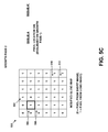
- FIG. 5A An example of a 6 ⁇ 6 blend map 500 and a corresponding 6 ⁇ 6 conflict map 502 are shown in FIG. 5A .
- Conflict map 502 indicates that five pairs of pixels in tile X and tile Y are in conflict.
- the pixel locations of the pixels in conflict are identified on blend map 500 as pixel locations 504 , 506 , 508 , 510 , and 512 .
- a two-dimensional median filter may be applied to the blend map.
- a two-dimensional min filter followed by a two-dimensional max filter may be applied to the blend map. This filtering may serve to reduce impulse noise (small holes or islands of pixels which exhibit one or more significantly different color channel values than neighboring pixels) in the image, while maintaining edges.
- the blend map For pixels for which there is a conflict, in some cases it may be beneficial to modify the blend map. For example, conflicts are usually not problematic when they occur deep in an area where the blend map indicates that all pixels should come from either one image or the other. However, conflicts located along a 0/1 edge (the blend zone) in the blend map are more likely to be noticeable and unappealing in the output image (e.g., they appear as “ghosting”). Therefore, when there is a conflict in the blend zone, the corresponding blend map values may be modified.
- the blend zone may be grown in one or more growth passes.
- two iterations over queue A may be performed.
- the blend map values of each pixel location in queue A are set to 1.
- the result of this first iteration is shown in FIG. 5B .
- FIG. 5B shows that the blend map values at pixel locations 508 and 510 have been set to 1 in modified blend map 520 .
- Growth pass 2 repeats the procedure described above for growth pass 1.
- the growth passes end when either of two possible termination conditions occur.
- the first termination condition is that queue A is empty. This indicates that alignment of the pixels was successful and that merging of the pixels may be carried out according to the blend map.
- the second condition is that a total number or percent of pixels that were set to 1 during the growth passes exceed a threshold value (e.g., 2% of all pixels in the tile, 5% of all pixels in the image, etc.). This indicates that the alignment of the images and/or tiles has failed, and that tile Y should not be merged with tile X.
- a threshold value e.g., 2% of all pixels in the tile, 5% of all pixels in the image, etc.
- pixel location 506 is set to 1.
- the modified blend map is shown in FIG. 5C . Since no neighboring pixels locations meet the criteria for being added to queue A′, queue A′ remains empty, and queue A is emptied at the end of growth pass 2. Therefore, the growth passes end after growth pass 2, because one of the termination conditions (queue A being empty) has been met.
- a max filter may be applied to the blend map.
- the radius used by the max filter may depend on the size of the image. For instance, for a 5 megapixel image, a radius of 4 pixels may be used.
- the blend map may be modified to take on 8-bit values.
- a 0 in the binary blend map becomes a 0 in the 8-bit blend map
- a 1 in the binary blend map becomes a 255 in the 8-bit blend map.
- the 8-bit blend map may be blurred using a similar radius as was used by the max filter.
- the blend map may be used to merge the base image and the alternate image into a single, linear, 16-bit image.
- One, the other, or both of the base and alternate images may have been scaled to the same virtual exposure before merging.
- a number of synthetic exposures, n may be derived from the 16-bit image. The value of n may be, for instance, between 2 and 5, inclusive.
- These synthetic exposures may be merged using an HDR local tonemapping algorithm (such as Exposure Fusion, or Local Laplacian Filters) into a single, 8-bit, locally-tonemapped image.
- an HDR local tonemapping algorithm such as Exposure Fusion, or Local Laplacian Filters
- the step of forming the 16-bit image may be skipped, and an HDR local tonemapping algorithm may be used to merge the base image and the alternate image directly.
- FIG. 6 depicts a flow chart, in accordance with an example embodiment.
- Tile X may represent a portion of the base image
- tile Y may represent a portion of the alternate image.
- X(i,j) may represent one or more pixel values of X indexed by i and j
- Y(i,j) may represent one or more pixel values of Y indexed by i and j.
- X and Y may have been aligned with one another.
- the base image may have been captured with a longer TET than the alternate image.
- an m ⁇ n blend map, B, for X and Y may be obtained.
- B(i,j) may take on a first value to refer to X(i,j), or a second value to refer to Y(i,j).
- B may be an m ⁇ n binary blend map, where the first value is 0 and the second value is 1.
- Obtaining B may involve, for 0 ⁇ i ⁇ m and 0 ⁇ j ⁇ n, setting B(i,j) to the first value where the one or more pixel values of X(i,j) are less than a blend map threshold value, or setting B(i,j) to the second value where the one or more pixel values of X(i,j) are greater than or equal to the blend map threshold value.
- the blend map threshold value may be, for instance, 255.
- an m ⁇ n conflict map, C, for X and Y may be obtained.
- C(i,j) may take on a third value where X(i,j) and Y(i,j) are within a threshold value of one another, or a fourth value where X(i,j) and Y(i,j) are not within the threshold value of one another.
- C may be an m ⁇ n binary conflict map, where the third value is 0 and the fourth value is 1.
- Obtaining C may involve, for 0 ⁇ i ⁇ m and 0 ⁇ j ⁇ n, setting C(i,j) to the third value where X(i,j) and Y(i,j) are within the threshold value of one another, or setting C(i,j) to the fourth value where X(i,j) and Y(i,j) are not within the threshold value of one another.
- X(i,j) and Y(i,j) being within the threshold value of one another may indicate that the difference between X(i,j) and Y(i,j) is less than the threshold value.
- the base image may have been captured with a TET of x and the alternate image captured with a TET of y, where C(i,j) is the third value when X(i,j) and Y(i,j)(x/y) are within the threshold value of one another, and where C(i,j) is the fourth value when X(i,j) and Y(i,j)(x/y) are not within the threshold value of one another.
- reverse tonemapping may be applied to at least one of X(i,j) and Y(i,j) prior to making the comparison between X(i,j) and Y(i,j)(x/y).
- the pixel values of X and Y may be merged to form an m ⁇ n tile Z that represents a portion of the scene.
- Merging the pixel values of X and Y to form Z may involve setting B(i,j) to the second value where B(i,j) is the first value, C(i,j) is the fourth value, and at least one adjacent neighbor to B(i,j) in B is the second value, setting Z(i,j) to X(i,j) where B(i,j) is the first value, and setting Z(i,j) to Y(i,j) where B(i,j) is the second value.
- blend map adjustments may propagate between tiles. Thus, even if alignment occurs on a per-tile basis, merging may occur across multiple tiles or on the whole image at once. For instance, the m ⁇ n tiles X and Y may be considered to be the size of the entire image.
- merging the pixel values of X and Y to form Z may involve determining an m ⁇ n blend map, B′, where B′(i,j) is set to a fifth value where B(i,j) is the first value, and wherein B′(i,j) is set to a sixth value where B(i,j) is the second value, based on B′, merging X and Y into a high dynamic range image, creating a plurality of synthetic exposures of B′, where at least two of the synthetic exposures are associated with different TETs, and forming Z based on the plurality of synthetic exposures of B′.
- Z may be a low dynamic range image.
- the fifth value may be 0 and the sixth value may be 255.
- the steps depicted in FIG. 6 may be carried out by a camera device, such as digital camera device 100 , a computing device, such as computing device 200 , and/or by two or more distinct devices. Further, the flow chart depicted in FIG. 6 may be modified according to the variations disclosed in this specification and/or the accompanying drawings.
- each step, block and/or communication may represent a processing of information and/or a transmission of information in accordance with example embodiments.
- Alternative embodiments are included within the scope of these example embodiments.
- functions described as steps, blocks, transmissions, communications, requests, responses, and/or messages may be executed out of order from that shown or discussed, including in substantially concurrent or in reverse order, depending on the functionality involved.
- more or fewer steps, blocks and/or functions may be used with any of the message flow diagrams, scenarios, and flow charts discussed herein, and these message flow diagrams, scenarios, and flow charts may be combined with one another, in part or in whole.
- a step or block that represents a processing of information may correspond to circuitry that can be configured to perform the specific logical functions of a herein-described method or technique.
- a step or block that represents a processing of information may correspond to a module, a segment, or a portion of program code (including related data).
- the program code may include one or more instructions executable by a processor for implementing specific logical functions or actions in the method or technique.
- the program code and/or related data may be stored on any type of computer-readable medium, such as a storage device, including a disk drive, a hard drive, or other storage media.
- the computer-readable medium may also include non-transitory computer-readable media such as computer-readable media that stores data for short periods of time like register memory, processor cache, and/or random access memory (RAM).
- the computer-readable media may also include non-transitory computer-readable media that stores program code and/or data for longer periods of time, such as secondary or persistent long term storage, like read only memory (ROM), optical or magnetic disks, and/or compact-disc read only memory (CD-ROM), for example.
- the computer-readable media may also be any other volatile or non-volatile storage systems.
- a computer-readable medium may be considered a computer-readable storage medium, for example, or a tangible storage device.
- a step or block that represents one or more information transmissions may correspond to information transmissions between software and/or hardware modules in the same physical device. However, other information transmissions may be between software modules and/or hardware modules in different physical devices.
Abstract
Description
| TABLE 1 | |
| Scene Type | Payload Burst Structure |
| LDR | T T T T |
| HDR | L S L L S L L S L L |
| HDR (with fallback) | L S L L S L L F F F |
Z(i,j)=X(i,j), if B(i,j)=0
Z(i,j)=Y(i,j), if B(i,j)=1
The above equations may assume that the brightnesses of tiles X and Y have been scaled to match one another. For example, if tile X was captured using a TET of 2, tile Y was captured using a TET of 7, and both have values limited to 0 through 255, inclusive, then a digital gain of 3.5× may be applied to the brightness values of pixels in tile X before doing operations to construct tile Z. As a result, tile Z would then have a “virtual TET” of 7.
Claims (20)
Priority Applications (1)
| Application Number | Priority Date | Filing Date | Title |
|---|---|---|---|
| US13/847,238 US9117134B1 (en) | 2013-03-19 | 2013-03-19 | Image merging with blending |
Applications Claiming Priority (1)
| Application Number | Priority Date | Filing Date | Title |
|---|---|---|---|
| US13/847,238 US9117134B1 (en) | 2013-03-19 | 2013-03-19 | Image merging with blending |
Publications (1)
| Publication Number | Publication Date |
|---|---|
| US9117134B1 true US9117134B1 (en) | 2015-08-25 |
Family
ID=53838499
Family Applications (1)
| Application Number | Title | Priority Date | Filing Date |
|---|---|---|---|
| US13/847,238 Active 2033-10-21 US9117134B1 (en) | 2013-03-19 | 2013-03-19 | Image merging with blending |
Country Status (1)
| Country | Link |
|---|---|
| US (1) | US9117134B1 (en) |
Cited By (23)
| Publication number | Priority date | Publication date | Assignee | Title |
|---|---|---|---|---|
| GB2538584A (en) * | 2015-03-30 | 2016-11-23 | Imagination Tech Ltd | Image filtering based on image gradients |
| US10013622B2 (en) | 2016-06-30 | 2018-07-03 | International Business Machines Corporation | Removing unwanted objects from a photograph |
| US10075655B2 (en) | 2015-06-02 | 2018-09-11 | Samsung Electronics Co., Ltd. | Tonal-zone adaptive tone mapping |
| US10726611B1 (en) * | 2016-08-24 | 2020-07-28 | Electronic Arts Inc. | Dynamic texture mapping using megatextures |
| US10733765B2 (en) | 2017-03-31 | 2020-08-04 | Electronic Arts Inc. | Blendshape compression system |
| US10792566B1 (en) | 2015-09-30 | 2020-10-06 | Electronic Arts Inc. | System for streaming content within a game application environment |
| US10863105B1 (en) * | 2017-06-27 | 2020-12-08 | Amazon Technologies, Inc. | High dynamic range imaging for event detection and inventory management |
| US10860838B1 (en) | 2018-01-16 | 2020-12-08 | Electronic Arts Inc. | Universal facial expression translation and character rendering system |
| US10878540B1 (en) | 2017-08-15 | 2020-12-29 | Electronic Arts Inc. | Contrast ratio detection and rendering system |
| US10902618B2 (en) | 2019-06-14 | 2021-01-26 | Electronic Arts Inc. | Universal body movement translation and character rendering system |
| US10911691B1 (en) * | 2019-11-19 | 2021-02-02 | Samsung Electronics Co., Ltd. | System and method for dynamic selection of reference image frame |
| WO2021046402A1 (en) | 2019-09-06 | 2021-03-11 | Google Llc | Low frame rate night vision on video camera |
| CN113112441A (en) * | 2021-04-30 | 2021-07-13 | 中北大学 | Multi-band low-resolution image synchronous fusion method based on dense network and local brightness traversal operator |
| US11107205B2 (en) * | 2019-02-18 | 2021-08-31 | Samsung Electronics Co., Ltd. | Techniques for convolutional neural network-based multi-exposure fusion of multiple image frames and for deblurring multiple image frames |
| US11113860B2 (en) | 2017-09-14 | 2021-09-07 | Electronic Arts Inc. | Particle-based inverse kinematic rendering system |
| US11144780B2 (en) * | 2019-07-30 | 2021-10-12 | Snap-On Incorporated | Adaptive image processing |
| US11217003B2 (en) | 2020-04-06 | 2022-01-04 | Electronic Arts Inc. | Enhanced pose generation based on conditional modeling of inverse kinematics |
| US11504625B2 (en) | 2020-02-14 | 2022-11-22 | Electronic Arts Inc. | Color blindness diagnostic system |
| US11562523B1 (en) | 2021-08-02 | 2023-01-24 | Electronic Arts Inc. | Enhanced animation generation based on motion matching using local bone phases |
| US11648480B2 (en) | 2020-04-06 | 2023-05-16 | Electronic Arts Inc. | Enhanced pose generation based on generative modeling |
| US11670030B2 (en) | 2021-07-01 | 2023-06-06 | Electronic Arts Inc. | Enhanced animation generation based on video with local phase |
| US11830121B1 (en) | 2021-01-26 | 2023-11-28 | Electronic Arts Inc. | Neural animation layering for synthesizing martial arts movements |
| US11887232B2 (en) | 2021-06-10 | 2024-01-30 | Electronic Arts Inc. | Enhanced system for generation of facial models and animation |
Citations (111)
| Publication number | Priority date | Publication date | Assignee | Title |
|---|---|---|---|---|
| US4644582A (en) | 1983-01-28 | 1987-02-17 | Hitachi, Ltd. | Image registration method |
| WO1998002844A1 (en) | 1996-07-17 | 1998-01-22 | Sarnoff Corporation | Method and apparatus for mosaic image construction |
| US5781308A (en) | 1996-03-04 | 1998-07-14 | Hewlett-Packard Company | High speed system for threshold matrix alignment and tiling, during creation of a binary half-tone image |
| US5828793A (en) | 1996-05-06 | 1998-10-27 | Massachusetts Institute Of Technology | Method and apparatus for producing digital images having extended dynamic ranges |
| US5926190A (en) | 1996-08-21 | 1999-07-20 | Apple Computer, Inc. | Method and system for simulating motion in a computer graphics application using image registration and view interpolation |
| US6061091A (en) | 1996-05-30 | 2000-05-09 | Agfa Gevaert N.V. | Detection of and correction for specular reflections in digital image acquisition |
| US6101285A (en) | 1998-03-23 | 2000-08-08 | Xerox Corporation | Filter for producing continuous tone images from halftone digital images data |
| US6204881B1 (en) | 1993-10-10 | 2001-03-20 | Canon Kabushiki Kaisha | Image data processing apparatus which can combine a plurality of images at different exposures into an image with a wider dynamic range |
| US20010019362A1 (en) | 2000-02-22 | 2001-09-06 | Kenji Nakamura | Digital camera and recording medium |
| US20030002750A1 (en) | 1997-09-10 | 2003-01-02 | Koichi Ejiri | System and method for displaying an image indicating a positional relation between partially overlapping images |
| US6539116B2 (en) | 1997-10-09 | 2003-03-25 | Canon Kabushiki Kaisha | Information processing apparatus and method, and computer readable memory therefor |
| US20030095192A1 (en) | 2000-10-26 | 2003-05-22 | Olympus Optical Co., Ltd. | Image-pickup apparatus |
| US6693718B1 (en) | 1998-05-29 | 2004-02-17 | Canon Kabushiki Kaisha | Image processing apparatus and method for processing a color image, and storage medium storing program code of the method |
| US20040160525A1 (en) | 2003-02-14 | 2004-08-19 | Minolta Co., Ltd. | Image processing apparatus and method |
| JP2005045804A (en) | 2003-07-18 | 2005-02-17 | Microsoft Corp | System and process for generating high dynamic range image |
| WO2004098167A3 (en) | 2003-04-29 | 2005-04-28 | Microsoft Corp | A system and process for generating high dynamic range video |
| US20050147322A1 (en) | 2003-10-01 | 2005-07-07 | Aryan Saed | Digital composition of a mosaic image |
| US20050163380A1 (en) | 2004-01-27 | 2005-07-28 | Samsung Electronics Co., Ltd. | Method and apparatus for detecting the location and luminance transition range of slant image edges |
| US6925121B1 (en) | 1997-10-01 | 2005-08-02 | Matsushita Electric Industrial Co., Ltd. | Motion vector detecting method and system and devices incorporating the same |
| US20050239104A1 (en) | 2003-11-04 | 2005-10-27 | Ferea Tracy L | Microarray controls |
| US20050243176A1 (en) | 2004-04-30 | 2005-11-03 | James Wu | Method of HDR image processing and manipulation |
| US6975755B1 (en) | 1999-11-25 | 2005-12-13 | Canon Kabushiki Kaisha | Image processing method and apparatus |
| US7098946B1 (en) | 1998-09-16 | 2006-08-29 | Olympus Optical Co., Ltd. | Image pickup apparatus |
| US20060269155A1 (en) | 2005-05-09 | 2006-11-30 | Lockheed Martin Corporation | Continuous extended range image processing |
| US20060291740A1 (en) | 2005-06-28 | 2006-12-28 | Lg Philips Lcd Co., Ltd. | Method of median filtering |
| US20070003261A1 (en) | 2005-06-30 | 2007-01-04 | Masafumi Yamasaki | Electronic blurring correction apparatus |
| US7173666B1 (en) | 2002-08-22 | 2007-02-06 | Smal Camera Technologies | System and method for displaying a non-standard aspect ratio image on a standard aspect ratio monitor |
| US20070147824A1 (en) | 2005-12-27 | 2007-06-28 | Samsung Techwin Co., Ltd. | Photographing apparatus and method |
| US7239805B2 (en) | 2005-02-01 | 2007-07-03 | Microsoft Corporation | Method and system for combining multiple exposure images having scene and camera motion |
| KR20070085867A (en) | 2004-12-07 | 2007-08-27 | 브라잇 이미징 리미티드 | Methods and apparatus for imaging of scenes having large intensity variance |
| US20080094486A1 (en) | 2006-10-20 | 2008-04-24 | Chiou-Shann Fuh | Method and system of generating high dynamic range image corresponding to specific scene |
| US20080253758A1 (en) | 2007-04-13 | 2008-10-16 | Choon Hwee Yap | Image processing method |
| US20080278633A1 (en) | 2007-05-09 | 2008-11-13 | Mikhail Tsoupko-Sitnikov | Image processing method and image processing apparatus |
| US20080298717A1 (en) | 2005-12-29 | 2008-12-04 | Mtekvision Co., Ltd. | Device of Processing Dead Pixel |
| US20090040364A1 (en) | 2005-08-08 | 2009-02-12 | Joseph Rubner | Adaptive Exposure Control |
| US20090123082A1 (en) | 2007-11-12 | 2009-05-14 | Qualcomm Incorporated | Block-based image stabilization |
| US20090185622A1 (en) | 2002-09-12 | 2009-07-23 | Goh Itoh | Method of searching for motion vector, method of generating frame interpolation image and display system |
| KR100911814B1 (en) | 2007-10-08 | 2009-08-12 | 성균관대학교산학협력단 | Stereo-image matching error removal apparatus and removal methord using the same |
| US20090207258A1 (en) | 2008-02-18 | 2009-08-20 | Samsung Techwin Co., Ltd. | Digital photographing apparatus, method of controlling the digital photographing apparatus, and recording medium having recorded thereon a program for executing the method |
| US20090222625A1 (en) | 2005-09-13 | 2009-09-03 | Mrinmoy Ghosh | Cache miss detection in a data processing apparatus |
| US20090231468A1 (en) | 2008-03-13 | 2009-09-17 | Samsung Techwin Co., Ltd. | Digital imaging apparatus enabled to control flash light intensity, method of controlling the digital imaging apparatus, and recording medium having recorded thereon program for executing the method |
| US20090231449A1 (en) | 2008-03-11 | 2009-09-17 | Zoran Corporation | Image enhancement based on multiple frames and motion estimation |
| US20090231445A1 (en) | 2008-03-17 | 2009-09-17 | Makoto Kanehiro | Imaging apparatus |
| US20090244301A1 (en) | 2008-04-01 | 2009-10-01 | Border John N | Controlling multiple-image capture |
| US20090268963A1 (en) | 2008-04-23 | 2009-10-29 | Samsung Techwin Co., Ltd. | Pre-processing method and apparatus for wide dynamic range image processing |
| US20090274387A1 (en) | 2008-05-05 | 2009-11-05 | Micron Technology, Inc. | Method of capturing high dynamic range images with objects in the scene |
| US7626614B1 (en) | 2005-02-15 | 2009-12-01 | Apple Inc. | Transfer function and high dynamic range images |
| US20090322901A1 (en) | 2008-06-27 | 2009-12-31 | Micron Technology, Inc. | Method and apparatus providing rule-based auto exposure technique preserving scene dynamic range |
| US7667764B2 (en) | 2004-06-04 | 2010-02-23 | Konica Minolta Holdings, Inc. | Image sensing apparatus |
| US20100066858A1 (en) | 2008-09-12 | 2010-03-18 | Sony Corporation | Imaging apparatus and imaging mode control method |
| US20100103194A1 (en) | 2008-10-27 | 2010-04-29 | Huawei Technologies Co., Ltd. | Method and system for fusing images |
| US20100150473A1 (en) | 2008-12-16 | 2010-06-17 | Jae-Hyun Kwon | Apparatus and method for blending multiple images |
| US20100157078A1 (en) | 2008-12-19 | 2010-06-24 | Qualcomm Incorporated | High dynamic range image combining |
| US20100166337A1 (en) | 2007-09-25 | 2010-07-01 | Fujitsu Limited | Image merge device and method |
| US20100165075A1 (en) | 2008-12-31 | 2010-07-01 | Altek Corporation | Method for automatically shooting panoramic image by digital image pickup device |
| KR20100086987A (en) | 2007-10-26 | 2010-08-02 | 옴니비전 테크놀러지즈 인코포레이티드 | High dynamic range image sensor with reduced line memory for color interpolation |
| US20100265357A1 (en) | 2009-04-17 | 2010-10-21 | Sony Corporation | Generation of simulated long exposure images in response to multiple short exposures |
| US20100277631A1 (en) | 2009-04-30 | 2010-11-04 | Toshinobu Sugiyama | Solid-state imaging device, driving method thereof, and imaging apparatus |
| US7840093B2 (en) | 2004-06-30 | 2010-11-23 | Accuray, Inc. | Image enhancement method and system for fiducial-less tracking of treatment targets |
| US20100321539A1 (en) | 2009-06-22 | 2010-12-23 | Canon Kabushiki Kaisha | Image processing apparatus and image processing method |
| US20100328491A1 (en) | 2006-08-30 | 2010-12-30 | Ilia Ovsiannikov | Method, apparatus and system for dynamic range estimation of imaged scenes |
| US20100328490A1 (en) | 2009-06-26 | 2010-12-30 | Seiko Epson Corporation | Imaging control apparatus, imaging apparatus and imaging control method |
| US20110047155A1 (en) | 2008-04-17 | 2011-02-24 | Samsung Electronics Co., Ltd. | Multimedia encoding method and device based on multimedia content characteristics, and a multimedia decoding method and device based on multimedia |
| US7903168B2 (en) | 2006-04-06 | 2011-03-08 | Eastman Kodak Company | Camera and method with additional evaluation image capture based on scene brightness changes |
| US20110069200A1 (en) | 2009-09-22 | 2011-03-24 | Samsung Electronics Co., Ltd. | High dynamic range image generating apparatus and method |
| US7924321B2 (en) | 1999-06-04 | 2011-04-12 | The Trustees Of Columbia University In The City Of New York | Apparatus and method for high dynamic range imaging using spatially varying exposures |
| US20110085697A1 (en) | 2009-10-09 | 2011-04-14 | Ric Clippard | Automatic method to generate product attributes based solely on product images |
| US7940325B2 (en) | 2007-08-23 | 2011-05-10 | Samsung Electronics Co., Ltd | Apparatus and method of capturing images having optimized quality under night scene conditions |
| US20110149111A1 (en) | 2009-12-22 | 2011-06-23 | Prentice Wayne E | Creating an image using still and preview |
| WO2011093994A1 (en) | 2010-01-27 | 2011-08-04 | Thomson Licensing | High dynamic range (hdr) image synthesis with user input |
| US20110200265A1 (en) | 2008-05-19 | 2011-08-18 | Thierry Prigent | Method of recording images and data for retrieving these images |
| WO2011102850A1 (en) | 2010-02-22 | 2011-08-25 | Zoran Corporation | Method and apparatus for low-light imaging enhancement |
| US20110222793A1 (en) | 2010-03-09 | 2011-09-15 | Sony Corporation | Image processing apparatus, image processing method, and program |
| US8023004B2 (en) | 2007-09-28 | 2011-09-20 | Sony Corporation | Imaging apparatus, imaging method, and program for selectively controlling gain in a normal imaging mode and a combined imaging mode |
| US20110228993A1 (en) | 2007-08-31 | 2011-09-22 | Historx, Inc. | Automatic exposure time selection for imaging tissue |
| US20110254976A1 (en) | 2009-04-23 | 2011-10-20 | Haim Garten | Multiple exposure high dynamic range image capture |
| US8059891B2 (en) | 2007-12-30 | 2011-11-15 | Intel Corporation | Markov stationary color descriptor |
| US20110279706A1 (en) | 2010-05-12 | 2011-11-17 | Li-Cor, Inc. | Wide dynamic range imaging |
| US20120002899A1 (en) | 2010-07-05 | 2012-01-05 | Orr Iv James Edmund | Aligning Images |
| US8094211B2 (en) | 2008-06-09 | 2012-01-10 | Samsung Electronics Co., Ltd. | Method and apparatus for obtaining image using entropy |
| JP2012029029A (en) | 2010-07-23 | 2012-02-09 | Seiko Epson Corp | Image processing device, image processing method and imaging device |
| US20120044381A1 (en) | 2010-08-23 | 2012-02-23 | Red.Com, Inc. | High dynamic range video |
| US20120050557A1 (en) | 2010-09-01 | 2012-03-01 | Qualcomm Incorporated | High dynamic range image sensor |
| WO2012039669A1 (en) | 2010-09-20 | 2012-03-29 | Scalado Ab | Method for forming images |
| US20120105681A1 (en) | 2010-11-03 | 2012-05-03 | Morales Efrain O | Method for producing high dynamic range images |
| US20120127348A1 (en) | 2010-11-22 | 2012-05-24 | Altek Corporation | Image capturing device and image synthesis method thereof |
| US8200020B1 (en) | 2011-11-28 | 2012-06-12 | Google Inc. | Robust image alignment using block sums |
| US8208048B2 (en) | 2009-02-05 | 2012-06-26 | National Chung Cheng University | Method for high dynamic range imaging |
| WO2012098842A1 (en) | 2011-01-20 | 2012-07-26 | パナソニック株式会社 | Feature extraction unit, feature extraction method, feature extraction program, and image processing device |
| US20120189197A1 (en) | 2008-04-25 | 2012-07-26 | Jianguo Li | Device, system, and method for indexing digital image frames |
| US8237813B2 (en) | 2009-04-23 | 2012-08-07 | Csr Technology Inc. | Multiple exposure high dynamic range image capture |
| US20120201426A1 (en) | 2011-02-04 | 2012-08-09 | David Wayne Jasinski | Estimating subject motion for capture setting determination |
| US20120201456A1 (en) | 2009-10-08 | 2012-08-09 | International Business Machines Corporation | Transforming a digital image from a low dynamic range (ldr) image to a high dynamic range (hdr) image |
| US20120201450A1 (en) | 2011-02-04 | 2012-08-09 | Andrew Bryant | Hue-based color matching |
| WO2012110894A1 (en) | 2011-02-18 | 2012-08-23 | DigitalOptics Corporation Europe Limited | Dynamic range extension by combining differently exposed hand-held device-acquired images |
| US20120219235A1 (en) | 2011-02-28 | 2012-08-30 | Johannes Solhusvik | Blooming filter for multiple exposure high dynamic range image sensors |
| US20120249828A1 (en) | 2011-03-28 | 2012-10-04 | Aptina Imaging Corporation | Apparataus and method of automatic color shading removal in cmos image sensors |
| US20120308126A1 (en) | 2011-05-31 | 2012-12-06 | Korea Electronics Technology Institute | Corresponding image processing method for compensating colour |
| US20120314100A1 (en) | 2011-06-09 | 2012-12-13 | Apple Inc. | Image sensor having hdr capture capability |
| US20130033616A1 (en) | 2011-08-04 | 2013-02-07 | Sony Corporation | Imaging device, image processing method and program |
| US8406560B2 (en) | 2010-01-15 | 2013-03-26 | Samsung Electronics Co., Ltd. | Apparatus and method for generating high sensitivity images in dark environment |
| US20130083216A1 (en) | 2011-10-04 | 2013-04-04 | Samsung Electronics Co. Ltd. | Apparatus and method for automatic white balance with supplementary sensors |
| US20130100314A1 (en) | 2011-10-06 | 2013-04-25 | Aptina Imaging Corporation | Imaging systems and methods for generating motion-compensated high-dynamic-range images |
| US20130121569A1 (en) * | 2009-09-14 | 2013-05-16 | Vikas Yadav | Methods and Apparatus for Blending Images |
| US8446481B1 (en) | 2012-09-11 | 2013-05-21 | Google Inc. | Interleaved capture for high dynamic range image acquisition and synthesis |
| US20130329092A1 (en) | 2012-06-06 | 2013-12-12 | Apple Inc. | Intelligent Auto-Exposure Bracketing |
| US20140042233A1 (en) | 2011-02-18 | 2014-02-13 | Artarch & Door Works Inc. | Design code pattern comprising information deciphered by digital device and operating system for same |
| US20140219578A1 (en) | 2013-02-07 | 2014-08-07 | Altek Semiconductor Corp. | Image processing method |
| US8866928B2 (en) | 2012-12-18 | 2014-10-21 | Google Inc. | Determining exposure times using split paxels |
| US8866927B2 (en) | 2012-12-13 | 2014-10-21 | Google Inc. | Determining an image capture payload burst structure based on a metering image capture sweep |
| US8885976B1 (en) * | 2013-06-20 | 2014-11-11 | Cyberlink Corp. | Systems and methods for performing image fusion |
-
2013
- 2013-03-19 US US13/847,238 patent/US9117134B1/en active Active
Patent Citations (120)
| Publication number | Priority date | Publication date | Assignee | Title |
|---|---|---|---|---|
| US4644582A (en) | 1983-01-28 | 1987-02-17 | Hitachi, Ltd. | Image registration method |
| US6204881B1 (en) | 1993-10-10 | 2001-03-20 | Canon Kabushiki Kaisha | Image data processing apparatus which can combine a plurality of images at different exposures into an image with a wider dynamic range |
| US5781308A (en) | 1996-03-04 | 1998-07-14 | Hewlett-Packard Company | High speed system for threshold matrix alignment and tiling, during creation of a binary half-tone image |
| US5828793A (en) | 1996-05-06 | 1998-10-27 | Massachusetts Institute Of Technology | Method and apparatus for producing digital images having extended dynamic ranges |
| US6061091A (en) | 1996-05-30 | 2000-05-09 | Agfa Gevaert N.V. | Detection of and correction for specular reflections in digital image acquisition |
| WO1998002844A1 (en) | 1996-07-17 | 1998-01-22 | Sarnoff Corporation | Method and apparatus for mosaic image construction |
| US6075905A (en) | 1996-07-17 | 2000-06-13 | Sarnoff Corporation | Method and apparatus for mosaic image construction |
| US5926190A (en) | 1996-08-21 | 1999-07-20 | Apple Computer, Inc. | Method and system for simulating motion in a computer graphics application using image registration and view interpolation |
| US20030002750A1 (en) | 1997-09-10 | 2003-01-02 | Koichi Ejiri | System and method for displaying an image indicating a positional relation between partially overlapping images |
| US6925121B1 (en) | 1997-10-01 | 2005-08-02 | Matsushita Electric Industrial Co., Ltd. | Motion vector detecting method and system and devices incorporating the same |
| US6539116B2 (en) | 1997-10-09 | 2003-03-25 | Canon Kabushiki Kaisha | Information processing apparatus and method, and computer readable memory therefor |
| US6101285A (en) | 1998-03-23 | 2000-08-08 | Xerox Corporation | Filter for producing continuous tone images from halftone digital images data |
| US6693718B1 (en) | 1998-05-29 | 2004-02-17 | Canon Kabushiki Kaisha | Image processing apparatus and method for processing a color image, and storage medium storing program code of the method |
| US7098946B1 (en) | 1998-09-16 | 2006-08-29 | Olympus Optical Co., Ltd. | Image pickup apparatus |
| US7924321B2 (en) | 1999-06-04 | 2011-04-12 | The Trustees Of Columbia University In The City Of New York | Apparatus and method for high dynamic range imaging using spatially varying exposures |
| US6975755B1 (en) | 1999-11-25 | 2005-12-13 | Canon Kabushiki Kaisha | Image processing method and apparatus |
| US20010019362A1 (en) | 2000-02-22 | 2001-09-06 | Kenji Nakamura | Digital camera and recording medium |
| US20030095192A1 (en) | 2000-10-26 | 2003-05-22 | Olympus Optical Co., Ltd. | Image-pickup apparatus |
| US7173666B1 (en) | 2002-08-22 | 2007-02-06 | Smal Camera Technologies | System and method for displaying a non-standard aspect ratio image on a standard aspect ratio monitor |
| US20090185622A1 (en) | 2002-09-12 | 2009-07-23 | Goh Itoh | Method of searching for motion vector, method of generating frame interpolation image and display system |
| US20040160525A1 (en) | 2003-02-14 | 2004-08-19 | Minolta Co., Ltd. | Image processing apparatus and method |
| WO2004098167A3 (en) | 2003-04-29 | 2005-04-28 | Microsoft Corp | A system and process for generating high dynamic range video |
| JP2005045804A (en) | 2003-07-18 | 2005-02-17 | Microsoft Corp | System and process for generating high dynamic range image |
| US20050147322A1 (en) | 2003-10-01 | 2005-07-07 | Aryan Saed | Digital composition of a mosaic image |
| US20050239104A1 (en) | 2003-11-04 | 2005-10-27 | Ferea Tracy L | Microarray controls |
| US20050163380A1 (en) | 2004-01-27 | 2005-07-28 | Samsung Electronics Co., Ltd. | Method and apparatus for detecting the location and luminance transition range of slant image edges |
| US20050243176A1 (en) | 2004-04-30 | 2005-11-03 | James Wu | Method of HDR image processing and manipulation |
| US7667764B2 (en) | 2004-06-04 | 2010-02-23 | Konica Minolta Holdings, Inc. | Image sensing apparatus |
| US7840093B2 (en) | 2004-06-30 | 2010-11-23 | Accuray, Inc. | Image enhancement method and system for fiducial-less tracking of treatment targets |
| KR20070085867A (en) | 2004-12-07 | 2007-08-27 | 브라잇 이미징 리미티드 | Methods and apparatus for imaging of scenes having large intensity variance |
| US7239805B2 (en) | 2005-02-01 | 2007-07-03 | Microsoft Corporation | Method and system for combining multiple exposure images having scene and camera motion |
| US7626614B1 (en) | 2005-02-15 | 2009-12-01 | Apple Inc. | Transfer function and high dynamic range images |
| US20060269155A1 (en) | 2005-05-09 | 2006-11-30 | Lockheed Martin Corporation | Continuous extended range image processing |
| US20060291740A1 (en) | 2005-06-28 | 2006-12-28 | Lg Philips Lcd Co., Ltd. | Method of median filtering |
| US20070003261A1 (en) | 2005-06-30 | 2007-01-04 | Masafumi Yamasaki | Electronic blurring correction apparatus |
| US20090040364A1 (en) | 2005-08-08 | 2009-02-12 | Joseph Rubner | Adaptive Exposure Control |
| US20090222625A1 (en) | 2005-09-13 | 2009-09-03 | Mrinmoy Ghosh | Cache miss detection in a data processing apparatus |
| US20070147824A1 (en) | 2005-12-27 | 2007-06-28 | Samsung Techwin Co., Ltd. | Photographing apparatus and method |
| US20080298717A1 (en) | 2005-12-29 | 2008-12-04 | Mtekvision Co., Ltd. | Device of Processing Dead Pixel |
| US7903168B2 (en) | 2006-04-06 | 2011-03-08 | Eastman Kodak Company | Camera and method with additional evaluation image capture based on scene brightness changes |
| US20100328491A1 (en) | 2006-08-30 | 2010-12-30 | Ilia Ovsiannikov | Method, apparatus and system for dynamic range estimation of imaged scenes |
| US7944485B2 (en) | 2006-08-30 | 2011-05-17 | Micron Technology, Inc. | Method, apparatus and system for dynamic range estimation of imaged scenes |
| US8072507B2 (en) | 2006-10-20 | 2011-12-06 | Primax Electronics Ltd. | Method and system of generating high dynamic range image corresponding to specific scene |
| US20080094486A1 (en) | 2006-10-20 | 2008-04-24 | Chiou-Shann Fuh | Method and system of generating high dynamic range image corresponding to specific scene |
| US20080253758A1 (en) | 2007-04-13 | 2008-10-16 | Choon Hwee Yap | Image processing method |
| US20080278633A1 (en) | 2007-05-09 | 2008-11-13 | Mikhail Tsoupko-Sitnikov | Image processing method and image processing apparatus |
| US7940325B2 (en) | 2007-08-23 | 2011-05-10 | Samsung Electronics Co., Ltd | Apparatus and method of capturing images having optimized quality under night scene conditions |
| US20110228993A1 (en) | 2007-08-31 | 2011-09-22 | Historx, Inc. | Automatic exposure time selection for imaging tissue |
| US20100166337A1 (en) | 2007-09-25 | 2010-07-01 | Fujitsu Limited | Image merge device and method |
| US8023004B2 (en) | 2007-09-28 | 2011-09-20 | Sony Corporation | Imaging apparatus, imaging method, and program for selectively controlling gain in a normal imaging mode and a combined imaging mode |
| KR100911814B1 (en) | 2007-10-08 | 2009-08-12 | 성균관대학교산학협력단 | Stereo-image matching error removal apparatus and removal methord using the same |
| KR20100086987A (en) | 2007-10-26 | 2010-08-02 | 옴니비전 테크놀러지즈 인코포레이티드 | High dynamic range image sensor with reduced line memory for color interpolation |
| US20090123082A1 (en) | 2007-11-12 | 2009-05-14 | Qualcomm Incorporated | Block-based image stabilization |
| US8059891B2 (en) | 2007-12-30 | 2011-11-15 | Intel Corporation | Markov stationary color descriptor |
| US20090207258A1 (en) | 2008-02-18 | 2009-08-20 | Samsung Techwin Co., Ltd. | Digital photographing apparatus, method of controlling the digital photographing apparatus, and recording medium having recorded thereon a program for executing the method |
| US20090231449A1 (en) | 2008-03-11 | 2009-09-17 | Zoran Corporation | Image enhancement based on multiple frames and motion estimation |
| US20090231468A1 (en) | 2008-03-13 | 2009-09-17 | Samsung Techwin Co., Ltd. | Digital imaging apparatus enabled to control flash light intensity, method of controlling the digital imaging apparatus, and recording medium having recorded thereon program for executing the method |
| US20090231445A1 (en) | 2008-03-17 | 2009-09-17 | Makoto Kanehiro | Imaging apparatus |
| US20090244301A1 (en) | 2008-04-01 | 2009-10-01 | Border John N | Controlling multiple-image capture |
| US20110047155A1 (en) | 2008-04-17 | 2011-02-24 | Samsung Electronics Co., Ltd. | Multimedia encoding method and device based on multimedia content characteristics, and a multimedia decoding method and device based on multimedia |
| US20090268963A1 (en) | 2008-04-23 | 2009-10-29 | Samsung Techwin Co., Ltd. | Pre-processing method and apparatus for wide dynamic range image processing |
| US20120189197A1 (en) | 2008-04-25 | 2012-07-26 | Jianguo Li | Device, system, and method for indexing digital image frames |
| US20090274387A1 (en) | 2008-05-05 | 2009-11-05 | Micron Technology, Inc. | Method of capturing high dynamic range images with objects in the scene |
| US20110200265A1 (en) | 2008-05-19 | 2011-08-18 | Thierry Prigent | Method of recording images and data for retrieving these images |
| US8094211B2 (en) | 2008-06-09 | 2012-01-10 | Samsung Electronics Co., Ltd. | Method and apparatus for obtaining image using entropy |
| US20090322901A1 (en) | 2008-06-27 | 2009-12-31 | Micron Technology, Inc. | Method and apparatus providing rule-based auto exposure technique preserving scene dynamic range |
| US20100066858A1 (en) | 2008-09-12 | 2010-03-18 | Sony Corporation | Imaging apparatus and imaging mode control method |
| US20100103194A1 (en) | 2008-10-27 | 2010-04-29 | Huawei Technologies Co., Ltd. | Method and system for fusing images |
| US20100150473A1 (en) | 2008-12-16 | 2010-06-17 | Jae-Hyun Kwon | Apparatus and method for blending multiple images |
| US20100157078A1 (en) | 2008-12-19 | 2010-06-24 | Qualcomm Incorporated | High dynamic range image combining |
| US20100165075A1 (en) | 2008-12-31 | 2010-07-01 | Altek Corporation | Method for automatically shooting panoramic image by digital image pickup device |
| US8208048B2 (en) | 2009-02-05 | 2012-06-26 | National Chung Cheng University | Method for high dynamic range imaging |
| US20100265357A1 (en) | 2009-04-17 | 2010-10-21 | Sony Corporation | Generation of simulated long exposure images in response to multiple short exposures |
| US20110254976A1 (en) | 2009-04-23 | 2011-10-20 | Haim Garten | Multiple exposure high dynamic range image capture |
| US8237813B2 (en) | 2009-04-23 | 2012-08-07 | Csr Technology Inc. | Multiple exposure high dynamic range image capture |
| US20100277631A1 (en) | 2009-04-30 | 2010-11-04 | Toshinobu Sugiyama | Solid-state imaging device, driving method thereof, and imaging apparatus |
| US20100321539A1 (en) | 2009-06-22 | 2010-12-23 | Canon Kabushiki Kaisha | Image processing apparatus and image processing method |
| US8576295B2 (en) | 2009-06-22 | 2013-11-05 | Canon Kabushiki Kaisha | Image processing apparatus and image processing method |
| US20100328490A1 (en) | 2009-06-26 | 2010-12-30 | Seiko Epson Corporation | Imaging control apparatus, imaging apparatus and imaging control method |
| US20130121569A1 (en) * | 2009-09-14 | 2013-05-16 | Vikas Yadav | Methods and Apparatus for Blending Images |
| US20110069200A1 (en) | 2009-09-22 | 2011-03-24 | Samsung Electronics Co., Ltd. | High dynamic range image generating apparatus and method |
| US20120201456A1 (en) | 2009-10-08 | 2012-08-09 | International Business Machines Corporation | Transforming a digital image from a low dynamic range (ldr) image to a high dynamic range (hdr) image |
| US20110085697A1 (en) | 2009-10-09 | 2011-04-14 | Ric Clippard | Automatic method to generate product attributes based solely on product images |
| US20110149111A1 (en) | 2009-12-22 | 2011-06-23 | Prentice Wayne E | Creating an image using still and preview |
| US8406560B2 (en) | 2010-01-15 | 2013-03-26 | Samsung Electronics Co., Ltd. | Apparatus and method for generating high sensitivity images in dark environment |
| WO2011093994A1 (en) | 2010-01-27 | 2011-08-04 | Thomson Licensing | High dynamic range (hdr) image synthesis with user input |
| WO2011102850A1 (en) | 2010-02-22 | 2011-08-25 | Zoran Corporation | Method and apparatus for low-light imaging enhancement |
| US20110222793A1 (en) | 2010-03-09 | 2011-09-15 | Sony Corporation | Image processing apparatus, image processing method, and program |
| US20110279706A1 (en) | 2010-05-12 | 2011-11-17 | Li-Cor, Inc. | Wide dynamic range imaging |
| US20120002898A1 (en) | 2010-07-05 | 2012-01-05 | Guy Cote | Operating a Device to Capture High Dynamic Range Images |
| US20120002082A1 (en) | 2010-07-05 | 2012-01-05 | Johnson Garrett M | Capturing and Rendering High Dynamic Range Images |
| US20120002899A1 (en) | 2010-07-05 | 2012-01-05 | Orr Iv James Edmund | Aligning Images |
| JP2012029029A (en) | 2010-07-23 | 2012-02-09 | Seiko Epson Corp | Image processing device, image processing method and imaging device |
| US20120044381A1 (en) | 2010-08-23 | 2012-02-23 | Red.Com, Inc. | High dynamic range video |
| WO2012027290A1 (en) | 2010-08-23 | 2012-03-01 | Red. Com, Inc. | High dynamic range video |
| US20120050557A1 (en) | 2010-09-01 | 2012-03-01 | Qualcomm Incorporated | High dynamic range image sensor |
| WO2012039669A1 (en) | 2010-09-20 | 2012-03-29 | Scalado Ab | Method for forming images |
| WO2012061261A1 (en) | 2010-11-03 | 2012-05-10 | Eastman Kodak Company | Method for producing high dynamic range images |
| US20120105681A1 (en) | 2010-11-03 | 2012-05-03 | Morales Efrain O | Method for producing high dynamic range images |
| US20120127348A1 (en) | 2010-11-22 | 2012-05-24 | Altek Corporation | Image capturing device and image synthesis method thereof |
| WO2012098842A1 (en) | 2011-01-20 | 2012-07-26 | パナソニック株式会社 | Feature extraction unit, feature extraction method, feature extraction program, and image processing device |
| US20120201450A1 (en) | 2011-02-04 | 2012-08-09 | Andrew Bryant | Hue-based color matching |
| US20120201426A1 (en) | 2011-02-04 | 2012-08-09 | David Wayne Jasinski | Estimating subject motion for capture setting determination |
| US20140042233A1 (en) | 2011-02-18 | 2014-02-13 | Artarch & Door Works Inc. | Design code pattern comprising information deciphered by digital device and operating system for same |
| WO2012110894A1 (en) | 2011-02-18 | 2012-08-23 | DigitalOptics Corporation Europe Limited | Dynamic range extension by combining differently exposed hand-held device-acquired images |
| US20120219235A1 (en) | 2011-02-28 | 2012-08-30 | Johannes Solhusvik | Blooming filter for multiple exposure high dynamic range image sensors |
| US20120249828A1 (en) | 2011-03-28 | 2012-10-04 | Aptina Imaging Corporation | Apparataus and method of automatic color shading removal in cmos image sensors |
| US20120308126A1 (en) | 2011-05-31 | 2012-12-06 | Korea Electronics Technology Institute | Corresponding image processing method for compensating colour |
| US20120314100A1 (en) | 2011-06-09 | 2012-12-13 | Apple Inc. | Image sensor having hdr capture capability |
| US20130033616A1 (en) | 2011-08-04 | 2013-02-07 | Sony Corporation | Imaging device, image processing method and program |
| US20130083216A1 (en) | 2011-10-04 | 2013-04-04 | Samsung Electronics Co. Ltd. | Apparatus and method for automatic white balance with supplementary sensors |
| US20130100314A1 (en) | 2011-10-06 | 2013-04-25 | Aptina Imaging Corporation | Imaging systems and methods for generating motion-compensated high-dynamic-range images |
| US8411962B1 (en) | 2011-11-28 | 2013-04-02 | Google Inc. | Robust image alignment using block sums |
| US8200020B1 (en) | 2011-11-28 | 2012-06-12 | Google Inc. | Robust image alignment using block sums |
| US20130329092A1 (en) | 2012-06-06 | 2013-12-12 | Apple Inc. | Intelligent Auto-Exposure Bracketing |
| US8446481B1 (en) | 2012-09-11 | 2013-05-21 | Google Inc. | Interleaved capture for high dynamic range image acquisition and synthesis |
| US8866927B2 (en) | 2012-12-13 | 2014-10-21 | Google Inc. | Determining an image capture payload burst structure based on a metering image capture sweep |
| US8866928B2 (en) | 2012-12-18 | 2014-10-21 | Google Inc. | Determining exposure times using split paxels |
| US20140219578A1 (en) | 2013-02-07 | 2014-08-07 | Altek Semiconductor Corp. | Image processing method |
| US8885976B1 (en) * | 2013-06-20 | 2014-11-11 | Cyberlink Corp. | Systems and methods for performing image fusion |
Non-Patent Citations (60)
| Title |
|---|
| "Exposure (photography)," Wikipedia, the free encyclopedia, Jun. 21, 2012, pp. 1-8 (http://en.wikipedia.org/wiki/Autoexposure#Automatic-exposure). |
| "High dynamic range imaging," Wikipedia, the free encyclopedia, Jun. 21, 2012, pp. 1-11 (http://en.wikipedia.org/wiki/High-dynamic-range-imaging). |
| "JPEG," Wikipedia, the free encyclopedia, Jul. 31, 2012, pp. 1-16 (http://en.wikipedia.org/wiki/JPEG). |
| "Metering mode," Wikipedia, the free encyclopedia, Jun. 25, 2012, pp. 1-3 (http://en.wikipedia.org/wiki/Metering-mode). |
| "Tone mapping," Wikipedia, the free encyclopedia, Jun. 21, 2012, pp. 1-10 (http://en.wikipedia.org/wiki/Tone-mapping). |
| "YCbCr," Wikipedia, the free encyclopedia, Jul. 31, 2012, pp. 1-5 (http://en.wikipedia.org/wiki/YCbCr). |
| Bauer et al., "Comparing Several Implementations of Two Recently Published Feature Detectors," In Proc. of the International Conference on Intelligent and Autonomous Systems, IAV, Toulouse, France (2007). |
| Bay et al., "SURF: Speeded Up Robust Features," 9th European Conference on Computer Vision, 2008, pp. 346-359, vol. 110, No. 3. |
| Brown, M. & Lowe, D., "Invariant Features from Interest Point Groups," Computer, (2002) p. 253-262, Available at: http://citeseerx.ist.psu.edu/viewdoc/download?doi=10.1.1.73.5616&rep=rep1&type=pdf. |
| Cyganek, Bogusaw, "Comparison of nonparametric transformations and bit vector matching for stereo correlation." Combinatorial Image Analysis, 2005, pp. 534-547. |
| Duan et al., "Tone-mapping High Dynamic Range Images by Novel Histogram Adjustment," Pattern Recognition, 2010, 39 pages, vol. 43, No. 5. |
| Fife, Wade S. et al., "Improved Census Transforms for Resource-Optimized Stereo Vision," IEEE Transactions on Circuits and Systems for Video Technology, Jan. 2013, vol. 23, No. 1, pp. 60-73. |
| Final Office Action for U.S. Appl. No. 13/863,981 mailed Dec. 24, 2014, 21 pages. |
| Final Office Action, U.S. Appl. No. 13/863,981 mailed Apr. 8, 2014, 26 pages. |
| Gelfand, Natasha, et al. "Multi-exposure imaging on mobile devices." In Proceedings of the international conference on Multimedia, ACM, 2010, pp. 823-826. |
| Hansen, Christian et al., "Chapter 1: The Image Deblurring Problem," Deblurring Images: Matrices, Spectra, and Filtering, SIAM, Philadelphia, 2006, pp. 1-12. |
| International Search Report and Written Opinion for PCT/US2014/011498 mailed Apr. 22, 2014, 11 pages. |
| International Searching Authority, International Search Report and Written Opinion for International Application No. PCT/US2014/038963 mailed Sep. 17, 2014, 12 pages. |
| International Searching Authority, International Search Report and Written Opinion for PCT/US2013/071459 mailed Mar. 13, 2014, 9 pages. |
| International Searching Authority, International Search Report and Written Opinion for PCT/US2013/071618 mailed Mar. 3, 2014, 9 pages. |
| International Searching Authority, International Search Report and Written Opinion for PCT/US2013/071663 mailed Mar. 13, 2014, 9 pages. |
| International Searching Authority, International Search Report and Written Opinion for PCT/US2013/072569 mailed Mar. 6, 2014, 9 pages. |
| International Searching Authority, International Search Report and Written Opinion for PCT/US2013/072638 mailed Mar. 11, 2014, 10 pages. |
| International Searching Authority, International Search Report and Written Opinion for PCT/US2013/72564 mailed Mar. 11, 2014, 13 pages. |
| Jin et al., "Face Detection Using Improved LBP Under Bayesian Framework," Proceedings of the Third International Conference on Image and Graphics (ICIG'04), 2004, pp. 1-4. |
| Karpenko et al., "Digital Video Stabilization and Rolling Shutter Correction using Gyroscopes," Stanford Tech Report CTSR Mar. 2011, http://graphics.stanford.edu/papers/stabilization/karpenko-gyro.pdf (Sep. 2011). |
| Lowe, D.G., "Object Recognition from Local Scale-Invariant Features," Proc. of the International Conference on Computer Vision, Sep. 20-22, 1999, pp. 1150-1157, vol. 2. |
| Mandava et al., "Speckle Noise Reduction Using Local Binary Pattern," 2nd International Conference on Communication, Computing & Security (ICCCS-2012), Procedia Technology, 2012, pp. 574-581, vol. 6. |
| Nayar et al., "Adaptive Dynamic Range Imaging: Optical Control of Pixel Exposures Over Space and Time," Proceedings of the Ninth IEEE International Conference on Computer Vision (ICCV'03), 2003, pp. 1-8. |
| Notice of Allowance for U.S. Appl. No. 13/305,389 mailed Feb. 22, 2012, 9 pages. |
| Notice of Allowance for U.S. Appl. No. 13/458,334 mailed Oct. 11, 2012, 34 pages. |
| Notice of Allowance for U.S. Appl. No. 13/610,288 mailed Feb. 28, 2013, 31 pages. |
| Notice of Allowance for U.S. Appl. No. 13/713,720 mailed Jul. 18, 2014, 13 pages. |
| Notice of Allowance for U.S. Appl. No. 13/718,533 mailed Jul. 18, 2014, 9 pages. |
| Notice of Allowance for U.S. Appl. No. 13/743,565 mailed Dec. 2, 2014, 15 pages. |
| Notice of Allowance for U.S. Appl. No. 14/455,444 mailed Oct. 2, 2014, 9 pages. |
| Office Action for U.S. Appl. No. 13/713,734 mailed Dec. 24, 2014, 12 pages. |
| Office Action for U.S. Appl. No. 13/718,533 mailed Apr. 22, 2014, 48 pages. |
| Office Action for U.S. Appl. No. 13/722,519 mailed Feb. 19, 2015, 11 pages. |
| Office Action for U.S. Appl. No. 13/722,519 mailed Sep. 4, 2014, 10 pages. |
| Office Action for U.S. Appl. No. 13/743,565 mailed Sep. 4, 2014, 20 pages. |
| Office Action for U.S. Appl. No. 13/759,749 mailed Sep. 24, 2014, 38 pages. |
| Office Action for U.S. Appl. No. 13/849,824 mailed Nov. 5, 2014, 14 pages. |
| Office Action for U.S. Appl. No. 13/863,981 mailed Jun. 24, 2014, 23 pages. |
| Office Action for U.S. Appl. No. 13/863,981 mailed Oct. 7, 2013, 45 pages. |
| Office Action for U.S. Appl. No. 13/902,254 mailed Dec. 2, 2014, 9 pages. |
| Office Action for U.S. Appl. No. 13/902,267 mailed Dec. 12, 2014, 12 pages. |
| Office Action for U.S. Appl. No. 14/488,891 mailed Feb. 13, 2015, 6 pages. |
| Office Action, U.S. Appl. No. 13/713,720, mailed Apr. 8, 2014, 46 pages. |
| Özuysal et al., "Fast Keypoint Recognition in Ten Lines of Code," Computer Vision and Pattern Recognition, IEEE Computer Society Conference on in Computer Vision and Pattern Recognition, 2007. CVPR '07. IEEE Conference on, vol. 0 (2007), pp. 1-8. doi:10.1109/CVPR.2007.383123 Key: citeulike:2943111. |
| Seemann, Torsten et al., "Structure preserving noise filtering of images using explicit local segmentation." Fourteenth International Conference on Pattern Recognition, IEEE, 1998, vol. 2, pp. 1610-1612. |
| SIFT, accessed on Oct. 21, 2011, from Wikipedia, http://en.wikipedia.org/w/index.php?title=Special: Book&bookcmd=download&collection-id=1bf75abdad524091&writer=rl&return-to=Scale-invariant+feature+transform. |
| Sinha et al., "Feature Tracking and Matching in Video Using Programmable Graphics Hardware," Machine Vision and Applications, DOI 10.1007/s00138-007-0105-z, Nov. 2007. |
| SURF, accessed on Oct. 24, 2011, from Wikipedia, http://en.wikipedia.org/wiki/SURF. |
| SynthCam iPhone, https://sites.google.com/site/marclevoy/Tutorial accessed Oct. 24, 2011. |
| Ta, Duy-Nguyen et al., "SURFTrac: Efficient Tracking and Continuous Object Recognition using Local Feature Descriptors," IEEE Computer Society Conference on Computer Vision and Pattern Recognition, 2009, pp. 2937-2944. |
| Wagner et al., "Pose Tracking from Natural Features on Mobile Phones," Proceeding ISMAR '08 Proceedings of the 7th IEEE/ACM International Symposium on Mixed and Augmented Reality IEEE Computer Society Washington, DC, USA, Sep. 15-18, 2008, pp. 125-134. |
| Wagner et al., "Real-time detection and tracking for augmented reality on mobile phones," IEEE Trans Vis Comput Graph, May-Jun. 2010, pp. 355-368, vol. 16, No. 3. |
| Winder, S.A.J. and Brown, M., "Learning Local Image Descriptors," Computer Vision and Pattern Recognition, 2007. CVPR '07. IEEE Conference on in Computer Vision and Pattern Recognition, 2007. CVPR '07. IEEE Conference on (Jun. 2007), pp. 1-8. doi:10.1109/CVPR.2007.382971 Key: citeulike:1663569. |
| Zabih et al., "Non-parametric Local Transforms for Computing Visual Correspondence," In Proceedings of European Conference on Computer Vision, Stockholm, Sweden, May 1994, pp. 151-158. |
Cited By (35)
| Publication number | Priority date | Publication date | Assignee | Title |
|---|---|---|---|---|
| GB2538584A (en) * | 2015-03-30 | 2016-11-23 | Imagination Tech Ltd | Image filtering based on image gradients |
| US9842386B2 (en) | 2015-03-30 | 2017-12-12 | Imagination Technologies Limited | Image filtering based on image gradients |
| GB2538584B (en) * | 2015-03-30 | 2018-03-07 | Imagination Tech Ltd | Image filtering based on image gradients |
| US11244432B2 (en) | 2015-03-30 | 2022-02-08 | Imagination Technologies Limited | Image filtering based on image gradients |
| US10580120B2 (en) | 2015-03-30 | 2020-03-03 | Imagination Technologies Limited | Image filtering based on image gradients |
| US10075655B2 (en) | 2015-06-02 | 2018-09-11 | Samsung Electronics Co., Ltd. | Tonal-zone adaptive tone mapping |
| US10792566B1 (en) | 2015-09-30 | 2020-10-06 | Electronic Arts Inc. | System for streaming content within a game application environment |
| US10013622B2 (en) | 2016-06-30 | 2018-07-03 | International Business Machines Corporation | Removing unwanted objects from a photograph |
| US10726611B1 (en) * | 2016-08-24 | 2020-07-28 | Electronic Arts Inc. | Dynamic texture mapping using megatextures |
| US10733765B2 (en) | 2017-03-31 | 2020-08-04 | Electronic Arts Inc. | Blendshape compression system |
| US11295479B2 (en) | 2017-03-31 | 2022-04-05 | Electronic Arts Inc. | Blendshape compression system |
| US10863105B1 (en) * | 2017-06-27 | 2020-12-08 | Amazon Technologies, Inc. | High dynamic range imaging for event detection and inventory management |
| US11265481B1 (en) | 2017-06-27 | 2022-03-01 | Amazon Technologies, Inc. | Aligning and blending image data from multiple image sensors |
| US10878540B1 (en) | 2017-08-15 | 2020-12-29 | Electronic Arts Inc. | Contrast ratio detection and rendering system |
| US11113860B2 (en) | 2017-09-14 | 2021-09-07 | Electronic Arts Inc. | Particle-based inverse kinematic rendering system |
| US10860838B1 (en) | 2018-01-16 | 2020-12-08 | Electronic Arts Inc. | Universal facial expression translation and character rendering system |
| US11107205B2 (en) * | 2019-02-18 | 2021-08-31 | Samsung Electronics Co., Ltd. | Techniques for convolutional neural network-based multi-exposure fusion of multiple image frames and for deblurring multiple image frames |
| US10902618B2 (en) | 2019-06-14 | 2021-01-26 | Electronic Arts Inc. | Universal body movement translation and character rendering system |
| US11798176B2 (en) | 2019-06-14 | 2023-10-24 | Electronic Arts Inc. | Universal body movement translation and character rendering system |
| US11144780B2 (en) * | 2019-07-30 | 2021-10-12 | Snap-On Incorporated | Adaptive image processing |
| US11605157B2 (en) | 2019-07-30 | 2023-03-14 | Snap-On Incorporated | Adaptive image processing |
| WO2021046402A1 (en) | 2019-09-06 | 2021-03-11 | Google Llc | Low frame rate night vision on video camera |
| US10911691B1 (en) * | 2019-11-19 | 2021-02-02 | Samsung Electronics Co., Ltd. | System and method for dynamic selection of reference image frame |
| US11504625B2 (en) | 2020-02-14 | 2022-11-22 | Electronic Arts Inc. | Color blindness diagnostic system |
| US11872492B2 (en) | 2020-02-14 | 2024-01-16 | Electronic Arts Inc. | Color blindness diagnostic system |
| US11232621B2 (en) | 2020-04-06 | 2022-01-25 | Electronic Arts Inc. | Enhanced animation generation based on conditional modeling |
| US11648480B2 (en) | 2020-04-06 | 2023-05-16 | Electronic Arts Inc. | Enhanced pose generation based on generative modeling |
| US11217003B2 (en) | 2020-04-06 | 2022-01-04 | Electronic Arts Inc. | Enhanced pose generation based on conditional modeling of inverse kinematics |
| US11836843B2 (en) | 2020-04-06 | 2023-12-05 | Electronic Arts Inc. | Enhanced pose generation based on conditional modeling of inverse kinematics |
| US11830121B1 (en) | 2021-01-26 | 2023-11-28 | Electronic Arts Inc. | Neural animation layering for synthesizing martial arts movements |
| CN113112441B (en) * | 2021-04-30 | 2022-04-26 | 中北大学 | Multi-band low-resolution image synchronous fusion method based on dense network and local brightness traversal operator |
| CN113112441A (en) * | 2021-04-30 | 2021-07-13 | 中北大学 | Multi-band low-resolution image synchronous fusion method based on dense network and local brightness traversal operator |
| US11887232B2 (en) | 2021-06-10 | 2024-01-30 | Electronic Arts Inc. | Enhanced system for generation of facial models and animation |
| US11670030B2 (en) | 2021-07-01 | 2023-06-06 | Electronic Arts Inc. | Enhanced animation generation based on video with local phase |
| US11562523B1 (en) | 2021-08-02 | 2023-01-24 | Electronic Arts Inc. | Enhanced animation generation based on motion matching using local bone phases |
Similar Documents
| Publication | Publication Date | Title |
|---|---|---|
| US9117134B1 (en) | Image merging with blending | |
| US9749551B2 (en) | Noise models for image processing | |
| US9077913B2 (en) | Simulating high dynamic range imaging with virtual long-exposure images | |
| US9118841B2 (en) | Determining an image capture payload burst structure based on a metering image capture sweep | |
| US9066017B2 (en) | Viewfinder display based on metering images | |
| US9131201B1 (en) | Color correcting virtual long exposures with true long exposures | |
| US9172888B2 (en) | Determining exposure times using split paxels | |
| US9247152B2 (en) | Determining image alignment failure | |
| US9615012B2 (en) | Using a second camera to adjust settings of first camera | |
| US9100589B1 (en) | Interleaved capture for high dynamic range image acquisition and synthesis | |
| US9154697B2 (en) | Camera selection based on occlusion of field of view | |
| US20200242788A1 (en) | Estimating Depth Using a Single Camera | |
| US9087391B2 (en) | Determining an image capture payload burst structure | |
| US8995784B2 (en) | Structure descriptors for image processing |
Legal Events
| Date | Code | Title | Description |
|---|---|---|---|
| AS | Assignment |
Owner name: GOOGLE INC., CALIFORNIA Free format text: ASSIGNMENT OF ASSIGNORS INTEREST;ASSIGNORS:GEISS, RYAN;HASINOFF, SAMUEL WILLIAM;REEL/FRAME:030044/0051 Effective date: 20130318 |
|
| STCF | Information on status: patent grant |
Free format text: PATENTED CASE |
|
| AS | Assignment |
Owner name: GOOGLE LLC, CALIFORNIA Free format text: CHANGE OF NAME;ASSIGNOR:GOOGLE INC.;REEL/FRAME:044334/0466 Effective date: 20170929 |
|
| MAFP | Maintenance fee payment |
Free format text: PAYMENT OF MAINTENANCE FEE, 4TH YEAR, LARGE ENTITY (ORIGINAL EVENT CODE: M1551); ENTITY STATUS OF PATENT OWNER: LARGE ENTITY Year of fee payment: 4 |
|
| MAFP | Maintenance fee payment |
Free format text: PAYMENT OF MAINTENANCE FEE, 8TH YEAR, LARGE ENTITY (ORIGINAL EVENT CODE: M1552); ENTITY STATUS OF PATENT OWNER: LARGE ENTITY Year of fee payment: 8 |