US9047701B2 - 4D cone beam CT using deformable registration - Google Patents
4D cone beam CT using deformable registration Download PDFInfo
- Publication number
- US9047701B2 US9047701B2 US13/436,908 US201213436908A US9047701B2 US 9047701 B2 US9047701 B2 US 9047701B2 US 201213436908 A US201213436908 A US 201213436908A US 9047701 B2 US9047701 B2 US 9047701B2
- Authority
- US
- United States
- Prior art keywords
- images
- volumetric
- projection images
- sets
- volumetric image
- Prior art date
- Legal status (The legal status is an assumption and is not a legal conclusion. Google has not performed a legal analysis and makes no representation as to the accuracy of the status listed.)
- Active, expires
Links
- 238000000034 method Methods 0.000 claims abstract description 80
- 230000008569 process Effects 0.000 claims description 17
- 239000013598 vector Substances 0.000 claims description 9
- 230000005855 radiation Effects 0.000 description 41
- 230000029058 respiratory gaseous exchange Effects 0.000 description 23
- 230000000241 respiratory effect Effects 0.000 description 15
- 230000033001 locomotion Effects 0.000 description 14
- 238000004891 communication Methods 0.000 description 13
- 238000003384 imaging method Methods 0.000 description 12
- 238000012545 processing Methods 0.000 description 11
- 230000006870 function Effects 0.000 description 10
- 239000003550 marker Substances 0.000 description 10
- 230000004048 modification Effects 0.000 description 6
- 238000012986 modification Methods 0.000 description 6
- 239000002131 composite material Substances 0.000 description 5
- 238000002156 mixing Methods 0.000 description 5
- 230000003287 optical effect Effects 0.000 description 5
- 230000008859 change Effects 0.000 description 4
- 239000011159 matrix material Substances 0.000 description 4
- 230000008901 benefit Effects 0.000 description 3
- 230000005540 biological transmission Effects 0.000 description 3
- 238000010276 construction Methods 0.000 description 3
- 238000010586 diagram Methods 0.000 description 3
- 238000012544 monitoring process Methods 0.000 description 3
- 230000009286 beneficial effect Effects 0.000 description 2
- 230000000747 cardiac effect Effects 0.000 description 2
- 230000003068 static effect Effects 0.000 description 2
- RYGMFSIKBFXOCR-UHFFFAOYSA-N Copper Chemical compound [Cu] RYGMFSIKBFXOCR-UHFFFAOYSA-N 0.000 description 1
- 238000004364 calculation method Methods 0.000 description 1
- 230000008878 coupling Effects 0.000 description 1
- 238000010168 coupling process Methods 0.000 description 1
- 238000005859 coupling reaction Methods 0.000 description 1
- 238000013500 data storage Methods 0.000 description 1
- 230000007423 decrease Effects 0.000 description 1
- 238000013461 design Methods 0.000 description 1
- 238000009826 distribution Methods 0.000 description 1
- 239000000835 fiber Substances 0.000 description 1
- 230000007246 mechanism Effects 0.000 description 1
- 238000012806 monitoring device Methods 0.000 description 1
- 230000000737 periodic effect Effects 0.000 description 1
- 238000010587 phase diagram Methods 0.000 description 1
- 230000004044 response Effects 0.000 description 1
- 238000012795 verification Methods 0.000 description 1
Images


Classifications
-
- G—PHYSICS
- G06—COMPUTING; CALCULATING OR COUNTING
- G06T—IMAGE DATA PROCESSING OR GENERATION, IN GENERAL
- G06T11/00—2D [Two Dimensional] image generation
- G06T11/003—Reconstruction from projections, e.g. tomography
- G06T11/008—Specific post-processing after tomographic reconstruction, e.g. voxelisation, metal artifact correction
-
- A—HUMAN NECESSITIES
- A61—MEDICAL OR VETERINARY SCIENCE; HYGIENE
- A61B—DIAGNOSIS; SURGERY; IDENTIFICATION
- A61B6/00—Apparatus for radiation diagnosis, e.g. combined with radiation therapy equipment
- A61B6/48—Diagnostic techniques
- A61B6/486—Diagnostic techniques involving generating temporal series of image data
-
- A—HUMAN NECESSITIES
- A61—MEDICAL OR VETERINARY SCIENCE; HYGIENE
- A61B—DIAGNOSIS; SURGERY; IDENTIFICATION
- A61B6/00—Apparatus for radiation diagnosis, e.g. combined with radiation therapy equipment
- A61B6/52—Devices using data or image processing specially adapted for radiation diagnosis
- A61B6/5211—Devices using data or image processing specially adapted for radiation diagnosis involving processing of medical diagnostic data
- A61B6/5229—Devices using data or image processing specially adapted for radiation diagnosis involving processing of medical diagnostic data combining image data of a patient, e.g. combining a functional image with an anatomical image
- A61B6/5235—Devices using data or image processing specially adapted for radiation diagnosis involving processing of medical diagnostic data combining image data of a patient, e.g. combining a functional image with an anatomical image combining images from the same or different ionising radiation imaging techniques, e.g. PET and CT
-
- A—HUMAN NECESSITIES
- A61—MEDICAL OR VETERINARY SCIENCE; HYGIENE
- A61B—DIAGNOSIS; SURGERY; IDENTIFICATION
- A61B6/00—Apparatus for radiation diagnosis, e.g. combined with radiation therapy equipment
- A61B6/52—Devices using data or image processing specially adapted for radiation diagnosis
- A61B6/5288—Devices using data or image processing specially adapted for radiation diagnosis involving retrospective matching to a physiological signal
-
- A—HUMAN NECESSITIES
- A61—MEDICAL OR VETERINARY SCIENCE; HYGIENE
- A61B—DIAGNOSIS; SURGERY; IDENTIFICATION
- A61B6/00—Apparatus for radiation diagnosis, e.g. combined with radiation therapy equipment
- A61B6/02—Devices for diagnosis sequentially in different planes; Stereoscopic radiation diagnosis
- A61B6/03—Computerised tomographs
- A61B6/032—Transmission computed tomography [CT]
-
- A—HUMAN NECESSITIES
- A61—MEDICAL OR VETERINARY SCIENCE; HYGIENE
- A61B—DIAGNOSIS; SURGERY; IDENTIFICATION
- A61B6/00—Apparatus for radiation diagnosis, e.g. combined with radiation therapy equipment
- A61B6/04—Positioning of patients; Tiltable beds or the like
- A61B6/0487—Motor-assisted positioning
-
- A—HUMAN NECESSITIES
- A61—MEDICAL OR VETERINARY SCIENCE; HYGIENE
- A61B—DIAGNOSIS; SURGERY; IDENTIFICATION
- A61B6/00—Apparatus for radiation diagnosis, e.g. combined with radiation therapy equipment
- A61B6/40—Apparatus for radiation diagnosis, e.g. combined with radiation therapy equipment with arrangements for generating radiation specially adapted for radiation diagnosis
- A61B6/4064—Apparatus for radiation diagnosis, e.g. combined with radiation therapy equipment with arrangements for generating radiation specially adapted for radiation diagnosis specially adapted for producing a particular type of beam
- A61B6/4085—Cone-beams
-
- A—HUMAN NECESSITIES
- A61—MEDICAL OR VETERINARY SCIENCE; HYGIENE
- A61B—DIAGNOSIS; SURGERY; IDENTIFICATION
- A61B6/00—Apparatus for radiation diagnosis, e.g. combined with radiation therapy equipment
- A61B6/52—Devices using data or image processing specially adapted for radiation diagnosis
- A61B6/5205—Devices using data or image processing specially adapted for radiation diagnosis involving processing of raw data to produce diagnostic data
-
- A—HUMAN NECESSITIES
- A61—MEDICAL OR VETERINARY SCIENCE; HYGIENE
- A61B—DIAGNOSIS; SURGERY; IDENTIFICATION
- A61B6/00—Apparatus for radiation diagnosis, e.g. combined with radiation therapy equipment
- A61B6/52—Devices using data or image processing specially adapted for radiation diagnosis
- A61B6/5211—Devices using data or image processing specially adapted for radiation diagnosis involving processing of medical diagnostic data
- A61B6/5217—Devices using data or image processing specially adapted for radiation diagnosis involving processing of medical diagnostic data extracting a diagnostic or physiological parameter from medical diagnostic data
-
- A—HUMAN NECESSITIES
- A61—MEDICAL OR VETERINARY SCIENCE; HYGIENE
- A61B—DIAGNOSIS; SURGERY; IDENTIFICATION
- A61B6/00—Apparatus for radiation diagnosis, e.g. combined with radiation therapy equipment
- A61B6/52—Devices using data or image processing specially adapted for radiation diagnosis
- A61B6/5258—Devices using data or image processing specially adapted for radiation diagnosis involving detection or reduction of artifacts or noise
- A61B6/5264—Devices using data or image processing specially adapted for radiation diagnosis involving detection or reduction of artifacts or noise due to motion
-
- G—PHYSICS
- G06—COMPUTING; CALCULATING OR COUNTING
- G06T—IMAGE DATA PROCESSING OR GENERATION, IN GENERAL
- G06T2211/00—Image generation
- G06T2211/40—Computed tomography
- G06T2211/412—Dynamic
Definitions
- This application relates to systems and methods for obtaining one or more volumetric images.
- the target region of the patient may be imaged using a CT system.
- the CT system may be used to determine volumetric images of the target when the target is at different breathing states, so that the volumetric images may be played back as a video stream.
- One such imaging technique is known as 4D cone beam CT (CBCT).
- CBCT 4D cone beam CT
- projection images of the target, when the target is at different breathing states are acquired.
- a breathing monitoring device is used to determine breathing states of the patient as the CT system acquires the projection images.
- the projection images are then sorted into different sets according to the recorded breathing states of the patient when the corresponding projection images are acquired.
- the projection images may be sorted according to the phase of the physiological cycle at which they are generated, so that projection images are sorted into different phase bins.
- the projection images in each of the phase bin are then used to reconstruct a volumetric image for that phase bins.
- a method of obtaining a volumetric image includes obtaining a plurality of volumetric images, the volumetric images generated using respective sets of projection images, wherein the volumetric images and the respective sets of projection images correspond with different respective bins for a physiological cycle, and determining an additional volumetric image using one or more of the projection images from each of the sets that correspond with the different respective bins for the physiological cycle, wherein the act of determining the additional volumetric image is performed using a processor.
- a computer product includes a non-transitory medium storing a set of instructions, an execution of which causes a process to be performed, the process comprising obtaining a plurality of volumetric images, the volumetric images generated using respective sets of projection images, wherein the volumetric images and the respective sets of projection images correspond with different respective bins for a physiological cycle, and determining an additional volumetric image using one or more of the projection images from each of the sets that correspond with the different respective bins for the physiological cycle.
- an apparatus for obtaining a volumetric image includes a processor, wherein the processor is configured for obtaining a plurality of volumetric images, the volumetric images generated using respective sets of projection images, wherein the volumetric images and the respective sets of projection images correspond with different respective bins for a physiological cycle, and determining an additional volumetric image using one or more of the projection images from each of the sets that correspond with the different respective bins for the physiological cycle.
- FIG. 1 illustrates a radiation system in accordance with some embodiments
- FIG. 2 illustrates a method of obtaining one or more volumetric images in accordance with some embodiments
- FIG. 3 illustrates different volumetric images obtained using the system of FIG. 1 in accordance with some embodiments
- FIG. 4 illustrates a phase diagram aligned with a corresponding amplitude diagram in accordance with some embodiments
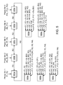
- FIG. 5 illustrates a technique for obtaining a volumetric image in accordance with some embodiments
- FIG. 6 illustrates another technique for obtaining a volumetric image in accordance with other embodiments
- FIG. 7 illustrates a system for obtaining a volumetric image in accordance with some embodiments
- FIG. 8 illustrates another radiation system in accordance with other embodiments.
- FIG. 9 is a block diagram of a computer system architecture, with which embodiments described herein may be implemented.
- FIG. 1 illustrates an imaging system 10 in accordance with some embodiments.
- the system 10 includes a gantry 12 , and a panel 14 for supporting a patient 28 .
- the gantry 12 includes a radiation source 20 that projects a beam 26 of radiation (e.g., x-rays) towards a detector 24 on an opposite side of the gantry 12 while the patient 28 is positioned at least partially between the radiation source 20 and the detector (imager) 24 .
- the beam of x-rays can be a cone beam or a fan beam.
- the detector 24 has a plurality of sensor elements configured for sensing a x-ray that passes through the patient 28 .
- the system 10 also includes a positioner (not shown) configured to move the radiation source 20 .
- the positioner may be configured to rotate the gantry 12 to thereby turn the radiation source 20 along a circular or an arc path.
- the system 10 also includes a control system 18 .
- the control system 18 includes a processor 54 , such as a computer processor, coupled to a control 40 .
- the control system 18 may also include a monitor 56 for displaying data and an input device 58 , such as a keyboard or a mouse, for inputting data.
- the operation of the radiation source 20 and the gantry 12 are controlled by the control 40 , which provides power and timing signals to the radiation source 20 , and controls a rotational speed and position of the gantry 12 , based on signals received from the processor 54 .
- the control 40 is shown as a separate component from the gantry 12 and the processor 54 , in alternative embodiments, the control 40 can be a part of the gantry 12 or the processor 54 .
- the radiation source 20 is a diagnostic radiation source for providing diagnostic energy.
- the radiation source 20 may be a treatment radiation source for providing treatment energy.
- the treatment energy is generally those energies of 160 kilo-electron-volts (keV) or greater, and more typically 1 mega-electron-volts (MeV) or greater
- diagnostic energy is generally those energies below the high energy range, and more typically below 160 keV.
- the treatment energy and the diagnostic energy can have other energy levels, and refer to energies that are used for treatment and diagnostic purposes, respectively.
- the radiation source 20 is able to generate X-ray radiation at a plurality of photon energy levels within a range anywhere between approximately 10 keV and approximately 20 MeV.
- the radiation source 20 may be a treatment radiation source, in which cases, the imager 24 may be an on-board imager.
- the system 10 is not limited to the configuration described above, and that the system 10 may have other configurations in other embodiments.
- the system 10 may have a different shape.
- the radiation source 20 of the system 10 may have different ranges of motions and/or degrees of freedom.
- the radiation source 20 may be rotatable about the patient 28 completely through a 360° range, or partially through a range that is less than 360°.
- the radiation source 20 is translatable relative to the patient 28 .
- the system 10 may be a CT system.
- the system 10 may be a radiation treatment system.
- the radiation source 20 is not limited to delivering diagnostic energy in the form of x-ray, and may deliver treatment energy for treating a patient.
- the gantry 12 of the system 10 may cooperate with the patient support 14 to achieve a spiral motion.
- the gantry 12 may rotate while the patient support 14 is being translated along its longitudinal axis.
- the gantry 12 rotates about the patient 28 at different gantry angles, so that the radiation source 20 and the imager 24 may be used to obtain images at different gantry angles.
- the system 10 is operated to obtain images at different gantry angles, the patient 28 is breathing.
- the resulting images at different gantry angles may correspond to different phases of a breathing cycle for the patient 28 .
- the generated projection images at different gantry angles are stored, e.g., in a memory, and the projection images are processed to sort the images so that images that correspond to a same phase or a same phase range of a breathing cycle are binned (e.g., associated with each other).
- the binned images for a specific phase of a respiratory cycle can then be used to reconstruct a digital volumetric image for that phase.
- the system 10 may optionally further include a patient position determining system 70 that includes a camera 80 and a marker block 82 having a plurality of markers 84 .
- the patient position determining system 70 is configured to determine amplitude and/or phase of a physiological movement of the patient 28 .
- the marker block 82 may be placed on the patient's chest, and the camera 80 is then used to view the markers 84 on the marker block 82 .
- the chest of the patient 28 will move up and down, and the marker block 82 will move correspondingly.
- the processor 54 may be configured to process the image(s) from the camera 80 to determine a position of the marker block 82 relative to some arbitrary reference coordinate. By continuously tracking the position of the marker block 82 , the processor 54 may determine the breathing amplitudes and/or phases of the breathing cycle that the patient 28 is going through. The determined amplitudes and/or phases may then be later used by the processor 54 to sort the images so that different sets of images correspond with respective phases or phase ranges of the breathing cycle, as similarly discussed.
- the camera 80 may be configured to use other things as marker(s), such as a patient's clothes, a physiological feature of the patient 28 , etc.
- the marker block 82 may be optional, and the patient position determining system 70 may not include any marker block 82 .
- Examples of a patient position determining system include Varian's RPM product, which is capable of recording amplitudes and phases of a breathing signal along with image data.
- the patient position determining system 70 may be other systems known in the art, such as a strain-gauge for measuring chest expansion, spirometer, etc., as long as the system can determine a state of the patient's 28 motion (e.g., breathing, cardiac motion, etc.).
- the patient position determining system 70 may use internal fiducial(s), such as implanted marker(s), anatomical feature(s), etc., for determining a state of a physiological cycle.
- FIG. 2 illustrates a method 200 for determining a volumetric image in accordance with some embodiments.
- the method 200 will be described with reference to the system 10 of FIG. 1 . However, it should be understood that the method 200 may be performed using other systems in other embodiments.
- volumetric image 300 a is generated using projection images P 1 , P 2
- volumetric image 300 b is generated using projection images P 3 , P 4 , P 5
- volumetric image 300 c is generated using projection images P 6 , P 7 , P 8
- volumetric image 300 d is generated using projection images P 9 , P 10
- volumetric image 300 e is generated using projection images P 11 , P 12 , P 13 .
- the projection images P 1 -P 13 may be generated using the system 10 (or another imaging system). While the projection images P 1 -P 13 are being generated, the patient is breathing. As a result, the projection images P 1 -P 13 may correspond to different respective phases of a breathing cycle. In the illustrated embodiments, for each projection image that is obtained while the patient is at a certain phase of a respiratory cycle, the processor 54 receives signals from the patient position monitoring system that indicate the corresponding phase, and the processor 54 associates the image with the corresponding phase. The images and their respective associated phases may be stored in a non-transitory medium for later processing. After the projection images P 1 -P 13 are generated, they may be sorted so that different projection images that are within a certain phase range are grouped.
- projection images P 1 , P 2 are grouped into phase bin 1
- projection images P 3 , P 4 , P 5 are grouped into phase bin 2
- projection images P 6 , P 7 , P 8 are grouped into phase bin 3
- projection images P 9 , P 10 are grouped into phase bin 4
- projection images P 11 , P 12 , P 13 are grouped into phase bin 5 .
- phase curve 402 also illustrates a phase curve 402 having phase values plotted against time, wherein the phase curve 402 corresponds with the amplitude curve 400 .
- a phase value of 0° (and 360°) represents a peak of an inhale state, and the phase value varies linearly between 0° and 360° in a physiological cycle.
- phase bin 1 is for a phase range of, e.g., 0°-72°
- phase bin 2 is for a phase range of, e.g., 72°-144°
- phase bin 3 is for a phase range of, e.g., 144°-216°
- phase bin 4 is for a phase range of, e.g., 216°-288°
- phase bin 5 is for a phase range of, e.g., 288°-360°.
- phase bins Nos. 1 - 5 all images with phase values from 0°-72°, 72°-144°, 144°-216°, 216°-288°, and 288°-360° will be grouped by the processor 54 into phase bins Nos. 1 - 5 , respectively.
- both of these projection images P 1 , P 2 may be sorted by the processor 54 so that they are grouped into phase bin 1 , which covers a phase range of 0°-72°.
- the projection images P 3 , P 4 , P 5 are generated when the patient is anywhere from 72°-144° in phase of a respiratory cycle, and thus, they are binned into phase bin 2 .
- the projection images P 6 , P 7 , P 8 are generated when the patient is anywhere from 144°-216° in phase of a respiratory cycle, and thus, they are binned into phase bin 3 .
- the projection images P 9 , P 10 are generated when the patient is anywhere from 216°-228° in phase of a respiratory cycle, and thus, they are binned into phase bin 4 .
- the projection images P 11 , P 12 , P 13 are generated when the patient is anywhere from 288°-360° in phase of a respiratory cycle, and thus, they are binned into phase bin 5 .
- the projection images P 11 , P 12 , P 13 may be generated during time durations 410 a , 410 b , for example, as shown in FIG. 4 . Note that the duration of the time periods 410 a , 410 b in the example are not necessarily equal, and that they may be different, depending on the breathing pattern of the patient 28 .
- the number of phase bins is not limited to five, and that in other embodiments, the number of phase bins for sorting the projection images may be less than five, or more than five.
- the phase ranges in the respective bins may be different from each other. In other embodiments, the phase ranges of the respective bins may overlap.
- phase bin 2 may be from 36° to 180°
- phase bin 3 may be from 108° to 252°
- phase bin 4 may be from 180° to 324°, etc.
- the phase bins may provide double coverage. In other cases, the coverage may be smaller or greater than double (two times).
- the number of bins may be user prescribed.
- a user may prescribe a certain number of phase bins (e.g., 5 phase bins) using the input device 58 .
- the processor 54 may generate each volumetric image 300 using a subset of the projection images in each phase bin (set), so that not all of the projection images in each set are used for the construction of the volumetric image 300 .
- the processor 54 may use all of the projection images in each set to construct the volumetric image 300 .
- the act of obtaining the volumetric images may be performed by a processor (e.g., processor 54 ) receiving the volumetric images.
- the act of obtaining the volumetric images may be performed by a processor (e.g., processor 54 ), which receives projection images, sorts the projection images into different sets (bins) based on their respective phases, and reconstruct the volumetric images using the respective sets of sorted projection images.
- the projection images and/or the volumetric images may be stored in a non-transitory medium for processing and/or retrieval later. Additionally, in some embodiments, the projection images and/or the volumetric images may be displayed in a screen (e.g., screen 56 ) for viewing by a user.
- the grouping of the projection images P is described as being based on phase. In other embodiments, the grouping of the projection images P may be based on amplitude of a respiratory cycle. For example, in some embodiments, the amplitude range 412 in a respiratory cycle may be divided into a number of amplitude bins (e.g., five amplitude bins, as shown in the figure). In such cases, projection images P that are generated when the amplitude is within the amplitude range of an amplitude bin are grouped into that bin. In other embodiments, the number of amplitude bins may be fewer than five, or more than five.
- the ranges (e.g., phase ranges, amplitude ranges, etc.) in the respective bins may be different from each other.
- the ranges in the respective bins may overlap.
- an additional volumetric image is determined using one or more of the projection images from each of the sets that correspond with the different respective phases of the physiological cycle (Item 204 ).
- the act of determining the additional volumetric image may be performed using a processor (e.g., the processor 54 ).
- an additional volumetric image for bin 1 may be determined using projection images from bin 1 , projection images from bin 2 , projection images from bin 3 , etc.
- FIG. 5 illustrates a technique of determining a volumetric image based on projection images from different bins using image registration in some embodiments.
- the technique of FIG. 5 may be an example of the Item 204 in the method 200 .
- each of the initial volumetric images 300 a - 300 e is registered with its adjacent volumetric image.
- an image registration R 1 may be determined between volumetric images 300 a , 300 b
- an image registration R 2 may be determined between volumetric images 300 b , 300 c
- an image registration R 3 may be determined between volumetric images 300 c , 300 d
- an image registration R 4 may be determined between volumetric images 300 d , 300 e
- an image registration R 5 may be determined between volumetric images 300 e , 300 a .
- each image registration R may be a deformation registration that represents a change between two adjacent volumetric images 300 .
- the deformation registration may include a plurality of vectors that represent how different parts in one volumetric image 300 are “deformed” to reach the configuration (e.g., size, shape, and/or position) of the corresponding parts in the adjacent volumetric image 300 .
- the determining of the registrations R may be performed by a processor (e.g., processor 54 ).
- the data regarding the registrations R may be stored in a non-transitory medium for later retrieval and/or processing.
- the data regarding the registrations R may also be displayed in a screen (e.g., screen 56 ) for viewing by a user.
- a new volumetric image may be determined using the determined registration(s) R.
- a new volumetric image 600 a which corresponds with the same phase or phase range of the volumetric image 300 a , may be determined using projection images from other phase bins (i.e., phase bins 2 - 5 ) and the determined registrations R.
- the same projection images P 1 , P 2 may be used to construct the additional volumetric image 600 a without any modification.
- the projection images P 3 , P 4 , P 5 are from a different phase bin (phase bin 2 )
- these projection images are modified into projection images P 3 ′, P 4 ′, P 5 ′ using the registration R 1 .
- the modification is possible because the registration R 1 between the volumetric image 600 a and 600 b provides information on how the two volumetric images 600 a , 600 b differ from each other.
- the registration information may be used to obtain modified projection images P 3 ′, P 4 ′, P 5 ′ (which correspond with the same gantry angles at which projection images P 3 , P 4 , P 5 were generated, respectively) as if they were generated for phase bin 1 .
- the volumetric image 300 b may be transformed by a deformation using registration R 1 resulting in a deformed volumetric image to reach the configuration (e.g., size, shape, and/or position) of the volumetric image 300 a .
- a forward projection of the deformed volumetric image at the same gantry angles for the respective projection images P 3 , P 4 , P 5 may then be performed to generate the modified projection images P 3 ′, P 4 ′, P 5 ′.
- the modified projection images P 3 ′, P 4 ′, P 5 ′ are then used to form the new volumetric image 600 a .
- the projection images P 3 ′, P 4 ′, P 5 ′ may be the only images used to construct the volumetric image 600 a .
- the projection images P 3 ′, P 4 ′, P 5 ′ may be used with other projection images (e.g., projection images from the phase bin 1 , and/or projection images from other phase bin(s)) to form the new volumetric image 600 a .
- the registration R 1 may be directly incorporated in the reconstruction of the volumetric image 600 a without performing the intermediate act of determining modified projection images P 3 ′, P 4 ′, P 5 ′ (which may obviate performing a forward projection and a back projection).
- the original projection images P 3 , P 4 , P 5 may be considered as being “used” to determine the new (additional) volumetric image 600 a.
- both registrations R 1 , R 2 are used for modifying the projection images P 6 , P 7 , P 8 because the registration R 2 provides information on how the volumetric image 300 c is different from the volumetric image 300 b , but not how the volumetric image 300 c is different from the volumetric image 300 a .
- both registrations R 1 , R 2 are used.
- the projection images P 9 , P 10 are from a different phase bin (phase bin 4 ), in order to use these projection images for constructing the volumetric image 600 a , these projection images are modified into projection images P 9 ′, P 10 ′ using the registrations R 1 , R 2 , R 3 .
- the registrations R 1 , R 2 , R 3 are used for modifying the projection images P 9 , P 10 because these three registrations provide sufficient information regarding how the volumetric image 300 d is different from the volumetric image 300 a .
- the registrations R 4 , R 5 may be used instead of using the registrations R 1 , R 2 , R 3 for modifying the projection images P 9 , P 10 . This is because the combination of registrations R 4 , R 5 also provides information on how the volumetric image 300 d is different from (or to be transformed to) the volumetric image 300 a , or vice versa.
- the projection images P 11 , P 12 , P 13 are from a different phase bin (phase bin 5 )
- these projection images are modified into projection images P 11 ′, P 12 ′, P 13 ′ using the registrations R 1 , R 2 , R 3 , R 4 .
- the registrations R 1 , R 2 , R 3 , R 4 are used for modifying the projection images P 11 , P 12 , P 13 because these four registrations provide sufficient information regarding how the volumetric image 300 e is different from the volumetric image 300 a .
- the registration R 5 may be used instead of using the registrations R 1 , R 2 , R 3 , R 4 for modifying the projection images P 11 , P 12 , P 13 . This is because the registration R 5 also provides information on how the volumetric image 300 e is different from (or to be transformed to) the volumetric image 300 a , or vice versa.
- the new volumetric image 600 a for phase bin 1 is determined using the projection images P 1 , P 2 that are associated with phase bin 1 , and the modified projection images P 3 ′-P 13 ′ from other phase bins 2 - 5 .
- such technique allows all of the projection images P 1 -P 13 to be used for determining the volumetric image 600 a .
- the determination of the volumetric image 600 a may be achieved by constructing the volumetric image 600 a using one or more of the projection images, that are less than all of the projection images, from each of the sets (phase bins).
- the same technique may be applied to determine additional volumetric images for other phase bins (i.e., any or all of phase bins 2 - 5 ).
- another new volumetric image 600 b that corresponds with phase bin 2 may be constructed using the original projection images P 3 , P 4 , P 5 associated with the phase bin 2 , and modified projection images P 1 ′, P 2 ′, and P 6 ′-P 13 ′.
- modified projection images P 1 ′, P 2 ′ are obtained by modifying projection images P 1 , P 2 using registration R 1 , which provides information on how the volumetric image 300 b is different from (or to be transformed to) the volumetric image 300 a , or vice versa.
- the modified projection images P 6 ′, P 7 ′, P 8 ′ are obtained by modifying projection images P 6 , P 7 , P 8 using registration R 2 , which provides information on how the volumetric image 300 b is different from (or to be transformed to) the volumetric image 300 c , or vice versa.
- the modified projection images P 9 ′, P 10 ′ are obtained by modifying projection images P 9 , P 10 using the combination of registrations R 2 , R 3 , which provides information on how the volumetric image 300 b is different from (or to be transformed to) the volumetric image 300 d , or vice versa.
- the modified projection images P 11 ′, P 12 ′, P 13 ′ are obtained by modifying projection images P 11 , P 12 , P 13 using the combination of registrations R 2 , R 3 , R 4 , which provides information on how the volumetric image 300 b is different from (or to be transformed to) the volumetric image 300 e , or vice versa.
- the projection images P 11 , P 12 , P 13 may be modified using the combination of registrations R 1 , R 5 , which also provides information on how the volumetric image 300 b is different from (or to be transformed to) the volumetric image 300 e , or vice versa.
- one or more of the new volumetric images 600 a - 600 e may be determined using one or more of the projection images, but not all, from each amplitude bin. Also, instead of having equal sizes, in some embodiments, the amplitude ranges in the respective bins may be different from each other. In other embodiments, the amplitude ranges of the respective bins may overlap.
- bins that may be used with the method 200 are not limited to the phase bins and amplitude bins described in the above examples, and that other types of bins may be used in other embodiments.
- a new volumetric image 600 may be constructed for any arbitrary phase or phase ranges (or for any arbitrary amplitude or amplitude ranges) of a physiological cycle using interpolation techniques. Also, in some embodiments, via the same interpolation techniques, the processor may perform a deformation specifically for any projection image in order to consider residual motion within a bin.
- the processor may be configured to calculate a combined matrix by multiplying R 1 with R 2 , and then with R 3 , and then with R 4 . This results in the projection images being sequentially modified as additional registration R is being applied.
- registrations R between adjacent images are combined.
- the processor e.g., processor 54
- the processor may be configured to replace each combination of registrations by the resulting deformation registration of the respective volumetric images 300 (which are not adjacent).
- the combined registration of R 1 , R 2 may be replaced by the deformation registration between volumetric images 300 a , 300 c (wherein the volumetric image 300 c is not adjacent to the volumetric image 300 a ).
- an image registration R 1 may be determined between volumetric images 300 a , 650
- an image registration R 2 may be determined between volumetric images 300 b , 650
- an image registration R 3 may be determined between volumetric images 300 c , 650
- an image registration R 4 may be determined between volumetric images 300 d , 650
- an image registration R 5 may be determined between volumetric images 300 e , 650 .
- each image registration R may be a deformation registration that represents a change between two volumetric images.
- the deformation registration may include a plurality of vectors that represent how different parts in one volumetric image 300 are “deformed” to reach the configuration (e.g., size, shape, and/or position) of the corresponding parts in the reference image 650 , or vice versa.
- the determining of the registrations R may be performed by a processor (e.g., processor 54 ).
- the data regarding the registrations R may be stored in a non-transitory medium for later retrieval and/or processing.
- the data regarding the registrations R may also be displayed in a screen (e.g., screen 56 ) for viewing by a user.
- the reference image 650 may be a volumetric image that was pre-determined, such as from a previous imaging session. In other embodiments, the reference image 650 may be any one of the volumetric images 300 a - 300 e . Also, in some embodiments, the reference image 650 may be arbitrarily selected from the volumetric images 300 a - 300 e . In other embodiments, the reference image 650 may be selected based on certain criteria.
- a new volumetric image may be determined using the determined registration(s) R.
- a new volumetric image 600 a which corresponds with the same phase or phase range of the volumetric image 300 a , may be determined using projection images from other phase bins (i.e., phase bins 2 - 5 ) and the determined registrations R.
- the same projection images P 1 , P 2 may be used to construct the additional volumetric image 600 a without any modification.
- both registrations R 1 , R 2 are used for modifying the projection images P 3 , P 4 , P 5 because the registration R 2 provides information on how the volumetric image 300 b is different from the reference volumetric image 650 , but not how the reference image 650 is different from the volumetric image 300 a .
- both registrations R 1 , R 2 are used.
- both registrations R 1 , R 3 are used for modifying the projection images P 6 , P 7 , P 8 because the registration R 3 provides information on how the volumetric image 300 c is different from the reference volumetric image 650 , but not how the reference image 650 is different from the volumetric image 300 a .
- both registrations R 1 , R 3 are used.
- both registrations R 1 , R 4 are used for modifying the projection images P 9 , P 10 because the registration R 4 provides information on how the volumetric image 300 d is different from the reference volumetric image 650 , but not how the reference image 650 is different from the volumetric image 300 a .
- both registrations R 1 , R 4 are used.
- both registrations R 1 , R 5 are used for modifying the projection images P 11 , P 12 , P 13 because the registration R 5 provides information on how the volumetric image 300 e is different from the reference volumetric image 650 , but not how the reference image 650 is different from the volumetric image 300 a .
- both registrations R 1 , R 5 are used.
- the new volumetric image 600 a for phase bin 1 is determined using the projection images P 1 , P 2 that are associated with phase bin 1 , and the modified projection images P 3 ′-P 13 ′ from other phase bins 2 - 5 .
- such technique allows all of the projection images P 1 -P 13 to be used for determining the volumetric image 600 a .
- the determination of the volumetric image 600 a may be achieved by constructing the volumetric image 600 a using one or more of the projection images, that are less than all of the projection images, from each of the sets (phase bins).
- the same technique may be applied to determine additional volumetric images for other phase bins (i.e., any or all of phase bins 2 - 5 ).
- another new volumetric image 600 b that corresponds with phase bin 2 may be constructed using the original projection images P 3 , P 4 , P 5 associated with the phase bin 2 , and modified projection images P 1 ′, P 2 ′, and P 6 ′-P 13 ′.
- modified projection images P 1 ′, P 2 ′ are obtained by modifying projection images P 1 , P 2 using a combination of the registrations R 1 , R 2 , which provides information on how the volumetric image 300 b is different from (or to be transformed to) the volumetric image 300 a , or vice versa.
- the modified projection images P 6 ′, P 7 ′, P 8 ′ are obtained by modifying projection images P 6 , P 7 , P 8 using a combination of the registrations R 2 , R 3 , which provides information on how the volumetric image 300 c is different from (or to be transformed to) the volumetric image 300 b , or vice versa.
- the modified projection images P 9 ′, P 10 ′ are obtained by modifying projection images P 9 , P 10 using the combination of registrations R 2 , R 4 , which provides information on how the volumetric image 300 d is different from (or to be transformed to) the volumetric image 300 b , or vice versa.
- the modified projection images P 11 ′, P 12 ′, P 13 ′ are obtained by modifying projection images P 11 , P 12 , P 13 using the combination of registrations R 2 , R 5 , which provides information on how the volumetric image 300 e is different from (or to be transformed to) the volumetric image 300 b , or vice versa.
- each of the volumetric images 600 in the sequence is determined (e.g., constructed) using all of the projection images P 1 -P 13 from the different phase bins 1 - 5 . This is advantageous because it allows a full dose usage in the determination of the sequence of volumetric images.
- one or more of the new volumetric images 600 a - 600 e may be determined using one or more of the projection images, but not all, from each set (e.g., phase bin).
- modified projection images are generated using registration(s) R, and the modified projection images are then used to determine the new volumetric image 600 .
- the determination of the modified projection images is not required.
- the processor e.g., the processor 54
- the determination of the additional volumetric image 600 for a given bin involves using a volumetric image 300 for another bin, and because the volumetric image 300 for the other bin is based on projection images for that other bin, it may be said that the determination of the additional volumetric image 600 involves using projection images from other bin.
- the embodiments of the technique of FIG. 6 are advantageous because the determination of each of the new volumetric images 600 a - 600 e does not involve using more than two registrations R.
- projection images P that spread across a complete phase range (e.g., 0°-360°) of the physiological cycle are used to construct each new volumetric image 600 .
- projection images P from a complete phase range instead of using projection images P from a complete phase range, projection images P from at least 50% of the complete phase range of the physiological cycle may be used.
- the volumetric image 600 a may be constructed using projection images from any three of the five phase bins 1 - 5 (e.g., from phase bins 1 , 2 , 3 , or from phase bins 1 , 3 , 5 , etc.).
- the volumetric image 600 may be constructed using projection images from only two of the sets (e.g., phase bins).
- the volumetric image 600 may be constructed from two projection images that are separated by a phase range that is at least 25% of a complete phase range for the physiological cycle.
- projection images P from a complete phase range instead of using projection images P from a complete phase range, projection images P from at least 90% of the complete phase range of the physiological cycle may be used.
- projection images P that spread across a total amplitude range of the physiological cycle may be used to construct each new volumetric image 600 .
- projection images P from the total amplitude range instead of using projection images P from the total amplitude range, projection images P from at least 50% of the total amplitude range of the physiological cycle may be used.
- the volumetric image 600 a may be constructed using projection images from any three of the five amplitude bins 1 - 5 .
- the volumetric image 600 may be constructed using projection images from only two of the sets (e.g., amplitude bins).
- the volumetric image 600 may be constructed from two projection images that are separated by an amplitude range that is at least 25% of a complete amplitude range for the physiological cycle.
- projection images P from a complete amplitude range instead of using projection images P from a complete amplitude range, projection images P from at least 90% of the complete amplitude range of the physiological cycle may be used.
- bins that may be used with the method 200 are not limited to the phase bins and amplitude bins described in the above examples, and that other types of bins may be used in other embodiments.
- the number of projection images from the corresponding bin (e.g., phase bin, amplitude bin, etc.) used by the processor to construct the volumetric image 600 may be more than the number of projection images from that bin to construct the initial volumetric image 300 . In other embodiments, the number of projection images from the corresponding bin used by the processor to construct the volumetric image 600 may be equal to the number of projection images from that bin used to construct the initial volumetric image 300 . In further embodiments, the number of projection images from the corresponding bin used by the processor to construct the volumetric image 600 may be less than the number of projection images from that bin used to construct the initial volumetric image 300 .
- a subset of all of the available projection image may be used to construct a new volumetric image 600 .
- the volumetric image 600 may be determined using at least 50%, and more preferably at least 75%, and even more preferably at least 90%, of all of the projection images from all of the sets (e.g., phase bins, amplitude bins, etc.).
- the projection images at the different bins may be all generated during an image session (e.g., in a day). For example, all of the projection images at the different bins may be generated while the patient 28 is at the patient support 14 . In such cases, the projection images at the different bins may be generated in a sequence by rotating the gantry 12 to place the radiation source 20 at different gantry angles. In other embodiments, projection images at the different bins (e.g., different phase bins, amplitude bins, etc.) may be generated from different image sessions.
- images generated while the patient's physiological cycle is anywhere from 0°-90° in phase taken in day 1 may be binned together with images for the same phase range (i.e., images generated while the patient's physiological cycle is anywhere from 0°-90°) taken in day 2.
- such technique may be employed to reduce the radiation dose for the patient. For example, after obtaining some projection images (from previous imaging sessions that occurred in one or more days), the patient may be deemed as having predictable breathing motion, and it may not be necessary to obtain all of the projection images in any further imaging session(s) (e.g., in the current imaging session). In some embodiments, in the current imaging session, the radiation system 10 may be used to obtain a reduced number of projection images.
- the reduced number of projection images may be used in conjunction with the previously obtained projection images to obtain new registrations R.
- the previously created registrations R may be relied upon and re-used, and the projection images obtained in the current imaging session may be used as verification for the previously created registrations R.
- the screen 56 may display one or more information that is involved in the method 200 .
- the screen 56 may display the original projection image(s) P, the modified projection image(s), the new volumetric image(s) 600 , or combination of the foregoing.
- the new volumetric images 600 may be displayed in a sequence to form a video.
- one or more information that is involved in the method 200 may be stored in a non-transitory medium for later processing and/or for retrieval.
- a non-transitory medium may store the original projection image(s) P, the modified projection image(s), the new volumetric image(s) 600 , etc.
- the volumetric images 600 may be stored in a sequence in a form of a video.
- FIG. 7 illustrates a system 700 for performing the method 200 in accordance with some embodiments.
- the system 700 may be implemented using hardware, software, or combination of both.
- the system 700 may be implemented using a processor (e.g., the processor 54 ), such as a general processor that is specifically configured to perform various functions (e.g., construction of volumetric image(s), deformation registration, modification of projection images, etc.) described herein.
- the system 700 may be implemented using an ASIC.
- the system 700 may be implemented using a computer system.
- the system 700 includes a module 702 for obtaining volumetric image(s), a module 704 for determining registration between volumetric images, a module 706 for applying the determined registration to projection images, and a module 708 for determining new (additional) volumetric image(s).
- the module 702 is configured (e.g., built and/or programmed) to perform the functions described with reference to Item 202 of method 200 .
- the module 702 may be configured to obtain the volumetric image(s) 300 by receive the volumetric image(s) 300 .
- the module 702 may be configured to obtain the volumetric image(s) 300 by performing image reconstruction using projection images.
- the module 702 may be configured to use a subset (i.e., not all) of the projection images in each set (e.g., phase bins, amplitude bin, etc.) to construct a volumetric image 300 . In other embodiments, the module 702 may be configured to use all of the projection images in each set to construct a volumetric image 300 .
- the module 704 is configured (e.g., built and/or programmed) to determine registration between volumetric images, such as between two adjacent volumetric images 300 like that described with reference to FIG. 5 , or between a volumetric image 300 and a reference image 650 like that described with reference to FIG. 6 .
- any of the functions regarding image registration (e.g., deformable registration) described with reference to the embodiments of FIG. 5 or 6 may be performed by the module 704 .
- the module 704 may be configured to replace each combination of registrations by the resulting deformation registration of the respective volumetric images 300 (which are not adjacent).
- the combined registration of R 1 , R 2 may be replaced by the deformation registration between volumetric images 300 a , 300 c (wherein the volumetric image 300 c is not adjacent to the volumetric image 300 a ).
- the module 706 is configured (e.g., built and/or programmed) to apply the determined registration(s) R for modifying the projection images P, like that described with reference to the method 200 .
- the module 706 may be configured to apply different registration(s) to the projection images in different sets, like that described with reference to the embodiments of FIG. 5 or 6 , to thereby determine one or more modified projection images.
- the module 708 is configured (e.g., built and/or programmed) to use the modified projection images to construct a new (additional) volumetric image, like that described with reference to Item 204 of the method 200 , and the technique of FIG. 5 or 6 .
- the module 708 may be configured to construct a volumetric image 600 for a particular bin (e.g., phase bin, amplitude bin, etc.) using projection images from that bin, as well as projection images from other bins.
- the number of projection images from the corresponding bin used by the module 708 to construct the volumetric image 600 may be more than the number of projection images from that bin used by the module 702 to construct the initial volumetric image 300 .
- the number of projection images from the corresponding bin used by the module 708 to construct the volumetric image 600 may be equal to the number of projection images from that bin used by the module 702 to construct the initial volumetric image 300 .
- the items 706 , 708 may be combined, in which cases, the registration(s) R may be directly incorporated in the construction of a new (additional) volumetric volume without performing the intermediate act of modifying the projection images P.
- the deformation registration has been described as being performed in an image space to estimate motion (motion vector fields).
- the registration e.g., deformation registration
- the module 702 is not required, and the module 704 is configured to perform deformation registration(s) between projection images in the different respective bins (e.g., phase bins, amplitude bins, etc.). The registration(s) may then be used to determine a new volumetric image 600 .
- 4D CT/CBCT images may have noise that is associated with an amount of dose delivered to the patient being imaged.
- one objective of an imaging procedure for 4D CT/CBCT may be to use as little dose as possible.
- using less dose generally results in higher noise, and lower image quality.
- the noise may be reduced by increasing dose to patient, such technique may result in undesirable additional dose to the patient.
- Embodiments described herein may allow noise in 4D CT/CBCT images to be reduced without increasing dose to the patient.
- the resulting volumetric image may have less noise without increasing dose to the patient.
- image(s) from different phase(s) of a motion cycle may be used to reduce noise for an image at a certain bin (e.g., phase bin, amplitude bin, etc.).
- the processor e.g., processor 54
- the processor may be configured to deform an image (e.g., a reconstructed 3D image, or a slice of such 3D image) from another bin (source image) to look like the subject image.
- the processor may perform a deformation registration between the source image and the subject image. Then the processor may perform a local-regional analysis to determine a similarity between the source image and the subject image.
- the processor uses the determined similarity to determine a mixing weight, which is then applied by the processor to form a blended composite image using information from the source image and the subject image.
- a mixing weight is particularly beneficial if image at different bin does not change significantly, or if image at different bin may be accurately deformed to look like that in the subject image.
- the deformed image may be significantly different from the subject image.
- this technique may set the blending weight of the deformed image to 0.
- the determination of the composite image may be performed by the processor using projection image data (i.e., before reconstruction of the volumetric image).
- the processor may be configured to use the volumetric images to determine of the composite image.
- the processor may use an image from an adjacent bin (e.g., phase bin, amplitude bin, etc.) in the above technique. In other embodiments, instead of the image at the adjacent bin, the processor may use other image(s) at other bin(s) that is not immediately adjacent to the image at the current bin. Also, in some embodiments, the processor may apply different weight factors when using images from different bins.
- an adjacent bin e.g., phase bin, amplitude bin, etc.
- the above described technique may allow the subject image with relatively less noise to be obtained without increasing the dose to the patient.
- the same technique may be applied for other subject images (i.e., images for different phases or phase ranges) to obtain a set of 4D CT/CBCT images that are improved versions of the original subject images.
- the resulting 4D CT/CBCT data set with reduced noise may be compressed for storage.
- adjacent image slice(s) may be used to reduce noise for a particular image slice in a volumetric image.
- adjacent slice image is deformed to look like the subject image.
- local-regional analysis may be performed to determine similarity between the adjacent slice and the subject image.
- the determined similarity is then used to determine a mixing weight, which is then applied to form a blended composite image using the adjacent image slice and the subject image.
- Such technique is particularly beneficial if image at adjacent slice does not change significantly, or if image at adjacent slice may be accurately deformed to look like that in the subject image. In some cases the deformed adjacent slice may be significantly different from the subject image. In such cases, this technique may set the blending weight of the adjacent image slice to 0.
- the processor may be configured to use other image slice(s) that is not immediately next to the current slice. Also, in other embodiments, the processor may apply different weight factors when using different slice(s). For example, relatively less weight may be applied for slice that is further away in phase.
- One technique to perform the local-regional analysis is to prescribe a multi-dimensional physical distance-to-agreement criteria, and an image value difference criteria. Such may be achieved by entering the criteria into a processor (e.g., through a user interface). For each point in the deformed image, the corresponding point in the subject image is identified by the processor. Then the processor computes the distance between that point and the nearest point in the image falling within the acceptable image value range. If the difference in position is within the distance-to-agreement criteria, and the difference in grey scale is within the tolerance, then the two points are considered “similar,” and the two points are used to form a composite point. In some embodiments, the distance to agreement and image value criteria may be used by the processor to determine the mixing weight between the images. For example, the processor may be configured to average the grey scale of the two points. Alternatively, the processor may be configured to combine the grey scale of the two points with respective weight factors.
- the processor e.g., the processor 54
- the processor 54 may be configured to use different functions, e.g., continuous function, linear, exponential, etc., for local-regional analysis. For example, pixel in an image that is closer to the position of the pixel in the subject image may be given more weight by the processor in accordance with the function. Pixels in the image that are further away may have less weight (e.g., which decreases exponentially).
- local-regional analysis may be based on color instead of grey scale. For example, if the color of source pixel is within a certain prescribed tolerance from that of the subject pixel, then the processor may combine the two pixels.
- the local-regional analysis may be performed by the processor based on statistical data.
- the distance-to-agreement and tolerance parameters may be statistical distributions that are considered by the processor when performing the local-regional analysis.
- FIG. 8 illustrates another embodiment of the system 10 that may be used.
- the system 10 of FIG. 8 is a radiation system that includes a gantry 12 , a patient support 14 for supporting a patient, and a control system 18 for controlling an operation of the gantry 12 .
- the gantry 12 is in a form of an arm (e.g., a C-arm).
- the system 10 also includes a radiation source 20 that projects a beam 26 of radiation towards a patient 28 while the patient 28 is supported on support 14 , and optionally a collimator system 22 for controlling a delivery of the radiation beam 26 .
- the radiation source 20 can be configured to generate a cone beam, a fan beam, or other types of radiation beams in different embodiments.
- the radiation source 20 is a diagnostic radiation source for providing diagnostic energy.
- the radiation source 20 may be a treatment radiation source for providing treatment energy.
- processor such as the processor 54
- processors may refer to one or more processing units, such as one or more processors, which may or may not be a part of the system 10 .
- one or more functions described with reference to the processor 54 may be performed at least in part by the processor 54 , completely by the processor 54 , or completely by another processor (which may or may not be a part of the system 10 ).
- processor may include one or more processing units, and may refer to any device that is capable of performing mathematical computation implemented using hardware and/or software.
- first and second refer to two things/items that are different or separate, and therefore, do not necessarily refer to the order in which the things are generated or arranged.
- image needs not be limited to an image that is displayed visually, and may refer to image data that is stored.
- phase may refer to a single phase or a range of phases.
- amplitude may refer to a single amplitude or a range of amplitudes.
- a volumetric image is described as being determined “using” certain information (e.g., projection image(s), modified projection image(s), data (e.g., data regarding a registration, such as a matrix, a matrix value, a deformed volumetric image, a forward projection of a deformed image, etc.), etc.), it may refer to the information being used directly, or indirectly, to determine the volumetric image. Also, the information stated is not necessarily the only item that is “used” to determine the volumetric image.
- the volumetric image 600 is determined “using” a projection image P (because one of the projection images P is used in a process (in which the projection image P is modified) to determine the volumetric image 600 ).
- FIG. 9 is a block diagram that illustrates an embodiment of a computer system 1200 upon which embodiments described herein may be implemented.
- Computer system 1200 includes a bus 1202 or other communication mechanism for communicating information, and a processor 1204 coupled with the bus 1202 for processing information.
- the processor 1204 may be an example of the processor 54 of FIG. 1 , or another processor that is used to perform various functions described herein. In some cases, the computer system 1200 may be used to implement the processor 54 .
- the computer system 1200 also includes a main memory 1206 , such as a random access memory (RAM) or other dynamic storage device, coupled to the bus 1202 for storing information and instructions to be executed by the processor 1204 .
- main memory 1206 such as a random access memory (RAM) or other dynamic storage device
- the main memory 1206 also may be used for storing temporary variables or other intermediate information during execution of instructions to be executed by the processor 1204 .
- the computer system 1200 further includes a read only memory (ROM) 1208 or other static storage device coupled to the bus 1202 for storing static information and instructions for the processor 1204 .
- ROM read only memory
- a data storage device 1210 such as a magnetic disk or optical disk, is provided and coupled to the bus 1202 for storing information and instructions.
- the computer system 1200 may be coupled via the bus 1202 to a display 1212 , such as a cathode ray tube (CRT), for displaying information to a user.
- a display 1212 such as a cathode ray tube (CRT)
- An input device 1214 is coupled to the bus 1202 for communicating information and command selections to processor 1204 .
- cursor control 1216 is Another type of user input device
- cursor control 1216 such as a mouse, a trackball, or cursor direction keys for communicating direction information and command selections to processor 1204 and for controlling cursor movement on display 1212 .
- This input device typically has two degrees of freedom in two axes, a first axis (e.g., x) and a second axis (e.g., y), that allows the device to specify positions in a plane.
- the computer system 1200 may be used for performing various functions (e.g., calculation) in accordance with the embodiments described herein. According to one embodiment, such use is provided by computer system 1200 in response to processor 1204 executing one or more sequences of one or more instructions contained in the main memory 1206 . Such instructions may be read into the main memory 1206 from another computer-readable medium, such as storage device 1210 . Execution of the sequences of instructions contained in the main memory 1206 causes the processor 1204 to perform the process steps described herein. One or more processors in a multi-processing arrangement may also be employed to execute the sequences of instructions contained in the main memory 1206 . In alternative embodiments, hard-wired circuitry may be used in place of or in combination with software instructions to implement features of the embodiments described herein. Thus, embodiments described herein are not limited to any specific combination of hardware circuitry and software.
- Non-volatile media includes, for example, optical or magnetic disks, such as the storage device 1210 .
- a non-volatile medium may be considered to be an example of a non-transitory medium.
- Volatile media includes dynamic memory, such as the main memory 1206 .
- a volatile medium may be considered to be another example of a non-transitory medium.
- Transmission media includes coaxial cables, copper wire and fiber optics, including the wires that comprise the bus 1202 . Transmission media can also take the form of acoustic or light waves, such as those generated during radio wave and infrared data communications.
- Computer-readable media include, for example, a floppy disk, a flexible disk, hard disk, magnetic tape, or any other magnetic medium, a CD-ROM, any other optical medium, punch cards, paper tape, any other physical medium with patterns of holes, a RAM, a PROM, and EPROM, a FLASH-EPROM, any other memory chip or cartridge, a carrier wave as described hereinafter, or any other medium from which a computer can read.
- Various forms of computer-readable media may be involved in carrying one or more sequences of one or more instructions to the processor 1204 for execution.
- the instructions may initially be carried on a magnetic disk of a remote computer.
- the remote computer can load the instructions into its dynamic memory and send the instructions over a telephone line using a modem.
- a modem local to the computer system 1200 can receive the data on the telephone line and use an infrared transmitter to convert the data to an infrared signal.
- An infrared detector coupled to the bus 1202 can receive the data carried in the infrared signal and place the data on the bus 1202 .
- the bus 1202 carries the data to the main memory 1206 , from which the processor 1204 retrieves and executes the instructions.
- the instructions received by the main memory 1206 may optionally be stored on the storage device 1210 either before or after execution by the processor 1204 .
- the computer system 1200 also includes a communication interface 1218 coupled to the bus 1202 .
- the communication interface 1218 provides a two-way data communication coupling to a network link 1220 that is connected to a local network 1222 .
- the communication interface 1218 may be an integrated services digital network (ISDN) card or a modem to provide a data communication connection to a corresponding type of telephone line.
- ISDN integrated services digital network
- the communication interface 1218 may be a local area network (LAN) card to provide a data communication connection to a compatible LAN.
- LAN local area network
- Wireless links may also be implemented.
- the communication interface 1218 sends and receives electrical, electromagnetic or optical signals that carry data streams representing various types of information.
- the network link 1220 typically provides data communication through one or more networks to other devices.
- the network link 1220 may provide a connection through local network 1222 to a host computer 1224 or to equipment 1226 such as a radiation beam source or a switch operatively coupled to a radiation beam source.
- the data streams transported over the network link 1220 can comprise electrical, electromagnetic or optical signals.
- the signals through the various networks and the signals on the network link 1220 and through the communication interface 1218 which carry data to and from the computer system 1200 , are exemplary forms of carrier waves transporting the information.
- the computer system 1200 can send messages and receive data, including program code, through the network(s), the network link 1220 , and the communication interface 1218 .
Abstract
Description
Claims (45)
Priority Applications (6)
| Application Number | Priority Date | Filing Date | Title |
|---|---|---|---|
| US13/436,908 US9047701B2 (en) | 2012-03-31 | 2012-03-31 | 4D cone beam CT using deformable registration |
| EP13768872.7A EP2831785B1 (en) | 2012-03-31 | 2013-03-29 | 4d cone beam ct using deformable registration |
| JP2015503666A JP6353435B2 (en) | 2012-03-31 | 2013-03-29 | 4-dimensional cone beam CT using deformable registration |
| PCT/US2013/034706 WO2013149201A1 (en) | 2012-03-31 | 2013-03-29 | 4d cone beam ct using deformable registration |
| CN201380028555.0A CN104321773B (en) | 2012-03-31 | 2013-03-29 | Volume image acquisition method and device |
| JP2018036139A JP6714629B2 (en) | 2012-03-31 | 2018-03-01 | Four-dimensional cone-beam CT using deformable registration |
Applications Claiming Priority (1)
| Application Number | Priority Date | Filing Date | Title |
|---|---|---|---|
| US13/436,908 US9047701B2 (en) | 2012-03-31 | 2012-03-31 | 4D cone beam CT using deformable registration |
Publications (2)
| Publication Number | Publication Date |
|---|---|
| US20130259338A1 US20130259338A1 (en) | 2013-10-03 |
| US9047701B2 true US9047701B2 (en) | 2015-06-02 |
Family
ID=49235097
Family Applications (1)
| Application Number | Title | Priority Date | Filing Date |
|---|---|---|---|
| US13/436,908 Active 2033-04-27 US9047701B2 (en) | 2012-03-31 | 2012-03-31 | 4D cone beam CT using deformable registration |
Country Status (5)
| Country | Link |
|---|---|
| US (1) | US9047701B2 (en) |
| EP (1) | EP2831785B1 (en) |
| JP (2) | JP6353435B2 (en) |
| CN (1) | CN104321773B (en) |
| WO (1) | WO2013149201A1 (en) |
Cited By (3)
| Publication number | Priority date | Publication date | Assignee | Title |
|---|---|---|---|---|
| US20160174921A1 (en) * | 2014-12-19 | 2016-06-23 | Ion Beam Applications S.A. | Method and imaging system for determining a reference radiograph for a later use in radiation therapy |
| US20160213341A1 (en) * | 2015-01-27 | 2016-07-28 | Septimiu Edmund Salcudean | Dynamic computed tomography imaging of elasticity |
| US10062168B2 (en) | 2016-02-26 | 2018-08-28 | Varian Medical Systems International Ag | 5D cone beam CT using deformable registration |
Families Citing this family (10)
| Publication number | Priority date | Publication date | Assignee | Title |
|---|---|---|---|---|
| KR101638990B1 (en) * | 2014-03-26 | 2016-07-12 | 한양대학교 산학협력단 | Method and device for dose calculation |
| DE102015215584B4 (en) * | 2015-08-14 | 2022-03-03 | Siemens Healthcare Gmbh | Method and system for the reconstruction of planning images |
| US11172895B2 (en) * | 2015-12-07 | 2021-11-16 | Covidien Lp | Visualization, navigation, and planning with electromagnetic navigation bronchoscopy and cone beam computed tomography integrated |
| US9990711B2 (en) | 2016-01-25 | 2018-06-05 | Accuray Incorporated | Manipulation of a respiratory model via adjustment of parameters associated with model images |
| US10065049B2 (en) * | 2016-01-25 | 2018-09-04 | Accuray Incorporated | Presenting a sequence of images associated with a motion model |
| CN105816196A (en) * | 2016-05-13 | 2016-08-03 | 上海联影医疗科技有限公司 | Marking tape for 4DCT imaging and 4DCT imaging method |
| WO2018023024A1 (en) * | 2016-07-29 | 2018-02-01 | The Regents Of The University Of Colorado, A Body Corporate | Automated tracking of fiducial marker clusters in x-ray images |
| CN111275669B (en) * | 2020-01-13 | 2022-04-22 | 西安交通大学 | Priori information guided four-dimensional cone beam CT image reconstruction algorithm |
| WO2023011924A1 (en) * | 2021-08-02 | 2023-02-09 | Brainlab Ag | 2d/3d image registration using 2d raw images of 3d scan |
| WO2023062819A1 (en) * | 2021-10-15 | 2023-04-20 | 株式会社 東芝 | Imaging control system and imaging control method |
Citations (12)
| Publication number | Priority date | Publication date | Assignee | Title |
|---|---|---|---|---|
| US6865248B1 (en) * | 1999-09-25 | 2005-03-08 | Koninklijke Philips Electronics, N.V. | Method and device for acquiring a three-dimensional image data set of a moving organ of the body |
| WO2006003002A2 (en) | 2004-07-06 | 2006-01-12 | Elekta Ab (Publ) | Imaging internal structures |
| WO2006119623A1 (en) | 2005-05-09 | 2006-11-16 | Robarts Research Institute | System and method for generating dynamic ct images of a target within a subject that experiences motion |
| US20070025509A1 (en) * | 2005-07-13 | 2007-02-01 | Siemens Medical Solutions Usa, Inc. | 4-dimensional digital tomosynthesis and its applications in radiation therapy |
| US20070189591A1 (en) | 2005-07-22 | 2007-08-16 | Weiguo Lu | Method of placing constraints on a deformation map and system for implementing same |
| US20100201786A1 (en) * | 2006-05-11 | 2010-08-12 | Koninklijke Philips Electronics N.V. | Method and apparatus for reconstructing an image |
| US20110176723A1 (en) | 2010-01-15 | 2011-07-21 | Board Of Regents University Of Oklahoma | Motion Correction in Cone-Beam CT by Tracking Internal and External Markers Using Cone-Beam Projection From a kV On-Board Imager: Four-Dimensional Cone-Beam CT and Tumor Tracking Implications |
| US20110206178A1 (en) | 2007-05-17 | 2011-08-25 | Elekta Ab | On-line cone beam CT reconstruction |
| US20110299751A1 (en) | 2010-06-03 | 2011-12-08 | Varian Medical International Ag | Method and Apparatus to Facilitate Development of Therapeutic Treatment Plans |
| US20110311118A1 (en) | 2005-08-30 | 2011-12-22 | Cleveland Clinic Foundation | Techniques for 3-D Elastic Spatial Registration of Multiple Modes of Measuring a Body |
| US20120245453A1 (en) * | 2011-03-23 | 2012-09-27 | Erik John Tryggestad | Respiratory interval-based correlation and processing of dynamic imaging data |
| US20120281897A1 (en) * | 2011-05-03 | 2012-11-08 | General Electric Company | Method and apparatus for motion correcting medical images |
Family Cites Families (19)
| Publication number | Priority date | Publication date | Assignee | Title |
|---|---|---|---|---|
| JP3781834B2 (en) * | 1996-10-03 | 2006-05-31 | ジーイー横河メディカルシステム株式会社 | X-ray tomography method and X-ray tomography apparatus |
| JP3124254B2 (en) * | 1997-07-24 | 2001-01-15 | ジーイー横河メディカルシステム株式会社 | Radiation tomography equipment |
| US6937696B1 (en) * | 1998-10-23 | 2005-08-30 | Varian Medical Systems Technologies, Inc. | Method and system for predictive physiological gating |
| WO2001080184A1 (en) * | 2000-04-14 | 2001-10-25 | General Electric Company | Reconstruction of computed tomographic images using interpolation between projection views |
| US7182083B2 (en) * | 2002-04-03 | 2007-02-27 | Koninklijke Philips Electronics N.V. | CT integrated respiratory monitor |
| EP1723607B1 (en) * | 2004-03-02 | 2018-11-07 | Philips Intellectual Property & Standards GmbH | Motion compensation |
| EP1769743A4 (en) * | 2004-06-16 | 2010-09-29 | Hitachi Medical Corp | Radiotomograph |
| CN100583155C (en) * | 2004-06-18 | 2010-01-20 | 皇家飞利浦电子股份有限公司 | Artifact reduction |
| US8315450B2 (en) * | 2004-11-24 | 2012-11-20 | Wisconsin Alumni Research Foundation | Method and system for display of medical image data |
| US7792240B2 (en) * | 2005-01-18 | 2010-09-07 | Hitachi Medical Corporation | X-ray CT apparatus |
| DE102005036963B3 (en) * | 2005-08-05 | 2007-02-15 | Siemens Ag | Medical image recording method and associated device |
| JP5362361B2 (en) * | 2005-11-24 | 2013-12-11 | コーニンクレッカ フィリップス エヌ ヴェ | Motion compensated CT reconstruction for high contrast objects |
| JP2007216043A (en) * | 2007-04-11 | 2007-08-30 | Ge Yokogawa Medical Systems Ltd | X-ray ct apparatus |
| JP5317580B2 (en) * | 2008-08-20 | 2013-10-16 | 株式会社東芝 | X-ray CT system |
| EP2396765B1 (en) * | 2009-02-11 | 2016-03-30 | Koninklijke Philips N.V. | Group-wise image registration based on motion model |
| EP2422318B1 (en) * | 2009-04-15 | 2019-10-16 | Koninklijke Philips N.V. | Quantification of medical image data |
| US8755565B2 (en) * | 2009-11-04 | 2014-06-17 | Hitachi Medical Corporation | X-ray CT apparatus and image display method of X-ray CT apparatus |
| US20110148928A1 (en) * | 2009-12-17 | 2011-06-23 | General Electric Company | System and method to correct motion in gated-pet images using non-rigid registration |
| JP5743445B2 (en) * | 2010-07-13 | 2015-07-01 | 株式会社東芝 | Radiation computed tomography apparatus, medical image generation apparatus, and respiratory phase measurement apparatus |
-
2012
- 2012-03-31 US US13/436,908 patent/US9047701B2/en active Active
-
2013
- 2013-03-29 JP JP2015503666A patent/JP6353435B2/en active Active
- 2013-03-29 EP EP13768872.7A patent/EP2831785B1/en active Active
- 2013-03-29 CN CN201380028555.0A patent/CN104321773B/en active Active
- 2013-03-29 WO PCT/US2013/034706 patent/WO2013149201A1/en active Application Filing
-
2018
- 2018-03-01 JP JP2018036139A patent/JP6714629B2/en active Active
Patent Citations (12)
| Publication number | Priority date | Publication date | Assignee | Title |
|---|---|---|---|---|
| US6865248B1 (en) * | 1999-09-25 | 2005-03-08 | Koninklijke Philips Electronics, N.V. | Method and device for acquiring a three-dimensional image data set of a moving organ of the body |
| WO2006003002A2 (en) | 2004-07-06 | 2006-01-12 | Elekta Ab (Publ) | Imaging internal structures |
| WO2006119623A1 (en) | 2005-05-09 | 2006-11-16 | Robarts Research Institute | System and method for generating dynamic ct images of a target within a subject that experiences motion |
| US20070025509A1 (en) * | 2005-07-13 | 2007-02-01 | Siemens Medical Solutions Usa, Inc. | 4-dimensional digital tomosynthesis and its applications in radiation therapy |
| US20070189591A1 (en) | 2005-07-22 | 2007-08-16 | Weiguo Lu | Method of placing constraints on a deformation map and system for implementing same |
| US20110311118A1 (en) | 2005-08-30 | 2011-12-22 | Cleveland Clinic Foundation | Techniques for 3-D Elastic Spatial Registration of Multiple Modes of Measuring a Body |
| US20100201786A1 (en) * | 2006-05-11 | 2010-08-12 | Koninklijke Philips Electronics N.V. | Method and apparatus for reconstructing an image |
| US20110206178A1 (en) | 2007-05-17 | 2011-08-25 | Elekta Ab | On-line cone beam CT reconstruction |
| US20110176723A1 (en) | 2010-01-15 | 2011-07-21 | Board Of Regents University Of Oklahoma | Motion Correction in Cone-Beam CT by Tracking Internal and External Markers Using Cone-Beam Projection From a kV On-Board Imager: Four-Dimensional Cone-Beam CT and Tumor Tracking Implications |
| US20110299751A1 (en) | 2010-06-03 | 2011-12-08 | Varian Medical International Ag | Method and Apparatus to Facilitate Development of Therapeutic Treatment Plans |
| US20120245453A1 (en) * | 2011-03-23 | 2012-09-27 | Erik John Tryggestad | Respiratory interval-based correlation and processing of dynamic imaging data |
| US20120281897A1 (en) * | 2011-05-03 | 2012-11-08 | General Electric Company | Method and apparatus for motion correcting medical images |
Non-Patent Citations (9)
| Title |
|---|
| H. Wang et al., "Validation of an accelerated 'demons' algorithm for deformable image registration in radiation therapy", Phys. Med. Biol., vol. 50, No. 12, 20 pages, Jun. 2005. |
| International Search Report and Written Opinion dated Jul. 8, 2013 for PCT Application No. PCT/US2013/034706, 9 pages. |
| J. Lu et al., "Four-dimensional cone beam CT with adaptive gantry rotation and adaptive data sampling", Med. Phys., vol. 34, No. 9, 10 pages, Sep. 2007. |
| J.-P. Thirion, "Image matching as a diffusion process: An analogy with Maxwell's demons", Medical Image Analysis, vol. 2, No. 3, 18 pages , Sep. 1998. |
| S. Leng et al., "Streaking artifacts reduction in four-dimensional cone-beam computed tomography" Med. Phys., vol. 35, No. 10, 11 pages, Oct. 2008. |
| S. Rit et al., "On-the-fly motion-compensated cone-beam CT using an a priori model of the respiratory motion" Med. Phys. vol. 36, No. 6, 8 pages, Jun. 2009. |
| T. Li et al., "Enhanced 4D cone-beam CT with inter-phase motion model" Med. Phys., vol. 51, No. 9, 8 pages, Sep. 2007. |
| T. Li et al., "Four-dimensional cone-beam computed tomography using an on-board imager" Med. Phys., vol. 33, No. 10, 9 pages,Oct. 2006. |
| T. Li et al., "Motion correction for improved target localization with on-board cone-beam computed tomography" Phys. Med. Biol., vol. 51, No. 2, 2 pages, Feb. 2006. |
Cited By (5)
| Publication number | Priority date | Publication date | Assignee | Title |
|---|---|---|---|---|
| US20160174921A1 (en) * | 2014-12-19 | 2016-06-23 | Ion Beam Applications S.A. | Method and imaging system for determining a reference radiograph for a later use in radiation therapy |
| US9968321B2 (en) * | 2014-12-19 | 2018-05-15 | Ion Beam Applications S.A. | Method and imaging system for determining a reference radiograph for a later use in radiation therapy |
| US20160213341A1 (en) * | 2015-01-27 | 2016-07-28 | Septimiu Edmund Salcudean | Dynamic computed tomography imaging of elasticity |
| US10085703B2 (en) * | 2015-01-27 | 2018-10-02 | Septimiu Edmund Salcudean | Dynamic computed tomography imaging of elasticity |
| US10062168B2 (en) | 2016-02-26 | 2018-08-28 | Varian Medical Systems International Ag | 5D cone beam CT using deformable registration |
Also Published As
| Publication number | Publication date |
|---|---|
| CN104321773A (en) | 2015-01-28 |
| EP2831785B1 (en) | 2023-05-10 |
| EP2831785A1 (en) | 2015-02-04 |
| JP2018118073A (en) | 2018-08-02 |
| EP2831785A4 (en) | 2015-12-09 |
| JP2015517837A (en) | 2015-06-25 |
| CN104321773B (en) | 2017-05-17 |
| WO2013149201A1 (en) | 2013-10-03 |
| US20130259338A1 (en) | 2013-10-03 |
| JP6353435B2 (en) | 2018-07-04 |
| JP6714629B2 (en) | 2020-06-24 |
Similar Documents
| Publication | Publication Date | Title |
|---|---|---|
| US9047701B2 (en) | 4D cone beam CT using deformable registration | |
| US8396248B2 (en) | Sequential stereo imaging for estimating trajectory and monitoring target position | |
| US7711087B2 (en) | Patient setup using tomosynthesis techniques | |
| US9084888B2 (en) | Systems and methods for segmentation of radiopaque structures in images | |
| US8351671B2 (en) | Motion correction in nuclear imaging | |
| JP5734664B2 (en) | Image Restoration Method Using Dilution Constraint Correction | |
| US10981019B2 (en) | Systems and methods for triggering adaptive planning using knowledge based model | |
| US9517036B2 (en) | Radiation imaging using very slow rotational technique | |
| US10631778B2 (en) | Patient setup using respiratory gated and time resolved image data | |
| JP6165591B2 (en) | Image processing apparatus, treatment system, and image processing method | |
| US10729920B2 (en) | Systems and methods for quantifying radiation beam conformity | |
| US20140343401A1 (en) | Systems and methods for considering target motion in medical field | |
| US10062168B2 (en) | 5D cone beam CT using deformable registration | |
| US8594461B2 (en) | Image data compression and decompression | |
| US10390787B2 (en) | Optimization of image acquisition parameters for registration with reference image | |
| KR20150022176A (en) | An image reconstruction module, method of reconstruction of image and a radiation Imaging apparatus | |
| Beaudry | 4D cone-beam CT image reconstruction of Varian TrueBeam v1. 6 projection images for clinical quality assurance of stereotactic ablative radiotherapy to the lung | |
| EP2839783B1 (en) | Radiation imaging using very slow rotational technique |
Legal Events
| Date | Code | Title | Description |
|---|---|---|---|
| AS | Assignment |
Owner name: VARIAN MEDICAL SYSTEMS INTERNATIONAL AG, SWITZERLA Free format text: ASSIGNMENT OF ASSIGNORS INTEREST;ASSIGNORS:BERKUS, TIMO;OELHAFEN, MARKUS;KUNZ, PATRIK;REEL/FRAME:028438/0642 Effective date: 20120612 Owner name: FRIEDRICH-ALEXANDER-UNIVERSITAET ERLANGEN-NUERNBER Free format text: ASSIGNMENT OF ASSIGNORS INTEREST;ASSIGNORS:BREHM, MARCUS;KACHELRIESS, MARC;SIGNING DATES FROM 20120615 TO 20120616;REEL/FRAME:028438/0538 Owner name: VARIAN MEDICAL SYSTEMS, INC., CALIFORNIA Free format text: ASSIGNMENT OF ASSIGNORS INTEREST;ASSIGNOR:ZANKOWSKI, COREY E.;REEL/FRAME:028438/0728 Effective date: 20120611 |
|
| STCF | Information on status: patent grant |
Free format text: PATENTED CASE |
|
| MAFP | Maintenance fee payment |
Free format text: PAYMENT OF MAINTENANCE FEE, 4TH YEAR, LARGE ENTITY (ORIGINAL EVENT CODE: M1551); ENTITY STATUS OF PATENT OWNER: LARGE ENTITY Year of fee payment: 4 |
|
| MAFP | Maintenance fee payment |
Free format text: PAYMENT OF MAINTENANCE FEE, 8TH YEAR, LARGE ENTITY (ORIGINAL EVENT CODE: M1552); ENTITY STATUS OF PATENT OWNER: LARGE ENTITY Year of fee payment: 8 |
|
| AS | Assignment |
Owner name: SIEMENS HEALTHINEERS INTERNATIONAL AG, SWITZERLAND Free format text: CHANGE OF NAME;ASSIGNOR:VARIAN MEDICAL SYSTEMS INTERNATIONAL AG;REEL/FRAME:066352/0892 Effective date: 20220414 |