US9017806B2 - High airflow micro-truss structural apparatus - Google Patents
High airflow micro-truss structural apparatus Download PDFInfo
- Publication number
- US9017806B2 US9017806B2 US13/428,348 US201213428348A US9017806B2 US 9017806 B2 US9017806 B2 US 9017806B2 US 201213428348 A US201213428348 A US 201213428348A US 9017806 B2 US9017806 B2 US 9017806B2
- Authority
- US
- United States
- Prior art keywords
- micro
- struts
- truss
- truss layer
- contact
- Prior art date
- Legal status (The legal status is an assumption and is not a legal conclusion. Google has not performed a legal analysis and makes no representation as to the accuracy of the status listed.)
- Expired - Fee Related, expires
Links
Images


Classifications
-
- B—PERFORMING OPERATIONS; TRANSPORTING
- B32—LAYERED PRODUCTS
- B32B—LAYERED PRODUCTS, i.e. PRODUCTS BUILT-UP OF STRATA OF FLAT OR NON-FLAT, e.g. CELLULAR OR HONEYCOMB, FORM
- B32B3/00—Layered products comprising a layer with external or internal discontinuities or unevennesses, or a layer of non-planar form; Layered products having particular features of form
- B32B3/26—Layered products comprising a layer with external or internal discontinuities or unevennesses, or a layer of non-planar form; Layered products having particular features of form characterised by a particular shape of the outline of the cross-section of a continuous layer; characterised by a layer with cavities or internal voids ; characterised by an apertured layer
-
- A—HUMAN NECESSITIES
- A43—FOOTWEAR
- A43B—CHARACTERISTIC FEATURES OF FOOTWEAR; PARTS OF FOOTWEAR
- A43B13/00—Soles; Sole-and-heel integral units
- A43B13/14—Soles; Sole-and-heel integral units characterised by the constructive form
- A43B13/18—Resilient soles
-
- B—PERFORMING OPERATIONS; TRANSPORTING
- B32—LAYERED PRODUCTS
- B32B—LAYERED PRODUCTS, i.e. PRODUCTS BUILT-UP OF STRATA OF FLAT OR NON-FLAT, e.g. CELLULAR OR HONEYCOMB, FORM
- B32B3/00—Layered products comprising a layer with external or internal discontinuities or unevennesses, or a layer of non-planar form; Layered products having particular features of form
- B32B3/10—Layered products comprising a layer with external or internal discontinuities or unevennesses, or a layer of non-planar form; Layered products having particular features of form characterised by a discontinuous layer, i.e. formed of separate pieces of material
- B32B3/12—Layered products comprising a layer with external or internal discontinuities or unevennesses, or a layer of non-planar form; Layered products having particular features of form characterised by a discontinuous layer, i.e. formed of separate pieces of material characterised by a layer of regularly- arranged cells, e.g. a honeycomb structure
-
- B—PERFORMING OPERATIONS; TRANSPORTING
- B32—LAYERED PRODUCTS
- B32B—LAYERED PRODUCTS, i.e. PRODUCTS BUILT-UP OF STRATA OF FLAT OR NON-FLAT, e.g. CELLULAR OR HONEYCOMB, FORM
- B32B5/00—Layered products characterised by the non- homogeneity or physical structure, i.e. comprising a fibrous, filamentary, particulate or foam layer; Layered products characterised by having a layer differing constitutionally or physically in different parts
- B32B5/02—Layered products characterised by the non- homogeneity or physical structure, i.e. comprising a fibrous, filamentary, particulate or foam layer; Layered products characterised by having a layer differing constitutionally or physically in different parts characterised by structural features of a fibrous or filamentary layer
- B32B5/028—Net structure, e.g. spaced apart filaments bonded at the crossing points
-
- B—PERFORMING OPERATIONS; TRANSPORTING
- B32—LAYERED PRODUCTS
- B32B—LAYERED PRODUCTS, i.e. PRODUCTS BUILT-UP OF STRATA OF FLAT OR NON-FLAT, e.g. CELLULAR OR HONEYCOMB, FORM
- B32B5/00—Layered products characterised by the non- homogeneity or physical structure, i.e. comprising a fibrous, filamentary, particulate or foam layer; Layered products characterised by having a layer differing constitutionally or physically in different parts
- B32B5/22—Layered products characterised by the non- homogeneity or physical structure, i.e. comprising a fibrous, filamentary, particulate or foam layer; Layered products characterised by having a layer differing constitutionally or physically in different parts characterised by the presence of two or more layers which are next to each other and are fibrous, filamentary, formed of particles or foamed
- B32B5/24—Layered products characterised by the non- homogeneity or physical structure, i.e. comprising a fibrous, filamentary, particulate or foam layer; Layered products characterised by having a layer differing constitutionally or physically in different parts characterised by the presence of two or more layers which are next to each other and are fibrous, filamentary, formed of particles or foamed one layer being a fibrous or filamentary layer
-
- B—PERFORMING OPERATIONS; TRANSPORTING
- B32—LAYERED PRODUCTS
- B32B—LAYERED PRODUCTS, i.e. PRODUCTS BUILT-UP OF STRATA OF FLAT OR NON-FLAT, e.g. CELLULAR OR HONEYCOMB, FORM
- B32B2307/00—Properties of the layers or laminate
- B32B2307/70—Other properties
- B32B2307/724—Permeability to gases, adsorption
-
- B—PERFORMING OPERATIONS; TRANSPORTING
- B32—LAYERED PRODUCTS
- B32B—LAYERED PRODUCTS, i.e. PRODUCTS BUILT-UP OF STRATA OF FLAT OR NON-FLAT, e.g. CELLULAR OR HONEYCOMB, FORM
- B32B2437/00—Clothing
- B32B2437/02—Gloves, shoes
-
- B—PERFORMING OPERATIONS; TRANSPORTING
- B32—LAYERED PRODUCTS
- B32B—LAYERED PRODUCTS, i.e. PRODUCTS BUILT-UP OF STRATA OF FLAT OR NON-FLAT, e.g. CELLULAR OR HONEYCOMB, FORM
- B32B2479/00—Furniture
-
- B—PERFORMING OPERATIONS; TRANSPORTING
- B32—LAYERED PRODUCTS
- B32B—LAYERED PRODUCTS, i.e. PRODUCTS BUILT-UP OF STRATA OF FLAT OR NON-FLAT, e.g. CELLULAR OR HONEYCOMB, FORM
- B32B2605/00—Vehicles
-
- Y—GENERAL TAGGING OF NEW TECHNOLOGICAL DEVELOPMENTS; GENERAL TAGGING OF CROSS-SECTIONAL TECHNOLOGIES SPANNING OVER SEVERAL SECTIONS OF THE IPC; TECHNICAL SUBJECTS COVERED BY FORMER USPC CROSS-REFERENCE ART COLLECTIONS [XRACs] AND DIGESTS
- Y10—TECHNICAL SUBJECTS COVERED BY FORMER USPC
- Y10T—TECHNICAL SUBJECTS COVERED BY FORMER US CLASSIFICATION
- Y10T428/00—Stock material or miscellaneous articles
- Y10T428/12—All metal or with adjacent metals
- Y10T428/12347—Plural layers discontinuously bonded [e.g., spot-weld, mechanical fastener, etc.]
-
- Y—GENERAL TAGGING OF NEW TECHNOLOGICAL DEVELOPMENTS; GENERAL TAGGING OF CROSS-SECTIONAL TECHNOLOGIES SPANNING OVER SEVERAL SECTIONS OF THE IPC; TECHNICAL SUBJECTS COVERED BY FORMER USPC CROSS-REFERENCE ART COLLECTIONS [XRACs] AND DIGESTS
- Y10—TECHNICAL SUBJECTS COVERED BY FORMER USPC
- Y10T—TECHNICAL SUBJECTS COVERED BY FORMER US CLASSIFICATION
- Y10T428/00—Stock material or miscellaneous articles
- Y10T428/249921—Web or sheet containing structurally defined element or component
- Y10T428/249953—Composite having voids in a component [e.g., porous, cellular, etc.]
Definitions
- the described technology relates generally to a micro-truss structure and the use of the micro-truss structure in a material or apparatus for controlling the environmental state of a working surface (e.g., a micro-truss perspiration control layer for controlling airflow to a human body).
- a material or apparatus for controlling the environmental state of a working surface e.g., a micro-truss perspiration control layer for controlling airflow to a human body.
- honeycomb materials generally only allow airflow in a single direction.
- Commercial examples used in seating and bedding applications include Supracor® fusion bonded honeycomb.
- Such “vented” honeycombs generally have a much greater overall weight than non-vented honeycombs in order to make up for the degradation of its mechanical properties.
- Solid materials with defined airflow paths have also been used, but are generally uncomfortable. Although airflow is increased in the region of the airflow passages, areas where solid material contacts skin, generally become sweaty and uncomfortable.
- subjecting the above-discussed materials or structures to compressive forces generally causes densification of the materials or structures (e.g., reduction in the open volume of the material), which can close or reduce the size of airflow paths (or pathways), thereby reducing total airflow through the material.
- Thin, stretched web-like, or loose weave fabrics are designed to provide support through tension of the fabric and to provide airflow due to the loose weave. Tension is generally provided by a hard frame around the perimeter of the web or weave. Commercial examples include the Herman Miller® Aeron® Chair, and the SaddlecoTM FlowTM bike seat. These approaches do enable increased airflow, but have the disadvantage of being vulnerable to punctures and tears, limiting the overall usefulness in dynamic applications (e.g. sports).
- An ordered three-dimensional (3D) microstructure is an ordered 3D structure at the micrometer scale.
- polymer cellular materials that are mass produced are created through various foaming processes, which yield random (not ordered) 3D microstructures.
- Techniques do exist to create polymer materials with ordered 3D microstructures, such as stereolithography techniques; however, these techniques rely on a bottom-up, layer-by-layer approach which prohibits scalability.
- a stereolithography technique is a technique that builds a 3D structure in a layer-by-layer process. This process usually involves a platform (substrate) that is lowered into a photo-monomer (photopolymer) bath in discrete steps. At each step, a laser is scanned over the area of the photo-monomer that is to be cured (polymerized) for that particular layer. Once the layer is cured, the platform is lowered by a specific amount (determined by the processing parameters and desired feature/surface resolution) and the process is repeated until the full 3D structure is created.
- Hull et al. “Apparatus For Production Of Three-Dimensional Objects By Stereolithography,” U.S. Pat. No. 4,575,330, filed Aug. 8, 1984, which is incorporated by reference herein in its entirety.
- a polymer optical waveguide can be formed in certain photopolymers that undergo a refractive index change during the polymerization process. If a monomer that is photo-sensitive is exposed to light (typically UV) under the right conditions, the initial area of polymerization, such as a small circular area, will “trap” the light and guide it to the tip of the polymerized region due to this index of refraction change, further advancing that polymerized region. This process will continue, leading to the formation of a waveguide structure with substantially the same cross-sectional dimensions along its entire length.
- the existing techniques to create polymer optical waveguides have allowed only one or a few waveguides to be formed and these techniques have not been used to create a self-supporting three-dimensional structure by patterning polymer optical waveguides.
- Three-dimensional ordered polymer cellular structures have also been created using optical interference pattern techniques, also called holographic lithography; however, structures made using these techniques have an ordered structure at the nanometer scale and the structures are limited to the possible interference patterns, as described in Campbell et al., “Fabrication Of Photonic Crystals For The Visible Spectrum By Holographic Lithography,” NATURE, Vol. 404, Mar. 2, 2000, which is incorporated by reference herein in its entirety.
- micro-truss structures and methods of manufacturing micro-truss structures are described, for example, in U.S. patent application Ser. No. 12/455,449, which discloses a method of fabricating micro-truss structures having a fixed area, U.S. patent application Ser. No. 12/835,276, which discloses a method of continuously fabricating micro-truss structures according to a continuous process (e.g., a strip of arbitrary length), U.S. patent application Ser. No. 12/928,947, which discloses a compressible fluid filled micro-truss for energy absorption, and U.S. patent application Ser. No. 12/317,210, filed on Dec. 18, 2008, which discloses a functionally graded three-dimensional ordered open cellular microstructure and a method of making the same, each of which is incorporated by reference herein in its entirety.
- aspects of embodiments of the present invention are directed to an apparatus for maintaining an environmental state of a working surface.
- This environmental state can be provided, for example, by providing increased airflow to the working surface in contact with the apparatus.
- aspects of embodiments of the present invention are directed toward a micro-truss perspiration control layer apparatus for maintaining an environmental state of a surface of a body that generally has restricted air flow.
- the perspiration control layer includes 1) an ordered open-cellular polymer micro-truss material that is designed to allow in-plane air flow through the perspiration control layer, and 2) a porous contact support area between the article of interest and the relevant region of the body.
- the porous contact support area is designed to also provide substantial support to portions of the body.
- an apparatus for maintaining an environmental state of a working surface includes: a first micro-truss layer including: a plurality of first struts extending along a first direction; a plurality of second struts extending along a second direction; and a plurality of third struts extending along a third direction, the first, second, and third struts interpenetrating one another at a plurality of nodes, the first, second, and third struts interpenetrating one another at non-perpendicular angles, the apparatus having a contact surface configured to contact the working surface and having an open porosity configured to allow air to flow to the contact surface, wherein a total surface area of the contact surface is between about 1% and about 50% of a total surface area of the working surface.
- the first, second, and third struts may form a first plurality of unit cells.
- the apparatus may be less than five unit cells thick in a direction perpendicular to the contact surface.
- the unit cells may be about the same size.
- a ratio of the total surface area of the first micro-truss layer at the contact surface to the total surface area of the contact surface may be maintained to be substantially constant when the apparatus is under up to 50% densification strain.
- the contact surface may include a plurality of contact points spaced apart from one another, each of the contact points having a contact area in the range from about 100 square microns to about 10 square millimeters.
- the apparatus may further include a second micro-truss layer including: a plurality of fourth struts extending along a fourth direction; a plurality of fifth struts extending along a fifth direction; and a plurality of sixth struts extending along a sixth direction, the second micro-truss layer being located between the first micro-truss layer and the contact surface.
- a second micro-truss layer including: a plurality of fourth struts extending along a fourth direction; a plurality of fifth struts extending along a fifth direction; and a plurality of sixth struts extending along a sixth direction, the second micro-truss layer being located between the first micro-truss layer and the contact surface.
- the fourth, fifth, and sixth struts may form a second plurality of unit cells and the first, second, and third struts may form a first plurality of unit cells, each of the first unit cells being larger than each of the second unit cells.
- the first, second, and third struts may form a first three-dimensional pattern and the fourth, fifth, and sixth struts may form a second three-dimensional pattern, the second three-dimensional pattern differing from the first three-dimensional pattern.
- the apparatus may further include an interface connected with the first three-dimensional pattern and the second three-dimensional pattern.
- the first and second three-dimensional patterns may have order in three dimensions.
- the apparatus may further include a plurality of fourth struts extending in a direction perpendicular to the contact surface.
- the apparatus may be configured to be used with an article wearable by a person.
- a method of providing airflow to a working surface includes: configuring a first micro-truss layer to have an open porosity to allow air to flow through the first micro-truss layer, the first micro-truss layer including: a plurality of first struts extending along a first direction; a plurality of second struts extending along a second direction; and a plurality of third struts extending along a third direction, the first, second, and third struts interpenetrating one another at a plurality of nodes, the first, second, and third struts interpenetrating one another at non-perpendicular angles; and configuring the first micro-truss layer to be applied to the working surface, the first micro-truss layer being configured to contact the working surface at a contact surface, a total surface area of the micro-truss layer at the contact surface being between about 1% and about 50% of a total surface area of the working surface.
- the first, second, and third struts may be configured to form a first plurality of unit cells.
- the micro-truss layer may be less than five unit cells thick in a direction perpendicular to the contact surface.
- the unit cells may be about the same size.
- the contact surface may include a plurality of contact points spaced apart from one another, each of the contact points having a contact area in the range from about 100 square microns to about 10 square millimeters.
- a ratio of the total surface area of the contact surface to the total surface area of the working surface may be maintained to be substantially constant when the first micro-truss layer is under up to 50% densification strain.
- the first micro-truss layer may further include a plurality of fourth struts extending in a direction perpendicular to the contact surface.
- the first micro-truss layer may be a portion of: a helmet, an arm rest, a seat, a piece of clothing, a headband, a glove, a shoe insole, eyeglass frames, an undergarment, a mattress, or a mattress topper.
- a method of providing airflow to a working surface includes: configuring a first micro-truss layer to have an open porosity to allow air to flow through the first micro-truss layer, the first micro-truss layer including: a plurality of first struts extending along a first direction, a plurality of second struts extending along a second direction, and a plurality of third struts extending along a third direction, the first, second, and third struts interpenetrating one another at a plurality of nodes, the first, second, and third struts interpenetrating one another at non-perpendicular angles; configuring a second micro-truss layer to have an open porosity for wicking moisture through the second micro-truss layer, the second micro-truss layer including: a plurality of fourth struts extending along a fourth direction, a plurality of fifth struts extending along a fifth direction, and
- the fourth, fifth, and sixth struts may form a second plurality of unit cells and the first, second, and third struts may form a first plurality of unit cells, each of the first unit cells being larger than each of the second unit cells.
- FIG. 1 a is a perspective view of a micro-truss structure which is used in one embodiment of the present invention.
- FIG. 1 b is a side perspective view of a micro-truss structure which is used in one embodiment of the present invention.
- FIG. 1 c is a top perspective view of a micro-truss structure which is used in one embodiment of the present invention.
- FIG. 1 d is a perspective view of a micro-truss structure, having vertical struts, which is used in one embodiment of the present invention.
- FIG. 2 a is a perspective view of four angled struts and one vertical strut intersecting at a node according to one embodiment of the present invention.
- FIG. 2 b is a photograph of a micro-truss structure according to one embodiment of the present invention.
- FIG. 2 c is a perspective view of a micro-truss structure including a plurality of angled and vertical struts according to one embodiment of the present invention.
- FIGS. 2 d and 2 e are photographs of a micro-truss structure taken in cross-sectional and plan views, respectively, wherein the micro-truss structure includes a plurality of angled struts, thin vertical struts, and thick vertical struts according to one embodiment of the present invention.
- FIGS. 3 a and 3 b are schematic cross-sectional diagrams of a system for forming a structure from multiple waveguides created using a single collimated beam or multiple collimated beams passing through multiple apertures located at the bottom of the channel in both angled and vertical directions according to one embodiment of the present invention.
- FIGS. 3 c and 3 d are schematic cross-sectional diagrams of a system for forming a structure from multiple waveguides created using a single collimated beam or multiple collimated beams passing through multiple apertures located at the top of the channel in both angled and vertical directions according to one embodiment of the present invention.
- FIG. 4 a illustrates a square mask pattern (or a square mask aperture pattern) according to an embodiment of the present invention.
- FIG. 4 b illustrates a hexagonal mask pattern (or a hexagonal mask aperture pattern) according to an embodiment of the present invention.
- FIG. 5 a is a perspective view of four angled struts and one vertical strut intersecting at a node according to one embodiment of the present invention.
- FIG. 5 b is a photograph of a micro-truss structure according to one embodiment of the present invention.
- FIG. 5 c is a perspective view of four angled struts and one vertical strut intersecting at a node according to one embodiment of the present invention.
- FIG. 5 d is a photograph of a micro-truss structure taken in plan view according to one embodiment of the present invention.
- FIGS. 6 a , 6 b , and 6 c are illustrations of cross-sectional shapes of vertical struts according to some embodiments of the present invention.
- FIG. 7 is a schematic diagram of a micro-truss perspiration control layer according to a first embodiment of the present invention, in contact with and located between a body and an article of interest.
- FIG. 8 is a perspective view of a micro-truss layer having a face sheet located halfway through a unit cell according to a second embodiment of the present invention.
- FIG. 9 is a schematic diagram of a micro-truss perspiration control layer according to the second embodiment of the present invention, in contact with and located between a body and an article of interest.
- FIG. 10 is a schematic diagram of a micro-truss perspiration control layer according to a third embodiment of the present invention, in contact with and located between a body and an article of interest.
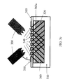
- FIG. 11 is a schematic view of a system for forming a functionally graded 3D ordered micro-truss structure according to an embodiment of the present invention.
- FIGS. 12 a , 12 b , and 12 c are 2D schematic diagrams of three-dimensional functionally graded micro-truss structures according to embodiments of the present invention.
- FIG. 13 is a schematic diagram illustrating the use of a micro-truss perspiration control layer with a seat according to one embodiment of the present invention.
- FIG. 14 is a schematic diagram illustrating the use of a micro-truss perspiration control layer with a shoe (e.g., as an insole of a shoe) according to one embodiment of the present invention.
- FIG. 15 is a photograph illustrating the use of a micro-truss perspiration control layer on a bicycle seat according to one embodiment of the present invention.
- aspects of embodiments of the present invention are directed to an apparatus for maintaining an environmental state of a working surface.
- This environmental state can be provided, for example, by providing increased airflow to the working surface in contact with the apparatus.
- aspects of embodiments of the present invention relate to a micro-truss based perspiration control layer apparatus for maintaining an environmental state of a surface of a body that generally has restricted air flow during a given activity by enhancing the air flow to that surface. Restricted air flow is a result of the region of the body being in physical contact with an article (e.g., clothing, seating, and control devices) used for that given activity.
- an article e.g., clothing, seating, and control devices
- the micro-truss perspiration control layer includes an ordered open-cellular polymer micro-truss material that serves as a porous contact support area between the article of interest and the relevant region of the body.
- the ordered open porosity in combination with the feasible size-scale of the micro-truss features, enable comfortable contact with the body without sacrificing air flow.
- Single micro-truss unit cells and structures including many unit cells according to embodiments of the present invention are shown in FIGS. 1 a , 1 b , 1 c , and 1 d . These unit cells are only some of many possible unit cell architectures that could be utilized for this application. Examples of additional possible unit cell architectures include, but are not limited to, structures described in Jacobsen et al, Acta Materialia 56 (2008) 2540-254, the entire disclosure of which is incorporated herein by reference.
- a three-dimensional ordered open-cellular micro-truss structure 10 is a self-supporting structure.
- the micro-truss 10 includes a plurality of angled struts (which may also be referred to as angled “truss elements,” “truss members,” or “polymer waveguides”) including first angled struts 12 , second angled struts 14 , and third angled struts 16 , which extend along a first direction A, a second direction B, and a third direction C, respectively.
- the micro-truss 10 also includes vertical struts 18 which extend along a vertical direction D.
- the first, second, and third angled struts 12 , 14 , 16 (and the vertical struts 18 in FIGS. 2 a , 2 b , 2 c , 2 d , and 2 e ) interpenetrate each other at nodes 20 to form a continuous material with a three-dimensional microstructure order.
- the micro-truss further includes fourth angled struts 22 which extend along a fourth direction E and which also interpenetrate with the first, second, and third angled struts 12 , 14 , and 16 and the vertical struts 18 at nodes 20 .
- the struts 12 , 14 , 16 , and 18 may include a photo-polymer material.
- the struts 12 , 14 , 16 , and 18 may be polymer optical waveguides.
- the continuous material may be continuously formed such that it lacks any interior boundaries, e.g., boundaries within the interpenetrating portions of struts 12 , 14 , 16 , and 18 .
- Each node 20 of the micro-truss structure 10 may be formed of the continuous material.
- the micro-truss 10 is formed by using a fixed light input (collimated UV light) to cure (polymerize) polymer optical waveguides, which can self-propagate in a 3D pattern. As such, the propagated polymer optical waveguides form the micro-truss 10 .
- some liquid polymers referred to as photopolymers, undergo a refractive index change during the polymerization process.
- the refractive index change can lead to a formation of polymer optical waveguides. If a monomer that is photo-sensitive is exposed to light (typically UV) under the right conditions, the initial area of polymerization, such as a small circular area, will “trap” the light and guide it to the tip of the polymerized region, further advancing that polymerized region. This process will continue, leading to the formation of a waveguide structure with substantially the same cross-sectional dimensions along its entire length.
- a mask with a two-dimensional pattern of apertures 340 (see FIGS. 4 a and 4 b ) is used with a light source and photo-monomer to create an ordered 3D polymer micro-truss structure (or an open-cell polymer micro-truss structure).
- FIG. 3 a is a schematic cross-sectional diagram of a system for forming a structure from multiple waveguides (or struts) created using a single collimated beam or multiple collimated beams passing through multiple apertures located at the bottom of the channel.
- a system for forming an ordered 3D polymer micro-truss structure includes one or more collimated light sources 300 , a channel/mold 310 having (or containing) a photo-monomer 320 that will polymerize at a wavelength of collimated light beams provided by the light sources 300 , and a patterning apparatus, such as a mask 330 with one or more apertures (open areas) 340 .
- Each of the apertures 340 has a given shape and dimension substantially matching a cross-sectional geometry of a strut (e.g. waveguide 360 a ).
- the mask 330 rests on the transparent substrate (or transparent plate) 350 that includes the bottom of the channel/mold 310 .
- the mask 330 is made of a lightweight, flexible, and opaque material such as polyethylene terephthalate (PET) film.
- PET polyethylene terephthalate
- the transparent substrate 350 may be made of a material (such as quartz) that is transparent to the light emitted from the collimated light sources, such that the collimated light shines into an exposure area 410 of the channel.
- the transparent substrate 350 acts as the mask 330 (e.g., portions of the transparent substrate 350 are opaque while other portions are transparent).
- the photo-monomer 320 fills the channel 310 above the mask 330 .
- different thicknesses of micro-truss structures can be achieved by filling the channel (or mold) 310 with photo-monomer 320 to the desired height. Once the collimated light source is applied, the intersecting polymer waveguides 360 a will grow upward from the surface of the mask 330 or the surface of the transparent substrate 350 , terminating at the free (e.g., upper) surface of the photo-monomer 320 in the channel 310 to form struts of the micro-truss structure.
- a 3D network (or micro-truss structure 360 ) can be formed because the intersecting polymer waveguides 360 a (or struts) will polymerize together, but will not interfere with waveguide propagation. Also, the spacing between the plurality of waveguides 360 a (or struts) corresponds with the pattern of the plurality of apertures 340 .
- the pattern of the apertures 340 may, for example, be in a square pattern as shown in FIG. 4 a and/or in a hexagonal pattern as shown in FIG. 4 b .
- the hole (aperture) spacing i.e., distance between apertures 340 in the mask 330 , and the number of waveguides 360 (or struts) formed from each of the apertures 340 , will determine the open volume fraction (i.e. open space) of the formed ordered 3D micro-truss structure (or the formed open-cell polymer micro-truss structure).
- an ordered 3D micro-truss structure 360 can be designed for various applications.
- the design parameters include: 1) the angle and pattern of the polymer struts with respect to one another, 2) the packing, or relative density of the resulting cell structure (or the open volume fraction), and 3) the cross-sectional shape and dimensions of the struts.
- the strut (or waveguide) diameter can range from 10 microns to 10 mm depending on the design criteria. In some embodiments, the strut diameter can range from 10 microns to 1 mm in order to improve user comfort.
- the length of the strut between nodes of interpenetrating struts can be between 5 and 15 times the diameter of the strut.
- the number of nodes, or the number of repeating unit cells, through the thickness of the 3D micro-truss structure can be designed.
- a micro-truss structure may have 1 ⁇ 2 unit cell to 10 unit cells through its thickness.
- the propagation distances and the size of the nodes of the interpenetrating waveguides (or struts) are unperturbed by the change in the index of refraction caused by polymerization, due to the method of formation of the ordered 3D micro-truss structure (or the open-cell polymer micro-truss structure).
- first, second, and third directions in which first, second, and third struts respectively extend include first, second, and third angles; the first, second, and third angles having first, second, and third inclinations ⁇ (e.g., with respect to the xz-plane as shown in FIG. 1 d ) and first, second, and third azimuths (e.g., about the y-axis as shown in FIG. 1 d ).
- the first, second, and third inclinations each may have the same or different values and each is in a range from 45° to 70° off the plane of the mask, inclusive.
- the vertical struts may have an inclination from 80° to 90° off the plane of the mask, inclusive (see, e.g., angle ⁇ in FIGS. 3 b and 3 d ).
- the inclinations ⁇ at which the first, second, and third struts extend may be determined by an angle ⁇ (see, e.g., FIG. 3 a ) at which the collimated light sources 300 are oriented with respect to the mask 330 such that the collimated light passes through the apertures 340 of the mask 330 at an angle ⁇ . Due to the refractive index change between air and the mask and monomer, in many instances, the angles ⁇ and ⁇ will not be the same.
- the struts further include vertical struts 360 b extending in a fourth direction with an inclination of substantially 90° (e.g., substantially perpendicular to the xz-plane).
- collimated light source 300 a is oriented to emit light in a direction substantially perpendicular with respect to the mask 330 .
- the vertical waveguides 360 b are formed after the angled waveguides 360 a (or struts) are formed.
- the vertical waveguides 360 b may be formed by using different collimated light sources 300 a or may be formed using the same collimated light sources 300 that are used to form the angled waveguides by repositioning the collimated light sources 300 to emit light in a direction substantially perpendicular to the mask 330 .
- the vertical waveguides 360 b are formed concurrently with the angled waveguides 360 b in which angled collimated light sources 300 and vertically oriented collimated light sources 300 a concurrently emit light through apertures 340 in the mask 330 .
- the vertical waveguides 360 b (or vertical struts 18 ) are described above and are illustrated in, for example, FIG. 1 d and FIG. 2 a as having a diameter (or cross sectional area) substantially equal to that of the angled waveguides 360 a (or angled struts 12 , 14 , and 16 ), according to other embodiments of the present invention, the vertical waveguides 360 b (or vertical struts 18 ) may have a different diameter (or cross sectional area) than that of the angled waveguides (or angled struts 12 , 14 , and 16 ). For example, in some embodiments the vertical waveguides 360 b may have a diameter in the range from 10 microns to 20 mm.
- the micro-truss structure includes vertical struts that are equal in diameter (or cross sectional area) to the angled struts as well as vertical struts that have diameters (or cross sectional areas) different from those of the angled struts.
- the diameters (or cross sectional areas) of the vertical struts of the micro-truss structure may all be different from the diameters (or cross sectional areas) of the angled struts.
- 2 d and 2 e are photographs of a side view and a top view, respectively, of a micro-truss structure having both angled struts 12 , 14 , and 16 and vertical struts 18 , the vertical struts 18 having a larger diameter (or cross sectional area) than the angled struts 12 , 14 , and 16 .
- the vertical waveguides 360 b may be formed using a mask having apertures that are larger or smaller than the apertures 340 of the mask 330 used to form the angled waveguides 360 a .
- the apertures of the mask used to form the vertical waveguides may have apertures that are spaced closer or farther apart than the apertures 340 of the mask 330 used to form the angled waveguides 360 a .
- the vertical waveguides may be formed through every node formed by the angled struts, or every second or third node formed by the angled struts.
- the vertical struts are arranged in a pattern that does not coincide with (e.g., is independent of) the pattern of the angled struts.
- a single mask having a plurality of apertures which may have different sizes may be used, and collimated light aimed perpendicular to the plane of the mask or at an angle is selectively emitted through the apertures of the mask.
- At least one digital mask may be used in place of the mask 330 below, above, or to either side of the channel 370 , or in any combination of these locations between the collimated light sources and the photo-monomer 320 .
- a digital mask is a display device which can be controlled to become opaque at some locations and transparent at other locations to the wavelength of light used to polymerize the photo-monomer, such as a liquid crystal display (LCD).
- LCD liquid crystal display
- the digital mask is located between the collimated light sources 300 and the transparent substrate 350 .
- the digital mask can be configured on-the-fly to display any variation of aperture sizes and patterns to produce the desired micro-truss structure 360 , eliminating the need for stopping fabrication to change masks.
- the digital mask may be used to from differently sized apertures for the angled struts and the vertical struts.
- the diameters (or cross sectional areas) and spacing of the vertical waveguides 360 b (or the vertical struts 18 ) can be varied independently of the diameters (or cross sectional areas) and spacing of the angled waveguides 360 a (or angled struts 12 , 14 , and 16 ). Therefore, the resistance of the micro-truss structure 10 to compression and shear forces can be adjusted independently based on the diameters (or cross sectional areas) and spacing of the vertical and angled waveguides 360 b and 360 a (or vertical and angled struts).
- the compression modulus (E) can be approximated by: E ⁇ E s (sin 4 ⁇ )( ⁇ / ⁇ s ) where ⁇ is the density of the micro-truss structure 10 , ⁇ s is the density of a solid material portion of the micro-truss structure 10 , and E s is a modulus of the solid material portion of the micro-truss structure 10 .
- the shear modulus (G) can be approximated by: G ⁇ ( E s /8)( ⁇ / ⁇ s )(sin 2 2 ⁇ )
- the angled struts may extend at an angle of about 45°.
- the angled struts may extend at different angles (e.g., between 45° and 90°) so that the angled struts may provide additional compression resistance in conjunction with the vertical struts or in order to reduce the distance in which the collimated light forming the angled struts must propagate.
- the resistance of a micro-truss structure 10 to shear and compression forces can be designed by varying the diameters (or cross sectional areas) and volume fraction of the vertical and angled struts, and varying the angle of the angled struts in accordance with the requirements of the applications to which the micro-truss structure will be applied.
- the strut diameter (or cross sectional area) may be in the range of about 10 ⁇ m to about 10 mm and the volume fraction ratio of vertical struts to angled struts could be between about 2% and about 70%.
- the angled struts 12 , 14 , and 16 and the vertical struts 18 intersect at the nodes 20 to form symmetrical angles in three-dimensions (three orthogonal directions).
- the symmetrical angles relative to the xz-plane can measure between 0° and 90°.
- each of the struts 12 , 14 , 16 defines an angle relative to a compression surface of the micro-truss 10 (e.g. a surface extending along a direction of the xz-plane), as well as with respect to the vertical struts 18 , and the respective angles defined by the angled struts 12 , 14 , 16 are substantially equal to one another.
- a compression surface of the micro-truss 10 e.g. a surface extending along a direction of the xz-plane
- the respective angles defined by the angled struts 12 , 14 , 16 are substantially equal to one another.
- embodiments of the present invention are not limited thereto.
- the polymer micro-truss structure is coated with a material different from the material of the polymer micro-truss structure itself, and the polymer micro-truss structure is removed to create a self-supporting structure having continuous but separated volumes.
- the polymer micro-truss structure may be coated with a metal such as nickel, aluminum, titanium, steel, and alloys thereof, which may improve the thermal conductivity of the anti-perspiration layer. Electro-deposition, slurry deposition, physical vapor deposition (PVD), or chemical vapor deposition (CVD) may be used to coat the polymer micro-truss structure.
- each of the hollow metal struts may have an inner diameter in the range of 10 microns to 10 mm and the thickness of the metal (or the wall thickness) is in the range of 1 micron to 1 mm.
- the resulting metal micro-truss structure may have a relative density in the range 0.5% to 30% with respect to a solid metal block.
- Architectural optimization refers to trading off unit cell design, strut diameter, length, angles, number of struts per unit cell, and materials to achieve a desired set of properties (e.g., a desired level of densification from an impact or pressure wave).
- the vertical truss struts 18 a have a non-circular cross section.
- the particular shape of the vertical truss struts 18 a depends on the number of angled struts which interpenetrate at the nodes 20 through which the vertical struts interpenetrate the angled struts 12 , 14 , 16 , and 22 .
- FIGS. 5 a , 5 b , 5 c , and 5 d four angled struts 12 , 14 , 16 , and 22 interpenetrate at nodes 20 . If the vertical strut 18 a is formed in a subsequent exposure step (after the four angled struts have been formed), the vertical strut 18 a has a “cross” or “plus” shape (see, e.g., FIG. 6 a ).
- FIGS. 6 a , 6 b , and 6 c illustrate cross-sectional shapes of the vertical struts according to other embodiments of the present invention.
- the vertical struts interpenetrating the angled struts at those nodes 20 would have n petals (where n is a natural number).
- the vertical struts would have three petals (e.g., a three-pointed star with truncated tips).
- FIGS. 6 a , 6 b , and 6 c illustrates the cross-sectional shape of the vertical struts in an embodiment in which five angled struts interpenetrate at the nodes.
- This effect diminishes as the vertical struts increase in diameter with respect to the diameter of the angled struts.
- the shape of the vertical struts becomes more cylindrical and is substantially cylindrical when the vertical struts have a diameter about ten times the diameter of the angled struts.
- the cross-sectional shape of the vertical struts may be a combination of a shape similar to those illustrated in FIGS. 6 a , 6 b , and 6 c and a circular shape.
- the radial size of the petals may decrease.
- FIG. 7 depicts an apparatus 710 for maintaining an environmental state of a surface (e.g., a micro-truss perspiration control structure), which includes a micro-truss structure 10 , according to one embodiment of the present invention, located between an article 740 and a body 750 , or other item of interest that is utilized for a given activity.
- a surface e.g., a micro-truss perspiration control structure
- the length of the struts 14 , 16 , and 18 between adjacent nodes may be between 5 to 15 times the diameter of the strut.
- the height c of an individual unit cell depends on the spacing between nodes of the apparatus 710 as well as the angles of inclination ⁇ of the struts 14 , 16 , and 18 .
- the apparatus 710 has a thickness (or height) h in the range from 1 ⁇ 2 to 10 unit cells.
- the apparatus 710 is bonded to the article 740 by a bonding material 742 (e.g., epoxy, polyurethane, etc.) along a bond line.
- a bonding material 742 e.g., epoxy, polyurethane, etc.
- the ability of air to flow through the micro-truss perspiration control layer is influenced by the total amount of open porosity (e.g., the open volume fraction), the representative shape of the unit cell that comprises the open porosity, and the distribution of the open porosity (i.e. unit cell size) of the apparatus 710 .
- open porosity e.g., the open volume fraction
- the representative shape of the unit cell that comprises the open porosity i.e. unit cell size
- air in the open volume of the micro-truss can evaporate the sweat 752 and cool the region of the body 750 in contact with a contact surface of the apparatus 710 , the contact surface being defined by the portions of the apparatus which come in contact with the working surface (e.g., the surface of the body 750 ).
- the area of the contact surface (e.g., the sum of the areas of each of the points of contact) is generally significantly smaller than the area of the working surface.
- the ordered open porosity of the micro-truss allows natural and/or forced convective cooling over regions of the body 750 that would otherwise have limited or no access to air flow if they were in direct contact with the article of interest 740 .
- the design of the apparatus 710 determines the total surface area of the apparatus 710 that is in contact with the body 750 , and thus the total open area that permits access to air.
- the ratio of contact area between the apparatus 710 and the body 750 to the total coverage area of the apparatus 710 can range from ⁇ 1% to over 50% depending on the desired application.
- the total contact surface area with the body can be altered during the design process by altering the size of the micro-truss unit cell features.
- the individual contact points of the apparatus 710 can range from 100 square microns to 10 square mm in diameter, where the ratio of the area of the contact surface to the area of the working surface (e.g., body 750 ) is ⁇ 50% of the total area of the working surface.
- the area of the contact surface may be ⁇ 30% of the area of the working surface, in which case ⁇ 70% of the working surface would be exposed to the air. In still other embodiments, the area of the contact surface may be ⁇ 10% of the area of the working surface, in which case ⁇ 90% of the working surface would be exposed to the air.
- the ratio of the contact area between the apparatus 710 and the body 750 can be kept substantially constant (e.g., less than 10% change) even when the apparatus 710 is compressed to up to 50% of its densification strain, the “strain” being defined as the ratio of the displacement to the unstressed length of the material and the “densification strain” being defined as the strain at which the force required to further displace (e.g., compress) the material sharply increases due to densification of the material.
- the densification strain of the apparatus can be controlled by modifying the relative density, which depends on the diameters and spacing of the angled and vertical struts 12 , 14 , 16 , and 18 .
- an apparatus may have a densification strain of 0.9 and the ratio of the contact area between the apparatus and the body may be kept substantially constant at up to a strain of 0.45.
- An apparatus according to another embodiment of the present invention may have a densification strain of 0.7 and the ratio of the contact area and the working area may be kept substantially constant at up to a strain of 0.35.
- the effectiveness of the apparatus 710 depends on both the percentage of open area within the total coverage area and the distribution of the open area.
- the contact points of the apparatus 710 increase in size—for example, with increasing strut diameter—the restricted access to air at those contact points (in other words, the increasing area of the total contact surface) can lead to “hot spots”.
- the span (or distance d) between contact points can affect the overall comfort of the micro-truss perspiration control layer. For example, larger contact points spaced farther apart may lead to uncomfortable pressure points for the user.
- the distance between neighboring contact points may range from 100 ⁇ m to about 10 mm.
- the contact surface area without significantly altering the total open porosity within the apparatus 710 by changing the unit cell architecture or by controlling the solid region within each unit cell that makes up the contact surface area.
- the surface area of the contact surface for the apparatus 710 shown in FIG. 7 can be increased by up to 400% depending on whether the contact surface is along a two-dimensional plane 830 (see, e.g., FIG. 8 ) coincident with a layer of nodes (as in the embodiment of FIG. 7 ), or the contact surface is along a 2D plane between node layers, as shown in the embodiments of FIGS. 8 and 9 .
- the apparatus 710 enables in-plane air flow to aid with sweat evaporation.
- sweat may overtake (or fill) the entire open porosity, thus preventing or impeding air flow.
- the apparatus 710 may have two tiers 1010 and 1020 (which may be referred to as being “functionally graded”) for use in high-sweat situations. As shown in FIG.
- a micro-truss layer 1020 having smaller feature sizes can be formed on one surface of a thicker micro-truss layer 1010 with larger feature sizes (or a single, continuous open-cellular polymer that has at least two distinct, yet ordered 3D microstructures through its thickness).
- the micro-truss layer with smaller feature sizes 1020 can wick sweat away from the body without clogging the natural air flow pathways within the larger micro-truss 1010 features.
- the size and spacing of the features of the micro-truss layer with smaller feature sizes 1020 can be chosen to promote wicking based on, for example, the surface tension, interfacial energy, and characteristics of the fluid being wicked (e.g., sweat) in accordance with the modified Young-Laplace equation discussed below.
- This multi-tiered approach can also be utilized when smaller, more closely spaced contact points are desired, e.g., for increased user comfort.
- a description of fabricating multi-tiered (or functionally graded) micro-truss structures can be found in U.S. patent application “Functionally-Graded Three-Dimensional Ordered Open-Cellular Microstructure and Method of Making Same” application Ser. No. 12/317,210 filed on Dec. 18, 2008, the entire disclosure of which is incorporated herein by reference.
- FIG. 11 shows a top view schematic of an example setup utilized to create the multi-tiered (or functionally graded) material with an ordered open-cellular 3D microstructure.
- the example setup contains a square mold and four collimated exposure beams ( 300 and 300 b ) each rotated 90° about the z-axis.
- the open-cellular microstructure formed at each exposure surface will depend on the incident light angles as well as the mask pattern, so by suitably varying these light angles and/or the mask pattern, different microstructures can be formed. Since the waveguides (or struts) are initially formed at the exposure surface of the monomer and propagate away from this exposure surface, the exposure time and/or incident energy of the light can be suitably varied such that the two distinct microstructures formed at the two exposure surfaces will “connect,” or intersect at some interface layer between the two exposure surfaces. This interface layer can have a thickness less than the unit cell thickness of either microstructure—i.e., just thick enough to form a physical connection between the two microstructures (as shown in FIGS.
- FIGS. 12 a , 12 b , and 12 c represent 2D schematics of three-dimensional functionally graded microstructures that can be formed through the above described technique according to embodiments of the present invention.
- an embodiment of the present invention provides a functionally-graded three-dimensional ordered open-cellular microstructure.
- the functionally-graded three-dimensional ordered open-cellular microstructure includes a first three-dimensional interconnected pattern of polymer waveguides having a first three-dimensional pattern (Pattern 1 , Pattern 3 , Pattern 5 ); a second three-dimensional interconnected pattern of polymer waveguides having a second three-dimensional pattern differing from the first three-dimensional pattern (Pattern 2 , Pattern 4 , Pattern 6 ); and an interface (Interface 1 , Interface 2 , Interface 3 ) connected with the first three-dimensional interconnected pattern of polymer waveguides and the second three-dimensional interconnected pattern of polymer waveguides.
- the interface is a third three-dimensional interconnected pattern of polymer waveguides (Interface 3 ) having a third three-dimensional pattern differing from the first three-dimensional pattern and the second three-dimensional pattern.
- wicks may be used to transport, using capillary action, fluid from a point of generation to a suitable surface where the liquid can evaporate. Wicks may also redistribute the liquid to an area where heat or airflow is likely to enhance evaporation of the liquid. In some circumstances, achieving both of these functions involves wicks having different forms.
- the wicking properties of a micro-truss structure can be controlled (e.g., to enable lateral fluid wicking capability) by tailoring its architecture and surface chemistry to modify its mechanical strength and durability, surface area to volume ratio, and other properties.
- the selection of the structure and chemical properties of the wick for a perspiration control layer depends on many factors, several of which are closely linked to the properties of the wicked fluid. For example, the maximum capillary head generated by a wick increases as pore size decreases. As another example, the wick permeability (the ease with which liquid moves within the wick), and hence the heat transport capability of the wick (when the wick is viewed as a heat pipe), increases as pore size increases. In addition, the overall thermal resistance at the evaporator side of the wick depends on the conductivity of the working fluid in the wick.
- the thickness or surface-area to volume ratio of the wick may also be adjusted based on the requirements of the application. For example, a very thick wick is able to store and move a large quantity of fluid, but can become saturated if the rate of evaporation is smaller than the rate at which fluid is drawn into the wick. Thin wick structures, on the other hand, generally have a larger surface-area to volume ratio, which enables faster evaporation of the fluid in the wick, but may not be able to transmit fluid efficiently. Other properties of the wick to be considered when designing the wick are compatibility with the fluid and wettability.
- the wicking material is designed to generate sufficient capillary pressure to drive the fluid from the point of generation to the point of evaporation.
- capillary pressure increases as the wick pore radius (r), and the interfacial energy ( ⁇ SL ) decrease.
- too small a pore size will lead to increased fluid viscosity, which will reduce the volumetric flow rate (when under a pressure gradient).
- the apparatus 710 (as shown, for example, in FIG. 7 ) is designed to provide various amounts of support (e.g., compression modulus or compliance).
- the compressive properties are a function of the solid material properties that comprise the micro-truss and the unit cell geometric parameters (e.g., strut/truss member diameter, node-to-node spacing, etc.).
- the micro-truss perspiration control layer 10 can be designed to be very rigid and transmit load to the structure comprising the article of interest 740 , or it can be designed to be compliant (e.g., soft) and to partially collapse in response to an applied compressive load that may be expected for a given application.
- the apparatus 710 would be designed to maintain at least some open cells (e.g., not completely collapse) during normal use, such that at least some air can flow through the apparatus 710 .
- the compressive properties can also be tailored to attenuate shock loads that may arise during use, thus providing an additional level of comfort and protection.
- FIG. 15 is a photograph of a micro-truss based perspiration control layer constructed and applied to a bicycle seat.
- a covering made of a smooth and porous material such as a cloth of Spandex® or Gore-Tex® may be bonded to the top surfaces of the perspiration control layer at the point of contact with the body.
- the covering may be used to improve comfort for the user by decreasing friction between the perspiration control layer and the body.
- a layer of spandex may be applied over the micro-truss perspiration control layer when used on a bicycle seat, where the covering provides a smooth contact surface for the rider.
- the struts of the micro-truss perspiration control layer are coated with a suitable anti-microbial composition such as nanosilver particles.
- a suitable anti-microbial composition such as nanosilver particles.
- an anti-microbial layer is disposed over the entire perspiration control layer (e.g., in a layer of cloth bonded over a surface of the perspiration control layer).
- Articles with which embodiments of the present invention may be used with include, but are not limited to: a helmet, an arm rest, a seat (e.g., a bicycle seat, a seat of a car or other vehicle, an office chair, outdoor patio chairs, and a seat cushion), padded clothing, a headband, a glove, a shoe insole, eyeglass frames, undergarments, a mattress, and a mattress topper.
- a helmet e.g., a bicycle seat, a seat of a car or other vehicle, an office chair, outdoor patio chairs, and a seat cushion
- padded clothing e.g., a headband, a glove, a shoe insole, eyeglass frames, undergarments, a mattress, and a mattress topper.
Abstract
Description
E≈E s(sin4 θ)(ρ/ρs)
where ρ is the density of the
G≈(E s/8)(ρ/ρs)(sin2 2θ)
E≈E s(ρ/ρs)[(sin4 θ)(f angled)+(f vertical)]
where fvertical is the fraction of the solid in the vertical orientation and fangled is the fraction of solid in the angled orientation at angle θ and where fvertical=1−fangled.
G≈(E s/8)(ρ/ρs)(f angled)(sin2 2θ)
Claims (23)
Priority Applications (1)
| Application Number | Priority Date | Filing Date | Title |
|---|---|---|---|
| US13/428,348 US9017806B2 (en) | 2012-03-23 | 2012-03-23 | High airflow micro-truss structural apparatus |
Applications Claiming Priority (1)
| Application Number | Priority Date | Filing Date | Title |
|---|---|---|---|
| US13/428,348 US9017806B2 (en) | 2012-03-23 | 2012-03-23 | High airflow micro-truss structural apparatus |
Publications (2)
| Publication Number | Publication Date |
|---|---|
| US20130273347A1 US20130273347A1 (en) | 2013-10-17 |
| US9017806B2 true US9017806B2 (en) | 2015-04-28 |
Family
ID=49325371
Family Applications (1)
| Application Number | Title | Priority Date | Filing Date |
|---|---|---|---|
| US13/428,348 Expired - Fee Related US9017806B2 (en) | 2012-03-23 | 2012-03-23 | High airflow micro-truss structural apparatus |
Country Status (1)
| Country | Link |
|---|---|
| US (1) | US9017806B2 (en) |
Cited By (11)
| Publication number | Priority date | Publication date | Assignee | Title |
|---|---|---|---|---|
| EP3257392A1 (en) | 2016-06-16 | 2017-12-20 | adidas AG | Uv curable lattice microstructure for footwear |
| US10203169B2 (en) * | 2017-06-12 | 2019-02-12 | Microsoft Technology Licensing, Llc | Thermal management devices, systems and methods |
| US10362829B2 (en) | 2013-12-06 | 2019-07-30 | Bell Sports, Inc. | Multi-layer helmet and method for making the same |
| US10721987B2 (en) | 2014-10-28 | 2020-07-28 | Bell Sports, Inc. | Protective helmet |
| US10780338B1 (en) | 2016-07-20 | 2020-09-22 | Riddell, Inc. | System and methods for designing and manufacturing bespoke protective sports equipment |
| US10948898B1 (en) | 2013-01-18 | 2021-03-16 | Bell Sports, Inc. | System and method for custom forming a protective helmet for a customer's head |
| USD927084S1 (en) | 2018-11-22 | 2021-08-03 | Riddell, Inc. | Pad member of an internal padding assembly of a protective sports helmet |
| US11167198B2 (en) | 2018-11-21 | 2021-11-09 | Riddell, Inc. | Football helmet with components additively manufactured to manage impact forces |
| US11399589B2 (en) | 2018-08-16 | 2022-08-02 | Riddell, Inc. | System and method for designing and manufacturing a protective helmet tailored to a selected group of helmet wearers |
| US11503872B2 (en) | 2011-09-09 | 2022-11-22 | Riddell, Inc. | Protective sports helmet |
| US11547175B2 (en) * | 2019-12-20 | 2023-01-10 | Reebok International Limited | Shape memory sole |
Families Citing this family (17)
| Publication number | Priority date | Publication date | Assignee | Title |
|---|---|---|---|---|
| US10556670B2 (en) * | 2010-08-15 | 2020-02-11 | The Boeing Company | Laminar flow panel |
| US9341775B1 (en) | 2013-03-12 | 2016-05-17 | Hrl Laboratories, Llc | Thermoplastic reinforced micro-truss materials |
| US9771998B1 (en) | 2014-02-13 | 2017-09-26 | Hrl Laboratories, Llc | Hierarchical branched micro-truss structure and methods of manufacturing the same |
| US9376074B2 (en) * | 2014-04-25 | 2016-06-28 | GM Global Technology Operations LLC | Architected automotive impact beam |
| US9733429B2 (en) * | 2014-08-18 | 2017-08-15 | Hrl Laboratories, Llc | Stacked microlattice materials and fabrication processes |
| US10895015B1 (en) | 2014-12-16 | 2021-01-19 | Hrl Laboratories, Llc | Thin-walled high temperature alloy structures via multi-material additive manufacturing |
| WO2016100410A1 (en) * | 2014-12-16 | 2016-06-23 | Hrl Laboratories, Llc | Curved high temperature alloy sandwich panel with a truss core and fabrication method |
| US10358821B2 (en) * | 2015-03-02 | 2019-07-23 | The Boeing Company | Thermoplastic truss structure for use in wing and rotor blade structures and methods for manufacture |
| JP7121729B2 (en) * | 2016-09-13 | 2022-08-18 | コベストロ、ドイチュラント、アクチエンゲゼルシャフト | Porous body, additive manufacturing method of said porous body, and device for supporting and/or supporting a person |
| US11135829B2 (en) * | 2016-09-30 | 2021-10-05 | The Boeing Company | System and method for making pin reinforced sandwich panel and resulting panel structure |
| DE102017214340A1 (en) | 2017-08-17 | 2019-02-21 | Airbus Operations Gmbh | Process for producing a sandwich component, core for a sandwich component and sandwich component |
| USD878805S1 (en) * | 2018-04-04 | 2020-03-24 | WestPoint Home LLC | Mattress topper |
| USD878809S1 (en) * | 2018-04-23 | 2020-03-24 | Wei Chen | Air cushion |
| DE102018111774B4 (en) * | 2018-05-16 | 2021-03-04 | Onefid Gmbh | Sole for a shoe |
| DE102018119751A1 (en) * | 2018-08-14 | 2020-02-20 | Deutsches Zentrum für Luft- und Raumfahrt e.V. | Method and system for producing a hybrid component |
| US11606999B2 (en) | 2019-07-01 | 2023-03-21 | Vicis Ip, Llc | Helmet system |
| JP7427432B2 (en) * | 2019-11-26 | 2024-02-05 | 三菱重工業株式会社 | Piping and piping manufacturing method |
Citations (75)
| Publication number | Priority date | Publication date | Assignee | Title |
|---|---|---|---|---|
| US4219597A (en) | 1978-05-05 | 1980-08-26 | Societe Europeene De Propulsion | Three-dimensional, multi-directional structure |
| US4400421A (en) | 1982-12-09 | 1983-08-23 | The United States Of America As Represented By The Secretary Of The Air Force | Four-directional structure for reinforcement |
| US4568595A (en) | 1984-04-26 | 1986-02-04 | Morris Jeffrey R | Coated ceramic structure and method of making same |
| US4575330A (en) | 1984-08-08 | 1986-03-11 | Uvp, Inc. | Apparatus for production of three-dimensional objects by stereolithography |
| US4722089A (en) | 1985-12-16 | 1988-01-26 | Lytel, Incorporated | Phase locked diode laser array |
| US5006937A (en) | 1985-12-06 | 1991-04-09 | Canon Kabushiki Kaisha | Imaging data processing apparatus |
| US5185297A (en) | 1986-09-16 | 1993-02-09 | Lanxide Technology Company, Lp | Ceramic foams |
| US5265185A (en) | 1992-10-02 | 1993-11-23 | The United States Of America As Represented By The Secretary Of The Army | Optical waveguides in electro-optical polymers and method |
| US5394490A (en) | 1992-08-11 | 1995-02-28 | Hitachi, Ltd. | Semiconductor device having an optical waveguide interposed in the space between electrode members |
| US5401694A (en) | 1987-01-13 | 1995-03-28 | Lanxide Technology Company, Lp | Production of metal carbide articles |
| US5402514A (en) | 1988-01-15 | 1995-03-28 | E. I. Du Pont De Nemours And Company | Optical waveguide devices including dry photohardenable layers |
| US5932397A (en) | 1996-05-28 | 1999-08-03 | Rvm Scientific, Inc. | Multicolor lithography for control of three dimensional refractive index gradient processing |
| US6176874B1 (en) | 1993-10-18 | 2001-01-23 | Masschusetts Institute Of Technology | Vascularized tissue regeneration matrices formed by solid free form fabrication techniques |
| US6274288B1 (en) | 1995-06-12 | 2001-08-14 | California Institute Of Technology | Self-trapping and self-focusing of optical beams in photopolymers |
| US6341190B1 (en) | 1993-10-01 | 2002-01-22 | Epigem Limited | Organic optical components and preparation thereof |
| US6379962B1 (en) | 1997-11-14 | 2002-04-30 | Bonetec Corporation | Polymer scaffold having microporous polymer struts defining interconnected macropores |
| US6472210B1 (en) | 1997-11-14 | 2002-10-29 | Bonetec Corporation | Polymer scaffold having microporous polymer struts defining interconnected macropores |
| US6500401B2 (en) | 2000-07-20 | 2002-12-31 | Cabot Corporation | Carbon foams and methods of making the same |
| US6510260B2 (en) | 2001-01-02 | 2003-01-21 | Finisar Corporation, Inc. | N×N optical switching device based on thermal optic induced internal reflection effect |
| US6592787B2 (en) | 1997-03-31 | 2003-07-15 | Porvair Corporation | Porous articles and method for the manufacture thereof |
| US6631231B2 (en) | 2000-03-21 | 2003-10-07 | Matsushita Electric Industrial Co., Ltd. | Optical waveguide elements, optical wavelength conversion elements, and process for producing optical waveguide elements |
| US6650817B2 (en) | 2000-12-29 | 2003-11-18 | Intel Corporation | Multi-level waveguide |
| US6660192B1 (en) | 1996-03-15 | 2003-12-09 | Harvard College | Molded waveguides |
| US6670039B1 (en) | 1996-07-11 | 2003-12-30 | Dennis C. Nagle | Carbonized wood and materials formed therefrom |
| US6684007B2 (en) | 1998-10-09 | 2004-01-27 | Fujitsu Limited | Optical coupling structures and the fabrication processes |
| US20040021237A1 (en) | 2002-08-01 | 2004-02-05 | Fuji Xerox Co., Ltd. | Process for producing polymer optical waveguide |
| US20040145967A1 (en) | 2001-05-28 | 2004-07-29 | Yamatake Corporation | Micro-mixer |
| US20040154252A1 (en) | 2002-06-06 | 2004-08-12 | Sypeck David J. | Multifunctional periodic cellular solids and the method of making same |
| US20040200417A1 (en) | 2002-06-05 | 2004-10-14 | Applied Materials, Inc. | Very low temperature CVD process with independently variable conformality, stress and composition of the CVD layer |
| US6823116B2 (en) | 2001-08-13 | 2004-11-23 | Toyoda Gosei Co., Ltd. | Optical waveguide device manufacturing jig, method of manufacturing optical waveguide device by use of the same jig, and the same optical waveguide device |
| US20040253365A1 (en) | 2001-08-23 | 2004-12-16 | Warren William L. | Architecture tool and methods of use |
| US20040264863A1 (en) | 2001-02-08 | 2004-12-30 | Kouichi Suzuki | Optical coupler |
| US6862393B2 (en) | 2000-03-15 | 2005-03-01 | Nozomi Photonics Co., Ltd. | Optical waveguide element, manufacturing method for optical waveguide element, optical deflecting element, and optical switching element |
| US6870976B2 (en) | 2001-03-13 | 2005-03-22 | Opnext, Inc. | Filter based multiplexer/demultiplexer component |
| US6879757B1 (en) | 2001-12-11 | 2005-04-12 | Phosistor Technologies, Inc. | Connection between a waveguide array and a fiber array |
| US6887809B1 (en) | 2000-09-04 | 2005-05-03 | Fraunhofer-Gesellschaft Zur Foerderung Der Angewandten Forschung E.V. | Open-celled silicon carbide foam ceramic and method for production thereof |
| US6898362B2 (en) | 2002-01-17 | 2005-05-24 | Micron Technology Inc. | Three-dimensional photonic crystal waveguide structure and method |
| US20050135745A1 (en) | 2003-03-10 | 2005-06-23 | Greiner Christoph M. | Optical structures distributed among multiple optical waveguides |
| US6932880B2 (en) | 2001-06-12 | 2005-08-23 | Toyoda Gosei Co., Ltd. | Method of manufacturing optical waveguide device |
| US6941888B2 (en) | 2003-12-16 | 2005-09-13 | Roshdy George S. Barsoum | Hybrid ship hull |
| US20050202206A1 (en) | 2002-05-30 | 2005-09-15 | Wadley Haydn N.G. | Method for manufacture of periodic cellular structure and resulting periodic cellular structure |
| US6952504B2 (en) | 2001-12-21 | 2005-10-04 | Neophotonics Corporation | Three dimensional engineering of planar optical structures |
| US20050224449A1 (en) | 2002-03-05 | 2005-10-13 | Jerwei Hsieh | Corner compensation method for fabricating MEMS and structure thereof |
| US20050255289A1 (en) | 2002-07-25 | 2005-11-17 | Wadley Haydn N | Method for manufacture of cellular materials and structures for blast and impact mitigation and resulting structure |
| US20050287696A1 (en) | 2004-06-29 | 2005-12-29 | Patrick Dumais | Waveguiding structures with embedded microchannels and method for fabrication thereof |
| US6993406B1 (en) | 2003-04-24 | 2006-01-31 | Sandia Corporation | Method for making a bio-compatible scaffold |
| US6993235B2 (en) | 2004-02-23 | 2006-01-31 | Canon Kabushiki Kaisha | Three-dimensional periodic structure and functional element including the same |
| US20060029348A1 (en) | 2002-02-19 | 2006-02-09 | Optinetrics, Inc. | Optical waveguide structure |
| US20060029349A1 (en) | 2004-08-04 | 2006-02-09 | Canon Kabushiki Kaisha | Three-dimensional photonic crystal and optical element |
| US7006747B2 (en) | 2003-01-17 | 2006-02-28 | 3M Innovative Properties Company | Optical devices incorporating photo reactive polymers |
| US7014661B2 (en) | 2000-06-23 | 2006-03-21 | University College London | Transcutaneous prosthesis |
| US7020374B2 (en) | 2003-02-03 | 2006-03-28 | Freescale Semiconductor, Inc. | Optical waveguide structure and method for fabricating the same |
| US7022522B2 (en) | 1998-11-13 | 2006-04-04 | Limin Guan | Macroporous polymer scaffold containing calcium phosphate particles |
| US7024093B2 (en) | 2002-12-02 | 2006-04-04 | Shipley Company, Llc | Methods of forming waveguides and waveguides formed therefrom |
| US20060080835A1 (en) | 2003-02-14 | 2006-04-20 | Kooistra Gregory W | Methods for manufacture of multilayered multifunctional truss structures and related structures there from |
| US7085467B2 (en) | 2004-03-08 | 2006-08-01 | Canon Kabushiki Kaisha | Three-dimensional periodic structure, functional element including the same, and light-emitting device |
| US7209622B2 (en) | 2005-06-07 | 2007-04-24 | Canon Kabushiki Kaisha | Resonator and light emitting device using the same |
| US20070196066A1 (en) | 2006-02-21 | 2007-08-23 | Canon Kabushiki Kaisha | Process for formation of three-dimensional photonic crystal |
| US20070247714A1 (en) | 2004-08-05 | 2007-10-25 | Marc Schnieper | Security Device |
| US7382959B1 (en) | 2006-10-13 | 2008-06-03 | Hrl Laboratories, Llc | Optically oriented three-dimensional polymer microstructures |
| US20080135212A1 (en) | 2000-07-14 | 2008-06-12 | University Of Virginia Patent Foundation | Method and Apparatus For Heat Exchange Using Hollow Foams And Interconnected Networks And Method of Making The Same |
| US7421159B2 (en) | 2005-12-13 | 2008-09-02 | Board of Supervisor of Louisiana State University and Agricultural and Mechanical College | Integral pre-aligned micro-optical systems |
| US7531120B2 (en) | 2000-12-02 | 2009-05-12 | Aquamarijn Holding B.V. | Method of making a product with a micro or nano sized structure and product |
| US7609922B2 (en) | 2006-03-27 | 2009-10-27 | Fujitsu Limited | Optical module, optical transmission system, and fabrication method for optical module |
| US7653276B1 (en) | 2008-03-06 | 2010-01-26 | Hrl Laboratories, Llc | Composite structures for storing thermal energy |
| US7687132B1 (en) | 2008-03-05 | 2010-03-30 | Hrl Laboratories, Llc | Ceramic microtruss |
| US20100236759A1 (en) | 2007-04-17 | 2010-09-23 | University Of Virginia Patent Foundation | Heat-Managing Composite Structures |
| US20100300669A1 (en) | 2009-06-01 | 2010-12-02 | Alan Jon Jacobsen | Methods and apparatus for a micro-truss based structural insulation layer |
| US7901462B2 (en) | 2005-06-23 | 2011-03-08 | Depuy Products, Inc. | Implants with textured surface and methods for producing the same |
| US8195023B1 (en) | 2008-12-18 | 2012-06-05 | Hrl Laboratories, Llc | Functionally-graded three-dimensional ordered open-cellular microstructure and method of making same |
| US8353240B1 (en) * | 2010-12-22 | 2013-01-15 | Hrl Laboratories, Llc | Compressible fluid filled micro-truss for energy absorption |
| US20130143060A1 (en) * | 2011-12-06 | 2013-06-06 | Alan J. Jacobsen | Net-shape structure with micro-truss core |
| US8465825B1 (en) | 2009-05-29 | 2013-06-18 | Hrl Laboratories, Llc | Micro-truss based composite friction-and-wear apparatus and methods of manufacturing the same |
| US8663539B1 (en) * | 2012-04-02 | 2014-03-04 | Hrl Laboratories, Llc | Process of making a three-dimentional micro-truss structure |
| US20140272277A1 (en) * | 2013-03-12 | 2014-09-18 | Hrl Laboratories, Llc | Constrained microlayer cellular material with high stiffness and damping |
-
2012
- 2012-03-23 US US13/428,348 patent/US9017806B2/en not_active Expired - Fee Related
Patent Citations (81)
| Publication number | Priority date | Publication date | Assignee | Title |
|---|---|---|---|---|
| US4219597A (en) | 1978-05-05 | 1980-08-26 | Societe Europeene De Propulsion | Three-dimensional, multi-directional structure |
| US4400421A (en) | 1982-12-09 | 1983-08-23 | The United States Of America As Represented By The Secretary Of The Air Force | Four-directional structure for reinforcement |
| US4568595A (en) | 1984-04-26 | 1986-02-04 | Morris Jeffrey R | Coated ceramic structure and method of making same |
| US4575330A (en) | 1984-08-08 | 1986-03-11 | Uvp, Inc. | Apparatus for production of three-dimensional objects by stereolithography |
| US4575330B1 (en) | 1984-08-08 | 1989-12-19 | ||
| US5006937A (en) | 1985-12-06 | 1991-04-09 | Canon Kabushiki Kaisha | Imaging data processing apparatus |
| US4722089A (en) | 1985-12-16 | 1988-01-26 | Lytel, Incorporated | Phase locked diode laser array |
| US5185297A (en) | 1986-09-16 | 1993-02-09 | Lanxide Technology Company, Lp | Ceramic foams |
| US5401694A (en) | 1987-01-13 | 1995-03-28 | Lanxide Technology Company, Lp | Production of metal carbide articles |
| US5402514A (en) | 1988-01-15 | 1995-03-28 | E. I. Du Pont De Nemours And Company | Optical waveguide devices including dry photohardenable layers |
| US5394490A (en) | 1992-08-11 | 1995-02-28 | Hitachi, Ltd. | Semiconductor device having an optical waveguide interposed in the space between electrode members |
| US5265185A (en) | 1992-10-02 | 1993-11-23 | The United States Of America As Represented By The Secretary Of The Army | Optical waveguides in electro-optical polymers and method |
| US6341190B1 (en) | 1993-10-01 | 2002-01-22 | Epigem Limited | Organic optical components and preparation thereof |
| US6176874B1 (en) | 1993-10-18 | 2001-01-23 | Masschusetts Institute Of Technology | Vascularized tissue regeneration matrices formed by solid free form fabrication techniques |
| US6274288B1 (en) | 1995-06-12 | 2001-08-14 | California Institute Of Technology | Self-trapping and self-focusing of optical beams in photopolymers |
| US6387593B1 (en) | 1995-06-12 | 2002-05-14 | California Institute Of Technology | Self-trapping and self-focusing of optical beams in photopolymers |
| US6660192B1 (en) | 1996-03-15 | 2003-12-09 | Harvard College | Molded waveguides |
| US5932397A (en) | 1996-05-28 | 1999-08-03 | Rvm Scientific, Inc. | Multicolor lithography for control of three dimensional refractive index gradient processing |
| US6670039B1 (en) | 1996-07-11 | 2003-12-30 | Dennis C. Nagle | Carbonized wood and materials formed therefrom |
| US6592787B2 (en) | 1997-03-31 | 2003-07-15 | Porvair Corporation | Porous articles and method for the manufacture thereof |
| US6472210B1 (en) | 1997-11-14 | 2002-10-29 | Bonetec Corporation | Polymer scaffold having microporous polymer struts defining interconnected macropores |
| US6379962B1 (en) | 1997-11-14 | 2002-04-30 | Bonetec Corporation | Polymer scaffold having microporous polymer struts defining interconnected macropores |
| US6875442B2 (en) | 1997-11-14 | 2005-04-05 | Bonetec Corporation | Process for growing tissue in a biocompatible macroporous polymer scaffold and products therefrom |
| US6684007B2 (en) | 1998-10-09 | 2004-01-27 | Fujitsu Limited | Optical coupling structures and the fabrication processes |
| US7022522B2 (en) | 1998-11-13 | 2006-04-04 | Limin Guan | Macroporous polymer scaffold containing calcium phosphate particles |
| US6862393B2 (en) | 2000-03-15 | 2005-03-01 | Nozomi Photonics Co., Ltd. | Optical waveguide element, manufacturing method for optical waveguide element, optical deflecting element, and optical switching element |
| US6631231B2 (en) | 2000-03-21 | 2003-10-07 | Matsushita Electric Industrial Co., Ltd. | Optical waveguide elements, optical wavelength conversion elements, and process for producing optical waveguide elements |
| US7014661B2 (en) | 2000-06-23 | 2006-03-21 | University College London | Transcutaneous prosthesis |
| US20080135212A1 (en) | 2000-07-14 | 2008-06-12 | University Of Virginia Patent Foundation | Method and Apparatus For Heat Exchange Using Hollow Foams And Interconnected Networks And Method of Making The Same |
| US6500401B2 (en) | 2000-07-20 | 2002-12-31 | Cabot Corporation | Carbon foams and methods of making the same |
| US6887809B1 (en) | 2000-09-04 | 2005-05-03 | Fraunhofer-Gesellschaft Zur Foerderung Der Angewandten Forschung E.V. | Open-celled silicon carbide foam ceramic and method for production thereof |
| US7531120B2 (en) | 2000-12-02 | 2009-05-12 | Aquamarijn Holding B.V. | Method of making a product with a micro or nano sized structure and product |
| US6650817B2 (en) | 2000-12-29 | 2003-11-18 | Intel Corporation | Multi-level waveguide |
| US6510260B2 (en) | 2001-01-02 | 2003-01-21 | Finisar Corporation, Inc. | N×N optical switching device based on thermal optic induced internal reflection effect |
| US20040264863A1 (en) | 2001-02-08 | 2004-12-30 | Kouichi Suzuki | Optical coupler |
| US6870976B2 (en) | 2001-03-13 | 2005-03-22 | Opnext, Inc. | Filter based multiplexer/demultiplexer component |
| US20040145967A1 (en) | 2001-05-28 | 2004-07-29 | Yamatake Corporation | Micro-mixer |
| US6932880B2 (en) | 2001-06-12 | 2005-08-23 | Toyoda Gosei Co., Ltd. | Method of manufacturing optical waveguide device |
| US6823116B2 (en) | 2001-08-13 | 2004-11-23 | Toyoda Gosei Co., Ltd. | Optical waveguide device manufacturing jig, method of manufacturing optical waveguide device by use of the same jig, and the same optical waveguide device |
| US6925233B2 (en) | 2001-08-13 | 2005-08-02 | Toyoda Gosei Co., Ltd. | Optical waveguide device manufacturing jig, method of manufacturing optical waveguide device by use of the same jig, and the same optical waveguide device |
| US20040253365A1 (en) | 2001-08-23 | 2004-12-16 | Warren William L. | Architecture tool and methods of use |
| US6879757B1 (en) | 2001-12-11 | 2005-04-12 | Phosistor Technologies, Inc. | Connection between a waveguide array and a fiber array |
| US6952504B2 (en) | 2001-12-21 | 2005-10-04 | Neophotonics Corporation | Three dimensional engineering of planar optical structures |
| US6898362B2 (en) | 2002-01-17 | 2005-05-24 | Micron Technology Inc. | Three-dimensional photonic crystal waveguide structure and method |
| US20060029348A1 (en) | 2002-02-19 | 2006-02-09 | Optinetrics, Inc. | Optical waveguide structure |
| US20050224449A1 (en) | 2002-03-05 | 2005-10-13 | Jerwei Hsieh | Corner compensation method for fabricating MEMS and structure thereof |
| US20050202206A1 (en) | 2002-05-30 | 2005-09-15 | Wadley Haydn N.G. | Method for manufacture of periodic cellular structure and resulting periodic cellular structure |
| US20040200417A1 (en) | 2002-06-05 | 2004-10-14 | Applied Materials, Inc. | Very low temperature CVD process with independently variable conformality, stress and composition of the CVD layer |
| US20040154252A1 (en) | 2002-06-06 | 2004-08-12 | Sypeck David J. | Multifunctional periodic cellular solids and the method of making same |
| US20050255289A1 (en) | 2002-07-25 | 2005-11-17 | Wadley Haydn N | Method for manufacture of cellular materials and structures for blast and impact mitigation and resulting structure |
| US20040021237A1 (en) | 2002-08-01 | 2004-02-05 | Fuji Xerox Co., Ltd. | Process for producing polymer optical waveguide |
| US7024093B2 (en) | 2002-12-02 | 2006-04-04 | Shipley Company, Llc | Methods of forming waveguides and waveguides formed therefrom |
| US7006747B2 (en) | 2003-01-17 | 2006-02-28 | 3M Innovative Properties Company | Optical devices incorporating photo reactive polymers |
| US7020374B2 (en) | 2003-02-03 | 2006-03-28 | Freescale Semiconductor, Inc. | Optical waveguide structure and method for fabricating the same |
| US20060080835A1 (en) | 2003-02-14 | 2006-04-20 | Kooistra Gregory W | Methods for manufacture of multilayered multifunctional truss structures and related structures there from |
| US20050135745A1 (en) | 2003-03-10 | 2005-06-23 | Greiner Christoph M. | Optical structures distributed among multiple optical waveguides |
| US6993406B1 (en) | 2003-04-24 | 2006-01-31 | Sandia Corporation | Method for making a bio-compatible scaffold |
| US6941888B2 (en) | 2003-12-16 | 2005-09-13 | Roshdy George S. Barsoum | Hybrid ship hull |
| US6993235B2 (en) | 2004-02-23 | 2006-01-31 | Canon Kabushiki Kaisha | Three-dimensional periodic structure and functional element including the same |
| US7085467B2 (en) | 2004-03-08 | 2006-08-01 | Canon Kabushiki Kaisha | Three-dimensional periodic structure, functional element including the same, and light-emitting device |
| US20050287696A1 (en) | 2004-06-29 | 2005-12-29 | Patrick Dumais | Waveguiding structures with embedded microchannels and method for fabrication thereof |
| US20060029349A1 (en) | 2004-08-04 | 2006-02-09 | Canon Kabushiki Kaisha | Three-dimensional photonic crystal and optical element |
| US20070247714A1 (en) | 2004-08-05 | 2007-10-25 | Marc Schnieper | Security Device |
| US7209622B2 (en) | 2005-06-07 | 2007-04-24 | Canon Kabushiki Kaisha | Resonator and light emitting device using the same |
| US7901462B2 (en) | 2005-06-23 | 2011-03-08 | Depuy Products, Inc. | Implants with textured surface and methods for producing the same |
| US7421159B2 (en) | 2005-12-13 | 2008-09-02 | Board of Supervisor of Louisiana State University and Agricultural and Mechanical College | Integral pre-aligned micro-optical systems |
| US20070196066A1 (en) | 2006-02-21 | 2007-08-23 | Canon Kabushiki Kaisha | Process for formation of three-dimensional photonic crystal |
| US7609922B2 (en) | 2006-03-27 | 2009-10-27 | Fujitsu Limited | Optical module, optical transmission system, and fabrication method for optical module |
| US7382959B1 (en) | 2006-10-13 | 2008-06-03 | Hrl Laboratories, Llc | Optically oriented three-dimensional polymer microstructures |
| US7653279B1 (en) | 2006-10-13 | 2010-01-26 | Hrl Laboratories, Llc | Optically oriented three-dimensional polymer microstructures |
| US20100236759A1 (en) | 2007-04-17 | 2010-09-23 | University Of Virginia Patent Foundation | Heat-Managing Composite Structures |
| US7687132B1 (en) | 2008-03-05 | 2010-03-30 | Hrl Laboratories, Llc | Ceramic microtruss |
| US7653276B1 (en) | 2008-03-06 | 2010-01-26 | Hrl Laboratories, Llc | Composite structures for storing thermal energy |
| US7938989B1 (en) | 2008-03-06 | 2011-05-10 | Hrl Laboratories, Llc | Composite structures for storing thermal energy |
| US8195023B1 (en) | 2008-12-18 | 2012-06-05 | Hrl Laboratories, Llc | Functionally-graded three-dimensional ordered open-cellular microstructure and method of making same |
| US8465825B1 (en) | 2009-05-29 | 2013-06-18 | Hrl Laboratories, Llc | Micro-truss based composite friction-and-wear apparatus and methods of manufacturing the same |
| US20100300669A1 (en) | 2009-06-01 | 2010-12-02 | Alan Jon Jacobsen | Methods and apparatus for a micro-truss based structural insulation layer |
| US8353240B1 (en) * | 2010-12-22 | 2013-01-15 | Hrl Laboratories, Llc | Compressible fluid filled micro-truss for energy absorption |
| US20130143060A1 (en) * | 2011-12-06 | 2013-06-06 | Alan J. Jacobsen | Net-shape structure with micro-truss core |
| US8663539B1 (en) * | 2012-04-02 | 2014-03-04 | Hrl Laboratories, Llc | Process of making a three-dimentional micro-truss structure |
| US20140272277A1 (en) * | 2013-03-12 | 2014-09-18 | Hrl Laboratories, Llc | Constrained microlayer cellular material with high stiffness and damping |
Non-Patent Citations (20)
| Title |
|---|
| Bertsch et al., "Microstereolithography: A Review", Materials Research Society Symposium Proceedings, 2003, 1-13, vol. 758, USA. |
| Chuang et al., "A New Method to Fabricate Polymer Waveguides", Progress in Electromagnetics Research Symposium, Aug. 22-26, 2005, 92-95, Hangzhou, China. |
| International Search Report and Written Opinion for related patent application No. PCT/US2012/030414 dated Jul. 9, 2012, 6 pages. |
| Jang et al., "3D Polymer Microframes That Exploit Length-Scale-Dependent Mechanical Behavior", Advanced Materials, 2006, 2123-2127, vol. 18. |
| Kagami et al., "Light-Induced Self-Written Three-Dimensional Optical Waveguide", Applied Physics Letters, Aug. 20, 2001, 1079-1081, vol. 79 (No. 8), USA. |
| Kewitsch et al., "Nonlinear Optical Properties of Photoresists for Projection Lithography", Applied Physics Letters, Jan. 22, 1996, 455-457, vol. 68 (No. 4), USA. |
| PCT Search Report and Written Opinion, dated Mar. 21, 2014, for corresponding PCT Application No. PCT/US2013/048015 (12 pages). |
| Shoji et al., "Optically-Induced Growth of Fiber Patterns into a Photopolymerizable Resin", Applied Physics Letters, Aug. 2, 1999, 737-739, vol. 75 (No. 5), USA. |
| Sun et al., "Two-Photon Photo Polymerization and 3D Lithographic Microfabrication", APS, 2004, 169-273, vol. 170, USA. |
| U.S. Appl. No. 13/312,952, filed Dec. 6, 2011, entitled "Net-Shape Structure with Micro-Truss Core," Application (23 pages). |
| U.S. Patent No. 7,382,959 B1, Issued Jun. 3, 2008, entitled "Optically Oriented Three-Dimensional Polymer Microstructures", Application, Office Actions and Notice of Allowance. |
| U.S. Patent No. 7,653,276 B1; Issued Jan. 26, 2010; entitled "Composite Structures for Storing Thermal Energy", Application, Office Actions and Notice of Allowance. |
| U.S. Patent No. 7,653,279 B1, Issued Jan. 26, 2010, entitled "Optically Oriented Three-Dimensional Polymer Microstructures", Application, Office Actions and Notice of Allowance. |
| U.S. Patent No. 7,687,132 B1, Issued Mar. 30, 2010, entitled "Ceramic Microtruss", Application, Office Actions and Notice of Allowance. |
| U.S. Patent No. 7,938,989 B1, Issued May 10, 2011, entitled "Composite Structures for Storing Thermal Energy", Application, Office Actions and Notice of Allowance. |
| U.S. Patent No. 8,197,930, Issued Jun. 12, 2012, entitled "Three-Dimensional Ordered Open-Cellular Structures", Application, Office Actions and Notice of Allowance. |
| USPTO Notice of Allowance for related U.S. Appl. No. 12/109,262, filed Apr. 24, 2008, dated Dec. 28, 2011, 7 pages. |
| USPTO Notice of Allowance for related U.S. Appl. No. 12/109,262, filed Apr. 24, 2008, dated Jun. 21, 2012, 11 pages. |
| USPTO Office Action for related U.S. Appl. No. 12/109,262, filed Apr. 24, dated Jul. 6, 2011, 14 pages. |
| USPTO Restriction Requirement for related U.S. Appl. No. 12/109,262, filed Apr. 24, 2008, dated Mar. 21, 2011, 6 pages. |
Cited By (23)
| Publication number | Priority date | Publication date | Assignee | Title |
|---|---|---|---|---|
| US11503872B2 (en) | 2011-09-09 | 2022-11-22 | Riddell, Inc. | Protective sports helmet |
| US10948898B1 (en) | 2013-01-18 | 2021-03-16 | Bell Sports, Inc. | System and method for custom forming a protective helmet for a customer's head |
| US11889883B2 (en) | 2013-01-18 | 2024-02-06 | Bell Sports, Inc. | System and method for forming a protective helmet for a customer's head |
| US11419383B2 (en) | 2013-01-18 | 2022-08-23 | Riddell, Inc. | System and method for custom forming a protective helmet for a customer's head |
| US11871809B2 (en) | 2013-12-06 | 2024-01-16 | Bell Sports, Inc. | Multi-layer helmet and method for making the same |
| US10362829B2 (en) | 2013-12-06 | 2019-07-30 | Bell Sports, Inc. | Multi-layer helmet and method for making the same |
| US11291263B2 (en) | 2013-12-06 | 2022-04-05 | Bell Sports, Inc. | Multi-layer helmet and method for making the same |
| US10721987B2 (en) | 2014-10-28 | 2020-07-28 | Bell Sports, Inc. | Protective helmet |
| US11638457B2 (en) | 2014-10-28 | 2023-05-02 | Bell Sports, Inc. | Protective helmet |
| US11058180B2 (en) | 2016-06-16 | 2021-07-13 | Adidas Ag | UV curable lattice microstructure for footwear |
| US10034519B2 (en) * | 2016-06-16 | 2018-07-31 | Adidas Ag | UV curable lattice microstructure for footwear |
| EP3257392A1 (en) | 2016-06-16 | 2017-12-20 | adidas AG | Uv curable lattice microstructure for footwear |
| EP3466293A1 (en) | 2016-06-16 | 2019-04-10 | adidas AG | Uv curable lattice microstructure for footwear |
| US11712615B2 (en) | 2016-07-20 | 2023-08-01 | Riddell, Inc. | System and method of assembling a protective sports helmet |
| US11033796B2 (en) | 2016-07-20 | 2021-06-15 | Riddell, Inc. | System and methods for designing and manufacturing a bespoke protective sports helmet |
| US11213736B2 (en) | 2016-07-20 | 2022-01-04 | Riddell, Inc. | System and methods for designing and manufacturing a bespoke protective sports helmet |
| US10780338B1 (en) | 2016-07-20 | 2020-09-22 | Riddell, Inc. | System and methods for designing and manufacturing bespoke protective sports equipment |
| US10203169B2 (en) * | 2017-06-12 | 2019-02-12 | Microsoft Technology Licensing, Llc | Thermal management devices, systems and methods |
| US11399589B2 (en) | 2018-08-16 | 2022-08-02 | Riddell, Inc. | System and method for designing and manufacturing a protective helmet tailored to a selected group of helmet wearers |
| US11167198B2 (en) | 2018-11-21 | 2021-11-09 | Riddell, Inc. | Football helmet with components additively manufactured to manage impact forces |
| USD927084S1 (en) | 2018-11-22 | 2021-08-03 | Riddell, Inc. | Pad member of an internal padding assembly of a protective sports helmet |
| USD1014866S1 (en) | 2018-11-22 | 2024-02-13 | Riddell, Inc. | Front pad of an internal padding assembly of a football helmet |
| US11547175B2 (en) * | 2019-12-20 | 2023-01-10 | Reebok International Limited | Shape memory sole |
Also Published As
| Publication number | Publication date |
|---|---|
| US20130273347A1 (en) | 2013-10-17 |
Similar Documents
| Publication | Publication Date | Title |
|---|---|---|
| US9017806B2 (en) | High airflow micro-truss structural apparatus | |
| EP3013170A1 (en) | High airflow micro-truss structural apparatus | |
| US9405067B2 (en) | Micro-truss materials having in-plane material property variations | |
| US8663539B1 (en) | Process of making a three-dimentional micro-truss structure | |
| US8195023B1 (en) | Functionally-graded three-dimensional ordered open-cellular microstructure and method of making same | |
| JP5058995B2 (en) | Randomly pixelated optical components, their production and use in the production of transparent optical elements | |
| US9596896B2 (en) | Multilayer fabric with selective radiation filter | |
| US7382959B1 (en) | Optically oriented three-dimensional polymer microstructures | |
| JP2019528477A5 (en) | ||
| CN107074525B (en) | Stack micro crystal material and its preparation process | |
| US20220275845A1 (en) | Cushions containing shock absorbing triply periodic lattice and related methods | |
| KR101612500B1 (en) | A Method to Fabricate Ultra Low Density Three-Dimensional Thin-Film Structures Using Beads | |
| RU2011130858A (en) | NONWOVEN FABRIC AND METHOD FOR PRODUCING IT | |
| AU2013212268B2 (en) | Porous structure and methods of making same | |
| US20190133848A1 (en) | Absorbent core with efficient flow guide property and breathability, and manufacturing method thereof | |
| CN109624437B (en) | Dot matrix sandwich heat-proof structure with conformal inner flow channel, design and manufacturing method | |
| KR100717851B1 (en) | Microlens Array Sheet using MEMS and Manufacturing Method thereof | |
| JP2012136792A (en) | Nonwoven fabric | |
| CN101268409B (en) | Pixelized optical component with nanowalls | |
| CN108367329A (en) | There is the auxetic structure of angled slit to be engineered pattern for self-defined NPR characteristics and improved cooling performance | |
| Singh et al. | A review on metallic micro lattice | |
| KR20210112349A (en) | Porous Formulation Storage Cushions, Formulation Delivery Systems, and Methods of Making Porous Formulation Storage Cushions | |
| KR101707138B1 (en) | Three-dimensional thin-film sandwich structure based on photo lithography and fabrication method thereof | |
| CN208315195U (en) | A kind of acoustic resonance condenser lens | |
| KR20230060227A (en) | Transparent and convex-deformable sandwich panel accomodating parts within core, and fabrication method thereof |
Legal Events
| Date | Code | Title | Description |
|---|---|---|---|
| AS | Assignment |
Owner name: HRL LABORATORIES, LLC, CALIFORNIA Free format text: ASSIGNMENT OF ASSIGNORS INTEREST;ASSIGNORS:JACOBSEN, ALAN J.;CARTER, WILLIAM;MANNING, SHA-CHELLE;SIGNING DATES FROM 20120309 TO 20120316;REEL/FRAME:027959/0157 |
|
| FEPP | Fee payment procedure |
Free format text: PAYOR NUMBER ASSIGNED (ORIGINAL EVENT CODE: ASPN); ENTITY STATUS OF PATENT OWNER: LARGE ENTITY |
|
| STCF | Information on status: patent grant |
Free format text: PATENTED CASE |
|
| MAFP | Maintenance fee payment |
Free format text: PAYMENT OF MAINTENANCE FEE, 4TH YEAR, LARGE ENTITY (ORIGINAL EVENT CODE: M1551); ENTITY STATUS OF PATENT OWNER: LARGE ENTITY Year of fee payment: 4 |
|
| FEPP | Fee payment procedure |
Free format text: MAINTENANCE FEE REMINDER MAILED (ORIGINAL EVENT CODE: REM.); ENTITY STATUS OF PATENT OWNER: LARGE ENTITY |
|
| LAPS | Lapse for failure to pay maintenance fees |
Free format text: PATENT EXPIRED FOR FAILURE TO PAY MAINTENANCE FEES (ORIGINAL EVENT CODE: EXP.); ENTITY STATUS OF PATENT OWNER: LARGE ENTITY |
|
| STCH | Information on status: patent discontinuation |
Free format text: PATENT EXPIRED DUE TO NONPAYMENT OF MAINTENANCE FEES UNDER 37 CFR 1.362 |
|
| FP | Lapsed due to failure to pay maintenance fee |
Effective date: 20230428 |