US8963920B2 - Image processing apparatus and method - Google Patents
Image processing apparatus and method Download PDFInfo
- Publication number
- US8963920B2 US8963920B2 US13/067,515 US201113067515A US8963920B2 US 8963920 B2 US8963920 B2 US 8963920B2 US 201113067515 A US201113067515 A US 201113067515A US 8963920 B2 US8963920 B2 US 8963920B2
- Authority
- US
- United States
- Prior art keywords
- test
- ray
- primitive
- barycentric
- image processing
- Prior art date
- Legal status (The legal status is an assumption and is not a legal conclusion. Google has not performed a legal analysis and makes no representation as to the accuracy of the status listed.)
- Active, expires
Links
Images


Classifications
-
- G—PHYSICS
- G06—COMPUTING; CALCULATING OR COUNTING
- G06T—IMAGE DATA PROCESSING OR GENERATION, IN GENERAL
- G06T15/00—3D [Three Dimensional] image rendering
- G06T15/06—Ray-tracing
Definitions
- Embodiments relate to an image processing apparatus and method that may perform an intersection test between a ray and a primitive in image rendering of a ray tracing scheme.
- Three-dimensional (3D) rendering corresponds to image processing for synthesizing 3D object data to an image observed at a given camera viewpoint.
- a rendering scheme may include a rasterization scheme of generating an image while projecting a 3D object onto a screen, a ray tracing scheme of generating an image by tracing a path of incident light along a ray towards each pixel of an image observed at a camera viewpoint, and the like.
- the ray tracing scheme may generate a high quality image by using physical properties of light, for example, a reflection, a refraction, a transmission, and the like, for a rendering result.
- the ray tracing scheme may have a difficulty in high speed rendering.
- Factors of a ray tracing performance using a great amount of calculations may include generation and traversal of an acceleration structure (AS) where scene objects to be rendered are spatially divided, and an intersection test between a ray and a primitive.
- AS acceleration structure
- an image processing apparatus for performing an intersection test for rendering of a ray tracing scheme for a three dimensional (3D) image, including: a first calculator to perform a ray-plane test to determine whether a ray intersects a plane including a primitive and a barycentric test to determine whether the ray intersects the primitive; and a second calculator to calculate a hit point, based on the ray which intersects the primitive, using at least one processor.
- the first calculator may perform the barycentric test to determine whether the ray intersects the primitive.
- the second calculator may calculate the hit point regarding that the ray intersects the primitive.
- the image processing apparatus may further include a determination unit to determine at least one of whether the ray intersects the plane including the primitive as a result of the ray-plane test, and whether the ray intersects the primitive as a result of the barycentric test.
- the first calculator may include a plurality of unit calculation modules to perform the ray-plane test and the barycentric test.
- Each of the unit calculation modules may process in parallel at least one of the ray-plane test and the barycentric test with respect to different rays.
- the image processing apparatus may read primitive data to be used for the barycentric test, and may perform the barycentric test for determining whether the ray intersects the primitive.
- an image processing method for performing an intersection test for rendering of a ray tracing scheme including: performing a ray-plane test for determining whether a ray intersects a plane including a primitive; performing a barycentric test for determining whether the ray intersects the primitive; and calculating a hit point regarding that the ray intersects the primitive.
- the performing of the barycentric test may include determining whether the ray intersects the primitive when the ray is determined to intersect the plane including the primitive as a result of the ray-plane test.
- the calculating may include calculating the hit point regarding that the ray intersects the primitive when the ray is determined to intersect the primitive as a result of the barycentric test.
- the performing of the ray-plane test and the performing of the barycentric test may be performed by a first calculator of an image processing apparatus, and the calculating may be performed by a second calculator of the image processing apparatus.
- At least one of the performing of the ray-plane test and the performing of the barycentric test may be performed in parallel with respect to different rays.
- the image processing method may further include reading primitive data to be used for the barycentric test prior to performing of the barycentric test when the ray intersects the plane including the primitive as a result of the ray-plane test.
- At least one non-transitory computer readable medium storing computer readable instructions to implement methods of one or more embodiments.
- FIG. 1 illustrates an image processing apparatus according to one or more embodiments
- FIG. 2 illustrates a total ray tracing process including the image processing apparatus of FIG. 1 according to one or more embodiments
- FIG. 3 illustrates a diagram to describe a ray-plane test performed by a first calculator of the image processing apparatus of FIG. 1 according to one or more embodiments;
- FIG. 4 illustrates a diagram to describe a barycentric test performed by the first calculator of the image processing apparatus of FIG. 1 according to one or more embodiments
- FIG. 5 illustrates a diagram to describe a hit point calculation performed by a second calculator of the image processing apparatus of FIG. 1 according to one or more embodiments
- FIG. 6 illustrates a diagram to compare the image processing apparatus of FIG. 1 according to one or more embodiments and a conventional intersection test module
- FIG. 7 illustrates an image processing method according to one or more embodiments.
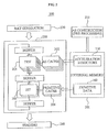
- FIG. 1 illustrates an image processing apparatus 100 according to example embodiments.
- the image processing apparatus 100 may determine a primitive that intersects a ray, and a hit point that is an intersecting point, based on primitive data of an acceleration structure.
- the image processing apparatus 100 may include a first calculator 110 , a determination unit 120 , and a second calculator 130 .
- the first calculator 110 may perform a ray-plane test for determining whether a ray generated for ray tracing intersects a plane including a primitive, and a barycentric test for determining whether the ray intersects the primitive.
- the first calculator 110 may perform the ray-plane test by reading only data required for the ray-plane test.
- the first calculator 110 may perform the barycentric test by additionally reading data for the barycentric test.
- the image processing apparatus 100 may omit data fetch or read for the barycentric test.
- the determination unit 120 may determine whether the ray intersects the plane including the primitive as the ray-plane test result.
- the determination unit 120 may also determine whether the ray intersects the primitive as a result of the barycentric test.
- the second calculator 130 may calculate a hit point regarding that the ray intersects the primitive (based on the ray intersecting the primitive).
- the first calculator 130 may include a plurality of unit calculation modules 111 that may sequentially and/or simultaneously perform the ray-plane test and the barycentric test between a single ray and a single primitive.
- the plurality of unit calculation modules 111 may have a parallel topology.
- the plurality of unit calculation modules 111 may perform the ray-plane test and/or the barycentric test in parallel with each of different rays and a single primitive.
- the plurality of unit calculation modules 111 may perform the ray-plane test and/or the barycentric test in parallel with each of different primitives with respect to a single ray.
- the plurality of unit calculation modules 111 may perform the ray-plane test and/or the barycentric test in parallel with respect to each of different rays and different primitives.
- Multiplexers MUL within the single unit calculation module 111 may be used for both the ray-plane test and the barycentric test.
- a portion of the multiplexers MUL within the unit calculation module 111 may be used for both the ray-plane test and the barycentric test, whereas a portion of remaining multiplexers MUL may be used for one of the ray-plane test and the barycentric test.
- a divider DIV and multiplexers MUL within the second calculator 130 may be used for the hit point calculation.
- a size of the divider is relatively large compared to a multiplexer and thus, may use a relatively large portion of circuit manufacturing costs. According to example embodiments, a number of dividers for an intersection test may significantly decrease and thus, circuit manufacturing costs may also significantly decrease and idle resources may be reduced.
- an intersection test between a ray generated during a ray tracing process and a primitive, for example, a triangle may be conceptually divided into the following three operations.
- One operation corresponds to a ray-plane test operation for determining whether the ray intersects a plane including the primitive, another operation corresponds to a barycentric test operation for determining whether the ray intersects the primitive, and still another operation corresponds to an operation for calculating a hit point based on the ray intersecting the primitive.
- the above three operations may be sequentially or simultaneously performed. When a test of a previous operation is not passed, a subsequent test may not be performed.
- each unit module to perform an intersection test between a ray and a primitive may include all the calculation units, for example, multipliers and a divider that may perform each of the ray-plane test, the barycentric test, and the hit point calculation.
- a rate of idle resources may be high.
- the ray-plane test and the barycentric test using only multiplexers may be performed by the first calculator 110 , and the hit point calculation using multiplexers and a diver may be performed by the second calculator 130 .
- the determination unit 120 may determine whether a ray and primitive pair pass the ray-plane test.
- the first calculator 110 may perform the barycentric test with respect to the ray and primitive pair.
- the determination unit 120 may also determine whether the ray and primitive pair pass the barycentric test. When the ray and primitive pair pass the barycentric test, the second calculator 130 may perform the hit point calculation based on the ray intersecting the primitive.
- FIG. 2 illustrates a total ray tracing process 200 including the image processing apparatus 100 of FIG. 1 according to example embodiments.
- the generated acceleration structure 250 and each primitive data 260 may be stored in an external memory 201 , for example, a dynamic random access memory (DRAM).
- DRAM dynamic random access memory
- a traversal (TRV) 203 may be performed with respect to the ray regarding (based on) which leaf node within the acceleration structure is associated with respect to the ray in operation 230 .
- a portion of the acceleration structure may be fetched from an acceleration structure (AS) cache 202 and thereby be used.
- AS acceleration structure
- the image processing apparatus 100 may perform an intersection test (IST) with respect to a plurality of primitives, for example, triangles within a predetermined leaf node.
- IST intersection test
- primitive data corresponding to an intersection test target may be fetched from a primitive cache 204 and thereby be used.
- all the data of the predetermined data may not be fetched at a one time and be fetched using a plurality of operations.
- the first calculator 110 of the image processing apparatus 100 performs a ray-plane test
- only data of a portion required for the ray-plane test may be fetched in advance.
- data of a portion for the barycentric test may also be fetched.
- the image processing apparatus 100 may recursively perform the intersection test with respect to another primitive included in the same leaf node as the primitive within the acceleration structure.
- a traversal of another leaf node may be performed.
- the image processing apparatus 100 may perform the intersection test with respect to primitives within the newly traversed leaf node using the same process.
- the second calculator 130 of the image processing apparatus 100 may perform the hit point calculation.
- shading of a color value may be performed with respect to a hit point.
- FIG. 3 illustrates a diagram 300 to describe a ray-plane test performed by the first calculator 110 of the image processing apparatus 100 according to example embodiments.
- O denotes an origin of the ray
- D denotes a direction vector
- A, B, and C denote three vertices of a triangle.
- a process of obtaining a solution of Equation 1 may obtain t that is a ray parameter, and u and v that are barycentric coordinates.
- Equation 1 may be arranged to Equation 2.
- Equation 2 may be arranged to Equation 3, and t, u, and v that are solutions of Equation 1 may be obtained.
- the determination unit 120 of the image processing apparatus 100 may determine whether Equation 4 is satisfied with respect to a plane ( 1 ) 310 within a bounding box 302 of an acceleration structure.
- the plane ( 1 ) 310 may intersect a ray 301 and thus, a primitive included in the plane ( 1 ) 310 may pass the ray-plane test.
- TMIN 303 (tmin) denotes a minimum value of a ray parameter corresponding to the bounding box 302 of the acceleration structure
- TMAX 304 (tmax) denotes a maximum value of the ray parameter.
- a plane ( 2 ) 320 including the predetermined primitive may not satisfy Equation 4. In this case, the intersection test for the primitive is terminated.
- the determination unit 120 may perform the ray-plane test according to the aforementioned scheme. Only with respect to the primitive passing the ray-plane test, the first calculator 110 may perform the barycentric test. A process of the barycentric test will be further described with reference to FIG. 4 .
- FIG. 4 illustrates a diagram 400 to describe a barycentric test performed by the first calculator 110 of the image processing apparatus 100 according to example embodiments.
- the barycentric test may be performed to determine whether an intersecting point between a ray and a plane is included within a primitive, for example, a triangle, that is, to determine whether the ray intersects the primitive using barycentric coordinates (u, v) that are determined according to Equation 3.
- Equation 5 u ⁇ 0 [Equation 5] v ⁇ 0 [Equation 6] ( u+v ) ⁇ 1 [Equation 7]
- a triangle ( 1 ) 410 may satisfy all of Equation 5, Equation 6, and Equation 7 with respect to a ray 401 and thus, pass the barycentric test.
- a triangle ( 2 ) 420 may not satisfy at least one of Equation 5, Equation 6, and Equation 7 and thus, may not pass the barycentric test.
- the second calculator 130 of the image processing apparatus 100 may perform a hit point calculation regarding at which point within the primitive the ray intersects.
- FIG. 5 illustrates a diagram 500 to describe a hit point calculation performed by the second calculator 130 of the image processing apparatus 100 according to example embodiments.
- the second calculator 130 may determine a line parameter t and barycentric coordinates u and v by calculating an accurate hit point between a ray 501 and a triangle 510 .
- FIG. 6 illustrates a diagram to compare the image processing apparatus of FIG. 1 according to example embodiments and a conventional intersection test module 600 .
- each unit module may include a portion 610 for a ray-plane test, a portion 620 for a barycentric test, and a portion 630 for a hit point calculation.
- a plurality of unit modules may be included in the conventional intersection module 600 .
- the portion 620 and/or the portion 630 may become in an idle state and thus, resources may be wasted.
- the first calculator 110 may sequentially perform the ray-plane test and the barycentric test by integrating the portion 610 and the portion 620 , and the second calculator 130 may perform a hit point calculation.
- Cases where a process up to the hit point calculation is performed may be small and thus, a relatively small number of second calculators 130 compared to a number of unit calculation modules 111 within the first calculator 110 may be included in the image processing apparatus 100 .
- FIG. 7 illustrates an image processing method according to example embodiments.
- the first calculator 110 of the image processing apparatus 100 may read, from data of a primitive that is a triangle, plane data corresponding to plane information including the triangle.
- the first calculator 110 may perform a ray-plane test with respect to a plane.
- the ray-plane test is described above with reference to FIG. 1 and FIG. 3 and thus, further descriptions will be omitted here.
- the determination unit 120 may determine whether the primitive passes the ray-plane test.
- the first calculator 110 may read, from data of the primitive, triangle data corresponding to triangle information in operation 740 , and the first calculator 110 may perform a barycentric test in operation 750 .
- the barycentric test is described above with reference to FIG. 3 and FIG. 4 and thus, further descriptions will be omitted here.
- the second calculator 130 may calculate a hit point in operation 770 . This case corresponds to ‘return true’ operation 780 .
- the image processing method for the intersection test may be terminated.
- the intersection test may be suspended with respect to the corresponding primitive. This case corresponds to ‘return miss’ in operation 790 and the intersection test may be terminated.
- intersection test may be performed with respect to another primitive.
- the image processing method may be recorded in non-transitory computer-readable media including computer readable instructions such as a computer program to implement various operations by executing computer readable instructions to control one or more processors, which are part of a general purpose computer, a computing device, a computer system, or a network of devices.
- the media may also have recorded thereon, alone or in combination with the computer readable instructions, data files, data structures, and the like.
- the computer readable instructions recorded on the media may be those specially designed and constructed for the purposes of the embodiments, or they may be of the kind well-known and available to those having skill in the computer software arts.
- the computer-readable media may also be embodied in at least one application specific integrated circuit (ASIC) or Field Programmable Gate Array (FPGA), which executes (processes like a processor) computer readable instructions.
- ASIC application specific integrated circuit
- FPGA Field Programmable Gate Array
- Examples of non-transitory computer-readable media include magnetic media such as hard disks, floppy disks, and magnetic tape; optical media such as CD ROM disks and DVDs; magneto-optical media such as optical disks; and hardware devices that are specially configured to store and perform program instructions, such as read-only memory (ROM), random access memory (RAM), flash memory, and the like.
- Examples of computer readable instructions include both machine code, such as produced by a compiler, and files containing higher level code that may be executed by the computer using an interpreter.
- the described hardware devices may be configured to act as one or more software modules in order to perform the operations of the above-described embodiments, or vice versa.
- Another example of media may also be a distributed network, so that the computer readable instructions are stored and executed in a distributed fashion.
Abstract
Description
O+t·D=A+u·(B−A)+v·(C−A), [Equation 1]
tmin≦t≦tmax [Equation 4]
u≧0 [Equation 5]
v≧0 [Equation 6]
(u+v)≦1 [Equation 7]
Claims (14)
Applications Claiming Priority (2)
| Application Number | Priority Date | Filing Date | Title |
|---|---|---|---|
| KR10-2010-0093642 | 2010-09-28 | ||
| KR1020100093642A KR101705072B1 (en) | 2010-09-28 | 2010-09-28 | Image processing apparatus and method |
Publications (2)
| Publication Number | Publication Date |
|---|---|
| US20120075287A1 US20120075287A1 (en) | 2012-03-29 |
| US8963920B2 true US8963920B2 (en) | 2015-02-24 |
Family
ID=45870175
Family Applications (1)
| Application Number | Title | Priority Date | Filing Date |
|---|---|---|---|
| US13/067,515 Active 2032-02-08 US8963920B2 (en) | 2010-09-28 | 2011-06-06 | Image processing apparatus and method |
Country Status (2)
| Country | Link |
|---|---|
| US (1) | US8963920B2 (en) |
| KR (1) | KR101705072B1 (en) |
Cited By (1)
| Publication number | Priority date | Publication date | Assignee | Title |
|---|---|---|---|---|
| US20150228110A1 (en) * | 2014-02-10 | 2015-08-13 | Pixar | Volume rendering using adaptive buckets |
Families Citing this family (7)
| Publication number | Priority date | Publication date | Assignee | Title |
|---|---|---|---|---|
| KR102072515B1 (en) | 2012-10-16 | 2020-02-03 | 삼성전자주식회사 | Apparatus and method for image processing |
| WO2015023106A1 (en) * | 2013-08-12 | 2015-02-19 | Samsung Electronics Co., Ltd. | Apparatus and method for processing image |
| KR102365112B1 (en) | 2015-03-25 | 2022-02-18 | 삼성전자주식회사 | Ray tracing apparatus and method |
| KR102467031B1 (en) * | 2015-08-31 | 2022-11-14 | 삼성전자주식회사 | Method for generating and traverse acceleration structure |
| US10332303B2 (en) | 2016-04-26 | 2019-06-25 | Imagination Technologies Limited | Dedicated ray memory for ray tracing in graphics systems |
| US10706609B1 (en) * | 2018-12-13 | 2020-07-07 | Advanced Micro Devices, Inc. | Efficient data path for ray triangle intersection |
| US11450057B2 (en) * | 2020-06-15 | 2022-09-20 | Nvidia Corporation | Hardware acceleration for ray tracing primitives that share vertices |
Citations (11)
| Publication number | Priority date | Publication date | Assignee | Title |
|---|---|---|---|---|
| US5933146A (en) * | 1994-12-01 | 1999-08-03 | Advanced Rendering Technology Limited | Method of and apparatus for constructing an image of a notional scene by a process of ray tracing |
| US7187390B2 (en) * | 2002-12-06 | 2007-03-06 | Riken | Method and program for determing intersection point of triangle with line segment |
| US7289118B2 (en) * | 2002-08-26 | 2007-10-30 | Universität des Saarlandes | Method and device for creating a two-dimensional representation of a three-dimensional structure |
| KR20080052328A (en) | 2006-12-05 | 2008-06-11 | 한국전자통신연구원 | Apparatus and method of ray-triangle collision detection for ray-tracing |
| KR20090065353A (en) | 2007-12-17 | 2009-06-22 | 한국전자통신연구원 | Ray tracing device based on pixel processing element and method thereof |
| US20090167763A1 (en) * | 2000-06-19 | 2009-07-02 | Carsten Waechter | Quasi-monte carlo light transport simulation by efficient ray tracing |
| US20090256845A1 (en) * | 2000-06-19 | 2009-10-15 | Igor Sevastianov | Accelerated ray tracing |
| US20090262132A1 (en) * | 2006-09-19 | 2009-10-22 | Caustic Graphics, Inc. | Architectures for parallelized intersection testing and shading for ray-tracing rendering |
| US20100053162A1 (en) * | 2000-06-19 | 2010-03-04 | Holger Dammertz | Accelerated ray tracing using shallow bounding volume hierarchies |
| US20100073370A1 (en) * | 2008-09-22 | 2010-03-25 | Caustic Graphics, Inc. | Systems and methods for a ray tracing shader api |
| US20110069067A1 (en) * | 2009-09-21 | 2011-03-24 | Caustic Graphics, Inc. | Systems and methods for self-intersection avoidance in ray tracing |
Family Cites Families (2)
| Publication number | Priority date | Publication date | Assignee | Title |
|---|---|---|---|---|
| JPH06274648A (en) * | 1993-03-22 | 1994-09-30 | N T T Data Tsushin Kk | Image generator |
| JP3931691B2 (en) * | 2002-03-07 | 2007-06-20 | 株式会社デンソー | Image generating apparatus and program |
-
2010
- 2010-09-28 KR KR1020100093642A patent/KR101705072B1/en active IP Right Grant
-
2011
- 2011-06-06 US US13/067,515 patent/US8963920B2/en active Active
Patent Citations (13)
| Publication number | Priority date | Publication date | Assignee | Title |
|---|---|---|---|---|
| US5933146A (en) * | 1994-12-01 | 1999-08-03 | Advanced Rendering Technology Limited | Method of and apparatus for constructing an image of a notional scene by a process of ray tracing |
| US20090167763A1 (en) * | 2000-06-19 | 2009-07-02 | Carsten Waechter | Quasi-monte carlo light transport simulation by efficient ray tracing |
| US20090256845A1 (en) * | 2000-06-19 | 2009-10-15 | Igor Sevastianov | Accelerated ray tracing |
| US20100053162A1 (en) * | 2000-06-19 | 2010-03-04 | Holger Dammertz | Accelerated ray tracing using shallow bounding volume hierarchies |
| US7289118B2 (en) * | 2002-08-26 | 2007-10-30 | Universität des Saarlandes | Method and device for creating a two-dimensional representation of a three-dimensional structure |
| US7187390B2 (en) * | 2002-12-06 | 2007-03-06 | Riken | Method and program for determing intersection point of triangle with line segment |
| US20110050698A1 (en) * | 2006-09-19 | 2011-03-03 | Caustic Graphics, Inc. | Architectures for parallelized intersection testing and shading for ray-tracing rendering |
| US20120249553A1 (en) * | 2006-09-19 | 2012-10-04 | Caustic Graphics, Inc. | Architectures for concurrent graphics processing operations |
| US20090262132A1 (en) * | 2006-09-19 | 2009-10-22 | Caustic Graphics, Inc. | Architectures for parallelized intersection testing and shading for ray-tracing rendering |
| KR20080052328A (en) | 2006-12-05 | 2008-06-11 | 한국전자통신연구원 | Apparatus and method of ray-triangle collision detection for ray-tracing |
| KR20090065353A (en) | 2007-12-17 | 2009-06-22 | 한국전자통신연구원 | Ray tracing device based on pixel processing element and method thereof |
| US20100073370A1 (en) * | 2008-09-22 | 2010-03-25 | Caustic Graphics, Inc. | Systems and methods for a ray tracing shader api |
| US20110069067A1 (en) * | 2009-09-21 | 2011-03-24 | Caustic Graphics, Inc. | Systems and methods for self-intersection avoidance in ray tracing |
Non-Patent Citations (1)
| Title |
|---|
| Kensler, A.; Optimizing Ray-Triangle Intersection via Automated Search; 2006; Interactive Ray Tracing 2006, IEEE Symposium on; pp. 33-38. * |
Cited By (2)
| Publication number | Priority date | Publication date | Assignee | Title |
|---|---|---|---|---|
| US20150228110A1 (en) * | 2014-02-10 | 2015-08-13 | Pixar | Volume rendering using adaptive buckets |
| US9842424B2 (en) * | 2014-02-10 | 2017-12-12 | Pixar | Volume rendering using adaptive buckets |
Also Published As
| Publication number | Publication date |
|---|---|
| KR20120032159A (en) | 2012-04-05 |
| KR101705072B1 (en) | 2017-02-09 |
| US20120075287A1 (en) | 2012-03-29 |
Similar Documents
| Publication | Publication Date | Title |
|---|---|---|
| US8963920B2 (en) | Image processing apparatus and method | |
| US9576389B2 (en) | Method and apparatus for generating acceleration structure in ray tracing system | |
| US7348975B2 (en) | Applications of interval arithmetic for reduction of number of computations in ray tracing problems | |
| US11069124B2 (en) | Systems and methods for reducing rendering latency | |
| US11138782B2 (en) | Systems and methods for rendering optical distortion effects | |
| US8390618B2 (en) | Technique for improving ray tracing performance | |
| KR101705581B1 (en) | Data processing apparatus and method | |
| US9355491B2 (en) | Ray tracing apparatus and method | |
| US11308683B2 (en) | Intersection testing in a ray tracing system using ray bundle vectors | |
| US20190318528A1 (en) | Computer-Graphics Based on Hierarchical Ray Casting | |
| US20190318529A1 (en) | Systems and Methods for Rendering Foveated Effects | |
| US20160314611A1 (en) | Ray tracing apparatus and method | |
| US9390545B2 (en) | Apparatus and method for traversing hierarchical acceleration structure | |
| US20150235410A1 (en) | Image processing apparatus and method | |
| US20130207967A1 (en) | Image processing apparatus and method | |
| KR20110032366A (en) | Image processing apparatus and method | |
| US10026214B2 (en) | Ray tracing apparatus and method | |
| US10115224B2 (en) | Method and apparatus generating acceleration structure | |
| EP2827302B1 (en) | Image processing apparatus and method | |
| WO2007081303A1 (en) | Applications of interval arithmetic for reduction of number of computations in ray tracing problems | |
| US10339694B2 (en) | Ray tracing apparatus and method | |
| WO2023169002A1 (en) | Soft rasterization method and apparatus, device, medium, and program product | |
| US11295509B2 (en) | Intersection testing in a ray tracing system using multiple ray bundle intersection tests | |
| US11861785B2 (en) | Generation of tight world space bounding regions | |
| EP3929877A1 (en) | Hierarchical acceleration structures for use in ray tracing systems |
Legal Events
| Date | Code | Title | Description |
|---|---|---|---|
| AS | Assignment |
Owner name: SAMSUNG ELECTRONICS CO., LTD., KOREA, REPUBLIC OF Free format text: ASSIGNMENT OF ASSIGNORS INTEREST;ASSIGNORS:PARK, CHAN MIN;HA, TACK DON;PARK, JEONG SOO;AND OTHERS;SIGNING DATES FROM 20110512 TO 20110602;REEL/FRAME:026476/0058 Owner name: INDUSTRY-ACADEMIC COOPERATION FOUNDATION, YONSEI U Free format text: ASSIGNMENT OF ASSIGNORS INTEREST;ASSIGNORS:PARK, CHAN MIN;HA, TACK DON;PARK, JEONG SOO;AND OTHERS;SIGNING DATES FROM 20110512 TO 20110602;REEL/FRAME:026476/0058 |
|
| AS | Assignment |
Owner name: INDUSTRY-ACADEMIC COOPERATION FOUNDATION,YONSEI UN Free format text: RECORD TO CORRECT 2ND INVENTOR'S NAME TO SPECIFY TACK DON HAN PREVIOUSLY RECORDED ON REEL 026476 FRAME 0058;ASSIGNORS:PARK, CHAN MIN;HAN, TACK DON;PARK, JEONG SOO;AND OTHERS;SIGNING DATES FROM 20110512 TO 20110602;REEL/FRAME:026787/0868 Owner name: SAMSUNG ELECTRONICS CO., LTD., KOREA, REPUBLIC OF Free format text: RECORD TO CORRECT 2ND INVENTOR'S NAME TO SPECIFY TACK DON HAN PREVIOUSLY RECORDED ON REEL 026476 FRAME 0058;ASSIGNORS:PARK, CHAN MIN;HAN, TACK DON;PARK, JEONG SOO;AND OTHERS;SIGNING DATES FROM 20110512 TO 20110602;REEL/FRAME:026787/0868 |
|
| FEPP | Fee payment procedure |
Free format text: PAYOR NUMBER ASSIGNED (ORIGINAL EVENT CODE: ASPN); ENTITY STATUS OF PATENT OWNER: LARGE ENTITY |
|
| STCF | Information on status: patent grant |
Free format text: PATENTED CASE |
|
| MAFP | Maintenance fee payment |
Free format text: PAYMENT OF MAINTENANCE FEE, 4TH YEAR, LARGE ENTITY (ORIGINAL EVENT CODE: M1551) Year of fee payment: 4 |
|
| MAFP | Maintenance fee payment |
Free format text: PAYMENT OF MAINTENANCE FEE, 8TH YEAR, LARGE ENTITY (ORIGINAL EVENT CODE: M1552); ENTITY STATUS OF PATENT OWNER: LARGE ENTITY Year of fee payment: 8 |