US8945699B2 - Sheet, an article, and a method of making a sheet - Google Patents
Sheet, an article, and a method of making a sheet Download PDFInfo
- Publication number
- US8945699B2 US8945699B2 US12/263,719 US26371908A US8945699B2 US 8945699 B2 US8945699 B2 US 8945699B2 US 26371908 A US26371908 A US 26371908A US 8945699 B2 US8945699 B2 US 8945699B2
- Authority
- US
- United States
- Prior art keywords
- sheet
- equal
- protrusions
- diameter
- less
- Prior art date
- Legal status (The legal status is an assumption and is not a legal conclusion. Google has not performed a legal analysis and makes no representation as to the accuracy of the status listed.)
- Active, expires
Links
Images


Classifications
-
- E—FIXED CONSTRUCTIONS
- E04—BUILDING
- E04C—STRUCTURAL ELEMENTS; BUILDING MATERIALS
- E04C2/00—Building elements of relatively thin form for the construction of parts of buildings, e.g. sheet materials, slabs, or panels
- E04C2/02—Building elements of relatively thin form for the construction of parts of buildings, e.g. sheet materials, slabs, or panels characterised by specified materials
- E04C2/10—Building elements of relatively thin form for the construction of parts of buildings, e.g. sheet materials, slabs, or panels characterised by specified materials of wood, fibres, chips, vegetable stems, or the like; of plastics; of foamed products
- E04C2/20—Building elements of relatively thin form for the construction of parts of buildings, e.g. sheet materials, slabs, or panels characterised by specified materials of wood, fibres, chips, vegetable stems, or the like; of plastics; of foamed products of plastics
-
- B29C47/0038—
-
- B—PERFORMING OPERATIONS; TRANSPORTING
- B29—WORKING OF PLASTICS; WORKING OF SUBSTANCES IN A PLASTIC STATE IN GENERAL
- B29C—SHAPING OR JOINING OF PLASTICS; SHAPING OF MATERIAL IN A PLASTIC STATE, NOT OTHERWISE PROVIDED FOR; AFTER-TREATMENT OF THE SHAPED PRODUCTS, e.g. REPAIRING
- B29C48/00—Extrusion moulding, i.e. expressing the moulding material through a die or nozzle which imparts the desired form; Apparatus therefor
- B29C48/001—Combinations of extrusion moulding with other shaping operations
-
- B—PERFORMING OPERATIONS; TRANSPORTING
- B29—WORKING OF PLASTICS; WORKING OF SUBSTANCES IN A PLASTIC STATE IN GENERAL
- B29C—SHAPING OR JOINING OF PLASTICS; SHAPING OF MATERIAL IN A PLASTIC STATE, NOT OTHERWISE PROVIDED FOR; AFTER-TREATMENT OF THE SHAPED PRODUCTS, e.g. REPAIRING
- B29C48/00—Extrusion moulding, i.e. expressing the moulding material through a die or nozzle which imparts the desired form; Apparatus therefor
- B29C48/03—Extrusion moulding, i.e. expressing the moulding material through a die or nozzle which imparts the desired form; Apparatus therefor characterised by the shape of the extruded material at extrusion
- B29C48/09—Articles with cross-sections having partially or fully enclosed cavities, e.g. pipes or channels
-
- B—PERFORMING OPERATIONS; TRANSPORTING
- B29—WORKING OF PLASTICS; WORKING OF SUBSTANCES IN A PLASTIC STATE IN GENERAL
- B29C—SHAPING OR JOINING OF PLASTICS; SHAPING OF MATERIAL IN A PLASTIC STATE, NOT OTHERWISE PROVIDED FOR; AFTER-TREATMENT OF THE SHAPED PRODUCTS, e.g. REPAIRING
- B29C48/00—Extrusion moulding, i.e. expressing the moulding material through a die or nozzle which imparts the desired form; Apparatus therefor
- B29C48/03—Extrusion moulding, i.e. expressing the moulding material through a die or nozzle which imparts the desired form; Apparatus therefor characterised by the shape of the extruded material at extrusion
- B29C48/12—Articles with an irregular circumference when viewed in cross-section, e.g. window profiles
-
- E—FIXED CONSTRUCTIONS
- E04—BUILDING
- E04C—STRUCTURAL ELEMENTS; BUILDING MATERIALS
- E04C2/00—Building elements of relatively thin form for the construction of parts of buildings, e.g. sheet materials, slabs, or panels
- E04C2/30—Building elements of relatively thin form for the construction of parts of buildings, e.g. sheet materials, slabs, or panels characterised by the shape or structure
- E04C2/32—Building elements of relatively thin form for the construction of parts of buildings, e.g. sheet materials, slabs, or panels characterised by the shape or structure formed of corrugated or otherwise indented sheet-like material; composed of such layers with or without layers of flat sheet-like material
- E04C2/324—Building elements of relatively thin form for the construction of parts of buildings, e.g. sheet materials, slabs, or panels characterised by the shape or structure formed of corrugated or otherwise indented sheet-like material; composed of such layers with or without layers of flat sheet-like material with incisions or reliefs in the surface
-
- E—FIXED CONSTRUCTIONS
- E04—BUILDING
- E04D—ROOF COVERINGS; SKY-LIGHTS; GUTTERS; ROOF-WORKING TOOLS
- E04D3/00—Roof covering by making use of flat or curved slabs or stiff sheets
- E04D3/24—Roof covering by making use of flat or curved slabs or stiff sheets with special cross-section, e.g. with corrugations on both sides, with ribs, flanges, or the like
- E04D3/28—Roof covering by making use of flat or curved slabs or stiff sheets with special cross-section, e.g. with corrugations on both sides, with ribs, flanges, or the like of glass or other translucent material
-
- B29C47/0021—
-
- B29C47/02—
-
- B29C47/903—
-
- B—PERFORMING OPERATIONS; TRANSPORTING
- B29—WORKING OF PLASTICS; WORKING OF SUBSTANCES IN A PLASTIC STATE IN GENERAL
- B29C—SHAPING OR JOINING OF PLASTICS; SHAPING OF MATERIAL IN A PLASTIC STATE, NOT OTHERWISE PROVIDED FOR; AFTER-TREATMENT OF THE SHAPED PRODUCTS, e.g. REPAIRING
- B29C48/00—Extrusion moulding, i.e. expressing the moulding material through a die or nozzle which imparts the desired form; Apparatus therefor
- B29C48/03—Extrusion moulding, i.e. expressing the moulding material through a die or nozzle which imparts the desired form; Apparatus therefor characterised by the shape of the extruded material at extrusion
- B29C48/07—Flat, e.g. panels
- B29C48/08—Flat, e.g. panels flexible, e.g. films
-
- B—PERFORMING OPERATIONS; TRANSPORTING
- B29—WORKING OF PLASTICS; WORKING OF SUBSTANCES IN A PLASTIC STATE IN GENERAL
- B29C—SHAPING OR JOINING OF PLASTICS; SHAPING OF MATERIAL IN A PLASTIC STATE, NOT OTHERWISE PROVIDED FOR; AFTER-TREATMENT OF THE SHAPED PRODUCTS, e.g. REPAIRING
- B29C48/00—Extrusion moulding, i.e. expressing the moulding material through a die or nozzle which imparts the desired form; Apparatus therefor
- B29C48/15—Extrusion moulding, i.e. expressing the moulding material through a die or nozzle which imparts the desired form; Apparatus therefor incorporating preformed parts or layers, e.g. extrusion moulding around inserts
-
- B—PERFORMING OPERATIONS; TRANSPORTING
- B29—WORKING OF PLASTICS; WORKING OF SUBSTANCES IN A PLASTIC STATE IN GENERAL
- B29C—SHAPING OR JOINING OF PLASTICS; SHAPING OF MATERIAL IN A PLASTIC STATE, NOT OTHERWISE PROVIDED FOR; AFTER-TREATMENT OF THE SHAPED PRODUCTS, e.g. REPAIRING
- B29C48/00—Extrusion moulding, i.e. expressing the moulding material through a die or nozzle which imparts the desired form; Apparatus therefor
- B29C48/25—Component parts, details or accessories; Auxiliary operations
- B29C48/88—Thermal treatment of the stream of extruded material, e.g. cooling
- B29C48/90—Thermal treatment of the stream of extruded material, e.g. cooling with calibration or sizing, i.e. combined with fixing or setting of the final dimensions of the extruded article
- B29C48/901—Thermal treatment of the stream of extruded material, e.g. cooling with calibration or sizing, i.e. combined with fixing or setting of the final dimensions of the extruded article of hollow bodies
- B29C48/903—Thermal treatment of the stream of extruded material, e.g. cooling with calibration or sizing, i.e. combined with fixing or setting of the final dimensions of the extruded article of hollow bodies externally
-
- B—PERFORMING OPERATIONS; TRANSPORTING
- B29—WORKING OF PLASTICS; WORKING OF SUBSTANCES IN A PLASTIC STATE IN GENERAL
- B29C—SHAPING OR JOINING OF PLASTICS; SHAPING OF MATERIAL IN A PLASTIC STATE, NOT OTHERWISE PROVIDED FOR; AFTER-TREATMENT OF THE SHAPED PRODUCTS, e.g. REPAIRING
- B29C48/00—Extrusion moulding, i.e. expressing the moulding material through a die or nozzle which imparts the desired form; Apparatus therefor
- B29C48/25—Component parts, details or accessories; Auxiliary operations
- B29C48/88—Thermal treatment of the stream of extruded material, e.g. cooling
- B29C48/90—Thermal treatment of the stream of extruded material, e.g. cooling with calibration or sizing, i.e. combined with fixing or setting of the final dimensions of the extruded article
- B29C48/905—Thermal treatment of the stream of extruded material, e.g. cooling with calibration or sizing, i.e. combined with fixing or setting of the final dimensions of the extruded article using wet calibration, i.e. in a quenching tank
-
- B—PERFORMING OPERATIONS; TRANSPORTING
- B29—WORKING OF PLASTICS; WORKING OF SUBSTANCES IN A PLASTIC STATE IN GENERAL
- B29C—SHAPING OR JOINING OF PLASTICS; SHAPING OF MATERIAL IN A PLASTIC STATE, NOT OTHERWISE PROVIDED FOR; AFTER-TREATMENT OF THE SHAPED PRODUCTS, e.g. REPAIRING
- B29C48/00—Extrusion moulding, i.e. expressing the moulding material through a die or nozzle which imparts the desired form; Apparatus therefor
- B29C48/25—Component parts, details or accessories; Auxiliary operations
- B29C48/88—Thermal treatment of the stream of extruded material, e.g. cooling
- B29C48/919—Thermal treatment of the stream of extruded material, e.g. cooling using a bath, e.g. extruding into an open bath to coagulate or cool the material
-
- Y—GENERAL TAGGING OF NEW TECHNOLOGICAL DEVELOPMENTS; GENERAL TAGGING OF CROSS-SECTIONAL TECHNOLOGIES SPANNING OVER SEVERAL SECTIONS OF THE IPC; TECHNICAL SUBJECTS COVERED BY FORMER USPC CROSS-REFERENCE ART COLLECTIONS [XRACs] AND DIGESTS
- Y10—TECHNICAL SUBJECTS COVERED BY FORMER USPC
- Y10T—TECHNICAL SUBJECTS COVERED BY FORMER US CLASSIFICATION
- Y10T428/00—Stock material or miscellaneous articles
- Y10T428/24—Structurally defined web or sheet [e.g., overall dimension, etc.]
- Y10T428/24174—Structurally defined web or sheet [e.g., overall dimension, etc.] including sheet or component perpendicular to plane of web or sheet
-
- Y—GENERAL TAGGING OF NEW TECHNOLOGICAL DEVELOPMENTS; GENERAL TAGGING OF CROSS-SECTIONAL TECHNOLOGIES SPANNING OVER SEVERAL SECTIONS OF THE IPC; TECHNICAL SUBJECTS COVERED BY FORMER USPC CROSS-REFERENCE ART COLLECTIONS [XRACs] AND DIGESTS
- Y10—TECHNICAL SUBJECTS COVERED BY FORMER USPC
- Y10T—TECHNICAL SUBJECTS COVERED BY FORMER US CLASSIFICATION
- Y10T428/00—Stock material or miscellaneous articles
- Y10T428/24—Structurally defined web or sheet [e.g., overall dimension, etc.]
- Y10T428/24479—Structurally defined web or sheet [e.g., overall dimension, etc.] including variation in thickness
-
- Y—GENERAL TAGGING OF NEW TECHNOLOGICAL DEVELOPMENTS; GENERAL TAGGING OF CROSS-SECTIONAL TECHNOLOGIES SPANNING OVER SEVERAL SECTIONS OF THE IPC; TECHNICAL SUBJECTS COVERED BY FORMER USPC CROSS-REFERENCE ART COLLECTIONS [XRACs] AND DIGESTS
- Y10—TECHNICAL SUBJECTS COVERED BY FORMER USPC
- Y10T—TECHNICAL SUBJECTS COVERED BY FORMER US CLASSIFICATION
- Y10T428/00—Stock material or miscellaneous articles
- Y10T428/24—Structurally defined web or sheet [e.g., overall dimension, etc.]
- Y10T428/24628—Nonplanar uniform thickness material
- Y10T428/24669—Aligned or parallel nonplanarities
-
- Y—GENERAL TAGGING OF NEW TECHNOLOGICAL DEVELOPMENTS; GENERAL TAGGING OF CROSS-SECTIONAL TECHNOLOGIES SPANNING OVER SEVERAL SECTIONS OF THE IPC; TECHNICAL SUBJECTS COVERED BY FORMER USPC CROSS-REFERENCE ART COLLECTIONS [XRACs] AND DIGESTS
- Y10—TECHNICAL SUBJECTS COVERED BY FORMER USPC
- Y10T—TECHNICAL SUBJECTS COVERED BY FORMER US CLASSIFICATION
- Y10T428/00—Stock material or miscellaneous articles
- Y10T428/24—Structurally defined web or sheet [e.g., overall dimension, etc.]
- Y10T428/24942—Structurally defined web or sheet [e.g., overall dimension, etc.] including components having same physical characteristic in differing degree
Definitions
- Thin, transparent polymeric sheets e.g., a polycarbonate sheet with a thickness of about 1-3 mm
- Thin, transparent polymeric sheets have similar light transmission values to that of glass.
- the lack of stiffness of a flat thin sheet reduces its overall practical use in applications subjected to a wind load stress since a thin sheet does not withstand an expected wind load.
- a sheet that comprises protrusions comprising a first portion extending from a base by a second portion.
- a second portion diameter is less than a first portion diameter.
- a sheet that comprises a first portion and a second portion extending from a symmetry plane, where the protrusions repeat across a length of the sheet along the symmetry plane.
- the first portion has a first portion diameter and the second portion has a second portion diameter.
- the second portion diameter is less than the first portion diameter.
- a sheet that comprises a plurality of cavities across a width of the sheet. Each cavity extends the length of the sheet and the cavity has an opening diameter that is smaller than a body diameter.
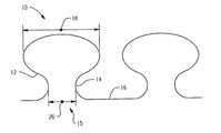
- FIG. 1 is a front profile view of an embodiment of the protrusions.
- FIG. 2 is a front profile view of an embodiment of the protrusions.
- FIG. 3 is a front profile view of a corrugation in a sheet.
- FIG. 4 is a front profile view of an embodiment of the protrusions.
- FIG. 5 is a front profile view of an embodiment of the protrusions.
- FIG. 6 is a front profile view of an embodiment of the protrusions.
- FIG. 7 is a front profile view of an embodiment of the protrusions.
- FIG. 8 is a front profile view of an embodiment of the protrusions.
- FIG. 9 is a front profile view of the embodiment of FIG. 2 .
- FIG. 10 is a side view of an embodiment of a sheet manufacturing line.
- FIG. 11 is a front profile view of a corrugation in a sheet.
- the sheet comprises a surface(s).
- the surface(s) comprises protrusions.
- the protrusions act as structural support members when stress (e.g., air or wind) is applied to the sheet.
- the protrusions assist in decreasing the amount of deflection of the sheet when high stress (e.g., hurricane force wind) is applied.
- the protrusions can have a larger diameter portion attached to a base (e.g., a sheet) by a smaller diameter portion, which when placed under stress, increase the stiffness of the sheet.
- the protrusion can comprise a pattern that can be repeated across the width of the sheet.
- the external load e.g., wind; in extreme cases, hurricane force wind
- the external load causes a minor decrease (e.g., less than or equal to 10%) in the diameter of the larger diameter portion, while simultaneously causing a minor increase in the diameter of the smaller diameter portion.
- the protrusions remain substantially the same shape as the external load is applied. However, the protrusions become stiff and act as a structural reinforcing member as the load is applied. This allows greater loads to be handled by the same thickness of material sheets and/or for the same load to be handled by thinner sheets or sheets of a different material.
- the sheet is less stiff (i.e., less structural support members are present in the overall sheet), with the protrusions becoming stiffer as the external load is applied. Essentially, due to the design of the protrusions, the stress is applied more evenly about the protrusion, without substantially changing the shape of the protrusion.
- a sheet comprises protrusions comprising a first portion extending from a base by a second portion.
- the second portion comprises a second portion diameter that is less than a first portion diameter.
- a sheet comprises protrusions comprising a first portion and a second portion extending from a symmetry plane, where the protrusions repeat across a length of the sheet along the symmetry plane.
- the first portion comprises a first portion diameter and the second portion comprises a second portion diameter.
- the second portion diameter is less than the first portion diameter.
- a method of making a sheet comprises extruding a sheet comprising a surface and disposing protrusions on the surface where the protrusions comprise a first portion connected to a base by a second portion.
- the second portion comprises a second portion diameter that is less than a first portion diameter.
- the embodiments can further comprise where the second portion diameter is less than or equal to 90% of the first portion diameter, specifically less than or equal to 80% of the first portion diameter, more specifically less than or equal to 70% of the first portion diameter.
- the embodiments can also further comprise wherein the second portion diameter is 25% to 75% of the first portion diameter, specifically 25% to 55% of the first portion diameter.
- the embodiments can also comprise where the change in diameter of the first diameter portion of a stressed protrusion is less than or equal to 10% of the first portion diameter of a non-stressed protrusion, more specifically less than equal to 5% of the first portion diameter of a non-stressed protrusion.
- the sheet comprises polycarbonate.
- the embodiments can further comprise an article, where the article is selected from the group consisting of a storm panel, roofing, or a wall panel.
- the embodiments can also comprise a sheet further comprising a unit cell comprising a periodic symmetry plane, where the unit cell repeats across a length of the sheet along a periodic symmetry plane.
- the embodiments can also further comprise the sheet having a mid-sheet deflection of less than or equal to 35 mm at a thickness of 1.8 mm, length of 1890 mm, and width of 1444 mm, specifically less than or equal to 30 mm.
- the embodiments can also comprise the sheet having a mid-sheet deflection of less than or equal to 45 mm at a thickness of 1.3 mm, length of 1890 mm, and width of 1444 mm specifically less than or equal to 40 mm.
- the embodiments can further comprise the sheet having stiffness greater than or equal to 70,000 N/m at a thickness of 1.8 mm, length of 1890 mm, and width of 1444 mm specifically greater than or equal to 85,000 N/m.
- the embodiments can still further comprise the sheet having a stiffness of greater than or equal to 62,000 N/m at a thickness of 1.3 mm, length of 1890 mm, and width of 1444 mm, specifically greater than or equal to 69,000 N/m.
- thermoplastics include polyalkylenes (e.g., polyethylene, polypropylene, polyalkylene terephthalates (such as polyethylene terephthalate, polybutylene terephthalate)), polycarbonates, acrylics, polyacetals, styrenes (e.g., impact-modified polystyrene, acrylonitrile-butadiene-styrene, styrene-acrylonitrile), poly(meth)acrylates (e.g., polybutyl acrylate, polymethyl methacrylate), polyetherimide, polyurethanes, polyphenylene sulfides, polyvinyl chlorides, polysulfones, polyetherketones, polyether etherketone
- thermoplastic blends comprise acrylonitrile-butadiene-styrene/nylon, polycarbonate/acrylonitrile-butadiene-styrene, acrylonitrile butadiene styrene/polyvinyl chloride, polyphenylene ether/polystyrene, polyphenylene ether/nylon, polysulfone/acrylonitrile-butadiene-styrene, polycarbonate/thermoplastic urethane, polycarbonate/polyethylene terephthalate, polycarbonate/polybutylene terephthalate, thermoplastic elastomer alloys, nylon/elastomers, polyester/elastomers, polyethylene terephthalate/polybutylene terephthalate, acetal/elastomer, styrene-maleic anhydride/acrylonitrile-butadiene-styrene, polyether etherketone/polyethersulfone, poly
- thermoplastic copolymers comprise poly(ethylene terephthalate copolymers (APET, PETG), cyclic olefin copolymers, acrylic olefin copolymers, and so forth, as well as combinations comprising at least one of the foregoing.
- a polycarbonate material is employed, such as those designated by the trade name Lexan®, which are commercially available from SABIC Innovative Plastics.
- Thermoplastic polycarbonate resin that can be employed in producing the plastic sheet includes, without limitation, aromatic polycarbonates, copolymers of an aromatic polycarbonate such as polyester carbonate copolymer, blends thereof, and blends thereof with other polymers depending on the end use application.
- the thermoplastic polycarbonate resin is an aromatic homo-polycarbonate resin such as the polycarbonate resins described in U.S. Pat. No. 4,351,920 to Ariga et al.
- some possible polycarbonates can be prepared by reacting a dihedral phenol with a carbonate precursor, such as phosgene, a haloformate, or a carbonate ester.
- a carbonate precursor such as phosgene, a haloformate, or a carbonate ester.
- carbonate polymers comprise recurring structural units of the Formula (I)
- the polycarbonate can have an intrinsic viscosity (as measured in methylene chloride at 25° C.) of about 0.30 to about 1.00 deciliter/gram (dL/g).
- the dihydric phenols employed to provide such polycarbonates can be mononuclear or polynuclear aromatic compounds, containing as functional groups two hydroxy radicals, each of which is attached directly to a carbon atom of an aromatic nucleus.
- Possible dihydric phenols include, for example, 2,2-bis(4-hydroxyphenyl)propane (bisphenol A), hydroquinone, resorcinol, 2,2-bis(4-hydroxyphenyl)pentane, 2,4′-(dihydroxydiphenyl)methane, bis(2-hydroxyphenyl)methane, bis(4-hydroxyphenyl)methane, bis(4-hydroxy-5-nitrophenyl)methane, 1,1-bis(4-hydroxyphenyl)ethane, 3,3-bis(4-hydroxyphenyl)pentane, 2,2-dihydroxydiphenyl, 2,6-dihydroxynaphthalene, bis(4-hydroxydiphenyl)sulfone, bis(3,5-diethyl-4-hydroxyphenyl)sulfone, 2,2-bis(3,5-dimethyl-4-hydroxyphenyl)propane, 2,4′-dihydroxydiphenyl sulfone, 5′-chloro-2,
- the polycarbonate resins can be manufactured by known processes, such as, for example and as mentioned above, by reacting a dihydric phenol with a carbonate precursor, such as phosgene, a haloformate, or a carbonate ester, in accordance with methods set forth in the above-cited literature and in U.S. Pat. No. 4,123,436 to Holub et al., or by transesterification processes such as are disclosed in U.S. Pat. No. 3,153,008 to Fox, as well as other processes.
- a carbonate precursor such as phosgene, a haloformate, or a carbonate ester
- the polycarbonates can be branched or linear and generally will have a weight average molecular weight (Mw) of 10,000 to 200,000 atomic mass units (AMU), specifically 20,000 to 100,000 AMU as measured by gel permeation chromatography.
- Mw weight average molecular weight
- AMU atomic mass units
- the polycarbonates disclosed herein can employ a variety of end groups to improve performance, such as bulky mono phenols, including cumyl phenol.
- Additives can be employed to modify the performance, properties, or processing of the polymeric material.
- exemplary additives comprise antioxidants, such as, organophosphites, for example, tris(nonyl-phenyl)phosphite, tris(2,4-di-t-butylphenyl)phosphite, bis(2,4-di-t-butylphenyl)pentaerythritol diphosphite or distearyl pentaerythritol diphosphite, alkylated monophenols, polyphenols and alkylated reaction products of polyphenols with dienes, such as, for example, tetrakis[methylene(3,5-di-tert-butyl-4-hydroxyhydrocinnamate)]methane, 3,5-di-tert-butyl-4-hydroxyhydrocinnamate octadecyl, 2,4-di-tert-butylphenyl phos
- a coating(s) can be disposed on any of the sheet's surfaces to improve the sheet's properties if the coating does not decrease the strength or light transmission of the panel such that the panel is non-operative.
- Exemplary coatings can comprise antifungal coatings, hydrophobic coatings, hydrophilic coatings, light dispersion coatings, anti-condensation coatings, scratch resistant coatings, and the like, as well as combinations comprising at least one of the foregoing.
- the polycarbonate sheet can be coated with a silicone or acrylate hardcoat providing abrasion resistance and solvent resistance to the sheet.
- Additives can be employed to modify the performance, properties, or processing of the plastic material.
- exemplary additives comprise antioxidants, such as, organophosphites, for example, tris(nonyl-phenyl)phosphite, tris(2,4-di-t-butylphenyl)phosphite, bis(2,4-di-t-butylphenyl)pentaerythritol diphosphite or distearyl pentaerythritol diphosphite, alkylated monophenols, polyphenols and alkylated reaction products of polyphenols with dienes, such as, for example, tetrakis[methylene(3,5-di-tert-butyl-4-hydroxyhydrocinnamate)]methane, 3,5-di-tert-butyl-4-hydroxyhydrocinnamate octadecyl, 2,4-di-tert-butylphenyl phosphi
- the specific thickness of the plastic sheet(s) is dependent upon the particular use of the sheet, e.g., the degree of structural integrity that is desired from the plastic sheet(s), as well as the particular composition of each of the plastic sheet(s).
- the plastic sheet(s) can have a thickness of about 0.10 millimeter (mm) to about 32 mm or, more specifically, about 0.5 mm to about 15 mm or, even more specifically, about 1.0 mm to about 12 mm, and still more specifically about 1.0 mm to about 6.0 mm.
- the specific length and width of the sheet is also dependent upon the particular use of the sheet.
- the plastic sheet(s) can have a length of 2438 mm and a width of 2032 mm, specifically a length of 2438 mm and a width of 1829 mm, more specifically a length of 1890 mm and a width of 1444 mm, still more specifically a length of 1524 mm and a width of 1219 mm, and yet more specifically a length of 1524 mm and width of 991 mm.
- Wind force winds are an extreme stress (i.e., wind load) for any structural glazing design (i.e., sheet).
- the wind load itself is used as a stiffening member to increase the performance of the structure.
- the design of the structure functions to use the wind exerted, thereby also increasing the load carrying capacity.
- the performance of the structure increases with increased loading.
- FIGS. 1 and 2 illustrate embodiments of a protrusion 10 .
- a first portion 12 is connected to a base 16 by a second portion 14 .
- the first portion 12 comprises a first portion diameter 18 and the second portion 14 comprises a second portion diameter 20 .
- the diameters are the major diameter (i.e., the longest diameter) for the particular portion.
- the first portion 12 is within the protrusion 10
- the second portion 14 is adjacent an opening 15 between the base 16 and the second portion 14 .
- the second portion diameter 20 is less than or equal to 90% of the first portion diameter 18 .
- the second portion diameter 20 is less than or equal to 80% of the first portion diameter 18 , specifically less than or equal to 70% of the first portion diameter 18 , more specifically less than or equal to 60% of the first diameter portion 18 ; e.g., the second portion diameter 20 can be 25% to 75% of the first portion diameter 18 , specifically the second portion diameter 20 can be 25% to 55% of the first portion diameter 18 .
- the protrusions comprise a first portion 22 and a second portion 24 with a symmetry plane 26 between the first portion 22 and the second portion 24 and a mirror symmetry plane 36 between adjacent protrusions.
- the first portion 22 comprises a first portion diameter 28 and the second portion 24 comprises a second portion diameter 30 .
- the first portion 22 and the second portion 24 can be repeated across the width of the sheet with respect to the symmetry plane 26 .
- the sheet is designed such that cavities are formed (e.g., the protrusion forms a cavity) such that an opening into the cavity (e.g., the second portion 24 ) has an opening diameter ( 22 ) that is narrower than a body diameter ( 30 ) in the body of the cavity (e.g., first portion 22 ).
- the second portion 24 can diverge to the first portion 22 .
- Various geometries are possible wherein the opening to the cavity is smaller than a point within the cavity.
- FIG. 9 illustrates the embodiment of FIG. 2 , where each protrusion 32 fills a unit cell 34 .
- the unit cell 34 repeats across the length of the sheet to fill the sheet with protrusions.
- a stress e.g., wind
- stress can be applied to the sheet in any direction.
- the stress is applied to the first portion 12 , 22 of the protrusion 10 .
- the stress is applied to the second portion 14 , 24 of the protrusion 10 .
- the stress is applied to the first portion 12 , 22 of the protrusion 10 and to the second portion 14 , 24 of the protrusion 10 .
- the first portion 12 , 22 of the protrusions deflects downward causing expansion of the first portion 12 , 22 in the direction of the first portion diameter 18 , 28 .
- the second portion 14 , 24 of the protrusions deflects upward causing contraction of the first portion 12 , 22 in the direction of the first portion diameter 18 , 28 .
- An overall change in the first portion diameter 18 , 28 of a stressed protrusion 10 as compared to a non-stressed protrusion can be less than or equal to 10%, more specifically less than or equal to 5%.
- the protrusions as shown in FIG. 3 flatten when a load is applied (e.g., see FIG. 11 ).
- the second portion diameter 20 is less than or equal to 90% of the first portion diameter 18 , specifically less than or equal to 80% of the first portion diameter 18 , more specifically less than or equal to 70% of the first portion diameter 18 , and yet more specifically less than or equal to 60% of the first diameter portion 18 ; for example, the second portion diameter 20 can be 25% to 75% of the first portion diameter 18 , specifically the second portion diameter 20 can be 25% to 55% of the first portion diameter 18 .
- the protrusions become stiff and act as structural reinforcing members to the sheet.
- stress is decreased by greater than or equal to 20%, specifically greater than or equal to 25%, more specifically, greater than or equal to 35%, still more specifically greater than or equal to 45%.
- deflection is decreased by greater than or equal to 5%, specifically greater than or equal to 10%, more specifically greater than or equal to 25%, still more specifically greater than or equal to 50%, yet more specifically greater than or equal to 60%, more specifically still greater than or equal to 75%.
- the protrusions can be shaped such that the first portion 12 of the protrusion 10 is broader than the second portion 14 .
- the protrusions can be present on a portion of a sheet.
- the protrusions can be present throughout the length of a sheet.
- the protrusions can be present on a portion of the sheet and present throughout the length and/or width of the sheet.
- the protrusions can form a pattern and can be dispersed about the sheet across the width of the sheet.
- the sheets disclosed herein can be processed via any polymer processing method, including, but not limited to extrusion or calendaring.
- a single screw extruder can be employed to extrude a polymer melt (e.g., polycarbonate, such as Lexan®, commercially available from SABIC Innovative Plastics).
- the polymer melt is fed to a profile die capable of forming an extrudate having a cross-section.
- the sheet travels through a sizing apparatus (e.g., vacuum bath comprising sizing dies) and is then cooled below its glass transition temperature (e.g., for polycarbonate, about 297° F. (147° C.)).
- the panel After the panel has cooled, it can be cut to the desired length utilizing an extrusion cutter, such as an indexing in-line saw. Once cut, the sheet can be subjected to secondary operations before packaging. Exemplary secondary operations can comprise annealing, printing, attachment of fastening members, trimming, further assembly operations, and/or any other desirable processes.
- the size of the extruder as measured by the diameter of the extruder's screw, is based upon the production rate desired and calculated from the volumetric production rate of the extruder and the cross-sectional area of the panel.
- the cooling apparatus can be sized (e.g., length) to remove heat from the extrudate in an expedious manner without imparting haze.
- the size of the extruder, cooling capacity of the cooling apparatus, and cutting operation can be capable of producing the sheet at a rate of greater than or equal to about 5 feet per minute. However, production rates of greater than about 10 feet per minute, or even greater than about 15 feet per minute can be achieved if such rates are capable of producing surface features that comprise the desired attributes.
- Coextrusion methods can also be employed for the production of the sheet. Coextrusion can be employed to supply different polymers to any portion of the sheet's geometry to improve and/or alter the performance of the sheet and/or to reduce raw material costs. In one embodiment, a coextrusion process can be employed to reduce raw material costs by supplying a less expensive polymer to non-structural sections (e.g., foamed or recycled materials). In another embodiment, a coextrusion process can be employed to apply a polymer comprising high light transmission (e.g., greater than or equal to about 80%) to the top surface and/or bottom surface.
- a coextrusion process can be employed to apply a polymer comprising high light transmission (e.g., greater than or equal to about 80%) to the top surface and/or bottom surface.
- the manufacturing line 40 comprises an extrusion process 42 and a protrusion forming process 44 .
- the extrusion process 42 comprises a primary extruder 46 to which is supplied a polymer (not shown) from a hopper/dryer 48 .
- the polymer is melted and conveyed through the extruder 48 and pushed through a profile die 50 .
- the profile die 50 comprises a design that is capable of producing a corrugated sheet 52 .
- the protruded sheet 52 is fed through a vacuum water bath 54 that is capable of sizing and cooling the corrugated sheet 52 .
- the corrugated sheet 52 continues into the protrusion forming process 44 , which comprises a hot melt coating die 56 that disposes a hot melt 62 onto the top surface of the protruded sheet 52 .
- the hot melt coating die 56 is fed from a secondary extruder 58 that converts a second polymer (not shown) into the hot melt 62 .
- the secondary extruder 58 is fed the second polymer by a second hopper/dryer 60 .
- the hot melt 62 is formed into further protrusions 64 by an embossing belt 66 .
- the sheet forming manufacturing line 40 can comprise variations of the extrusion process 42 and the protrusion forming process 44 can comprise additional operations such as coating, forming, laminating, printing, labeling, annealing, cutting, trimming, assembling, and so forth, as well as combinations comprising at least one of the foregoing.
- a method of making a sheet as disclosed herein can include various methods of forming the protrusions into a sheet, such as extruding a sheet and then using a calendaring process, cold bending method, and so forth, to form the protrusions into the sheet.
- the corrugated sheet can be extruded through a die (profiled surface extrusion) to form the desired surface features directly from the extruder.
- Other methods of forming sheets can also be employed if they are capable of attaining the desired profile.
- FEM finite element method
- Comparative Samples A and B utilize non-stress stiffening protrusions as illustrated in FIG. 3 , while Samples 1 and 2 utilize stress-stiffening protrusions as illustrated in FIG. 1 .
- the sheet thickness is varied between the samples to illustrate that lower deflection could be achieved with the sheets having the protrusions described herein with less starting material (i.e., a lower thickness and hence lower weight sheet could be used while still resulting in lower deflection compared to sheets with a higher thickness and without the protrusions described herein).
- Comparative Samples A and B flatten when a load is applied, rather than stiffen (see e.g., FIG. 11 ).
- Table 1 provides the dimensions of each sample along with the external stress load used, while Table 2 provides the results of the analysis conducted.
- the length of the samples is 1890 millimeters (mm) and the width is 1444 mm, while the thickness varies from 1.30 mm to 2.36 mm.
- the crown height, or resting height of the protrusions i.e., height before an external stress was applied), is 51 mm.
- the same load is used in each sample, 2489 Newtons per square meter (N/m 2 ). A load is applied to the sheet and deflection of the sheet is measured in Plane X, and Plane Y, and then total deflection of the sheet is measured. Total deflection is the deformation in the thickness direction.
- the inplane deflection (i.e, deflection in Plane X and Plane Y) are measured against the lateral deformation.
- the Z direction is the mid-sheet deflection, which is an important characteristic for performance requirements. If the deflection is too great, it can break the surface onto which the sheet is attached to (e.g., glass).
- Deflection in Plane X deflection evaluates pop out deformation, while deflection in Plane Y measures transverse deflection. Deflection in the middle of the sheet (deflection mid-sheet) is also measured.
- the load is applied to the protrusions.
- the Max Von Mises Stress is also measured and the Boundary Condition is constant.
- the stiffness measured in Newtons per meter (N/m) is calculated from the load and deflection mid sheet
- sample thicknesses greater than 2.0 mm are required for samples without the present stress-stiffening protrusions.
- Samples 1 and 2 illustrate that sheets with decreased thickness can be utilized, meaning overall less material and cost, with decreasing deflection by utilizing protrusions on the surface(s) of the sheet in the shapes disclosed herein.
- the mid-sheet deflection increases by 38% when the sheet thickness decreases from 2.4 mm to 1.8 mm.
- the mid-sheet deflection decreases by 38% (see Comparative Sample B and Sample 1).
- the mid-sheet deflection still decreases as compared to Comparative Sample B at a thickness of 1.8 mm.
- the mid-sheet deflection of Sample 2 still decreases by 11% as compared to Comparative Sample B.
- Sample 1 at a thickness of 1.8 mm has 15% less mid-sheet deflection than Comparative Sample A at 2.36 mm thick.
- a mid-sheet deflection of less than 35 mm, sample thicknesses greater than 2.0 mm are required for samples without the present stress-stiffening protrusions.
- a mid-sheet deflection (on a 1890 mm by 1444 mm sheet) of less than or equal to 45 mm, specifically less than or equal to 40 mm, more specifically less than or equal to 36 mm, can be attained with a sheet having a thickness of 1.3 mm.
- a mid-sheet deflection (on a 1890 mm by 1444 mm sheet) of less than or equal to 35 mm, specifically less than or equal to 30 mm can be attained with a sheet having a thickness of 1.8 mm.
- This is an unexpected and marked improvement over Comparative Sample B at the same thickness, whose mid-sheet deflection is over 40 mm.
- Applicants still achieve a lower mid-sheet deflection than Comparative Sample B, a significantly thicker sample at 1.8 mm (thicker by almost 40% compared to Sample 2).
- Table 2 demonstrates that the stiffness of the sheet is increased with the present stress-stiffening protrusions.
- the stiffness of the sheet increased by over 20,000 N/m, an increase of 40%.
- the sheet can have a stiffness of greater than or equal to 62,000 N/m, specifically greater than or equal to 65,000 N/m, more specifically greater than or equal to 69,000 N/m. This is an unexpected improvement over Comparative Sample B, at 1.8 mm thick.
- Table 2 also demonstrates that the stress levels in the sheet decrease by at least 20% in each sample with the protrusions as described in this application.
- the thickness of the sheet decreases from 2.36 mm to 1.78 mm between Comparative Samples A and B, while the stress increases between Comparative Samples A and B by 28%.
- stress-stiffening protrusions are used on the sheets, the stress decreases by 45% when the same thickness sheets are used (Comparative Sample B and Sample 1 at a thickness of 1.78 mm).
- the thickness decreases further still to 1.3 mm, the stress still decreases 23% as compared to Comparative Sample B (with a thickness of 1.78 mm).
- the sheet has a maximum Von Mises stress of less than or equal to 150, specifically less than or equal to 140, more specifically less than or equal to 130.
- the sheet has a maximum Von Mises stress of less than or equal to 100 specifically less than or equal to 100, more specifically less than or equal to 95.
- Samples 1 and 2 illustrate that sheets with decreased thickness can be utilized, while attaining equivalent and even improved results. This means overall less material and cost with decreased stress levels when utilizing stress-stiffening protrusions on the surface(s) of the sheet.
- the resultant sheet can be used in numerous applications such as glazing applications, use as a window (e.g., train, building and construction, greenhouse, vehicle), doors (e.g., revolving, sliding), storm panel, roofing, wall panel, and so forth.
- glazing applications use as a window (e.g., train, building and construction, greenhouse, vehicle), doors (e.g., revolving, sliding), storm panel, roofing, wall panel, and so forth.
- first,” “second,” and the like, “primary,” “secondary,” and the like, as used herein do not denote any order, quantity, or importance, but rather are used to distinguish one element from another.
- the terms “a” and “an” do not denote a limitation of quantity, but rather denote the presence of at least one of the referenced item.
- “Optional” or “optionally” means that the subsequently described event or circumstance may or may not occur, and that the description includes instances where the event occurs and instances where it does not.
- “combination” is inclusive of blends, mixtures, alloys, reaction products, and the like. All cited patents, patent applications, and other references are incorporated herein by reference in their entirety. However, if a term in the present application contradicts or conflicts with a term in the incorporated reference, the term from the present application takes precedence over the conflicting term from the incorporated reference.
Abstract
Description
wherein A is a divalent aromatic radical of the dihydric phenol employed in the polymer producing reaction. In one embodiment, the polycarbonate can have an intrinsic viscosity (as measured in methylene chloride at 25° C.) of about 0.30 to about 1.00 deciliter/gram (dL/g). The dihydric phenols employed to provide such polycarbonates can be mononuclear or polynuclear aromatic compounds, containing as functional groups two hydroxy radicals, each of which is attached directly to a carbon atom of an aromatic nucleus. Possible dihydric phenols include, for example, 2,2-bis(4-hydroxyphenyl)propane (bisphenol A), hydroquinone, resorcinol, 2,2-bis(4-hydroxyphenyl)pentane, 2,4′-(dihydroxydiphenyl)methane, bis(2-hydroxyphenyl)methane, bis(4-hydroxyphenyl)methane, bis(4-hydroxy-5-nitrophenyl)methane, 1,1-bis(4-hydroxyphenyl)ethane, 3,3-bis(4-hydroxyphenyl)pentane, 2,2-dihydroxydiphenyl, 2,6-dihydroxynaphthalene, bis(4-hydroxydiphenyl)sulfone, bis(3,5-diethyl-4-hydroxyphenyl)sulfone, 2,2-bis(3,5-dimethyl-4-hydroxyphenyl)propane, 2,4′-dihydroxydiphenyl sulfone, 5′-chloro-2,4′-dihydroxydiphenyl sulfone, bis(4-hydroxyphenyl)diphenyl sulfone, 4,4′-dihydroxydiphenyl ether, 4,4′-dihydroxy-3,3′-dichlorodiphenyl ether, 4,4-dihydroxy-2,5-dihydroxydiphenyl ether, and the like, and mixtures thereof. Other possible dihydric phenols for use in the preparation of polycarbonate resins are described, for example, in U.S. Pat. No. 2,999,835 to Goldberg, U.S. Pat. No. 3,334,154 to Kim, and U.S. Pat. No. 4,131,575 to Adelmann et al.
| TABLE 1 |
| Sample Dimensions |
| Sheet | |||||
| Length | Width | Thickness | Crown Height | ||
| Sample # | (mm) | (mm) | (mm) | (mm) | Load (N/m2) |
| Comp. A | 1890 | 1444 | 2.36 | 51 | 2489 |
| Comp. B | 1890 | 1444 | 1.78 | 51 | 2489 |
| 1 | 1890 | 1444 | 1.78 | 51 | 2489 |
| 2 | 1890 | 1444 | 1.30 | 51 | 2489 |
| TABLE 2 |
| Analysis Results |
| Max. Deflection | Deflection | Max. Von | |||
| (mm) | Mid-Sheet | Mises | Boundary | Stiffness |
| Sample # | Plane X | Plane Y | Total | (mm) | Stress | Condition | (N/m) |
| Comp. A | 23.25 | 1.961 | 63.79 | 33.13 | 118.5 | Bolted | 81,165 |
| Comp. B | 70.69 | 2.397 | 113.70 | 40.05 | 164.4 | Bolted | 62,147 |
| 1 | 6.908 | 1.789 | 46.09 | 28.92 | 90.94 | Bolted | 86,065 |
| 2 | 88.21 | 2.427 | 106.60 | 35.94 | 126.2 | Bolted | 69,254 |
Claims (17)
Priority Applications (1)
| Application Number | Priority Date | Filing Date | Title |
|---|---|---|---|
| US12/263,719 US8945699B2 (en) | 2008-11-03 | 2008-11-03 | Sheet, an article, and a method of making a sheet |
Applications Claiming Priority (1)
| Application Number | Priority Date | Filing Date | Title |
|---|---|---|---|
| US12/263,719 US8945699B2 (en) | 2008-11-03 | 2008-11-03 | Sheet, an article, and a method of making a sheet |
Publications (2)
| Publication Number | Publication Date |
|---|---|
| US20100112289A1 US20100112289A1 (en) | 2010-05-06 |
| US8945699B2 true US8945699B2 (en) | 2015-02-03 |
Family
ID=42131787
Family Applications (1)
| Application Number | Title | Priority Date | Filing Date |
|---|---|---|---|
| US12/263,719 Active 2033-02-27 US8945699B2 (en) | 2008-11-03 | 2008-11-03 | Sheet, an article, and a method of making a sheet |
Country Status (1)
| Country | Link |
|---|---|
| US (1) | US8945699B2 (en) |
Cited By (1)
| Publication number | Priority date | Publication date | Assignee | Title |
|---|---|---|---|---|
| US20180245343A1 (en) * | 2015-09-02 | 2018-08-30 | Sabic Global Technologies B.V. | A roof forming element for a roof of a building, and roof |
Families Citing this family (2)
| Publication number | Priority date | Publication date | Assignee | Title |
|---|---|---|---|---|
| DE102012018479A1 (en) * | 2012-09-19 | 2014-03-20 | Vpw Nink Gmbh | PVC embossing plate as a roof or façade element with improved UV protection properties |
| CN108368700A (en) * | 2015-12-18 | 2018-08-03 | 沙特基础工业全球技术有限公司 | Light-weight multi-wall sheet and its manufacturing method with high rigidity |
Citations (16)
| Publication number | Priority date | Publication date | Assignee | Title |
|---|---|---|---|---|
| US1278270A (en) * | 1917-03-08 | 1918-09-10 | Hugh L Wilber | Roofing material. |
| US2999835A (en) | 1959-01-02 | 1961-09-12 | Gen Electric | Resinous mixture comprising organo-polysiloxane and polymer of a carbonate of a dihydric phenol, and products containing same |
| US3153008A (en) | 1955-07-05 | 1964-10-13 | Gen Electric | Aromatic carbonate resins and preparation thereof |
| US3334154A (en) | 1963-02-21 | 1967-08-01 | Gen Electric | Flame retardant mixed polycarbonate resins prepared from tetrabromo bisphenol-a |
| US3528196A (en) * | 1969-03-24 | 1970-09-15 | Manuel Luke | Window and hurricane panel therefor |
| US4001184A (en) | 1975-03-31 | 1977-01-04 | General Electric Company | Process for preparing a branched polycarbonate |
| US4123436A (en) | 1976-12-16 | 1978-10-31 | General Electric Company | Polycarbonate composition plasticized with esters |
| US4131575A (en) | 1975-02-22 | 1978-12-26 | Bayer Aktiengesellschaft | Thermoplastic polycarbonate molding materials with improved mold release |
| US4351920A (en) | 1979-12-07 | 1982-09-28 | Dainippon Ink & Chemicals, Inc. | Thermoplastic resin composition |
| US4799346A (en) | 1988-07-16 | 1989-01-24 | Advanced Glass Systems Corp. | Laminated glazing unit |
| US4946527A (en) * | 1989-09-19 | 1990-08-07 | The Procter & Gamble Company | Pressure-sensitive adhesive fastener and method of making same |
| US5960606A (en) | 1997-02-28 | 1999-10-05 | Dlubak; Francis Charles | Penetration resistant window |
| US6190165B1 (en) * | 1999-03-23 | 2001-02-20 | Ormco Corporation | Plastic orthodontic appliance having mechanical bonding base and method of making same |
| EP1507047A1 (en) | 2003-08-14 | 2005-02-16 | Politec Polimeri Tecnici S.A. | Extruded honeycomb panel |
| US7138166B2 (en) | 2003-04-04 | 2006-11-21 | E. I. Du Pont De Nemours And Company | Glass laminates having improved structural integrity against severe stresses for use in external pressure plate glazing applications |
| US7334371B2 (en) | 2003-04-04 | 2008-02-26 | E.I. Du Pont De Nemours And Company | Glass laminates having improved structural integrity against severe stresses for use in external pressure plate glazing applications |
-
2008
- 2008-11-03 US US12/263,719 patent/US8945699B2/en active Active
Patent Citations (16)
| Publication number | Priority date | Publication date | Assignee | Title |
|---|---|---|---|---|
| US1278270A (en) * | 1917-03-08 | 1918-09-10 | Hugh L Wilber | Roofing material. |
| US3153008A (en) | 1955-07-05 | 1964-10-13 | Gen Electric | Aromatic carbonate resins and preparation thereof |
| US2999835A (en) | 1959-01-02 | 1961-09-12 | Gen Electric | Resinous mixture comprising organo-polysiloxane and polymer of a carbonate of a dihydric phenol, and products containing same |
| US3334154A (en) | 1963-02-21 | 1967-08-01 | Gen Electric | Flame retardant mixed polycarbonate resins prepared from tetrabromo bisphenol-a |
| US3528196A (en) * | 1969-03-24 | 1970-09-15 | Manuel Luke | Window and hurricane panel therefor |
| US4131575A (en) | 1975-02-22 | 1978-12-26 | Bayer Aktiengesellschaft | Thermoplastic polycarbonate molding materials with improved mold release |
| US4001184A (en) | 1975-03-31 | 1977-01-04 | General Electric Company | Process for preparing a branched polycarbonate |
| US4123436A (en) | 1976-12-16 | 1978-10-31 | General Electric Company | Polycarbonate composition plasticized with esters |
| US4351920A (en) | 1979-12-07 | 1982-09-28 | Dainippon Ink & Chemicals, Inc. | Thermoplastic resin composition |
| US4799346A (en) | 1988-07-16 | 1989-01-24 | Advanced Glass Systems Corp. | Laminated glazing unit |
| US4946527A (en) * | 1989-09-19 | 1990-08-07 | The Procter & Gamble Company | Pressure-sensitive adhesive fastener and method of making same |
| US5960606A (en) | 1997-02-28 | 1999-10-05 | Dlubak; Francis Charles | Penetration resistant window |
| US6190165B1 (en) * | 1999-03-23 | 2001-02-20 | Ormco Corporation | Plastic orthodontic appliance having mechanical bonding base and method of making same |
| US7138166B2 (en) | 2003-04-04 | 2006-11-21 | E. I. Du Pont De Nemours And Company | Glass laminates having improved structural integrity against severe stresses for use in external pressure plate glazing applications |
| US7334371B2 (en) | 2003-04-04 | 2008-02-26 | E.I. Du Pont De Nemours And Company | Glass laminates having improved structural integrity against severe stresses for use in external pressure plate glazing applications |
| EP1507047A1 (en) | 2003-08-14 | 2005-02-16 | Politec Polimeri Tecnici S.A. | Extruded honeycomb panel |
Cited By (2)
| Publication number | Priority date | Publication date | Assignee | Title |
|---|---|---|---|---|
| US20180245343A1 (en) * | 2015-09-02 | 2018-08-30 | Sabic Global Technologies B.V. | A roof forming element for a roof of a building, and roof |
| US10626604B2 (en) * | 2015-09-02 | 2020-04-21 | Sabic Global Technologies B.V. | Roof forming element for a roof of a building, and roof |
Also Published As
| Publication number | Publication date |
|---|---|
| US20100112289A1 (en) | 2010-05-06 |
Similar Documents
| Publication | Publication Date | Title |
|---|---|---|
| US8889248B2 (en) | Multiwall sheet, an article, a method of making a multiwall sheet | |
| US4707393A (en) | Method for making hollow multilayer multiple-wall synthetic resin panels | |
| EP3049236B1 (en) | Multilayer structural component, method for its production and application | |
| US20070202314A1 (en) | Thermoplastic Compound Plate-Shaped Material, Method For Manufacturing And Articles Manufactured Using The Same | |
| US4513048A (en) | Webbed multiple sheets | |
| US20100324189A1 (en) | System for comprising at least one extruded or injection moulded part, method for the production thereof and use of the same | |
| US8945699B2 (en) | Sheet, an article, and a method of making a sheet | |
| US20020038684A1 (en) | Hinged thermoplastic-fabric reinforced structural member, profile and methods therefore | |
| JP2008507431A (en) | Method for producing a moldable thermoplastic laminate | |
| US20110068499A1 (en) | Methods for making a light transmissive foamed polymer sheet | |
| EP2881253A1 (en) | Multilayer film, film for decorative molding, and molded body | |
| DE102009014055A1 (en) | Process for producing an extruded resin film | |
| US20150191575A1 (en) | Fiber reinforced cellular pvc | |
| US20080038519A1 (en) | Polymer Sheeting | |
| EP2122079B1 (en) | Multiwall polymer sheet | |
| US8043688B2 (en) | Multiwall sheet, an article, a method of making a multiwall sheet | |
| US20070082997A1 (en) | Composite door structure and method of making same, and composite door and method of making same | |
| EP3563011B1 (en) | Multiwall sheet and methods of forming the same | |
| CN110234821B (en) | Roof forming element, roof and method of manufacture | |
| US11795983B2 (en) | Pultruded telescoping arm device | |
| US20150166744A1 (en) | Fiber reinforced material | |
| CN111231260A (en) | Composite floor and preparation equipment set thereof | |
| WO2007065071A2 (en) | Method and system for making an article reinforced with continuous filaments | |
| CN215512702U (en) | Lightweight sheet | |
| CN101878107A (en) | Polymer sheeting |
Legal Events
| Date | Code | Title | Description |
|---|---|---|---|
| AS | Assignment |
Owner name: SABIC INNOVATIVE PLASTICS IP B.V.,NETHERLANDS Free format text: ASSIGNMENT OF ASSIGNORS INTEREST;ASSIGNORS:THIAGARAJAN, CHINNIAH;ADRIAANSEN, FRANS;REEL/FRAME:021778/0248 Effective date: 20081021 Owner name: SABIC INNOVATIVE PLASTICS IP B.V., NETHERLANDS Free format text: ASSIGNMENT OF ASSIGNORS INTEREST;ASSIGNORS:THIAGARAJAN, CHINNIAH;ADRIAANSEN, FRANS;REEL/FRAME:021778/0248 Effective date: 20081021 |
|
| AS | Assignment |
Owner name: CITIBANK, N.A., AS COLLATERAL AGENT,NEW YORK Free format text: SECURITY AGREEMENT;ASSIGNOR:SABIC INNOVATIVE PLASTICS IP B.V.;REEL/FRAME:022843/0918 Effective date: 20090616 Owner name: CITIBANK, N.A., AS COLLATERAL AGENT, NEW YORK Free format text: SECURITY AGREEMENT;ASSIGNOR:SABIC INNOVATIVE PLASTICS IP B.V.;REEL/FRAME:022843/0918 Effective date: 20090616 |
|
| FEPP | Fee payment procedure |
Free format text: PAYOR NUMBER ASSIGNED (ORIGINAL EVENT CODE: ASPN); ENTITY STATUS OF PATENT OWNER: LARGE ENTITY |
|
| AS | Assignment |
Owner name: SABIC INNOVATIVE PLASTICS IP B.V., NETHERLANDS Free format text: RELEASE BY SECURED PARTY;ASSIGNOR:CITIBANK, N.A.;REEL/FRAME:032459/0798 Effective date: 20140312 |
|
| AS | Assignment |
Owner name: SABIC GLOBAL TECHNOLOGIES B.V., NETHERLANDS Free format text: CHANGE OF NAME;ASSIGNOR:SABIC INNOVATIVE PLASTICS IP B.V.;REEL/FRAME:033591/0673 Effective date: 20140402 |
|
| AS | Assignment |
Owner name: SABIC GLOBAL TECHNOLOGIES B.V., NETHERLANDS Free format text: CORRECTIVE ASSIGNMENT TO CORRECT REMOVE 10 APPL. NUMBERS PREVIOUSLY RECORDED AT REEL: 033591 FRAME: 0673. ASSIGNOR(S) HEREBY CONFIRMS THE CHANGE OF NAME;ASSIGNOR:SABIC INNOVATIVE PLASTICS IP B.V.;REEL/FRAME:033649/0529 Effective date: 20140402 |
|
| AS | Assignment |
Owner name: SABIC GLOBAL TECHNOLOGIES B.V., NETHERLANDS Free format text: CORRECTIVE ASSIGNMENT TO CORRECT THE 12/116841, 12/123274, 12/345155, 13/177651, 13/234682, 13/259855, 13/355684, 13/904372, 13/956615, 14/146802, 62/011336 PREVIOUSLY RECORDED ON REEL 033591 FRAME 0673. ASSIGNOR(S) HEREBY CONFIRMS THE CHANGE OF NAME;ASSIGNOR:SABIC INNOVATIVE PLASTICS IP B.V.;REEL/FRAME:033663/0427 Effective date: 20140402 |
|
| STCF | Information on status: patent grant |
Free format text: PATENTED CASE |
|
| MAFP | Maintenance fee payment |
Free format text: PAYMENT OF MAINTENANCE FEE, 4TH YEAR, LARGE ENTITY (ORIGINAL EVENT CODE: M1551) Year of fee payment: 4 |
|
| MAFP | Maintenance fee payment |
Free format text: PAYMENT OF MAINTENANCE FEE, 8TH YEAR, LARGE ENTITY (ORIGINAL EVENT CODE: M1552); ENTITY STATUS OF PATENT OWNER: LARGE ENTITY Year of fee payment: 8 |