US8929635B2 - Method and system for tooth segmentation in dental images - Google Patents
Method and system for tooth segmentation in dental images Download PDFInfo
- Publication number
- US8929635B2 US8929635B2 US13/467,401 US201213467401A US8929635B2 US 8929635 B2 US8929635 B2 US 8929635B2 US 201213467401 A US201213467401 A US 201213467401A US 8929635 B2 US8929635 B2 US 8929635B2
- Authority
- US
- United States
- Prior art keywords
- image
- volume
- interest
- foreground
- segmentation
- Prior art date
- Legal status (The legal status is an assumption and is not a legal conclusion. Google has not performed a legal analysis and makes no representation as to the accuracy of the status listed.)
- Active, expires
Links
Images


Classifications
-
- G06T7/0083—
-
- G—PHYSICS
- G06—COMPUTING; CALCULATING OR COUNTING
- G06T—IMAGE DATA PROCESSING OR GENERATION, IN GENERAL
- G06T7/00—Image analysis
- G06T7/10—Segmentation; Edge detection
- G06T7/12—Edge-based segmentation
-
- G06K9/34—
-
- G06T7/0089—
-
- G—PHYSICS
- G06—COMPUTING; CALCULATING OR COUNTING
- G06T—IMAGE DATA PROCESSING OR GENERATION, IN GENERAL
- G06T7/00—Image analysis
- G06T7/10—Segmentation; Edge detection
- G06T7/149—Segmentation; Edge detection involving deformable models, e.g. active contour models
-
- G—PHYSICS
- G06—COMPUTING; CALCULATING OR COUNTING
- G06V—IMAGE OR VIDEO RECOGNITION OR UNDERSTANDING
- G06V10/00—Arrangements for image or video recognition or understanding
- G06V10/20—Image preprocessing
- G06V10/26—Segmentation of patterns in the image field; Cutting or merging of image elements to establish the pattern region, e.g. clustering-based techniques; Detection of occlusion
-
- G—PHYSICS
- G06—COMPUTING; CALCULATING OR COUNTING
- G06T—IMAGE DATA PROCESSING OR GENERATION, IN GENERAL
- G06T2200/00—Indexing scheme for image data processing or generation, in general
- G06T2200/24—Indexing scheme for image data processing or generation, in general involving graphical user interfaces [GUIs]
-
- G—PHYSICS
- G06—COMPUTING; CALCULATING OR COUNTING
- G06T—IMAGE DATA PROCESSING OR GENERATION, IN GENERAL
- G06T2207/00—Indexing scheme for image analysis or image enhancement
- G06T2207/10—Image acquisition modality
- G06T2207/10072—Tomographic images
- G06T2207/10081—Computed x-ray tomography [CT]
-
- G—PHYSICS
- G06—COMPUTING; CALCULATING OR COUNTING
- G06T—IMAGE DATA PROCESSING OR GENERATION, IN GENERAL
- G06T2207/00—Indexing scheme for image analysis or image enhancement
- G06T2207/20—Special algorithmic details
- G06T2207/20092—Interactive image processing based on input by user
- G06T2207/20096—Interactive definition of curve of interest
-
- G—PHYSICS
- G06—COMPUTING; CALCULATING OR COUNTING
- G06T—IMAGE DATA PROCESSING OR GENERATION, IN GENERAL
- G06T2207/00—Indexing scheme for image analysis or image enhancement
- G06T2207/20—Special algorithmic details
- G06T2207/20112—Image segmentation details
- G06T2207/20116—Active contour; Active surface; Snakes
-
- G—PHYSICS
- G06—COMPUTING; CALCULATING OR COUNTING
- G06T—IMAGE DATA PROCESSING OR GENERATION, IN GENERAL
- G06T2207/00—Indexing scheme for image analysis or image enhancement
- G06T2207/30—Subject of image; Context of image processing
- G06T2207/30004—Biomedical image processing
- G06T2207/30036—Dental; Teeth
Definitions
- the present invention relates generally to image processing in x-ray computed tomography and, in particular, to digital CBCT (Cone Beam Computed Tomography) volume three dimensional teeth segmentation.
- digital CBCT Cone Beam Computed Tomography
- Imaging and image processing for computer-aided diagnosis and improved patient care are areas of interest to dental practitioners.
- image segmentation particularly for tooth regions.
- Akhoondali et al. proposed a fast automatic method for the segmentation and visualization of teeth in multi-slice CT-scan data of the patient's head in an article entitled “Rapid Automatic Segmentation and Visualization of Teeth in CT-Scan Data”, Journal of Applied Sciences , pp 2031-2044, 2009.
- the algorithm uses a sequence of processing steps.
- the mandible and maxilla are separated using maximum intensity projection in the y direction and a step like region separation algorithm.
- the dental region is separated using maximum intensity projection in the z direction, thresholding and cropping.
- the teeth are segmented using a region growing algorithm.
- the results are visualized using iso-surface extraction and surface and volume rendering.
- the present invention provides a method for segmenting a feature of interest from a volume image, the method executed at least in part on a computer, comprising: acquiring image data elements from the volume image of a subject; displaying at least one view of the acquired volume; identifying one or more boundary points along a boundary of the feature of interest according to one or more geometric primitives defined by a user with reference to the displayed at least one view; forming a foreground seed curve defined according to the one or more identified boundary points; forming a background field array that lies outside of, and is spaced apart from, the foreground seed curve by a predetermined distance; applying segmentation to the volume image according to foreground values obtained according to image data elements that are spatially bounded on or within the foreground seed curve and according to background field array values; and displaying an image of the segmented feature of interest.
- One or more of the embodiments of the present invention in a synergistic manner, integrate skills of a human operator of the system with computer capabilities for user assisted teeth segmentation that also includes unfolding the volume image of the dental arch to provide panoramic images from the computed tomography image input.
- This approach takes advantage of human skills of creativity, use of heuristics, flexibility, and judgment, and combines these with computer advantages, such as speed of computation, capability for exhaustive and accurate processing, and reporting and data access capabilities.
- FIG. 1 is a logic flow diagram showing processes of the present invention in one embodiment.
- FIG. 2 is a view of a set of reconstructed CBCT images having features of interest.
- FIG. 3A is a view of a set of reconstructed CBCT images having features of interest with concentric curves overlaid.
- FIG. 3B is a schematic diagram that shows how a panoramic image is formed by unfolding a curved sub-volume.
- FIG. 4 is a view of a set of reconstructed CBCT images having objects of interest with concentric curves and lines perpendicular to the concentric curves overlaid.
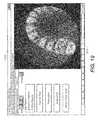
- FIG. 5 shows a plurality of panoramic images of an unfolded curved slab that is formed by the regions covered by the concentric curves.
- FIG. 6A is a view of a panoramic image with a bounding box that indicates the area of an object of interest.
- FIG. 6B is a schematic diagram that shows the use of a bounding box for identifying an object sub-volume from a composite panoramic image.
- FIG. 7 is a flowchart showing processes of mapping area of an object of interest to CBCT images.
- FIG. 8 is a view of one of the CBCT images with the mapped separation curves.
- FIG. 9 shows a plurality of images of a sub-volume that contain an object of interest.
- FIG. 10 is a view of segmentation results for an example tooth.
- FIG. 11 is a view of a seed placement scheme for segmentation.
- FIG. 12 is a view showing a segmentation scheme that accepts an operator stroke on the image for defining foreground and background image elements.
- FIG. 13 is a logic flow diagram that shows a sequence of operations for viewer-assisted segmentation.
- FIG. 14 is a plan view of an operator interface for viewer-assisted segmentation.
- FIG. 15A is a plan view of an operator interface for viewer-assisted segmentation showing a boundary marking scheme according to an embodiment of the present invention.
- FIG. 15B is an enlarged plan view showing boundary curves generated according to user input.
- FIG. 16A is a plan view of an image slice that shows multiple teeth.
- FIG. 16B is a plan view of an operator interface for viewer-assisted segmentation showing an alternate boundary marking scheme according to an embodiment of the present invention.
- FIG. 17 is a plan view of an operator interface showing foreground seed curve generation for a boundary marking scheme according to an embodiment of the present invention.
- FIG. 18A is a plan view of an operator interface showing background seed curve generation for a boundary marking scheme according to an embodiment of the present invention.
- FIG. 18B is a plan view of an operator interface showing background seed curve generation for a boundary marking scheme according to another embodiment of the present invention.
- FIG. 19 is a plan view of an operator interface showing geometric primitives traced onto a volume image.
- FIG. 20 is a plan view of an operator interface showing a tooth having multiple structures.
- FIG. 21 is a plan view of an operator interface showing operator tracing onto the structures of FIG. 20 .
- FIG. 22 is a plan view of an operator interface showing foreground and background seed curves generated according to user input.
- FIG. 23 is a plan view of an operator interface showing adjustment of background seed curves to correct for near proximity and overlap with foreground seed curves.
- FIG. 24 is a logic flow diagram that shows the processing sequence for overlap compensation.
- FIG. 25 is a perspective view that shows over-segmentation with false positives.
- FIG. 26A is a logic flow diagram showing segmentation steps according to an embodiment of the present invention.
- FIG. 26B is a schematic diagram that shows a set of image slices with markup provided on a number of member image slices from the set.
- FIGS. 27A , 27 B, 27 C, 27 D, and 27 E are plan views of marked-up image slices for providing segmentation hints.
- FIG. 28 is a perspective view that shows processing results for a segmented object of interest, without the false positives shown in the example of FIG. 25 .
- object of interest or “feature of interest” generally indicate an object such as a tooth or other object in the mouth.
- set refers to a non-empty set, as the concept of a collection of elements or members of a set is widely understood in elementary mathematics.
- subset unless otherwise explicitly stated, is generally used herein to refer to a non-empty proper subset, that is, to a subset of the larger set, having one or more members.
- a subset may comprise the complete set S.
- a “proper subset” of set S is strictly contained in set S and excludes at least one member of set S.
- GUI Graphical User Interface
- image data element refers to a pixel (2D) or a voxel (3D) according to context.
- a “geometric primitive” has its standard meaning, referring to a two-dimensional shape or form that may be open or closed and can include, for example, a freeform or scribbled shape as well as a triangle, rectangle or other polygon, curve or set of curves or arcs, circle, ellipse, rounded form, or the like.
- the subject matter of the present invention relates to digital image processing and computer vision technologies, which is understood to mean technologies that digitally process data from a digital image to recognize and thereby assign useful meaning to human-understandable objects, attributes, or conditions, and then to utilize the results obtained in further processing of the digital image.
- a sequence of steps used for tooth segmentation for a dental Cone Beam Computed Tomography (CBCT) volume is grouped as an object sub-volume extraction step 100 , shown in dashed outline, followed by a segmentation step 118 .
- the CBCT volume also termed a CT volume herein, is acquired in an image data acquisition step 102 .
- a computed tomography (CT) volume contains image data elements for one or more images (or equivalently, slices). As each image slice is obtained, image data elements are 2-D pixel elements. For the reconstructed volume image, image data elements are 3-D voxel elements.
- An original reconstructed CT volume is formed using standard reconstruction algorithms known in the art, using multiple projections or sinograms obtained from a CT scanner. Normally, only a fraction or subset of the images that form the volume contain teeth or other high density features of interest and is selected for processing; the rest of the CT reconstructed volume accurately represents soft tissue or air.
- this identification of a subset of images for this procedure is done in an image selection step 104 .
- a number of neighboring high density objects or other features of interest in an image (or slice) forms a first region.
- a number of neighboring high density objects or other features of interest in another image (or slice) forms another region.
- FIG. 2 shows an exemplary dental CBCT volume that contains three slices (S 1 202 , S 2 212 , and S 3 222 ) considered from a top view with respect to the teeth.
- Examples of high density objects are teeth O 1 204 and O 2 208 shown in slice S 1 202 .
- objects O 1 204 and O 2 208 are parts of two neighboring teeth. All of these high density objects including O 1 and O 2 in slice S 1 constitute a region in slice S 1 .
- high density objects like O 1 and O 2 in slice S 2 constitute a region in slice S 2 .
- slice S 3 shows an exemplary dental CBCT volume that contains three slices (S 1 202 , S 2 212 , and S 3 222 ) considered from a top view with respect to the teeth.
- Examples of high density objects are teeth O 1 204 and O 2 208 shown in slice S 1 202 .
- objects O 1 204 and O 2 208 are parts of two neighboring teeth. All of these high density objects including O 1 and O
- the features of interest include high density objects (teeth in this case) collectively are arranged along a geometrically curved arcuate or arch shape.
- This shape can be traced by defining a set of substantially concentric curves as shown in FIG. 3A .
- These substantially concentric curves serve as a type of mathematical foliation or topological decomposition, with the corresponding volume decomposed into a set of two-dimensional subspaces.
- the subspaces roughly model the basic form of the dental arch.
- the standard decomposition of a volume into a set of slices can be considered to be a type of foliation; although this foliation does not share a number of the same properties of the foliation of the current invention.
- One property of the current foliation shown in FIG. 3A and applied in this processing is that there is a diffeomorphism between a plane and each leaf of the foliation.
- the leaves of the respective foliations intersect a standard slice of a CT volume along a curve.
- a family of leaves of this foliation appear as a series of concentric curves, as suggested in FIG. 3A .
- Exemplary concentric curves including curve C 1 302 and curve C 2 304 are shown in slice S 1 202 .
- the curves should cover (enclose) or define the features of interest, here, the region that is constituted of high density objects, teeth in this case.
- An exemplary region R 1 306 is shown in slice S 1 .
- another exemplary region is similarly formed in slice S 2 , or slice S 3 and other image slices S 4 , S 5 , . . . Sk taken from this perspective.
- First and second curved paths are considered substantially concentric wherein the curved paths can be said to have the same basic shape, at different scale, and wherein the distance between the first and second curved paths at any point varies by no more than about 20% from the average distance value between them.
- two arcs are considered substantially concentric when their centers are spaced apart from each other by no more than about 30% of the radius of the larger arc.
- a curved sub-volume definition step 106 the curvature of the dental arch is detected and used as a feature to form a curved or curved arch sub-volume for assisting in tooth segmentation.
- one or more substantially concentric curves are formed, traced, or otherwise identified over the at least feature of interest.
- FIG. 3B by stacking the regions that are defined along these concentric curves, that is, stacking of region R 1 306 from slice S 1 in FIG. 3A and corresponding regions R 2 , R 3 , . . . Rk from slices S 2 , S 3 , . . . Sk that would be defined in the same way, a curved slab can be formed as an curved sub-volume 130 , containing one or more of the features of interest, here, regions of one or more high density objects cropped from the larger image volume.
- FIG. 3B shows schematically how the segmentation sequence of the present invention proceeds to generate one or more panoramic views 140 from a dental CT volume 120 .
- a first set of operations through step 106 in FIG. 1 , generate the curved slab of curved sub-volume 130 , from the original CT volume 120 .
- An unfold line computing step 108 then provides a utility that will be used subsequently for unfolding the curved sub-volume 130 along a selected curve to generate the desired flattened or unfolded panoramic view 140 . In its effect, this maps the leaf of the foliation back to a plane, which can be readily manipulated and viewed as an image.
- the curved sub-volume 130 is formed by stacking slices aligned generally along a first direction.
- Unfolding then operates in a planar direction that is orthogonal to this first direction, as shown in the view of an unfolded slab, termed an unfolded sub-volume 134 .
- image data elements that lie along or nearby each fold line are re-aligned according to a realignment of the fold lines. This realignment generally aligns the fold lines from their generally radial arrangement to a substantially parallel orientation. Image data elements that were initially aligned with the fold lines in the original, generally radial arrangement follow the fold line re-orientation, effectively “flattening” the curved sub-volume with little or no distortion of the tooth and its position relative to other teeth.
- Unfolded sub-volume 134 can be visualized as a stacked series of vertical slice images V 1 , V 2 , . . . Vj, as shown. Each vertical slice provides a panoramic image obtained at some depth within unfolded sub-volume 134 . Subsequent steps then present the unfolded views to the user as a type of index to the volume that is to be segmented. That is, selection from the unfolded view enables the user to provide hint (or seed) information that is used for the subsequent segmentation of the tooth or other object.
- the one or more concentric curves or curved paths in FIG. 3A could be traced using an automated approach or a semi-automatic approach.
- slice S 1 can be processed through a sequence of steps that include noise filtering, smoothing, intensity thresholding, binary morphological filtering, medial curve estimation, and pruning to identify a first curve that fits or approximates the arch shape of the teeth region.
- Subsequent concentric curves can then be defined using the shape and position of the first estimated curve as a starting point.
- Forming curved sub-volume 130 helps to reduce the amount of data that is processed for segmentation of the tooth or other object, but the arch or curved sub-volume itself is difficult to work with for identification of an object in segmentation processing.
- the next step in FIG. 1 is an unfold line computing step 108 .
- a series of unfold lines L 1 , L 2 , . . . Ln are defined for facilitating the unfold operation.
- unfold lines L 1 , L 2 , . . . Ln are generated using the same set of concentric curves that were used to define curved sub-volume 130 .
- Each unfold line is substantially perpendicular, to within +/ ⁇ 8 degrees, at its intersection to concentric curves in the tomographic image space of curved sub-volume 130 .
- Exemplary perpendicular unfold lines are shown as lines L 1 402 and L 2 404 in FIG. 4 .
- FIGS. 3B and 4 show only a few representative unfold lines for better visibility and description.
- Unfold lines are projected generally radially outward across curved sub-volume 130 , so that each unfold line extends at least from an inside curved surface 136 to an outside curved surface 138 as shown in FIG. 3B .
- each unfold line intersects a number of image data elements, voxels (in 3-D representation) or pixels (in 2-D representation), that will subsequently be re-aligned in the unfolding operation that follows.
- a medial curve that is, a curve substantially centered within the arch shape region in slice S 1 , is itself sufficient for use in defining a plurality of unfold lines, such as lines L 1 402 and L 2 404 in FIG. 4 , with each unfold line perpendicular to the medial curve of the arch-shaped region in S 1 .
- a further step in the segmentation processing sequence of FIG. 1 “unfolds” the curved sub-volume obtained in step 106 , realigning voxels (pixels) using the perpendicular unfold lines L 1 , L 2 , . . . Ln computed in step 108 .
- the curved slab of the curved sub-volume 130 containing one or more of the regions of one or more high density objects, is unfolded with the help of the computed unfold lines L 1 , L 2 , . . . Ln perpendicular to the concentric curves.
- the same unfolded sub-volume 134 can be represented as a stack of images, in an orthogonal direction, of the original stacked plane. That is, the curved sub-volume 130 in FIG. 3B could alternately be considered as shown in unfolded sub-volume 134 and in FIG. 5 , as a stack of vertical slice images V 1 , V 2 , . . . VM. Each of these VM stacked images has a dimension of K ⁇ N. Images V 1 ( 504 ), V 2 ( 506 ) . . . VM ( 508 ) in FIG. 5 are referred to as panoramic images.
- Embodiments of the present invention not only provide the unfolding method for obtaining individual panoramic images as vertical slice images Vm, but also combine the individual images to form a composite vertical slice image V 0 , formed by averaging, summing, or otherwise combining the individual vertical slice images V 1 , V 2 , . . . VM, that can be useful for improved segmentation processing.
- FIG. 5 an actual computed example of image V 0 ( 502 ) is shown in FIG. 5 .
- unfolded sub-volume 134 Once unfolded sub-volume 134 has been generated, operator interaction assists an automated process in order to define an object sub-volume that includes a single tooth or other object to be segmented.
- an area identification step 112 identifies an area enclosing an object of interest in the unfolded region. This provides information that is employed for identifying an object sub-volume. Step 112 can be executed in a straightforward manner with a computer or other processor by displaying the planar, unfolded image (for example, displaying composite image V 0 ), and obtaining, from operator instructions, spatially and geometrically meaningful information regarding the object of interest.
- the operator provides information that outlines a particular tooth from the composite image, using a pointing device such as a computer input device, mouse, or other pointer or on a touch screen display, for example.
- a pointing device such as a computer input device, mouse, or other pointer or on a touch screen display, for example.
- the operator defines a bounding box surrounding the tooth or other object; however, other outlining and selection shapes or inputs could alternately be used for this purpose.
- FIG. 6A shows a bounding box B 2 ( 602 ) enclosing a tooth Q 2 ( 608 ) displayed in image V 0 ( 502 ).
- tooth Q 2 corresponds to object O 2 ( 208 ) in FIG. 2 .
- neighboring object O 1 ( 204 ) in FIG. 2 becomes tooth Q 1 ( 604 ).
- this location definition can also be entered using any of the other panoramic images of vertical slices V 1 , V 2 , . . . VM of FIG. 5 .
- this bounding box B 2 is used in a mapping step 114 for mapping the identified area to the CBCT volume to generate a sub-volume that encloses the object of interest (that is, O 2 ) in the CBCT volume constituted by slices S 1 , S 2 , S 3 . . . etc. in FIG. 2 .
- B 2 Top 612
- B 2 Bottom 614
- the gap G 1 ( 206 ) in FIG. 2 is denoted by g 1 ( 606 ) in FIG. 6A .
- FIG. 6B shows, from top and side views, how bounding box edges are used to help define an object sub-volume 710 that encloses an object. Bounding box edges help to define starting points for algorithmic techniques that detect gaps indicating edges between teeth.
- mapping step 114 of the FIG. 1 sequence begins using the left and right edge positions to find gaps between neighboring teeth or other objects.
- FIG. 7 depicts the work flow of such an operation, consistent with an embodiment of the present invention.
- an edge e.g. B 2 Left in FIG. 6A
- a first panoramic image e.g. V 1
- two neighboring objects e.g. Q 1 and Q 2
- the gap position is recorded. This initial gap position is then used as a starting point in a subsequent gap detection step 704 that detects another gap position between two objects in the next panoramic image (e.g. V 2 ). The newly found gap position is similarly recorded. This process of searching for gaps between neighboring objects in panoramic images repeats, working successively through each vertical slice image Vn in unfolded sub-volume 134 .
- a decision step 706 determines whether or not all vertical slice images are processed.
- a mapping step 708 the recorded gap positions are mapped back to the CBCT volume space to form a first separation curve between two objects in the CBCT volume, defining the border between the two teeth or other objects.
- the perpendicular lines (L 1 , L 2 , . . . Ln, . . . LN) that were obtained as described with reference to FIG. 4 are used in the mapping process.
- FIG. 8 shows two exemplary separation curves K 1 810 and K 2 812 formed in this manner.
- the four end points e 1 ( 820 ), e 2 ( 822 ), e 3 ( 824 ) and e 4 ( 826 ) determine four position vectors (x 1 , y 1 ), (x 2 , y 2 ), (x 3 , y 3 ) and (x 4 , y 4 ).
- xLeft min( x 1, x 2, x 3, x 4)
- x Right max( x 1, x 2, x 3, x 4)
- y Top min( y 1, y 2, y 3, y 4)
- y Bottom max( y 1, y 2, y 3, y 4)
- mapping step 114 of FIG. 1 the positions of B 2 Top and B 2 Bottom are also mapped back to CBCT space.
- K is the number of slices in the CBCT volume.
- z that is, pointing into the paper in FIG. 8 .
- an extraction step 116 extracts an object sub-volume (SV) 710 that encloses the object of interest.
- object sub-volume 710 is then used to obtain data from CT volume image 120 .
- Display of the segmented tooth generally follows segmentation.
- An exemplary tooth segmentation result of the present invention is presented in FIG. 10 .
- segmentation step 118 Following the extraction of the sub-volume the segmentation of the object of interest is carried out in a segmentation step 118 .
- segmentation As noted previously in the background section, a number of segmentation methods are available for this purpose and are known to those skilled in the image analysis and processing arts.
- a user-guided interactive segmentation method utilizes eyegaze information as an input.
- the method includes three steps: 1) eye gazee tracking for providing user input, setting object (foreground) and background seed pixel selection; 2) an optimization method for image labeling that is constrained or affected by user input; and 3) linking the two previous steps via a graphical user interface for displaying the images and other controls to the user and for providing real-time visual feedback of eye-gaze and seed locations enabling the interactive segmentation procedure.
- FIG. 11 shows an example used by Sadgeghi et al. where there are shown a lesion 1102 and background seeds (e.g. 1104 , 1106 ) and foreground seeds (e.g. 1108 , 1110 ) identified using eyegaze tracking.
- FIG. 12 illustrates an example used by Jolly and Grady where there are shown a lesion 1202 , a foreground stroke 1204 entered by a user and a background circle 1208 formed in response by a computer that can be used to obtain background seeds.
- region seeds can be defined using a mouse click point/selection or by using pixels identified after the stroke, such as background circle 1208 , for example.
- Background seeds can be identified using circle 1208 or stroke 1204 .
- These researchers also stress the value of learning an intensity model, from the pixels on stroke 1204 , for the lesion that is being segmented. With this approach, however, lesion shape information is missing from the user instruction.
- background seeds are limited to a system-generated circle shape, with size and location determined by the stroke placed by the user.
- a suitable segmentation method is the GrowCut segmentation algorithm (see “GrowCut—Interactive Multi-Label N-D Image Segmentation By Cellular Automata,” by Vladimir Vezhnevets, and Vadim Konouchine, Int'l Conf. Computer Graphics and Vision 2005).
- the seeds for different type of regions of interest e.g. foreground and background
- Embodiments of the present invention provide improved ways for placing (or editing) seeds in displayed medical images using geometric primitives, traced with reference to the image by the user.
- FIG. 13 is a logic flow diagram that shows basic steps that are used for user-assisted segmentation processing for segmenting a feature of interest according to an embodiment of the present invention.
- This processing runs on a computer or other logic processor, or on a networked processor, for example.
- a volume image such as a CT or CBCT image, an MRI image, or other volume image type is acquired.
- the volume image is generated on a suitable volume image acquisition system and image data elements for the volume image are typically stored and obtained from an electronic memory, such as in a non-volatile data storage apparatus.
- a volume or sub-volume of interest is identified from the volume image in a VOI identification step 1010 , such as using the method outlined previously for the dental arch, for example.
- a display step 1020 the viewer selects an appropriate view for providing segmentation markup, such as by paging through successive slices of an image of the VOI until a suitable slice displays.
- an obtain user input step 1030 operator instructions for specifying seed data for segmenting an object of interest are obtained.
- the system responds to the user input by automatically generating foreground and background seed curves, used to obtain foreground and background data values, and displaying background hint information to the viewer in an identification step 1040 .
- a segmentation step 1050 then executes segmentation based on the object or feature of interest identified and the foreground and background information that is generated as a result, to provide the tooth segmentation result of the present invention, as was shown in the example of FIG. 10 .
- the segmentation results appear in a display step 1060 . Once results are displayed, the viewer has the option to execute steps 1030 and 1040 again and to re-initiate segmentation in order to refine the initial segmentation results.
- User editing interface 1300 provides the user with a number of exemplary functions and controls that facilitate seed style (or geometric primitive) selection, drawing, and correction. These functions are invoked by various screen selections, clicking on or pointing to and activating relevant control buttons, such as using a mouse pointer, touch screen, or other pointing devices, followed by tracing or other motion by the user.
- Embodiments of the present invention apply one or more computer graphic utilities to the problem and enable the viewer to enter one or more segmentation seeds, with viewer selection of an appropriate seed style for the displayed image, using a predetermined set of graphics primitives. The graphics primitives are then used to generate foreground and background seed curves, as described subsequently.
- Different seed styles can be selected using the interface of FIG. 14 .
- Tools for selection and seed style entry include mouse, touch screen, and other available pointer and input devices.
- One exemplary seed style that can be selected uses a random freeform or “scribble” pattern, accessed using an on-screen control 1304 .
- Selection of control button 1304 along with a control 1312 displays a region of interest of a tooth.
- the viewer can then trace a foreground identifying pattern 1334 in a displayed image slice 1301 , using the user interface for a tooth region 1302 .
- selection of another control 1314 specifies other regions, instructing the system to generate and display a background seed curve 1332 over the background area.
- Another exemplary seed style or geometric primitive that can be selected by the viewer is a “parallel track” primitive, initiated at a control 1306 using the interface of FIG. 14 .
- a “parallel track” primitive is shown.
- Selection of control 1306 enables the user to draw a foreground identifying pattern 1404 in image slice 1301 for tooth region 1302 .
- the underlying “intelligent track” function invoked by selection of button 1306 then automatically draws a background seed curve 1406 for the background, corresponding to the foreground identifying pattern.
- FIG. 15B illustrates how the intelligent track is generated according to an embodiment of the present invention.
- a tooth region 1412 in an image 1410 .
- the user draws a foreground identifying pattern that defines a foreground seed curve 1414 , as described in more detail subsequently, inside the tooth region 1412 near the tooth region boundary.
- the method of the present invention identifies a portion 1416 of image 1410 bounded on one side of curve 1414 and another portion 1418 of image 1410 on the other side as illustrated in FIG. 15B .
- the portion 1416 could be of an exemplary rectangular shape or other appropriate shape.
- Portion 1418 could also be a rectangular or other shape.
- An average intensity value A 1 is computed for portion 1412
- an average intensity value A 2 is computed for portion 1418 .
- a background seed curve 1420 is drawn automatically as shown in FIG. 15B .
- Seed curve 1420 is parallel to seed curve 1414 with a predetermined distance d 1422 between them.
- FIG. 16A Another exemplary seed style or geometric primitive that can be selected by the viewer is a “parallel convex hull”, using a control 1308 in FIG. 14 .
- FIG. 16A there is shown an image 1500 that displays a tooth region 1504 , a tooth region 1502 and a tooth region 1506 .
- tooth region 1504 and tooth region 1506 become part of the background.
- FIG. 16B the user draws, within the tooth region, a foreground identifying pattern 1602 that contains a plurality of 2D points, a subset of which consists of “extreme” 2D points that are purposely placed near the tooth region boundaries and can be used to define the foreground seed curve that bounds foreground values used for segmentation.
- An exemplary set of “extreme” 2D points 1612 , 1614 , 1616 , 1618 , 1620 , 1622 , 1624 , 1626 , 1628 , 1630 , and 1632 are shown in FIG. 16B .
- FIG. 17 illustrates an exemplary foreground seed curve 1702 with exemplary “extreme” points indicated.
- foreground seed curve 1702 is generated automatically as the result of processing by the system, using information obtained from the graphics primitives traced by the user as the foreground identifying pattern.
- Foreground seed curve 1702 bounds foreground seed values to be used by subsequent segmentation processing.
- the background seed curve is formed to generally encompass or surround the area bounded by the foreground seed curve, spaced apart from the foreground seed curve and lying outside the foreground seed curve by a predetermined distance. Background values from the background seed curve are obtained from image data elements at the positions of the background seed curve or lying outside the background seed curve and, optionally, within a distance from the background seed curve, such as within no more than 10 pixels or 10 voxels away from the background seed curve, for example.
- the subset of “extreme” 2D points are identified by applying a convex-hull detection algorithm to the foreground identifying pattern 1602 .
- Convex hull techniques are familiar to those skilled in the image processing arts.
- One exemplary convex hull detection algorithm is published in “An Efficient Algorithm for Determining the Convex Hull of a Finite Point Set”, by Ronald Graham, Info. Proc. Letters 1, 132-133 (1972).
- FIG. 18A shows a resultant convex hull 1804 for the foreground seed curve selection.
- this initial inner or foreground convex hull 1804 is then used as a source to automatically generate a “parallel” outer or background convex hull 1802 or outline that encompasses the foreground convex-hull and that serves as the background seed curve for use in a subsequent segmentation procedure (previously described) that provides the background seed value.
- Convex hull 1802 extends across tooth regions 1504 and 1506 , with image data elements that are regarded as background in this example.
- the foreground seed curve for providing foreground seed values and for generating the “parallel” outer convex hull that provides the background seed curve could be any arbitrary geometric primitives that contain a set of “extreme” points that are near the tooth region boundaries.
- the background convex hull, or outer convex hull, such as convex hull 1802 in FIG. 18A is an outline that encompasses the foreground convex hull and can be determined using a sequence such as the following:
- the inner or foreground convex hull is omitted while the outer or background convex hull along with original user entries 1602 are displayed.
- image data elements that relate to the region or feature of interest and that are spatially bounded within the foreground seed curve are then used for selection of the foreground seed for segmentation.
- foreground seed values are generated from values on and/or within inner foreground convex hull 1804 .
- the background seed curve is spaced apart from and spatially bounds the foreground seed curve, as shown at convex hull 1802 in FIG. 18A .
- Image data elements that on or lie outside the background seed curve are then used for generation of the background seed value. Points that lie between the foreground and background seed curves are not used for background or foreground seed generation.
- image data elements that lie between inner hull 1804 and outer convex hull 1802 are not used as seed elements for segmentation but for the subject of segmentation.
- foreground seed curves illustrated in FIG. 16B and FIG. 17 are single-stroke continuous curves, in practice they could be formed using multiple dots, lines, polygons, or arbitrary shaped curves or mixed geometric primitives.
- the above described method can be applied to one or more slices in a sub volume such as the exemplary slices SV 1 ( 902 ), SV 2 ( 904 ), SV 3 ( 906 ), and SVJ ( 908 ) shown in FIG. 9 .
- the editing interface 1300 of FIGS. 14 , 15 A, and 16 B- 18 B also provides the user with seed correction utilities.
- an “Eraser” control 1310 the user can remove an individual seed curve or pattern such as background seed curve 1406 or foreground identifying pattern 1404 , such as by drawing a line across or otherwise selecting the individual seed curve, pattern, or portion of a pattern that is to be removed.
- the user can further remove all seed curves in a current slice that is displayed by clicking/selecting “Erase Current Labels” control 1322 .
- the user has the option to swap the foreground and background seed curves in a current slice that is displayed by selecting a “Swap Labels” control 1320 .
- Original foreground seed curves then become background seed curves, and original background seed curves become foreground seed curves.
- the viewer also has the option to remove all the seed curves, background and foreground, in a sub volume by selecting a “Reset Labels” control 1318 . This feature allows the viewer to re-edit foreground and background seed curves.
- the preferred GrowCut segmentation algorithm is then applied to the sub volume after the viewer selects a “Segment Tooth” control 1316 .
- step 116 in FIG. 1 the method described hereinabove with reference to FIGS. 2-8 could be used for extracting an object sub-volume from the CBCT or other volume image.
- An alternate method for extracting the sub-volume is shown in FIG. 19 in which the whole CBCT image 1902 is presented.
- the user selects a tooth or other feature of interest by entering a pattern 1904 that may consist of points, lines or scribbles, for example. Similar patterns to pattern 1904 may be entered in different slices that contain the region of interest of a volumetric object, for example a tooth in a CBCT volume.
- the method of the present invention computes a proper bounding cubic volume that encloses the tooth of interest.
- the entered patterns are also used to generate the inner or foreground seeds and outer or background seeds previously discussed.
- the segmentation steps described above are then applied to the sub set of the images within the bounding volume.
- Embodiments of the present invention are particularly well-suited to address difficulties presented in tooth segmentation.
- the relatively complex structure of the tooth can make it difficult to accurately execute segmentation where a tooth is the feature of interest.
- Root structure for example, tends to confound conventional segmentation algorithms; depending on the location of the slice in a tooth volume, segmentation can tend to over- or under-segment the structure, such as by inadvertently bridging the gap between roots, for example.
- the sequence shown in FIGS. 20-23 shows a case where this can easily occur and how segmentation using methods of the present invention adapts to handle complex structures such as portions of the tooth.
- FIG. 20 shows an image 2000 that provides a sectioned view of the tooth showing structures 2002 , 2004 , 2006 that can be parts of the same tooth, such as a portion of the root structure, for example.
- Conventional segmentation methods may tend to group structures 2002 , 2004 , and 2006 together as a single structure, causing errors or poor performance of subsequent segmentation processing.
- FIG. 21 shows the use of graphics primitives, traced onto the tooth image by the user, for defining the foreground and obtaining foreground seed values.
- scribble tracings 2102 , 2104 , and 2106 are entered by the viewer for this purpose.
- Initial system response for foreground and background definition given the input of FIG. 21 is shown in FIG. 22 .
- Foreground seed curves 2202 , 2204 , and 2206 used for foreground seeding, are first generated according to graphics primitives entry. Background seed curves 2212 , 2214 , and 2216 are then generated based on the foreground seed curves 2202 , 2204 , and 2206 . Overlapping of the seed curves, and of areas very near the seed curves is shown in thicker lines as overlap segments 2222 , 2224 , and 2226 . It can be appreciated that these overlapped curves, defining areas as both foreground and background at the same time, can be sources of confusion to segmentation processing.
- FIG. 23 and the logic flow diagram of FIG. 24 show how this condition is handled, where more than one object of interest is identified in a displayed image, according to an embodiment of the present invention.
- a background seed curve intersects, overlaps, or comes within a predetermined close distance to a foreground seed curve
- An obtain seed information step 2030 obtains the seed information for the foreground feature of interest according to graphics primitives entry by the user, as described previously.
- the system In a foreground seed curve generation step 2040 , the system generates the foreground seed curves used to define the foreground seed information.
- a background seed curve generation step 2050 the system then generates the background seed curve corresponding to each foreground seed curve.
- a test step 2060 checks for overlap or close proximity between any portions of the background seed curves with any part of the foreground seed curves. Where no intersection, overlap, or proximity is detected, segmentation step 1050 can be executed. Where there is a conflict between foreground and background seed curve coverage, as was shown with respect to FIG. 22 , an overlap correction step 2070 executes, systematically removing portions of the background seed curve that violate space defined by the foreground seed curves.
- FIG. 23 shows gaps 2322 , 2324 , and 2326 that are formed by this processing. This effectively removes pixel or voxel values in the corresponding areas of the image from being used as background seeds for segmentation processing in the subsequent segmentation step 1050 .
- FIG. 25 shows an example in which there is an object of interest 2504 and two false positives 2506 .
- False positives 2506 may be, for example, from neighboring teeth or bone structures. False positives often occur from features that touch or very nearly touch.
- FIG. 26A gives a sequence of steps for improved segmentation, with methods that can help to reduce or eliminate false positives such as those shown in FIG. 25 .
- An image data acquisition step 2602 obtains the volume image from its set of individual projection images, as described previously with respect to FIG. 1 .
- image slices from the reconstructed volume image are then presented to the viewer for markup of foreground content that defines the region of interest (ROI) for identifying the object of interest.
- ROI region of interest
- the viewer is able to page through and mark up one or more members of a set of image slices.
- FIG. 26B shows, in thumbnail image form, a set 2680 of image slices.
- Representative slices 2682 , 2684 , 2686 , 2688 , and 2690 ordered from the bottom of the stack of set 2680 to the top in the arrangement shown, are members of set 2680 that are marked by the viewer in a markup step 2620 in this example.
- FIGS. 27A , 27 B, 27 C, 27 D, and 27 E then show marked-up slices 2682 , 2684 , 2686 , 2688 , and 2690 , respectively, at a larger scale.
- markup step 2620 selected members of set 2680 of image slices are marked up by the viewer with a foreground identifying pattern 2704 , similar to the patterning described previously with respect to FIG. 14 .
- a convex hull may be formed as a result of the pattern markup, as described previously, embodiments of the present invention further define a background field array 2706 , represented as a pattern of pixels in the 2-D slices of FIGS. 27A-27E .
- a seed point generation step 2630 From foreground identifying pattern 2704 , a seed point generation step 2630 generates foreground seeds from foreground identifying pattern 2704 and background seeds from background field array 2706 .
- Any number of image slices can be marked-up to provide suggestions/hints for segmentation in markup step 2620 ( FIG. 26A ), such as image slices that are representative of different portions of a tooth as shown in FIG. 26B . It can be appreciated that segmentation processing can be improved with a higher number of marked-up image slices.
- background field array 2706 is generated as a representative set of points identifying image data elements (pixels for 2D, voxels for 3D) that are spaced apart from foreground identifying pattern 2704 by a predetermined distance and that cover and identify an area that contains only background content, not image data elements from the tooth or other object of interest.
- Area coverage that is provided by background field array 2706 helps to prevent segmentation processing from inadvertently associating image data elements (pixels or voxels) in the background content with the object of interest. Using this set of points, any structure that encounters background field array 2706 in segmentation processing can automatically be removed from consideration.
- background field array 2706 consists of points that are at least a given default or operator-adjusted distance from the center of the detected tooth or other object, as indicated by identifying pattern 2704 .
- Background field array 2706 extends all along the periphery of the image in the embodiment that is shown.
- background field array 2706 may display immediately following entry of foreground identifying pattern 2704 .
- Background field array 2706 from pattern marking in a particular slice propagates to adjacent slices over a limited range of slices, such as to the next few slices to each side of a marked slice.
- this propagation continues in a weighted manner, so that markup of a given slice influences adjacent slices, but the influence of markup of a given slice is progressively reduced with increased distance from the given slice.
- a “weighting” is assigned to voxels in other slices, based on the nearest markup information that is available.
- a combining step 2640 combines the identified background content with the volume image data prior to a segmentation step 2650 in which segmentation and display of results are provided. Segmentation algorithms that use the generated background field information can show marked improvement over techniques that simply use seed points generated along or outside a single line. The use of an array of points to define seed points for background content can help to reduce the likelihood of false positives.
- FIG. 28 shows segmented object of interest 2504 as displayed in volume image form, without the false positives shown in the example of FIG. 25 .
- Embodiments of the present invention provide a practical tooth segmentation system that takes advantage of synergistic integration of human operator skills, such as creativity, use of heuristics, flexibility, and judgment, with computational power, speed, capability for exhaustive and accurate processing, reporting, and data access, storage capabilities, and display flexibility.
- the operator can modify the segmentation process after viewing initial results, by editing the position of, adding, or removing boundary points, for example.
- a computer executes a program with stored instructions that perform on image data accessed from an electronic memory, to provide panoramic presentation and tooth segmentation in accordance with the method described.
- a computer program of an embodiment of the present invention can be utilized by a suitable, general-purpose computer system, such as a personal computer or workstation.
- a suitable, general-purpose computer system such as a personal computer or workstation.
- many other types of computer systems can be used to execute the computer program of the present invention, including networked processors.
- the computer program for performing the method of the present invention may be stored in a computer readable storage medium.
- This medium may comprise, for example; magnetic storage media such as a magnetic disk (such as a hard drive) or magnetic tape or other portable type of magnetic disk; optical storage media such as an optical disc, optical tape, or machine readable bar code; solid state electronic storage devices such as random access memory (RAM), or read only memory (ROM); or any other physical device or medium employed to store a computer program.
- the computer program for performing the method of the present invention may also be stored on computer readable storage medium that is connected to the image processor by way of the internet or other communication medium. Those skilled in the art will readily recognize that the equivalent of such a computer program product may also be constructed in hardware.
- the computer program product of the present invention may make use of various image manipulation algorithms and processes that are well known. It will be further understood that the computer program product embodiment of the present invention may embody algorithms and processes not specifically shown or described herein that are useful for implementation. Such algorithms and processes may include conventional utilities that are within the ordinary skill of the image processing arts. Additional aspects of such algorithms and systems, and hardware and/or software for producing and otherwise processing the images or co-operating with the computer program product of the present invention, are not specifically shown or described herein and may be selected from such algorithms, systems, hardware, components and elements known in the art.
Abstract
Description
-
- (i) Define an x-y coordinate system for slice S1 as shown by an
x direction 412 andy direction 414 inFIG. 4 , with an origin at the upper left corner ofslice S1 202 or other suitable location. Suppose there are a total of M concentric curves (C1, C2, . . . Cm, . . . CM), and total of N perpendicular lines (L1, L2, . . . Ln, . . . LN). - (ii) Denote an x position matrix of size M×N by X. Denote a y position matrix of size M×N by Y.
- (iii) Store the x position of an intersection point of Cm and Ln at matrix position X(m,n). The y position of the intersection point of Cm and Ln is stored at Y(m,n).
- (iv) Denote an arbitrary slice by S with the same x−y (x 412 and y 414) coordinate system defined in
FIG. 4 . - (v) Denote an arbitrary intensity image by U of size of M×N.
Define:
- (i) Define an x-y coordinate system for slice S1 as shown by an
U1(m,n)=S1(Y(m,n),X(m,n)),
U2(m,n)=S2(Y(m,n),X(m,n)),
U3(m,n)=S3(Y(m,n),X(m,n)),
UK(m,n)=SK(Y(m,n),X(m,n)),
wherein K is the number of slices that constitute the CBCT volume, in the direction of slices Sk, where k=1 . . . K, contained in the unfolded curved slab of the
V0=(V1+V2+ . . . +VM)/M.
xLeft=min(x1,x2,x3,x4),
xRight=max(x1,x2,x3,x4),
yTop=min(y1,y2,y3,y4),
yBottom=max(y1,y2,y3,y4),
where the min( ) operation selects a minimum value from the entries, while max( ) selects a maximum value from the entries.
zTop=B2Top+zOffset;
and
zBottom=B2Bottom+zOffset,
where 1<=zOffset<<K depending on how
SV=CBCT(xLeft,xRight,yTop,yBottom,zTop,zBottom),
where CBCT( ) operation extracts a sub-volume SV from the CBCT volume using the six parameters xLeft, xRight, yTop, yBottom, zTop, zBottom. As is shown in
-
- a) Compute a geometric center,
C 1812, of the foreground convex hull or inner foregroundconvex hull 1804. - b) Compute the distance CR between the center C 1812 and an “extreme” point R 1814 on inner
convex hull 1804. - c) Extend line CR to CG, wherein point G 1816 is an “extreme” point on the background (outer) convex hull, such that the length CG=A*CR. An exemplary value of A could be 1.5.
- d) Repeat steps b) and c) for other extreme points on inner
convex hull 1804 to obtain corresponding points on outerconvex hull 1802.
- a) Compute a geometric center,
Claims (10)
Priority Applications (3)
| Application Number | Priority Date | Filing Date | Title |
|---|---|---|---|
| US13/467,401 US8929635B2 (en) | 2011-07-21 | 2012-05-09 | Method and system for tooth segmentation in dental images |
| EP12814726.1A EP2734147B1 (en) | 2011-07-21 | 2012-07-19 | Method for segmentation of dental images |
| PCT/US2012/047265 WO2013012966A1 (en) | 2011-07-21 | 2012-07-19 | Method and system for dental images |
Applications Claiming Priority (2)
| Application Number | Priority Date | Filing Date | Title |
|---|---|---|---|
| US13/187,596 US8761493B2 (en) | 2011-07-21 | 2011-07-21 | Method and system for tooth segmentation in dental images |
| US13/467,401 US8929635B2 (en) | 2011-07-21 | 2012-05-09 | Method and system for tooth segmentation in dental images |
Related Parent Applications (1)
| Application Number | Title | Priority Date | Filing Date |
|---|---|---|---|
| US13/187,596 Continuation-In-Part US8761493B2 (en) | 2011-07-21 | 2011-07-21 | Method and system for tooth segmentation in dental images |
Publications (2)
| Publication Number | Publication Date |
|---|---|
| US20130022255A1 US20130022255A1 (en) | 2013-01-24 |
| US8929635B2 true US8929635B2 (en) | 2015-01-06 |
Family
ID=47555787
Family Applications (1)
| Application Number | Title | Priority Date | Filing Date |
|---|---|---|---|
| US13/467,401 Active 2032-06-05 US8929635B2 (en) | 2011-07-21 | 2012-05-09 | Method and system for tooth segmentation in dental images |
Country Status (1)
| Country | Link |
|---|---|
| US (1) | US8929635B2 (en) |
Cited By (7)
| Publication number | Priority date | Publication date | Assignee | Title |
|---|---|---|---|---|
| US20140348405A1 (en) * | 2013-05-21 | 2014-11-27 | Carestream Health, Inc. | Method and system for user interaction in 3-d cephalometric analysis |
| WO2018170030A1 (en) | 2017-03-16 | 2018-09-20 | Carestream Dental Technology Topco Limited | Method for virtual setup with mixed dentition |
| US10937108B1 (en) | 2020-01-17 | 2021-03-02 | Pearl Inc. | Computer vision-based claims processing |
| US20210073977A1 (en) * | 2019-09-05 | 2021-03-11 | Pearl Inc. | Systems and methods for automated medical image annotation |
| US11389131B2 (en) | 2018-06-27 | 2022-07-19 | Denti.Ai Technology Inc. | Systems and methods for processing of dental images |
| US11676701B2 (en) | 2019-09-05 | 2023-06-13 | Pearl Inc. | Systems and methods for automated medical image analysis |
| US11776677B2 (en) | 2021-01-06 | 2023-10-03 | Pearl Inc. | Computer vision-based analysis of provider data |
Families Citing this family (35)
| Publication number | Priority date | Publication date | Assignee | Title |
|---|---|---|---|---|
| WO2014164405A1 (en) * | 2013-03-11 | 2014-10-09 | Carestream Health, Inc. | Method for producing teeth surface from x-ray scan of a negative impression |
| GB2524955A (en) | 2014-04-01 | 2015-10-14 | Scopis Gmbh | Method for cell envelope segmentation and visualisation |
| WO2015168781A1 (en) * | 2014-05-06 | 2015-11-12 | Conceptualiz Inc. | System and method for interactive 3d surgical planning and modelling of surgical implants |
| JP6531115B2 (en) * | 2014-05-22 | 2019-06-12 | ケアストリーム ヘルス インク | Method of 3D cephalometric analysis |
| US9626462B2 (en) | 2014-07-01 | 2017-04-18 | 3M Innovative Properties Company | Detecting tooth wear using intra-oral 3D scans |
| GB201501157D0 (en) | 2015-01-23 | 2015-03-11 | Scopis Gmbh | Instrument guidance system for sinus surgery |
| US10049467B2 (en) | 2015-03-18 | 2018-08-14 | Vatech Co., Ltd. | Apparatus and method for reconstructing medical image |
| US10467753B1 (en) * | 2015-04-07 | 2019-11-05 | Oceanit Laboratories, Inc. | Methods and apparatus for slicing three dimensional medical images along curved anatomical surfaces |
| JP5858188B1 (en) * | 2015-06-15 | 2016-02-10 | 富士ゼロックス株式会社 | Image processing apparatus, image processing method, image processing system, and program |
| US10335250B2 (en) | 2015-10-07 | 2019-07-02 | uLab Systems, Inc. | Three-dimensional printed dental appliances using lattices |
| US10631953B2 (en) | 2015-10-07 | 2020-04-28 | uLab Systems, Inc. | Three-dimensional printed dental appliances using support structures |
| US10624717B2 (en) * | 2015-10-07 | 2020-04-21 | Ulab Systems Inc. | Tooth modeling system |
| US11583365B2 (en) | 2015-10-07 | 2023-02-21 | uLab Systems, Inc. | System and methods for tooth movement as a flock |
| US10357336B2 (en) | 2015-10-07 | 2019-07-23 | uLab Systems, Inc. | Systems and methods for fabricating dental appliances or shells |
| US9999405B2 (en) * | 2016-02-16 | 2018-06-19 | General Electric Company | Method and system for enhanced visualization of a curved structure by automatically displaying a rendered view of a curved image slice |
| US10469730B2 (en) * | 2016-05-18 | 2019-11-05 | Canon Kabushiki Kaisha | Imaging device and control method for simultaneously outputting an image pickup signal and a parallax image signal |
| US11144777B2 (en) * | 2016-06-30 | 2021-10-12 | Rakuten Group, Inc. | Image processing apparatus, image processing method, and image processing program for clipping images included in a large image |
| US10357342B2 (en) | 2016-09-21 | 2019-07-23 | uLab Systems, Inc. | Digital dental examination and documentation |
| US10952821B2 (en) | 2016-09-21 | 2021-03-23 | uLab Systems, Inc. | Combined orthodontic movement of teeth with temporomandibular joint therapy |
| US11364098B2 (en) | 2016-09-21 | 2022-06-21 | uLab Systems, Inc. | Combined orthodontic movement of teeth with airway development therapy |
| EP3308738B1 (en) * | 2016-10-13 | 2020-04-22 | a.tron3d GmbH | Method for cleaning up virtual representation of objects |
| US10368814B2 (en) | 2016-12-30 | 2019-08-06 | Carestream Dental Technology Topco Limited | Method for cephalometric analysis |
| EP4046587A1 (en) | 2016-12-30 | 2022-08-24 | Carestream Dental Technology Topco Limited | Reconstruction of a virtual computed-tomography volume to track orthodontics treatment evolution |
| FR3083903B1 (en) * | 2018-07-13 | 2020-10-09 | Dental Monitoring | PROCESS FOR CUTTING A MODEL OF A DENTAL ARCH |
| US20210390687A1 (en) * | 2018-07-13 | 2021-12-16 | Dental Monitoring | Method for enriching a learning base |
| CN109903396B (en) * | 2019-03-20 | 2022-12-16 | 洛阳中科信息产业研究院 | Tooth three-dimensional model automatic segmentation method based on curved surface parameterization |
| KR102253081B1 (en) * | 2019-05-08 | 2021-05-17 | 주식회사 디오 | Method and Apparatus for detecting of Individual Tooth in Teeth Image |
| US11622843B2 (en) | 2019-06-25 | 2023-04-11 | James R. Glidewell Dental Ceramics, Inc. | Processing digital dental impression |
| JP7423951B2 (en) * | 2019-09-19 | 2024-01-30 | 富士フイルムビジネスイノベーション株式会社 | Image processing device and image processing program |
| US11842484B2 (en) * | 2021-01-04 | 2023-12-12 | James R. Glidewell Dental Ceramics, Inc. | Teeth segmentation using neural networks |
| US11931213B2 (en) | 2020-01-31 | 2024-03-19 | James R. Glidewell Dental Ceramics, Inc. | Semi-automatic system and method using boundary loop segments for segmenting teeth |
| EP4096569A1 (en) * | 2020-01-31 | 2022-12-07 | James R. Glidewell Dental Ceramics, Inc. | Teeth segmentation using neural networks |
| EP4255341A1 (en) | 2020-12-01 | 2023-10-11 | Carestream Dental LLC | Method of optimization in orthodontic applications |
| US20220318989A1 (en) * | 2021-03-31 | 2022-10-06 | James R. Glidewell Dental Ceramics, Inc. | Automatic Clean Up of Jaw Scans |
| CN117455934B (en) * | 2023-12-22 | 2024-03-12 | 中南大学 | Method for enhancing and segmenting abnormal lesion area of oral cavity CT |
Citations (27)
| Publication number | Priority date | Publication date | Assignee | Title |
|---|---|---|---|---|
| US5431562A (en) | 1990-01-19 | 1995-07-11 | Ormco Corporation | Method and apparatus for designing and forming a custom orthodontic appliance and for the straightening of teeth therewith |
| US6210162B1 (en) | 1997-06-20 | 2001-04-03 | Align Technology, Inc. | Creating a positive mold of a patient's dentition for use in forming an orthodontic appliance |
| US6409504B1 (en) | 1997-06-20 | 2002-06-25 | Align Technology, Inc. | Manipulating a digital dentition model to form models of individual dentition components |
| US20040175671A1 (en) | 1997-06-20 | 2004-09-09 | Align Technology, Inc. | Subdividing a digital dentition model |
| US20040227750A1 (en) | 2003-05-14 | 2004-11-18 | Microsoft Corporation | Determining the convex hull of convex polygons with congruent corresponding angles |
| US20060029275A1 (en) * | 2004-08-06 | 2006-02-09 | Microsoft Corporation | Systems and methods for image data separation |
| US20060147872A1 (en) | 2002-09-26 | 2006-07-06 | Andreiko Craig A | Custom orthodontic appliance system and method |
| US20060227131A1 (en) | 2005-04-12 | 2006-10-12 | Thomas Schiwietz | Flat texture volume rendering |
| US20070127801A1 (en) | 2005-12-01 | 2007-06-07 | Martti Kalke | Method for limited angle tomography |
| US7317819B2 (en) | 2002-08-28 | 2008-01-08 | Imaging3, Inc. | Apparatus and method for three-dimensional imaging |
| US7324661B2 (en) | 2004-04-30 | 2008-01-29 | Colgate-Palmolive Company | Computer-implemented system and method for automated and highly accurate plaque analysis, reporting, and visualization |
| US20080118143A1 (en) | 2006-11-21 | 2008-05-22 | Mantis Vision Ltd. | 3D Geometric Modeling And Motion Capture Using Both Single And Dual Imaging |
| US20080136820A1 (en) * | 2006-10-20 | 2008-06-12 | Microsoft Corporation | Progressive cut: interactive object segmentation |
| WO2008092009A2 (en) | 2007-01-24 | 2008-07-31 | Imaging Sciences International Llc | Adjustable scanner |
| US20080232539A1 (en) | 2007-03-20 | 2008-09-25 | Cefla Societa' Cooperativa | Method for the reconstruction of a panoramic image of an object, and a computed tomography scanner implementing said method |
| US7460709B2 (en) | 2004-01-23 | 2008-12-02 | Siemens Medical Solutions Usa, Inc. | System and method for multi-label image segmentation |
| US20080310716A1 (en) * | 2007-06-14 | 2008-12-18 | Siemens Corporate Research, Inc. | Editing of pre-segmented images using seeds derived from contours |
| US20090003672A1 (en) * | 2007-06-15 | 2009-01-01 | Florian Maier | Method for segmenting image data for detecting a liver |
| US20090097727A1 (en) | 2007-10-10 | 2009-04-16 | Siemens Corporate Research, Inc. | 3D General Lesion Segmentation In CT |
| US20100278299A1 (en) | 2007-12-03 | 2010-11-04 | Trophy | Dental x-ray apparatus and associated method |
| US20110137626A1 (en) | 2006-07-19 | 2011-06-09 | Align Technology, Inc. | System and method for automated construction of orthodontic reference objects |
| US8244017B2 (en) | 2010-02-08 | 2012-08-14 | James Jiwen Chun | Constructing three dimensional images using panoramic images |
| US8253778B2 (en) | 2008-03-21 | 2012-08-28 | Takahashi Atsushi | Three-dimensional digital magnifier operation supporting system |
| US20120313941A1 (en) | 2011-06-09 | 2012-12-13 | Xiaoliang Li | System and method for digital volume processing |
| US8594428B2 (en) * | 2006-07-25 | 2013-11-26 | Humaneyes Technologies Ltd. | Interactive segmentation of images with single scribbles |
| US8605973B2 (en) * | 2012-03-17 | 2013-12-10 | Sony Corporation | Graph cuts-based interactive segmentation of teeth in 3-D CT volumetric data |
| US8761493B2 (en) * | 2011-07-21 | 2014-06-24 | Carestream Health, Inc. | Method and system for tooth segmentation in dental images |
-
2012
- 2012-05-09 US US13/467,401 patent/US8929635B2/en active Active
Patent Citations (28)
| Publication number | Priority date | Publication date | Assignee | Title |
|---|---|---|---|---|
| US5431562A (en) | 1990-01-19 | 1995-07-11 | Ormco Corporation | Method and apparatus for designing and forming a custom orthodontic appliance and for the straightening of teeth therewith |
| US6210162B1 (en) | 1997-06-20 | 2001-04-03 | Align Technology, Inc. | Creating a positive mold of a patient's dentition for use in forming an orthodontic appliance |
| US6409504B1 (en) | 1997-06-20 | 2002-06-25 | Align Technology, Inc. | Manipulating a digital dentition model to form models of individual dentition components |
| US20030039389A1 (en) | 1997-06-20 | 2003-02-27 | Align Technology, Inc. | Manipulating a digital dentition model to form models of individual dentition components |
| US20040175671A1 (en) | 1997-06-20 | 2004-09-09 | Align Technology, Inc. | Subdividing a digital dentition model |
| US7317819B2 (en) | 2002-08-28 | 2008-01-08 | Imaging3, Inc. | Apparatus and method for three-dimensional imaging |
| US20060147872A1 (en) | 2002-09-26 | 2006-07-06 | Andreiko Craig A | Custom orthodontic appliance system and method |
| US20040227750A1 (en) | 2003-05-14 | 2004-11-18 | Microsoft Corporation | Determining the convex hull of convex polygons with congruent corresponding angles |
| US7460709B2 (en) | 2004-01-23 | 2008-12-02 | Siemens Medical Solutions Usa, Inc. | System and method for multi-label image segmentation |
| US7324661B2 (en) | 2004-04-30 | 2008-01-29 | Colgate-Palmolive Company | Computer-implemented system and method for automated and highly accurate plaque analysis, reporting, and visualization |
| US20060029275A1 (en) * | 2004-08-06 | 2006-02-09 | Microsoft Corporation | Systems and methods for image data separation |
| US20060227131A1 (en) | 2005-04-12 | 2006-10-12 | Thomas Schiwietz | Flat texture volume rendering |
| US20070127801A1 (en) | 2005-12-01 | 2007-06-07 | Martti Kalke | Method for limited angle tomography |
| US20110137626A1 (en) | 2006-07-19 | 2011-06-09 | Align Technology, Inc. | System and method for automated construction of orthodontic reference objects |
| US8594428B2 (en) * | 2006-07-25 | 2013-11-26 | Humaneyes Technologies Ltd. | Interactive segmentation of images with single scribbles |
| US20080136820A1 (en) * | 2006-10-20 | 2008-06-12 | Microsoft Corporation | Progressive cut: interactive object segmentation |
| US20080118143A1 (en) | 2006-11-21 | 2008-05-22 | Mantis Vision Ltd. | 3D Geometric Modeling And Motion Capture Using Both Single And Dual Imaging |
| WO2008092009A2 (en) | 2007-01-24 | 2008-07-31 | Imaging Sciences International Llc | Adjustable scanner |
| US20080232539A1 (en) | 2007-03-20 | 2008-09-25 | Cefla Societa' Cooperativa | Method for the reconstruction of a panoramic image of an object, and a computed tomography scanner implementing said method |
| US20080310716A1 (en) * | 2007-06-14 | 2008-12-18 | Siemens Corporate Research, Inc. | Editing of pre-segmented images using seeds derived from contours |
| US20090003672A1 (en) * | 2007-06-15 | 2009-01-01 | Florian Maier | Method for segmenting image data for detecting a liver |
| US20090097727A1 (en) | 2007-10-10 | 2009-04-16 | Siemens Corporate Research, Inc. | 3D General Lesion Segmentation In CT |
| US20100278299A1 (en) | 2007-12-03 | 2010-11-04 | Trophy | Dental x-ray apparatus and associated method |
| US8253778B2 (en) | 2008-03-21 | 2012-08-28 | Takahashi Atsushi | Three-dimensional digital magnifier operation supporting system |
| US8244017B2 (en) | 2010-02-08 | 2012-08-14 | James Jiwen Chun | Constructing three dimensional images using panoramic images |
| US20120313941A1 (en) | 2011-06-09 | 2012-12-13 | Xiaoliang Li | System and method for digital volume processing |
| US8761493B2 (en) * | 2011-07-21 | 2014-06-24 | Carestream Health, Inc. | Method and system for tooth segmentation in dental images |
| US8605973B2 (en) * | 2012-03-17 | 2013-12-10 | Sony Corporation | Graph cuts-based interactive segmentation of teeth in 3-D CT volumetric data |
Non-Patent Citations (14)
| Title |
|---|
| Akhoondali et al., "Rapid Automatic Segmentation and Visualization of Teeth in CT-Scan Data", Journal of Applied Sciences, pp. 2031-2044, 2009. |
| Gao et al., "Automatic Tooth Region Separation for Dental CT Images", Proceedings of the 2008 Third International Conference on Convergence and Hybrid Information Technology, pp. 897-901, (2008). |
| Hong Chen, et al., "Tooth Contour Extraction for Matching Dental Radiographs," Pattern Recognition, 2004 ICPR 2004 Proceedings of the 17th International Conference, 4 pages. |
| International Search Report mailed Jan. 30, 2013 for International Application No. PCT/US2012/047268, 3 pages. |
| International Search Report mailed Oct. 30, 2012 for International Patent Application No. PCT/US2012/047265, 11 pages. |
| Krsek et al., "Teeth and jaw 3D reconstruction in stomatology", Proceedings of the International Conference on Medical Information Visualisation-BioMedical Visualisation, 6 pages, 2007. |
| M Sadeghi, G. Tien, G. Hamameh, M.S. Atkins, "Hands-free Interactive Image Segmentation Using Eyegaze", SPIE Medical Imaging 2009, vol. 7260, pp. 72601H1-72601H10. |
| Marie-Pierre Jolly, Leo Grady, "3D general lesion segmentation in CT", ISBI 2008, pp. 796-799. |
| R.L. Graham, "An Efficient Algorithm for Determining the Convex Hull Of A Finite Planar Set", Jan. 28, 1972, Information Processing Letters 1 (1972) pp. 132-133, North-Holland Publishing Company. |
| S.Y.Lee, et al., "Development of a Digital Panoramic X-ray Imaging System for Dental Applications," 2007 IEEE Nuclear Science Symposium Conference Record, vol. 4, pp. 2987-2990. |
| Shah et al. "Automatic tooth segmentation using active contour without edges", 2006, IEEE Biometrics Symposium, 6 pages. |
| Sinop, et al. "A Seeded Image Segmentation Framework Unifying Graph Cuts and Random Walker which Yields a New Algorithm." ICCV 2007. (2007): 1-8. Print. * |
| T.K. Schleyer, et al., "A Preliminary Analysis of the Dental Informatics Literature," Adv Dent Res, 17, pp. 20-24, Dec. 2003. |
| Vladimir Vezhnevets, and Vadim Konouchine ,"GrowCut-Interactive Multi-Label N-D Image Segmentation by Cellular Automata,", Int'l. Conf. Computer Graphics and Vision 2005, 7 pages. |
Cited By (14)
| Publication number | Priority date | Publication date | Assignee | Title |
|---|---|---|---|---|
| US20140348405A1 (en) * | 2013-05-21 | 2014-11-27 | Carestream Health, Inc. | Method and system for user interaction in 3-d cephalometric analysis |
| US9855114B2 (en) * | 2013-05-21 | 2018-01-02 | Carestream Health, Inc. | Method and system for user interaction in 3-D cephalometric analysis |
| US10117727B2 (en) * | 2013-05-21 | 2018-11-06 | Carestream Dental Technology Topco Limited | Method and system for user interaction in 3-D cephalometric analysis |
| WO2018170030A1 (en) | 2017-03-16 | 2018-09-20 | Carestream Dental Technology Topco Limited | Method for virtual setup with mixed dentition |
| US11896452B2 (en) | 2017-03-16 | 2024-02-13 | Carestream Health, Inc. | Method for virtual setup with mixed dentition |
| US11389131B2 (en) | 2018-06-27 | 2022-07-19 | Denti.Ai Technology Inc. | Systems and methods for processing of dental images |
| US10984529B2 (en) * | 2019-09-05 | 2021-04-20 | Pearl Inc. | Systems and methods for automated medical image annotation |
| US20210073977A1 (en) * | 2019-09-05 | 2021-03-11 | Pearl Inc. | Systems and methods for automated medical image annotation |
| US11676701B2 (en) | 2019-09-05 | 2023-06-13 | Pearl Inc. | Systems and methods for automated medical image analysis |
| US11055789B1 (en) | 2020-01-17 | 2021-07-06 | Pearl Inc. | Systems and methods for insurance fraud detection |
| US11328365B2 (en) | 2020-01-17 | 2022-05-10 | Pearl Inc. | Systems and methods for insurance fraud detection |
| US11587184B2 (en) | 2020-01-17 | 2023-02-21 | Pearl Inc. | Computer vision-based claims processing |
| US10937108B1 (en) | 2020-01-17 | 2021-03-02 | Pearl Inc. | Computer vision-based claims processing |
| US11776677B2 (en) | 2021-01-06 | 2023-10-03 | Pearl Inc. | Computer vision-based analysis of provider data |
Also Published As
| Publication number | Publication date |
|---|---|
| US20130022255A1 (en) | 2013-01-24 |
Similar Documents
| Publication | Publication Date | Title |
|---|---|---|
| US8929635B2 (en) | Method and system for tooth segmentation in dental images | |
| US8761493B2 (en) | Method and system for tooth segmentation in dental images | |
| US8849016B2 (en) | Panoramic image generation from CBCT dental images | |
| US11776216B2 (en) | System and method for extracting a region of interest from volume data | |
| US9439610B2 (en) | Method for teeth segmentation and alignment detection in CBCT volume | |
| Chung et al. | Pose-aware instance segmentation framework from cone beam CT images for tooth segmentation | |
| US8842904B2 (en) | Method for tooth dissection in CBCT volume | |
| US7492968B2 (en) | System and method for segmenting a structure of interest using an interpolation of a separating surface in an area of attachment to a structure having similar properties | |
| US8423124B2 (en) | Method and system for spine visualization in 3D medical images | |
| US8970581B2 (en) | System and method for interactive contouring for 3D medical images | |
| US20110254845A1 (en) | Image processing method and image processing apparatus | |
| EP2810217B1 (en) | Graph cuts-based interactive segmentation of teeth in 3-d ct volumetric data | |
| CN112529834A (en) | Spatial distribution of pathological image patterns in 3D image data | |
| CN110706241B (en) | Three-dimensional focus region extraction method and device | |
| CN107194909A (en) | Medical image-processing apparatus and medical imaging processing routine | |
| CN103049638A (en) | Semi-automated preoperative resection planning | |
| US9019272B2 (en) | Curved planar reformation | |
| EP3555852B1 (en) | Method of segmenting a 3d object in a medical radiation image | |
| CN109242947A (en) | Three-dimensional ultrasound pattern display methods | |
| CN106952264B (en) | Method and device for cutting three-dimensional medical target | |
| EP2734147B1 (en) | Method for segmentation of dental images | |
| WO2020173054A1 (en) | Vrds 4d medical image processing method and product | |
| JP2012085833A (en) | Image processing system for three-dimensional medical image data, image processing method for the same, and program | |
| JP2009022307A (en) | Medical image display device and its program | |
| Sourin et al. | Segmentation of MRI brain data using a haptic device |
Legal Events
| Date | Code | Title | Description |
|---|---|---|---|
| AS | Assignment |
Owner name: CARESTREAM HEALTH, INC., NEW YORK Free format text: ASSIGNMENT OF ASSIGNORS INTEREST;ASSIGNORS:CHEN, SHOUPU;RAY, LAWRENCE A.;SIGNING DATES FROM 20120606 TO 20120607;REEL/FRAME:028383/0431 |
|
| AS | Assignment |
Owner name: CREDIT SUISSE AG, CAYMAN ISLANDS BRANCH, NEW YORK Free format text: AMENDED AND RESTATED INTELLECTUAL PROPERTY SECURITY AGREEMENT (FIRST LIEN);ASSIGNORS:CARESTREAM HEALTH, INC.;CARESTREAM DENTAL LLC;QUANTUM MEDICAL IMAGING, L.L.C.;AND OTHERS;REEL/FRAME:030711/0648 Effective date: 20130607 |
|
| AS | Assignment |
Owner name: CREDIT SUISSE AG, CAYMAN ISLANDS BRANCH, NEW YORK Free format text: SECOND LIEN INTELLECTUAL PROPERTY SECURITY AGREEMENT;ASSIGNORS:CARESTREAM HEALTH, INC.;CARESTREAM DENTAL LLC;QUANTUM MEDICAL IMAGING, L.L.C.;AND OTHERS;REEL/FRAME:030724/0154 Effective date: 20130607 |
|
| FEPP | Fee payment procedure |
Free format text: PAYOR NUMBER ASSIGNED (ORIGINAL EVENT CODE: ASPN); ENTITY STATUS OF PATENT OWNER: LARGE ENTITY |
|
| STCF | Information on status: patent grant |
Free format text: PATENTED CASE |
|
| AS | Assignment |
Owner name: CARESTREAM DENTAL LLC, GEORGIA Free format text: RELEASE BY SECURED PARTY;ASSIGNOR:CREDIT SUISSE AG, CAYMAN ISLANDS BRANCH;REEL/FRAME:043749/0243 Effective date: 20170901 Owner name: RAYCO (SHANGHAI) MEDICAL PRODUCTS CO., LTD., CHINA Free format text: RELEASE BY SECURED PARTY;ASSIGNOR:CREDIT SUISSE AG, CAYMAN ISLANDS BRANCH;REEL/FRAME:043749/0133 Effective date: 20170901 Owner name: CARESTREAM HEALTH LTD., ISRAEL Free format text: RELEASE BY SECURED PARTY;ASSIGNOR:CREDIT SUISSE AG, CAYMAN ISLANDS BRANCH;REEL/FRAME:043749/0133 Effective date: 20170901 Owner name: CARESTREAM HEALTH FRANCE, FRANCE Free format text: RELEASE BY SECURED PARTY;ASSIGNOR:CREDIT SUISSE AG, CAYMAN ISLANDS BRANCH;REEL/FRAME:043749/0243 Effective date: 20170901 Owner name: RAYCO (SHANGHAI) MEDICAL PRODUCTS CO., LTD., CHINA Free format text: RELEASE BY SECURED PARTY;ASSIGNOR:CREDIT SUISSE AG, CAYMAN ISLANDS BRANCH;REEL/FRAME:043749/0243 Effective date: 20170901 Owner name: CARESTREAM HEALTH FRANCE, FRANCE Free format text: RELEASE BY SECURED PARTY;ASSIGNOR:CREDIT SUISSE AG, CAYMAN ISLANDS BRANCH;REEL/FRAME:043749/0133 Effective date: 20170901 Owner name: CARESTREAM HEALTH, INC., NEW YORK Free format text: RELEASE BY SECURED PARTY;ASSIGNOR:CREDIT SUISSE AG, CAYMAN ISLANDS BRANCH;REEL/FRAME:043749/0133 Effective date: 20170901 Owner name: CARESTREAM HEALTH, INC., NEW YORK Free format text: RELEASE BY SECURED PARTY;ASSIGNOR:CREDIT SUISSE AG, CAYMAN ISLANDS BRANCH;REEL/FRAME:043749/0243 Effective date: 20170901 Owner name: CARESTREAM DENTAL LLC, GEORGIA Free format text: RELEASE BY SECURED PARTY;ASSIGNOR:CREDIT SUISSE AG, CAYMAN ISLANDS BRANCH;REEL/FRAME:043749/0133 Effective date: 20170901 Owner name: CARESTREAM HEALTH LTD., ISRAEL Free format text: RELEASE BY SECURED PARTY;ASSIGNOR:CREDIT SUISSE AG, CAYMAN ISLANDS BRANCH;REEL/FRAME:043749/0243 Effective date: 20170901 |
|
| AS | Assignment |
Owner name: CARESTREAM DENTAL TECHNOLOGY TOPCO LIMITED, UNITED KINGDOM Free format text: ASSIGNMENT OF ASSIGNORS INTEREST;ASSIGNOR:CARESTREAM HEALTH, INC.;REEL/FRAME:044873/0520 Effective date: 20171027 Owner name: CARESTREAM DENTAL TECHNOLOGY TOPCO LIMITED, UNITED Free format text: ASSIGNMENT OF ASSIGNORS INTEREST;ASSIGNOR:CARESTREAM HEALTH, INC.;REEL/FRAME:044873/0520 Effective date: 20171027 |
|
| MAFP | Maintenance fee payment |
Free format text: PAYMENT OF MAINTENANCE FEE, 4TH YEAR, LARGE ENTITY (ORIGINAL EVENT CODE: M1551) Year of fee payment: 4 |
|
| MAFP | Maintenance fee payment |
Free format text: PAYMENT OF MAINTENANCE FEE, 8TH YEAR, LARGE ENTITY (ORIGINAL EVENT CODE: M1552); ENTITY STATUS OF PATENT OWNER: LARGE ENTITY Year of fee payment: 8 |
|
| AS | Assignment |
Owner name: TROPHY DENTAL INC., NEW YORK Free format text: RELEASE OF SECURITY INTEREST IN INTELLECTUAL PROPERTY (FIRST LIEN);ASSIGNOR:CREDIT SUISSE AG, CAYMAN ISLANDS BRANCH;REEL/FRAME:061683/0441 Effective date: 20220930 Owner name: QUANTUM MEDICAL IMAGING, L.L.C., NEW YORK Free format text: RELEASE OF SECURITY INTEREST IN INTELLECTUAL PROPERTY (FIRST LIEN);ASSIGNOR:CREDIT SUISSE AG, CAYMAN ISLANDS BRANCH;REEL/FRAME:061683/0441 Effective date: 20220930 Owner name: CARESTREAM DENTAL LLC, GEORGIA Free format text: RELEASE OF SECURITY INTEREST IN INTELLECTUAL PROPERTY (FIRST LIEN);ASSIGNOR:CREDIT SUISSE AG, CAYMAN ISLANDS BRANCH;REEL/FRAME:061683/0441 Effective date: 20220930 Owner name: CARESTREAM HEALTH, INC., NEW YORK Free format text: RELEASE OF SECURITY INTEREST IN INTELLECTUAL PROPERTY (FIRST LIEN);ASSIGNOR:CREDIT SUISSE AG, CAYMAN ISLANDS BRANCH;REEL/FRAME:061683/0441 Effective date: 20220930 Owner name: TROPHY DENTAL INC., GEORGIA Free format text: RELEASE OF SECURITY INTEREST IN INTELLECTUAL PROPERTY (SECOND LIEN);ASSIGNOR:CREDIT SUISSE AG, CAYMAN ISLANDS BRANCH;REEL/FRAME:061683/0601 Effective date: 20220930 Owner name: QUANTUM MEDICAL IMAGING, L.L.C., NEW YORK Free format text: RELEASE OF SECURITY INTEREST IN INTELLECTUAL PROPERTY (SECOND LIEN);ASSIGNOR:CREDIT SUISSE AG, CAYMAN ISLANDS BRANCH;REEL/FRAME:061683/0601 Effective date: 20220930 Owner name: CARESTREAM DENTAL LLC, GEORGIA Free format text: RELEASE OF SECURITY INTEREST IN INTELLECTUAL PROPERTY (SECOND LIEN);ASSIGNOR:CREDIT SUISSE AG, CAYMAN ISLANDS BRANCH;REEL/FRAME:061683/0601 Effective date: 20220930 Owner name: CARESTREAM HEALTH, INC., NEW YORK Free format text: RELEASE OF SECURITY INTEREST IN INTELLECTUAL PROPERTY (SECOND LIEN);ASSIGNOR:CREDIT SUISSE AG, CAYMAN ISLANDS BRANCH;REEL/FRAME:061683/0601 Effective date: 20220930 |