US8899984B2 - CT-based, side-loading surgical and laboratory dental implant guide system and method - Google Patents
CT-based, side-loading surgical and laboratory dental implant guide system and method Download PDFInfo
- Publication number
- US8899984B2 US8899984B2 US12/683,319 US68331910A US8899984B2 US 8899984 B2 US8899984 B2 US 8899984B2 US 68331910 A US68331910 A US 68331910A US 8899984 B2 US8899984 B2 US 8899984B2
- Authority
- US
- United States
- Prior art keywords
- grommet
- dental
- master
- tooling head
- implant
- Prior art date
- Legal status (The legal status is an assumption and is not a legal conclusion. Google has not performed a legal analysis and makes no representation as to the accuracy of the status listed.)
- Active, expires
Links
- 238000000034 method Methods 0.000 title claims abstract description 37
- 239000004053 dental implant Substances 0.000 title claims description 134
- 239000007943 implant Substances 0.000 claims description 159
- 238000010276 construction Methods 0.000 claims description 3
- 239000007787 solid Substances 0.000 claims 4
- 210000003128 head Anatomy 0.000 description 108
- 210000000214 mouth Anatomy 0.000 description 68
- 230000008569 process Effects 0.000 description 11
- 210000000988 bone and bone Anatomy 0.000 description 10
- 238000001356 surgical procedure Methods 0.000 description 9
- 238000005266 casting Methods 0.000 description 8
- 238000003780 insertion Methods 0.000 description 8
- 230000037431 insertion Effects 0.000 description 8
- 238000005516 engineering process Methods 0.000 description 7
- 239000000463 material Substances 0.000 description 6
- 238000002591 computed tomography Methods 0.000 description 5
- 210000001519 tissue Anatomy 0.000 description 5
- 230000008901 benefit Effects 0.000 description 4
- 230000037123 dental health Effects 0.000 description 4
- 210000004373 mandible Anatomy 0.000 description 4
- 230000000007 visual effect Effects 0.000 description 4
- RTAQQCXQSZGOHL-UHFFFAOYSA-N Titanium Chemical compound [Ti] RTAQQCXQSZGOHL-UHFFFAOYSA-N 0.000 description 3
- 230000009471 action Effects 0.000 description 3
- 210000004369 blood Anatomy 0.000 description 3
- 239000008280 blood Substances 0.000 description 3
- 230000008859 change Effects 0.000 description 3
- 230000006378 damage Effects 0.000 description 3
- 230000013011 mating Effects 0.000 description 3
- 238000002360 preparation method Methods 0.000 description 3
- 230000002441 reversible effect Effects 0.000 description 3
- 229910052719 titanium Inorganic materials 0.000 description 3
- 239000010936 titanium Substances 0.000 description 3
- NIXOWILDQLNWCW-UHFFFAOYSA-N acrylic acid group Chemical group C(C=C)(=O)O NIXOWILDQLNWCW-UHFFFAOYSA-N 0.000 description 2
- 238000004873 anchoring Methods 0.000 description 2
- 239000003479 dental cement Substances 0.000 description 2
- 238000013461 design Methods 0.000 description 2
- 238000011161 development Methods 0.000 description 2
- 238000003384 imaging method Methods 0.000 description 2
- 238000000338 in vitro Methods 0.000 description 2
- 238000004519 manufacturing process Methods 0.000 description 2
- 210000004877 mucosa Anatomy 0.000 description 2
- 206010065687 Bone loss Diseases 0.000 description 1
- 241000195940 Bryophyta Species 0.000 description 1
- 208000008312 Tooth Loss Diseases 0.000 description 1
- 208000027418 Wounds and injury Diseases 0.000 description 1
- 230000003044 adaptive effect Effects 0.000 description 1
- 239000000853 adhesive Substances 0.000 description 1
- 230000001070 adhesive effect Effects 0.000 description 1
- 230000004075 alteration Effects 0.000 description 1
- 238000013459 approach Methods 0.000 description 1
- 230000003190 augmentative effect Effects 0.000 description 1
- 230000015572 biosynthetic process Effects 0.000 description 1
- 238000004891 communication Methods 0.000 description 1
- 238000007408 cone-beam computed tomography Methods 0.000 description 1
- 238000012790 confirmation Methods 0.000 description 1
- 238000012937 correction Methods 0.000 description 1
- 230000001054 cortical effect Effects 0.000 description 1
- 238000005520 cutting process Methods 0.000 description 1
- 238000005553 drilling Methods 0.000 description 1
- 239000003814 drug Substances 0.000 description 1
- 229940079593 drug Drugs 0.000 description 1
- 238000000605 extraction Methods 0.000 description 1
- 230000001815 facial effect Effects 0.000 description 1
- 238000010348 incorporation Methods 0.000 description 1
- 208000014674 injury Diseases 0.000 description 1
- 210000001847 jaw Anatomy 0.000 description 1
- 210000002698 mandibular nerve Anatomy 0.000 description 1
- 238000013507 mapping Methods 0.000 description 1
- 235000011929 mousse Nutrition 0.000 description 1
- 238000010883 osseointegration Methods 0.000 description 1
- 210000003254 palate Anatomy 0.000 description 1
- 230000000704 physical effect Effects 0.000 description 1
- 229920000642 polymer Polymers 0.000 description 1
- 230000002028 premature Effects 0.000 description 1
- 238000011084 recovery Methods 0.000 description 1
- 230000002787 reinforcement Effects 0.000 description 1
- 238000011160 research Methods 0.000 description 1
- 239000007858 starting material Substances 0.000 description 1
- 230000002123 temporal effect Effects 0.000 description 1
- 210000001835 viscera Anatomy 0.000 description 1
Images


Classifications
-
- A—HUMAN NECESSITIES
- A61—MEDICAL OR VETERINARY SCIENCE; HYGIENE
- A61C—DENTISTRY; APPARATUS OR METHODS FOR ORAL OR DENTAL HYGIENE
- A61C8/00—Means to be fixed to the jaw-bone for consolidating natural teeth or for fixing dental prostheses thereon; Dental implants; Implanting tools
- A61C8/0089—Implanting tools or instruments
-
- A—HUMAN NECESSITIES
- A61—MEDICAL OR VETERINARY SCIENCE; HYGIENE
- A61C—DENTISTRY; APPARATUS OR METHODS FOR ORAL OR DENTAL HYGIENE
- A61C1/00—Dental machines for boring or cutting ; General features of dental machines or apparatus, e.g. hand-piece design
- A61C1/08—Machine parts specially adapted for dentistry
- A61C1/082—Positioning or guiding, e.g. of drills
- A61C1/084—Positioning or guiding, e.g. of drills of implanting tools
-
- A—HUMAN NECESSITIES
- A61—MEDICAL OR VETERINARY SCIENCE; HYGIENE
- A61C—DENTISTRY; APPARATUS OR METHODS FOR ORAL OR DENTAL HYGIENE
- A61C3/00—Dental tools or instruments
- A61C3/02—Tooth drilling or cutting instruments; Instruments acting like a sandblast machine
-
- A—HUMAN NECESSITIES
- A61—MEDICAL OR VETERINARY SCIENCE; HYGIENE
- A61C—DENTISTRY; APPARATUS OR METHODS FOR ORAL OR DENTAL HYGIENE
- A61C8/00—Means to be fixed to the jaw-bone for consolidating natural teeth or for fixing dental prostheses thereon; Dental implants; Implanting tools
- A61C8/0003—Not used, see subgroups
- A61C8/0004—Consolidating natural teeth
- A61C8/0006—Periodontal tissue or bone regeneration
-
- A—HUMAN NECESSITIES
- A61—MEDICAL OR VETERINARY SCIENCE; HYGIENE
- A61C—DENTISTRY; APPARATUS OR METHODS FOR ORAL OR DENTAL HYGIENE
- A61C8/00—Means to be fixed to the jaw-bone for consolidating natural teeth or for fixing dental prostheses thereon; Dental implants; Implanting tools
- A61C8/0018—Means to be fixed to the jaw-bone for consolidating natural teeth or for fixing dental prostheses thereon; Dental implants; Implanting tools characterised by the shape
- A61C8/0022—Self-screwing
Definitions
- the present invention may relate to dental implant systems that use CT technologies to obtain data from a patient's oral cavity to create a surgical implant guide that is used for the preparation and insertion of an implant into a patient's mouth.
- an anchoring means is generally a dental implant comprising of a specially-shaped and constructed post (generally made of titanium, whose qualities allow it to bond well with the bone-a process called osseointegration) that is placed into the bone structure of the mouth to act as the “root(s)” of the prosthetic tooth.
- This placement generally allows a portion of the implant to protrude above the gum line where it is generally surrounded by an structure called an abutment or extension that acts as an adaptive interface for the crown (the prosthetic that is constructed to look like that portion of the tooth, which that is visible in the mouth). This abutment ensures the crown is held in the proper orientation and placement once the crown is permanently affixed to the implant.
- the dental implant technology requires a significant amount of preparation, time, as well as a significant amount of talent, skill, knowledge on behalf of the dental healthcare professional (e.g., the dentist) to ensure that the proper implant placement and proper crown attachment occurs. This is necessary to maintain the patient's correct and proper bite (e.g., the alignment between the mandible and upper plate of the patient mouth.) and to proper dental look. If the proper alignment is not maintained with the newly placed implant, then the patent can be placed into constant pain with misaligned bite as well as suffer premature mandible joint wear. Further, this dental capability is necessary during implant surgery (e.g., drilling, boring, threading the pilot hole for the implant) to prevent damage to critical jaw and facial structures such as the inferior alveolar nerve in the mandible (e.g., the lower jaw).
- implant surgery e.g., drilling, boring, threading the pilot hole for the implant
- an overlaying dental surgical guide also known as a stent, substantially created in the same manner as the model (using CT scanning data or manual creation), can fit over the patient's teeth, bone surface, or mucosa (if all the teeth are missing).
- This dental surgical guide could have one or more CT-designed hollow channels containing reinforcement tubes or grommets that generally connect the top of the dental surgical guide to the bottom of the dental surgical guide.
- the passages or hollow interiors in the grommets can generally guide the dentist's placement of the dental implant appliances (e.g., the tools used to prepare and secure the implant in the patient's mouth).
- the dental health care professional e.g., dentist
- the dental health care professional still needs to possess and exercise considerable skill and artistry to correctly locate, orient, and secure the implant into the mouth bone structure as the dentist still has to properly angle the dental implant appliances correctly though the top-loading dental surgical guide.
- the precision of such systems can be seen as being limited.
- dental surgical guide (either CT-based or manually created) generally adds its own thickness and may substantially limit the availability of oral cavity area that is needed to perform those operations for placing the implant.
- This current limitation may require the patient to open their mouth even further to accommodate the dental implant appliances and the like than if the dental surgical guide was not employed in the first place. While this may not be much of concern regarding implants for lost forward teeth, it can have significant impact for back teeth implant placement, where the patient may be required to open their mouth wider than normal for implant placement resulting in possible over stretching of the temporal mandible joint with resulting significant discomfort, as well as possible physical injury to the patient.
- a dental surgical guide that can be created using CT-based three-dimensional imaging of the patients mouth (combined with impression-based models) that allows for precisely created and placed aperture(s) and corresponding grommet(s) within the dental surgical guide that allow the dental surgical guide to incorporate a wide variety of datum or implant placement control factors such setting the depth of the implant, its x, y, and z axial orientations, telemetry, and the like in the mouth's bone structure.
- datum or implant placement control factors such setting the depth of the implant, its x, y, and z axial orientations, telemetry, and the like in the mouth's bone structure.
- Such incorporation provided in step with a side-loading dental surgical guide with resultant and high precision locating/locking means, could allow the computer-processed datum/implant placement control factors to be utilized in the orientation and operation of dental implant appliances, implant, and implant-related items.
- This side-loading dental surgical guide system could further incorporate various operator notification means (e.g., au
- side-loading dental surgical guide system could provide for the relieved insertion of implant appliances, implant, and implant-related items through the side rather than the top of the dental surgical guide to allow for greater operating room in the mouth as well as not requiring the patient to significantly open their mouth further to accommodate the insertion of tools/implant into the dental surgical guide.
- the side-loading dental surgical guide system could provide a level of control and precision over the planning, guidance, and placement of the implant to a degree previously unheard.
- This greatly improved capability could significantly increase the ease of the dental implant operation; reduce the time and number of individual operations required for the dental implant operation; reduce the dental implant placement recovery time while overall, increase the dental healthcare professional's implant surgery capability.
- Such a capability could accomplish this by significantly replacing a large amount of dental art (skill and talent) ordinarily required for the completion of such dental implant surgical operations with computer-controlled, consistent, accurate, scientific precision.
- the overall result of such a system could provide affordable implant surgery to significantly greater numbers of the public suffering from tooth loss than ever before.
- the indexing means uses visual, tactile, auditory notification means to notify the operator when the correct placement position and orientation of the dental implant appliance/implant has been reached;
- the indexing means uses the lack of visual, tactile, auditory stimulus to notify the operator that the correct placement, position, and orientation of the dental implant appliance/implant has not been reached;
- an side-loading dental surgical guide that can incorporate a wide variety of datum data obtained from CT-Scans, dental impressions, dental castings of the patient's mouth to control placement and operation with greater than before achieved precision of dental implant appliances and the placement of the dental implants as relative to a implant surgical site;
- One possible embodiment of the invention could be a side-loading dental surgical guide comprised of a body with a set of walls, a top portion, and a bottom portion and at least one open-sided channel, the open-sided channel that continuously connects an opening of the one of the set of walls to the top portion and the bottom portion; and at least one open-sided master grommet, the open-sided master grommet having a hollow grommet interior that continuously connects a side opening, a top aperture and a bottom aperture; wherein the open-sided master grommet is placed within a respective open-sided channel to allow a dental tooling head to placed into the master grommet through its side opening.
- One possible embodiment of the invention could be a dental implant guide system comprised of an open-sided dental implant guide with a set of walls, a top portion, and a bottom portion and at least one open-sided channel, the open-sided channel that continuously connects an side opening of the one of the set of walls to the top portion and the bottom portion; at least one open-sided master grommet, the open-sided master grommet being so received within a respective open-sided channel that the channel's open side matches up with the side opening of the master grommet; and a tooling head that is received within the open-sided master grommet
- Yet another embodiment of the invention could be a method of operating an side-loading dental surgical guide comprising of the following steps: providing side-loading dental surgical guide having at least one open-sided channel containing an open-sided master grommet, the open side of the master grommet opening upon the open side of the open-sided channel; providing a tool head that can accommodate a dental implant appliance; moving the tooling head through the open side of the open-sided channel; and placing the tooling head into the master grommet.
- Yet another embodiment of the invention could be a dental implant system comprised of an dental implant guide with a set of walls, a top portion, and a bottom portion and at least one channel, that can receive a master grommet; a tooling head that is received within the master grommet; a dental appliance that is movably received within at least a portion of the master grommet; Wherein the master grommet, the tooling head, and dental appliance form an indexing means that locks the dental appliance to prevent the further rotational movement of the dental appliance after the dental appliance has obtained the desired depth and angle of final rotation with respect to either the implant surgical site or the implant surgical site analogue.
- FIG. 1 is substantially a perspective view of one embodiment of the side-loading dental surgical guide of the present invention as it is applied to an operating area of a patient.
- FIG. 1A is substantially a perspective view of one embodiment of the side-loading dental surgical guide of the present invention as it is applied to 3D translucent model.
- FIG. 2 is substantially a perspective view of one embodiment of the side-loading surgical guide of the present invention.
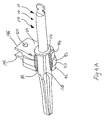
- FIG. 3 is substantially a perspective view of the tooling head of the present invention.
- FIG. 3A is substantially a perspective view of another embodiment of the tooling head for the present invention.
- FIG. 3B is substantially a perspective view of showing tooling head locking notification means for the present invention.
- FIG. 4 is substantially a perspective view for a dental appliance of the present invention.
- FIG. 4A is substantially a perspective cutaway view for a dental appliance in combination with a tooling head.
- FIG. 5 is substantially showing a perspective view of another embodiment of the dental appliance of the present invention.
- FIG. 5A is substantially showing a perspective view of dental appliance indexing means of the present invention.
- FIG. 6 is substantially a perspective view of handle of the present invention.
- FIG. 7 is substantially showing a flow chart for one embodiment of the method for operating the invention.
- FIGS. 8A-8F are perspective cutaway views substantially showing the process using placement of an implant analogue in the translucent 3D model to representing the real life placement of the implant outside of the parameters of the surgical plan.
- the present invention 10 generally comprises a CT data-based, side-loading surgical dental guide system 15 with a method for operating same 300 .
- the system 15 could at least comprise of a side-loading dental surgical guide 20 generally having channel 30 containing a master grommet 40 , wherein at least embodiment the channel 30 could be an open-sided channel 30 and the master grommet 40 could be an open-sided master grommet 40 .
- the system 15 could further comprise of one or more tooling heads 70 that could be reversibly attached and locked into the master grommet 40 .
- the tooling heads 70 being further constructed to hold dental implant appliances 110 to properly prepare, locate, and secure the implant 500 within the bone structure of the patient's mouth/an implant analogue 502 within a model of the patient's mouth 12 ; and further carry out operations of the surgical implant plan.
- the system 15 could further comprise of tooling head-handle 136 that can be reversibly attached to one or more tooling heads 70 for aid in manipulating the tooling head(s) 70 (e.g., along with attached dental implant appliances 110 ) relative to its placement within with the side-loading dental surgical guide 20 .
- the side-loading dental surgical guide 20 could be created using at least datum data obtained from CT scan [e.g., CBCT or Cone Beam Volumetric Image or other suitable DICOM (Digital Imaging and Communications in Medicine) scanning means] of the patient's mouth.
- CT scan e.g., CBCT or Cone Beam Volumetric Image or other suitable DICOM (Digital Imaging and Communications in Medicine) scanning means
- the digital scan data could further augmented with data acquired from manual/physical recordation of the patent's mouth (e.g., a dental impression and resulting casting). All of this data could be processed and integrated by one or more virtual implant planning software programs to create a virtual model of the patient's mouth, the virtual model being used to plan the dental implant surgical plan.
- a physical model 12 e.g., transparent/translucent model
- the side-loading dental surgical guide 20 e.g., stent
- the invention 10 can be produced using computer-controlled standard acrylic methodologies or rapid prototype manufacturing means.
- the side-loading dental surgical guide 20 can be placed on the translucent physical model 12 (having a modeled or surgical implant site analogue 402 ) to indirectly verify fit of the side-loading dental surgical guide 20 to the implant surgical site 400 of the patent's mouth 14 as well as make adjustments both to the implant dental surgical plan and the related-dental implant appliances 110 (e.g., implant analogue 502 ) of the invention 10 as used in conjunction with the side-loading dental surgical guide 20 of the invention 10 .
- the related-dental implant appliances 110 e.g., implant analogue 502
- the side-loading dental surgical guide 20 could comprise of a body 21 having a top portion 22 , a bottom portion 24 , and a set of walls 25 .
- the set of walls 25 could include an inside guide wall 26 (e.g. the lingual wall, which generally faces the tongue or palate area of the mouth); a first end wall 27 , an outside guide wall 28 (the buccal wall, generally facing the cheek/lips area) and a second end wall 29 .
- the bottom portion 24 could be substantially configured to rest upon one or more of the patient's teeth; bone; and/or mucosa (e.g., if no teeth are left in that portion of the mouth 14 to which the guide 20 is to be applied) or a replica of same in the model 12 of patient's mouth, so as to substantially located the guide 20 adjacent to the implant surgical site 400 /implant surgical site analogue 402 .
- the body 21 of the dental surgical guide 20 could further one or more open-sided channels 30 created for receiving a respective master grommet 40 that could be used receiving the tooling head 70 that could contain an implant appliance 110 (e.g.
- One or more open-sided channels 30 /master grommets 40 could be located proximate to one or more of the walls 25 to substantially allow a tooling head 70 to be generally received by the dental surgical guide 20 through one or more side openings 60 located proximate to a wall 25 .
- the open-sided channel 30 could further defined by a channel wall 32 of the dental surgical guide 20 , the channel wall 32 generally having a U-shaped or horseshoe-shaped lateral cross-section.
- the open-sided channel 30 could continuously connect openings 31 in the top portion 22 , a wall 25 (e.g., the outside guide wall 28 , the inside guide wall 26 , end walls 27 , 29 ) and the bottom portion 24 to a generally hollow channel interior 38 .
- At least one open-sided channel could receive a reciprocal, specifically-designed the open-sided master grommet 40 .
- the master grommet 40 could have a grommet body 42 that is made from titanium or other suitable material known in the art could generally have a U-shaped or horseshoe-shaped configuration to be substantially reciprocal to the U-shape of its respective channel 30 to substantially allow the grommet body 42 to be generally nestled within the open-sided channel 30 .
- the grommet body 42 could further comprise of a grommet top 44 , a grommet bottom 46 , an exterior grommet wall 48 , and an interior grommet wall 52 .
- the interior grommet wall 48 could further define a grommet interior 66 that is generally hollow, wherein the grommet interior 52 substantially and continuously connects a side opening 60 on a side of the grommet body 42 with a top aperture 62 formed by the grommet top 44 and with a bottom aperture 64 formed by the grommet bottom 46 .
- the dental surgical guide 20 could employ one or more master grommet locating means 34 .
- the master grommet locating means 34 could be used to exactly locate and lock into place a specifically-designed and created open-sided master grommet 40 within its reciprocal, specifically-designed and created, open-sided channel 30 (e.g., through the establishment of tight tolerance fit between the opened channel 30 and its respective master grommet 40 in conjunction with master grommet locating means 34 ).
- the compiled computer datum data of the patient's mouth 12 as applied to creation of the side-loading dental surgical guide 20 can be further imparted into the design/creation of the corresponding master grommet 40 (and hence respective tooling heads 70 ) to guide with generally previously unavailable precision and accuracy the placement and orientation (e.g., telemetry, height, position, angle of rotation, and x, y, z axis data) of the dental implant appliances 110 (hence implant 500 /implant analogue 502 ) relative to the desired implant surgical site 400 /modeled implant surgical site analogue 402 .
- One version of the master grommet locating means 34 could comprise of a laterally (e.g., horizontally) located, locking groove 36 that is radially cut into the channel wall 32 to substantially receive and lock into a reciprocal, laterally located, radially disposed tongue 50 or protrusion located on an exterior grommet wall 46 of the master grommet 40 .
- dental adhesives e.g., acrylic type
- acrylic type known to those who have ordinary knowledge in the art can be further applied to generally secure the open-sided master grommet 40 into its respective open-sided channel 30 .
- the channel 30 can be created within the dental surgical guide 20 and oriented to allow a wide range of positioning (including various non-vertical placements) for the tooling head 70 and respective implant appliances 110 (e.g., to substantially allow a non-vertical angled placement of an dental implant 500 in the patient's mouth 12 for better anchoring if a vertical placement of dental implant 500 would place the dental implant 500 in insufficient bone mass to hold the dental implant 500 properly in place in the mouth 14 .)
- the tooling head 70 could comprise of a tooling head body 72 having a head top 74 , a head bottom 76 , an exterior head wall 78 , and an interior head wall 80 .
- the interior head wall 80 could further define a double-open ended, vertically oriented, head channel 82 continuously connecting the head top 74 with the head bottom 76 .
- the head channel 82 could be designed and constructed to accommodate a wide variety of dental implant appliances 110 and the like (e.g., providing the form for making an implant abutment; providing a guide for placement of implant analogues 502 ; etc.) as needed.
- the tooling head body 72 could generally have a U-shaped lateral cross section so that when it is placed within the hollow interior 38 of the open-sided master grommet 40 , the rounded portion of the exterior head wall 78 could match up to and nestle next to the interior grommet wall 52 .
- the invention 10 could further feature a tooling head locking means 90 for reversibly securing with previously unobtainable precision and accuracy a tooling head 70 (e.g., that could containing dental implant implement 110 ) to the interior grommet wall 52 of a respective open-sided master grommet 40 .
- the invention 10 could also further comprise of a tooling head depth locking means 100 for locating the height and orientation of the tooling head 70 (e.g., containing the dental implant appliances 110 ) within the open-sided master grommet 40 itself.
- the tooling head locking means 90 in one embodiment could be at least a radially-disposed grommet groove 54 laterally located on the interior grommet wall 52 that substantially receives a corresponding radially disposed belt 92 laterally located on an exterior head wall 78 of a tooling head 70 (e.g., both parts can be engineered with close tolerances to carefully control with great precision the positioning and orientation of a specific tooling head 70 within a respective open-sided master grommet 40 ).
- the tooling head depth locking means 100 could comprise of a series of vertical ridges 102 radially disposed in parallel orientation around the exterior head wall 78 of the tooling head 70 that can be placed into a corresponding set of matching vertical grooves 56 located on the interior grommet wall 52 .
- the vertical grooves 102 could be constructed so that the top of the vertical grooves 56 do open up at the grommet top 44 , while the bottom of the vertical grooves 56 do not open up at the bottom of the tooling head 70 .
- At least one embodiment of the invention 10 could further comprise a tooling head locking notification means 106 whereby when the tooling head 70 is inserted into place in its respective open-sided master grommet 40 , the tooling head locking means 90 (e.g., the grommet groove 54 and the tooling head belt 90 could be engineered in their tolerances to provide that generally during the physical action of their mating, (e.g., a “force fit” insertion of the belt 90 into place into the groove 54 ) could further impart to the operator a notification.
- a notification e.g., auditory, tactile, etc
- An auditory notification could be a “clicking” sound 108
- the being tactile notification could be a vibration 107 transmitted though the tooling head 70 to be generally felt by the operator who is generally holding the tooling head 70 /attached tooling head-handle 136 .
- the tooling head 70 could be designed to accommodate a wide variety of well-known dental implant appliances 110 .
- One set of dental appliances 110 could be those used to prepare the implant surgical site 400 for receiving the implant 500 (e.g., (e.g., tissue punch, cortical perforation counter sink, starter drills, final step drill, etc); another possible set could be dental implant appliances 110 for the placement of the implant 500 ; another set could be used for creating the abutment for the implant 500 ; another set could be dental implant appliances 110 used to set implant analogues 502 in the translucent 3D model 12 ; and the like.
- the implant 500 e.g., (e.g., tissue punch, cortical perforation counter sink, starter drills, final step drill, etc)
- another possible set could be dental implant appliances 110 for the placement of the implant 500
- another set could be used for creating the abutment for the implant 500
- another set could be dental implant appliances 110 used to set implant analogues 502 in the translucent 3D model 12 ; and
- these implant appliances 110 have body 112 with an overall shaft-like construction with an operation end and a powered end. Further, these dental implant appliances 110 generally can further comprise of a collar 114 upon the body 112 , the collar 114 having a radial orientation substantially perpendicular to the dental implant appliance's longitudinal axis.
- the dental implant appliances 110 could place their operation end into and through the tooling head channel 82 (generally such placement could be done outside of the patient's mouth) wherein the collar 114 generally acts as a precise locking/notification tool that substantially limits the dental appliance's total passage through and around rotation within the channel 82 so to generally control the operational depth, degree of rotation, and the like of the dental implant appliance 110 relative to the implant surgical site 400 of the patient's mouth 14 or the implant surgical site analogue 402 of the translucent 3D model 12 .
- the operation end of the implant appliance 110 operates on the implant surgical site 400 (or the implant surgical site analogue of the translucent 3D model 12 ) or connects to the implant 500 (e.g., drill head, tissue cutting head, etc.).
- the other end of the dental implant appliance 110 could be constructed for reversible attachment to the dental air power tool or dental manual operated ratchet to rotate the dental implant appliance 110 around its longitudinal axis within the tooling head 70 or otherwise move the dental implant appliance 110 in relationship to the tooling head 70 (e.g., control in-and-out movements of the dental implant appliance 110 ).
- these dental implant appliances 110 may further comprise of a longitudinally-oriented blood groove 128 that is substantially located on the body 112 .
- the blood groove 128 that would direct out of the tooling head channel 82 any blood, viscera, and the like (e.g., coming from the implant surgical site 400 ) that otherwise could enter into the channel 82 and otherwise bind up or seize the dental implant appliance 110 within the channel 82 .
- the invention 10 may further comprise a dental implant appliance indexing means 116 .
- this dental implant appliance indexing means 116 could be instituted by having the collar 114 to be constructed in such a manner as to have multiple (e.g., six) edges 118 , with each respective pair of edges 118 forming a corner 120 with a tab 122 at each of the corner 120 .
- the means 116 could further comprise of a set of grommet top depressions 58 and a set of tooling head depressions 84 which may align together to substantially form a set or ring of dimples 124 radially arranged around the top aperture 62 of the tooling head channel 82 .
- each dimple 124 could receive one a respective tab 122 . As each tab 122 locks into its respective dimple 124 , this could stop the rotation of dental implant appliance 110 within the tooling head channel 82 to place the dental implant appliance 110 with great precision at desired depth relative to the implant surgical site 400 and at a specific degree or final angle of rotation.
- the surgical guide system 15 could further comprise of an dental appliance notification means 132 wherein the dental implant appliance indexing means 116 could further incorporate through its tolerances that when the desired operational position of the dental implant appliance 110 relative to the tooling head 70 and its corresponding open-sided master grommet 40 had been properly obtained (e.g., the tabs 122 moving into and fitting into the respective dimples 84 with sufficient force) this action, besides interlocking the dental appliance 110 relative to the dental surgical guide 20 , could result in the creation and issuance of an audible notification (e.g., a “click” sound 134 ) to the operator indicating that desired operating position/orientation of the dental implant appliance 110 (e.g., as well as desired operating position of the implant 500 had been properly achieved).
- an audible notification e.g., a “click” sound 134
- the vibration 135 created from the fitting of the tabs 122 as they slide from the tooling head top 74 into their respective dimples 84 could in itself be created and issued/transmitted through the tooling head 70 (and any attached handle 136 ) directly to the operator as its own tactile notification of proper operational positioning of dental implant appliance 110 and the like.
- the placement of the tabs 122 within their respective dimples 84 could further provide a visual indexed confirmation for the operator that the dental implant appliances 110 had obtained the previously determined-desired operating position and orientation.
- the failure of such notification to occur during operations could also act as a converse notification to the operator of the failure of the dental implant appliance 110 to obtain the proper operational positioning/orientation during the execution of the dental implant surgical plan. Once notified the operator could implement the necessary steps to rectify said failure.
- the surgical guide system 15 could further comprise of a tooling head-handle 136 used in the manipulation of the tooling head 70 relative to its corresponding master grommet 40 .
- the handle 136 could have a body 138 of an ambidextrous design with an overall S-shape and could be made from titanium.
- the tooling head-handle 136 with its curved ends 140 could be used to suitably position the corners of the patient's mouth and the like relative to the dental implant surgery.
- the system 15 could further comprise of one or more tooling head-handle attachment means 144 to reversibly secure the tooling head 70 to a suitable tooling head-handle 136 .
- these attachment means 144 could be a set of parallel spaced tabs 146 attached to and protruding outward from a exterior tooling head wall 78 and a corresponding set of prongs 148 that may be spaced parallel and apart from one another, the prongs 148 generally further attached to and protruding outward form a respective curved end 140 of the handle 130 .
- One tab 146 could be proximate to the top of the tooling head 70 and generally in the same plane as the top 74 of the tooling head 70 while the other tab 146 may be located proximate to the middle of the tooling head body 70 .
- each tab 146 could be a tab aperture 150 that could receive a respective raised prong dimple 152 of its corresponding prong 148 .
- the set of prongs 148 could be reversibly inserted between the corresponding set of tabs 146 as tooling head 70 is reversibly connected to the tooling head handle 136 .
- the tab aperture 150 -prong dimple 152 combination could provide the necessary friction fit to reversibly, yet securely, hold the tooling head 70 onto a curved end 140 of the handle 136 .
- one possible embodiment could be a process or method 300 of use of the dental surgical guide with a tool head that can be loaded with implant appliances.
- the first step could step 302 , affixing dental surgical guide.
- the side-loading dental surgical guide has been created using wide variety of datum data that was acquired through mapping the patient's mouth with CT-scanning, laser scanning, dental impressions, dental casts and the like. This data can then be fully integrated by specialized software to produce a virtual model of the patient's mouth. This virtual model can then be used to develop the dental implant surgical strategy.
- the virtual model through computer-based manufacturing processes can create the side-loading dental surgical guide that incorporates the surgical plan's positioning and operation of the dental implant appliances/(e.g., as well as the precision placement of the subject implant.)
- These same processes could also be used to make a translucent model of the patient's mouth showing the proposed implant site and significant structures of the mouth as they interrelate with the proposed implant surgical plan.
- the dental surgical guide could also be placed upon the translucent model to carry out real life modeling of the implant surgical plan; make adjustments to dental implant plan (by making changes to the operational scope/movement of one or more dental implant appliances as to be used in the surgery and the like); and carry out portions of the implant surgical plan outside of the patient's mouth (such as the creation of abutments).
- the operator e.g., dental health care professional
- the process 300 could substantially move onto next step 304 , selecting the implant appliance.
- step 304 selecting the dental appliance, the operator selects the dental implant appliance for implementing, in regards to the patient, the appropriate stage of surgical plan. For instance, in the initial preparation of the implant site, the tissue cutter implant appliance may be selected. The tissue cutter is then appropriately inserted into its respective tooling head.
- the tooling head if so desired could be reversibly attached to the handle using the above-described tooling head-handle means (e.g., moving the tabs of the tooling head over the respective prongs of the handle until the prong dimples “click” into the respective tab apertures). Otherwise the tooling head may be directly manipulated by the operator without the handle.
- step 304 the process 300 could proceed onto step 306 , insertion into the open-sided master grommet
- step 306 insertion into the open-sided master grommet, the operator could in at least one embodiment, insert the tooling head through the side opening of the respective open-sided master grommet (either directly by hand or indirectly through the use of the reversibly attached handle).
- the tooling head locking means could be fully engaged (e.g. the belt moves into proper place within the grommet grove)
- this action could resulting in a sound such as a “click” as well as a vibration that could be transmitted and understood by the operator that the tooling head has fully and correctly engaged/inserted and locked into its respective master grommet.
- audible/tactile notification did not issue, the operator could understand that the tooling head was not properly inserted into its respective open-sided master grommet
- the tooling head locating means may be forgone in place of the use of tooling head depth locking means.
- the tooling head vertical ridges can be aligned up with and inserted (e.g., dropped) into the open-sided master grommet's vertical grooves. When the vertical ridges bottomed out on the vertical grooves, the tooling head has reached its appropriate operation depth and orientation within the respective master grommet
- step 308 operation of dental implant appliance.
- the operator applies either the air power tool/manual ratchet or other suitable powered means to rotate the dental implant appliance within the tooling head.
- the air power tool could be attached to the suitably receptive top end of the dental implant appliance to rotate the implant appliance until its collar came to rest down upon the top of the tooling head/master grommet
- this action precisely stops the movement of the dental implant appliance and could further create the vibration(s) which could be the source for the audible notification (“click” sound) and the tactile notification for the dental implant appliance notification means.
- the issuance of such notification indicating that the dental implant appliance (e.g., implant) has reached proper operation status relative to the implant surgical site/modeled implant surgical site.
- the location of the tabs within the dimples could also provide a visual conformation of proper lockup of the dental implant appliance at the proper pre-set operation status.
- step 308 the process 300 could substantially proceed to step 310 , removal of dental implant appliance.
- the process of step 306 could be reversed by turning/rotating (generally counterclockwise if the dental implant appliance was involved in operations having a threaded aperture/channel in the implant surgical site/modeled implant surgical site) the dental implant appliance and lifting/clearing the operation end of the dental implant appliance up away from the top of the implant surgical site/modeled implant surgical site.
- the tooling head can be removed from its respective master grommet generally by reversing procedure of step 206 . In this manner, the dental implant appliance and its respective tooling head is removed from the dental surgical guide.
- step 310 the process 300 could substantially proceed back to step 304 selection of dental implant appliance to continue using appropriate dental implant appliances to carry out specific tasks of the implant surgical plan for the placement of the implant, creation of the abutment/extension and placement of the prosthetic upon the abutment/extension.
- one portion of the surgical implant plan could be completed and the side-loading dental surgical guide be placed upon the translucent model for the completion next portion of the surgical plan generally following the above-described procedure. use of the dental surgical guide) to complete various implant procedures outside of the patient's mouth.
- the out-of-mouth procedures afforded by the invention could include abutment formation, crown-implant fit, crown alteration, and the like.
- one version of the above method 400 could provide for the adjustment or correction to the surgical plan for various in vitro changes the dental health care professional makes during the dental implant operation.
- Such an in-vitro change could occur when the dental healthcare professional, after initially setting the implant 500 via the surgical guide 20 in the patient's mouth 14 , decides that the implant 500 is not firmly embedded in the bone mass.
- the dental health care professional could proceed to take those steps to remove the dental surgical guide 20 from the patient's mouth 12 and then further drive (i.e., ratchet down) the implant 500 into the bone mass or otherwise change the position, orientation, depth of the implant 500 outside the parameters originally set forth in the dental surgery plan.
- the dental healthcare professional has generally deviated from the surgical plan and now significant portion of the processed planning data (for that particular implant 500 at least) may no directly longer correlate to the actual implant placement and orientation as actually placed by the dental healthcare professional in the patient's mouth.
- the invention 10 can allow the dental healthcare professional to place an implant analogue 502 in the translucent 3D model 12 that precisely and accurately replicates in a model 12 the actual placement and orientation of the implant 500 in the patient's mouth 14 .
- the dental healthcare professional places the surgical guide 20 back into the patient's mouth 14 .
- the professional then could insert an indexing tab tooling head 504 (e.g., a index/seating jig which could also accommodate at least a portion of an indexing abutment 506 ) into the respective master grommet 40 to substantially locate the indexing abutment 506 (once the indexing abutment 506 placed into the indexing tab tooling head 504 ) proximate to the top of the placed implant 500 .
- an indexing tab tooling head 504 e.g., a index/seating jig which could also accommodate at least a portion of an indexing abutment 506
- the indexing abutment 506 may feature a reversible attachment means 508 for fixing itself onto the implant 500 /implant analogue 502 .
- This attachment means 508 could include a shaft-like fastener portion having a ratchet end 512 and threaded end 514 , the fastener portion 510 may movably rotate within a lengthwise shaft along the central axis of the indexing abutment 506 .
- the fastener portion 510 could substantially present its threaded end 514 at the bottom of the indexing abutment 506 while a ratchet end 512 could be located proximate to the top of indexing abutment 506 .
- indexing abutment 506 into indexing tab tooling head 504 as held by the dental surgical guide 20 (e.g., in the respective master grommet) generally allows the bottom of the indexing abutment 506 to come proximate to the top of the implant 500 (the implant 500 having a corresponding portion at its top for reversibly receiving the threaded end 514 ).
- the threaded end 514 may be driven into the top of the implant 500 to reversibly affix the indexing abutment 506 securely to the top of the implant 500 .
- Dental casting material 516 e.g., a polymer such as blue mousse or the like
- suitable securing material know to those with ordinary skill in the art can then applied to the interior of the indexing tab tooling head 504 to attach the indexing abutment 506 within the indexing tab tooling head 504 relative to the connected implant 500 .
- the dental casting material 516 is set and securely locates the indexing abutment 506 within the indexing tab tooling head 504
- the indexing abutment 506 is released (e.g., unscrewed) from the implant 500 .
- the dental healthcare profession can then remove the indexing tab tool head 504 /indexing abutment 506 combination from the dental surgical guide 20 /patient's mouth 14 .
- the dental surgical guide 20 can be removed from the patient's mouth 14 to be placed on the translucent 3D model 12 where an implant surgical site analogue 402 has been previously drilled out from the model 12 .
- An appropriate implant analogue 502 is selected and then reversibly fastened (e.g., screwed) to the bottom of the combination of indexing abutment 506 /indexing tab tooling head 504 .
- the combination may be placed into the respective master grommet 40 of the dental surgical guide 20 so that the implant analogue 502 is properly and accurately placed and oriented within the implant surgical site analogue 402 of the translucent 3D model 12 .
- the placement of implant analogue 502 in the translucent 3D model can be used to accurately duplicate the orientation, positioning, placement and alike of its real life implant 500 counterpart as currently secured in the patient's mouth 14 .
- the dental healthcare professional can embed the appropriate portion of the implant analogue 502 in the implant surgical site analogue 402 with an appropriate dental casting material 516 (e.g., dental cement).
- an appropriate dental casting material 516 e.g., dental cement.
- the indexing abutment 506 may be detached (e.g., unscrewed) from the secured implant analogue 502 and the combination of indexing tab tooling head 504 and indexing abutment 506 can be removed from the dental surgical guide 20 /master grommet 40 and the secured implant analogue 502 .
- the model 12 (utilizing the side-loading dental surgical guide 20 ) can be further used to in various procedures occurring outside the patient mouth 14 to complete the rest of the implant process (e.g., create an implant abutment that can be placed on the implant 500 ; verify and adjust as necessary the fit of the crown that will be applied to the implant, and the like.)
- the invention provides a CT-based, side-loading dental surgical guide system and method of use that positively locks-in dental implant appliances into a dental surgical guide with a greater degree of precision and control as to the desired operating parameters for the dental appliances.
- the invention also substantially provides an accompanying notification system to signal the lock-in/failure of lock-in of dental appliances with respect to their desires operating parameters as well as the means to amend a surgical plan and update 3D model of the patient's mouth when the dental healthcare professional places an implant outside the original parameters/specifications of the surgical plan, many steps of this amendment taking place outside of the patient's mouth.
- the invention also further reduces how wide a patient must open their mouth to accommodate such surgical procedures.
- the invention can be used to generally reduce the cost, time, complexity, and expertise needed to place an implant in a patient's mouth, and significantly improved the efficiency of implant dentistry to generally make implant dentistry more affordable to greater numbers of the population.
Abstract
Description
Claims (31)
Priority Applications (2)
| Application Number | Priority Date | Filing Date | Title |
|---|---|---|---|
| US12/683,319 US8899984B2 (en) | 2009-05-20 | 2010-01-06 | CT-based, side-loading surgical and laboratory dental implant guide system and method |
| PCT/US2010/035545 WO2010135511A2 (en) | 2009-05-20 | 2010-05-20 | Ct-based, side-loading surgical and laboratory dental implant guide system and methodology of use |
Applications Claiming Priority (2)
| Application Number | Priority Date | Filing Date | Title |
|---|---|---|---|
| US21671109P | 2009-05-20 | 2009-05-20 | |
| US12/683,319 US8899984B2 (en) | 2009-05-20 | 2010-01-06 | CT-based, side-loading surgical and laboratory dental implant guide system and method |
Publications (2)
| Publication Number | Publication Date |
|---|---|
| US20100297574A1 US20100297574A1 (en) | 2010-11-25 |
| US8899984B2 true US8899984B2 (en) | 2014-12-02 |
Family
ID=43124789
Family Applications (1)
| Application Number | Title | Priority Date | Filing Date |
|---|---|---|---|
| US12/683,319 Active 2030-03-17 US8899984B2 (en) | 2009-05-20 | 2010-01-06 | CT-based, side-loading surgical and laboratory dental implant guide system and method |
Country Status (2)
| Country | Link |
|---|---|
| US (1) | US8899984B2 (en) |
| WO (1) | WO2010135511A2 (en) |
Cited By (20)
| Publication number | Priority date | Publication date | Assignee | Title |
|---|---|---|---|---|
| US10278789B2 (en) | 2013-03-14 | 2019-05-07 | National Dentex, Llc | Bone foundation guide system and method |
| US10307226B2 (en) | 2013-03-14 | 2019-06-04 | National Dentex, Llc | Bone foundation guide and method of use |
| US10398530B2 (en) | 2013-03-14 | 2019-09-03 | National Dentex, Llc | Bone foundation guide system and method |
| US10405945B2 (en) | 2013-03-14 | 2019-09-10 | National Dentex, Llc | Bone foundation guide and method of use |
| US10426572B2 (en) | 2011-05-26 | 2019-10-01 | Viax Dental Technologies Llc | Dental tool and guidance devices |
| US10441382B2 (en) | 2009-02-02 | 2019-10-15 | Viax Dental Technologies, LLC | Dentist tool |
| US10639129B2 (en) | 2013-03-14 | 2020-05-05 | National Dentex, Llc | Bone foundation guide system and method |
| US10987201B2 (en) | 2016-02-23 | 2021-04-27 | Paltop Advanced Dental Solutions Ltd. | Dental implant |
| US10987196B2 (en) | 2018-06-27 | 2021-04-27 | Paltop Advanced Dental Solutions Ltd. | Drill guide |
| US11007035B2 (en) * | 2017-03-16 | 2021-05-18 | Viax Dental Technologies Llc | System for preparing teeth for the placement of veneers |
| WO2021154681A1 (en) * | 2020-01-30 | 2021-08-05 | CinZara, LLC | Dental implement |
| US11213367B2 (en) | 2018-12-21 | 2022-01-04 | National Dentex, Llc | Dental bone foundation guide with bur instrument guide features |
| US11253961B2 (en) | 2009-02-02 | 2022-02-22 | Viax Dental Technologies Llc | Method for restoring a tooth |
| US11344383B2 (en) | 2015-10-23 | 2022-05-31 | National Dentex, Llc | Bone foundation guide system and method |
| USD965149S1 (en) | 2020-01-30 | 2022-09-27 | CinZara, LLC | Dental implement |
| US11504210B2 (en) | 2018-07-13 | 2022-11-22 | National Dentex, Llc | Dental bone foundation guide with palatal or lingual side gap and freehand surgical guide |
| US11510763B2 (en) | 2018-07-20 | 2022-11-29 | National Dentex, Llc | Method of establishing upper boundary for dental prosthetic |
| US11723844B2 (en) | 2019-03-26 | 2023-08-15 | National Dentex, Llc | Nanoceramic dental prosthetic |
| US11819382B2 (en) | 2019-05-09 | 2023-11-21 | DDS Company, Inc. | Tissue borne fixation system, device, and methods of making and using same |
| USD1006225S1 (en) | 2022-03-17 | 2023-11-28 | DDS Company, Inc. | Foundation guide seating site |
Families Citing this family (29)
| Publication number | Priority date | Publication date | Assignee | Title |
|---|---|---|---|---|
| US9421074B2 (en) * | 2001-04-13 | 2016-08-23 | Orametrix, Inc. | Unified three dimensional virtual craniofacial and dentition model and uses thereof |
| ES2594185T3 (en) * | 2007-01-26 | 2016-12-16 | Dentsply Implants Manufacturing Gmbh | Arrangement with an instrument to prepare or carry out the insertion of an implant |
| WO2009146195A1 (en) * | 2008-04-16 | 2009-12-03 | Biomet 3I, Llc | Method for pre-operative visualization of instrumentation used with a surgical guide for dental implant placement |
| EP2355741B1 (en) * | 2008-08-29 | 2012-09-26 | Zimmer Dental Inc. | Dental drill guide system |
| US20120109140A1 (en) * | 2009-09-01 | 2012-05-03 | Implantdent Co., Ltd. | Implant Instrument and Guide System for the Implant Instrument |
| US20110238071A1 (en) * | 2010-03-24 | 2011-09-29 | Alain Fernandez-Scoma | Drill assistance kit for implant hole in a bone structure |
| BE1019273A3 (en) * | 2010-04-02 | 2012-05-08 | Clerck Rene De | METHOD OF MANUFACTURING A DRILL FOR PLACING DENTAL IMPLANTS IN A CAKE. |
| EP2620122A4 (en) * | 2010-09-21 | 2014-05-07 | Implantdent Co Ltd | Surgical guide making tool and surgical guide making method |
| KR20120053455A (en) | 2010-11-17 | 2012-05-25 | 안경숙 | Tooth grinding guide device for prosthodontics |
| USRE48318E1 (en) | 2010-11-17 | 2020-11-24 | Digiprep Dental, Inc. | Tooth preparation guide device and method of preparing tooth for dental prosthesis |
| MX2013005550A (en) * | 2010-11-17 | 2013-11-20 | Kod Inc | Tooth preparation guide device and method of preparing tooth for dental prosthesis. |
| US8954181B2 (en) * | 2010-12-07 | 2015-02-10 | Sirona Dental Systems Gmbh | Systems, methods, apparatuses, and computer-readable storage media for designing and manufacturing custom dental preparation guides |
| DE102011003561A1 (en) * | 2011-02-03 | 2012-08-09 | Sirona Dental Systems Gmbh | Impression, drilling template and method for providing a positional relationship and for creating a surgical template |
| ES2425695B1 (en) * | 2012-04-11 | 2014-08-05 | Software Nemotec, S.L. | Monobloc surgical guide |
| US9687322B2 (en) * | 2012-09-28 | 2017-06-27 | Robert P. Carmichael | Dental implant positioning system |
| US9452034B1 (en) * | 2012-10-23 | 2016-09-27 | Javier Urquiola | Hybrid passively fitting prosthodontic frameworks |
| US9155548B2 (en) * | 2013-03-12 | 2015-10-13 | Hsieh-Hsing Lin | Positioning device for bone drilling |
| CN103690260B (en) * | 2013-11-27 | 2015-07-22 | 浙江大学 | Dental implant auxiliary diagnostic tool |
| US9504534B2 (en) * | 2014-08-08 | 2016-11-29 | Vincent Prestipino | Apparatuses and methods for implanting dental implants |
| CN104739528B (en) * | 2015-03-30 | 2017-05-10 | 北京航空航天大学 | Operating head mechanism with three degrees of freedom for dental implant |
| CA2986708A1 (en) * | 2015-05-21 | 2016-11-24 | Huwais IP Holding LLC | Axial stop gauge and jig guide for surgical drill |
| US9883921B2 (en) * | 2015-11-06 | 2018-02-06 | Hsieh-Hsing Lin | Changeable positioning device for dental drilling |
| LU92907B1 (en) * | 2015-12-14 | 2017-08-09 | 2Ingis S A | Dental surgery guide system |
| DE102016004641A1 (en) * | 2016-04-20 | 2017-10-26 | Axel Scheffer | Method and system for detecting the alignment of at least one drill sleeve in a drilling template produced for the correct position implantation of dental implants |
| CA3036721A1 (en) * | 2016-09-30 | 2018-04-05 | National Dentex, Llc | Bone foundation guide and method of use |
| US10792132B2 (en) * | 2017-03-20 | 2020-10-06 | Paltop Advanced Dental Solutions Ltd. | Implant placement key |
| WO2019106622A1 (en) * | 2017-11-30 | 2019-06-06 | Toledano Luca | Variable-constraint mechanical guide system for performing guided dental implant procedures |
| TWI705800B (en) * | 2019-07-23 | 2020-10-01 | 巧藝國際有限公司 | Dental implant guide tool set and implant guide sleeve |
| EP3845198A1 (en) * | 2019-12-30 | 2021-07-07 | Dentsply Implants NV | Implant driver with simultaneous control of depth and rotation of the implant according to a digital planning |
Citations (14)
| Publication number | Priority date | Publication date | Assignee | Title |
|---|---|---|---|---|
| US5007836A (en) * | 1988-05-26 | 1991-04-16 | Gayso Donald W | Groove lock dental bridge attachment and method |
| US5320529A (en) * | 1992-09-09 | 1994-06-14 | Howard C. Weitzman | Method and apparatus for locating an ideal site for a dental implant and for the precise surgical placement of that implant |
| US5704788A (en) * | 1997-02-12 | 1998-01-06 | Milne; Robert H. | Dental implant abutment screw lock |
| US5797741A (en) * | 1994-05-31 | 1998-08-25 | Bonpard; Bruno | Dental implant article and device for fitting it |
| US5967777A (en) * | 1997-11-24 | 1999-10-19 | Klein; Michael | Surgical template assembly and method for drilling and installing dental implants |
| US6000939A (en) * | 1999-02-08 | 1999-12-14 | Ray; Isaac | Universal alignment indicator |
| US20020169439A1 (en) * | 2001-02-22 | 2002-11-14 | Flaherty J. Christopher | Modular infusion device and method |
| US6626911B1 (en) * | 1998-11-11 | 2003-09-30 | Nobel Biocare Ab | Threaded implant, and arrangement and method for such an implant |
| US6644969B2 (en) * | 1999-09-14 | 2003-11-11 | Nobel Biocare Ab | Snap-in healing cap and insertion tool |
| WO2005120385A1 (en) * | 2004-05-04 | 2005-12-22 | Obl (Societe Anonyme) | Custom-fit implantable surgical guide and associated milling tool, method for the production and use thereof |
| US20050287492A1 (en) * | 2004-06-24 | 2005-12-29 | Gianni Lazzarato - Luca Picello | Device for determining dynamically the orientation of surgical stents on reference templates |
| US20060257817A1 (en) * | 2005-05-12 | 2006-11-16 | Robert Shelton | Dental implant placement locator and method of use |
| US20070298373A1 (en) * | 2006-06-22 | 2007-12-27 | W&H Dentalwerk Burmoos Gmbh | Implantological spacing device and implantological guide instrument for an implantological spacing device |
| US20080153060A1 (en) | 2005-02-03 | 2008-06-26 | De Moyer Philippe Albert Paul | Method for Manufacturing a Dental Prosthesis and the Appliance Used |
Family Cites Families (1)
| Publication number | Priority date | Publication date | Assignee | Title |
|---|---|---|---|---|
| US5133660A (en) * | 1989-08-07 | 1992-07-28 | Fenick Thomas J | Device for locating the optimum position for a tooth implant |
-
2010
- 2010-01-06 US US12/683,319 patent/US8899984B2/en active Active
- 2010-05-20 WO PCT/US2010/035545 patent/WO2010135511A2/en active Application Filing
Patent Citations (14)
| Publication number | Priority date | Publication date | Assignee | Title |
|---|---|---|---|---|
| US5007836A (en) * | 1988-05-26 | 1991-04-16 | Gayso Donald W | Groove lock dental bridge attachment and method |
| US5320529A (en) * | 1992-09-09 | 1994-06-14 | Howard C. Weitzman | Method and apparatus for locating an ideal site for a dental implant and for the precise surgical placement of that implant |
| US5797741A (en) * | 1994-05-31 | 1998-08-25 | Bonpard; Bruno | Dental implant article and device for fitting it |
| US5704788A (en) * | 1997-02-12 | 1998-01-06 | Milne; Robert H. | Dental implant abutment screw lock |
| US5967777A (en) * | 1997-11-24 | 1999-10-19 | Klein; Michael | Surgical template assembly and method for drilling and installing dental implants |
| US6626911B1 (en) * | 1998-11-11 | 2003-09-30 | Nobel Biocare Ab | Threaded implant, and arrangement and method for such an implant |
| US6000939A (en) * | 1999-02-08 | 1999-12-14 | Ray; Isaac | Universal alignment indicator |
| US6644969B2 (en) * | 1999-09-14 | 2003-11-11 | Nobel Biocare Ab | Snap-in healing cap and insertion tool |
| US20020169439A1 (en) * | 2001-02-22 | 2002-11-14 | Flaherty J. Christopher | Modular infusion device and method |
| WO2005120385A1 (en) * | 2004-05-04 | 2005-12-22 | Obl (Societe Anonyme) | Custom-fit implantable surgical guide and associated milling tool, method for the production and use thereof |
| US20050287492A1 (en) * | 2004-06-24 | 2005-12-29 | Gianni Lazzarato - Luca Picello | Device for determining dynamically the orientation of surgical stents on reference templates |
| US20080153060A1 (en) | 2005-02-03 | 2008-06-26 | De Moyer Philippe Albert Paul | Method for Manufacturing a Dental Prosthesis and the Appliance Used |
| US20060257817A1 (en) * | 2005-05-12 | 2006-11-16 | Robert Shelton | Dental implant placement locator and method of use |
| US20070298373A1 (en) * | 2006-06-22 | 2007-12-27 | W&H Dentalwerk Burmoos Gmbh | Implantological spacing device and implantological guide instrument for an implantological spacing device |
Non-Patent Citations (2)
| Title |
|---|
| English translation of WO 2005120385 Al. * |
| PCT International Search Report for Daniel R. Llop et al, PCT/US2010/035545. |
Cited By (34)
| Publication number | Priority date | Publication date | Assignee | Title |
|---|---|---|---|---|
| US10441382B2 (en) | 2009-02-02 | 2019-10-15 | Viax Dental Technologies, LLC | Dentist tool |
| US11253961B2 (en) | 2009-02-02 | 2022-02-22 | Viax Dental Technologies Llc | Method for restoring a tooth |
| US11813127B2 (en) | 2009-02-02 | 2023-11-14 | Viax Dental Technologies Llc | Tooth restoration system |
| US11865653B2 (en) | 2009-02-02 | 2024-01-09 | Viax Dental Technologies Llc | Method for producing a dentist tool |
| US10426572B2 (en) | 2011-05-26 | 2019-10-01 | Viax Dental Technologies Llc | Dental tool and guidance devices |
| US11925517B2 (en) | 2011-05-26 | 2024-03-12 | Viax Dental Technologies Llc | Dental tool and guidance devices |
| US11033356B2 (en) | 2011-05-26 | 2021-06-15 | Cyrus Tahmasebi | Dental tool and guidance devices |
| US11298215B2 (en) | 2013-03-14 | 2022-04-12 | National Dentex, Llc | Bone foundation guide and methods of use |
| US10639129B2 (en) | 2013-03-14 | 2020-05-05 | National Dentex, Llc | Bone foundation guide system and method |
| US10405945B2 (en) | 2013-03-14 | 2019-09-10 | National Dentex, Llc | Bone foundation guide and method of use |
| US11000346B2 (en) | 2013-03-14 | 2021-05-11 | National Dentex, Llc | Bone foundation guide system and method |
| US10398530B2 (en) | 2013-03-14 | 2019-09-03 | National Dentex, Llc | Bone foundation guide system and method |
| US11065083B2 (en) | 2013-03-14 | 2021-07-20 | National Dentex, Llc | Bone foundation guide system and method |
| US11712323B2 (en) | 2013-03-14 | 2023-08-01 | National Dentex, Llc | Bone foundation guide system and method |
| US10278789B2 (en) | 2013-03-14 | 2019-05-07 | National Dentex, Llc | Bone foundation guide system and method |
| US11540901B2 (en) | 2013-03-14 | 2023-01-03 | National Dentex, Llc | Bone foundation guide system and method |
| US10307226B2 (en) | 2013-03-14 | 2019-06-04 | National Dentex, Llc | Bone foundation guide and method of use |
| US11547526B2 (en) | 2015-10-23 | 2023-01-10 | National Dentex, Llc | Bone foundation guide system and method |
| US11547527B2 (en) | 2015-10-23 | 2023-01-10 | National Dentex, Llc | Bone foundation guide system and method |
| US11344383B2 (en) | 2015-10-23 | 2022-05-31 | National Dentex, Llc | Bone foundation guide system and method |
| US10987201B2 (en) | 2016-02-23 | 2021-04-27 | Paltop Advanced Dental Solutions Ltd. | Dental implant |
| US20220015864A1 (en) * | 2017-03-16 | 2022-01-20 | Viax Dental Technologies Llc | System For Preparing Teeth For The Placement Of Veneers |
| US11007035B2 (en) * | 2017-03-16 | 2021-05-18 | Viax Dental Technologies Llc | System for preparing teeth for the placement of veneers |
| US10987196B2 (en) | 2018-06-27 | 2021-04-27 | Paltop Advanced Dental Solutions Ltd. | Drill guide |
| US11504210B2 (en) | 2018-07-13 | 2022-11-22 | National Dentex, Llc | Dental bone foundation guide with palatal or lingual side gap and freehand surgical guide |
| US11510763B2 (en) | 2018-07-20 | 2022-11-29 | National Dentex, Llc | Method of establishing upper boundary for dental prosthetic |
| US11213367B2 (en) | 2018-12-21 | 2022-01-04 | National Dentex, Llc | Dental bone foundation guide with bur instrument guide features |
| US11723844B2 (en) | 2019-03-26 | 2023-08-15 | National Dentex, Llc | Nanoceramic dental prosthetic |
| US11819382B2 (en) | 2019-05-09 | 2023-11-21 | DDS Company, Inc. | Tissue borne fixation system, device, and methods of making and using same |
| WO2021154681A1 (en) * | 2020-01-30 | 2021-08-05 | CinZara, LLC | Dental implement |
| USD979754S1 (en) | 2020-01-30 | 2023-02-28 | CinZara, LLC | Dental implement |
| US11576748B2 (en) | 2020-01-30 | 2023-02-14 | CinZara, LLC | Dental implement |
| USD965149S1 (en) | 2020-01-30 | 2022-09-27 | CinZara, LLC | Dental implement |
| USD1006225S1 (en) | 2022-03-17 | 2023-11-28 | DDS Company, Inc. | Foundation guide seating site |
Also Published As
| Publication number | Publication date |
|---|---|
| US20100297574A1 (en) | 2010-11-25 |
| WO2010135511A3 (en) | 2011-04-21 |
| WO2010135511A2 (en) | 2010-11-25 |
Similar Documents
| Publication | Publication Date | Title |
|---|---|---|
| US8899984B2 (en) | CT-based, side-loading surgical and laboratory dental implant guide system and method | |
| JP6063516B2 (en) | Method for generating accurate bone and soft tissue digital dental models | |
| US20190314114A1 (en) | Dental device comprising surgical template and false teeth set and related methods | |
| US11890150B2 (en) | Method of installing a final dental prosthesis | |
| US9283057B2 (en) | System, apparatus and method for implementing implants | |
| US20160278878A1 (en) | Sequential dental surgical guide system and related methods | |
| US7824181B2 (en) | Custom-fit implant surgery guide and associated milling cutter, method for their production, and their use | |
| US20160008110A1 (en) | Method of installing a final dental prosthesis | |
| JP7050662B2 (en) | Customized dental implants and related jigs | |
| JP2018531140A6 (en) | Bone foundation guide system and method | |
| JP2018531141A6 (en) | Bone foundation guide system and method | |
| JP2018531141A (en) | Bone foundation guide system and method | |
| JP2008523935A (en) | Dental implant | |
| EP3416563B1 (en) | Sequential dental surgical guide system | |
| KR101240357B1 (en) | Rapid prototype of oral model assembly for fabricating intraoral appliance used for implant operation and method for fabricating intraoral appliance used for implant operation using the same | |
| US20240023978A1 (en) | Surgical Guide | |
| WO2017019289A2 (en) | Sequential dental surgical guide system and related methods | |
| KR102291513B1 (en) | Dental implant procedure kit | |
| US9149342B2 (en) | System and method for a bone engaging dental implant surgical stent placement system | |
| US20230172693A1 (en) | Multi-axis multi-anchored implants | |
| WO2023148410A1 (en) | Method for manufacturing a splint or surgical guide for the implantation of at least one dental implant | |
| US20230355357A1 (en) | One-piece dental implant guide pack based on photocuring molding | |
| WO2016176767A1 (en) | Dental prosthesis adaptation system and method | |
| JP2024003209A (en) | Osteotome, hole forming tool, test post, stopper extension, periodontal guard and water flow tube for dental treatment | |
| Mandelaris et al. | CAD/CAM Surgical Guidance Using Cone Beam Computed Tomography |
Legal Events
| Date | Code | Title | Description |
|---|---|---|---|
| AS | Assignment |
Owner name: LLOP, DANIEL R, NEVADA Free format text: ASSIGNMENT OF ASSIGNORS INTEREST;ASSIGNOR:HAWLEY, BRAD J;REEL/FRAME:023744/0327 Effective date: 20091214 |
|
| STCF | Information on status: patent grant |
Free format text: PATENTED CASE |
|
| AS | Assignment |
Owner name: LLOP, DANIEL R., NEVADA Free format text: ASSIGNMENT OF ASSIGNORS INTEREST;ASSIGNOR:HAWLEY, BRAD J., MR;REEL/FRAME:035089/0176 Effective date: 20091214 |
|
| AS | Assignment |
Owner name: NATIONAL DENTEX, LLC, FLORIDA Free format text: ASSIGNMENT OF ASSIGNORS INTEREST;ASSIGNOR:LLOP, DANIEL R.;REEL/FRAME:041008/0916 Effective date: 20161223 |
|
| AS | Assignment |
Owner name: LLOP, DANIEL, NEVADA Free format text: SECURITY INTEREST;ASSIGNOR:NATIONAL DENTEX, LLC F/K/A NATIONAL DENTEX CORPORATION;REEL/FRAME:041668/0032 Effective date: 20170105 Owner name: LLOP, HEIDI, NEVADA Free format text: SECURITY INTEREST;ASSIGNOR:NATIONAL DENTEX, LLC F/K/A NATIONAL DENTEX CORPORATION;REEL/FRAME:041668/0032 Effective date: 20170105 Owner name: DENTEK.COM, INC., NEVADA Free format text: SECURITY INTEREST;ASSIGNOR:NATIONAL DENTEX, LLC F/K/A NATIONAL DENTEX CORPORATION;REEL/FRAME:041668/0032 Effective date: 20170105 |
|
| AS | Assignment |
Owner name: CAPITAL ONE, NATIONAL ASSOCIATION, AS ADMINISTRATI Free format text: SECURITY INTEREST;ASSIGNOR:NATIONAL DENTEX, LLC;REEL/FRAME:042585/0757 Effective date: 20170601 |
|
| FEPP | Fee payment procedure |
Free format text: ENTITY STATUS SET TO UNDISCOUNTED (ORIGINAL EVENT CODE: BIG.) |
|
| MAFP | Maintenance fee payment |
Free format text: PAYMENT OF MAINTENANCE FEE, 4TH YEAR, LARGE ENTITY (ORIGINAL EVENT CODE: M1551) Year of fee payment: 4 |
|
| AS | Assignment |
Owner name: NATIONAL DENTEX, LLC, FLORIDA Free format text: RELEASE BY SECURED PARTY;ASSIGNOR:CAPITAL ONE, NATIONAL ASSOCIATION;REEL/FRAME:054169/0500 Effective date: 20201026 |
|
| AS | Assignment |
Owner name: OWL ROCK CAPITAL CORPORATION, AS ADMINISTRATIVE AGENT, NEW YORK Free format text: SECURITY INTEREST;ASSIGNOR:NATIONAL DENTEX, LLC;REEL/FRAME:054198/0517 Effective date: 20201026 |
|
| MAFP | Maintenance fee payment |
Free format text: PAYMENT OF MAINTENANCE FEE, 8TH YEAR, LARGE ENTITY (ORIGINAL EVENT CODE: M1552); ENTITY STATUS OF PATENT OWNER: LARGE ENTITY Year of fee payment: 8 |