US8852781B2 - Battery cell assembly and method for manufacturing a cooling fin for the battery cell assembly - Google Patents
Battery cell assembly and method for manufacturing a cooling fin for the battery cell assembly Download PDFInfo
- Publication number
- US8852781B2 US8852781B2 US13/475,963 US201213475963A US8852781B2 US 8852781 B2 US8852781 B2 US 8852781B2 US 201213475963 A US201213475963 A US 201213475963A US 8852781 B2 US8852781 B2 US 8852781B2
- Authority
- US
- United States
- Prior art keywords
- battery cell
- thermally conductive
- tube
- shaped
- generally rectangular
- Prior art date
- Legal status (The legal status is an assumption and is not a legal conclusion. Google has not performed a legal analysis and makes no representation as to the accuracy of the status listed.)
- Active, expires
Links
- 238000001816 cooling Methods 0.000 title claims abstract description 33
- 238000000034 method Methods 0.000 title description 13
- 238000004519 manufacturing process Methods 0.000 title description 7
- XAGFODPZIPBFFR-UHFFFAOYSA-N aluminium Chemical compound [Al] XAGFODPZIPBFFR-UHFFFAOYSA-N 0.000 claims abstract description 45
- 229910052782 aluminium Inorganic materials 0.000 claims abstract description 45
- 230000002093 peripheral effect Effects 0.000 claims abstract description 22
- OKTJSMMVPCPJKN-UHFFFAOYSA-N Carbon Chemical compound [C] OKTJSMMVPCPJKN-UHFFFAOYSA-N 0.000 claims description 10
- 229910002804 graphite Inorganic materials 0.000 claims description 10
- 239000010439 graphite Substances 0.000 claims description 10
- 239000007788 liquid Substances 0.000 claims description 5
- 239000003507 refrigerant Substances 0.000 claims description 5
- 239000000853 adhesive Substances 0.000 claims 4
- 230000001070 adhesive effect Effects 0.000 claims 4
- 238000005219 brazing Methods 0.000 description 10
- 239000000463 material Substances 0.000 description 2
- HBBGRARXTFLTSG-UHFFFAOYSA-N Lithium ion Chemical compound [Li+] HBBGRARXTFLTSG-UHFFFAOYSA-N 0.000 description 1
- 239000004820 Pressure-sensitive adhesive Substances 0.000 description 1
- 230000004075 alteration Effects 0.000 description 1
- 230000000712 assembly Effects 0.000 description 1
- 238000000429 assembly Methods 0.000 description 1
- 230000008878 coupling Effects 0.000 description 1
- 238000010168 coupling process Methods 0.000 description 1
- 238000005859 coupling reaction Methods 0.000 description 1
- 230000007812 deficiency Effects 0.000 description 1
- 238000010586 diagram Methods 0.000 description 1
- 230000000694 effects Effects 0.000 description 1
- 229910001416 lithium ion Inorganic materials 0.000 description 1
- 238000006467 substitution reaction Methods 0.000 description 1
Images


Classifications
-
- H—ELECTRICITY
- H01—ELECTRIC ELEMENTS
- H01M—PROCESSES OR MEANS, e.g. BATTERIES, FOR THE DIRECT CONVERSION OF CHEMICAL ENERGY INTO ELECTRICAL ENERGY
- H01M10/00—Secondary cells; Manufacture thereof
- H01M10/60—Heating or cooling; Temperature control
-
- H—ELECTRICITY
- H01—ELECTRIC ELEMENTS
- H01M—PROCESSES OR MEANS, e.g. BATTERIES, FOR THE DIRECT CONVERSION OF CHEMICAL ENERGY INTO ELECTRICAL ENERGY
- H01M10/00—Secondary cells; Manufacture thereof
- H01M10/60—Heating or cooling; Temperature control
- H01M10/65—Means for temperature control structurally associated with the cells
- H01M10/655—Solid structures for heat exchange or heat conduction
- H01M10/6556—Solid parts with flow channel passages or pipes for heat exchange
- H01M10/6557—Solid parts with flow channel passages or pipes for heat exchange arranged between the cells
-
- B—PERFORMING OPERATIONS; TRANSPORTING
- B21—MECHANICAL METAL-WORKING WITHOUT ESSENTIALLY REMOVING MATERIAL; PUNCHING METAL
- B21D—WORKING OR PROCESSING OF SHEET METAL OR METAL TUBES, RODS OR PROFILES WITHOUT ESSENTIALLY REMOVING MATERIAL; PUNCHING METAL
- B21D53/00—Making other particular articles
- B21D53/02—Making other particular articles heat exchangers or parts thereof, e.g. radiators, condensers fins, headers
- B21D53/08—Making other particular articles heat exchangers or parts thereof, e.g. radiators, condensers fins, headers of both metal tubes and sheet metal
-
- B—PERFORMING OPERATIONS; TRANSPORTING
- B23—MACHINE TOOLS; METAL-WORKING NOT OTHERWISE PROVIDED FOR
- B23P—METAL-WORKING NOT OTHERWISE PROVIDED FOR; COMBINED OPERATIONS; UNIVERSAL MACHINE TOOLS
- B23P15/00—Making specific metal objects by operations not covered by a single other subclass or a group in this subclass
- B23P15/26—Making specific metal objects by operations not covered by a single other subclass or a group in this subclass heat exchangers or the like
-
- H—ELECTRICITY
- H01—ELECTRIC ELEMENTS
- H01M—PROCESSES OR MEANS, e.g. BATTERIES, FOR THE DIRECT CONVERSION OF CHEMICAL ENERGY INTO ELECTRICAL ENERGY
- H01M10/00—Secondary cells; Manufacture thereof
- H01M10/60—Heating or cooling; Temperature control
- H01M10/61—Types of temperature control
-
- H—ELECTRICITY
- H01—ELECTRIC ELEMENTS
- H01M—PROCESSES OR MEANS, e.g. BATTERIES, FOR THE DIRECT CONVERSION OF CHEMICAL ENERGY INTO ELECTRICAL ENERGY
- H01M10/00—Secondary cells; Manufacture thereof
- H01M10/60—Heating or cooling; Temperature control
- H01M10/64—Heating or cooling; Temperature control characterised by the shape of the cells
- H01M10/647—Prismatic or flat cells, e.g. pouch cells
-
- H—ELECTRICITY
- H01—ELECTRIC ELEMENTS
- H01M—PROCESSES OR MEANS, e.g. BATTERIES, FOR THE DIRECT CONVERSION OF CHEMICAL ENERGY INTO ELECTRICAL ENERGY
- H01M10/00—Secondary cells; Manufacture thereof
- H01M10/60—Heating or cooling; Temperature control
- H01M10/65—Means for temperature control structurally associated with the cells
- H01M10/655—Solid structures for heat exchange or heat conduction
- H01M10/6554—Rods or plates
- H01M10/6555—Rods or plates arranged between the cells
-
- H—ELECTRICITY
- H01—ELECTRIC ELEMENTS
- H01M—PROCESSES OR MEANS, e.g. BATTERIES, FOR THE DIRECT CONVERSION OF CHEMICAL ENERGY INTO ELECTRICAL ENERGY
- H01M10/00—Secondary cells; Manufacture thereof
- H01M10/60—Heating or cooling; Temperature control
- H01M10/65—Means for temperature control structurally associated with the cells
- H01M10/655—Solid structures for heat exchange or heat conduction
- H01M10/6556—Solid parts with flow channel passages or pipes for heat exchange
-
- H—ELECTRICITY
- H01—ELECTRIC ELEMENTS
- H01M—PROCESSES OR MEANS, e.g. BATTERIES, FOR THE DIRECT CONVERSION OF CHEMICAL ENERGY INTO ELECTRICAL ENERGY
- H01M50/00—Constructional details or processes of manufacture of the non-active parts of electrochemical cells other than fuel cells, e.g. hybrid cells
- H01M50/20—Mountings; Secondary casings or frames; Racks, modules or packs; Suspension devices; Shock absorbers; Transport or carrying devices; Holders
- H01M50/204—Racks, modules or packs for multiple batteries or multiple cells
- H01M50/207—Racks, modules or packs for multiple batteries or multiple cells characterised by their shape
- H01M50/211—Racks, modules or packs for multiple batteries or multiple cells characterised by their shape adapted for pouch cells
-
- Y—GENERAL TAGGING OF NEW TECHNOLOGICAL DEVELOPMENTS; GENERAL TAGGING OF CROSS-SECTIONAL TECHNOLOGIES SPANNING OVER SEVERAL SECTIONS OF THE IPC; TECHNICAL SUBJECTS COVERED BY FORMER USPC CROSS-REFERENCE ART COLLECTIONS [XRACs] AND DIGESTS
- Y02—TECHNOLOGIES OR APPLICATIONS FOR MITIGATION OR ADAPTATION AGAINST CLIMATE CHANGE
- Y02E—REDUCTION OF GREENHOUSE GAS [GHG] EMISSIONS, RELATED TO ENERGY GENERATION, TRANSMISSION OR DISTRIBUTION
- Y02E60/00—Enabling technologies; Technologies with a potential or indirect contribution to GHG emissions mitigation
- Y02E60/10—Energy storage using batteries
-
- Y—GENERAL TAGGING OF NEW TECHNOLOGICAL DEVELOPMENTS; GENERAL TAGGING OF CROSS-SECTIONAL TECHNOLOGIES SPANNING OVER SEVERAL SECTIONS OF THE IPC; TECHNICAL SUBJECTS COVERED BY FORMER USPC CROSS-REFERENCE ART COLLECTIONS [XRACs] AND DIGESTS
- Y10—TECHNICAL SUBJECTS COVERED BY FORMER USPC
- Y10T—TECHNICAL SUBJECTS COVERED BY FORMER US CLASSIFICATION
- Y10T29/00—Metal working
- Y10T29/49—Method of mechanical manufacture
- Y10T29/4935—Heat exchanger or boiler making
- Y10T29/49364—Tube joined to flat sheet longitudinally, i.e., tube sheet
Definitions
- a side of the cooling fin may have an abrasive residue formed thereon which can undesirably rub against an adjacent battery cell.
- the inventors herein have recognized a need for an improved battery cell assembly and a method for manufacturing a cooling fin in the battery cell assembly that minimizes and/or eliminates the above-mentioned deficiency.
- the battery cell assembly includes a cooling fin having a generally rectangular-shaped aluminum plate, a tube, and a flexible thermally conductive sheet.
- the generally rectangular-shaped aluminum plate has a first side and a second side.
- the tube is coupled to the first side of the of the generally rectangular-shaped aluminum plate and extends on at least first, second, and third peripheral edge portions of the generally rectangular-shaped aluminum plate.
- the flexible thermally conductive sheet is disposed on the first side of the generally rectangular-shaped aluminum plate.
- the battery cell assembly further includes a battery cell disposed against the flexible thermally conductive sheet of the cooling fin.
- a method for manufacturing a cooling fin for a battery cell assembly in accordance with another exemplary embodiment includes providing a generally rectangular-shaped aluminum plate, a tube, and a flexible thermally conductive sheet.
- the generally rectangular-shaped aluminum plate has a first side and a second side.
- the method further includes brazing the tube to the first side of the of the generally rectangular-shaped aluminum plate such that the tube extends on at least first, second, and third peripheral edge portions of the generally rectangular-shaped aluminum plate.
- the method further includes attaching the flexible thermally conductive sheet on the first side of the generally rectangular-shaped aluminum plate.
- FIG. 1 is a schematic of a battery cell assembly in accordance with an exemplary embodiment
- FIG. 2 is an exploded view of the battery cell assembly of FIG. 1 ;
- FIG. 3 is an exploded view of a portion of the battery cell assembly of FIG. 1 ;
- FIG. 4 is a schematic of a cooling fin utilized in the battery cell assembly of FIG. 1 ;
- FIG. 5 is an exploded view of the cooling fin of FIG. 4 ;
- FIG. 6 is a cross-sectional view of a portion of the cooling fin of FIG. 4 taken along line 6 - 6 ;
- FIG. 7 is a cross-sectional view of a portion of the cooling fin of FIG. 4 taken along line 7 - 7 ;
- FIG. 8 is a flowchart of a method for manufacturing the cooling fin of FIG. 4 in accordance with another exemplary embodiment
- FIG. 9 is a block diagram of a stamping machine and a brazing machine utilized to manufacture the cooling fin of FIG. 4 ;
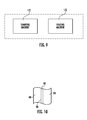
- FIG. 10 is an enlarged cross-sectional view of a portion of the cooling fin of FIG. 4 .
- the battery cell assembly 10 includes rectangular ring-shaped frame members 20 , 22 , battery cells 30 , 32 , and a cooling fin 40 .
- An advantage of the battery cell assembly 10 is that the assembly 10 utilizes a cooling fin 40 having a rectangular-shaped aluminum plate 80 with a flexible thermally conductive sheet 84 disposed thereon.
- the flexible thermally conductive sheet 84 having a relatively smooth surface which is disposed against an adjacent battery cell and eliminates abrasive rubbing against the battery cell by the rough surface.
- the flexible thermally conductive sheet 84 has excellent thermal characteristics for conducting heat energy from the battery cell to the aluminum plate 80 .
- the rectangular ring-shaped frame members 20 , 22 are configured to be coupled together to hold the battery cells 30 , 32 and the cooling fin 40 therebetween.
- the rectangular ring-shaped frame members 20 , 22 are constructed of plastic.
- the rectangular ring-shaped frame members 20 , 22 could be constructed of other materials known to those skilled in the art.
- the battery cells 30 , 32 are each configured to generate an operational voltage.
- each of the battery cells 30 , 32 are pouch-type lithium-ion battery cells.
- the battery cells 30 , 32 are electrically coupled in series to one another.
- the battery cell 30 includes a rectangular-shaped pouch 50 and electrodes 52 , 54 extending from the pouch 50 .
- the battery cell 30 is disposed between the rectangular ring-shaped frame member 20 and the cooling fin 40 .
- the battery cell 32 includes a rectangular-shaped pouch 60 , an electrode 62 and another electrode (not shown).
- the battery cell 32 is disposed between the rectangular ring-shaped frame member 22 and the cooling fin 40 .
- the cooling fin 40 is provided to transfer heat energy from the battery cells 30 , 32 to a refrigerant or a liquid flowing through the cooling fin 40 to cool the battery cells 30 , 32 .
- the cooling fin 40 includes a generally rectangular-shaped aluminum plate 80 , a tube 82 , and a flexible thermally conductive sheet 84 .
- the rectangular-shaped aluminum plate 80 has a first side 90 and a second side 92 .
- the plate 80 further includes first, second, third, and fourth peripheral edge portions 100 , 102 , 104 , 106 (shown in FIG. 5 ) that are each arcuate-shaped to hold a portion of the tube 82 thereon.
- the first, second, third, and fourth peripheral edge portions 100 , 102 , 104 , 106 define an arcuate-shaped groove 109 (shown in FIG. 6 ) configured to receive the tube 82 thereon.
- the tube 82 is coupled to the first side 90 of the generally rectangular-shaped aluminum plate 80 , and is coupled to and extends on the first, second, third, and fourth peripheral edge portions 100 , 102 , 104 , 106 of the plate 80 .
- the tube 82 is constructed of aluminum.
- the tube 82 could be constructed of other materials known to those skilled in the art.
- the tube 82 includes an inlet port 120 , tube portions 122 , 124 , 126 , 128 , 130 , and an outlet port 132 .
- the inlet port 120 is coupled to the tube portion 122 .
- the tube portion 122 is coupled between the inlet port 120 and the tube portion 124 .
- the tube portion 126 is coupled between the tube portion 124 and the tube portion 128 .
- the tube portion 130 is coupled between the tube portion 128 and the outlet port 132 .
- the tube portion 122 is coupled to the fourth peripheral edge portion 106
- the tube portion 124 is coupled to the first peripheral edge portion 100 , via brazing.
- the tube portion 126 is coupled to the second peripheral edge portion 102
- the tube portion 128 is coupled to the third peripheral edge portion 104 , via brazing.
- the tube portion 130 is coupled to the fourth peripheral edge portion 106 via brazing.
- the flexible thermally conductive sheet 84 is disposed on the first side 90 of the generally rectangular-shaped aluminum plate 80 .
- the flexible thermally conductive sheet 84 comprises a flexible sheet constructed at least in part utilizing graphite having a thickness in a range of 0.25-0.5 millimeters.
- the sheet 84 has an in-plane (e.g., planar with a surface of the sheet 84 contacting the plate 80 ) heat conductivity of greater than 200 Watts/meter—Kelvin.
- a side of the sheet 84 contacting the battery cell 30 has a roughness average (RA) in a range of 0.8-4.0 micro inches.
- RA roughness average
- the sheet 84 could have an RA less than 0.8 or greater than 4.0.
- the sheet 84 further includes a pressure sensitive adhesive 83 (shown in FIG. 10 ) disposed on one side of the sheet 84 that is used to attach the sheet 84 on the first side 90 of the plate 80 wherein the first side 90 has an abrasive brazing residue disposed thereon.
- the sheet 84 could be coupled to the plate 80 utilizing other coupling devices known to those skilled in the art.
- the sheet 84 is generally rectangular-shaped and is sized to cover substantially all of a generally rectangular-shaped side surface of the battery cell 30 .
- the sheet 84 could have other shapes and sizes known to those skilled in the art.
- the sheet 84 is configured to transfer heat energy from the battery cell 30 to the generally rectangular-shaped aluminum plate 80 .
- the plate 80 is configured to transfer at least a portion of the heat energy to the tube 82 .
- the sheet 80 could comprise “Spreadershield SS-400” manufactured by GrafTech International Holdings Inc.
- a refrigerant or a liquid enters the inlet port 120 from a source device and flows through the tube portions 122 , 124 , 126 , 128 , 130 to the outlet port 132 and exits the outlet port 132 to a receiving device.
- Heat energy generated by the battery cell 30 is conducted through the flexible thermally conductive sheet 84 and the rectangular-shaped aluminum plate 80 to the tube 82 .
- heat energy generated by the battery cell 32 is conducted through the rectangular-shaped aluminum plate 80 to the tube 82 .
- the heat energy in the tube 82 is conducted into the refrigerant or the liquid flowing through the tube 82 .
- the refrigerant or the liquid flowing through the tube 82 absorbs the heat energy from the battery cells 30 , 32 to reduce a temperature of the battery cell 30 , 32 .
- FIGS. 1 , 5 , 6 , 8 and 9 a flowchart of a method for manufacturing the cooling fin 40 utilizing a stamping machine 170 and a brazing machine 172 , in accordance with another exemplary embodiment will now be explained.
- an operator provides the generally rectangular-shaped aluminum plate 80 , the tube 82 , and the flexible thermally conductive sheet 84 .
- the generally rectangular-shaped aluminum plate 80 has the first side 90 and the second side 92 .
- the stamping machine 170 forms an arcuate-shaped groove 109 on the first, second, third, and fourth peripheral edge portions 100 , 102 , 104 , 106 of the generally rectangular-shaped aluminum plate 80 .
- the operator disposes the tube 82 in the arcuate-shaped groove 109 such that the tube 82 is disposed on the first, second, third, and fourth peripheral edge portions 100 , 102 , 104 , 106 of the generally rectangular-shaped aluminum plate 82 .
- the brazing machine 172 brazes the tube 82 to the first side 90 of the generally rectangular-shaped aluminum plate 80 such that the tube 82 is attached to the first, second, third, and fourth peripheral edge portions 100 , 102 , 104 , 106 of the generally rectangular-shaped aluminum plate 82 .
- the operator attaches the flexible thermally conductive sheet 84 on the first side 90 of the generally rectangular-shaped aluminum plate 80 .
- the battery cell assembly 10 and the method for manufacturing the cooling fin 40 provide a substantial advantage over other battery cell assemblies and methods.
- the battery cell assembly 10 and the method provide a technical effect of utilizing a cooling fin 40 with a flexible thermally conductive sheet 84 disposed on a relatively rough surface of the cooling fin 40 such that the flexible thermally conductive sheet 84 is disposed against the adjacent battery cell to prevent abrasive rubbing of the rough surface against the battery cell.
Abstract
Description
Claims (13)
Priority Applications (7)
| Application Number | Priority Date | Filing Date | Title |
|---|---|---|---|
| US13/475,963 US8852781B2 (en) | 2012-05-19 | 2012-05-19 | Battery cell assembly and method for manufacturing a cooling fin for the battery cell assembly |
| KR1020130018542A KR101415050B1 (en) | 2012-05-19 | 2013-02-21 | Battery Cell Assembly and Method for Manufacturing a Cooling fin for The Battery Cell Assembly |
| EP13793145.7A EP2840626B1 (en) | 2012-05-19 | 2013-05-08 | Battery cell assembly, and method for manufacturing cooling fin for battery cell assembly |
| CN201380026173.4A CN104335384B (en) | 2012-05-19 | 2013-05-08 | Battery cell assembly, and method for manufacturing cooling fin for battery cell assembly |
| JP2015513885A JP6066532B2 (en) | 2012-05-19 | 2013-05-08 | Battery cell assembly and method for manufacturing cooling fin for battery cell assembly |
| PCT/KR2013/004015 WO2013176424A1 (en) | 2012-05-19 | 2013-05-08 | Battery cell assembly, and method for manufacturing cooling fin for battery cell assembly |
| US14/488,349 US9461343B2 (en) | 2012-05-19 | 2014-09-17 | Battery cell assembly and method for manufacturing a cooling fin for the battery cell assembly |
Applications Claiming Priority (1)
| Application Number | Priority Date | Filing Date | Title |
|---|---|---|---|
| US13/475,963 US8852781B2 (en) | 2012-05-19 | 2012-05-19 | Battery cell assembly and method for manufacturing a cooling fin for the battery cell assembly |
Related Child Applications (1)
| Application Number | Title | Priority Date | Filing Date |
|---|---|---|---|
| US14/488,349 Division US9461343B2 (en) | 2012-05-19 | 2014-09-17 | Battery cell assembly and method for manufacturing a cooling fin for the battery cell assembly |
Publications (2)
| Publication Number | Publication Date |
|---|---|
| US20130309542A1 US20130309542A1 (en) | 2013-11-21 |
| US8852781B2 true US8852781B2 (en) | 2014-10-07 |
Family
ID=49581548
Family Applications (2)
| Application Number | Title | Priority Date | Filing Date |
|---|---|---|---|
| US13/475,963 Active 2033-02-05 US8852781B2 (en) | 2012-05-19 | 2012-05-19 | Battery cell assembly and method for manufacturing a cooling fin for the battery cell assembly |
| US14/488,349 Active 2032-12-04 US9461343B2 (en) | 2012-05-19 | 2014-09-17 | Battery cell assembly and method for manufacturing a cooling fin for the battery cell assembly |
Family Applications After (1)
| Application Number | Title | Priority Date | Filing Date |
|---|---|---|---|
| US14/488,349 Active 2032-12-04 US9461343B2 (en) | 2012-05-19 | 2014-09-17 | Battery cell assembly and method for manufacturing a cooling fin for the battery cell assembly |
Country Status (6)
| Country | Link |
|---|---|
| US (2) | US8852781B2 (en) |
| EP (1) | EP2840626B1 (en) |
| JP (1) | JP6066532B2 (en) |
| KR (1) | KR101415050B1 (en) |
| CN (1) | CN104335384B (en) |
| WO (1) | WO2013176424A1 (en) |
Cited By (6)
| Publication number | Priority date | Publication date | Assignee | Title |
|---|---|---|---|---|
| US20140120390A1 (en) * | 2012-10-31 | 2014-05-01 | Lg Chem, Ltd. | Battery cell assembly and method for manufacturing a cooling fin for the battery cell assembly |
| US10249920B2 (en) | 2015-05-26 | 2019-04-02 | Lg Chem, Ltd. | Battery cell assembly |
| USD855562S1 (en) | 2017-02-24 | 2019-08-06 | Ge Global Sourcing Llc | Battery module |
| US10637112B2 (en) | 2016-02-12 | 2020-04-28 | Lg Chem, Ltd. | Busbar for cooling battery cell and battery module using same |
| US10730460B2 (en) * | 2016-03-24 | 2020-08-04 | Volvo Truck Corporation | Vehicle cab body for a vehicle |
| US20220285753A1 (en) * | 2021-03-05 | 2022-09-08 | Bell Textron Inc. | Aircraft battery pack and associated cooling system |
Families Citing this family (33)
| Publication number | Priority date | Publication date | Assignee | Title |
|---|---|---|---|---|
| US9759495B2 (en) | 2008-06-30 | 2017-09-12 | Lg Chem, Ltd. | Battery cell assembly having heat exchanger with serpentine flow path |
| US20100275619A1 (en) * | 2009-04-30 | 2010-11-04 | Lg Chem, Ltd. | Cooling system for a battery system and a method for cooling the battery system |
| US9379420B2 (en) | 2012-03-29 | 2016-06-28 | Lg Chem, Ltd. | Battery system and method for cooling the battery system |
| US9605914B2 (en) | 2012-03-29 | 2017-03-28 | Lg Chem, Ltd. | Battery system and method of assembling the battery system |
| US9105950B2 (en) | 2012-03-29 | 2015-08-11 | Lg Chem, Ltd. | Battery system having an evaporative cooling member with a plate portion and a method for cooling the battery system |
| US8852781B2 (en) | 2012-05-19 | 2014-10-07 | Lg Chem, Ltd. | Battery cell assembly and method for manufacturing a cooling fin for the battery cell assembly |
| US9306199B2 (en) | 2012-08-16 | 2016-04-05 | Lg Chem, Ltd. | Battery module and method for assembling the battery module |
| US9083066B2 (en) | 2012-11-27 | 2015-07-14 | Lg Chem, Ltd. | Battery system and method for cooling a battery cell assembly |
| US8852783B2 (en) * | 2013-02-13 | 2014-10-07 | Lg Chem, Ltd. | Battery cell assembly and method for manufacturing the battery cell assembly |
| US9184424B2 (en) | 2013-07-08 | 2015-11-10 | Lg Chem, Ltd. | Battery assembly |
| US9444124B2 (en) | 2014-01-23 | 2016-09-13 | Lg Chem, Ltd. | Battery cell assembly and method for coupling a cooling fin to first and second cooling manifolds |
| KR102241333B1 (en) * | 2014-04-24 | 2021-04-16 | 에스케이이노베이션 주식회사 | Battery module for secondary battery |
| KR102210460B1 (en) * | 2014-04-24 | 2021-02-02 | 에스케이이노베이션 주식회사 | Battery cell assembly for secondary battery |
| US10084218B2 (en) | 2014-05-09 | 2018-09-25 | Lg Chem, Ltd. | Battery pack and method of assembling the battery pack |
| US10770762B2 (en) | 2014-05-09 | 2020-09-08 | Lg Chem, Ltd. | Battery module and method of assembling the battery module |
| KR101833526B1 (en) * | 2014-05-29 | 2018-02-28 | 주식회사 엘지화학 | Battery Module Having Water-Cooled Type Cooling Structure |
| KR102211192B1 (en) * | 2014-05-30 | 2021-02-02 | 에스케이이노베이션 주식회사 | Unit battery modue, Battery module and Battery pack And Method for manufacturing the same |
| US9484559B2 (en) | 2014-10-10 | 2016-11-01 | Lg Chem, Ltd. | Battery cell assembly |
| US9412980B2 (en) | 2014-10-17 | 2016-08-09 | Lg Chem, Ltd. | Battery cell assembly |
| US9786894B2 (en) | 2014-11-03 | 2017-10-10 | Lg Chem, Ltd. | Battery pack |
| US9627724B2 (en) | 2014-12-04 | 2017-04-18 | Lg Chem, Ltd. | Battery pack having a cooling plate assembly |
| KR101943489B1 (en) * | 2015-04-30 | 2019-01-29 | 주식회사 엘지화학 | Battery pack and method for manufacturing the same |
| DE102015214662A1 (en) * | 2015-07-31 | 2017-02-02 | Volkswagen Aktiengesellschaft | Traction battery with battery cell modules |
| KR102065102B1 (en) * | 2015-09-02 | 2020-01-10 | 주식회사 엘지화학 | A battery module having an improved cooling structure |
| KR102033064B1 (en) * | 2017-05-26 | 2019-10-16 | 엘티정밀(주) | A Manufacturing Method Of Battery Cooling Apparatus For Electric Behicle |
| FR3075336B1 (en) * | 2017-12-14 | 2020-02-07 | Valeo Systemes Thermiques | HEAT EXCHANGER FOR THERMAL MANAGEMENT OF AN ELECTRIC BATTERY |
| CN109560344A (en) * | 2018-02-07 | 2019-04-02 | 骆驼集团武汉光谷研发中心有限公司 | A kind of pressure-resisting flexible liquid-cooling heat radiation piece |
| KR101881990B1 (en) | 2018-07-02 | 2018-07-25 | 주식회사 티엔디 | For lithium-ion batteries type Cooling Plate Manufacturing Method and System, thats goods |
| KR102204302B1 (en) * | 2018-09-13 | 2021-01-15 | 주식회사 엘지화학 | Battery module, battery pack comprising the battery module and vehicle comprising the battery pack |
| KR20220038848A (en) * | 2020-09-21 | 2022-03-29 | 주식회사 엘지에너지솔루션 | Battery Module With Improved Cooling Performance And Battery Pack Including It |
| IT202100005102A1 (en) * | 2021-03-04 | 2022-09-04 | Dynamic Tech S P A | COOLER |
| IT202100005117A1 (en) * | 2021-03-04 | 2022-09-04 | Dynamic Tech S P A | COOLER |
| CN114571194B (en) * | 2022-04-11 | 2024-03-15 | 山东裕航特种合金装备有限公司 | Processing method and processing tool for whole hole site of battery tray of new energy automobile |
Citations (165)
| Publication number | Priority date | Publication date | Assignee | Title |
|---|---|---|---|---|
| US1587425A (en) | 1923-06-18 | 1926-06-01 | Schepp Otto | Cooling accumulator cell |
| GB481891A (en) | 1936-09-18 | 1938-03-18 | India Rubber Gutta Percha Tele | Improvements in or relating to containers for electric storage cells |
| US2273244A (en) | 1940-04-03 | 1942-02-17 | Electric Storage Battery Co | Storage battery cell |
| US2391859A (en) | 1931-11-07 | 1946-01-01 | Hoover Co | Room cooling device |
| US3503558A (en) | 1968-03-14 | 1970-03-31 | Electrolux Corp | Exhaust diffusion manifold for a vacuum cleaner or the like |
| US3522100A (en) | 1966-12-19 | 1970-07-28 | Asea Ab | Fuel cell battery |
| US3550681A (en) | 1968-12-30 | 1970-12-29 | Gen Motors Corp | Self-adjusting thermal connector |
| US3964930A (en) | 1975-07-21 | 1976-06-22 | United Technologies Corporation | Fuel cell cooling system |
| US4009752A (en) | 1975-02-24 | 1977-03-01 | Honeywell Information Systems Inc. | Warp-resistant heat sink |
| US4063590A (en) | 1976-10-22 | 1977-12-20 | Mcconnell Christopher L | Preheater for clothes dryer |
| US4298904A (en) | 1979-12-17 | 1981-11-03 | The Boeing Company | Electronic conduction cooling clamp |
| US4305456A (en) | 1977-08-12 | 1981-12-15 | Paul Mueller Company | Condenser and hot water system |
| US4322776A (en) | 1980-08-04 | 1982-03-30 | Hughes Aircraft Company | Thermal interconnection |
| US4444994A (en) | 1982-01-29 | 1984-04-24 | Varo, Inc. | Electrically insulated quick disconnect heat sink |
| US4518663A (en) | 1983-07-01 | 1985-05-21 | Energy Development Associates, Inc. | Electrolyte circulation subsystem |
| US4646202A (en) | 1983-11-02 | 1987-02-24 | British Aerospace Plc | Cabinet for electronic apparatus |
| US4701829A (en) | 1985-04-16 | 1987-10-20 | Amphenol Corporation | Thermal connector for printed circuit card equipped with electronic components |
| US4777561A (en) | 1985-03-26 | 1988-10-11 | Hughes Aircraft Company | Electronic module with self-activated heat pipe |
| US4849858A (en) | 1986-10-20 | 1989-07-18 | Westinghouse Electric Corp. | Composite heat transfer means |
| US4982785A (en) | 1990-03-06 | 1991-01-08 | Inter-City Products Corporation (Usa) | Serpentine heat exchanger |
| US4995240A (en) | 1987-01-27 | 1991-02-26 | Eaton Corporation | Controlling refrigeration having control module directly attached on valve body |
| US5057968A (en) | 1989-10-16 | 1991-10-15 | Lockheed Corporation | Cooling system for electronic modules |
| US5071652A (en) | 1990-12-11 | 1991-12-10 | Globe-Union Inc. | Metal oxide hydrogen battery having improved heat transfer properties |
| US5186250A (en) | 1990-05-11 | 1993-02-16 | Showa Aluminum Kabushiki Kaisha | Tube for heat exchangers and a method for manufacturing the tube |
| US5214564A (en) | 1992-04-23 | 1993-05-25 | Sunstrand Corporation | Capacitor assembly with integral cooling apparatus |
| US5270131A (en) | 1990-12-11 | 1993-12-14 | Sulzer Brothers Limited | Module for a fuel cell battery |
| US5322745A (en) | 1992-11-10 | 1994-06-21 | Matsushita Electric Industrial Co., Ltd. | Storage battery system |
| US5329988A (en) | 1993-05-28 | 1994-07-19 | The Allen Group, Inc. | Heat exchanger |
| US5346786A (en) | 1994-03-21 | 1994-09-13 | Hodgetts Philip J | Modular rack mounted battery system |
| US5356735A (en) | 1993-05-10 | 1994-10-18 | General Motors Corporation | Heated/cooled battery |
| US5443926A (en) | 1992-11-02 | 1995-08-22 | Compagnie Europeenne D'accumulateurs | Thermoregulated battery of accumulators, especially for an electric vehicle |
| US5510203A (en) | 1994-02-23 | 1996-04-23 | Matsushita Electric Industrial Co., Ltd. | Cell and module battery of sealed alkaline storage battery |
| JPH08111244A (en) | 1994-10-12 | 1996-04-30 | Nissan Motor Co Ltd | Layer-built battery device |
| US5520976A (en) | 1993-06-30 | 1996-05-28 | Simmonds Precision Products Inc. | Composite enclosure for electronic hardware |
| JPH09129213A (en) | 1995-11-06 | 1997-05-16 | Toshiba Battery Co Ltd | Manufacture of battery |
| JPH09219213A (en) | 1996-02-09 | 1997-08-19 | Nissan Motor Co Ltd | Secondary battery for electric vehicle and temperature rise alleviation device therefor |
| US5663007A (en) | 1994-02-23 | 1997-09-02 | Matsushita Electric Industrial Co., Ltd. | Sealed storage battery and method for manufacturing the same |
| US5731568A (en) * | 1995-10-13 | 1998-03-24 | Arctic Fox, Inc. | Battery heating device and method |
| US5736836A (en) | 1996-04-10 | 1998-04-07 | Honda Giken Kogyo Kabushiki Kaisha | Battery discharge gas control system |
| US5756227A (en) | 1994-11-18 | 1998-05-26 | Honda Giken Kogyo Kabushiki Kaisha | Battery assembly with temperature control mechanism |
| US5937664A (en) | 1997-03-05 | 1999-08-17 | Toyota Jidosha Kabushiki Kaisha | Battery cooling system for vehicle |
| US5985483A (en) | 1998-01-29 | 1999-11-16 | Alcatel | Sealed battery block provided with a cooling system |
| US6087036A (en) | 1997-07-25 | 2000-07-11 | 3M Innovative Properties Company | Thermal management system and method for a solid-state energy storing device |
| US6111387A (en) | 1997-03-24 | 2000-08-29 | Matsushita Electric Industrial Co., Ltd. | End plate incorporated in battery power source unit, and cooling device for same |
| US6176095B1 (en) | 1999-01-19 | 2001-01-23 | Carrier Corporation | Pretrip device for testing of a refrigeration system compressor |
| JP2001105843A (en) | 1999-10-12 | 2001-04-17 | Nippon Soken Inc | Battery cooling device |
| US6289979B1 (en) | 1997-12-08 | 2001-09-18 | Zexel Corporation | Heat exchanger |
| US6344728B1 (en) | 1997-10-06 | 2002-02-05 | Matsushita Electric Industrial Co., Ltd. | Battery power source supply with coolant flow |
| JP2002038033A (en) | 2000-05-19 | 2002-02-06 | Suzuki Sogyo Co Ltd | Thermally conductive sheet |
| US6362598B2 (en) | 2000-04-29 | 2002-03-26 | Vb Autobatterie Gmbh | Method for determining the state of charge and loading capacity of an electrical storage battery |
| US6399238B1 (en) | 1999-12-13 | 2002-06-04 | Alcatel | Module configuration |
| US6422027B1 (en) | 2001-05-03 | 2002-07-23 | Ford Global Tech., Inc. | System and method for cooling a battery pack |
| US6448741B1 (en) | 1998-09-03 | 2002-09-10 | Matsushita Electric Industrial Co., Ltd. | Temperature control method and structure for a battery pack |
| US6462949B1 (en) | 2000-08-07 | 2002-10-08 | Thermotek, Inc. | Electronic enclosure cooling system |
| JP2002319383A (en) | 2001-04-23 | 2002-10-31 | Toyota Motor Corp | Battery module |
| JP2002333255A (en) | 2002-03-29 | 2002-11-22 | Sanyo Electric Co Ltd | Cryogenic refrigerator |
| US20020182493A1 (en) | 1993-10-25 | 2002-12-05 | Ovshinsky Stanford R. | Mechanical and thermal improvements in metal hydride batteries, battery modules and battery packs |
| US6512347B1 (en) | 2001-10-18 | 2003-01-28 | General Motors Corporation | Battery having an integral cooling system |
| US20030080714A1 (en) | 2001-10-29 | 2003-05-01 | Yoshimitsu Inoue | Battery temperature control device for controlling the temperature of battery installed in vehicle |
| US20030094263A1 (en) * | 2000-05-09 | 2003-05-22 | Marconi Communications, Inc. | Apparatus for cooling a battery in an outdoor equipment cabinet |
| US6569556B2 (en) | 2001-01-29 | 2003-05-27 | General Motors Corporation | Cooling system for a battery pack |
| JP2003188323A (en) | 2001-12-19 | 2003-07-04 | Sony Corp | Graphite sheet and its manufacturing method |
| DE19639115C2 (en) | 1996-09-24 | 2003-08-07 | Behr Gmbh & Co | Plate-shaped heat transfer element |
| JP2003282112A (en) | 2002-03-26 | 2003-10-03 | Denso Corp | Intermediate heat exchanger for fuel cell |
| US20030211384A1 (en) | 2002-05-13 | 2003-11-13 | Matsushita Electric Industrial Co., Ltd. | Cooling device for battery pack and rechargeable battery |
| US6662891B2 (en) | 2000-04-13 | 2003-12-16 | Toyota Jidosha Kabushiki Kaisha | Vehicle power source device wherein cooling air is introduced into battery casing through opening formed through vehicle floor |
| US6689510B1 (en) | 1998-08-23 | 2004-02-10 | Ovonic Battery Company, Inc. | Monoblock battery assembly with cross-flow cooling |
| US6696197B2 (en) | 2000-09-29 | 2004-02-24 | Kabushiki Kaisha Toshiba | Battery pack and portable electronic appliance |
| US6703160B2 (en) * | 2000-04-13 | 2004-03-09 | Fmc Corporation, Lithium Division | Battery pack or battery providing increased heat dissipation |
| US20040069474A1 (en) | 2002-07-05 | 2004-04-15 | Alan Wu | Baffled surface cooled heat exchanger |
| US6724172B2 (en) | 2002-06-26 | 2004-04-20 | Hyundai Motor Company | Method for determining a maximum charge current and a maximum discharge current of a battery |
| US6775998B2 (en) | 2000-11-10 | 2004-08-17 | Matsushita Refrigeration Company | Freezer and refrigerator provided with freezer |
| US6780538B2 (en) | 1999-07-22 | 2004-08-24 | Matsushita Electric Industrial Co., Ltd. | Battery module, and rechargeable battery for constituting the battery module |
| US6821671B2 (en) | 2002-03-01 | 2004-11-23 | Lg Chem, Ltd. | Method and apparatus for cooling and positioning prismatic battery cells |
| JP2004333115A (en) | 2003-04-16 | 2004-11-25 | Showa Denko Kk | Heat exchanger, and method for manufacturing the same |
| US6826948B1 (en) | 2003-10-09 | 2004-12-07 | Delphi Technologies, Inc. | Leak detection apparatus for a liquid circulation cooling system |
| US20050026014A1 (en) | 2003-07-31 | 2005-02-03 | Michael Fogaing | Polymer batteries having thermal exchange apparatus |
| US20050089750A1 (en) | 2002-02-19 | 2005-04-28 | Chin-Yee Ng | Temperature control apparatus and method for high energy electrochemical cells |
| JP2005126315A (en) | 2003-09-30 | 2005-05-19 | Hitachi Ltd | Hydrogen storage and supply device, its system, and distributed power and car using the same |
| US20050103486A1 (en) | 2001-12-21 | 2005-05-19 | Behr Gmbh & Co., Kg | Heat exchanger, particularly for a motor vehicle |
| US20050110460A1 (en) | 2003-10-21 | 2005-05-26 | Juichi Arai | Battery module having lithium battery, and vehicle control system employing battery module having lithium battery |
| JP2005147443A (en) | 2003-11-12 | 2005-06-09 | Calsonic Kansei Corp | Laminated type heat exchanger |
| US20050134038A1 (en) | 2003-12-17 | 2005-06-23 | Eaton Corporation | Fitting for fluid conveyance |
| KR20050092605A (en) | 2004-03-16 | 2005-09-22 | 주식회사 엘지화학 | Secondary battery having a high safety |
| JP2005349955A (en) | 2004-06-10 | 2005-12-22 | Toyota Motor Corp | Cooling structure for power storage mechanism |
| US6982131B1 (en) | 1999-10-08 | 2006-01-03 | Matsushita Electric Industrial Co., Ltd. | Structure for electrode terminals of battery module |
| JP2006139928A (en) | 2004-11-10 | 2006-06-01 | Nissan Motor Co Ltd | Battery system |
| US7070874B2 (en) | 2002-12-24 | 2006-07-04 | Fuelcell Energy, Inc. | Fuel cell end unit with integrated heat exchanger |
| WO2006101343A1 (en) | 2005-03-23 | 2006-09-28 | Sk Energy Co., Ltd. | Structure of layering unit cells for high power lithium polymer battery |
| US20060234119A1 (en) | 2005-04-14 | 2006-10-19 | Kruger Duane D | Apparatus and method for securing battery cell packs |
| KR100637472B1 (en) | 2004-12-07 | 2006-10-23 | 삼성에스디아이 주식회사 | Secondary battery module |
| US7143124B2 (en) | 2002-12-06 | 2006-11-28 | Sun Microsystems, Inc. | Detection of dead regions during incremental collection |
| US20060286450A1 (en) | 2005-06-03 | 2006-12-21 | Junill Yoon | Secondary battery of novel structure and battery pack having the same |
| WO2007007503A1 (en) | 2005-07-12 | 2007-01-18 | Toyota Jidosha Kabushiki Kaisha | Structure of hybrid vehicle |
| US20070062681A1 (en) | 2005-09-19 | 2007-03-22 | Stephen Beech | Flanged connection for heat exchanger |
| US20070087266A1 (en) | 2005-10-18 | 2007-04-19 | Debbi Bourke | Modular battery system |
| US7250741B2 (en) | 2003-08-13 | 2007-07-31 | Hyundai Motor Company | Method and system for calculating available power of a battery |
| US7264902B2 (en) | 2001-07-04 | 2007-09-04 | Nissan Motor Co., Ltd. | Battery system with excellent controllability for temperature |
| US20070227166A1 (en) | 2003-12-22 | 2007-10-04 | General Electric Company | Methods and apparatus for controlling refrigerators |
| US7278389B2 (en) | 2005-04-19 | 2007-10-09 | Murat Kirakosyan | Automobile intake air flow plenum and plenum diverter |
| KR100765659B1 (en) | 2005-08-09 | 2007-10-10 | 현대자동차주식회사 | Fuel cell-stack structure for automobile |
| WO2007115743A2 (en) | 2006-04-04 | 2007-10-18 | Daimler Ag | Heat exchanger comprising deep-drawn, integrally formed distribution and collecting channels for heat-exchanger module plates comprising a tempering medium |
| EP1852925A1 (en) | 2005-02-25 | 2007-11-07 | Toyota Jidosha Kabushiki Kaisha | Battery pack |
| JP2007305425A (en) | 2006-05-11 | 2007-11-22 | Toyota Motor Corp | Battery pack and vehicle |
| US20080003491A1 (en) | 2003-10-03 | 2008-01-03 | Yahnker Christopher R | Thermal management systems for battery packs |
| US20080041079A1 (en) | 2006-06-26 | 2008-02-21 | Denso Corporation | Refrigerant cycle device with ejector |
| JP2008054379A (en) | 2006-08-22 | 2008-03-06 | Calsonic Kansei Corp | Battery cooling system for vehicle |
| JP2008062875A (en) | 2006-09-11 | 2008-03-21 | Calsonic Kansei Corp | Battery cooling system for vehicle |
| JP2008080995A (en) | 2006-09-28 | 2008-04-10 | Denso Corp | Cooling system |
| US20080110189A1 (en) | 2006-11-15 | 2008-05-15 | Glacier Bay. Inc. | Hvac system |
| KR20080047641A (en) | 2006-11-27 | 2008-05-30 | 주식회사 엘지화학 | Power supply system having heat radiation-preventing structure |
| JP2008159440A (en) | 2006-12-25 | 2008-07-10 | Calsonic Kansei Corp | Vehicular battery cooling system |
| US20080182151A1 (en) | 2007-01-25 | 2008-07-31 | Honda Motor Co., Ltd. | Fuel cell system |
| WO2008111162A1 (en) | 2007-03-13 | 2008-09-18 | Hoshizaki Denki Kabushiki Kaisha | Cooling storage chamber and method for operating the same |
| US20080248338A1 (en) | 2004-10-05 | 2008-10-09 | Masaya Yano | Fuel Cell and Power Generating Method |
| US20080299446A1 (en) | 2007-06-01 | 2008-12-04 | Cobasys. Llc | Coolant manifold |
| US7467525B1 (en) | 2005-08-23 | 2008-12-23 | Denso Corporation | Supercritical refrigeration cycle system |
| JP2009009889A (en) | 2007-06-29 | 2009-01-15 | Sanyo Electric Co Ltd | Power source device for vehicle |
| JP2009054297A (en) | 2007-08-23 | 2009-03-12 | Toshiba Corp | Battery pack |
| US20090074478A1 (en) | 2007-06-19 | 2009-03-19 | Konica Minolta Business Technologies, Inc. | Resin composition, molded component, electrophotographic transfer film and image-forming apparatus |
| US20090104512A1 (en) | 2007-01-30 | 2009-04-23 | Jochen Fassnacht | Device having at least one electrochemical cell |
| US7531270B2 (en) | 2006-10-13 | 2009-05-12 | Enerdel, Inc. | Battery pack with integral cooling and bussing devices |
| WO2009073225A1 (en) | 2007-12-05 | 2009-06-11 | Enerdel, Inc. | Battery assembly with temperature control device |
| US20090155680A1 (en) | 2005-03-16 | 2009-06-18 | Ford Global Technologies, Llc | Power supply system |
| US20090186265A1 (en) | 2008-01-18 | 2009-07-23 | Lg Chem, Ltd | Battery cell assembly and method for assembling the battery cell assembly |
| KR100921346B1 (en) | 2006-09-25 | 2009-10-13 | 주식회사 엘지화학 | Mid-Large Battery Module and Battery Module Assembly |
| KR20090107443A (en) | 2008-04-08 | 2009-10-13 | 쏘씨에떼 드 베이뀔르 엘렉트리끄 | Electrical battery comprising flexible generating elements and a system for the mechanical and thermal conditioning of said elements |
| US20090258289A1 (en) | 2008-04-09 | 2009-10-15 | Gm Global Technology Operations, Inc. | Battery cooling plate design with discrete channels |
| US20090258288A1 (en) | 2008-04-09 | 2009-10-15 | Gm Global Technology Operations, Inc. | Batteries and components thereof and methods of making and assembling the same |
| US20090280395A1 (en) | 2008-05-09 | 2009-11-12 | Gm Global Technology Operations, Inc. | Battery Thermal System for Vehicle |
| US20090325052A1 (en) | 2008-06-30 | 2009-12-31 | Lg Chem, Ltd. | Battery Module Having Cooling Manifold and Method for Cooling Battery Module |
| US20090325054A1 (en) | 2008-06-30 | 2009-12-31 | Lg Chem, Ltd. | Battery Cell Assembly Having Heat Exchanger With Serpentine Flow Path |
| US20090325055A1 (en) | 2008-06-30 | 2009-12-31 | Lg Chem, Ltd. | Battery module having cooling manifold with ported screws and method for cooling the battery module |
| US20090325051A1 (en) | 2008-06-30 | 2009-12-31 | Lg Chem, Ltd. | Battery Module Having a Rubber Cooling Manifold |
| US20100112419A1 (en) | 2007-04-04 | 2010-05-06 | Soo Yeup Jang | Battery temperature controller for electric vehicle using thermoelectric semiconductor |
| US20100203376A1 (en) | 2007-03-21 | 2010-08-12 | Lg Chem, Ltd. | Middle or large-sized battery pack case providing improved distribution uniformity in coolant flux |
| US20100209760A1 (en) | 2007-05-10 | 2010-08-19 | Calsonic Kansei Corporation | Battery-cell module structure of battery |
| US7795845B2 (en) | 2005-03-25 | 2010-09-14 | Samsung Sdi Co., Ltd. | Rechargeable battery module having a cooling mechanism |
| US20100262791A1 (en) | 2002-08-29 | 2010-10-14 | Gilton Terry L | Software refreshed memory device and method |
| US7816029B2 (en) | 2006-08-31 | 2010-10-19 | Nissan Motor Co., Ltd. | Battery module |
| US20100279152A1 (en) | 2009-04-30 | 2010-11-04 | Lg Chem, Ltd. | Battery systems, battery modules, and method for cooling a battery module |
| US20100276132A1 (en) | 2009-04-30 | 2010-11-04 | Lg Chem, Ltd. | Cooling manifold and method for manufacturing the cooling manifold |
| US20100279154A1 (en) | 2009-04-30 | 2010-11-04 | Lg Chem, Ltd. | Battery systems, battery modules, and method for cooling a battery module |
| US20100275619A1 (en) | 2009-04-30 | 2010-11-04 | Lg Chem, Ltd. | Cooling system for a battery system and a method for cooling the battery system |
| EP2262048A1 (en) | 2008-03-24 | 2010-12-15 | Sanyo Electric Co., Ltd. | Battery device and battery unit |
| US7879480B2 (en) | 2004-12-24 | 2011-02-01 | Lg Chem, Ltd. | Battery cartridge for novel structure and open type battery module containing the same |
| US20110027640A1 (en) | 2009-07-29 | 2011-02-03 | Lg Chem, Ltd. | Battery module and method for cooling the battery module |
| US7883793B2 (en) | 2008-06-30 | 2011-02-08 | Lg Chem, Ltd. | Battery module having battery cell assemblies with alignment-coupling features |
| KR20110013270A (en) | 2009-07-29 | 2011-02-09 | 주식회사 엘지화학 | Battery module and method for cooling the battery module |
| US20110041525A1 (en) | 2007-11-05 | 2011-02-24 | Lg Electronics Inc. | Control method of refrigerator |
| US20110045326A1 (en) | 2008-02-27 | 2011-02-24 | Stephan Leuthner | Device and method for cooling a battery module |
| US20110052959A1 (en) | 2009-08-28 | 2011-03-03 | Lg Chem, Ltd. | Battery module and method for cooling the battery module |
| US7976978B2 (en) | 2006-10-23 | 2011-07-12 | Lg Chem, Ltd. | Member of connecting electrode in battery module |
| US7981538B2 (en) | 2005-08-10 | 2011-07-19 | Samsung Sdi Co., Ltd. | Battery module with improved cell barrier between unit cells |
| EP1577966A3 (en) | 2004-03-18 | 2011-09-28 | Fuji Jukogyo Kabushiki Kaisha | Accumulator device |
| US8030886B2 (en) | 2005-12-21 | 2011-10-04 | Nuventix, Inc. | Thermal management of batteries using synthetic jets |
| KR20110126764A (en) | 2010-05-18 | 2011-11-24 | 주식회사 엘지화학 | Cooling member of compact structure and excellent stability and battery module employed with the same |
| US8067111B2 (en) | 2008-06-30 | 2011-11-29 | Lg Chem, Ltd. | Battery module having battery cell assembly with heat exchanger |
| US20120082880A1 (en) | 2010-10-04 | 2012-04-05 | Lg Chem Ltd. | Battery cell assembly, heat exchanger, and method for manufacturing the heat exchanger |
| US8409743B2 (en) | 2007-11-28 | 2013-04-02 | Sanyo Electric Co., Ltd. | Battery system with battery cells arranged in array alignment |
| US20130255293A1 (en) | 2012-03-29 | 2013-10-03 | Lg Chem, Ltd. | Battery system and method for cooling the battery system |
| US20130309542A1 (en) | 2012-05-19 | 2013-11-21 | Lg Chem, Ltd. | Battery cell assembly and method for manufacturing a cooling fin for the battery cell assembly |
| US20140050966A1 (en) | 2012-08-16 | 2014-02-20 | Lg Chem, Ltd. | Battery module and method for assembling the battery module |
| US20140050953A1 (en) | 2012-08-16 | 2014-02-20 | Lg Chem, Ltd. | Battery module |
| US20140147709A1 (en) | 2012-11-27 | 2014-05-29 | Satish Ketkar | Battery system and method for cooling a battery cell assembly |
Family Cites Families (13)
| Publication number | Priority date | Publication date | Assignee | Title |
|---|---|---|---|---|
| US6117584A (en) * | 1997-07-25 | 2000-09-12 | 3M Innovative Properties Company | Thermal conductor for high-energy electrochemical cells |
| JP2004361022A (en) * | 2003-06-05 | 2004-12-24 | Denso Corp | Heat exchanger |
| JP3963165B2 (en) * | 2003-10-10 | 2007-08-22 | 日産自動車株式会社 | Assembled battery |
| JP5159425B2 (en) * | 2008-05-19 | 2013-03-06 | 古河電池株式会社 | Battery module |
| US20110053052A1 (en) * | 2009-08-28 | 2011-03-03 | Enerfuel, Inc. | Fuel cell composite flow field element and method of forming the same |
| US11152669B2 (en) * | 2009-11-09 | 2021-10-19 | Enerdel, Inc. | Scalable battery module |
| US9780421B2 (en) * | 2010-02-02 | 2017-10-03 | Dana Canada Corporation | Conformal heat exchanger for battery cell stack |
| KR101205181B1 (en) * | 2010-05-18 | 2012-11-27 | 주식회사 엘지화학 | Cooling Member of Novel Structure and Battery Module Employed with the Same |
| US8673473B2 (en) * | 2010-08-10 | 2014-03-18 | GM Global Technology Operations LLC | Integrated cooling fin and frame |
| US8574740B2 (en) * | 2010-08-10 | 2013-11-05 | GM Global Technology Operations LLC | Molded frame with corrugated cooling fin for air-cooled battery |
| CN103069644B (en) * | 2010-08-16 | 2016-01-27 | 株式会社Lg化学 | There is the battery module of compact structure and good heat radiating characteristic and adopt the medium-and-large-sized battery pack of this battery module |
| JP2012204129A (en) * | 2011-03-25 | 2012-10-22 | Hitachi Maxell Ltd | Battery pack |
| KR101305403B1 (en) * | 2011-12-30 | 2013-09-05 | 대한칼소닉주식회사 | Method of welding heat insulating board for secondary battery and secondary battery cell of zig assembly for heat insulating board |
-
2012
- 2012-05-19 US US13/475,963 patent/US8852781B2/en active Active
-
2013
- 2013-02-21 KR KR1020130018542A patent/KR101415050B1/en active IP Right Grant
- 2013-05-08 JP JP2015513885A patent/JP6066532B2/en active Active
- 2013-05-08 WO PCT/KR2013/004015 patent/WO2013176424A1/en active Application Filing
- 2013-05-08 CN CN201380026173.4A patent/CN104335384B/en active Active
- 2013-05-08 EP EP13793145.7A patent/EP2840626B1/en active Active
-
2014
- 2014-09-17 US US14/488,349 patent/US9461343B2/en active Active
Patent Citations (181)
| Publication number | Priority date | Publication date | Assignee | Title |
|---|---|---|---|---|
| US1587425A (en) | 1923-06-18 | 1926-06-01 | Schepp Otto | Cooling accumulator cell |
| US2391859A (en) | 1931-11-07 | 1946-01-01 | Hoover Co | Room cooling device |
| GB481891A (en) | 1936-09-18 | 1938-03-18 | India Rubber Gutta Percha Tele | Improvements in or relating to containers for electric storage cells |
| US2273244A (en) | 1940-04-03 | 1942-02-17 | Electric Storage Battery Co | Storage battery cell |
| US3522100A (en) | 1966-12-19 | 1970-07-28 | Asea Ab | Fuel cell battery |
| US3503558A (en) | 1968-03-14 | 1970-03-31 | Electrolux Corp | Exhaust diffusion manifold for a vacuum cleaner or the like |
| US3550681A (en) | 1968-12-30 | 1970-12-29 | Gen Motors Corp | Self-adjusting thermal connector |
| US4009752A (en) | 1975-02-24 | 1977-03-01 | Honeywell Information Systems Inc. | Warp-resistant heat sink |
| US3964930A (en) | 1975-07-21 | 1976-06-22 | United Technologies Corporation | Fuel cell cooling system |
| US4063590A (en) | 1976-10-22 | 1977-12-20 | Mcconnell Christopher L | Preheater for clothes dryer |
| US4305456A (en) | 1977-08-12 | 1981-12-15 | Paul Mueller Company | Condenser and hot water system |
| US4298904A (en) | 1979-12-17 | 1981-11-03 | The Boeing Company | Electronic conduction cooling clamp |
| US4322776A (en) | 1980-08-04 | 1982-03-30 | Hughes Aircraft Company | Thermal interconnection |
| US4444994A (en) | 1982-01-29 | 1984-04-24 | Varo, Inc. | Electrically insulated quick disconnect heat sink |
| US4518663A (en) | 1983-07-01 | 1985-05-21 | Energy Development Associates, Inc. | Electrolyte circulation subsystem |
| US4646202A (en) | 1983-11-02 | 1987-02-24 | British Aerospace Plc | Cabinet for electronic apparatus |
| US4777561A (en) | 1985-03-26 | 1988-10-11 | Hughes Aircraft Company | Electronic module with self-activated heat pipe |
| US4701829A (en) | 1985-04-16 | 1987-10-20 | Amphenol Corporation | Thermal connector for printed circuit card equipped with electronic components |
| US4849858A (en) | 1986-10-20 | 1989-07-18 | Westinghouse Electric Corp. | Composite heat transfer means |
| US4995240A (en) | 1987-01-27 | 1991-02-26 | Eaton Corporation | Controlling refrigeration having control module directly attached on valve body |
| US5057968A (en) | 1989-10-16 | 1991-10-15 | Lockheed Corporation | Cooling system for electronic modules |
| US4982785A (en) | 1990-03-06 | 1991-01-08 | Inter-City Products Corporation (Usa) | Serpentine heat exchanger |
| US5186250A (en) | 1990-05-11 | 1993-02-16 | Showa Aluminum Kabushiki Kaisha | Tube for heat exchangers and a method for manufacturing the tube |
| US5071652A (en) | 1990-12-11 | 1991-12-10 | Globe-Union Inc. | Metal oxide hydrogen battery having improved heat transfer properties |
| US5270131A (en) | 1990-12-11 | 1993-12-14 | Sulzer Brothers Limited | Module for a fuel cell battery |
| US5214564A (en) | 1992-04-23 | 1993-05-25 | Sunstrand Corporation | Capacitor assembly with integral cooling apparatus |
| US5443926A (en) | 1992-11-02 | 1995-08-22 | Compagnie Europeenne D'accumulateurs | Thermoregulated battery of accumulators, especially for an electric vehicle |
| US5322745A (en) | 1992-11-10 | 1994-06-21 | Matsushita Electric Industrial Co., Ltd. | Storage battery system |
| US5356735A (en) | 1993-05-10 | 1994-10-18 | General Motors Corporation | Heated/cooled battery |
| US5329988A (en) | 1993-05-28 | 1994-07-19 | The Allen Group, Inc. | Heat exchanger |
| US5520976A (en) | 1993-06-30 | 1996-05-28 | Simmonds Precision Products Inc. | Composite enclosure for electronic hardware |
| US20020182493A1 (en) | 1993-10-25 | 2002-12-05 | Ovshinsky Stanford R. | Mechanical and thermal improvements in metal hydride batteries, battery modules and battery packs |
| US6878485B2 (en) | 1993-10-25 | 2005-04-12 | Ovonic Battery Company, Inc. | Mechanical and thermal improvements in metal hydride batteries, battery modules and battery packs |
| US5510203A (en) | 1994-02-23 | 1996-04-23 | Matsushita Electric Industrial Co., Ltd. | Cell and module battery of sealed alkaline storage battery |
| US5663007A (en) | 1994-02-23 | 1997-09-02 | Matsushita Electric Industrial Co., Ltd. | Sealed storage battery and method for manufacturing the same |
| US5346786A (en) | 1994-03-21 | 1994-09-13 | Hodgetts Philip J | Modular rack mounted battery system |
| JPH08111244A (en) | 1994-10-12 | 1996-04-30 | Nissan Motor Co Ltd | Layer-built battery device |
| US5756227A (en) | 1994-11-18 | 1998-05-26 | Honda Giken Kogyo Kabushiki Kaisha | Battery assembly with temperature control mechanism |
| US5731568A (en) * | 1995-10-13 | 1998-03-24 | Arctic Fox, Inc. | Battery heating device and method |
| JPH09129213A (en) | 1995-11-06 | 1997-05-16 | Toshiba Battery Co Ltd | Manufacture of battery |
| JPH09219213A (en) | 1996-02-09 | 1997-08-19 | Nissan Motor Co Ltd | Secondary battery for electric vehicle and temperature rise alleviation device therefor |
| US5736836A (en) | 1996-04-10 | 1998-04-07 | Honda Giken Kogyo Kabushiki Kaisha | Battery discharge gas control system |
| DE19639115C2 (en) | 1996-09-24 | 2003-08-07 | Behr Gmbh & Co | Plate-shaped heat transfer element |
| US5937664A (en) | 1997-03-05 | 1999-08-17 | Toyota Jidosha Kabushiki Kaisha | Battery cooling system for vehicle |
| US6111387A (en) | 1997-03-24 | 2000-08-29 | Matsushita Electric Industrial Co., Ltd. | End plate incorporated in battery power source unit, and cooling device for same |
| US6087036A (en) | 1997-07-25 | 2000-07-11 | 3M Innovative Properties Company | Thermal management system and method for a solid-state energy storing device |
| US6344728B1 (en) | 1997-10-06 | 2002-02-05 | Matsushita Electric Industrial Co., Ltd. | Battery power source supply with coolant flow |
| US6289979B1 (en) | 1997-12-08 | 2001-09-18 | Zexel Corporation | Heat exchanger |
| US5985483A (en) | 1998-01-29 | 1999-11-16 | Alcatel | Sealed battery block provided with a cooling system |
| US6689510B1 (en) | 1998-08-23 | 2004-02-10 | Ovonic Battery Company, Inc. | Monoblock battery assembly with cross-flow cooling |
| US6448741B1 (en) | 1998-09-03 | 2002-09-10 | Matsushita Electric Industrial Co., Ltd. | Temperature control method and structure for a battery pack |
| US6176095B1 (en) | 1999-01-19 | 2001-01-23 | Carrier Corporation | Pretrip device for testing of a refrigeration system compressor |
| US6780538B2 (en) | 1999-07-22 | 2004-08-24 | Matsushita Electric Industrial Co., Ltd. | Battery module, and rechargeable battery for constituting the battery module |
| US6982131B1 (en) | 1999-10-08 | 2006-01-03 | Matsushita Electric Industrial Co., Ltd. | Structure for electrode terminals of battery module |
| JP2001105843A (en) | 1999-10-12 | 2001-04-17 | Nippon Soken Inc | Battery cooling device |
| US6399238B1 (en) | 1999-12-13 | 2002-06-04 | Alcatel | Module configuration |
| US6703160B2 (en) * | 2000-04-13 | 2004-03-09 | Fmc Corporation, Lithium Division | Battery pack or battery providing increased heat dissipation |
| US6662891B2 (en) | 2000-04-13 | 2003-12-16 | Toyota Jidosha Kabushiki Kaisha | Vehicle power source device wherein cooling air is introduced into battery casing through opening formed through vehicle floor |
| US6362598B2 (en) | 2000-04-29 | 2002-03-26 | Vb Autobatterie Gmbh | Method for determining the state of charge and loading capacity of an electrical storage battery |
| US20030094263A1 (en) * | 2000-05-09 | 2003-05-22 | Marconi Communications, Inc. | Apparatus for cooling a battery in an outdoor equipment cabinet |
| JP2002038033A (en) | 2000-05-19 | 2002-02-06 | Suzuki Sogyo Co Ltd | Thermally conductive sheet |
| US6462949B1 (en) | 2000-08-07 | 2002-10-08 | Thermotek, Inc. | Electronic enclosure cooling system |
| US6696197B2 (en) | 2000-09-29 | 2004-02-24 | Kabushiki Kaisha Toshiba | Battery pack and portable electronic appliance |
| US6775998B2 (en) | 2000-11-10 | 2004-08-17 | Matsushita Refrigeration Company | Freezer and refrigerator provided with freezer |
| US6569556B2 (en) | 2001-01-29 | 2003-05-27 | General Motors Corporation | Cooling system for a battery pack |
| JP2002319383A (en) | 2001-04-23 | 2002-10-31 | Toyota Motor Corp | Battery module |
| US6422027B1 (en) | 2001-05-03 | 2002-07-23 | Ford Global Tech., Inc. | System and method for cooling a battery pack |
| US7264902B2 (en) | 2001-07-04 | 2007-09-04 | Nissan Motor Co., Ltd. | Battery system with excellent controllability for temperature |
| US6512347B1 (en) | 2001-10-18 | 2003-01-28 | General Motors Corporation | Battery having an integral cooling system |
| US6750630B2 (en) | 2001-10-29 | 2004-06-15 | Denso Corporation | Battery temperature control device for controlling the temperature of a battery installed in vehicle which includes an air passage to the battery from a rear air-conditioning unit |
| US20030080714A1 (en) | 2001-10-29 | 2003-05-01 | Yoshimitsu Inoue | Battery temperature control device for controlling the temperature of battery installed in vehicle |
| JP2003188323A (en) | 2001-12-19 | 2003-07-04 | Sony Corp | Graphite sheet and its manufacturing method |
| US20050103486A1 (en) | 2001-12-21 | 2005-05-19 | Behr Gmbh & Co., Kg | Heat exchanger, particularly for a motor vehicle |
| US20050089750A1 (en) | 2002-02-19 | 2005-04-28 | Chin-Yee Ng | Temperature control apparatus and method for high energy electrochemical cells |
| US6821671B2 (en) | 2002-03-01 | 2004-11-23 | Lg Chem, Ltd. | Method and apparatus for cooling and positioning prismatic battery cells |
| JP2003282112A (en) | 2002-03-26 | 2003-10-03 | Denso Corp | Intermediate heat exchanger for fuel cell |
| JP2002333255A (en) | 2002-03-29 | 2002-11-22 | Sanyo Electric Co Ltd | Cryogenic refrigerator |
| US7150935B2 (en) | 2002-05-13 | 2006-12-19 | Matsushita Electric Industrial Co., Ltd | Cooling device for battery pack and rechargeable battery |
| US20030211384A1 (en) | 2002-05-13 | 2003-11-13 | Matsushita Electric Industrial Co., Ltd. | Cooling device for battery pack and rechargeable battery |
| US6724172B2 (en) | 2002-06-26 | 2004-04-20 | Hyundai Motor Company | Method for determining a maximum charge current and a maximum discharge current of a battery |
| US20040069474A1 (en) | 2002-07-05 | 2004-04-15 | Alan Wu | Baffled surface cooled heat exchanger |
| US20100262791A1 (en) | 2002-08-29 | 2010-10-14 | Gilton Terry L | Software refreshed memory device and method |
| US7143124B2 (en) | 2002-12-06 | 2006-11-28 | Sun Microsystems, Inc. | Detection of dead regions during incremental collection |
| US7070874B2 (en) | 2002-12-24 | 2006-07-04 | Fuelcell Energy, Inc. | Fuel cell end unit with integrated heat exchanger |
| JP2004333115A (en) | 2003-04-16 | 2004-11-25 | Showa Denko Kk | Heat exchanger, and method for manufacturing the same |
| US20050026014A1 (en) | 2003-07-31 | 2005-02-03 | Michael Fogaing | Polymer batteries having thermal exchange apparatus |
| US7250741B2 (en) | 2003-08-13 | 2007-07-31 | Hyundai Motor Company | Method and system for calculating available power of a battery |
| JP2005126315A (en) | 2003-09-30 | 2005-05-19 | Hitachi Ltd | Hydrogen storage and supply device, its system, and distributed power and car using the same |
| US20080003491A1 (en) | 2003-10-03 | 2008-01-03 | Yahnker Christopher R | Thermal management systems for battery packs |
| US6826948B1 (en) | 2003-10-09 | 2004-12-07 | Delphi Technologies, Inc. | Leak detection apparatus for a liquid circulation cooling system |
| US20050110460A1 (en) | 2003-10-21 | 2005-05-26 | Juichi Arai | Battery module having lithium battery, and vehicle control system employing battery module having lithium battery |
| JP2005147443A (en) | 2003-11-12 | 2005-06-09 | Calsonic Kansei Corp | Laminated type heat exchanger |
| US20050134038A1 (en) | 2003-12-17 | 2005-06-23 | Eaton Corporation | Fitting for fluid conveyance |
| US20070227166A1 (en) | 2003-12-22 | 2007-10-04 | General Electric Company | Methods and apparatus for controlling refrigerators |
| KR20050092605A (en) | 2004-03-16 | 2005-09-22 | 주식회사 엘지화학 | Secondary battery having a high safety |
| EP1577966A3 (en) | 2004-03-18 | 2011-09-28 | Fuji Jukogyo Kabushiki Kaisha | Accumulator device |
| JP2005349955A (en) | 2004-06-10 | 2005-12-22 | Toyota Motor Corp | Cooling structure for power storage mechanism |
| US20080248338A1 (en) | 2004-10-05 | 2008-10-09 | Masaya Yano | Fuel Cell and Power Generating Method |
| JP2006139928A (en) | 2004-11-10 | 2006-06-01 | Nissan Motor Co Ltd | Battery system |
| KR100637472B1 (en) | 2004-12-07 | 2006-10-23 | 삼성에스디아이 주식회사 | Secondary battery module |
| US7879480B2 (en) | 2004-12-24 | 2011-02-01 | Lg Chem, Ltd. | Battery cartridge for novel structure and open type battery module containing the same |
| EP1852925A1 (en) | 2005-02-25 | 2007-11-07 | Toyota Jidosha Kabushiki Kaisha | Battery pack |
| US20090155680A1 (en) | 2005-03-16 | 2009-06-18 | Ford Global Technologies, Llc | Power supply system |
| WO2006101343A1 (en) | 2005-03-23 | 2006-09-28 | Sk Energy Co., Ltd. | Structure of layering unit cells for high power lithium polymer battery |
| US7795845B2 (en) | 2005-03-25 | 2010-09-14 | Samsung Sdi Co., Ltd. | Rechargeable battery module having a cooling mechanism |
| US20060234119A1 (en) | 2005-04-14 | 2006-10-19 | Kruger Duane D | Apparatus and method for securing battery cell packs |
| US7278389B2 (en) | 2005-04-19 | 2007-10-09 | Murat Kirakosyan | Automobile intake air flow plenum and plenum diverter |
| US20060286450A1 (en) | 2005-06-03 | 2006-12-21 | Junill Yoon | Secondary battery of novel structure and battery pack having the same |
| WO2007007503A1 (en) | 2005-07-12 | 2007-01-18 | Toyota Jidosha Kabushiki Kaisha | Structure of hybrid vehicle |
| KR100765659B1 (en) | 2005-08-09 | 2007-10-10 | 현대자동차주식회사 | Fuel cell-stack structure for automobile |
| US7981538B2 (en) | 2005-08-10 | 2011-07-19 | Samsung Sdi Co., Ltd. | Battery module with improved cell barrier between unit cells |
| US20080314071A1 (en) | 2005-08-23 | 2008-12-25 | Denso Corporation | Supercritical refrigeration cycle system |
| US7467525B1 (en) | 2005-08-23 | 2008-12-23 | Denso Corporation | Supercritical refrigeration cycle system |
| US20070062681A1 (en) | 2005-09-19 | 2007-03-22 | Stephen Beech | Flanged connection for heat exchanger |
| US20070087266A1 (en) | 2005-10-18 | 2007-04-19 | Debbi Bourke | Modular battery system |
| US8030886B2 (en) | 2005-12-21 | 2011-10-04 | Nuventix, Inc. | Thermal management of batteries using synthetic jets |
| WO2007115743A2 (en) | 2006-04-04 | 2007-10-18 | Daimler Ag | Heat exchanger comprising deep-drawn, integrally formed distribution and collecting channels for heat-exchanger module plates comprising a tempering medium |
| JP2007305425A (en) | 2006-05-11 | 2007-11-22 | Toyota Motor Corp | Battery pack and vehicle |
| US7997367B2 (en) | 2006-05-11 | 2011-08-16 | Toyota Jidosha Kabushiki Kaisha | Assembled battery and vehicle |
| US20080041079A1 (en) | 2006-06-26 | 2008-02-21 | Denso Corporation | Refrigerant cycle device with ejector |
| JP2008054379A (en) | 2006-08-22 | 2008-03-06 | Calsonic Kansei Corp | Battery cooling system for vehicle |
| US7816029B2 (en) | 2006-08-31 | 2010-10-19 | Nissan Motor Co., Ltd. | Battery module |
| JP2008062875A (en) | 2006-09-11 | 2008-03-21 | Calsonic Kansei Corp | Battery cooling system for vehicle |
| KR100921346B1 (en) | 2006-09-25 | 2009-10-13 | 주식회사 엘지화학 | Mid-Large Battery Module and Battery Module Assembly |
| JP2008080995A (en) | 2006-09-28 | 2008-04-10 | Denso Corp | Cooling system |
| KR20090082212A (en) | 2006-10-13 | 2009-07-29 | 에네르델, 인코포레이티드 | Battery assembly with temperature control device |
| US7531270B2 (en) | 2006-10-13 | 2009-05-12 | Enerdel, Inc. | Battery pack with integral cooling and bussing devices |
| US7976978B2 (en) | 2006-10-23 | 2011-07-12 | Lg Chem, Ltd. | Member of connecting electrode in battery module |
| US7797958B2 (en) | 2006-11-15 | 2010-09-21 | Glacier Bay, Inc. | HVAC system controlled by a battery management system |
| US20080110189A1 (en) | 2006-11-15 | 2008-05-15 | Glacier Bay. Inc. | Hvac system |
| KR20080047641A (en) | 2006-11-27 | 2008-05-30 | 주식회사 엘지화학 | Power supply system having heat radiation-preventing structure |
| JP2008159440A (en) | 2006-12-25 | 2008-07-10 | Calsonic Kansei Corp | Vehicular battery cooling system |
| US20080182151A1 (en) | 2007-01-25 | 2008-07-31 | Honda Motor Co., Ltd. | Fuel cell system |
| US20090104512A1 (en) | 2007-01-30 | 2009-04-23 | Jochen Fassnacht | Device having at least one electrochemical cell |
| US8209991B2 (en) | 2007-03-13 | 2012-07-03 | Hoshizaki Denki Kabushiki Kaisha | Cooling storage and method of operating the same |
| WO2008111162A1 (en) | 2007-03-13 | 2008-09-18 | Hoshizaki Denki Kabushiki Kaisha | Cooling storage chamber and method for operating the same |
| US20100203376A1 (en) | 2007-03-21 | 2010-08-12 | Lg Chem, Ltd. | Middle or large-sized battery pack case providing improved distribution uniformity in coolant flux |
| US20100112419A1 (en) | 2007-04-04 | 2010-05-06 | Soo Yeup Jang | Battery temperature controller for electric vehicle using thermoelectric semiconductor |
| US20100209760A1 (en) | 2007-05-10 | 2010-08-19 | Calsonic Kansei Corporation | Battery-cell module structure of battery |
| US7846573B2 (en) | 2007-06-01 | 2010-12-07 | Cobasys, Llc | Coolant manifold |
| US20080299446A1 (en) | 2007-06-01 | 2008-12-04 | Cobasys. Llc | Coolant manifold |
| US8007915B2 (en) | 2007-06-19 | 2011-08-30 | Konica Minolta Business Technoloigies, Inc. | Resin composition, molded component, electrophotographic transfer film and image-forming apparatus |
| US20090074478A1 (en) | 2007-06-19 | 2009-03-19 | Konica Minolta Business Technologies, Inc. | Resin composition, molded component, electrophotographic transfer film and image-forming apparatus |
| JP2009009889A (en) | 2007-06-29 | 2009-01-15 | Sanyo Electric Co Ltd | Power source device for vehicle |
| JP2009054297A (en) | 2007-08-23 | 2009-03-12 | Toshiba Corp | Battery pack |
| US20090087727A1 (en) | 2007-08-23 | 2009-04-02 | Kabushiki Kaisha Toshiba | Battery pack |
| US20110041525A1 (en) | 2007-11-05 | 2011-02-24 | Lg Electronics Inc. | Control method of refrigerator |
| US8409743B2 (en) | 2007-11-28 | 2013-04-02 | Sanyo Electric Co., Ltd. | Battery system with battery cells arranged in array alignment |
| WO2009073225A1 (en) | 2007-12-05 | 2009-06-11 | Enerdel, Inc. | Battery assembly with temperature control device |
| US20090186265A1 (en) | 2008-01-18 | 2009-07-23 | Lg Chem, Ltd | Battery cell assembly and method for assembling the battery cell assembly |
| US20110045326A1 (en) | 2008-02-27 | 2011-02-24 | Stephan Leuthner | Device and method for cooling a battery module |
| EP2262048A1 (en) | 2008-03-24 | 2010-12-15 | Sanyo Electric Co., Ltd. | Battery device and battery unit |
| KR20090107443A (en) | 2008-04-08 | 2009-10-13 | 쏘씨에떼 드 베이뀔르 엘렉트리끄 | Electrical battery comprising flexible generating elements and a system for the mechanical and thermal conditioning of said elements |
| US20090258289A1 (en) | 2008-04-09 | 2009-10-15 | Gm Global Technology Operations, Inc. | Battery cooling plate design with discrete channels |
| US20090258288A1 (en) | 2008-04-09 | 2009-10-15 | Gm Global Technology Operations, Inc. | Batteries and components thereof and methods of making and assembling the same |
| US20090280395A1 (en) | 2008-05-09 | 2009-11-12 | Gm Global Technology Operations, Inc. | Battery Thermal System for Vehicle |
| US7883793B2 (en) | 2008-06-30 | 2011-02-08 | Lg Chem, Ltd. | Battery module having battery cell assemblies with alignment-coupling features |
| US8067111B2 (en) | 2008-06-30 | 2011-11-29 | Lg Chem, Ltd. | Battery module having battery cell assembly with heat exchanger |
| US20090325052A1 (en) | 2008-06-30 | 2009-12-31 | Lg Chem, Ltd. | Battery Module Having Cooling Manifold and Method for Cooling Battery Module |
| US20090325054A1 (en) | 2008-06-30 | 2009-12-31 | Lg Chem, Ltd. | Battery Cell Assembly Having Heat Exchanger With Serpentine Flow Path |
| US20090325055A1 (en) | 2008-06-30 | 2009-12-31 | Lg Chem, Ltd. | Battery module having cooling manifold with ported screws and method for cooling the battery module |
| US20090325051A1 (en) | 2008-06-30 | 2009-12-31 | Lg Chem, Ltd. | Battery Module Having a Rubber Cooling Manifold |
| US20100276132A1 (en) | 2009-04-30 | 2010-11-04 | Lg Chem, Ltd. | Cooling manifold and method for manufacturing the cooling manifold |
| US20100279152A1 (en) | 2009-04-30 | 2010-11-04 | Lg Chem, Ltd. | Battery systems, battery modules, and method for cooling a battery module |
| KR20100119498A (en) | 2009-04-30 | 2010-11-09 | 주식회사 엘지화학 | Battery systems, battery modules, and method for cooling a battery module |
| KR20100119497A (en) | 2009-04-30 | 2010-11-09 | 주식회사 엘지화학 | Cooling system for a battery system and a method for cooling the battery system |
| US20100275619A1 (en) | 2009-04-30 | 2010-11-04 | Lg Chem, Ltd. | Cooling system for a battery system and a method for cooling the battery system |
| US20100279154A1 (en) | 2009-04-30 | 2010-11-04 | Lg Chem, Ltd. | Battery systems, battery modules, and method for cooling a battery module |
| KR20110013269A (en) | 2009-07-29 | 2011-02-09 | 주식회사 엘지화학 | Battery module and method for cooling the battery module |
| US20110027640A1 (en) | 2009-07-29 | 2011-02-03 | Lg Chem, Ltd. | Battery module and method for cooling the battery module |
| KR20110013270A (en) | 2009-07-29 | 2011-02-09 | 주식회사 엘지화학 | Battery module and method for cooling the battery module |
| US20110052959A1 (en) | 2009-08-28 | 2011-03-03 | Lg Chem, Ltd. | Battery module and method for cooling the battery module |
| WO2011145830A2 (en) * | 2010-05-18 | 2011-11-24 | 주식회사 엘지화학 | Compact cooling member having superior stability, and battery module comprising same |
| US20130045410A1 (en) * | 2010-05-18 | 2013-02-21 | Lg Chem. Ltd. | Cooling member of compact structure and excellent stability and battery module employed with the same |
| KR20110126764A (en) | 2010-05-18 | 2011-11-24 | 주식회사 엘지화학 | Cooling member of compact structure and excellent stability and battery module employed with the same |
| US20120082880A1 (en) | 2010-10-04 | 2012-04-05 | Lg Chem Ltd. | Battery cell assembly, heat exchanger, and method for manufacturing the heat exchanger |
| US20130255293A1 (en) | 2012-03-29 | 2013-10-03 | Lg Chem, Ltd. | Battery system and method for cooling the battery system |
| US20130309542A1 (en) | 2012-05-19 | 2013-11-21 | Lg Chem, Ltd. | Battery cell assembly and method for manufacturing a cooling fin for the battery cell assembly |
| US20140050966A1 (en) | 2012-08-16 | 2014-02-20 | Lg Chem, Ltd. | Battery module and method for assembling the battery module |
| US20140050953A1 (en) | 2012-08-16 | 2014-02-20 | Lg Chem, Ltd. | Battery module |
| US20140147709A1 (en) | 2012-11-27 | 2014-05-29 | Satish Ketkar | Battery system and method for cooling a battery cell assembly |
Non-Patent Citations (31)
| Title |
|---|
| "Gasket". Merriam-Webster. Merriam-Webster. Web. May 30, 2012. . |
| "Gasket". Merriam-Webster. Merriam-Webster. Web. May 30, 2012. <http://www.merriam-webster.com/dictionary/gasket>. |
| International Search Report for International application No. PCT/KR2013/004015 dated Sep. 26, 2013. |
| International Search Report; International Application No. PCT/KR2009/000258; International Filing Date: Jan. 16, 2009; Date of Mailing: Aug. 28, 2009; 2 pages. |
| International Search Report; International Application No. PCT/KR2009/003428, International Filing Date: Jun. 25, 2009; Date of Mailing: Jan. 22, 2010; 2 pages. |
| International Search Report; International Application No. PCT/KR2009/003429; International Filing Date: Jun. 25, 2009; Date of Mailing: Jan. 12, 2010; 3 pages. |
| International Search Report; International Application No. PCT/KR2009/003430; International Filing Date: Jun. 25, 2009; Date of Mailing: Feb. 3, 2010; 2 pages. |
| International Search Report; International Application No. PCT/KR2009/003434; International Filing Date: Jun. 25, 2009; Date of Mailing: Jan. 18, 2010; 2 pages. |
| International Search Report; International Application No. PCT/KR2009/003436; International Filing Date: Jun. 25, 2009; Date of Mailing: Jan. 22, 2010; 2 pages. |
| International Search Report; International Application No. PCT/KR2009/006121; International Filing Date: Oct. 22, 2009; Date of Mailing: May 3, 2010; 2 pages. |
| International Search Report; International Application No. PCT/KR2010/002334; International Filing Date: Apr. 15, 2010; Date of Mailing: Nov. 29, 2010; 2 pages. |
| International Search Report; International Application No. PCT/KR2010/002336; International Filing Date: Apr. 15, 2010; Date of Mailing: Jan. 31, 2011; 2 pages. |
| International Search Report; International Application No. PCT/KR2010/002337; International Filing Date: Apr. 15, 2010; Date of Mailing: May 3, 2010; 2 pages. |
| International Search Report; International Application No. PCT/KR2010/002340; International Filing Date: Apr. 15, 2010; Date of Mailing: Jan. 31, 2011; 2 pages. |
| International Search Report; International Application No. PCT/KR2010/004944; International Filing Date: Jul. 28, 2010; Date of Mailing: Apr. 29, 2011; 2 pages. |
| International Search Report; International Application No. PCT/KR2010/005639; International Filing Date: Aug. 24, 2010; Date of Mailing: Jun. 3, 2011; 2 pages. |
| Machine translation of Japanese Patent Application No. 2009-009889 A, published Jan. 15, 2009. |
| Thomas J. Gadawski et al., pending U.S. Appl. No. 13/433,649 entitled "Battery System and Method for Cooling the Battery System," filed with the U.S. Patent and Trademark Office on Mar. 29, 2012. |
| U.S. Appl. No. 13/586,960, filed Aug. 16, 2012 entitled Battery Module. |
| U.S. Appl. No. 13/587,030, filed Aug. 16, 2012 entitled Battery Module and Method for Assembling the Battery Module. |
| U.S. Appl. No. 13/686,018, filed Nov. 27, 2012 entitled Battery System and Method for Cooling a Battery Cell Assembly. |
| U.S. Appl. No. 13/766,162, filed Feb. 13, 2013 entitled Battery Cell Assembly and Method for Manufacturing the Battery Cell Assembly. |
| U.S. Appl. No. 13/861,426, filed Apr. 12, 2013 entitled Battery Cell Assembly and Method for Manufacturing a Cooling Fin for the Battery Cell Assembly. |
| U.S. Appl. No. 13/936,556, filed Jul. 8, 2013 entitled Battery Assembly. |
| U.S. Appl. No. 14/059,547, filed Oct. 22, 2013 entitled Battery Cell Assembly. |
| U.S. Appl. No. 14/161,806, filed Jan. 23, 2014 entitled Battery Cell Assembly and Method for Coupling a Cooling Fin to First and Second Cooling Manifolds. |
| U.S. Appl. No. 14/273,572, filed May 9, 2014 entitled Battery Pack and Method of Assembling the Battery Pack. |
| U.S. Appl. No. 14/273,586, filed May 9, 2014 entitled Battery Module and Method of Assembling the Battery Module. |
| U.S. Appl. No. 14/328,000, filed Jul. 10, 2014 entitled Battery System and Method of Cooling the Battery System. |
| U.S. Appl. No. 14/330,163, filed Jul. 14, 2014 entitled Battery System and Method for Cooling the Battery System. |
| Written Opinion for International application No. PCT/KR2014/002090 dated May 26, 2014. |
Cited By (9)
| Publication number | Priority date | Publication date | Assignee | Title |
|---|---|---|---|---|
| US20140120390A1 (en) * | 2012-10-31 | 2014-05-01 | Lg Chem, Ltd. | Battery cell assembly and method for manufacturing a cooling fin for the battery cell assembly |
| US10249920B2 (en) | 2015-05-26 | 2019-04-02 | Lg Chem, Ltd. | Battery cell assembly |
| US10637112B2 (en) | 2016-02-12 | 2020-04-28 | Lg Chem, Ltd. | Busbar for cooling battery cell and battery module using same |
| US10730460B2 (en) * | 2016-03-24 | 2020-08-04 | Volvo Truck Corporation | Vehicle cab body for a vehicle |
| USD855562S1 (en) | 2017-02-24 | 2019-08-06 | Ge Global Sourcing Llc | Battery module |
| USD919561S1 (en) | 2017-02-24 | 2021-05-18 | Transportation Ip Holdings, Llc | Battery module |
| USD953254S1 (en) | 2017-02-24 | 2022-05-31 | Transportation Ip Holdings, Llc | Battery module |
| USD1007414S1 (en) | 2017-02-24 | 2023-12-12 | Transportation Ip Holdings, Llc | Battery module |
| US20220285753A1 (en) * | 2021-03-05 | 2022-09-08 | Bell Textron Inc. | Aircraft battery pack and associated cooling system |
Also Published As
| Publication number | Publication date |
|---|---|
| KR101415050B1 (en) | 2014-07-21 |
| US20130309542A1 (en) | 2013-11-21 |
| CN104335384B (en) | 2017-03-22 |
| JP2015522911A (en) | 2015-08-06 |
| KR20130129076A (en) | 2013-11-27 |
| JP6066532B2 (en) | 2017-01-25 |
| CN104335384A (en) | 2015-02-04 |
| US9461343B2 (en) | 2016-10-04 |
| EP2840626A4 (en) | 2015-05-20 |
| EP2840626A1 (en) | 2015-02-25 |
| US20150000134A1 (en) | 2015-01-01 |
| WO2013176424A1 (en) | 2013-11-28 |
| EP2840626B1 (en) | 2017-02-22 |
Similar Documents
| Publication | Publication Date | Title |
|---|---|---|
| US8852781B2 (en) | Battery cell assembly and method for manufacturing a cooling fin for the battery cell assembly | |
| US9647292B2 (en) | Battery cell assembly and method for manufacturing a cooling fin for the battery cell assembly | |
| EP2916382B1 (en) | Battery cell assembly and method for manufacturing cooling fin for battery cell assembly | |
| US8852783B2 (en) | Battery cell assembly and method for manufacturing the battery cell assembly | |
| US8399119B2 (en) | Battery module and method for cooling the battery module | |
| US20150207187A1 (en) | Battery cell assembly and method for coupling a cooling fin to first and second cooling manifolds | |
| US9257732B2 (en) | Battery cell assembly | |
| US20180248238A1 (en) | Graphene enhanced cooling fin | |
| JP2016040770A (en) | Heat exchange plate for temperature management of battery pack | |
| KR20160067711A (en) | Battery Pack | |
| US9605914B2 (en) | Battery system and method of assembling the battery system | |
| US10084217B2 (en) | Battery system | |
| JP6994303B2 (en) | Heat transfer device for assembled batteries | |
| US20180212289A1 (en) | Graphene enhanced cooling fin | |
| JP2017506424A (en) | Battery module | |
| US9865906B2 (en) | Battery system and method of assembling the battery system | |
| US9742044B2 (en) | Battery cell | |
| KR102068274B1 (en) | Battery cell assembly | |
| JP2014204045A (en) | Cooler |
Legal Events
| Date | Code | Title | Description |
|---|---|---|---|
| AS | Assignment |
Owner name: LG CHEM, LTD., KOREA, REPUBLIC OF Free format text: ASSIGNMENT OF ASSIGNORS INTEREST;ASSIGNORS:MERRIMAN, ROBERT;NIELSON, MICHAEL;ISAYEV, IGOR;AND OTHERS;SIGNING DATES FROM 20120502 TO 20120508;REEL/FRAME:028237/0533 |
|
| FEPP | Fee payment procedure |
Free format text: PAYOR NUMBER ASSIGNED (ORIGINAL EVENT CODE: ASPN); ENTITY STATUS OF PATENT OWNER: LARGE ENTITY |
|
| STCF | Information on status: patent grant |
Free format text: PATENTED CASE |
|
| MAFP | Maintenance fee payment |
Free format text: PAYMENT OF MAINTENANCE FEE, 4TH YEAR, LARGE ENTITY (ORIGINAL EVENT CODE: M1551) Year of fee payment: 4 |
|
| AS | Assignment |
Owner name: LG ENERGY SOLUTION, LTD., KOREA, REPUBLIC OF Free format text: ASSIGNMENT OF ASSIGNORS INTEREST;ASSIGNOR:LG CHEM, LTD.;REEL/FRAME:058295/0068 Effective date: 20211027 |
|
| MAFP | Maintenance fee payment |
Free format text: PAYMENT OF MAINTENANCE FEE, 8TH YEAR, LARGE ENTITY (ORIGINAL EVENT CODE: M1552); ENTITY STATUS OF PATENT OWNER: LARGE ENTITY Year of fee payment: 8 |