US8417004B2 - System and method for simulated linearization of curved surface - Google Patents
System and method for simulated linearization of curved surface Download PDFInfo
- Publication number
- US8417004B2 US8417004B2 US13/081,895 US201113081895A US8417004B2 US 8417004 B2 US8417004 B2 US 8417004B2 US 201113081895 A US201113081895 A US 201113081895A US 8417004 B2 US8417004 B2 US 8417004B2
- Authority
- US
- United States
- Prior art keywords
- image
- ellipse
- circle
- intermediate image
- radius
- Prior art date
- Legal status (The legal status is an assumption and is not a legal conclusion. Google has not performed a legal analysis and makes no representation as to the accuracy of the status listed.)
- Active, expires
Links
- 238000000034 method Methods 0.000 title claims abstract description 36
- 230000001131 transforming effect Effects 0.000 claims abstract description 14
- 238000013507 mapping Methods 0.000 claims abstract description 12
- 210000004373 mandible Anatomy 0.000 claims description 25
- 210000002050 maxilla Anatomy 0.000 claims description 10
- 238000004519 manufacturing process Methods 0.000 claims description 8
- 210000001519 tissue Anatomy 0.000 description 30
- 210000004872 soft tissue Anatomy 0.000 description 28
- 230000004044 response Effects 0.000 description 13
- 230000001815 facial effect Effects 0.000 description 11
- 230000009466 transformation Effects 0.000 description 11
- 238000003384 imaging method Methods 0.000 description 7
- 238000004088 simulation Methods 0.000 description 6
- 238000001356 surgical procedure Methods 0.000 description 6
- 238000012217 deletion Methods 0.000 description 5
- 230000037430 deletion Effects 0.000 description 5
- 230000006870 function Effects 0.000 description 5
- 230000009471 action Effects 0.000 description 4
- 210000003484 anatomy Anatomy 0.000 description 4
- 210000000988 bone and bone Anatomy 0.000 description 4
- 238000013459 approach Methods 0.000 description 3
- 238000004140 cleaning Methods 0.000 description 3
- 230000000694 effects Effects 0.000 description 3
- 230000002452 interceptive effect Effects 0.000 description 3
- 230000006378 damage Effects 0.000 description 2
- 230000007547 defect Effects 0.000 description 2
- 238000010586 diagram Methods 0.000 description 2
- 201000010099 disease Diseases 0.000 description 2
- 208000037265 diseases, disorders, signs and symptoms Diseases 0.000 description 2
- 238000011282 treatment Methods 0.000 description 2
- 241000282412 Homo Species 0.000 description 1
- 230000004075 alteration Effects 0.000 description 1
- 238000004364 calculation method Methods 0.000 description 1
- 238000002059 diagnostic imaging Methods 0.000 description 1
- 210000001847 jaw Anatomy 0.000 description 1
- 230000003287 optical effect Effects 0.000 description 1
- 238000012545 processing Methods 0.000 description 1
- 238000002601 radiography Methods 0.000 description 1
- 239000007787 solid Substances 0.000 description 1
- 238000001228 spectrum Methods 0.000 description 1
- 238000003860 storage Methods 0.000 description 1
- 238000006467 substitution reaction Methods 0.000 description 1
- 238000013519 translation Methods 0.000 description 1
Images


Classifications
-
- G06T3/06—
-
- G—PHYSICS
- G06—COMPUTING; CALCULATING OR COUNTING
- G06T—IMAGE DATA PROCESSING OR GENERATION, IN GENERAL
- G06T19/00—Manipulating 3D models or images for computer graphics
-
- G—PHYSICS
- G06—COMPUTING; CALCULATING OR COUNTING
- G06T—IMAGE DATA PROCESSING OR GENERATION, IN GENERAL
- G06T2219/00—Indexing scheme for manipulating 3D models or images for computer graphics
- G06T2219/021—Flattening
Definitions
- the present disclosure relates in general to dentofacial imaging, and more particularly to systems and methods for surgical planning using dentofacial imaging.
- Dentofacial surgery also referred to as oral and maxillofacial surgery
- oral and maxillofacial surgery is often employed to correct a wide spectrum of diseases, injuries and defects in the head, neck, face, jaws and the hard and soft tissues of the oral and maxillofacial region of humans or other non-human patients.
- practitioners of dentofacial surgery increasingly use computer-aided dentofacial imaging tools in order to model dentofacial features of patients, diagnose diseases, injuries, and defects, plan dentofacial surgical procedures and other treatments, and educate patients regarding diagnoses and treatments.
- a practitioner may, with the aid of a computer-aided tool, virtually modify various bones or bone segments of the patient via a user interface of a computer.
- Such computer-aided planning and simulation may allow a practitioner to simulate effect of various surgical adjustments on a patient, including effects on a patient's aesthetic appearance.
- traditional computer-aided surgical planning and simulation tools have significant disadvantages. For example, digital images of a patient's facial tissues generated by imaging devices may include undesirable noise and other artifacts. Thus, many traditional planning and simulation tools allow a practitioner to perform “cleaning” of a digital image to remove noise from the image.
- a method may include displaying one or more interactive two-dimensional images, each two-dimensional image representing at least bony tissue cranio-facial features of a patient and each two-dimensional image having one or more portions each associated with a corresponding portion of the patient's bony tissue such that a user may, via a user input device, cause movement of at least one of the one or more portions of such two-dimensional image to simulate movement of the corresponding portion of the patient's bony tissue in an osteotomy procedure.
- the method may also include displaying a three-dimensional image representing exterior soft-tissue cranio-facial features of the patient.
- the method may additionally include receiving input from a user regarding movement of a particular portion of the one or more portions of the two-dimensional image.
- the method may further include redrawing the three-dimensional image based at least on the movement of the particular portion of the two-dimensional image to simulate response of the exterior soft-tissue cranio-facial features of the patient to movement of a portion of the patient's bony tissue corresponding to the particular portion of the two-dimensional image.
- an article of manufacture may include a non-transitory computer-readable medium and computer-executable instructions carried on the computer-readable medium, the instructions executable by one or more processors and configured to cause the one or more processors to: (i) display one or more interactive two-dimensional images, each two-dimensional image representing at least bony tissue cranio-facial features of a patient and each two-dimensional image having one or more portions each associated with a corresponding portion of the patient's bony tissue such that a user may, via a user input device, cause movement of at least one of the one or more portions of such two-dimensional image to simulate movement of the corresponding portion of the patient's bony tissue in an osteotomy procedure; (ii) display a three-dimensional image representing exterior soft-tissue cranio-facial features of the patient; (iii) receive input from a user regarding movement of a particular portion of the one or more portions of the two-dimensional image; and (iv) redraw the three-
- a computing system may include a processor and a memory communicatively coupled to the processor and having stored thereon a program of instructions configured to, when executed by the processor: (i) display one or more interactive two-dimensional images, each two-dimensional image representing at least bony tissue cranio-facial features of a patient and each two-dimensional image having one or more portions each associated with a corresponding portion of the patient's bony tissue such that a user may, via a user input device, cause movement of at least one of the one or more portions of such two-dimensional image to simulate movement of the corresponding portion of the patient's bony tissue in an osteotomy procedure; (ii) display a three-dimensional image representing exterior soft-tissue cranio-facial features of the patient; (iii) receive input from a user regarding movement of a particular portion of the one or more portions of the two-dimensional image; and (iv) redraw the three-dimensional image based at least on the movement of the particular portion of
- a method may include mapping an ellipse with its center at the origin of an xy-coordinate plane to a circle with its center at the origin of the xy-coordinate plane.
- the method may also include transforming a three-dimensional subject image including a curved profile in the xy-coordinate plane to an intermediate image based at least on the mapping of the ellipse to a base circle.
- the method may further include transforming the intermediate image to a transformed image having a linear profile by distorting each of one or more points of interest of the intermediate image based at least on a dimension of the circle and a coordinate of such point.
- an article of manufacture may include a non-transitory computer-readable medium and computer-executable instructions carried on the computer-readable medium, the instructions executable by one or more processors and configured to cause the one or more processors to: (i) map an ellipse with its center at the origin of an xy-coordinate plane to a circle with its center at the origin of the xy-coordinate plane; (ii) transform a three-dimensional subject image including a curved profile in the xy-coordinate plane to an intermediate image based at least on the mapping of the ellipse to a base circle; and (iii) transform the intermediate image to a transformed image having a linear profile by distorting each of one or more points of interest of the intermediate image based at least on a dimension of the circle and a coordinate of such point.
- a computing system may include a processor and a memory communicatively coupled to the processor and having stored thereon a program of instructions configured to, when executed by the processor: (i) map an ellipse with its center at the origin of an xy-coordinate plane to a circle with its center at the origin of the xy-coordinate plane; (ii) transform a three-dimensional subject image including a curved profile in the xy-coordinate plane to an intermediate image based at least on the mapping of the ellipse to a base circle; and (iii) transform the intermediate image to a transformed image having a linear profile by distorting each of one or more points of interest of the intermediate image based at least on a dimension of the circle and a coordinate of such point.
- FIGS. 1A , 1 B and 2 A- 2 D depict another example user interface screen of a computer-aided surgical planning tool, in accordance with embodiments of the present disclosure
- FIG. 3 is a flow chart depicting an example method for transformation of a three-dimensional image with a curved profile to a three-dimensional linear profile, in accordance with embodiments of the present disclosure
- FIGS. 4-6 depict graphical representations of various steps for transformation of a three-dimensional image with a curved profile to a three-dimensional linear profile, in accordance with embodiments of the present disclosure
- FIGS. 7 and 9 depict other example user interface screens of a computer-aided surgical planning tool, in accordance with embodiments of the present disclosure.
- FIG. 8 depicts a three-dimensional image of a patient's soft tissue and a two-dimensional image of a patient's soft tissue, including particular landmarks of the patient's face on each of the images;
- FIGS. 10 and 11 depict two-dimensional frontal view and right-side view images of a patient with various polygons and control points overlaid upon the images for use in modifying the images in response to simulated movement of bony tissue;
- FIG. 12 depicts a block diagram of an example computing system, in accordance with embodiments of the present disclosure.
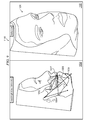
- FIGS. 1A , 1 B and 2 A- 2 D depict an example user interface screen 400 of a computer-aided surgical planning tool, in accordance with embodiments of the present disclosure.
- user interface screen 400 may be displayed to a user to assist a user to “clean” an image of the anatomy of a patient.
- a user may desire to remove image artifacts caused by noise in an imaging device.
- a user may desire to crop certain anatomical structures (e.g., orthodontic braces, teeth, etc.) such that the resulting image depicts desired anatomical structures.
- anatomical structures e.g., orthodontic braces, teeth, etc.
- user interface screen 400 of FIGS. 1A and 1B includes two different views of a segmented surface image 402 of a patient mandible 404 .
- Segmented surface image 402 may depict the outer surface of a particular portion of a patient's anatomy and may be generated in any suitable manner.
- the computer-aided surgical planning tool may generate segmented surface image 402 based on data produced by imaging the patient using radiography or other medical imaging.
- the computer-aided surgical tool may also allow a user to manipulate segmented surface image 402 to obtain different views of segmented surface image 402 .
- a user may, via one or more user interface devices (e.g., mouse, keyboard, etc.), input actions or commands to display a different view of segmented surface image 402 (e.g., rotate from the view in FIG. 1A to the view in FIG. 1B ) allowing a user various perspectives of the three-dimensional segmented surface image 402 .
- the computer-aided surgical tool may also allow a user to perform other actions upon segmented surface image 402 , including selecting and removing undesired portions of segmented surface image 402 .
- segmented surface image 402 includes not only a patient mandible 404 and lower teeth of such mandible 404 , but also the patient's upper teeth, which a user may desire to crop from image 402 .
- the curved nature of the patient mandible may render selection and deletion of undesired features difficult. For example, if a user selects the upper row of teeth of an anterior view of mandible 404 as indicated by selection 406 in FIG. 1A , selection 406 may overlap other features of mandible 404 that the user desires to retain in image 402 . Thus, deletion of such selection 406 may undesirably delete such features.
- selection 408 may overlap features on the left side of mandible 404 that the user desires to retain in image 402 , and deletion of such selection 408 may undesirably delete such features.
- the computer-aided surgical planning tool may allow a user to input an action or command (e.g., by using a mouse or other pointing device to check the check box labeled “Stretched Mode” in interface screen 400 ) to transform the representation of mandible 404 in image 402 such that the curved mandible is warped to a linear shape, as depicted in FIGS. 2A (inferior view of mandible 404 ) and 2 B (anterior view of mandible 404 ).
- such transformation may be made such that points representing the surface of mandible 404 are translated only in a latitudinal direction (e.g., remain at the same height).
- FIG. 2D depicts an anterior view of mandible 404 after the linearization of mandible 404 and selection and deletion of the upper row of teeth as shown in FIGS. 2A-2C .
- FIGS. 1A , 1 B, and 2 A- 2 D depict linearization of an image of a human mandible, similar techniques may be used for linearization of any other three-dimensional image having a curved feature (e.g., a maxilla).
- a curved feature e.g., a maxilla
- FIG. 3 is a flow chart depicting an example method 600 for transformation of a three-dimensional image with a curved profile to a three-dimensional linear profile, in accordance with embodiments of the present disclosure.
- the steps of FIG. 3 may be employed to transform an image of a mandible or maxilla from its natural curved shape to a linear shape.
- Method 600 may be performed by a computer-aided surgical planning tool, or any other suitable executable program of instructions embodied on a computer-readable medium.
- computer-aided surgical planning tool and/or a user thereof may define a base curve 414 and xy-coordinate plane for the three-dimensional image to be transformed.
- the computer-aided surgical planning tool may display a pane 412 permitting a user to interactively define base curve 414 as a semi-ellipse having a desired minor radius and major radius.
- the computer-aided surgical planning tool may overlay a view of the three-dimensional image (e.g., maxilla, mandible) perpendicular to the curved profile of the subject image to be transformed in pane 412 , which may provide the user a guide for defining dimensions of base curve 414 .
- base curve 414 may define an xy-coordinate plane (e.g., wherein the base of the semi-ellipse of base curve 414 may comprise the x-axis) and the alignment of the view of the three-dimensional image relative to the base curve may define the locations of points of the image in such xy-coordinate system.
- computer-aided surgical planning tool may map an ellipse having its minor radius a and major radius b equal to that of the semi-ellipse of the base curve 414 to a base circle having its origin at the center of the origin or the xy-plane.
- the base circle may have a radius equal to the minor radius of the ellipse, the major radius of the ellipse, or some other radius.
- An example of such mapping is illustrated in FIG. 4 , with the base circle having a radius equal to b, the major radius of the ellipse.
- computer-aided surgical planning tool may perform a first transformation transforming the subject image to an intermediate image based on the mapping of the ellipse defined by base curve 414 to the base circle.
- the image to be transformed may be a segmented surface image, which is defined by a plurality of points in three-dimensional space (e.g., x, y, and z coordinates) which serve as end points of a plurality of triangles that form the segmented surface.
- the z-axis of such coordinate system is substantially perpendicular to a view of the curved profile of the image (e.g., perpendicular to the superior or inferior view of a maxilla or mandible)
- the z-coordinate of each point P i of the segmented surface image may remain the same value during this first transformation.
- the y-coordinate of each point P i may also stay the same as the ellipse defined by the base curve may be “stretched” to the base circle in the x-axis only.
- FIG. 5 illustrates this first transformation in the xy-plane.
- computer-aided surgical planning tool may perform a second transformation transforming the intermediate image to a transformed image with the curved profile of the subject image transformed into a linear profile.
- each point of interest in the intermediate image e.g., each point of a segmented surface image
- P x ′′ b ⁇ arctan( P x ′/P y ′)
- P y ′′ ⁇ ( P x ′ 2 +P y ′ 2 )
- P z ′′ P z ′
- P x ′′, P y ′′, and P z ′′ are respectively the x, y, and z coordinates of each point P i ′ in the transformed image
- P x ′, P y ′, and P z ′ are respectively the x, y, and z coordinates of each corresponding point P i ′ in the intermediate image
- b is the radius of the circle and the major radius of base curve 114
- the computer-aided surgical planning tool may display the transformed image (e.g., to a display as shown in FIG. 2A or 2 B). After completion of step 610 , method 600 may end.
- FIG. 3 discloses a particular number of steps to be taken with respect to method 600 , it is understood that method 600 may be executed with greater or lesser steps than those depicted in FIG. 3 .
- FIG. 3 discloses a certain order of steps to be taken with respect to method 600 , the steps comprising method 600 may be completed in any suitable order.
- Method 600 may be implemented using system operable to implement method 600 , including without limitation, computer system 1200 depicted in FIG. 12 .
- method 600 may be implemented partially or fully in software embodied in computer-readable media.
- a user of the computer-aided surgical planning tool may, via a user interface, “clean” undesired artifacts from an image (e.g., by selecting undesired artifacts and deleting such selections). Following such cleaning, a user may desire to transform the transformed image back into an image with a curved profile. Accordingly, the computer-aided surgical planning tool may transform the image back into a cleaned imaged with a curved profile by applying the inverse calculations of those applied above to various points of interest in the transformed image.
- FIG. 7 depicts an example user interface screen 1000 of a computer-aided surgical planning tool, in accordance with embodiments of the present disclosure.
- User interface screen 1000 may facilitate a user's planning of an osteotomy procedure, simulating soft tissue response of a patient to movements of bony tissue below the soft tissue.
- user interface screen 1000 may include one or more panes 1002 depicting a two-dimensional view of a patient's cranio-facial features, including bony tissue and soft tissue. Images depicted in such views may be created by the computer-aided surgical planning tool or other program of instructions based on a radiograph or other image of the tissues of an individual's head.
- the computer-aided surgical planning tool may depict soft tissues of the cranio-facial features as partially transparent in panes 1002 , allowing bony tissue to be seen under the overlaying soft tissues.
- computer-aided surgical planning tool may allow a user to vary the opacity or transparency of the soft tissues.
- the computer-aided surgical planning tool may load a photograph or other image depicting superficial features of the patient's face, and overlay and contour such image over the various views depicted in panes 1002 , allowing surgical simulation of the response of superficial facial features to movement of bony tissue in an osteotomy.
- a three-dimensional camera may be used to capture an image of a patient's facial surface, and such three-dimensional facial surface image may be superimposed upon the image of the soft tissues, according to known techniques.
- one or more two-dimensional facial images may be used to capture images of a patient's facial surfaces, and such two-dimensional images may be wrapped onto the surface of the three-dimensional image of the patient's soft tissue, as illustrated in FIG. 8 .
- FIG. 8 depicts a three-dimensional image of a patient's soft tissue 1052 and a two-dimensional image of a patient's superficial facial features 1054 , including particular landmarks 1056 , 1058 , 1060 , 1062 , 1064 , and 1066 of the patient's face on each image 1052 and 1054 .
- a computer-aided surgical planning tool may present to a user a user interface similar to that depicted in FIG. 8 , and a user may, via the user interface, identify corresponding features in each of the soft tissue image 1052 and superficial facial feature image 1054 .
- the user may identify, without limitation, midline 1056 , nasion line 1058 , nostril top line 1060 , subnasale line 1062 , stomion line 1064 , and edge of eye lines 1066 .
- Similar landmark identifications can be made to other two-dimensional images of a patient's superficial features, and such two-dimensional images may be superimposed over the three-dimensional soft tissue volume image according to known techniques.
- the computer-aided surgical planning tool may allow a user to define various cuts of a patient's maxilla and mandible, thus defining portions of bony tissue that may be moved during an osteotomy (e.g., mandibular ramuses 1004 , mandible body 1006 , chin 1008 , maxilla sides 1010 , and maxilla front 1012 ), and allowing the user (e.g., via commands or actions input via keyboard, mouse, or other device) to simulate such movements using the computer-aided surgical planning tool by translating and/or rotating such various portions of bony tissue.
- an osteotomy e.g., mandibular ramuses 1004 , mandible body 1006 , chin 1008 , maxilla sides 1010 , and maxilla front 1012
- the user e.g., via commands or actions input via keyboard, mouse, or other device
- FIG. 9 depicts another example user interface screen 1100 of a computer-aided surgical planning tool that may be used in connection with osteotomy planning, in accordance with embodiments of the present disclosure.
- user interface screen 1100 may include one or more panes 1002 depicting a two-dimensional view of a patient's cranio-facial features, including bony tissue and soft tissue, and a pane 1102 having a user-rotatable three-dimensional image 1104 depicting a patient's soft tissues and/or superficial facial features.
- image 1104 may be created based on a radiograph or other medical image of a patient's external soft tissue and a photograph or other image of the patient's superficial facial features overlaid and contoured to the external soft tissue.
- a user may interact with user interface screen 1100 (e.g., using a keyboard, mouse, and/or other user input device) to simulate movement (e.g., translation or rotation) of a portion of a patient's bony tissue, and in response, the computer-aided surgical planning tool may redraw one or more of the two-dimensional images in panes 1002 to show the movement of such portion of bony tissue and simulate response of patient soft tissue to the movement, as well as redraw image 1104 to simulate response of patient soft tissue and superficial facial features to the movement.
- movement e.g., translation or rotation
- the computer-aided surgical planning tool may redraw one or more of the two-dimensional images in panes 1002 to show the movement of such portion of bony tissue and simulate response of patient soft tissue to the movement, as well as redraw image 1104 to simulate response of patient soft tissue and superficial facial features to the movement.
- user interface screen 1100 e.g., using a keyboard, mouse, and/or other user input device
- user interface 1100 may advantageously allow a user the ability to simulate movements in fixed, two-dimensional views, while viewing the patient response in a rotatable three-dimensional image.
- the computer-aided surgical planning tool may redraw based on simulated movement of bony tissue using any suitable approach.
- FIGS. 10 and 11 illustrate such an approach.
- FIGS. 10 and 11 depict a two-dimensional frontal view image 1070 and a two-dimensional right-side view image 1080 (as may be displayed in panes 1002 ) of a patient with various polygons 1090 and control points 1095 overlaid upon the images for use in modifying the images in response to simulated movement of bony tissue.
- FIGS. 10 and 11 depict a two-dimensional frontal view image 1070 and a two-dimensional right-side view image 1080 (as may be displayed in panes 1002 ) of a patient with various polygons 1090 and control points 1095 overlaid upon the images for use in modifying the images in response to simulated movement of bony tissue.
- a series of polygons 1090 (e.g., triangles) may be defined (e.g., either by a user of the computer-aided surgical planning tool or by algorithms of the computer-aided surgical planning tool recognizing features of a patient's face), each polygon 1090 defining a region of the patient's face in the particular view.
- the vertices of such polygons 1090 may serve as control points 1095 .
- the polygons and vertices may not actually appear to a user during surgical simulation, but rather may exist as a logical construct to be used by the computer-aided surgical planning tool to mathematically and/or algorithmically modify patient images.
- each control point 1095 may be translated based on its proximity to the portion of underlying bony tissue being moved and the degree to which the underlying bony tissue was moved. For example, for a simulated movement of a chin bone, control points 1095 proximate to the patient's chin may be translated by a greater distance than control points 1095 proximate to the patient's lips.
- the various pixels of the two-dimensional images and three-dimensional images of may be translated, redrawn, and displayed user interface screen 1100 based on such pixel's proximity to translated control points 1095 and the degree to which the control points 1095 were translated.
- FIG. 12 depicts a block diagram of an example computing system 1200 , in accordance with embodiments of the present disclosure.
- Computing system 1200 may be used in whole or part to provide or perform various functions and operations described above with respect to FIGS. 1-8 .
- computing system 1200 may include processor 1202 , memory 1204 , and logic 1206 .
- Computing system 1200 may comprise any suitable combination of hardware and/or software implemented in one or more modules to provide or perform the functions and operations described above with respect to FIGS. 1-11 .
- computing system 1200 may comprise a mainframe computer, general-purpose personal computer (PC), a Macintosh, a workstation, a Unix-based computer, a server computer, or any suitable processing device.
- the functions and operations described above may be performed by a pool of multiple computing systems 1200 .
- Memory 1200 may comprise any suitable arrangement of random access memory (RAM), read only memory (ROM), magnetic computer disk, CD-ROM, or other magnetic, optical or solid state storage media, or any other volatile or non-volatile memory devices that store one or more files, lists, tables, or other arrangements of information.
- FIG. 12 illustrates memory 1204 as internal to computing system, it should be understood that memory 1204 may be internal or external to computing system 1200 , depending on particular implementations. Memory 1204 may be separate from or integral to other memory devices to achieve any suitable arrangement of memory devices for use in providing or performing desired operations or functionality.
- Memory 1204 may be further operable to store logic 1206 .
- Logic 1206 generally comprises rules, algorithms, code, tables, and/or other suitable instructions executable by processor 1202 to provide or perform the functions and operations described above with respect to FIGS. 1-11 .
- Memory 1204 may be communicatively coupled to processor 1202 .
- Processor 1202 may be generally operable to execute logic to perform operations described herein.
- Processor 1202 may comprise any suitable combination of hardware and software implemented in one or more modules to provide the described function or operation.
Abstract
In accordance with embodiments of the present disclosure, a method may include mapping an ellipse with its center at the origin of an xy-coordinate plane to a circle with its center at the origin of the xy-coordinate plane. The method may also include transforming a three-dimensional subject image including a curved profile in the xy-coordinate plane to an intermediate image based at least on the mapping of the ellipse to a base circle. The method may further include transforming the intermediate image to a transformed image having a linear profile by distorting each of one or more points of interest of the intermediate image based at least on a dimension of the circle and a coordinate of such point.
Description
The present disclosure relates in general to dentofacial imaging, and more particularly to systems and methods for surgical planning using dentofacial imaging.
Dentofacial surgery, also referred to as oral and maxillofacial surgery, is often employed to correct a wide spectrum of diseases, injuries and defects in the head, neck, face, jaws and the hard and soft tissues of the oral and maxillofacial region of humans or other non-human patients. As capabilities of computers and software improve, practitioners of dentofacial surgery increasingly use computer-aided dentofacial imaging tools in order to model dentofacial features of patients, diagnose diseases, injuries, and defects, plan dentofacial surgical procedures and other treatments, and educate patients regarding diagnoses and treatments.
For example, to plan and simulate a dentofacial surgery, a practitioner may, with the aid of a computer-aided tool, virtually modify various bones or bone segments of the patient via a user interface of a computer. Such computer-aided planning and simulation may allow a practitioner to simulate effect of various surgical adjustments on a patient, including effects on a patient's aesthetic appearance. However, traditional computer-aided surgical planning and simulation tools have significant disadvantages. For example, digital images of a patient's facial tissues generated by imaging devices may include undesirable noise and other artifacts. Thus, many traditional planning and simulation tools allow a practitioner to perform “cleaning” of a digital image to remove noise from the image. However, such cleaning of noise is complicated due to the non-linear and three-dimensional shapes of the tissues comprising a human head. As another example, traditional planning and simulation tools typically allow a practitioner to make two-dimensional surgical adjustments of bone and generate a simulated two-dimensional soft-tissue response based on such adjustments, which does not allow the practitioner to view a three-dimensional model of the soft-tissue response.
In accordance with the teachings of the present disclosure, disadvantages and problems associated with traditional approaches to surgical planning using dentofacial imaging may be substantially reduced or eliminated.
In accordance with embodiments of the present disclosure, a method may include displaying one or more interactive two-dimensional images, each two-dimensional image representing at least bony tissue cranio-facial features of a patient and each two-dimensional image having one or more portions each associated with a corresponding portion of the patient's bony tissue such that a user may, via a user input device, cause movement of at least one of the one or more portions of such two-dimensional image to simulate movement of the corresponding portion of the patient's bony tissue in an osteotomy procedure. The method may also include displaying a three-dimensional image representing exterior soft-tissue cranio-facial features of the patient. The method may additionally include receiving input from a user regarding movement of a particular portion of the one or more portions of the two-dimensional image. The method may further include redrawing the three-dimensional image based at least on the movement of the particular portion of the two-dimensional image to simulate response of the exterior soft-tissue cranio-facial features of the patient to movement of a portion of the patient's bony tissue corresponding to the particular portion of the two-dimensional image.
In accordance with additional embodiments of the present disclosure, an article of manufacture may include a non-transitory computer-readable medium and computer-executable instructions carried on the computer-readable medium, the instructions executable by one or more processors and configured to cause the one or more processors to: (i) display one or more interactive two-dimensional images, each two-dimensional image representing at least bony tissue cranio-facial features of a patient and each two-dimensional image having one or more portions each associated with a corresponding portion of the patient's bony tissue such that a user may, via a user input device, cause movement of at least one of the one or more portions of such two-dimensional image to simulate movement of the corresponding portion of the patient's bony tissue in an osteotomy procedure; (ii) display a three-dimensional image representing exterior soft-tissue cranio-facial features of the patient; (iii) receive input from a user regarding movement of a particular portion of the one or more portions of the two-dimensional image; and (iv) redraw the three-dimensional image based at least on the movement of the particular portion of the two-dimensional image to simulate response of the exterior soft-tissue cranio-facial features of the patient to movement of a portion of the patient's bony tissue corresponding to the particular portion of the two-dimensional image.
In accordance with further embodiments of the present disclosure, a computing system may include a processor and a memory communicatively coupled to the processor and having stored thereon a program of instructions configured to, when executed by the processor: (i) display one or more interactive two-dimensional images, each two-dimensional image representing at least bony tissue cranio-facial features of a patient and each two-dimensional image having one or more portions each associated with a corresponding portion of the patient's bony tissue such that a user may, via a user input device, cause movement of at least one of the one or more portions of such two-dimensional image to simulate movement of the corresponding portion of the patient's bony tissue in an osteotomy procedure; (ii) display a three-dimensional image representing exterior soft-tissue cranio-facial features of the patient; (iii) receive input from a user regarding movement of a particular portion of the one or more portions of the two-dimensional image; and (iv) redraw the three-dimensional image based at least on the movement of the particular portion of the two-dimensional image to simulate response of the exterior soft-tissue cranio-facial features of the patient to movement of a portion of the patient's bony tissue corresponding to the particular portion of the two-dimensional image.
In accordance with additional embodiments of the present disclosure, a method may include mapping an ellipse with its center at the origin of an xy-coordinate plane to a circle with its center at the origin of the xy-coordinate plane. The method may also include transforming a three-dimensional subject image including a curved profile in the xy-coordinate plane to an intermediate image based at least on the mapping of the ellipse to a base circle. The method may further include transforming the intermediate image to a transformed image having a linear profile by distorting each of one or more points of interest of the intermediate image based at least on a dimension of the circle and a coordinate of such point.
In accordance with further embodiments of the present disclosure, an article of manufacture may include a non-transitory computer-readable medium and computer-executable instructions carried on the computer-readable medium, the instructions executable by one or more processors and configured to cause the one or more processors to: (i) map an ellipse with its center at the origin of an xy-coordinate plane to a circle with its center at the origin of the xy-coordinate plane; (ii) transform a three-dimensional subject image including a curved profile in the xy-coordinate plane to an intermediate image based at least on the mapping of the ellipse to a base circle; and (iii) transform the intermediate image to a transformed image having a linear profile by distorting each of one or more points of interest of the intermediate image based at least on a dimension of the circle and a coordinate of such point.
In accordance with another embodiment of the present disclosure, a computing system may include a processor and a memory communicatively coupled to the processor and having stored thereon a program of instructions configured to, when executed by the processor: (i) map an ellipse with its center at the origin of an xy-coordinate plane to a circle with its center at the origin of the xy-coordinate plane; (ii) transform a three-dimensional subject image including a curved profile in the xy-coordinate plane to an intermediate image based at least on the mapping of the ellipse to a base circle; and (iii) transform the intermediate image to a transformed image having a linear profile by distorting each of one or more points of interest of the intermediate image based at least on a dimension of the circle and a coordinate of such point.
Other technical advantages will be apparent to those of ordinary skill in the art in view of the following specification, claims, and drawings.
A more complete understanding of the present embodiments and advantages thereof may be acquired by referring to the following description taken in conjunction with the accompanying drawings, in which like reference numbers indicate like features, and wherein:
To illustrate, user interface screen 400 of FIGS. 1A and 1B includes two different views of a segmented surface image 402 of a patient mandible 404. Segmented surface image 402 may depict the outer surface of a particular portion of a patient's anatomy and may be generated in any suitable manner. For example, in some embodiments, the computer-aided surgical planning tool may generate segmented surface image 402 based on data produced by imaging the patient using radiography or other medical imaging. The computer-aided surgical tool may also allow a user to manipulate segmented surface image 402 to obtain different views of segmented surface image 402. As an example, a user may, via one or more user interface devices (e.g., mouse, keyboard, etc.), input actions or commands to display a different view of segmented surface image 402 (e.g., rotate from the view in FIG. 1A to the view in FIG. 1B ) allowing a user various perspectives of the three-dimensional segmented surface image 402. The computer-aided surgical tool may also allow a user to perform other actions upon segmented surface image 402, including selecting and removing undesired portions of segmented surface image 402.
To illustrate, in FIGS. 1A and 1B , segmented surface image 402 includes not only a patient mandible 404 and lower teeth of such mandible 404, but also the patient's upper teeth, which a user may desire to crop from image 402. However, the curved nature of the patient mandible may render selection and deletion of undesired features difficult. For example, if a user selects the upper row of teeth of an anterior view of mandible 404 as indicated by selection 406 in FIG. 1A , selection 406 may overlap other features of mandible 404 that the user desires to retain in image 402. Thus, deletion of such selection 406 may undesirably delete such features. As another example, if the user selects the upper row of teeth of a right-side lateral view of mandible 404 as indicated by selection 408 in FIG. 1B , selection 408 may overlap features on the left side of mandible 404 that the user desires to retain in image 402, and deletion of such selection 408 may undesirably delete such features.
To reduce or eliminate such disadvantages, the computer-aided surgical planning tool may allow a user to input an action or command (e.g., by using a mouse or other pointing device to check the check box labeled “Stretched Mode” in interface screen 400) to transform the representation of mandible 404 in image 402 such that the curved mandible is warped to a linear shape, as depicted in FIGS. 2A (inferior view of mandible 404) and 2B (anterior view of mandible 404). In some embodiments, such transformation may be made such that points representing the surface of mandible 404 are translated only in a latitudinal direction (e.g., remain at the same height). With such representation, a user may select the upper row of teeth, as indicated by selection 410, and delete such selection 410, as shown in FIG. 2C . Accordingly, the features that the user desires to retain are less likely to be deleted, as the linear representation of mandible 404 may reduce or avoid the deletion of other features behind the teeth to be removed from image 402. FIG. 2D depicts an anterior view of mandible 404 after the linearization of mandible 404 and selection and deletion of the upper row of teeth as shown in FIGS. 2A-2C .
Although FIGS. 1A , 1B, and 2A-2D depict linearization of an image of a human mandible, similar techniques may be used for linearization of any other three-dimensional image having a curved feature (e.g., a maxilla).
At step 602, computer-aided surgical planning tool and/or a user thereof may define a base curve 414 and xy-coordinate plane for the three-dimensional image to be transformed. For example, as depicted in FIGS. 2A-2C , the computer-aided surgical planning tool may display a pane 412 permitting a user to interactively define base curve 414 as a semi-ellipse having a desired minor radius and major radius. In addition, the computer-aided surgical planning tool may overlay a view of the three-dimensional image (e.g., maxilla, mandible) perpendicular to the curved profile of the subject image to be transformed in pane 412, which may provide the user a guide for defining dimensions of base curve 414. Furthermore, base curve 414 may define an xy-coordinate plane (e.g., wherein the base of the semi-ellipse of base curve 414 may comprise the x-axis) and the alignment of the view of the three-dimensional image relative to the base curve may define the locations of points of the image in such xy-coordinate system.
At step 604, computer-aided surgical planning tool may map an ellipse having its minor radius a and major radius b equal to that of the semi-ellipse of the base curve 414 to a base circle having its origin at the center of the origin or the xy-plane. The base circle may have a radius equal to the minor radius of the ellipse, the major radius of the ellipse, or some other radius. An example of such mapping is illustrated in FIG. 4 , with the base circle having a radius equal to b, the major radius of the ellipse.
At step 606, computer-aided surgical planning tool may perform a first transformation transforming the subject image to an intermediate image based on the mapping of the ellipse defined by base curve 414 to the base circle. To illustrate, the image to be transformed may be a segmented surface image, which is defined by a plurality of points in three-dimensional space (e.g., x, y, and z coordinates) which serve as end points of a plurality of triangles that form the segmented surface. If the z-axis of such coordinate system is substantially perpendicular to a view of the curved profile of the image (e.g., perpendicular to the superior or inferior view of a maxilla or mandible), then the z-coordinate of each point Pi of the segmented surface image may remain the same value during this first transformation. In addition, the y-coordinate of each point Pi may also stay the same as the ellipse defined by the base curve may be “stretched” to the base circle in the x-axis only. Accordingly, only the x-coordinates of each point Pi may be modified in the first transformation, and may be modified according to the following equations (assuming the base circle has a radius equal to the major radius of the base ellipse):
P x ′=P x ×b/a
P y ′=P y
P z ′=P z
where Px, Py, and Pz are respectively the x, y, and z coordinates of each point Pi in the image to be transformed, Px′, Py′, and Pz′ are respectively the x, y, and z coordinates of each corresponding point Pi′ in the intermediate image, a is the minor radius of base curve 114, and b is the radius of the circle and the major radius of base curve 114.FIG. 5 illustrates this first transformation in the xy-plane.
P x ′=P x ×b/a
P y ′=P y
P z ′=P z
where Px, Py, and Pz are respectively the x, y, and z coordinates of each point Pi in the image to be transformed, Px′, Py′, and Pz′ are respectively the x, y, and z coordinates of each corresponding point Pi′ in the intermediate image, a is the minor radius of base curve 114, and b is the radius of the circle and the major radius of base curve 114.
At step 608, computer-aided surgical planning tool may perform a second transformation transforming the intermediate image to a transformed image with the curved profile of the subject image transformed into a linear profile. In the transformation, each point of interest in the intermediate image (e.g., each point of a segmented surface image) may be modified according to the following equations:
P x ″=b×arctan(P x ′/P y′)
P y″=√(P x′2 +P y′2)
P z ″=P z′
where Px″, Py″, and Pz″ are respectively the x, y, and z coordinates of each point Pi′ in the transformed image, Px′, Py′, and Pz′ are respectively the x, y, and z coordinates of each corresponding point Pi′ in the intermediate image, and b is the radius of the circle and the major radius of base curve 114.FIG. 6 illustrates this second transformation in the xy-plane.
P x ″=b×arctan(P x ′/P y′)
P y″=√(P x′2 +P y′2)
P z ″=P z′
where Px″, Py″, and Pz″ are respectively the x, y, and z coordinates of each point Pi′ in the transformed image, Px′, Py′, and Pz′ are respectively the x, y, and z coordinates of each corresponding point Pi′ in the intermediate image, and b is the radius of the circle and the major radius of base curve 114.
At step 610, the computer-aided surgical planning tool may display the transformed image (e.g., to a display as shown in FIG. 2A or 2B). After completion of step 610, method 600 may end.
Although FIG. 3 discloses a particular number of steps to be taken with respect to method 600, it is understood that method 600 may be executed with greater or lesser steps than those depicted in FIG. 3 . In addition, although FIG. 3 discloses a certain order of steps to be taken with respect to method 600, the steps comprising method 600 may be completed in any suitable order.
Method 600 may be implemented using system operable to implement method 600, including without limitation, computer system 1200 depicted in FIG. 12 . In certain embodiments, method 600 may be implemented partially or fully in software embodied in computer-readable media.
After an image has been transformed, a user of the computer-aided surgical planning tool may, via a user interface, “clean” undesired artifacts from an image (e.g., by selecting undesired artifacts and deleting such selections). Following such cleaning, a user may desire to transform the transformed image back into an image with a curved profile. Accordingly, the computer-aided surgical planning tool may transform the image back into a cleaned imaged with a curved profile by applying the inverse calculations of those applied above to various points of interest in the transformed image.
As shown in FIG. 7 , the computer-aided surgical planning tool may depict soft tissues of the cranio-facial features as partially transparent in panes 1002, allowing bony tissue to be seen under the overlaying soft tissues. In certain embodiments, computer-aided surgical planning tool may allow a user to vary the opacity or transparency of the soft tissues. In addition, the computer-aided surgical planning tool may load a photograph or other image depicting superficial features of the patient's face, and overlay and contour such image over the various views depicted in panes 1002, allowing surgical simulation of the response of superficial facial features to movement of bony tissue in an osteotomy. For example, a three-dimensional camera may be used to capture an image of a patient's facial surface, and such three-dimensional facial surface image may be superimposed upon the image of the soft tissues, according to known techniques. As another example, one or more two-dimensional facial images may be used to capture images of a patient's facial surfaces, and such two-dimensional images may be wrapped onto the surface of the three-dimensional image of the patient's soft tissue, as illustrated in FIG. 8 . FIG. 8 depicts a three-dimensional image of a patient's soft tissue 1052 and a two-dimensional image of a patient's superficial facial features 1054, including particular landmarks 1056, 1058, 1060, 1062, 1064, and 1066 of the patient's face on each image 1052 and 1054. For example, a computer-aided surgical planning tool may present to a user a user interface similar to that depicted in FIG. 8 , and a user may, via the user interface, identify corresponding features in each of the soft tissue image 1052 and superficial facial feature image 1054. For example, the user may identify, without limitation, midline 1056, nasion line 1058, nostril top line 1060, subnasale line 1062, stomion line 1064, and edge of eye lines 1066. Similar landmark identifications can be made to other two-dimensional images of a patient's superficial features, and such two-dimensional images may be superimposed over the three-dimensional soft tissue volume image according to known techniques.
Returning to FIG. 7 , the computer-aided surgical planning tool may allow a user to define various cuts of a patient's maxilla and mandible, thus defining portions of bony tissue that may be moved during an osteotomy (e.g., mandibular ramuses 1004, mandible body 1006, chin 1008, maxilla sides 1010, and maxilla front 1012), and allowing the user (e.g., via commands or actions input via keyboard, mouse, or other device) to simulate such movements using the computer-aided surgical planning tool by translating and/or rotating such various portions of bony tissue.
A user may interact with user interface screen 1100 (e.g., using a keyboard, mouse, and/or other user input device) to simulate movement (e.g., translation or rotation) of a portion of a patient's bony tissue, and in response, the computer-aided surgical planning tool may redraw one or more of the two-dimensional images in panes 1002 to show the movement of such portion of bony tissue and simulate response of patient soft tissue to the movement, as well as redraw image 1104 to simulate response of patient soft tissue and superficial facial features to the movement. In addition, the user may interact with user interface screen 1100 (e.g., using a keyboard, mouse, and/or other user input device) to rotate image 1104 in pane 1102 to obtain varying perspectives of image 1104 to evaluate the effect of osteotomy movements on a patient's outward appearance. Thus, user interface 1100 may advantageously allow a user the ability to simulate movements in fixed, two-dimensional views, while viewing the patient response in a rotatable three-dimensional image.
The computer-aided surgical planning tool may redraw based on simulated movement of bony tissue using any suitable approach. FIGS. 10 and 11 illustrate such an approach. FIGS. 10 and 11 depict a two-dimensional frontal view image 1070 and a two-dimensional right-side view image 1080 (as may be displayed in panes 1002) of a patient with various polygons 1090 and control points 1095 overlaid upon the images for use in modifying the images in response to simulated movement of bony tissue. In some embodiments, as shown in FIGS. 10 and 11 , for each two-dimensional view of a patient (e.g., frontal view, left view, right view, etc.), a series of polygons 1090 (e.g., triangles) may be defined (e.g., either by a user of the computer-aided surgical planning tool or by algorithms of the computer-aided surgical planning tool recognizing features of a patient's face), each polygon 1090 defining a region of the patient's face in the particular view. The vertices of such polygons 1090 may serve as control points 1095. The polygons and vertices may not actually appear to a user during surgical simulation, but rather may exist as a logical construct to be used by the computer-aided surgical planning tool to mathematically and/or algorithmically modify patient images.
When a user of the computer-aided surgical planning tool simulates a movement of bony tissue, each control point 1095 may be translated based on its proximity to the portion of underlying bony tissue being moved and the degree to which the underlying bony tissue was moved. For example, for a simulated movement of a chin bone, control points 1095 proximate to the patient's chin may be translated by a greater distance than control points 1095 proximate to the patient's lips. In addition, the various pixels of the two-dimensional images and three-dimensional images of may be translated, redrawn, and displayed user interface screen 1100 based on such pixel's proximity to translated control points 1095 and the degree to which the control points 1095 were translated.
Although the present disclosure has been described in detail, it should be understood that various changes, substitutions, and alterations can be made hereto without departing from the spirit and the scope of the invention as defined by the appended claims.
Claims (18)
1. A method comprising:
mapping an ellipse with its center at the origin of an xy-coordinate plane to a circle with its center at the origin of the xy-coordinate plane;
transforming a three-dimensional subject image including a curved profile in the xy-coordinate plane to an intermediate image based at least on the mapping of the ellipse to the circle; and
transforming the intermediate image to a transformed image having a linear profile by distorting each of one or more points of interest of the intermediate image based at least on a dimension of the circle and a coordinate of such point.
2. A method according to claim 1 , wherein a radius of the circle is equal to one of a major radius of the ellipse or a minor radius of the ellipse.
3. A method according to claim 1 , wherein transforming the subject image to the intermediate image is in accordance with the following equations:
P x ′=P x ×b/a
P y ′=P y
P z ′=P z
P x ′=P x ×b/a
P y ′=P y
P z ′=P z
where Px, Py, and Pz are respectively the x, y, and z coordinates of each point Pi in the subject image, Px′, Py′, and Pz′ are respectively the x, y, and z coordinates of each corresponding point Pi′ in the intermediate image, a is a minor radius of the ellipse, and b is a major radius of the ellipse.
4. A method according to claim 1 , wherein transforming the intermediate image to the transformed image is in accordance with the following equations:
P x ″=b×arctan(P x ′/P y′)
P y″=√(P x′2 +P y′2)
P z ″=P z′
P x ″=b×arctan(P x ′/P y′)
P y″=√(P x′2 +P y′2)
P z ″=P z′
where Px″, Py″, and Pz″ are respectively the x, y, and z coordinates of each point of interest in the transformed image, Px′, Py′, and Pz′ are respectively the x, y, and z coordinates of each corresponding point of interest in the intermediate image, and b is the radius of the circle.
5. A method according to claim 1 , wherein each of the subject image and the transformed image is a segmented surface image.
6. A method according to claim 1 , in which the subject image is a graphical representation of one of a mandible and a maxilla.
7. An article of manufacture comprising:
a non-transitory computer-readable medium; and
computer-executable instructions carried on the computer-readable medium, the instructions executable by one or more processors and configured to cause the one or more processors to:
map an ellipse with its center at the origin of an xy-coordinate plane to a circle with its center at the origin of the xy-coordinate plane;
transform a three-dimensional subject image including a curved profile in the xy-coordinate plane to an intermediate image based at least on the mapping of the ellipse to the circle; and
transform the intermediate image to a transformed image having a linear profile by distorting each of one or more points of interest of the intermediate image based at least on a dimension of the circle and a coordinate of such point.
8. An article of manufacture according to claim 7 , wherein a radius of the circle is equal to one of a major radius of the ellipse or a minor radius of the ellipse.
9. An article of manufacture according to claim 7 , wherein transforming the subject image to the intermediate image is in accordance with the following equations:
P x ′=P x ×b/a
P y ′=P y
P z ′=P z
P x ′=P x ×b/a
P y ′=P y
P z ′=P z
where Px, Py, and Pz are respectively the x, y, and z coordinates of each point Pi in the subject image, Px′, Py′, and Pz′ are respectively the x, y, and z coordinates of each corresponding point Pi′ in the intermediate image, a is a minor radius of the ellipse, and b is a major radius of the ellipse.
10. An article of manufacture according to claim 7 , wherein transforming the intermediate image to the transformed image is in accordance with the following equations:
P x ″=b×arctan(P x ′/P y′)
P y″=√(P x′2 +P y′2)
P z ″=P z′
P x ″=b×arctan(P x ′/P y′)
P y″=√(P x′2 +P y′2)
P z ″=P z′
where Px″, Py″, and Pz″ are respectively the x, y, and z coordinates of each point of interest in the transformed image, Px′, Py′, and Pz′ are respectively the x, y, and z coordinates of each corresponding point of interest in the intermediate image, and b is the radius of the circle.
11. An article of manufacture according to claim 7 , wherein each of the subject image and the transformed image is a segmented surface image.
12. An article of manufacture according to claim 7 , in which the subject image is a graphical representation of one of a mandible and a maxilla.
13. A computing system, comprising:
a processor; and
a memory communicatively coupled to the processor and having stored thereon a program of instructions configured to, when executed by the processor:
map an ellipse with its center at the origin of an xy-coordinate plane to a circle with its center at the origin of the xy-coordinate plane;
transform a three-dimensional subject image including a curved profile in the xy-coordinate plane to an intermediate image based at least on the mapping of the ellipse to the circle; and
transform the intermediate image to a transformed image having a linear profile by distorting each of one or more points of interest of the intermediate image based at least on a dimension of the circle and a coordinate of such point.
14. A computing system according to claim 13 , wherein a radius of the circle is equal to one of a major radius of the ellipse or a minor radius of the ellipse.
15. A computing system according to claim 13 , wherein transforming the subject image to the intermediate image is in accordance with the following equations:
P x ′=P x ×b/a
P y ′=P y
P z ′=P z
P x ′=P x ×b/a
P y ′=P y
P z ′=P z
where Px, Py, and Pz are respectively the x, y, and z coordinates of each point Pi in the subject image, Px′, Py′, and Pz′ are respectively the x, y, and z coordinates of each corresponding point Pi′ in the intermediate image, a is a minor radius of the ellipse, and b is a major radius of the ellipse.
16. A computing system according to claim 13 , wherein transforming the intermediate image to the transformed image is in accordance with the following equations:
P x ″=b×arctan(P x ′/P y′)
P y″=√(P x′2 +P y′2)
P z ″=P z′
P x ″=b×arctan(P x ′/P y′)
P y″=√(P x′2 +P y′2)
P z ″=P z′
where Px″, Py″, and Pz″ are respectively the x, y, and z coordinates of each point of interest in the transformed image, Px′, Py′, and Pz′ are respectively the x, y, and z coordinates of each corresponding point of interest in the intermediate image, and b is the radius of the circle.
17. A computing system according to claim 13 , wherein each of the subject image and the transformed image is a segmented surface image.
18. A computing system according to claim 13 , in which the subject image is a graphical representation of one of a mandible and a maxilla.
Priority Applications (7)
| Application Number | Priority Date | Filing Date | Title |
|---|---|---|---|
| US13/081,895 US8417004B2 (en) | 2011-04-07 | 2011-04-07 | System and method for simulated linearization of curved surface |
| ES12767234.3T ES2640437T3 (en) | 2011-04-07 | 2012-04-03 | System and method for planning and three-dimensional maxillofacial surgical simulation |
| PCT/US2012/031942 WO2012138624A2 (en) | 2011-04-07 | 2012-04-03 | System and method for three-dimensional maxillofacial surgical simulation and planning |
| ES12768435T ES2718656T3 (en) | 2011-04-07 | 2012-04-03 | Simulated linearization system and method of curved surface |
| EP12768435.5A EP2693977B1 (en) | 2011-04-07 | 2012-04-03 | System and method for simulated linearization of curved surface |
| PCT/US2012/031945 WO2012138627A2 (en) | 2011-04-07 | 2012-04-03 | System and method for simulated linearization of curved surface |
| EP12767234.3A EP2693976B1 (en) | 2011-04-07 | 2012-04-03 | System and method for three-dimensional maxillofacial surgical simulation and planning |
Applications Claiming Priority (1)
| Application Number | Priority Date | Filing Date | Title |
|---|---|---|---|
| US13/081,895 US8417004B2 (en) | 2011-04-07 | 2011-04-07 | System and method for simulated linearization of curved surface |
Publications (2)
| Publication Number | Publication Date |
|---|---|
| US20120257841A1 US20120257841A1 (en) | 2012-10-11 |
| US8417004B2 true US8417004B2 (en) | 2013-04-09 |
Family
ID=46966196
Family Applications (1)
| Application Number | Title | Priority Date | Filing Date |
|---|---|---|---|
| US13/081,895 Active 2031-07-05 US8417004B2 (en) | 2011-04-07 | 2011-04-07 | System and method for simulated linearization of curved surface |
Country Status (1)
| Country | Link |
|---|---|
| US (1) | US8417004B2 (en) |
Cited By (1)
| Publication number | Priority date | Publication date | Assignee | Title |
|---|---|---|---|---|
| US20120259592A1 (en) * | 2011-04-07 | 2012-10-11 | Dolphin Imaging Systems, Llc | System and Method for Three-Dimensional Maxillofacial Surgical Simulation and Planning |
Families Citing this family (5)
| Publication number | Priority date | Publication date | Assignee | Title |
|---|---|---|---|---|
| ES2651317T3 (en) | 2011-03-01 | 2018-01-25 | Dolphin Imaging Systems, Llc | System and method to generate profile change using cephalometric monitoring data |
| US8417004B2 (en) | 2011-04-07 | 2013-04-09 | Dolphin Imaging Systems, Llc | System and method for simulated linearization of curved surface |
| FR2999071A1 (en) | 2012-12-12 | 2014-06-13 | Obl | METHOD FOR REPOSITIONING BONE FRAGMENTS FOR BONE SURGERY BASED ON THE USE OF IMPLANTS AND CUSTOM GUIDES |
| CA2918260A1 (en) * | 2013-07-17 | 2015-01-22 | Hepatiq Llc | Systems and methods for determining hepatic function from liver scans |
| MX2019002037A (en) * | 2016-08-19 | 2019-07-18 | The Methodist Hospital System | Systems and methods for computer-aided orthognathic surgical planning. |
Citations (26)
| Publication number | Priority date | Publication date | Assignee | Title |
|---|---|---|---|---|
| US5278756A (en) | 1989-01-24 | 1994-01-11 | Dolphin Imaging Systems | Method and apparatus for generating cephalometric images |
| US5342202A (en) | 1992-07-06 | 1994-08-30 | Deshayes Marie Josephe | Method for modelling cranio-facial architecture |
| US5825941A (en) | 1995-03-17 | 1998-10-20 | Mirror Software Corporation | Aesthetic imaging system |
| WO1999059106A1 (en) | 1998-05-13 | 1999-11-18 | Acuscape International, Inc. | Method and apparatus for generating 3d models from medical images |
| US20010007451A1 (en) | 1999-12-13 | 2001-07-12 | International Business Machines Corporation | Morphing processing apparatus, method, storage medium, program transmission apparatus, and animation creation apparatus |
| JP2001283191A (en) | 2000-01-25 | 2001-10-12 | Hitachi Medical Corp | Method and device for extracting and displaying specific area of organ |
| WO2001080765A1 (en) | 2000-04-25 | 2001-11-01 | Align Technology, Inc. | Systems and methods for dental treatment planning |
| WO2002003304A2 (en) | 2000-06-30 | 2002-01-10 | Tct International Plc | Predicting changes in characteristics of an object |
| US20020090123A1 (en) | 2000-12-21 | 2002-07-11 | Roland Bazin | Methods for enabling evaluation of typological characteristics of external body portion, and related devices |
| US20050018902A1 (en) | 2003-03-12 | 2005-01-27 | Cheng-Chung Liang | Image segmentation in a three-dimensional environment |
| WO2005025404A2 (en) | 2003-09-08 | 2005-03-24 | Vanderbilt University | Apparatus and methods of cortical surface registration and deformation tracking for patient-to-image alignment in relation to image-guided surgery |
| US20050244794A1 (en) | 2004-04-30 | 2005-11-03 | Kemp James H | Computer-implemented system and method for automated and highly accurate plaque analysis, reporting, and visualization |
| US7134874B2 (en) | 1997-06-20 | 2006-11-14 | Align Technology, Inc. | Computer automated development of an orthodontic treatment plan and appliance |
| US20060280351A1 (en) * | 2004-11-26 | 2006-12-14 | Bracco Imaging, S.P.A | Systems and methods for automated measurements and visualization using knowledge structure mapping ("knowledge structure mapping") |
| US7234937B2 (en) | 1999-11-30 | 2007-06-26 | Orametrix, Inc. | Unified workstation for virtual craniofacial diagnosis, treatment planning and therapeutics |
| US20070299551A1 (en) | 2006-06-09 | 2007-12-27 | Jeffrey Weinzweig | Predicting movement of soft tissue of the face in response to movement of underlying bone |
| US20080025592A1 (en) * | 2006-06-27 | 2008-01-31 | Siemens Medical Solutions Usa, Inc. | System and Method for Detection of Breast Masses and Calcifications Using the Tomosynthesis Projection and Reconstructed Images |
| US20080118143A1 (en) * | 2006-11-21 | 2008-05-22 | Mantis Vision Ltd. | 3D Geometric Modeling And Motion Capture Using Both Single And Dual Imaging |
| US20080285829A1 (en) * | 2007-05-14 | 2008-11-20 | Siemens Corporate Research, Inc. | System and Method for Consistent Detection of Mid-Sagittal Planes for Magnetic Resonance Brain Scans |
| US20090136108A1 (en) * | 2007-09-27 | 2009-05-28 | The University Of British Columbia | Method for automated delineation of contours of tissue in medical images |
| JP2009165558A (en) | 2008-01-11 | 2009-07-30 | Panasonic Corp | Method and device for measuring inside of oral cavity |
| US20110045428A1 (en) | 2009-08-21 | 2011-02-24 | Anatoliy Boltunov | Digital dental modeling |
| US20110194787A1 (en) * | 2010-02-08 | 2011-08-11 | James Jiwen Chun | Constructing Three Dimensional Images Using Panoramic Images |
| US20110285711A1 (en) * | 2010-05-21 | 2011-11-24 | Kilgard Mark J | Path rendering by covering the path based on a generated stencil buffer |
| US20120259592A1 (en) | 2011-04-07 | 2012-10-11 | Dolphin Imaging Systems, Llc | System and Method for Three-Dimensional Maxillofacial Surgical Simulation and Planning |
| US20120257841A1 (en) | 2011-04-07 | 2012-10-11 | Dolphin Imaging Systems, Llc | System and Method for Simulated Linearization of Curved Surface |
-
2011
- 2011-04-07 US US13/081,895 patent/US8417004B2/en active Active
Patent Citations (26)
| Publication number | Priority date | Publication date | Assignee | Title |
|---|---|---|---|---|
| US5278756A (en) | 1989-01-24 | 1994-01-11 | Dolphin Imaging Systems | Method and apparatus for generating cephalometric images |
| US5342202A (en) | 1992-07-06 | 1994-08-30 | Deshayes Marie Josephe | Method for modelling cranio-facial architecture |
| US5825941A (en) | 1995-03-17 | 1998-10-20 | Mirror Software Corporation | Aesthetic imaging system |
| US7134874B2 (en) | 1997-06-20 | 2006-11-14 | Align Technology, Inc. | Computer automated development of an orthodontic treatment plan and appliance |
| WO1999059106A1 (en) | 1998-05-13 | 1999-11-18 | Acuscape International, Inc. | Method and apparatus for generating 3d models from medical images |
| US7234937B2 (en) | 1999-11-30 | 2007-06-26 | Orametrix, Inc. | Unified workstation for virtual craniofacial diagnosis, treatment planning and therapeutics |
| US20010007451A1 (en) | 1999-12-13 | 2001-07-12 | International Business Machines Corporation | Morphing processing apparatus, method, storage medium, program transmission apparatus, and animation creation apparatus |
| JP2001283191A (en) | 2000-01-25 | 2001-10-12 | Hitachi Medical Corp | Method and device for extracting and displaying specific area of organ |
| WO2001080765A1 (en) | 2000-04-25 | 2001-11-01 | Align Technology, Inc. | Systems and methods for dental treatment planning |
| WO2002003304A2 (en) | 2000-06-30 | 2002-01-10 | Tct International Plc | Predicting changes in characteristics of an object |
| US20020090123A1 (en) | 2000-12-21 | 2002-07-11 | Roland Bazin | Methods for enabling evaluation of typological characteristics of external body portion, and related devices |
| US20050018902A1 (en) | 2003-03-12 | 2005-01-27 | Cheng-Chung Liang | Image segmentation in a three-dimensional environment |
| WO2005025404A2 (en) | 2003-09-08 | 2005-03-24 | Vanderbilt University | Apparatus and methods of cortical surface registration and deformation tracking for patient-to-image alignment in relation to image-guided surgery |
| US20050244794A1 (en) | 2004-04-30 | 2005-11-03 | Kemp James H | Computer-implemented system and method for automated and highly accurate plaque analysis, reporting, and visualization |
| US20060280351A1 (en) * | 2004-11-26 | 2006-12-14 | Bracco Imaging, S.P.A | Systems and methods for automated measurements and visualization using knowledge structure mapping ("knowledge structure mapping") |
| US20070299551A1 (en) | 2006-06-09 | 2007-12-27 | Jeffrey Weinzweig | Predicting movement of soft tissue of the face in response to movement of underlying bone |
| US20080025592A1 (en) * | 2006-06-27 | 2008-01-31 | Siemens Medical Solutions Usa, Inc. | System and Method for Detection of Breast Masses and Calcifications Using the Tomosynthesis Projection and Reconstructed Images |
| US20080118143A1 (en) * | 2006-11-21 | 2008-05-22 | Mantis Vision Ltd. | 3D Geometric Modeling And Motion Capture Using Both Single And Dual Imaging |
| US20080285829A1 (en) * | 2007-05-14 | 2008-11-20 | Siemens Corporate Research, Inc. | System and Method for Consistent Detection of Mid-Sagittal Planes for Magnetic Resonance Brain Scans |
| US20090136108A1 (en) * | 2007-09-27 | 2009-05-28 | The University Of British Columbia | Method for automated delineation of contours of tissue in medical images |
| JP2009165558A (en) | 2008-01-11 | 2009-07-30 | Panasonic Corp | Method and device for measuring inside of oral cavity |
| US20110045428A1 (en) | 2009-08-21 | 2011-02-24 | Anatoliy Boltunov | Digital dental modeling |
| US20110194787A1 (en) * | 2010-02-08 | 2011-08-11 | James Jiwen Chun | Constructing Three Dimensional Images Using Panoramic Images |
| US20110285711A1 (en) * | 2010-05-21 | 2011-11-24 | Kilgard Mark J | Path rendering by covering the path based on a generated stencil buffer |
| US20120259592A1 (en) | 2011-04-07 | 2012-10-11 | Dolphin Imaging Systems, Llc | System and Method for Three-Dimensional Maxillofacial Surgical Simulation and Planning |
| US20120257841A1 (en) | 2011-04-07 | 2012-10-11 | Dolphin Imaging Systems, Llc | System and Method for Simulated Linearization of Curved Surface |
Non-Patent Citations (9)
| Title |
|---|
| Hwang et al, Maxillofacial 3-dimensional image analysis for the diagnosis of facial asymmetry, Am J Orthod Dentofacial Orthop. Dec. 2006;130(6):779-85. * |
| Hwang et al.; "Maxillocfacial 3-dimensional image analysis for the diagnosis of facial asymmetry"; American Journal of Orthodontics and Dentofacial Orthopedics; 130 (6); 779-785, Jun. 28, 1905. |
| International Search Report and Written Opinion; Application No. PCT/ES2011/070133; pp. 10, Nov. 24, 2011. |
| International Search Report and Written Opinion; PCT/US2012/031942; pp. 11, Oct. 4, 2012. |
| International Search Report and Written Opinion; PCT/US2012/031945; pp. 8, Oct. 4, 2012. |
| James L. Ackerman et al., "Soft Tissue Limitations in Orthodontics: Treatment Planning Guidelines", vol. 67 No. 5 1997, p. 327-336, Jun. 19, 1905. |
| Xia et al, Computer-assistedthree dimensionasurgical plannig and simulation3D soft tissue planning and prediction, Int. J. Oral Maxillofae. Surg. 2000; 29:250. * |
| Xia et al.; "Computer-assisted three-dimensional surgical planning and simulation"; Int. J. Oral Maxillofac. Surg.; vol. 29; pp. 250-258, Jun. 22, 1905. |
| Xia et al.; "Three-dimensional Virtual Reality Surgical Planning and Simulation Workbench for Orthognathic Surgery"; Int J Adult Orthod Orthognath Surg, vol. 15, No. 4; pp. 265-282, 2000. |
Cited By (2)
| Publication number | Priority date | Publication date | Assignee | Title |
|---|---|---|---|---|
| US20120259592A1 (en) * | 2011-04-07 | 2012-10-11 | Dolphin Imaging Systems, Llc | System and Method for Three-Dimensional Maxillofacial Surgical Simulation and Planning |
| US8650005B2 (en) * | 2011-04-07 | 2014-02-11 | Dolphin Imaging Systems, Llc | System and method for three-dimensional maxillofacial surgical simulation and planning |
Also Published As
| Publication number | Publication date |
|---|---|
| US20120257841A1 (en) | 2012-10-11 |
Similar Documents
| Publication | Publication Date | Title |
|---|---|---|
| US8650005B2 (en) | System and method for three-dimensional maxillofacial surgical simulation and planning | |
| CN112087985B (en) | Simulated orthodontic treatment via real-time enhanced visualization | |
| US10143522B2 (en) | Systems and methods for planning hair transplantation | |
| US8711178B2 (en) | System and method for generating profile morphing using cephalometric tracing data | |
| Xia et al. | Three-dimensional virtual-reality surgical planning and soft-tissue prediction for orthognathic surgery | |
| US8417004B2 (en) | System and method for simulated linearization of curved surface | |
| Jiang et al. | Registration technology of augmented reality in oral medicine: A review | |
| BR112020026554A2 (en) | METHOD AND SYSTEM FOR DYNAMICALLY ADJUSTING A 3D MODEL. | |
| US20220346888A1 (en) | Device and system for multidimensional data visualization and interaction in an augmented reality virtual reality or mixed reality environment | |
| Sørensen et al. | A new virtual reality approach for planning of cardiac interventions | |
| US20230054394A1 (en) | Device and system for multidimensional data visualization and interaction in an augmented reality virtual reality or mixed reality image guided surgery | |
| EP2693977B1 (en) | System and method for simulated linearization of curved surface | |
| Qian et al. | An automatic tooth reconstruction method based on multimodal data | |
| Neubauer et al. | Advanced virtual corrective osteotomy | |
| Wang et al. | Haptics and virtual reality for oral and maxillofacial surgery | |
| Xia et al. | PC-based virtual reality surgical simulation for orthognathic surgery | |
| JP2005074136A (en) | Modeling method of face profile and program for modeling face profile | |
| CN115222887A (en) | Method for designing craniomaxillofacial skeleton operation plan based on appearance |
Legal Events
| Date | Code | Title | Description |
|---|---|---|---|
| AS | Assignment |
Owner name: DOLPHIN IMAGING SYSTEMS, LLC, CALIFORNIA Free format text: ASSIGNMENT OF ASSIGNORS INTEREST;ASSIGNOR:LIAO, SWANWA;REEL/FRAME:026091/0962 Effective date: 20110406 |
|
| STCF | Information on status: patent grant |
Free format text: PATENTED CASE |
|
| FPAY | Fee payment |
Year of fee payment: 4 |
|
| MAFP | Maintenance fee payment |
Free format text: PAYMENT OF MAINTENANCE FEE, 8TH YEAR, LARGE ENTITY (ORIGINAL EVENT CODE: M1552); ENTITY STATUS OF PATENT OWNER: LARGE ENTITY Year of fee payment: 8 |