US8325938B2 - Handsfree call apparatus, acoustic reproducing apparatus with handsfree call function, and handsfree call method - Google Patents
Handsfree call apparatus, acoustic reproducing apparatus with handsfree call function, and handsfree call method Download PDFInfo
- Publication number
- US8325938B2 US8325938B2 US12/537,474 US53747409A US8325938B2 US 8325938 B2 US8325938 B2 US 8325938B2 US 53747409 A US53747409 A US 53747409A US 8325938 B2 US8325938 B2 US 8325938B2
- Authority
- US
- United States
- Prior art keywords
- speaker
- call
- audio signal
- handsfree
- user
- Prior art date
- Legal status (The legal status is an assumption and is not a legal conclusion. Google has not performed a legal analysis and makes no representation as to the accuracy of the status listed.)
- Expired - Fee Related, expires
Links
Images


Classifications
-
- H—ELECTRICITY
- H04—ELECTRIC COMMUNICATION TECHNIQUE
- H04M—TELEPHONIC COMMUNICATION
- H04M1/00—Substation equipment, e.g. for use by subscribers
- H04M1/60—Substation equipment, e.g. for use by subscribers including speech amplifiers
- H04M1/6033—Substation equipment, e.g. for use by subscribers including speech amplifiers for providing handsfree use or a loudspeaker mode in telephone sets
- H04M1/6041—Portable telephones adapted for handsfree use
- H04M1/6075—Portable telephones adapted for handsfree use adapted for handsfree use in a vehicle
- H04M1/6083—Portable telephones adapted for handsfree use adapted for handsfree use in a vehicle by interfacing with the vehicle audio system
-
- H—ELECTRICITY
- H04—ELECTRIC COMMUNICATION TECHNIQUE
- H04M—TELEPHONIC COMMUNICATION
- H04M9/00—Arrangements for interconnection not involving centralised switching
- H04M9/08—Two-way loud-speaking telephone systems with means for conditioning the signal, e.g. for suppressing echoes for one or both directions of traffic
- H04M9/082—Two-way loud-speaking telephone systems with means for conditioning the signal, e.g. for suppressing echoes for one or both directions of traffic using echo cancellers
-
- H—ELECTRICITY
- H04—ELECTRIC COMMUNICATION TECHNIQUE
- H04M—TELEPHONIC COMMUNICATION
- H04M2250/00—Details of telephonic subscriber devices
- H04M2250/74—Details of telephonic subscriber devices with voice recognition means
Definitions
- the present invention relates to a handsfree call apparatus, acoustic reproducing apparatus with a handsfree call function, and handsfree call method, which enable a handsfree call.
- Handsfree call apparatuses have been proposed whereby a user can perform a call without holding a phone handset.
- an in-vehicle handsfree apparatus has also been proposed whereby a driver can perform a handsfree call.
- this in-vehicle handsfree apparatus for example, as shown in FIG. 1 , there has been proposed an in-vehicle handsfree apparatus wherein a microphone 102 for transmission of a calling party (driver in this case) 101 is attached to a sun visor 103 provided to the inner side of the front glass of a vehicle.
- a microphone 102 for transmission of a calling party (driver in this case) 101 is attached to a sun visor 103 provided to the inner side of the front glass of a vehicle.
- speakers employed for acoustic reproduction of played audio of the in-vehicle audio playing apparatus thereof can be employed for acoustic reproduction of receiver audio.
- Speakers 104 employed for acoustic reproduction of played sound of the in-vehicle audio playing apparatus are provided, as shown in FIG. 1 , for example, by being embedded in the doors of a driving seat, passenger seat, and backseat of the vehicle and attached thereto, respectively. Accordingly, in the case of FIG. 1 , for example, in a case where a driver performs a handsfree call, an arrangement is made wherein a microphone 102 of the sun visor 103 , and the speaker 104 attached to the door on the left side of the driving seat are employed.
- the case in FIG. 1 includes a problem of howling caused by the microphone 102 collecting the sound emitted from the speaker 104 .
- the case in FIG. 1 includes a problem wherein the disposed positions of the microphone 102 and speaker 104 are separated such as between the sun visor 103 and the door, and accordingly, there is difficulty in how to lay the wiring.
- an in-vehicle handsfree call apparatus such as shown in FIG. 2 has been proposed in Japanese Unexamined Patent Application Publication No. 2001-146136.
- a speaker 112 for a receiver is provided to one of both shoulder portions sandwiching a headrest 114 above a backrest portion 111 of a seat of a vehicle, and a microphone 113 for a transmitter is provided to the other.
- the headrest 114 and a user serve as noise insulation, and howling is reduced, and also wiring as to the speaker 112 and microphone 113 can be shared, for example, such as shown in a wiring portion 115 in FIG. 2 .
- the speaker 112 of the in-vehicle handsfree call apparatus in Japanese Unexamined Patent Application Publication No. 2001-146136 can be employed for music playing of car audio.
- the speaker 112 has to be provided only on the one side, of both shoulder portions sandwiching the headrest 114 above the backrest portion 111 , where the microphone 113 is not provided.
- a handsfree call apparatus includes: a speaker held in the vicinity of a user's ear by a holding unit with a speaker unit thereof not being attached to a baffle board so as to mix sounds emitted from the front and back of a diaphragm thereof; a microphone, which is provided to a region where sounds emitted from the front and back of the diaphragm of the speaker are mixed and canceled out, configured to collect the call voice of the user; an output unit configured to output a call voice signal of the user from the microphone to transmit this to a call partner; and an input unit configured to receive a call voice signal from the call partner to supply this to the speaker.
- the speaker is held in the vicinity of the user's ear by the holding unit with the speaker unit thereof not being attached to the baffle board so as to mix sounds emitted from the front and back of the diaphragm thereof.
- the microphone is disposed in a region where sounds emitted from the front and back of the diaphragm of the speaker are mutually mixed and canceled out. Therefore, the microphone rarely collects audio emitted from the speaker, and accordingly, howling due to the microphone collecting sound emission audio from the speaker does not occur.
- the microphone can be disposed in the vicinity of the speaker, and accordingly, laying of wiring can be readily performed. Note that an arrangement may be made wherein another speaker other than the above-mentioned speaker is disposed instead of the microphone, and the speaker thereof serves as a microphone.
- an acoustic reproducing apparatus with a handsfree call function includes: first and second speakers held in the vicinity of a user's left and right ears by a holding unit respectively with a speaker unit thereof not being attached to a baffle board so as to mix sounds emitted from the front and back of a diaphragm thereof; an audio signal generating unit configured to generate an audio signal to be supplied to the first and second speakers to be subjected to acoustic reproduction; a microphone, which is provided to a region where sounds emitted from the front and back of the diaphragm of at least one speaker of the first and second speakers are mixed and canceled out, configured to collect the call voice of the user; an output unit configured to output a call voice signal of the user from the microphone to transmit this to a call partner; a first switch circuit, which is provided between the output unit and the microphone, configured to form a route of the call voice signal of the user from the microphone to the output unit at the time of a call; an input unit
- the first and second speakers for left and right two-channels are held in the vicinity of both of the user's ears by the holding unit with a speaker unit thereof not being attached to a baffle board so as to mix sounds emitted from the front and back of a diaphragm thereof.
- the microphone is disposed in a region where sounds emitted from the front and back of the diaphragm of at least one speaker of the first and second speakers are mixed and canceled out. Therefore, the microphone rarely collects audio emitted from the one speaker, and accordingly, howling due to the microphone collecting sound emission audio from the one speaker thereof does not occur even in the event that the microphone is disposed in a position adjacent to the one speaker thereof.
- an arrangement may be made wherein the speakers of the left and right channels are disposed on the both shoulder portions above the backrest portion of a seat respectively, and the microphone is disposed in the vicinity of one speaker thereof. Accordingly, for example, even if an arrangement is made wherein a speaker for a handsfree call is employed for music playing of a car stereo, this arrangement can be taken as an arrangement wherein howling does not occur easily.
- the microphone can be disposed in the vicinity of a speaker, whereby laying of wiring can be readily performed. It goes without saying that an arrangement may be made wherein another speaker other than the above-mentioned speakers is disposed instead of the microphone, and the speaker thereof serves as a microphone.
- the handsfree call apparatus even in the event that a microphone (or speaker serving as a microphone) is disposed in the vicinity of a speaker, the microphone thereof rarely collects audio emitted from the speaker thereof, and accordingly, howling due to sound emission audio from the speaker does not occur. Moreover, the microphone can be disposed in the vicinity of the speaker, whereby laying of wiring can be readily performed.
- an arrangement is made wherein howling can be prevented even if the microphone is disposed in the vicinity of the speaker, and accordingly, the microphone and another speaker are disposed distantly, whereby howling due to collecting audio from the other speaker thereof can be prevented. Therefore, a speaker for handsfree can also be readily employed as a speaker for music playing.
- FIG. 1 is a diagram for describing an example of an in-vehicle handsfree call apparatus according to the related art
- FIG. 2 is a diagram for describing another example of an in-vehicle handsfree call apparatus according to the related art
- FIG. 3 is a block diagram of a configuration example of an embodiment (first embodiment) of a handsfree call apparatus according to the present invention
- FIG. 4 is a diagram for describing the disposed positions of a speaker and microphone for a handsfree call with the embodiment of the handsfree call apparatus according to the present invention
- FIG. 5 is a diagram employed for describing a sound pressure zero region with the embodiment of the handsfree call apparatus according to the present invention.
- FIG. 6 is a diagram illustrating an example of the disposed positions of the speaker and microphone for a handsfree call with the embodiment of the handsfree call apparatus according to the present invention
- FIG. 7 is a block diagram illustrating a configuration example of an embodiment (second embodiment) of an acoustic reproducing apparatus with a handsfree call function according to the present invention
- FIG. 8 is a diagram illustrating an example of the disposed positions of the speaker and microphone according to the second embodiment of the present invention.
- FIG. 9 is a diagram illustrating an example of an operating button group according to the second and seventh embodiments of the present invention.
- FIG. 10 is a block diagram illustrating a configuration example of an embodiment (third embodiment) of an acoustic reproducing apparatus with a handsfree call function according to the present invention.
- FIG. 11 is a block diagram illustrating a configuration example of an embodiment (fourth embodiment) of an acoustic reproducing apparatus with a handsfree call function according to the present invention
- FIG. 12 is a block diagram illustrating a configuration example of an embodiment (fifth embodiment) of an acoustic reproducing apparatus with a handsfree call function according to the present invention
- FIG. 13 is a diagram for describing a call between devices (extension call) according to the fifth embodiment of the present invention.
- FIG. 14 is a diagram illustrating an example of an operating button group according to the fifth and ninth embodiments of the present invention.
- FIG. 15 is a block diagram illustrating a configuration example of an embodiment (sixth embodiment) of an acoustic reproducing apparatus with a handsfree call function according to the present invention
- FIG. 16 is a diagram for describing a call between devices (extension call) according to the sixth embodiment of the present invention.
- FIG. 17 is a diagram illustrating an example of an operating button group according to the sixth and tenth embodiments of the present invention.
- FIG. 18 is a block diagram illustrating a configuration example of yet another embodiment of an acoustic reproducing apparatus with a handsfree call function according to the present invention.
- FIG. 19 is a diagram employed for describing principal components of the acoustic reproducing apparatus with a handsfree call function according to the embodiment in FIG. 18 ;
- FIG. 20 is a block diagram of a configuration example of a seventh embodiment of an acoustic reproducing apparatus with a handsfree call function according to the present invention.
- FIGS. 21A and 21B are diagrams for describing an example of a speaker attachment configuration with the seventh embodiment of the acoustic reproducing apparatus with a handsfree call function according to the present invention
- FIG. 22 is a diagram employed for describing the disposed position of a speaker employed for the seventh embodiment of the acoustic reproducing apparatus with a handsfree call function according to the present invention
- FIG. 23 is a diagram employed for describing a movement state by a speaker moving mechanism employed for the seventh embodiment of the acoustic reproducing apparatus with a handsfree call function according to the present invention
- FIG. 24 is a diagram employed for describing a movement state of the speaker moving mechanism employed for the seventh embodiment of the acoustic reproducing apparatus with a handsfree call function according to the present invention.
- FIG. 25 is a diagram for describing an example of the speaker movement mechanism employed for the seventh embodiment of the acoustic reproducing apparatus with a handsfree call function according to the present invention.
- FIG. 26 is a diagram for describing an example of the speaker moving mechanism employed for the seventh embodiment of the acoustic reproducing apparatus with a handsfree call function according to the present invention.
- FIG. 27 is a flowchart for describing the operations of principal components according to the seventh embodiment of the acoustic reproducing apparatus with a handsfree call function according to the present invention.
- FIG. 28 is a block diagram illustrating a configuration example of an eighth embodiment of an acoustic reproducing apparatus with a handsfree call function according to the present invention.
- FIG. 29 is a block diagram illustrating a configuration example of a ninth embodiment of an acoustic reproducing apparatus with a handsfree call function according to the present invention.
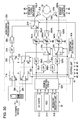
- FIG. 30 is a block diagram illustrating a configuration example of a portion of the ninth embodiment of the present invention.
- FIG. 32 is a diagram for describing a call between devices (extension call) according to the ninth embodiment of the present invention.
- FIG. 33 is a block diagram illustrating a configuration example of a tenth embodiment of an acoustic reproducing apparatus with a handsfree call function according to the present invention.
- FIG. 34 is a diagram for describing a call between devices (extension call) according to the tenth embodiment of the present invention.
- FIGS. 35A through 35C are diagrams for describing another disposed position example of a speaker and microphone for a handsfree call according to the present invention.
- FIG. 36 is a diagram illustrating a disposed position example of a speaker and microphone for a handsfree call with another embodiment of a handsfree call apparatus according to the present invention.
- a sound wave Sf emitted from the front of the diaphragm of the speaker unit, and a sound wave Sb emitted from the back thereof are mixed.
- the phase of the sound wave Sf emitted from the front of the diaphragm of the speaker unit (see (A) in FIG. 5 )
- the phase of the sound wave Sb emitted from the back of the diaphragm (see (C) in FIG. 5 ) become reversed phases mutually.
- the sound pressure zero region Zo can be confirmed by employing the microphone to collect emitted sound waves from the speaker 1 when reproducing audio at the speaker 1 .
- FIG. 4 illustrates this region with a dashed line 5 .
- a microphone 2 for collection of transmitted audio of a transmitter is disposed in an arbitrary position of the sound pressure zero region Zo.
- transmitter refers to a transmitting party of a call
- receiver refers to the receiving party of a call.
- the neighborhood of the outer circumferential frame portion of the diaphragm of the speaker 1 becomes the sound pressure zero region Zo, and accordingly, the microphone 2 is fixed to the outer circumferential frame portion of the diaphragm of the speaker 1 thereof, and the microphone 2 is disposed in the sound pressure zero region Zo. That is to say, with this example, the holding unit of the microphone 2 serves as the speaker 1 .
- the speaker 1 is fixed to the left ear side of the user 3 of a headrest portion 7 of a seat 6 where the user 3 sits, such that the vibrating face of the diaphragm 1 C faces the user side.
- the speaker 1 is attached to the headrest portion 7 in a state in which the vibrating face of the diaphragm 1 C slants around 45 degrees for example as to the long piece direction of the headrest portion 7 .
- the microphone 2 is fixed to the position corresponding to the mouth of the user 3 with the outer circumferential frame portion 1 A of the diaphragm 1 C of the speaker 1 .
- the speaker 1 is attached to the headrest portion 7 in a state in which the attachment position of the microphone 2 of the outer circumferential frame portion 1 A of the speaker 1 is at the lowermost end position.
- Call voice emitted from the user 3 is collected by the microphone 2 .
- a call voice signal obtained by being subjected to acousto-electric conversion at the microphone 2 is supplied to a low-pass filter 12 through a microphone amplifier 11 .
- the output audio signal of the low-pass filter 12 is supplied to the transmitter audio input terminal of a cellular telephone terminal 4 through an audio signal output terminal 13 .
- the receiver audio signal from a call partner from the receiver audio output terminal of the cellular telephone terminal 4 is input to the handsfree call apparatus 10 according to the present embodiment through an audio signal input terminal 14 . Subsequently, the receiver audio signal input through the audio signal input terminal 14 is supplied to the speaker 1 through a power amplifier 15 . In this case, the speaker 1 is disposed near the user's ear, and accordingly, the sound volume of call voice emitted from the speaker 1 can be suppressed. This is also more effective for howling prevention.
- the low-pass filter 12 is provided according to the following reason. Specifically, of sounds emitted from the front and back of the diaphragm 1 C of the bare speaker 1 , and particularly with regard to low frequencies, cancellation effects of the sounds emitted from the front and back of the diaphragm 1 C are great. The middle through high frequency components of the sounds emitted from the front and back of the diaphragm 1 C of the bare speaker 1 are attenuated greatly in the sound pressure zero region Zo, but do not become zero completely.
- the components of the sounds emitted from the front and back of the diaphragm 1 C of the bare speaker 1 are restricted to only call voice band components of which the sound pressure is approximately completely canceled out and becomes zero when the microphone 2 is disposed in the above-mentioned sound pressure zero region Zo.
- a cut-off frequency at the low-pass filter 12 is set to, for example, around 2 kHz.
- the cut-off frequency of the low-pass filter 12 differs depending on the use environment of the handsfree call apparatus, and for example, it can be conceived that the cut-off frequency is at or below 1 kHz.
- a call can be performed stably without concern about howling.
- the microphone 2 may be fixed to the speaker 1 , and in this case, the speaker 1 and microphone 2 approximate, and may be handled as one unit, thereby providing an advantage wherein attachment, wiring, or the like can be readily facilitated.
- the speaker 1 and microphone 2 have been disposed only on the left side of the user, but it goes without saying that the speaker 1 and microphone 2 may be disposed on the right side of the user.
- speakers and microphones are disposed on both of the left and right sides of the user as with the same layout relationship of the above-mentioned speaker 1 and microphone 2 , and both may be employed for a handsfree call.
- sounds are collected at the left and right microphones, transmitter audio signals passed through the low-pass filter are combined, and are transmitted from the audio signal output terminal 13 .
- the receiver audio signal from a call partner is distributed to the left and right speakers, and the distributed signals are subjected to acoustic reproduction.
- FIG. 7 is a block diagram illustrating a configuration example of an embodiment (second embodiment) of an acoustic reproducing apparatus with a handsfree call function.
- the same components as those of the above-described handsfree call apparatus 10 are denoted with the same reference numerals.
- the present second embodiment is a case where, with a stereo acoustic reproducing apparatus of left and right two channels, the speaker of one channel thereof is employed as a speaker for a handsfree call function.
- the acoustic reproducing apparatus with a handsfree call function is configured of an audio signal processing unit 20 , music source unit 30 serving as an example of audio signal generating unit, control unit 40 , operating button group 41 , and cellular telephone terminal 4 .
- a speaker 1 L for the left channel and a speaker 1 R for the right channel are attached to both sides of a headrest portion 52 of a seat 51 where the user 3 sits.
- These speakers 1 L and 1 R for left and right channels have a bare speaker configuration.
- the microphone 2 for collecting transmitter audio of the transmitter is disposed in an arbitrary position of the sound pressure zero region Zo.
- the neighborhood of the outer circumferential frame portion of the diaphragm of the speaker 1 L becomes the sound pressure zero region Zo, and accordingly, with the present embodiment as well, the microphone 2 is fixed to the outer circumferential frame portion of the diaphragm of the speaker 1 L thereof, and is disposed in the sound pressure zero region Zo.
- the speaker 1 L for the left channel is employed for a handsfree call function, and accordingly, the microphone 2 is provided to only the speaker 1 L for the left channel, and the speaker for the right channel is not employed for a handsfree call.
- the audio signals for the left and right two channels from the CD player 31 C, HDD 31 H, and broadcast reception unit 31 B are supplied to the audio signal processing unit 20 .
- the audio signals for the two channels from the CD player 31 C, HDD 31 H, and broadcast reception unit 31 B are input to a source selecting circuit 32 .
- the operating button group 41 includes, as shown in FIG. 9 , selection buttons such as a phone button 61 , CD button 62 , HDD button 63 , broadcast button 64 , and so forth, and volume control knob 65 .
- selection buttons such as a phone button 61 , CD button 62 , HDD button 63 , broadcast button 64 , and so forth, and volume control knob 65 .
- the operating signal corresponding to button operations by the user at the operating button group 41 is supplied to the control unit 40 .
- the operating button group 41 also includes, in addition to the selection buttons such as described above, repeat play, and shuffle play as to the CD player 31 C and HDD 31 H, and an operating button for broadcast channel selection with the broadcast reception unit 31 B, and so forth.
- the selection buttons such as described above, repeat play, and shuffle play as to the CD player 31 C and HDD 31 H
- an operating button for broadcast channel selection with the broadcast reception unit 31 B and so forth.
- illustrations and descriptions regarding these buttons will be omitted.
- the control unit 40 supplies a source selection signal to the source selecting circuit 32 .
- the source selecting circuit 32 is selectively controlled by the source selection signal thereof, and performs selection control so as to select the music source corresponding to the pressed selection button. For example, upon the CD button 62 being pressed, the source selecting circuit 32 selectively outputs the audio signals of the left and right two channels from the CD player 31 C. Similarly, the source selecting circuit 32 selectively outputs the audio signals of the left and right two channels from the HDD 31 H upon the HDD button 63 being pressed, and outputs the audio signals of the left and right two channels from the broadcast reception unit 31 B upon the broadcast button 64 being pressed.
- the audio signal of the left channel is supplied to a mixing circuit 36 with a receiver audio signal at the time of a call through an attenuating unit 33 L.
- the output audio signal of the mixing circuit 36 is supplied to the speaker 1 L for the left channel through a potentiometer 34 L for volume control and a power amplifier 35 L, and is reproduced acoustically.
- the audio signal of the right channel of the audio signals of the two channels from the source selecting circuit 32 is supplied to the speaker 1 R for the right channel through an attenuating unit 33 R, potentiometer 34 R for volume control, and power amplifier 35 R, and is reproduced acoustically.
- the speakers 1 L and 1 R are disposed in the vicinity of the user's ears, and accordingly, sounds emitted from the speakers 1 L and 1 R can be suppressed to a small output volume.
- the attenuating units 33 L and 33 R are for reducing the sound volume of a music source from the music source unit 30 when performing a handsfree call.
- the attenuation amounts of the attenuating units 33 L and 33 R are zero. That is to say, in the music source playing mode, the attenuating units 33 L and 33 R inputs/outputs an input audio signal without attenuation.
- the control unit 40 Upon the user pressing the phone button 61 of the operating button group 41 , the control unit 40 detects this to switch the music source playing mode to the handsfree call mode, supplies an attenuation control signal to the attenuating units 33 L and 33 R so as to attenuate the audio signal from the source selecting circuit 32 .
- the attenuation amounts of the attenuating units 33 L and 33 R are selected so as to attenuate the audio signal of a music source to the extent of a call not being hindered.
- the attenuation amounts of the attenuating units 33 L and 33 R may the same.
- the attenuation amount of the attenuating unit 33 L for the left channel is set to be greater than the attenuation amount of the attenuating unit 33 R for the right channel.
- the attenuation amount of the attenuating unit 33 L for the left channel is set to ⁇ 20 dB
- the attenuation amount of the attenuating unit 33 R for the right channel is set to ⁇ 10 dB, at the time of a handsfree call.
- the potentiometers 34 L and 34 R for volume control are for controlling the volumes of the audio signals supplied to the speakers 1 L and 1 R at the time of the volume control knob 65 being operated by the user, in accordance with the operation thereof.
- the control unit 40 detects this to control the potentiometers 34 L and 34 R for volume control so as to increase the sound volumes of the audio signals to be supplied to the speakers 1 L and 1 R for the worth of the rotational amount thereof. Also, upon the user rotating the volume control knob 65 to the left for example, the control unit 40 detects this to control the potentiometers 34 L and 34 R for volume control so as to decrease the sound volumes of the audio signals to be supplied to the speakers 1 L and 1 R for the worth of the rotational amount thereof.
- call voice emitted from the user 3 is collected, subjected to acousto-electric conversion to generate a call voice signal, and the call voice signal is input to the audio signal processing unit 20 .
- the call voice signal from the microphone 2 is supplied to a low-pass filter 22 similar to the above-mentioned low-pass filter 12 through a microphone amplifier 21 .
- the output audio signal of the low-pass filter 22 is supplied to a call side terminal (input terminal) T of a switch circuit 23 to be switched between at the time of a call and at the time of music source playing.
- a music playing side terminal (input terminal) M of the switch circuit 23 is grounded.
- a switching terminal (output terminal) of the switch circuit 23 is connected to the transmitter audio input terminal of the cellular telephone terminal 4 through an audio signal output terminal 24 with the present embodiment. That is to say, the transmitter audio signal of the user 3 collected at the microphone 2 is supplied to the transmitter audio input terminal of the cellular telephone terminal 4 .
- a music playing side terminal (input terminal) M of the switch circuit 26 is grounded with the present embodiment.
- a switching terminal (output terminal) of the switch circuit 26 is connected to the mixing circuit 36 , and at the time of a call, a receiver audio signal from the call partner is supplied to the mixing circuit 36 through the call side terminal T. Subsequently, the output audio signal of the mixing circuit 36 is supplied to the speaker 1 L for the left channel through the potentiometer 34 L for volume control and power amplifier 35 L, and is reproduced acoustically.
- a music source from the music source unit 30 is supplied to the speakers 1 L and 1 R for the left and right channels, and is reproduced acoustically.
- the attenuation amounts at the attenuating units 33 L and 33 R at this time are zero.
- the output volume is changed by the operations of the volume control knob 65 of the operating button group 41 .
- the source of the audio signals of the two channels to be transmitted from the music source unit 30 is changed by the CD button 62 , HDD button 63 , broadcast button 64 or the like of the operating button group 41 being operated.
- the user performs incoming call response operations (e.g., offhook operations) at the cellular telephone terminal 4 , and also presses the phone button 61 of the operating button group 41 .
- incoming call response operations e.g., offhook operations
- the user 3 transmits an outgoing call from the cellular telephone terminal 4 to a call partner to perform a handsfree call
- the user 3 performs outgoing call operations to the call partner at the cellular telephone terminal 4 , and also presses the phone button 61 .
- the control unit 40 Upon the user pressing the phone button 61 of the operating button group 41 , the control unit 40 detects this to switch the audio signal processing unit 20 to the handsfree call mode. Subsequently, the control unit 40 supplies to the switch circuits 23 and 26 a switching control signal for switching these to the call side terminals T, and also outputs the above-mentioned attenuation control signal to the attenuating units 33 L and 33 R.
- the attenuating unit 33 L attenuates an input audio signal thereof by ⁇ 20 dB, and outputs this.
- the attenuating unit 33 R attenuates an input audio signal thereof by ⁇ 10 dB, and outputs this.
- a transmitter audio signal of spoken audio of the user 3 collected at the microphone 2 is supplied to the cellular telephone terminal 4 through the microphone amplifier 21 , low-pass filter 22 , switch circuit 23 , and audio signal output terminal 24 , and is transmitted to the call partner through a cellular telephone network. Also, a receiver audio signal from the call partner, received at the cellular telephone terminal 4 is input to the audio signal processing unit 20 through the audio signal input terminal 25 .
- the receiver audio signal input from the call partner is mixed with the audio signal of the left channel from the attenuating unit 33 L at the mixing circuit 36 , and is supplied to the speaker 1 L through the potentiometer 34 L for volume control and power amplifier 35 L. Therefore, the receiver audio signal is mixed with the attenuated audio signal of the left channel, and is reproduced acoustically by the speaker 1 L. Also, the audio signal of the right channel is attenuated to ⁇ 10 dB, and is reproduced acoustically by the speaker 1 R for the right channel.
- the audio signals of the two channels from the music source unit 30 are attenuated by ⁇ 20 dB and ⁇ 10 dB at the attenuating units 33 L and 33 R respectively, thereby preventing call voice from becoming inaudible.
- a handsfree call with a call partner through the cellular telephone terminal 4 can be performed.
- the speakers 1 L and 1 R are disposed in the vicinity of the user's ears, and accordingly, the original sound emission output volume (sound pressure) may be suppressed. According to a combination of this advantage and that the microphone 2 is disposed in the sound pressure zero region Zo of the speaker 1 L, with the present embodiment, a handsfree call can be performed while preventing howling, and listening to a music source.
- a handsfree call can be performed while listening to a music source such as described above.
- response to an incoming call as to the cellular telephone terminal 4 , and outgoing call operations are handled by allowing the user to perform incoming call response operations and outgoing call operations with the cellular telephone terminal 4 , respectively.
- the cellular telephone terminal 4 includes a connection terminal with a computer
- a handsfree kit which employs the connection terminal thereof to realize automatic incoming call/call-ending, and an outgoing call function to a registered partner with a single touch of a button. Therefore, this handsfree kit function is included in the control unit 40 , whereby the control unit 40 can perform functions such as automatic incoming call/call-ending, and so forth, obviously.
- the present third embodiment is a case where a microphone for a handsfree call function is employed for collecting audio control words when performing selection control and volume control of each source by audio recognition. Note that, with the present embodiment, control by the operating buttons of the operating button group 41 can also be performed, and further, control by audio recognition can be performed.
- FIG. 10 is a block diagram illustrating a configuration example of the third embodiment of the acoustic reproducing apparatus with a handsfree call function.
- the same components as those of the configuration example of the second embodiment in FIG. 7 are denoted with the same reference numerals, and description thereof will be omitted.
- the speaker 1 L for the left channel and the speaker 1 R for the right channel are attached to both sides of the headrest portion 52 of the seat 51 where the user 3 sits.
- These speakers 1 L and 1 R for left and right channels have a bare speaker configuration.
- the microphone 2 for collecting transmitter audio of the transmitter (user 3 ) is disposed in an arbitrary position of the sound pressure zero region Zo.
- the microphone 2 is fixed to the outer circumferential frame portion of the diaphragm of the speaker 1 L thereof, and the microphone 2 is disposed in the sound pressure zero region Zo.
- an audio signal from the microphone 2 through the low-pass filter 22 is supplied to a switching terminal (input terminal) of a switch circuit 23 M. Subsequently, with the present embodiment, the audio signal from the microphone 2 through the low-pass filter 22 is supplied from a call side terminal (output terminal) T of the switch circuit 23 M to the transmitter audio input terminal of the cellular telephone terminal 4 through an audio signal output terminal 24 .
- the audio signal from the microphone 2 through the low-pass filter 22 is supplied to a speech recognizing circuit 42 through a music playing side terminal (output terminal) M of the switch circuit 23 M.
- the speech recognizing circuit 42 is configured so as to recognize a spoken word for source selection, such as “CD”, “HDD”, “broadcast”, or the like, and a spoken word for control, such as “repeat”, “change”, “volume up”, “volume down”, or the like. Subsequently, audio recognition results at the speech recognizing circuit 42 are supplied to the control unit 40 .
- the control unit 40 performs control corresponding to the audio recognition results from the speech recognizing circuit 42 . For example, when determining that the audio recognition results of a spoken word for source selection, such as “CD”, “HDD”, “broadcast”, or the like, have been received from the speech recognizing circuit 42 , the control unit 40 switches the source selecting circuit 32 so as to select the source selected with the spoken word thereof. For example, when determining that there has been spoken “CD”, the control unit 40 switches the source selecting circuit 32 so as to select the CD player 31 C.
- a spoken word for source selection such as “CD”, “HDD”, “broadcast”, or the like
- CD and HDD are selected as sources, when determining that there has been spoken “repeat”, the control unit 40 performs control so as to play the music content being played, again. Also, while “CD” and “HDD” are selected as sources, when determining that there has been spoken “change”, the control unit 40 controls the CD player 31 C or HDD 31 H so as to change the music content being playing now to another music content. Also, while “broadcast reception unit” is selected as a source, when determining that there has been spoken “change”, the control unit 40 controls the broadcast reception unit 31 B so as to change a broadcast channel to be received from the current channel to another channel.
- control unit 40 controls the potentiometers 34 L and 34 R for volume control according to the recognized spoken word.
- the present embodiment has the same configuration as that of the second embodiment except that the audio signal from the microphone 2 , obtained at the music playing side terminal (output terminal) M of the switch 23 M is supplied to the speech recognizing circuit 42 .
- the microphone for transmitter audio collection of a handsfree call can also be employed as a microphone for collection of a spoken word for audio recognition employed for selection of a music source, and for control such as volume control or the like.
- control of selection of a music source, volume control, and so forth can be performed, and accordingly, if the present third embodiment is applied to, for example, an in-vehicle audio apparatus, handsfree is realized with not only a handsfree call but also music playing, thereby improving safety.
- the present third embodiment can be applied to not only an in-vehicle audio apparatus but also, for example, an apparatus configured of speakers and microphone being attached to a headrest portion of a seat for living, as described above.
- the present fourth embodiment has been arranged so as to perform a call between two acoustic reproducing apparatuses with a handsfree call function as appropriate while each user is enjoying playing of a music source.
- the embodiment described below is a case where an acoustic reproducing apparatus with a handsfree call function is provided to a driving seat and passenger seat as an in-vehicle audio system, for example.
- FIG. 11 is a block diagram illustrating the whole configuration of the in-vehicle audio system according to the fourth embodiment. Note that the same components as those in the above-described embodiments are denoted with the same reference numerals. As shown in FIG. 11 , with the present fourth embodiment, for example, a user 3 B sits in the passenger seat, and a user 3 A sits in the driving seat.
- speakers 1 LA and 1 LB for the left channel are attached to the left side ends of headrest portions (not shown) of the seats where the users 3 A and 3 B sit, and speakers 1 RA and 1 RB for the right channel are attached to the right side ends of the headrest portions.
- the speakers 1 LA, 1 LB, 1 RA, and 1 RB for the left and right channels have a bare speaker configuration.
- a microphone 2 A for collection of transmitter audio of the transmitter is disposed in an arbitrary position of the sound pressure zero region Zo regarding the emitted sound waves from the speaker 1 LA for the left channel.
- a microphone 2 B for collection of transmitter audio of the transmitter is disposed in an arbitrary position of the sound pressure zero region Zo regarding the emitted sound waves from the speaker 1 RB for the right channel.
- the microphones 2 A and 2 B are fixed to the outer circumferential frame portions of the diaphragms of the speakers 1 LA and 1 RB thereof serving as the sound pressure zero regions Zo, and the microphones 2 A and 2 B are disposed in the sound pressure zero regions Zo.
- the microphone 2 A is provided to the speaker 1 LA side for the left channel as to the user 3 A in the driving seat
- the microphone 2 B is provided to the speaker 1 RB side for the right channel as to the user 3 B in the passenger seat.
- the reason why the microphones 2 A and 2 B are disposed to the left and right so as to be separated respectively, is because the microphone 2 A is prevented from collecting spoken audio of the user 3 B as much as possible, and the microphone 2 B is prevented from collecting spoken audio of the user 3 A as much as possible.
- an operating button group 41 A is provided as to the user 3 A
- an operating button group 41 B is provided as to the user 3 B.
- Operation signals corresponding to the operations of the users 3 A and 3 B as to the operating button groups 41 A and 41 B are supplied to the control unit 40 .
- the control unit 40 determines which of the operating button groups 41 A and 41 B has been operated, and also which of the operating buttons has been pressed, and performs control according to the determination results.
- An audio signal processing unit 20 A is provided as to the user 3 A, and an audio signal processing unit 20 B is provided as to the user 3 B, respectively.
- a cellular telephone terminal 4 A can be connected to the audio signal processing unit 20 A, and also a cellular telephone terminal 4 B can be connected to the audio signal processing unit 20 B. Further, the audio signals of the left and right two channels from each of the CD player 31 C, HDD 31 H, and broadcast reception unit 31 B of the music source unit 30 are supplied to each of the audio signal processing units 20 A and 20 B.
- the audio signal processing units 20 A and 20 B have basically the same configuration as the audio signal processing unit 20 according to the above-described second embodiment. Specifically, a configuration is employed wherein a music source from the music source unit 30 can be selected and reproduced, and also a telephone call (handsfree call) with an external call partner can be performed through the cellular telephone terminals 4 A and 4 B, and a cellular telephone network.
- the audio signal processing units 20 A and 20 B are configured such that a call between apparatuses can be performed between the users 3 A and 3 B by employing the speaker 1 LA, microphone 2 A, speaker 1 RB, and microphone 2 B. If we say that a call employing a cellular telephone terminal is an outer line call, this call between the apparatuses is a so-called extension call (conversation between users).
- seats where the users 3 A and 3 B sit include seating sensors 43 A and 43 B for detecting that the users 3 A and 3 B sit, respectively.
- the seating detection outputs of the seating sensors 43 A and 43 B are supplied to the control unit 40 .
- the control unit 40 sets only the audio signal processing units 20 A and/or 20 B as to the users 3 A and/or 3 B of which the seating detection outputs from the seating sensors 43 A and 43 B are in a state showing seating, to an operable state.
- the control unit 40 supplies power supply voltage to only the audio signal processing units 20 A and/or 20 B as to the users 3 A and/or 3 B of which the seating detection outputs from the seating sensors 43 A and 43 B are in a state showing seating, enables operation thereof, thereby realizing electrical power saving.
- FIG. 12 illustrates the configuration of the audio signal processing unit 20 A as the representative of both processing units 20 A and 20 B.
- the same components as those in FIG. 7 are denoted with the same reference numerals to which a suffix A is added.
- FIG. 13 is a diagram extracting and illustrating only components for a handsfree call of the audio signal processing units 20 A and 20 B.
- the same components between the audio signal processing units 20 A and 20 B are denoted with the same reference numerals to which suffixes A and B are added.
- call voice that the user 3 A vocalizes is collected by a microphone 2 A and subjected to acousto-electric conversion to generate a call voice signal, and the call voice signal is input to the audio signal processing unit 20 A.
- the call voice signal from the microphone 2 A is supplied to a low-pass filter 22 A through a microphone amplifier 21 A. Subsequently, the output audio signal of the low-pass filter 22 A is supplied to a call side terminal (input terminal) T of a switch circuit 23 A to be switched between at the time of a call and at the time of music source playing.
- a music playing side terminal (input terminal) M of the switch circuit 23 A is grounded with the present embodiment.
- a switching terminal (output terminal) of the switch circuit 23 A is connected to a switching terminal (input terminal) of a switch circuit 27 A to be switched between at the time of an outer line call through a cellular telephone terminal 4 A and at the time of conversation (extension call) with another user 3 B.
- An outer line call side terminal (output terminal) ET of the switch circuit 27 A is connected to a transmitter audio input terminal of the cellular telephone terminal 4 A through an audio signal output terminal 24 A with the present embodiment.
- the receiver audio signal from a call partner from a receiver audio output terminal of the cellular telephone terminal 4 A is input to the audio signal processing unit 20 A according to the present embodiment through an audio signal input terminal 25 A. Subsequently, the receiver audio signal input through the audio signal input terminal 25 A is supplied to an outer line call side terminal (input terminal) ET of a switch circuit 28 A to be switched between at the time of an outer line call through the cellular telephone terminal 4 A and at the time of conversation with the other user 3 B (extension call).
- an extension call side terminal (output terminal) IT of the switch circuit 27 A is connected to an extension call side terminal (input terminal) IT of a switch circuit 28 B of the audio signal processing unit 20 B of the other user 3 B.
- an extension call side terminal (output terminal) IT of a switch circuit 27 B of the audio signal processing unit 20 B of the other user 3 B is connected to an extension call side terminal (input terminal) IT of the switch circuit 28 A of the audio signal processing unit 20 A of the user 3 A.
- the audio signal obtained at a switching terminal (output terminal) of the switch circuit 28 A is supplied to a call side terminal (input terminal) T of a switch circuit 26 A.
- a music playing side terminal (input terminal) M of the switch circuit 26 A is grounded with the present embodiment.
- the audio signal obtained at a switching terminal (output terminal) of the switch circuit 26 A is supplied to a mixing circuit 36 A, and is added to the audio signal of the left channel supplied to the mixing circuit 36 A through an attenuating unit 33 LA.
- the audio signal obtained at an output terminal of the switch circuit 28 B is supplied to a mixing circuit 36 B with the audio signal of the right channel through a call side terminal T of a switch circuit 26 B. Subsequently, the audio signal obtained at the output terminal of the switch circuit 28 B is added to the audio signal of the right channel through an attenuating unit 33 RB at the mixing circuit 36 B.
- a conversation button 66 is added to the configuration of the operating button group 41 shown in FIG. 9 .
- the control unit 40 determines that an extension call request in the handsfree call mode has occurred, and performs control operation for enabling the extension call thereof.
- the control unit 40 monitors the seating detection outputs from the seating sensors 43 A and 43 B to detect seating as to the seats of the users 3 A and 3 B. Subsequently, upon detecting seating of the user 3 A, the control unit 40 powers the audio signal processing unit 20 A to enable the operation thereof. Similarly, upon detecting seating of the user 3 B, the control unit 40 powers the audio signal processing unit 20 B to enable the operation thereof.
- the present embodiment is an in-vehicle system, and accordingly, it goes without saying that this system is powered when an accessory switch is turned on with a key.
- the same operation as with the above-described first embodiment is performed except in a case where the conversation button 66 is pressed.
- the switch circuits 23 A and 26 A are connected to the music playing side terminal M by the control unit 40 .
- a source is selected according to pressing of the CD button 62 , HDD button 63 , broadcast button 64 or the like, and is subjected to two-channel stereo audio reproduction with two speakers.
- the users 3 A and 3 B can select and enjoy a different music source.
- the control unit 40 switches to the handsfree call mode.
- the control unit 40 switches the switch circuits 23 A and 26 A to the call side terminal T, and switches the switch circuits 27 A and 28 A to the outer line call side terminal ET.
- the control unit 40 controls the attenuating unit 33 LA to attenuate an input signal thereof by ⁇ 20 dB, and controls the attenuating unit 33 RA to attenuate an input signal thereof by ⁇ 10 dB.
- the transmitter audio from the microphone 2 A is transmitted to a call partner, and also the receiver audio from the call partner is listened in with one channel.
- a handsfree call can be performed while continuing music playing.
- operations of the conversation button 66 at the operating button group 41 A are an extension call request from the user 3 A to the user 3 B
- operations of the conversation button 66 at the operating button group 41 B are an extension call request from the user 3 B to the user 3 A.
- the control unit 40 determines whether or not the requested partner sits and the audio signal processing unit thereof is in an operable state, and in a case where the audio signal processing unit thereof is not in an operable state, the control unit 40 informs the effect thereof to the user who has requested the extension call request thereof.
- This notice is performed, for example, by the control unit 40 employing a method for mixing buzzer sound to the audio signal of a music source, or the like.
- control unit 40 performs control so as to obtain a state in which an extension call (conversation) with handsfree can be performed.
- FIG. 13 illustrates the switched state of the switch circuits 23 A, 26 A, 27 A, 28 A, 23 B, 26 B, 27 B, and 28 B at this time.
- control unit 40 controls the attenuation amounts of the attenuating unit 33 LA of the audio signal processing unit 20 A, and the attenuating unit 33 RB of the audio signal processing unit 20 B so as to be set to ⁇ 20 dB. Also, the control unit 40 controls the attenuation amounts of the attenuating unit 33 RA of the audio signal processing unit 20 A, and the attenuating unit 33 LB of the audio signal processing unit 20 B so as to be set to ⁇ 10 dB.
- the transmitter audio signal of the user 3 A collected at the microphone 2 A is supplied to the audio signal processing unit 20 B of the partner through a route of the microphone amplifier 21 A ⁇ low-pass filter 22 A ⁇ switch circuit 23 A ⁇ switch circuit 27 A.
- the audio signal from the audio signal processing unit 20 A is supplied to the speaker 1 RB through a route of the switch circuit 28 B ⁇ switch circuit 26 B ⁇ mixing circuit 36 B ⁇ potentiometer 34 RB for volume control ⁇ power amplifier 35 RB, and is reproduced acoustically.
- the transmitter audio from the user 3 A is reproduced at the speaker 1 RB in the vicinity of the ear of the user 3 B along with the audio signal of an attenuated music source.
- the transmitter audio signal of the user 3 B collected at the microphone 2 B is supplied to the audio signal processing unit 20 A of the partner through a route of the microphone amplifier 21 B ⁇ low-pass filter 22 B ⁇ switch circuit 23 B ⁇ switch circuit 27 B.
- the audio signal from the audio signal processing unit 20 B is supplied to the speaker 1 LA through a route of the switch circuit 28 A ⁇ switch circuit 26 A ⁇ mixing circuit 36 A ⁇ potentiometer 34 LA for volume control ⁇ power amplifier 35 LA, and is reproduced acoustically.
- the transmitter audio from the user 3 B is reproduced at the speaker 1 LA in the vicinity of the ear of the user 3 A along with the audio signal of an attenuated music source.
- the microphones 2 A and 2 B are disposed on the left ear side of the user 3 A, and on the right ear side of the user 3 B such that both are separated distantly, and accordingly, the preventive effect of howling is high.
- the fifth embodiment is a developed type of the fourth embodiment.
- the fourth embodiment is the case where the acoustic reproducing apparatus with a handsfree call function according to the present invention has been applied to the driving seat and passenger seat.
- the fifth embodiment assumes a sedan-typed four-person riding vehicle, wherein the acoustic reproducing apparatus with a handsfree call function according to the present invention is applied to not only the driving seat and passenger seat but also two seat sheets in the back row.
- FIG. 15 is a block diagram illustrating a configuration example of the in-vehicle audio system according to the fifth embodiment. Note that, in FIG. 15 , the same components as the components of the above-described fourth embodiment are denoted with the same reference numerals.
- left-channel speakers 1 LA, 1 LB, 1 LC, and 1 LD are attached to the left sides of the headrest portions of the seats where the users 3 A, 3 B, 3 C, and 3 D sit (not shown).
- right-channel speakers 1 RA, 1 RB, 1 RC, and 1 RD are attached to the right sides of the headrest portions of the seats where the users 3 A, 3 B, 3 C, and 3 D sit.
- These left and right channel speakers 1 LA, 1 LB, 1 LC, 1 LD, and 1 RA, 1 RB, 1 RC, 1 RD have a bare speaker configuration.
- the microphone 2 A for collection of transmitter audio of the transmitter (user 3 A) is disposed in an arbitrary position of the sound pressure zero region Zo regarding the sound waves emitted from the speaker 1 LA for the left channel as to the user 3 A of the driving seat.
- the microphone 2 C for collection of transmitter audio of the transmitter (user 3 C) is disposed in an arbitrary position of the sound pressure zero region Zo regarding the sound waves emitted from the speaker 1 LC for the left channel as to the user 3 C of the seat behind the driving seat.
- the microphone 2 B for collection of transmitter audio of the transmitter (user 3 B) is disposed in an arbitrary position of the sound pressure zero region Zo regarding the sound waves emitted from the speaker 1 RB for the right channel as to the user 3 B of the passenger seat.
- the microphone 2 D for collection of transmitter audio of the transmitter (user 3 D) is disposed in an arbitrary position of the sound pressure zero region Zo regarding the sound waves emitted from the speaker 1 RD for the right channel as to the user 3 D of the seat behind the passenger seat.
- the microphones 2 A, 2 C, 2 B, and 2 D are fixed to the outer circumferential frame portions of the diaphragms of the speakers 1 LA, 1 LC, 1 RB, and 1 RD thereof serving as the sound pressure zero regions Zo, and the microphones 2 A through 2 D are disposed in the sound pressure zero regions Zo.
- the reason why the microphones 2 A and 2 B, or microphones 2 C and 2 D are disposed so as to be divided into the left and right channels is to prevent collection of the spoken audio of the adjacent users seated horizontally as much as possible, as described above.
- the preventive effect of howling can be improved in combination with the disposed positions of the microphones 2 A through 2 D.
- each of the users of the four seats can enjoy individual music sources, perform calls with external partners through cellular telephone networks, and further perform conversation with one or more of the four seats (extension call).
- a multi-switching box 70 is provided therefore, and as shown in FIG. 16 , includes the above-mentioned control unit 40 , and also includes audio signal processing units 20 A, 20 B, 20 C, and 20 D as to the users 3 A, 3 B, 3 C, and 3 D in the seats, respectively. Further, the multi-switching box 70 includes an extension switching circuit 71 .
- cellular telephone terminals 4 A, 4 B, 4 C, and 4 D for performing a call with an external partner through a cellular telephone network can be connected to the audio signal processing units 20 A, 20 B, 20 C, and 20 D, respectively.
- the audio input/output signal for an extension call from each of the audio signal processing units 20 A, 20 B, 20 C, and 20 D (e.g., signals obtained at the extension call side terminals IT of the switch circuits 27 A and 28 A in FIG. 12 ) is all supplied to the extension switching circuit 71 .
- the extension switching circuit 71 switches an extension call path according to the control signal from the control unit 40 .
- operating button groups 41 A, 41 B, 41 C, and 41 D are provided to the users 3 A, 3 B, 3 C, and 3 D in the seats, respectively. Operation signals from the operating button groups 41 A, 41 B, 41 C, and 41 D are supplied to the control unit 40 included in the multi-switching box 70 .
- the control unit 40 determines which of the operating button groups 41 A, 41 B, 41 C, and 41 D has been operated, and further determines which of the operating buttons of the determined operating button groups has been operated. Subsequently, the control unit 40 executes control according to the determination results thereof.
- each of the operating button groups 41 A, 41 B, 41 C, and 41 D includes operating buttons such as shown in FIG. 17 .
- each of the operating button groups 41 A, 41 B, 41 C, and 41 D includes a phone button 61 , CD button 62 , HDD button 63 , broadcast button 64 , volume control knob 65 , and conversation button 66 .
- the three partner specifying buttons 671 , 672 , and 673 are set beforehand so as to specify a different another seat for each seat.
- the remaining one partner specifying button 674 of the four partner specifying buttons is an operating button for specifying all of the other three seats as partners.
- seating sensors 43 A, 43 B, 43 C, and 43 D are provided to the seats of the users 3 A, 3 B, 3 C, and 3 D, respectively. Seating detection outputs of the seating sensors 43 A, 43 B, 43 C, and 43 D are supplied to the control unit 40 of the multi-switching box 70 .
- the control unit 40 performs control so as to power only the audio signal processing unit corresponding to the seat where a user sits, of the audio signal processing units 20 A, 20 B, 20 C, and 20 D, based on the seating detection outputs of the seating sensors 43 A, 43 B, 43 C, and 43 D, to enable the operation thereof.
- the audio signal processing units 20 A, 20 B, 20 C, and 20 D include music source selecting units 32 A, 32 B, 32 C, and 32 D (not shown), respectively.
- the users 3 A, 3 B, 3 C, and 3 D can each play and enjoy a music source selected by themselves with the operating button groups 41 A, 41 B, 41 C, and 41 D, respectively.
- the control unit 40 detects this, and controls the music source selecting unit 32 A of the audio signal processing unit 20 A to select the audio signals of the two channels from the CD player 31 C. Also, for example, upon the user 3 B pressing the HDD button 63 of the operating button group 41 B, the control unit 40 detects this, and controls the music source selecting unit 32 B of the audio signal processing unit 20 B to select the audio signals of the two channels from the HDD 31 H. This is true for the selection button operations of the other users.
- the control unit 40 detects button pressing operations at the operating button group 41 A by the user 3 A thereof, and controls the extension switching circuit 71 (see FIG. 16 ) to connect the extension call paths of the audio signal processing units 20 A and 20 B.
- conversation can be performed between the users 3 A and 3 B.
- the control unit 40 detects button pressing operations at the operating button group 41 A by the user 3 A thereof, and controls the extension switching circuit 71 to connect the extension call paths by the three of the audio signal processing units 20 A, 20 B, and 20 C.
- conversation can be performed between the users 3 A, 3 B, and 3 C.
- the control unit 40 detects button pressing operations at the operating button group 41 A by the user 3 A, and controls the extension switching circuit 71 to connect the extension call paths by all of the audio signal processing units 20 A, 20 B, 20 C, and 20 D.
- conversation can be performed between all of the users 3 A, 3 B, 3 C, and 3 D.
- a conversation request extension call request
- the effect thereof is informed to the user who has requested conversation by warning buzzer sound or the like, as described above.
- an arrangement may be made wherein when requesting conversation with multiple persons, in a case where a part of the seat users is not in a seated state, conversation with the seated users is enabled, and buzzer sound informing that there is a user not seated is omitted.
- the present sixth embodiment is an example in a case where a microphone for a handsfree call is also employed as a microphone for collecting noise to reduce ambient external noise.
- the microphone 2 which is employed for transmitter audio collection at the time of the handsfree call mode, is also employed as a microphone for collecting ambient external noise at the time of the music source playing mode.
- FIG. 18 is a block diagram of a configuration example of an acoustic reproducing apparatus with a handsfree call function according to the present sixth embodiment.
- the example in FIG. 18 is a case where the present sixth embodiment has been applied to the configuration of the third embodiment shown in FIG. 10 , and the same components as those in FIG. 10 will be denoted with the same reference numerals.
- the transmitter audio signal collected at the microphone 2 is supplied to a switching terminal (input terminal) of a switch circuit 23 M through a microphone amplifier 21 L and low-pass filter 22 . Subsequently, with the present embodiment, the audio signal from the microphone 2 L through the low-pass filter 22 is supplied from a call side terminal (output terminal) T of the switch circuit 23 M to the transmitter audio input terminal of the cellular telephone terminal 4 through an audio signal output terminal 24 .
- the audio signal from the microphone 2 L through the low-pass filter 22 is supplied to the speech recognizing circuit 42 through a music playing side terminal (output terminal) M of the switch circuit 23 M.
- the microphone 2 L is employed as a microphone for collecting ambient noise as to the audio signal of the left channel in the music source playing mode.
- a microphone 2 R is provided in a sound pressure zero region as to the emitted audio thereof.
- the microphone 2 R is employed as a microphone for collecting ambient noise as to the audio signal of the right channel in the music source playing mode.
- External noise derived from an ambient noise source of the user 3 e.g., diamond noise, or engine noise is collected by the microphones 2 L and 2 R.
- the audio signals of external noise subjected to acousto-electric conversion and obtained at the microphones 2 L and 2 R are supplied to low-pass filters 81 L and 81 R through microphone amplifiers 21 L and 21 R.
- the output audio signals of the low-pass filters 81 L and 81 R are supplied to filter circuits 82 L and 82 R for noise reduction respectively, thereby generating noise reduced audio signals.
- the noise reduced audio signal from the filter circuit 82 L is supplied to a mixing circuit 36 L, and is supplied to the speaker 1 L through the potentiometer 34 L for volume control, and power amplifier 35 L.
- a mixing circuit 36 R is provided between an attenuating unit 33 R and potentiometer 34 R for volume control.
- the noise reduced audio signal from the filter circuit 82 R is supplied to the mixing circuit 36 R, and is supplied to the speaker 1 R through the potentiometer 34 R for volume control and a power amplifier 35 R.
- the low-pass filters 81 L and 81 R are provided based on the following reason. That is to say, as described above, of sounds emitted from the front and back of the diaphragm of the bare speaker 1 , particularly with regard to low frequencies, the cancellation effect of the sounds emitted from the front and back of the diaphragm is great. The middle through high frequency components of the sounds emitted from the front and back of the diaphragm of the bare speaker 1 become greatly attenuated components in the sound pressure zero region Zo, but do not become zero completely.
- a noise reduction target is restricted to low-frequency components alone by the low-pass filters 81 L and 81 R whereby the noise thereof is canceled out almost completely at the time of being disposed in the above-mentioned sound pressure zero region Zo, and the sound pressure thereof becomes zero.
- the cut-off frequency at the low-pass filters 81 L and 81 R is, for example, a frequency at or below 300 Hz, and is set to 300 Hz in this example.
- the filter circuits 82 L and 82 R are basically for subjecting the audio signal of external noise to phase inversion to generate a noise reduced audio signal. Also, the filter circuits 82 L and 82 R perform correction while considering a space transfer function between an external noise sound source position and the listening position of the user 3 to be subjected to noise cancellation (noise cancel point), and correction of the properties of a microphone amplifier and power amplifier. With the present example, the filter circuits 82 L and 82 R are configured of a digital filter.
- the filter circuits 82 L and 82 R include A/D conversion circuits for converting the analog audio signals from the low-pass filters 81 L and 81 R into digital audio signals, respectively.
- Each of the filter circuits 82 L and 82 R includes a digital filter configured of, for example, an FIR (Finite Impulse Response) filter which receives the digital audio signal from the A/D conversion circuits.
- each of the filter circuits 82 L and 82 R includes a D/A conversion circuit for converting the digital audio signal processed at the digital filter into an analog audio signal.
- Values for subjecting an input audio signal to phase inversion, and for correcting the above-mentioned space transfer function, and the properties of the microphone amplifiers 21 L and 21 R, and power amplifiers 35 L and 35 R are supplied as the filter coefficients of the digital filters of the filter circuits 82 L and 82 R.
- a noise reduction target has been restricted to low-frequency components, but this low-frequency audio region is a region where humans do not have sense of direction, and accordingly, correction by the space transfer function by the above-mentioned filter circuits 82 L and 82 R may be omitted. Therefore, an arrangement may be made wherein only a phase inversion circuit is provided, and the filter circuits 82 L and 82 R in FIG. 18 are not provided. However, in the case of considering that correction is performed regarding the properties of the microphone amplifiers 21 L and 21 R, and the power amplifiers 35 L and 35 R described above, it is desirable to provide the filter circuits 82 L and 82 R within a correction range thereof.
- noise reduced sounds are emitted from the speakers 1 L and 1 R.
- a noise reduced audio signal is a signal obtained by subjecting the audio signal of external noise to phase inversion, and accordingly, noise reduced sound becomes sound having the reversed phase of external noise Nz. Accordingly, external noise, and noise reduced sound having the reversed phase of the external noise thereof are combined around the ear of the user 3 , and consequently, sound is provided wherein external noise is reduced or canceled out.
- the noise reducing apparatus having the configuration in FIG. 18 is a noise reducing apparatus according to a so-called feed-forward method. Description will be made regarding the noise reduction operation of the noise reducing apparatus according to the feed-forward method by employing a transfer function with reference to FIG. 19 .
- FIG. 19 is a block diagram corresponds to the blocks of the noise reducing processing system shown in FIG. 18 , and represents each unit by employing the transfer function thereof.
- A denotes the transfer function of the power amplifiers 35 L or 35 R
- D denotes the transfer function of the speaker 1 L or 1 R serving as a driver
- M denotes the transfer function corresponding to the portion of the microphones 2 L and 2 R and microphone amplifier 21 L or 21 R.
- ⁇ denotes the transfer function of the filter designed for noise reduction of the feed-forward method, and includes the worth of phase inversion.
- F denotes the space transfer function from the position of external noise source to the position of the cancel point around a listener's ear.
- the sound pressure P at the cancel point becomes sound pressure wherein noise is canceled, and there is a music source S alone.
- P ⁇ 0 holds, which means that the sound pressure P at the cancel point is sound pressure wherein noise is canceled and eliminated.
- FIG. 20 is a diagram for describing a hardware configuration example of the present embodiment of the acoustic reproducing apparatus having a handsfree call function according to the present invention.
- the acoustic reproducing apparatus 10 with a handsfree call function has an acoustic reproduction mode wherein a music source or the like from a disc medium such as CD (Compact Disc) or the like, or from a storage device such as a hard disk or the like is reproduced acoustically. Also, the acoustic reproducing apparatus 10 with a handsfree call function has a handsfree call mode wherein, in the acoustic reproduction mode, a handsfree call is performed by employing a speaker for reproducing a music source acoustically.
- a handsfree call mode wherein, in the acoustic reproduction mode, a handsfree call is performed by employing a speaker for reproducing a music source acoustically.
- Speakers for acoustic reproduction of the acoustic reproducing apparatus 10 with a handsfree call function have a speaker configuration of a so-called 3D system made up of a subwoofer for low-pitched sound reproduction, and speakers for the left and right two channels for high-pitched sound reproduction.
- three speakers for the 3D system are configured so as to be attached to the headrest portion of a seat where a user sits.
- 1 W denotes a subwoofer for low-pitched sound reproduction, and makes up an example of the first speaker.
- the subwoofer 1 W is a speaker for emitting receiver audio from a call partner in the handsfree call mode.
- 2 L and 2 R denote speakers for the left and right two channels for high-pitched sound reproduction.
- the speaker 2 L makes up an example of the second speaker.
- the speaker 2 L is configured so as to switch to a microphone for collecting the transmitter audio of a user 3 in the handsfree call mode.
- FIGS. 21A and 21B The subwoofer 1 W and speakers 2 L and 2 R are, with the present embodiment, as shown in FIGS. 21A and 21B , provided to the portion equivalent to the headrest 11 of a seat 10 where the user 3 sits.
- FIG. 21A is a diagram of the seat 10 where the user 3 sits as viewed from the oblique front face side thereof
- FIG. 21B is a diagram of the seat 10 where the user 3 sits as viewed from the back face side.
- the subwoofer 1 W has a bare speaker configuration. Specifically, the subwoofer 1 W has a configuration wherein a speaker unit is not stored in a speaker box, and is not attached to a baffle board.
- the headrest 11 is configured so as to be detachable as to the seat 10 by inserting/detaching insertion/detachment rod-shaped portions 11 a and 11 b as to headrest attachment holes 12 a and 12 b of the backrest portion 12 of the seat 10 .
- the subwoofer 1 W is held and fixed by speaker holding portions 11 c and 11 d extending from the insertion/detachment rod-shaped portions 11 a and 11 b to the attachment holes 12 a and 12 b of the headrest 11 .
- the headrest 11 includes a bending arm portion 13 which can be bent forward on the diaphragm side of the subwoofer 1 W from the speaker holding portions 11 c and 11 d .
- the bending arm portion 13 has a U-character shape, and is configured so as to elastically hold the head portion of the user 3 by the U-shaped arm thereof being bent forward on the diaphragm side of the subwoofer 1 W.
- the bent U-character shaped portion of the bending arm portion 13 is configured so as to be located apart by predetermined distance from the most protruding portion on the diaphragm side of the subwoofer 1 W. An arrangement is made wherein the head portion of the user 3 is prevented from colliding with the subwoofer 1 W by the bent U-character shaped portion of the bending arm portion 13 . Moreover, the bending arm portion 13 serves to elastically support the head portion of the user 3 by the bending configuration thereof.
- This sound pressure zero region Zo can be confirmed by collecting the sound waves emitted from the bare speakers by the microphone at the time of audio being reproduced with the bare speakers.
- FIG. 22 illustrates this region with a dashed line 5 .
- the speakers 2 L and 2 R are disposed in arbitrary positions of the sound pressure zero region Zo regarding the subwoofer 1 W.
- the speaker 2 L is configured so as to be employed as a microphone as well, and accordingly, a microphone for collecting the transmitter audio of the transmitter (user 3 ) is disposed in the sound pressure zero region Zo as to the audio emitted from the subwoofer 1 W.
- the speakers 2 L and 2 R are attached to the speaker holding portions 11 c and 11 d holding the subwoofer 1 W.
- the speakers 2 L and 2 R also have a bare speaker configuration.
- the vibrating faces of the diaphragms of the speakers 2 L and 2 R face the left and right ear sides of the user 3 .
- the vibrating faces of the diaphragms thereof are disposed in an oblique state of around 45 degrees for example as to the long piece direction of the headrest 11 .
- the speaker 2 L to be also employed as a microphone by switching is disposed in the sound pressure zero region Zo regarding the subwoofer 1 W.
- the direction of the diaphragm of the speaker 2 L is identical to the direction of the diaphragm of the subwoofer 1 W.
- the speakers 2 L and 2 R are disposed in the height positions in the vicinity of the left and right ears of the user, whereby the output sound pressure from the speakers 2 L and 2 R thereof can be suppressed lower.
- the speaker 2 L is switched to a microphone for collecting the transmitter audio of the user, and accordingly, as shown in (C) in FIG. 24 , it is desirable that the speaker 2 L is disposed in the height position in the vicinity of the user's mouth. That is to say, it is desirable that the speaker 2 L moves by d in the height direction.
- FIG. 24 illustrate the directions of the diaphragms of the speakers 2 L and 2 R as to the user 3 at the time of the acoustic reproduction mode and at the time of the handsfree call mode in a conformable manner, which are similar to (A) and (B) in FIG. 23 .
- elliptical dotted lines illustrate sound waves emitted forward from the subwoofer 1 W, and sound waves emitted backward.
- At least the speaker 2 L is configured so as to be moved by a speaker moving mechanism for enabling the speaker 2 L to be in a suitable state in each of the acoustic reproduction mode and handsfree call mode.
- the speaker 2 L is attached to the headrest 11 in a rotationally movable manner so as to both states of a state in which the vibrating face of the diaphragm thereof faces the both ears directions of the user 3 sitting in the seat 10 , and a state in which the vibrating face of the diaphragm thereof faces the same direction as the diaphragm of the subwoofer 1 W.
- the two types of direction at this time are such as shown in (B) and (D) in FIG. 24 .
- the speaker 2 L is attached to the headrest 11 in a movable manner in the height direction so as to both of a state in which the speaker 2 L is disposed lateral to the left ear of the user 3 , and a state in which the speaker 2 L is disposed lateral to the mouth of the user 3 .
- the two types of direction at this time are such as shown in (A) and (C) in FIG. 24 .
- the speaker 2 L alone is employed as a microphone by switching, and accordingly, with regard to the speaker 2 R, a moving mechanism such as described above has not to be provided.
- moving mechanisms are provided as to both of the two speakers 2 L and 2 R.
- FIGS. 25 and 26 illustrate an example of a speaker moving mechanism.
- a speaker moving mechanism 50 L as to the speaker 2 L
- a speaker moving mechanism 50 R as to the speaker 2 R.
- the speaker moving mechanisms 50 L and 50 R are provided to the speaker holding portions 11 c and 11 d for holding the subwoofer 1 W, respectively.
- FIG. 25 is a diagram of the speaker moving mechanisms 50 L and 50 R as viewed from immediately above of the seat 10 .
- FIG. 26 is a diagram for describing the detailed configuration of the speaker moving mechanism 50 L. Note that the speaker moving mechanism 50 R has a symmetrical configuration as to the speaker moving mechanism 50 L, and accordingly, the basic configurations between both are the same, and detailed configuration thereof will be omitted.
- a motor 51 L made up of, for example, a stepping motor is for changing the direction of the speaker 2 L within, for example, a 45-degree angle range as described above.
- a motor 52 L made up of, for example, a stepping motor is for moving the height position of the speaker 2 L by distance d between the lateral position of the user's ear, and the position of the user's mouth, as described above.
- a speaker holding member 54 L is fixed to the rotational shaft 53 L of the motor 51 L.
- the speaker 2 L is attached to the speaker holding member 54 L. Therefore, upon the motor 51 L being driven rotationally, the speaker holding member 54 L fixed to the rotational shaft 53 L is moved rotationally in the rotational direction of the rotational shaft 53 L by the worth of the rotational angle of the rotational shaft 53 L with the rotational shaft 53 L as the center.
- the motor 51 L is housed in a height-direction sliding member 55 L.
- a rotational shaft 56 L of the motor 52 L is threaded, and the height-direction sliding member 55 L is screwed on the rotational shaft 56 L of the motor 52 L.
- the motor 52 L is provided in a fixing member 57 L.
- a guide pin 58 L is fixed to the fixing member 57 L passing through the height-direction sliding member 55 L.
- the height-direction sliding member 55 L screwed on the rotational shaft 56 L thereof moves in a vertical sliding manner according to the rotational direction of the rotational shaft 56 L without moving rotationally due to the guide pin 58 L.
- the speaker moving mechanism 50 L in FIG. 26 is housed and provided in the speaker holding portion 11 d of the subwoofer 1 W of the headrest 11 .
- the motors 51 L and 52 L are subjected to rotational driving control by a later-described rotational moving control signal for the speaker 2 L from the control unit 40 .
- the motor 51 L is controlled by a rotational control signal as to the motor 51 L, and the direction of the speaker 2 L is changed and controlled by the rotational direction and rotational angle according to the rotational control signal thereof.
- the motor 52 L is controlled by a rotational control signal as to the motor 52 L, and the height-direction sliding member 55 L is moved in a sliding manner in the height direction according to the rotational direction by the rotational control signal thereof.
- the control unit 40 supplies a rotational control signal to the motor 51 L so as to rotate the rotational shaft 53 L by 45 degrees in the counter clockwise direction.
- the speaker holding member 54 L is moved rotationally by 45 degrees in the counter clockwise direction with the rotational shaft 53 L as the center from a state in the acoustic reproduction mode in which the face including the outer circumferential frame of the diaphragm of the speaker 2 L makes up an angle of 45 degrees as to the face including the outer circumferential frame of the diaphragm of the subwoofer 1 W.
- the face including the outer circumferential frame of the diaphragm of the speaker 2 L is in parallel with the face including the outer circumferential frame of the diaphragm of the subwoofer 1 W, and the speaker 2 L is disposed in the sound pressure zero region Zo as to the subwoofer 1 W.
- the control unit 40 supplies a rotational control signal to the motor 51 L so as to rotate the rotational shaft 53 L by 45 degrees in the clockwise direction.
- the speaker 2 L returns to the state of the acoustic reproduction mode wherein the face including the outer circumferential frame of the diaphragm of the speaker 2 L makes up an angle of 45 degrees as to the face including the outer circumferential frame of the diaphragm of the subwoofer 1 W.
- the control unit 40 supplies a rotational control signal to the motor 51 L so as to lower the height position of the height-direction sliding member 55 L by distance d.
- the height-direction sliding member 55 L moves in a sliding manner such that the center position of the speaker 2 L comes beside the user's mouth.
- the control unit 40 supplies a rotational control signal to the motor 52 L so as to raise the height position of the height-direction sliding member 55 L by distance d.
- the height-direction sliding member 55 L moves in a sliding manner such that the center position of the speaker 2 L comes beside the user's ear.
- the description above is a description regarding the speaker moving mechanism 50 L, but the speaker moving mechanism 50 R is also configured completely in the same way except that the speaker moving mechanism 50 R is configured in a symmetric manner as to the speaker moving mechanism 50 L.
- the components regarding the speaker moving mechanism 50 R are denoted with the same reference numerals as the components corresponding to the speaker moving mechanism 50 L by changing suffixes L thereof to suffixes R.
- the speaker moving mechanism 50 R is provided by being housed in the speaker holding portion 11 c of the subwoofer 1 W of the headrest 11 .
- the acoustic reproducing apparatus with a handsfree call function is configured of an audio signal processing unit 20 , music source unit 30 serving as an example of audio signal generating unit, control unit 40 , operating button group 41 , and cellular telephone terminal 4 .
- the audio signal processing unit 20 includes switch circuits 21 , 22 , 23 , 24 , and 25 which can be switched between the acoustic reproduction mode and the handsfree call mode. According to the mode switching signal from the control unit 40 , these switch circuits 21 through 25 are switched to the terminal M side at the time of the acoustic reproduction mode, and are switched to the terminal T side at the time of the handsfree call mode, respectively.
- the music source unit 30 includes a CD (Compact Disc) player, hard disk drive (hereafter, abbreviated as HDD) 31 H, and broadcast reception unit 31 B.
- CD Compact Disc
- HDD hard disk drive
- broadcast reception unit 31 B can receive, for example, AM radio broadcast, FM radio broadcast, television broadcast, or the like, and outputs the received broadcast audio as two-channel audio signals.
- the audio signals for the left and right channels from the CD player 31 C, HDD 31 H, and broadcast reception unit 31 B are supplied to the audio signal processing unit 20 .
- the audio signals for the two channels from the CD player 31 C, HDD 31 H, and broadcast reception unit 31 B are input to a source selecting circuit 32 .
- the operating button group 41 includes, as shown in FIG. 9 , selection buttons such as a phone button 61 , CD button 62 , HDD button 63 , broadcast button 64 , and so forth, and volume control knob 65 .
- selection buttons such as a phone button 61 , CD button 62 , HDD button 63 , broadcast button 64 , and so forth, and volume control knob 65 .
- the operating signal corresponding to button operations by the user at the operating button group 41 is supplied to the control unit 40 .
- the operating button group 41 also includes, in addition to the selection buttons such as described above, so-called repeat play, and shuffle play as to the CD player 31 C and HDD 31 H, and a broadcast channel selecting button with the broadcast reception unit 31 B, and so forth.
- the illustrations and descriptions regarding these buttons will be omitted.
- the control unit 40 which is configured of a microcomputer being mounted thereupon for example, generates the control signal corresponding to the button operations of the user with the operating button group 41 , and supplies this to necessary units of the music source unit 30 and audio signal processing unit 20 .
- the control unit 40 determines that the acoustic reproduction mode has been switched to the handsfree call mode, and supplies a mode switching signal to the switch circuits 21 through 25 . Subsequently, the control unit 40 supplies a rotational control signal such as described above to the motors 51 L and 52 L according to this mode switching.
- the control unit 40 determines that the handsfree call mode has been changed to the acoustic reproduction mode. Subsequently, based on the determination results thereof, the control unit 40 supplies a mode switching signal to the switch circuits 21 through 25 , and also supplies a rotational control signal such as described above to the motors 51 L, 52 L, 51 R, and 52 R.
- the speaker 2 L is employs as a microphone, and is employed for collection of the transmitter audio of the user 3 , and also the subwoofer 1 W is employed for collection of the receiver audio from a call partner.
- the control unit 40 supplies a source selection signal to the source selecting circuit 32 .
- the source selecting circuit 32 is selectively controlled by the source selection signal thereof, and performs selection control so as to select the music source corresponding to the pressed selection button. For example, upon the CD button 62 being pressed, the source selecting circuit 32 selectively outputs the audio signals of the left and right two channels from the CD player 31 C. Similarly, the source selecting circuit 32 selectively outputs the audio signals of the left and right two channels from the HDD 31 H upon the HDD button 63 being pressed, and selectively outputs the audio signals of the left and right two channels from the broadcast reception unit 31 B respectively upon the broadcast button 64 being pressed.
- the audio signal of the left channel is supplied to a high-pass filer 33 L, and the high-frequency components are extracted. Subsequently, the high-frequency components of the audio signal of the left channel from the high-pass filter 33 L are supplied to the acoustic reproduction mode side terminal M (input terminal) of the switch circuit 21 for mode switching through the potentiometer 34 L for volume control, and the power amplifier 35 L. In the acoustic reproduction mode, the audio signal obtained at the switching terminal (input/output terminal) of the switch circuit 21 is supplied to the speaker 2 L, and is reproduced acoustically.
- the audio signal of the right channel of the audio signals of the two channels from the source selecting circuit 32 is supplied to a high-pass filer 33 R, and the high-frequency components are extracted. Subsequently, the high-frequency components of the audio signal of the left channel from the high-pass filter 33 R are supplied to the acoustic reproduction mode side terminal M (input terminal) of the switch circuit 25 .
- a handsfree call mode side terminal T (input terminal) of the switch circuit 25 is grounded. Also, the audio signal obtained at the switching terminal (output terminal) of the switch circuit 25 is supplied to the speaker 2 R through the potentiometer 34 R for volume control, and the power amplifier 35 R, and is reproduced acoustically.
- the audio signals of the two channels from the source selecting circuit 32 are supplied to the low-pass filters 36 L and 36 R, and the low-frequency components are extracted, respectively.
- the low-frequency components of the audio signals of the two channels obtained from the low-pass filters 36 L and 36 R are supplied to an adding circuit 37 , and are added there.
- the output audio signal of the adding circuit 37 is supplied to an acoustic reproduction mode side terminal M (input terminal) of the switch circuit 24 .
- the receiver audio signal from a call partner is supplied to a handsfree call mode side terminal T (input terminal) of the switch circuit 24 .
- the audio signal obtained at a switching terminal (output terminal) of the switch circuit 24 is supplied to the subwoofer 1 W through a potentiometer 34 W for volume control, and a power amplifier 35 W, and is reproduced acoustically.
- the speakers 1 W, 2 L, and 2 R are disposed near the user's ear, and accordingly, the sound volume of call voice emitted from the speakers 1 W, 2 L, and 2 R can be suppressed. Accordingly, sound leakage to others can be reduced, even if the user 3 listens to music with relatively large volume.
- the switch circuit 21 is connected to a voice coil of the speaker 2 L, and at the time of the acoustic reproduction mode, an audio signal is supplied to the speaker 2 L, whereby the speaker 2 L thereof serves as an electro-acoustic conversion device.
- the switch circuit 21 is switched to the handsfree call mode side terminal T, thereby providing a state in which the audio signal is taken out from the speaker 2 L. That is to say, at the time of the handsfree call mode, the speaker 2 L serves as an acousto-electric conversion device, i.e., a microphone. Subsequently, with the present embodiment, according to the speaker 2 L switched to a microphone, the call voice spoken by the user 3 is collected, and is subjected to acousto-electric conversion to generate a call voice signal, and this signal is input to the audio signal processing unit 20 .
- the audio signal from the speaker (microphone) 2 L serving as an acousto-electric conversion device is supplied to a microphone amplifier 26 through the handsfree call mode side terminal T of the switch circuit 21 .
- the audio signal amplified at the microphone amplifier 26 is supplied to a low-pass filter 27 .
- the low-pass filter 27 is provided according to the following reason. Specifically, of sounds emitted from the front and back of the diaphragm of the subwoofer 1 W which is a bare speaker, and particularly with regard to low frequencies, cancellation effects of the sounds emitted from the front and back of the diaphragm are great.
- the components of the sounds emitted from the front and back of the diaphragm of the subwoofer 1 W are restricted to only call voice band components of which the sound pressure is approximately completely canceled out and becomes zero when the microphone is disposed in the above-mentioned sound pressure zero region Zo.
- a cut-off frequency at the low-pass filter 27 is set to, for example, around 2 kHz.
- the cut-off frequency at the low-pass filter 27 differs depending on the use environment of the handsfree call apparatus, and for example, it can be conceived that the cut-off frequency is at or below 1 kHz.
- both the microphone amplifier 26 and low-pass filter 27 may be omitted.
- the output audio signal of the low-pass filter 27 is supplied to a handsfree call mode side terminal T (input terminal) of the switch circuit 22 .
- An acoustic reproduction mode side terminal M (input terminal) of the switch circuit 22 is grounded with the present embodiment.
- a switching terminal (output terminal) of the switch circuit 22 is connected to the transmitter audio input terminal of the cellular telephone terminal 4 through an audio signal output terminal 28 with the present embodiment. That is to say, the transmitter audio signal of the user 3 collected at the microphone is supplied to the transmitter audio input terminal of the cellular telephone terminal 4 .
- the receiver audio signal from a call partner from the receiver audio output terminal of the cellular telephone terminal 4 is input to the audio signal processing unit 20 through an audio signal input terminal 29 .
- the receiver audio signal input through the audio signal input terminal 29 is supplied to a handsfree call mode side terminal T (input terminal) of the switch circuit 23 .
- An acoustic reproduction mode side terminal M (input terminal) of the switch circuit 23 is grounded with the present embodiment.
- a switching terminal (output terminal) of the switch circuit 23 is connected to a handsfree call mode side terminal T of the switch circuit 24 .
- the receiver audio signal from a call partner transmitted from the cellular telephone terminal 4 is supplied to the subwoofer 1 W through the switch circuit 24 , potentiometer 34 W for volume control, and power amplifier 35 W.
- the subwoofer 1 W is disposed in the vicinity of the user, on the rear side of the head portion of the user, and accordingly, sound emitted from the subwoofer 1 W can be suppressed to a small output volume.
- the potentiometers 34 L, 34 R, and 34 W for volume control are for controlling, at the time of the volume control knob 65 having been operated by the user, the sound volume of each of the audio signals to be supplied to the speakers 2 L, 2 R, and subwoofer 1 W in accordance with the operations thereof.
- the control unit 40 detects this as volume-up operations. Subsequently, the control unit 40 controls the potentiometers 34 L, 34 R, and 34 W for volume control to increase the sound volume of each of the audio signals to be supplied to the speakers 2 L, 2 R, and subwoofer 1 W for the worth corresponding to the rotational amount of the volume control knob 65 .
- the control unit 40 detects this as volume-down operations. Subsequently, the control unit 40 controls the potentiometers 34 L, 34 R, and 34 W to decrease the sound volume of each of the audio signals to be supplied to the speakers 2 L, 2 R, and subwoofer 1 W for the worth corresponding to the rotational amount of the volume control knob 65 .
- the number of the volume control knobs 65 is one, and according to the operations of the one volume control knob 65 thereof, volume control is performed in an interlock manner between the potentiometers 34 L, 34 R, and 34 W for volume control.
- a volume control knob is provided to each of the potentiometers 34 L, 34 R, and 34 W for volume control, and each of the volumes is controlled independently.
- the switch circuits 21 through 25 have each been switched to the acoustic reproduction mode side terminal M.
- this state is a state in which an audio signal is supplied from the switch circuit 21 to the speaker 2 L, and the speaker 2 L has been switched to a state of being employed as an electro-acoustic conversion device, i.e., speaker. Also, the switch circuits 22 and 23 have been switched to the ground end side, and the audio signal system for a handsfree call has been shut off.
- the speakers 2 L and 2 R have been set in a state in which the height position is set beside the ear of the user 3 such as shown in (A) in FIG. 24 , and also in a state in which the diaphragms thereof face the direction of the ear.
- the music source from the music source unit 30 is reproduced acoustically by the speakers 2 L, 2 R, and subwoofer 1 W.
- the output volume is changed by the operations of the volume control knob 65 of the operating button group 41 .
- the CD button 62 , HDD button 63 , broadcast button 64 , or the like of the operating button group 41 is operated, thereby changing the sources of the two-channel audio signals to be transmitted from the music source unit 30 .
- the user performs incoming call response operations (e.g., off-hook operations) at the cellular telephone terminal 4 , and also presses the phone button 61 of the operating button group 41 .
- incoming call response operations e.g., off-hook operations
- the user 3 performs outgoing call operations to the call partner at the cellular telephone terminal 4 , and also presses the phone button 61 .
- control unit 40 Upon the user pressing the phone button 61 of the operating button group 41 , the control unit 40 detects this to perform processing to switch to the handsfree call mode.
- control unit 40 supplies a rotational control signal to each of the motors 51 L, 52 L, 51 R, and 52 R to move the speakers 2 L and 2 R to the height position of the mouth of the user 3 , and also to move these to the sound pressure zero regions Zo as to the subwoofer 1 W. Simultaneously therewith, the control unit 40 supplies a switching control signal to the switch circuits 21 through 25 to switch each of these to the handsfree call mode side terminal T.
- the speaker 2 L is switched to a microphone.
- the transmitter audio signal of the spoken audio of the user 3 collected at the speaker 2 L is supplied to the cellular telephone terminal 4 through the microphone amplifier 26 , low-pass filter 27 , switch circuit 22 , and audio signal output terminal 28 .
- the transmitter audio signal of the user 3 is transmitted to the call partner through the cellular telephone terminal 4 through a cellular telephone network.
- the receiver audio signal from the partner received at the cellular telephone terminal 4 is input to the audio signal processing unit 20 through an audio signal input terminal 29 .
- the receiver audio signal input from the partner is supplied to the subwoofer 1 W through the switch circuits 23 and 24 , potentiometer 34 W, and power amplifier 35 W for volume control. Consequently, the receiver audio signal is reproduced acoustically by the subwoofer 1 W.
- response to an incoming call to the cellular telephone terminal 4 , and outgoing call operations are handled by performing incoming call response operations, and outgoing call operations at the cellular telephone terminal 4 , respectively.
- the cellular telephone terminal 4 includes a connection terminal with a computer
- a handsfree kit which employs the connection terminal thereof to realize automatic incoming call/call-ending, and an outgoing call function to a registered partner with a single touch of a button. Therefore, this handsfree kit function is included in the control unit 40 , whereby the control unit 40 can perform functions such as automatic incoming call/call-ending, and so forth, obviously.
- FIG. 27 is a flowchart for describing control operation by the control unit 40 at the time of switching from the acoustic reproduction mode to the handsfree call mode.
- step S 101 When determination is made in step S 101 that the phone button 61 has been pressed, the control unit 40 supplies a rotational control signal to the motors 51 L and 51 R to change and move the directions of the speakers 2 L and 2 R so as to face the sound pressure zero region Zo of the subwoofer 1 W (step S 103 ). Also, the control unit 40 supplies a rotational control signal to the motors 52 L and 52 R to change and move the height positions of the speakers 2 L and 2 R so as to locate the height position of the mouth of the user 3 (step S 104 ).
- control unit 40 switches the switch circuits 21 through 25 from the acoustic reproduction mode side terminal M to the handsfree call mode side terminal T (step S 105 ).
- control unit 40 determines whether or not the handsfree call mode has been completed (step S 106 ).
- the determining processing of the control unit 40 in step S 106 is performed by the control unit 40 determining whether or not the user 3 has pressed the phone button 61 again, or whether or not the user 3 has pressed one of the selection buttons such as the CD button 62 , HDD button 63 , broadcast button 64 , or the like.
- step S 106 When determination is made in step S 106 that the handsfree call mode has been completed, the control unit 40 performs processing for switching to the acoustic reproduction mode as follows. Specifically, first, the control unit 40 supplies a rotational control signal to the motors 52 L and 52 R to change and move the height positions of the speakers 2 L and 2 R so as to locate in the height positions of the ears of the user 3 (step S 107 ).
- control unit 40 supplies a rotational control signal to the motors 51 L and 51 R to change and move the directions of the speakers 2 L and 2 R so as to face the direction of the ear of the user 3 (step S 108 ). Further, the control unit 40 switches the switch circuits 21 through 25 from the handsfree call mode side terminal T to the acoustic reproduction mode side terminal M (step S 109 ). After this step S 109 , the processing is returned to step S 101 .
- the control unit 40 can detect end of a call at the cellular telephone terminal 4 based on information though the connection terminal thereof.
- the control unit 40 determines end of the handsfree call mode, and switches to the acoustic reproduction mode.
- the processing may be proceeded to a state in which a predetermined music source is selected, or may be returned to a state immediately before being changed to the handsfree call mode.
- the receiver audio from the call partner is emitted from the subwoofer 1 W, and also the transmitter audio of the user is collected by the microphone (speaker 2 L) disposed in the sound pressure zero region Zo of the subwoofer 1 W.
- a handsfree call can be performed such as described above.
- the audio from the music source unit 30 has been shut off.
- a call may be performed while listening to the audio from the music source unit 30 .
- the present eighth embodiment is an embodiment of the acoustic reproducing apparatus with a handsfree call function in the case of enabling a handsfree call while listening to the audio from the music source unit 30 .
- the switch circuits 24 and 25 according to the seventh embodiment are not provided.
- attenuating units 38 L and 38 R are provided as to the audio signals of the left and right channels from the source selecting circuit 32 .
- a mixing circuit 39 for mixing the receiver audio signal from the call partner into the audio signal to be supplied to the subwoofer 1 W. Note that the attenuating units 38 L and 38 R make it easy to listen to the receiver audio at the time of a handsfree call, and are not indispensable.
- the high-frequency components of the audio signal of the left channel from the high-pass filter 33 L are supplied to the speaker 2 L for high frequencies of the left channel through the potentiometer 34 L for volume control, power amplifier 35 L, and further through the acoustic reproduction mode side terminal M of the switch circuit 21 .
- the high-frequency components of the audio signal of the right channel from the high-pass filter 33 R are supplied to the speaker 2 R for high frequencies of the right channel through the potentiometer 34 R for volume control, and power amplifier 35 R as it is.
- the low-frequency components of the audio signals of the left and right two channels from an adding circuit 37 are supplied to a mixing circuit 39 .
- the receiver audio signal from the partner at the time of a call through the handsfree call mode side terminal T of the switch circuit 23 is supplied to the mixing circuit 39 .
- the output audio signal of the mixing circuit 39 is supplied to the subwoofer 1 W through the potentiometer 34 W for volume control and power amplifier 35 W.
- the attenuating units 38 L and 38 R are for reducing the sound volume of the music source from the music source unit 30 at the time of performing a handsfree call with the acoustic reproducing apparatus with a handsfree call function according to the present embodiment.
- the attenuation amounts of the attenuating units 38 L and 38 R are zero. That is to say, the attenuating units 38 L and 38 R input/output an input audio signal thereof without attenuating the signal thereof in the acoustic reproduction mode.
- control unit 40 Upon the user pressing the phone button 61 of the operating button group 41 , the control unit 40 detects this to switch to the handsfree call mode, and supplies an attenuation control signal to the attenuating units 38 L and 38 R to attenuate the audio signal from the source selecting circuit 32 .
- the attenuation amounts of the attenuating units 38 L and 38 R at the time of the handsfree call mode are selected so as to attenuate the audio signal of the music source to the degree that a call is not disturbed.
- the attenuating units 38 L and 38 R are controlled to attenuate an input audio signal thereof, for example, by ⁇ 20 dB at the time of the handsfree call mode in accordance with the attenuation control signal from the control unit 40 .
- the other configurations are the same as those in the seventh embodiment.
- the switch circuits 21 , 22 , and 23 have each been switched to the acoustic reproduction mode side terminal M in the same way as with the seventh embodiment. Therefore, the speaker 2 L has not been switched to a microphone, and also the audio signal from the cellular telephone terminal 4 has been shut off by the switch circuit 23 .
- the control unit 40 Upon the user pressing the phone button 61 of the operating button group 41 at the time of the music source playing mode, in the same way as above, the control unit 40 detects this to switch the audio signal processing unit 20 to the handsfree call mode.
- control unit 40 supplies a rotational control signal to each of the motors 51 L, 52 L, 51 R, and 52 R, moves the speakers 2 L and 2 R to the height position of the mouth of the user 3 , and also to the sound pressure zero region Zo of the subwoofer 1 W.
- the control unit 40 switches the switch circuits 21 through 23 to the handsfree call mode side terminal T. Further, with the present eighth embodiment, the control unit 40 outputs the above-mentioned attenuation control signal to the attenuating units 38 L and 38 R.
- the attenuating units 38 L and 38 R attenuate an input audio signal thereof by ⁇ 20 dB, and output the attenuated signal.
- the transmitter audio signal of the spoken audio of the user 3 collected at the speaker 2 L switched to a microphone is supplied to the cellular telephone terminal 4 through the microphone amplifier 26 , low-pass filter 27 , switch circuit 22 , and audio signal output terminal 28 .
- the cellular telephone terminal 4 transmits the received user's transmitter audio signal to the partner through a cellular telephone network.
- the receiver audio signal from the partner received at the cellular telephone terminal 4 is input to the audio signal processing unit 20 through the audio signal input terminal 29 .
- the receiver audio signal input from the partner is mixed with the low-frequency components of the audio signals attenuated at the attenuating units 38 L and 38 R from the adding circuit 37 at the mixing circuit 39 through the handsfree call mode side terminal T of the switch circuit 23 . Subsequently, the audio signal from the mixing circuit 39 is supplied to the subwoofer 1 W through the potentiometer 34 W for volume control and the power amplifier 35 W. That is to say, the receiver audio signal from the call partner is mixed with the attenuated audio signal from the music source unit 30 , and is reproduced acoustically by the subwoofer 1 W.
- the audio signals from the music source unit 30 are attenuated by ⁇ 20 dB at the attenuating units 38 L and 38 R respectively, thereby preventing call voice from becoming inaudible.
- a handsfree call with a call partner through the cellular telephone 4 can be performed.
- the subwoofer 1 W is disposed in the vicinity of the backward of the user's head portion, and accordingly, the original sound emission output volume (sound pressure) may be small. According to a combination of this advantage and that the speaker 2 L to be switched to a microphone is disposed in the sound pressure zero region Zo of the subwoofer 1 W, with the present eighth embodiment, a handsfree call can be performed while preventing howling, and listening to a music source.
- the present ninth embodiment has been arranged such that between two acoustic reproducing apparatuses with a handsfree call function each of the users can call each other as suitable while enjoying playing of a music source.
- the embodiment described below is a case where an acoustic reproducing apparatus with a handsfree call function is provided to, for example, to the driving seat and passenger seat as an in-vehicle audio system.
- FIG. 29 is a block diagram illustrating the whole configuration of the in-vehicle audio system according to the present ninth embodiment.
- the present ninth embodiment is, for example, a case where a user 3 B sits in the passenger seat, and a user 3 A sits in the driving seat.
- acoustic reproducing apparatuses with a handsfree call function as to the users 3 A and 3 B can have generally the same configuration as the above-described seventh embodiment or eighth embodiment. Therefore, with the present ninth embodiment, the same portions as those in the above-described seventh and eighth embodiments are denoted with the same reference numerals. With regard to the acoustic reproducing apparatus with a handsfree call function as to the user 3 A, the same portions as those in the seventh and eight embodiments are denoted with the same reference numerals to which a suffix A is added. Similarly, with regard to the acoustic reproducing apparatus with a handsfree call function as to the user 3 B, the same components as those in the seventh and eight embodiments are denoted with the same reference numerals to which a suffix B is added.
- the acoustic reproducing apparatus with a handsfree call function according to the ninth embodiment differs from the above-described seventh and eighth embodiments in that an arrangement is made wherein a mutual call can be performed between the acoustic reproducing apparatuses with a handsfree call function.
- a speaker is provided to the headrest portions of the seats where the users 3 A and 3 B sit as a speaker having the same configuration as shown in FIG. 21 .
- subwoofers 1 WA and 1 WB are provided to the portions equivalent to the centers of the headrest portions of the seats where the users 3 A and 3 B sit.
- speakers 2 LA and 2 LB for high frequencies of the left channels are attached to the left side ends of the headrest portions of the seats where the users 3 A and 3 B sit, and speakers 2 RA and 2 RB for high frequencies of the right channels are attached to the right side ends of the headrest portions.
- the speakers 2 LA and 2 RA are configured movably, as described above, so as to have a different height position and direction between at the time of the acoustic reproduction mode and at the time of the handsfree call mode, according to the speaker moving mechanisms 50 LA and 50 RA.
- the speakers 2 LB and 2 RB are configured movably, as described above, so as to have a different height position and direction between at the time of the acoustic reproduction mode and at the time of the handsfree call mode, according to the speaker moving mechanisms 50 LB and 50 RB.
- the speakers 2 LA and 2 RA are configured so as to be positioned in the sound pressure zero region Zo of the subwoofer 1 WA, and also the speakers 2 LB and 2 RB are configured so as to be positioned in the sound pressure zero region Zo of the subwoofer 1 WB.
- the subwoofers 1 WA and 1 WB, and the speakers 2 LA, 2 LB, 2 RA, and 2 RB for high frequencies of the left and right channels have a bare speaker configuration.
- the speaker 2 LA for high frequencies of the left channel is configured so as to be switched to a microphone.
- the speaker 2 RB for high frequencies of the right channel is configured so as to be switched to a microphone.
- FIG. 29 the speakers 2 LA and 2 RB configured so as to be switched to a microphone are illustrated with hatching.
- the reason why the microphones at the time of the handsfree call mode are separated by being disposed on the left of the user 3 A, and on the right of the user 3 B, is to maximally prevent each of the microphones from collecting the spoken audio of the adjacent user.
- an operating button group 41 A is provided as to the user 3 A
- an operating button group 41 B is provided as to the user 3 B.
- the operation signals corresponding to the operations of the users 3 A and 3 B as to the operating button groups 41 A and 41 B are supplied to the control unit 40 .
- the control unit 40 determines which of the operating button groups 41 A and 41 B has been operated, and which operating button has been operated, thereby performing control according to the determination results thereof.
- An audio signal processing unit 20 A is provided as to the user 3 A, and an audio signal processing unit 20 B is provided as to the user 3 B, respectively.
- a cellular telephone terminal 4 A can be connected to the audio signal processing unit 20 A, and also a cellular telephone terminal 4 B can be connected to the audio signal processing unit 20 B. Further, the audio signals of the left and right two channels from each of the CD player 31 C, HDD 31 H, and broadcast reception unit 31 B of the music source unit 30 are supplied to each of the audio signal processing units 20 A and 20 B.
- the audio signal processing units 20 A and 20 B have basically the same configuration as the audio signal processing unit 20 according to the above-described seventh and eighth embodiments.
- a configuration is employed wherein a music source from the music source unit 30 can be selected and played, and also a telephone call (handsfree call) with an external call partner can be performed through the cellular telephone terminals 4 A and 4 B, and a cellular telephone network.
- the speakers for high frequencies switchable to a microphone differs between the audio signal processing units 20 A and 20 B, and accordingly, the configurations on this point of view differs between the audio signal processing units 20 A and 20 B.
- the audio signal processing units 20 A and 20 B are configured such that a call between apparatuses can be performed between the users 3 A and 3 B by employing the speaker 2 LA (microphone), subwoofer 1 WA, speaker 2 RB (microphone), and subwoofer 1 WB. If we say that a call employing a cellular telephone terminal is an outer line call, this call between the apparatuses is a call among extensions (conversation between users).
- seats where the users 3 A and 3 B sit include seating sensors 43 A and 43 B for detecting that the users 3 A and 3 B sit, respectively.
- the seating detection outputs of the seating sensors 43 A and 43 B are supplied to the control unit 40 .
- the control unit 40 sets only the audio signal processing units 20 A and/or 20 B as to the users 3 A and/or 3 B of which the seating detection outputs from the seating sensors 43 A and 43 B are in a state showing seating, to an operable state.
- the control unit 40 supplies power supply voltage to only the audio signal processing units 20 A and/or 20 B as to the users 3 A and/or 3 B of which the seating detection outputs from the seating sensors 43 A and 43 B are in a state showing seating, enables operation thereof, thereby realizing conservation of electrical power.
- FIG. 30 illustrates a hardware configuration example of the acoustic reproducing apparatus with a handsfree call function as to the user 3 A according to the present ninth embodiment.
- FIG. 31 illustrates a hardware configuration example of the acoustic reproducing apparatus with a handsfree call function as to the user 3 B according to the present ninth embodiment.
- the configurations in FIGS. 30 and 31 are cases where the audio signal processing unit 20 according to the above-described seventh embodiment has been applied to the present ninth embodiment.
- the switch circuit 71 A is a switch circuit which can be switched between at the time of an outer line call and at the time of an extension call (mutual call) by the switching control signal from the control unit 40 .
- an outer line call side terminal ET (output terminal) of the switch circuit 71 A is connected to the transmitter audio input terminal of the cellular telephone terminal 4 A through an audio signal output terminal 28 A.
- the receiver audio signal from a call partner from the receiver audio output terminal of the cellular telephone terminal 4 A is input to the audio signal processing unit 20 A according to the present embodiment through an audio signal input terminal 29 A. Subsequently, the receiver audio signal input through the audio signal input terminal 29 A is supplied to an outer line call side terminal ET (input terminal) of a switch circuit 72 A to be switched between at the time of an outer line call through the cellular telephone terminal 4 A and at the time of conversation with the other user 3 B (extension call). A switching terminal (output terminal) of the switch circuit 72 A is connected to a handsfree call mode side terminal T of a switch circuit 23 A.
- An extension call side terminal IT (output terminal) of the switch circuit 71 A is connected to an extension call side terminal IT (input terminal) of a switch circuit 72 B of the audio signal processing unit 20 B of later-described another user 3 B. Also, an extension call side terminal IT (output terminal) of a switch circuit 71 B of the audio signal processing unit 20 B of the other user 3 B is connected to the extension call side terminal IT (input terminal) of the switch circuit 72 A of the audio signal processing unit 20 A of the user 3 A.
- a switch circuit 21 B is provided to a speaker 2 RB for high frequencies of the right channel.
- the high-frequency components of the audio signal of the right channel are supplied to an acoustic reproduction mode side terminal M of the switch circuit 21 B through a power amplifier 35 RB.
- the speaker 2 RB is configured so as to be switched to a microphone along with switching of the switch circuit 21 B at the time of the handsfree call mode.
- the audio signal collected at the speaker 2 RB switched to a microphone is supplied to a microphone amplifier 26 B through a handsfree call mode side terminal T of the switch circuit 21 B.
- the audio signal amplified at the microphone amplifier 26 B is supplied to a handsfree call mode side terminal T (input terminal) of the switch circuit 22 B to be switched between at the time of the acoustic reproduction mode and at the time of the handsfree call mode through the low-pass filter 27 B.
- An acoustic reproduction mode side terminal M (input terminal) of the switch circuit 22 B is grounded.
- a switching terminal (output terminal) of the switch circuit 22 B is connected to a switching terminal of the switch circuit 71 B to be switched between at the time of an outer line call and at the time of an extension call (mutual call) by the switching control signal from the control unit 40 .
- An outer line call side terminal ET (output terminal) of the switch circuit 71 B is connected to the transmitter audio input terminal of the cellular telephone terminal 4 B through an audio signal output terminal 28 B with the present embodiment.
- the receiver audio signal from the call partner from the receiver audio output terminal of the cellular telephone terminal 4 B is input to the audio signal processing unit 20 B according to the present embodiment through an audio signal input terminal 29 B.
- the receiver audio signal input through the audio signal input terminal 29 B is supplied to an outer line call side terminal (input terminal) ET of the switch circuit 72 B to be switched between at the time of an outer line call through the cellular telephone terminal 4 B, and at the time of conversation (extension call) with the other user 3 A.
- a switching terminal (output terminal) of the switch circuit 72 B is connected to a handsfree call mode side terminal T of the switch circuit 23 B.
- the extension call side terminal IT (output terminal) of the switch circuit 71 B is connected to the extension call side terminal IT (input terminal) of the switch circuit 72 A of the audio signal processing unit 20 A of the other user 3 A.
- the extension call side terminal IT (output terminal) of the switch circuit 71 A of the audio signal processing unit 20 A of the other user 3 A is connected to the extension call side terminal IT (input terminal) of the switch circuit 72 B of the audio signal processing unit 20 B of the user 3 B.
- the conversation button 66 is added to the configuration of the operating button group 41 shown in FIG. 9 .
- the control unit 40 determines that an extension call request in the handsfree call mode has occurred to perform control operation for enabling the extension call thereof to be performed.
- the control unit 40 monitors the seating detection outputs from the seating sensors 43 A and 43 B to detect seating as to the seats of the users 3 A and 3 B. Subsequently, upon detecting seating of the user 3 A, the control unit 40 powers the audio signal processing unit 20 A to enable the operation thereof. Similarly, upon detecting seating of the user 3 B, the control unit 40 powers the audio signal processing unit 20 B to enable the operation thereof.
- the present embodiment is an in-vehicle system, and accordingly, it goes without saying that this system is powered when an accessory switch is turned on with a key.
- the same operation as with the above-described seventh embodiment is performed except in a case where the conversation button 66 is pressed.
- the switch circuits 21 A through 25 A are connected to the music playing side terminal M by the control unit 40 .
- a source is selected according to pressing of the CD button 62 , HDD button 63 , broadcast button 64 or the like, and acoustic reproduction according to the 3D system is performed with three speakers.
- the users 3 A and 3 B can select and enjoy different music sources.
- the control unit 40 switches to a state of an outer line call in the handsfree call mode.
- the control unit 40 switches the switch circuits 21 A through 25 A of the audio signal processing unit 20 A to the handsfree call mode side terminal T, and switches the switch circuits 71 A and 72 A to the outer line call side terminal ET.
- control unit 40 controls, as described above, the speaker moving mechanisms 50 LA and 50 RB to locate and direct the speakers 2 LA and 2 RA to the height position and direction in the handsfree call mode.
- the transmitter audio from the speaker 2 LA switched to a microphone is transmitted to a call partner, and also the receiver audio from the call partner is emitted from the subwoofer 1 WA.
- a handsfree call can be performed.
- operations of the conversation button 66 at the operating button group 41 A are an extension call request from the user 3 A to the user 3 B
- operations of the conversation button 66 at the operating button group 41 B are an extension call request from the user 3 B to the user 3 A.
- the control unit 40 determines whether or not the requested partner is seated and the audio signal processing unit thereof is in an operable state, and in a case where the audio signal processing unit thereof is not in an operable state, the control unit 40 informs the effect thereof to the user who has requested the extension call request thereof.
- This notice is performed, for example, by the control unit 40 employing a method for mixing buzzer sound to the audio signal of a music source, or the like.
- control unit 40 performs control so as to obtain a state in which an extension call (conversation) with handsfree can be performed.
- the control unit 40 first switches the switch circuits 21 A through 25 A to the handsfree call mode side terminal T, and also switches the switch circuits 71 A and 72 A to the extension call side terminal IT. Subsequently, with the audio signal processing unit 20 B, the control unit 40 switches the switch circuits 21 B through 25 B to the handsfree call mode side terminal T, and also switches the switch circuits 71 B and 72 B to the extension call side terminal IT.
- FIG. 32 illustrates the audio signal processing units 20 A and 20 B by extracting only the components for a handsfree call.
- FIG. 32 illustrates the switched state of the switch circuits 21 A through 24 A, 71 A, 72 A, 21 B through 24 B, 71 B, and 72 B at the time of an extension call in the handsfree call mode.
- the transmitter audio signal of the user 3 A collected at the speaker 2 LA switched to a microphone is supplied to the audio signal processing unit 20 B of the partner through a route of the microphone amplifier 26 A ⁇ low-pass filter 27 A ⁇ switch circuit 22 A ⁇ switch circuit 71 A.
- the audio signal from the audio signal processing unit 20 A is supplied to the subwoofer 1 WB through a route of the switch circuit 72 B ⁇ switch circuit 23 B ⁇ switch circuit 24 B ⁇ potentiometer 34 WB for volume control ⁇ power amplifier 35 WB, and is reproduced acoustically.
- the transmitter audio from the user 3 A is reproduced acoustically and emitted at the subwoofer 1 WB in the vicinity of the user 3 B.
- the transmitter audio signal of the user 3 B collected at the speaker 2 RB switched to a microphone is supplied to the audio signal processing unit 20 A of the partner through a route of the microphone amplifier 26 B ⁇ low-pass filter 27 B ⁇ switch circuit 22 B ⁇ switch circuit 71 B.
- the audio signal from the audio signal processing unit 20 B is supplied to the subwoofer 1 WA through a route of the switch circuit 72 A ⁇ switch circuit 23 A ⁇ switch circuit 24 A ⁇ potentiometer 34 WA for volume control ⁇ power amplifier 35 WA, and is reproduced acoustically.
- the transmitter audio from the user 3 B is reproduced acoustically and emitted at the subwoofer 1 WB in the vicinity of the user 3 A.
- the speakers to be switched to a microphone are disposed on the left ear side of the user 3 A, and on the right ear side of the user 3 B such that both are separated distantly, and the users 3 A and 3 B lie between both, and accordingly, the preventive effect of howling is high.
- the tenth embodiment is a developed type of the ninth embodiment.
- the ninth embodiment is the case where the acoustic reproducing apparatus with a handsfree function according to the present invention has been applied to the driving seat and passenger seat.
- the tenth embodiment assumes a sedan-typed four-person riding vehicle, wherein the acoustic reproducing apparatus with a handsfree call function according to the present invention is applied to not only the driving seat and passenger seat but also two seat sheets in the back row.
- FIG. 33 is a block diagram illustrating a configuration example of the in-vehicle audio system according to the present tenth embodiment.
- assumption is made that the user 3 A sits in the driving seat, the user 3 B sits in the passenger seat, the user 3 C sits in the seat behind the driving seat, and the user 3 D sits in the seat behind the passenger seat.
- the acoustic reproducing apparatus with a handsfree call function as to each of the users 3 A, 3 B, 3 C, and 3 D can have, similar to the ninth embodiment, generally the same configuration in the above-described seventh and eighth embodiments. Accordingly, with the present tenth embodiment as well, the same components as the components of the above-described seventh and eighth embodiments are denoted with the same reference numerals.
- FIG. 33 with regard to the acoustic reproducing apparatuses with a handsfree call function as to the users 3 A, 3 B, 3 C, and 3 D, the same components as the components of the above-described seventh and eighth embodiments are denoted with the same reference numerals each of which the corresponding suffix A, B, C, or D is added to.
- Left-channel speakers 2 LA, 2 LB, 2 LC, and 2 LD for high frequencies are attached to the left sides of the headrest portions of the seats where the users 3 A, 3 B, 3 C, and 3 D sit (not shown in the drawing).
- right-channel speakers 2 RA, 2 RB, 2 RC, and 2 RD for high frequencies are attached to the right sides of the headrest portions of the seats where the users 3 A, 3 B, 3 C, and 3 D sit.
- the subwoofers 1 WA, 1 WB, 1 WC, and 1 WD are provided in the rear of the head portions of the users 3 A, 3 B, 3 C, and 3 D.
- the subwoofers 1 WA, 1 WB, 1 WC, and 1 WD have a bare speaker configuration.
- the speakers 2 LA, 2 LB, 2 LC, 2 LD, 2 RA, 2 RB, 2 RC, and 2 RD for high frequencies of the left and right channels have a bare speaker configuration.
- the speaker 2 LA for high frequencies of the left channel is configured so as to be switched to a microphone as to the user 3 A of the driving seat.
- the speaker 2 LC for high frequencies of the left channel is configured so as to be switched to a microphone as to the user 3 C of the seat behind the driving seat.
- the speaker 2 RB for high frequencies of the right channel is configured so as to be switched to a microphone as to the user 3 B of the passenger seat.
- the speaker 2 RD for high frequencies of the right channel is configured so as to be switched to a microphone as to the user 3 D of the seat behind the passenger seat.
- the speakers 2 LA, 2 LB, 2 LC, and 2 LD for high frequencies, and the speakers 2 RA, 2 RB, 2 RC, and 2 RD for high frequencies are disposed in the sound pressure zero regions Zo of the subwoofers 1 WA, 1 WB, 1 WC, and 1 WD.
- the reason why the speakers 2 LA and 2 RB, and speakers 2 LC and 2 RD are configured so as to be switched to a microphone is, as described above, to prevent collection of the spoken audio of the adjacent users seated horizontally as much as possible.
- the preventive effect of howling can be improved in combination with the disposed positions of the speakers to be switched to a microphone.
- each of the users of the four seats can enjoy a music source individually, perform a call with an external partner through a cellular telephone network, and further perform conversation with one or more of the four seats (extension call).
- a multi-switching box 80 is provided therefore, and as shown in FIG. 34 , includes the above-mentioned control unit 40 , and also includes audio signal processing units 20 A, 20 B, 20 C, and 20 D as to the users 3 A, 3 B, 3 C, and 3 D in the seats, respectively. Further, the multi-switching box 80 includes an extension switching circuit 81 .
- cellular telephone terminals 4 A, 4 B, 4 C, and 4 D for performing a call with an external partner through a cellular telephone network can be connected to the audio signal processing units 20 A, 20 B, 20 C, and 20 D, respectively.
- the audio input/output signal for an extension call from each of the audio signal processing units 20 A, 20 B, 20 C, and 20 D (e.g., signals obtained at the extension call side terminals IT of the switch circuits 71 A and 72 A in FIG. 30 ) is all supplied to the extension switching circuit 81 .
- the extension switching circuit 81 switches an extension call path according to the control signal from the control unit 40 .
- operating button groups 41 A, 41 B, 41 C, and 41 D are provided to the users 3 A, 3 B, 3 C, and 3 D in the seats, respectively. Operation signals from the operating button groups 41 A, 41 B, 41 C, and 41 D are supplied to the control unit 40 included in the multi-switching box 80 .
- the control unit 40 determines which of the operating button groups 41 A, 41 B, 41 C, and 41 D has been operated, and further determines which of the operating buttons of the determined operating button groups has been operated. Subsequently, the control unit 40 executes control according to the determination results thereof.
- each of the operating button groups 41 A, 41 B, 41 C, and 41 D includes operating buttons such as shown in FIG. 17 .
- each of the operating button groups 41 A, 41 B, 41 C, and 41 D includes a phone button 61 , CD button 62 , HDD button 63 , broadcast button 64 , volume control knob 65 , and conversation button 66 .
- the three partner specifying buttons 671 , 672 , and 673 are set beforehand so as to specify a different another seat for each seat.
- the remaining one partner specifying button 674 of the four partner specifying buttons is an operating button for specifying all of the other three seats as partners.
- seating sensors 43 A, 43 B, 43 C, and 43 D are provided to the seats of the users 3 A, 3 B, 3 C, and 3 D, respectively. Seating detection outputs of the seating sensors 43 A, 43 B, 43 C, and 43 D are supplied to the control unit 40 of the multi-switching box 80 .
- the control unit 40 performs control so as to power only the audio signal processing unit corresponding to the seat where a user sits, of the audio signal processing units 20 A, 20 B, 20 C, and 20 D, based on the seating detection outputs of the seating sensors 43 A, 43 B, 43 C, and 43 D, to enable the operation thereof.
- the audio signal processing units 20 A, 20 B, 20 C, and 20 D include music source selecting units 32 A, 32 B, 32 C, and 32 D (not shown in the drawing), respectively.
- the users 3 A, 3 B, 3 C, and 3 D can each play and enjoy a music source selected by themselves with the operating button groups 41 A, 41 B, 41 C, and 41 D, respectively.
- the control unit 40 detects this, and controls the music source selecting unit 32 A of the audio signal processing unit 20 A to select the audio signals of the two channels from the CD player 31 C. Also, for example, upon the user 3 B pressing the HDD button 63 of the operating button group 41 B, the control unit 40 detects this, and controls the music source selecting unit 32 B of the audio signal processing unit 20 B to select the audio signals of the two channels from the HDD 31 H. This is true for the selection button operations of the other users.
- the users 3 A, 3 B, 3 C, and 3 D can perform a call with a partner through a cellular telephone network through the dedicated cellular telephone terminals 4 A, 4 B, 4 C, and 4 D to be connected to the audio signal processing units 20 A, 20 B, 20 C, and 20 D by pressing the phone button 61 , respectively.
- the operations at this time have been already described with the ninth embodiment, and accordingly, description thereof will be omitted.
- conversation extension call
- the partner of the seat specified with the pressed partner specifying button can be performed.
- the control unit 40 detects button pressing operations at the operating button group 41 A by the user 3 A, and controls the extension switching circuit 81 to connect the extension call paths of the audio signal processing units 20 A and 20 B.
- conversation can be performed between the users 3 A and 3 B.
- the control unit 40 detects button pressing operations at the operating button group 41 A by the user 3 A, and controls the extension switching circuit 81 to connect the extension call paths by the three of the audio signal processing units 20 A, 20 B, and 20 C.
- conversation can be performed between the users 3 A, 3 B, and 3 C.
- the control unit 40 detects button pressing operations at the operating button group 41 A by the user 3 A, and controls the extension switching circuit 81 to connect the extension call paths by all of the audio signal processing units 20 A, 20 B, 20 C, and 20 D.
- conversation can be performed between all of the users 3 A, 3 B, 3 C, and 3 D.
- a conversation request extension call request
- a conversation request extension call request
- the effect thereof is informed to the user who has requested conversation by warning buzzer sound or the like, as described above.
- an arrangement may be made wherein when requesting conversation with multiple persons, in a case where a part of the seat users is not seated, conversation with the seated users is enabled, and buzzer sound informing that there is a user not seated is omitted.
- the audio signals of the left and right two channels from a music source have been supplied to left and right speakers as is.
- the audio signals of the left and right two channels from a music source are subjected to virtual sound image localization processing employing a head transfer function, whereby the stereo sound images of the left and right two channels can be localized forward of a user (listener) as virtual sound images.
- a virtual sound image localization processing unit is provided on the output side of the source selecting circuit 32 on the previous stage of the attenuating units 33 L and 33 R. Subsequently, left and right speakers are installed forward of the user beforehand, and also sound waves from the installed speakers are collected at microphones installed in the vicinity of both ears of the user or dummy head, and a head transfer function is measured beforehand. Subsequently, the virtual sound image localization processing unit performs convolution processing employing the measured head transfer function and the audio signals of the two channels.
- virtual sound images are localized forward of the user 3 by emitted audio from speakers 1 L and 1 R disposed backward in the vicinity of both of the user's ears, whereby the user 3 can listen to the two-channel audio as if it were emitted from left and right speakers disposed forward.
- 5.1-channel multi-surround virtual sound localization may be performed by employing the two speakers 1 L and 1 R.
- 5.1-channel surround audio signal is subjected to virtual sound image localization processing to generate two-channel audio, and the audio signals of the two channels thereof are supplied to the speakers 1 L and 1 R, respectively. Therefore, the two speakers 1 L and 1 R are not restricted to speakers for the left and right channels of two-channel stereo audio.
- both of the left and right speakers 2 L and 2 R are configured so as to be switched to a microphone, and one thereof is selected as appropriate to be employed as a microphone.
- the user's left and right speakers 1 L and 1 R are, as shown in FIG. 35A , fixed such that the vibrating faces of the diaphragms thereof face the left and right ears of the user 3 from the front, and with the example above, in an oblique state as to the long side direction of the headrest portion 7 of the seat where the user 3 sits.
- FIG. 35B illustrates a state in which the speakers 1 L and 1 R are embedded in the headrest portion 7 in a bare speaker state.
- a so-called 3D system made up of a woofer 1 W, left and right two small speakers 1 Ls and 1 Rs for high frequencies may be employed as the configuration of speakers.
- an addition signal for the low-frequency components of the audio signals of the left and right two channels is supplied to the woofer 1 W.
- audio signals of the left and right channels passed through a high-pass filter are supplied to the two small speakers 1 Ls and 1 Rs for high frequencies, respectively.
- the left and right small speakers 1 Ls and 1 Rs for high frequencies are disposed so as to face both of the user's ears from the front, such that the vibrating faces of the diaphragms thereof are located in the oblique direction as to both of the user's ears.
- the speakers 1 Ls and 1 Rs are small speakers for high frequencies of which the diaphragms have a small bore diameter, and accordingly, backward visibility is better than in the case of FIG. 35A .
- a microphone for a handsfree call has been provided to only one of the left and right two speakers.
- FIGS. 35A , 35 B, and 35 C an arrangement may be made wherein microphones 2 L and 2 R are provided to both speakers, and any one thereof is selected and employed.
- both of the two microphones 2 L and 2 R provided to both of the left and right speakers 1 L and 1 R may be employed as microphones for a handsfree call.
- FIG. 36 illustrates an arrangement wherein both of the left and right speakers 1 L and 1 R are provided to the headrest portion 7 of a business seat 6 , and also microphones 2 L and 2 R are provided to the frames (sound pressure zero regions) of the speakers 1 L and 1 R thereof.
- an arrangement is made wherein the left speaker 1 L and microphone 2 L are employed for a handsfree call regarding a first telephone line, and the right speaker 1 R and microphone 2 R are employed for a handsfree call regarding a second telephone line. That is to say, two telephone lines are provided, the left speaker 1 L and microphone 2 L are connected to one telephone line as for a handsfree call as to one telephone line, and the right speaker 1 R and microphone 2 R are connected to the other telephone line as for a handsfree call as to the other telephone line.
- the apparatus having the configuration in FIG. 36 is suitable for a handsfree call of a telephone answering operator of a call center.
- the example in FIG. 36 is for telephone answering, and accordingly, a signal processing system for playing a music source does not have to be provided.
- a handsfree call can be performed with a simple hardware configuration while preventing howling.
- a microphone for a handsfree call has to be attached to a sun visor, steering wheel, or the like.
- a microphone or speaker capable of serving as a microphone
- a position which is a sound pressure zero region of a speaker and the speaker thereof is attached to a headrest portion, and accordingly, such trouble can be done away with.
- speakers and microphone are fixed to a headrest or the like in the vicinity of the user, and accordingly, such problems are eliminated.
- speakers are disposed in the vicinity of the user's ears, whereby acoustic energy can be reduced, and even in narrow space such as a vehicle or the like, a handsfree call preventing howling can be performed while suppressing influence to others.
- each user can select a music source individually, and can also control sound volume individually.
- a music source is attenuated at the time of a handsfree call, whereby a handsfree call while listening to the music source can be performed.
- a microphone for a handsfree call can also be employed for audio recognition at the time of the music playing mode.
- a microphone for a handsfree call can also be employed for collection of external noise to perform noise cancellation at the time of the music playing mode.
- a handsfree call has been performed while listening to a music source at the time of the handsfree call mode.
- control may be performed so as not to supply the audio signals of the two channels from the music source unit to the speakers 1 L and 1 R.
- the output level of the audio signals from the music source unit 30 may be attenuated to zero (attenuation amount is ⁇ ), occurrence thereof may be stopped, or the audio signals from the music source unit 30 may be muted.
- the speakers for high frequencies of the left and right two channels have had a bare speaker configuration, but these may be attached to a baffle board, or may be speakers to be housed in speaker boxes. However, at least one of the speakers for high frequencies of the left and right two channels has to have a speaker configuration to be switched to a microphone.
- the transmitter audio of a handsfree call is transmitted through the microphone amplifier and low-pass filter, and receiver audio is passed through the power amplifier.
- the microphone amplifier, low-pass filter, and power amplifier may be omitted depending on the type of a cellular telephone terminal, or a connection method as to the cellular telephone terminal thereof.
- an acoustic reproducing apparatus with a handsfree call function is not restricted the case of the above-described in-vehicle audio system, and may be configured, for example, as an apparatus for home use.
- the operating button group has been illustrated in a state of being connected by cable, but it goes without saying that the operating button group may have a configuration to be provided in a remote controller.
Abstract
Description
P=−ADMαN+FN+ADS (Expression 1)
F≅ADMα (Expression 2),
i.e., the transfer function −α of the
P≅ADS (Expression 3)
Claims (10)
Applications Claiming Priority (4)
| Application Number | Priority Date | Filing Date | Title |
|---|---|---|---|
| JP2008-207918 | 2008-08-12 | ||
| JP2008207918A JP4697553B2 (en) | 2008-08-12 | 2008-08-12 | Sound playback device with hands-free call function |
| JP2008217884A JP4587057B2 (en) | 2008-08-27 | 2008-08-27 | Sound reproducing apparatus with hands-free calling function and hands-free calling method |
| JP2008-217884 | 2008-08-27 |
Publications (2)
| Publication Number | Publication Date |
|---|---|
| US20100041443A1 US20100041443A1 (en) | 2010-02-18 |
| US8325938B2 true US8325938B2 (en) | 2012-12-04 |
Family
ID=41681632
Family Applications (1)
| Application Number | Title | Priority Date | Filing Date |
|---|---|---|---|
| US12/537,474 Expired - Fee Related US8325938B2 (en) | 2008-08-12 | 2009-08-07 | Handsfree call apparatus, acoustic reproducing apparatus with handsfree call function, and handsfree call method |
Country Status (1)
| Country | Link |
|---|---|
| US (1) | US8325938B2 (en) |
Cited By (7)
| Publication number | Priority date | Publication date | Assignee | Title |
|---|---|---|---|---|
| US8913777B2 (en) * | 2013-02-06 | 2014-12-16 | Bose Corporation | Providing speakers in a vehicle seat |
| US9088842B2 (en) | 2013-03-13 | 2015-07-21 | Bose Corporation | Grille for electroacoustic transducer |
| US9327628B2 (en) | 2013-05-31 | 2016-05-03 | Bose Corporation | Automobile headrest |
| US9699537B2 (en) | 2014-01-14 | 2017-07-04 | Bose Corporation | Vehicle headrest with speakers |
| US10696189B2 (en) | 2017-12-20 | 2020-06-30 | Lear Corporation | Vehicle seats with smart device locator control system |
| US10951987B1 (en) * | 2017-10-16 | 2021-03-16 | Tp Lab, Inc. | In-vehicle passenger phone stand |
| US11375303B2 (en) | 2020-01-21 | 2022-06-28 | Panasonic Automotive Systems Company Of America, Division Of Panasonic Corporation Of North America | Near to the ear subwoofer |
Families Citing this family (64)
| Publication number | Priority date | Publication date | Assignee | Title |
|---|---|---|---|---|
| JP2008092269A (en) | 2006-10-02 | 2008-04-17 | Matsushita Electric Ind Co Ltd | Hands-free communication device |
| CN102938868A (en) * | 2011-08-15 | 2013-02-20 | 深圳市聚鑫城科技有限公司 | Earphones integrated with microphone |
| US20130044901A1 (en) * | 2011-08-16 | 2013-02-21 | Fortemedia, Inc. | Microphone arrays and microphone array establishing methods |
| US8750528B2 (en) * | 2011-08-16 | 2014-06-10 | Fortemedia, Inc. | Audio apparatus and audio controller thereof |
| KR20140072927A (en) * | 2012-11-15 | 2014-06-16 | 엘지전자 주식회사 | Mobile terminal and method of controlling the same |
| US9167067B2 (en) * | 2013-02-14 | 2015-10-20 | Bose Corporation | Motor vehicle noise management |
| US20140275834A1 (en) * | 2013-03-15 | 2014-09-18 | Commercial Vehicle Group, Inc. | Health monitoring |
| US9352701B2 (en) | 2014-03-06 | 2016-05-31 | Bose Corporation | Managing telephony and entertainment audio in a vehicle audio platform |
| KR101588190B1 (en) * | 2014-10-22 | 2016-01-25 | 현대자동차주식회사 | Vehicle, controlling method thereof and multimedia apparatus therein |
| CN105657125B (en) * | 2014-11-12 | 2018-10-30 | 阿尔卡特朗讯 | A kind of method and apparatus for adjusting In Call |
| KR101640055B1 (en) * | 2014-12-09 | 2016-07-18 | 현대자동차주식회사 | Terminal, audio device communicating with the terminal and vehicle |
| JP6611474B2 (en) * | 2015-06-01 | 2019-11-27 | クラリオン株式会社 | Sound collector and control method of sound collector |
| US9516161B1 (en) * | 2015-08-03 | 2016-12-06 | Verizon Patent And Licensing Inc. | Artificial call degradation |
| US9666207B2 (en) * | 2015-10-08 | 2017-05-30 | GM Global Technology Operations LLC | Vehicle audio transmission control |
| US10750322B2 (en) * | 2016-01-20 | 2020-08-18 | Livio, Inc. | Mobile device resident vehicle zone tracking |
| US9965247B2 (en) | 2016-02-22 | 2018-05-08 | Sonos, Inc. | Voice controlled media playback system based on user profile |
| US9947316B2 (en) | 2016-02-22 | 2018-04-17 | Sonos, Inc. | Voice control of a media playback system |
| US10095470B2 (en) | 2016-02-22 | 2018-10-09 | Sonos, Inc. | Audio response playback |
| US10264030B2 (en) | 2016-02-22 | 2019-04-16 | Sonos, Inc. | Networked microphone device control |
| US9826306B2 (en) | 2016-02-22 | 2017-11-21 | Sonos, Inc. | Default playback device designation |
| US9978390B2 (en) | 2016-06-09 | 2018-05-22 | Sonos, Inc. | Dynamic player selection for audio signal processing |
| US10115400B2 (en) | 2016-08-05 | 2018-10-30 | Sonos, Inc. | Multiple voice services |
| CN106331371A (en) * | 2016-09-14 | 2017-01-11 | 维沃移动通信有限公司 | Volume adjustment method and mobile terminal |
| US9942678B1 (en) | 2016-09-27 | 2018-04-10 | Sonos, Inc. | Audio playback settings for voice interaction |
| US10181323B2 (en) | 2016-10-19 | 2019-01-15 | Sonos, Inc. | Arbitration-based voice recognition |
| US10475449B2 (en) | 2017-08-07 | 2019-11-12 | Sonos, Inc. | Wake-word detection suppression |
| US10048930B1 (en) | 2017-09-08 | 2018-08-14 | Sonos, Inc. | Dynamic computation of system response volume |
| US10446165B2 (en) | 2017-09-27 | 2019-10-15 | Sonos, Inc. | Robust short-time fourier transform acoustic echo cancellation during audio playback |
| US10482868B2 (en) | 2017-09-28 | 2019-11-19 | Sonos, Inc. | Multi-channel acoustic echo cancellation |
| US10621981B2 (en) | 2017-09-28 | 2020-04-14 | Sonos, Inc. | Tone interference cancellation |
| US10466962B2 (en) | 2017-09-29 | 2019-11-05 | Sonos, Inc. | Media playback system with voice assistance |
| WO2019152722A1 (en) | 2018-01-31 | 2019-08-08 | Sonos, Inc. | Device designation of playback and network microphone device arrangements |
| US11175880B2 (en) | 2018-05-10 | 2021-11-16 | Sonos, Inc. | Systems and methods for voice-assisted media content selection |
| US10959029B2 (en) | 2018-05-25 | 2021-03-23 | Sonos, Inc. | Determining and adapting to changes in microphone performance of playback devices |
| US10681460B2 (en) | 2018-06-28 | 2020-06-09 | Sonos, Inc. | Systems and methods for associating playback devices with voice assistant services |
| US11076035B2 (en) | 2018-08-28 | 2021-07-27 | Sonos, Inc. | Do not disturb feature for audio notifications |
| US10461710B1 (en) | 2018-08-28 | 2019-10-29 | Sonos, Inc. | Media playback system with maximum volume setting |
| US10587430B1 (en) | 2018-09-14 | 2020-03-10 | Sonos, Inc. | Networked devices, systems, and methods for associating playback devices based on sound codes |
| US11024331B2 (en) | 2018-09-21 | 2021-06-01 | Sonos, Inc. | Voice detection optimization using sound metadata |
| US11100923B2 (en) | 2018-09-28 | 2021-08-24 | Sonos, Inc. | Systems and methods for selective wake word detection using neural network models |
| US11509981B2 (en) * | 2018-10-17 | 2022-11-22 | Harman Becker Automotive Systems Gmbh | Loudspeaker arrangement |
| US11899519B2 (en) | 2018-10-23 | 2024-02-13 | Sonos, Inc. | Multiple stage network microphone device with reduced power consumption and processing load |
| EP3654249A1 (en) | 2018-11-15 | 2020-05-20 | Snips | Dilated convolutions and gating for efficient keyword spotting |
| US11183183B2 (en) | 2018-12-07 | 2021-11-23 | Sonos, Inc. | Systems and methods of operating media playback systems having multiple voice assistant services |
| US11132989B2 (en) | 2018-12-13 | 2021-09-28 | Sonos, Inc. | Networked microphone devices, systems, and methods of localized arbitration |
| US10602268B1 (en) | 2018-12-20 | 2020-03-24 | Sonos, Inc. | Optimization of network microphone devices using noise classification |
| US11315556B2 (en) | 2019-02-08 | 2022-04-26 | Sonos, Inc. | Devices, systems, and methods for distributed voice processing by transmitting sound data associated with a wake word to an appropriate device for identification |
| US10867604B2 (en) | 2019-02-08 | 2020-12-15 | Sonos, Inc. | Devices, systems, and methods for distributed voice processing |
| US11120794B2 (en) | 2019-05-03 | 2021-09-14 | Sonos, Inc. | Voice assistant persistence across multiple network microphone devices |
| US10586540B1 (en) | 2019-06-12 | 2020-03-10 | Sonos, Inc. | Network microphone device with command keyword conditioning |
| US11200894B2 (en) | 2019-06-12 | 2021-12-14 | Sonos, Inc. | Network microphone device with command keyword eventing |
| US11361756B2 (en) | 2019-06-12 | 2022-06-14 | Sonos, Inc. | Conditional wake word eventing based on environment |
| FR3098076B1 (en) * | 2019-06-26 | 2022-06-17 | Parrot Faurecia Automotive Sas | Headrest audio system with integrated microphone(s), associated headrest and vehicle |
| DE102019209313A1 (en) * | 2019-06-27 | 2020-12-31 | Audi Ag | Motor vehicle with at least two vehicle seats and with a common and a seat-specific sound output via respective loudspeakers |
| US11138975B2 (en) | 2019-07-31 | 2021-10-05 | Sonos, Inc. | Locally distributed keyword detection |
| US10871943B1 (en) | 2019-07-31 | 2020-12-22 | Sonos, Inc. | Noise classification for event detection |
| CN110913054B (en) * | 2019-10-16 | 2021-08-27 | 武汉艾锦科技有限公司 | Intelligent electronic communication equipment that intelligent degree is high |
| US11189286B2 (en) | 2019-10-22 | 2021-11-30 | Sonos, Inc. | VAS toggle based on device orientation |
| US11200900B2 (en) | 2019-12-20 | 2021-12-14 | Sonos, Inc. | Offline voice control |
| US11562740B2 (en) | 2020-01-07 | 2023-01-24 | Sonos, Inc. | Voice verification for media playback |
| US11308958B2 (en) | 2020-02-07 | 2022-04-19 | Sonos, Inc. | Localized wakeword verification |
| US11308962B2 (en) | 2020-05-20 | 2022-04-19 | Sonos, Inc. | Input detection windowing |
| US11482224B2 (en) | 2020-05-20 | 2022-10-25 | Sonos, Inc. | Command keywords with input detection windowing |
| US11698771B2 (en) | 2020-08-25 | 2023-07-11 | Sonos, Inc. | Vocal guidance engines for playback devices |
Citations (21)
| Publication number | Priority date | Publication date | Assignee | Title |
|---|---|---|---|---|
| JPH02224499A (en) | 1989-02-25 | 1990-09-06 | Calsonic Corp | Active noise canceler |
| JPH02305157A (en) | 1989-05-19 | 1990-12-18 | Tachi S Co Ltd | Controller for automobile telephone |
| JPH0623342U (en) | 1992-08-25 | 1994-03-25 | 株式会社ケンウッド | Automotive sound system |
| JPH0883081A (en) | 1994-09-12 | 1996-03-26 | Calsonic Corp | Active muffler |
| JPH08123433A (en) | 1994-10-21 | 1996-05-17 | Ono Sokki Co Ltd | Active noise eliminating device |
| JPH11298595A (en) | 1998-04-10 | 1999-10-29 | Mitsubishi Electric Corp | Communication equipment |
| JP2001146136A (en) | 1999-09-07 | 2001-05-29 | Denso Corp | Hands free call device for automobile |
| US20010012371A1 (en) * | 1998-07-24 | 2001-08-09 | John Charles Baumhauer | Methods and apparatus for controlling the output of moving armature transducers |
| JP2003125068A (en) | 2001-10-16 | 2003-04-25 | Nissan Motor Co Ltd | Vehicle call apparatus |
| JP2003263872A (en) | 2002-03-11 | 2003-09-19 | Alpine Electronics Inc | Audio output device |
| US20030215098A1 (en) * | 2002-03-15 | 2003-11-20 | Toru Marumoto | Acoustic output processing apparatus |
| JP2003344083A (en) | 2002-05-24 | 2003-12-03 | Denso Corp | On-vehicle noise controller |
| JP2004016771A (en) | 2002-06-17 | 2004-01-22 | Arigirisu:Kk | Protective covering for haircutting and hairdressing |
| JP2004354930A (en) | 2003-05-30 | 2004-12-16 | Calsonic Kansei Corp | Speech recognition system |
| JP2005277514A (en) | 2004-03-23 | 2005-10-06 | Clarion Co Ltd | Handsfree device |
| US6993367B2 (en) * | 2002-09-04 | 2006-01-31 | Fujitsu Ten Limited | In-car telephone system, hands-free unit and portable telephone unit |
| JP2006080886A (en) | 2004-09-09 | 2006-03-23 | Taiyo Yuden Co Ltd | Wireless headrest |
| JP2007036908A (en) | 2005-07-29 | 2007-02-08 | Kddi Corp | Voice output device |
| JP2007104343A (en) | 2005-10-04 | 2007-04-19 | Kenwood Corp | Handsfree device, control method, and program |
| US20080130908A1 (en) * | 2006-12-05 | 2008-06-05 | Searete Llc, A Limited Liability Corporation Of The State Of Delaware | Selective audio/sound aspects |
| US20090147965A1 (en) * | 2007-12-07 | 2009-06-11 | Kuo Sen M | Electronic pillow for abating snoring/environmental noises, hands-free communications, and non-invasive monitoring and recording |
-
2009
- 2009-08-07 US US12/537,474 patent/US8325938B2/en not_active Expired - Fee Related
Patent Citations (21)
| Publication number | Priority date | Publication date | Assignee | Title |
|---|---|---|---|---|
| JPH02224499A (en) | 1989-02-25 | 1990-09-06 | Calsonic Corp | Active noise canceler |
| JPH02305157A (en) | 1989-05-19 | 1990-12-18 | Tachi S Co Ltd | Controller for automobile telephone |
| JPH0623342U (en) | 1992-08-25 | 1994-03-25 | 株式会社ケンウッド | Automotive sound system |
| JPH0883081A (en) | 1994-09-12 | 1996-03-26 | Calsonic Corp | Active muffler |
| JPH08123433A (en) | 1994-10-21 | 1996-05-17 | Ono Sokki Co Ltd | Active noise eliminating device |
| JPH11298595A (en) | 1998-04-10 | 1999-10-29 | Mitsubishi Electric Corp | Communication equipment |
| US20010012371A1 (en) * | 1998-07-24 | 2001-08-09 | John Charles Baumhauer | Methods and apparatus for controlling the output of moving armature transducers |
| JP2001146136A (en) | 1999-09-07 | 2001-05-29 | Denso Corp | Hands free call device for automobile |
| JP2003125068A (en) | 2001-10-16 | 2003-04-25 | Nissan Motor Co Ltd | Vehicle call apparatus |
| JP2003263872A (en) | 2002-03-11 | 2003-09-19 | Alpine Electronics Inc | Audio output device |
| US20030215098A1 (en) * | 2002-03-15 | 2003-11-20 | Toru Marumoto | Acoustic output processing apparatus |
| JP2003344083A (en) | 2002-05-24 | 2003-12-03 | Denso Corp | On-vehicle noise controller |
| JP2004016771A (en) | 2002-06-17 | 2004-01-22 | Arigirisu:Kk | Protective covering for haircutting and hairdressing |
| US6993367B2 (en) * | 2002-09-04 | 2006-01-31 | Fujitsu Ten Limited | In-car telephone system, hands-free unit and portable telephone unit |
| JP2004354930A (en) | 2003-05-30 | 2004-12-16 | Calsonic Kansei Corp | Speech recognition system |
| JP2005277514A (en) | 2004-03-23 | 2005-10-06 | Clarion Co Ltd | Handsfree device |
| JP2006080886A (en) | 2004-09-09 | 2006-03-23 | Taiyo Yuden Co Ltd | Wireless headrest |
| JP2007036908A (en) | 2005-07-29 | 2007-02-08 | Kddi Corp | Voice output device |
| JP2007104343A (en) | 2005-10-04 | 2007-04-19 | Kenwood Corp | Handsfree device, control method, and program |
| US20080130908A1 (en) * | 2006-12-05 | 2008-06-05 | Searete Llc, A Limited Liability Corporation Of The State Of Delaware | Selective audio/sound aspects |
| US20090147965A1 (en) * | 2007-12-07 | 2009-06-11 | Kuo Sen M | Electronic pillow for abating snoring/environmental noises, hands-free communications, and non-invasive monitoring and recording |
Cited By (11)
| Publication number | Priority date | Publication date | Assignee | Title |
|---|---|---|---|---|
| US8913777B2 (en) * | 2013-02-06 | 2014-12-16 | Bose Corporation | Providing speakers in a vehicle seat |
| US9088842B2 (en) | 2013-03-13 | 2015-07-21 | Bose Corporation | Grille for electroacoustic transducer |
| US9327628B2 (en) | 2013-05-31 | 2016-05-03 | Bose Corporation | Automobile headrest |
| US9699537B2 (en) | 2014-01-14 | 2017-07-04 | Bose Corporation | Vehicle headrest with speakers |
| US10951987B1 (en) * | 2017-10-16 | 2021-03-16 | Tp Lab, Inc. | In-vehicle passenger phone stand |
| US10696189B2 (en) | 2017-12-20 | 2020-06-30 | Lear Corporation | Vehicle seats with smart device locator control system |
| US11375303B2 (en) | 2020-01-21 | 2022-06-28 | Panasonic Automotive Systems Company Of America, Division Of Panasonic Corporation Of North America | Near to the ear subwoofer |
| US20220286764A1 (en) * | 2020-01-21 | 2022-09-08 | Panasonic Automotive Systems Company Of America, Division Of Panasonic Corporation Of North America | Near to the ear subwoofer |
| US11647316B2 (en) * | 2020-01-21 | 2023-05-09 | Panasonic Automotive Systems Company Of America, Division Of Panasonic Corporation Of North America | Near to the ear subwoofer |
| US20230254615A1 (en) * | 2020-01-21 | 2023-08-10 | Panasonic Automotive Systems Company Of America, Division Of Panasonic Corporation Of North America | Near to the ear subwoofer |
| US11889250B2 (en) * | 2020-01-21 | 2024-01-30 | Panasonic Automotive Systems Company Of America, Division Of Panasonic Corporation Of North America | Near to the ear subwoofer |
Also Published As
| Publication number | Publication date |
|---|---|
| US20100041443A1 (en) | 2010-02-18 |
Similar Documents
| Publication | Publication Date | Title |
|---|---|---|
| US8325938B2 (en) | Handsfree call apparatus, acoustic reproducing apparatus with handsfree call function, and handsfree call method | |
| JP4697553B2 (en) | Sound playback device with hands-free call function | |
| JP4722878B2 (en) | Noise reduction device and sound reproduction device | |
| JP5526042B2 (en) | Acoustic system and method for providing sound | |
| JP6209684B2 (en) | Voice tuning according to the situation | |
| EP2288178B1 (en) | A device for and a method of processing audio data | |
| JP4841495B2 (en) | Sound reproduction system and speaker device | |
| US8369531B2 (en) | Audio reproducing apparatus and method thereof | |
| US20050213786A1 (en) | Acoustic system for vehicle and corresponding device | |
| US20070258614A1 (en) | Headphone and portable speaker system | |
| US20080118078A1 (en) | Acoustic system, acoustic apparatus, and optimum sound field generation method | |
| JP5593852B2 (en) | Audio signal processing apparatus and audio signal processing method | |
| RU2424632C2 (en) | Device for radio communication with two-way audio signal | |
| JP4270863B2 (en) | In-vehicle audiovisual system | |
| JP2001517917A (en) | Car radio equipment | |
| JP4587057B2 (en) | Sound reproducing apparatus with hands-free calling function and hands-free calling method | |
| WO2018012589A1 (en) | Acoustic system using musical instrument, acoustic method using musical instrument, acoustic device, and acoustic system | |
| JP4600948B2 (en) | In-vehicle sound reproduction device | |
| WO2010109614A1 (en) | Audio signal processing device and audio signal processing method | |
| JP2008066962A (en) | Speaker unit and acoustic reproduction system | |
| JPH11355896A (en) | Acoustic reproduction device | |
| EP3182723A1 (en) | Audio signal distribution | |
| WO2006098307A1 (en) | Audio reproducing device and method, and computer program | |
| JPH05153690A (en) | Stereo headphone device |
Legal Events
| Date | Code | Title | Description |
|---|---|---|---|
| AS | Assignment |
Owner name: SONY CORPORATION,JAPAN Free format text: ASSIGNMENT OF ASSIGNORS INTEREST;ASSIGNOR:YOKOTA, TEPPEI;REEL/FRAME:023069/0046 Effective date: 20090610 Owner name: SONY CORPORATION, JAPAN Free format text: ASSIGNMENT OF ASSIGNORS INTEREST;ASSIGNOR:YOKOTA, TEPPEI;REEL/FRAME:023069/0046 Effective date: 20090610 |
|
| FEPP | Fee payment procedure |
Free format text: PAYOR NUMBER ASSIGNED (ORIGINAL EVENT CODE: ASPN); ENTITY STATUS OF PATENT OWNER: LARGE ENTITY |
|
| REMI | Maintenance fee reminder mailed | ||
| LAPS | Lapse for failure to pay maintenance fees | ||
| STCH | Information on status: patent discontinuation |
Free format text: PATENT EXPIRED DUE TO NONPAYMENT OF MAINTENANCE FEES UNDER 37 CFR 1.362 |
|
| FP | Lapsed due to failure to pay maintenance fee |
Effective date: 20161204 |