US8066070B2 - Blowout preventers and methods of use - Google Patents
Blowout preventers and methods of use Download PDFInfo
- Publication number
- US8066070B2 US8066070B2 US12/883,469 US88346910A US8066070B2 US 8066070 B2 US8066070 B2 US 8066070B2 US 88346910 A US88346910 A US 88346910A US 8066070 B2 US8066070 B2 US 8066070B2
- Authority
- US
- United States
- Prior art keywords
- tubular
- blade
- projection
- portions
- cutting surface
- Prior art date
- Legal status (The legal status is an assumption and is not a legal conclusion. Google has not performed a legal analysis and makes no representation as to the accuracy of the status listed.)
- Active
Links
- 238000000034 method Methods 0.000 title claims abstract description 43
- 238000000576 coating method Methods 0.000 description 14
- 238000010008 shearing Methods 0.000 description 14
- 239000011248 coating agent Substances 0.000 description 10
- 230000006835 compression Effects 0.000 description 5
- 238000007906 compression Methods 0.000 description 5
- PXHVJJICTQNCMI-UHFFFAOYSA-N Nickel Chemical compound [Ni] PXHVJJICTQNCMI-UHFFFAOYSA-N 0.000 description 4
- 230000008901 benefit Effects 0.000 description 4
- -1 but not limited to Substances 0.000 description 2
- 239000012530 fluid Substances 0.000 description 2
- 239000000463 material Substances 0.000 description 2
- 229910052759 nickel Inorganic materials 0.000 description 2
- 238000005240 physical vapour deposition Methods 0.000 description 2
- 230000008569 process Effects 0.000 description 2
- 210000003660 reticulum Anatomy 0.000 description 2
- 230000003313 weakening effect Effects 0.000 description 2
- RTAQQCXQSZGOHL-UHFFFAOYSA-N Titanium Chemical compound [Ti] RTAQQCXQSZGOHL-UHFFFAOYSA-N 0.000 description 1
- 230000009471 action Effects 0.000 description 1
- 230000004913 activation Effects 0.000 description 1
- 238000007792 addition Methods 0.000 description 1
- 238000000429 assembly Methods 0.000 description 1
- 230000000712 assembly Effects 0.000 description 1
- 230000009977 dual effect Effects 0.000 description 1
- 230000000694 effects Effects 0.000 description 1
- 239000002360 explosive Substances 0.000 description 1
- 238000005552 hardfacing Methods 0.000 description 1
- 238000007689 inspection Methods 0.000 description 1
- 229920001343 polytetrafluoroethylene Polymers 0.000 description 1
- 239000004810 polytetrafluoroethylene Substances 0.000 description 1
- 230000004044 response Effects 0.000 description 1
- 238000000926 separation method Methods 0.000 description 1
- 239000010936 titanium Substances 0.000 description 1
- 229910052719 titanium Inorganic materials 0.000 description 1
Images


Classifications
-
- E—FIXED CONSTRUCTIONS
- E21—EARTH DRILLING; MINING
- E21B—EARTH DRILLING, e.g. DEEP DRILLING; OBTAINING OIL, GAS, WATER, SOLUBLE OR MELTABLE MATERIALS OR A SLURRY OF MINERALS FROM WELLS
- E21B33/00—Sealing or packing boreholes or wells
- E21B33/02—Surface sealing or packing
- E21B33/03—Well heads; Setting-up thereof
- E21B33/06—Blow-out preventers, i.e. apparatus closing around a drill pipe, e.g. annular blow-out preventers
- E21B33/061—Ram-type blow-out preventers, e.g. with pivoting rams
- E21B33/062—Ram-type blow-out preventers, e.g. with pivoting rams with sliding rams
- E21B33/063—Ram-type blow-out preventers, e.g. with pivoting rams with sliding rams for shearing drill pipes
-
- Y—GENERAL TAGGING OF NEW TECHNOLOGICAL DEVELOPMENTS; GENERAL TAGGING OF CROSS-SECTIONAL TECHNOLOGIES SPANNING OVER SEVERAL SECTIONS OF THE IPC; TECHNICAL SUBJECTS COVERED BY FORMER USPC CROSS-REFERENCE ART COLLECTIONS [XRACs] AND DIGESTS
- Y10—TECHNICAL SUBJECTS COVERED BY FORMER USPC
- Y10T—TECHNICAL SUBJECTS COVERED BY FORMER US CLASSIFICATION
- Y10T428/00—Stock material or miscellaneous articles
- Y10T428/24—Structurally defined web or sheet [e.g., overall dimension, etc.]
- Y10T428/24777—Edge feature
-
- Y—GENERAL TAGGING OF NEW TECHNOLOGICAL DEVELOPMENTS; GENERAL TAGGING OF CROSS-SECTIONAL TECHNOLOGIES SPANNING OVER SEVERAL SECTIONS OF THE IPC; TECHNICAL SUBJECTS COVERED BY FORMER USPC CROSS-REFERENCE ART COLLECTIONS [XRACs] AND DIGESTS
- Y10—TECHNICAL SUBJECTS COVERED BY FORMER USPC
- Y10T—TECHNICAL SUBJECTS COVERED BY FORMER US CLASSIFICATION
- Y10T83/00—Cutting
- Y10T83/04—Processes
- Y10T83/0581—Cutting part way through from opposite sides of work
-
- Y—GENERAL TAGGING OF NEW TECHNOLOGICAL DEVELOPMENTS; GENERAL TAGGING OF CROSS-SECTIONAL TECHNOLOGIES SPANNING OVER SEVERAL SECTIONS OF THE IPC; TECHNICAL SUBJECTS COVERED BY FORMER USPC CROSS-REFERENCE ART COLLECTIONS [XRACs] AND DIGESTS
- Y10—TECHNICAL SUBJECTS COVERED BY FORMER USPC
- Y10T—TECHNICAL SUBJECTS COVERED BY FORMER US CLASSIFICATION
- Y10T83/00—Cutting
- Y10T83/04—Processes
- Y10T83/0596—Cutting wall of hollow work
-
- Y—GENERAL TAGGING OF NEW TECHNOLOGICAL DEVELOPMENTS; GENERAL TAGGING OF CROSS-SECTIONAL TECHNOLOGIES SPANNING OVER SEVERAL SECTIONS OF THE IPC; TECHNICAL SUBJECTS COVERED BY FORMER USPC CROSS-REFERENCE ART COLLECTIONS [XRACs] AND DIGESTS
- Y10—TECHNICAL SUBJECTS COVERED BY FORMER USPC
- Y10T—TECHNICAL SUBJECTS COVERED BY FORMER US CLASSIFICATION
- Y10T83/00—Cutting
- Y10T83/748—With work immobilizer
- Y10T83/7487—Means to clamp work
- Y10T83/7493—Combined with, peculiarly related to, other element
- Y10T83/75—With or to tool guide
-
- Y—GENERAL TAGGING OF NEW TECHNOLOGICAL DEVELOPMENTS; GENERAL TAGGING OF CROSS-SECTIONAL TECHNOLOGIES SPANNING OVER SEVERAL SECTIONS OF THE IPC; TECHNICAL SUBJECTS COVERED BY FORMER USPC CROSS-REFERENCE ART COLLECTIONS [XRACs] AND DIGESTS
- Y10—TECHNICAL SUBJECTS COVERED BY FORMER USPC
- Y10T—TECHNICAL SUBJECTS COVERED BY FORMER US CLASSIFICATION
- Y10T83/00—Cutting
- Y10T83/929—Tool or tool with support
- Y10T83/9411—Cutting couple type
- Y10T83/9447—Shear type
Definitions
- This present invention is directed to blowout preventers, to tubular-shearing blades for them, and methods of their use.
- blowout preventers and tubular-shearing blades for blowout preventer bonnets.
- Typical blowout preventers have selectively actuatable ram bonnets secured to the body which are either pipe rams (to contact, engage, and encompass pipe and/or tools to seal a wellbore) or shear rams (to contact and physically shear a tubular, casing, pipe or tool used in wellbore operations).
- Rams typically upon activation and subsequent shearing of a tubular, seal against each other over a center of a wellbore.
- blowout preventer which can effectively and efficiently shear tubulars, e.g. tubulars used in well bore operations, including relatively large tubulars such as casing, drill collars, and drill pipe tool joints.
- tubular shearing systems a tool joint is located so that shearing rams do not encounter the tool joint, but shear only a relatively smaller portion of the tubular. Proper location takes time and, if a tool joint is improperly located, no or ineffectual shearing may result.
- the present invention discloses a blowout preventer and methods of its use, the blowout preventer having movable ram blocks, one or both of which has a cutting blade that produces one, two, or more holes, openings, or punctures of a tubular as the tubular is sheared to facilitate complete shearing of the tubular.
- the present invention discloses a blowout preventer with a body with a top, a bottom, and a bore therethrough from the top to the bottom; and ram apparatus movable within the body, the ram apparatus including two ram blocks, each with a cutting blade thereon according to the present invention.
- the present invention discloses cutting blades for blowout preventers, each blade with one, two, three or more projections, points or pronounced portions which form an opening hole or puncture area in a tubular to facilitate shearing of the tubular.
- Such a blowout preventer with one or two cutting blades, at least one of which has at least one part for making a hole, etc. in a tubular to facilitate shearing of the tubular.
- FIG. 1A is a side view, partially in cross-section, of a blowout preventer according to the present invention.
- FIG. 1B is a top view of the blowout preventer of FIG. 1A .
- FIG. 1C is a side view, partially in cross-section, of the blowout preventer of FIG. 1A .
- FIG. 2A is a top perspective view of a blade according to the present invention for a blowout preventer according to the present invention.
- FIG. 2B is a bottom perspective view of the blade of FIG. 2A .
- FIG. 2C is a top view of the blade of FIG. 2A .
- FIG. 2D is a side view of the blade of FIG. 2A .
- FIG. 3A is a top perspective view of a blade according to the present invention for a blowout preventer according to the present invention.
- FIG. 3B is a bottom perspective view of the blade of FIG. 3A .
- FIG. 3C is a top view of the blade of FIG. 3A .
- FIG. 3D is a cross-section view along line 3 D- 3 D of FIG. 3A .
- FIG. 4A is a top perspective view of a blade according to the present invention for a blowout preventer according to the present invention.
- FIG. 4B is a bottom perspective view of the blade of FIG. 4A .
- FIG. 4C is a top view of the blade of FIG. 4A .
- FIG. 4D is a cross-section view along line 4 D- 4 D of FIG. 4A .
- FIG. 5A is a top perspective view of a blade according to the present invention for a blowout preventer according to the present invention.
- FIG. 5B is a bottom perspective view of the blade of FIG. 5A .
- FIG. 5C is a top view of the blade of FIG. 5A .
- FIG. 5D is a cross-section view along line 5 D- 5 D of FIG. 5A .
- FIG. 6A is a top perspective view of a blade according to the present invention for a blowout preventer according to the present invention.
- FIG. 6B is a bottom perspective view of the blade of FIG. 6A .
- FIG. 6C is a top view of the blade of FIG. 6A .
- FIG. 6D is a cross-section view along line 6 D- 6 D of FIG. 6A .
- FIG. 7A is a top perspective view of a blade according to the present invention for a blowout preventer according to the present invention.
- FIG. 7B is a bottom perspective view of the blade of FIG. 7A .
- FIG. 7C is a top view of the blade of FIG. 7A .
- FIG. 7D is a cross-section view along line 7 D- 7 D of FIG. 7A .
- FIG. 8A is a top perspective view of a blade according to the present invention for a blowout preventer according to the present invention.
- FIG. 8B is a bottom perspective view of the blade of FIG. 8A .
- FIG. 8C is a top view of the blade of FIG. 8A .
- FIG. 8D is a cross-section view along line 8 D- 8 D of FIG. 8A .
- FIG. 9A is a top perspective view of a blade according to the present invention for a blowout preventer according to the present invention.
- FIG. 9B is a bottom perspective view of the blade of FIG. 9A .
- FIG. 9C is a top view of the blade of FIG. 9A .
- FIG. 9D is a cross-section view along line 9 D- 9 D of FIG. 9A .
- FIG. 10 is a top schematic view of a blowout preventer according to the present invention with blades according to the present invention.
- FIG. 11 is a top schematic view of a blowout preventer according to the present invention with blades according to the present invention.
- FIG. 12 is a side schematic view of a blowout preventer according to the present invention with blades according to the present invention.
- FIG. 13 is a side schematic view of a blowout preventer according to the present invention with blades according to the present invention.
- FIG. 14 is a side schematic view of a blowout preventer according to the present invention with blades according to the present invention.
- FIG. 15A is a top view that illustrates a step in a method according to the present invention using apparatus according to the present invention.
- FIG. 15B is a top view that illustrates a step in a method according to the present invention using apparatus according to the present invention.
- FIG. 15C is a top view that illustrates a step in a method according to the present invention using apparatus according to the present invention.
- FIG. 15D is a top view that illustrates a step in a method according to the present invention using apparatus according to the present invention.
- FIG. 15E is a top view that illustrates a step in a method according to the present invention using apparatus according to the present invention.
- FIG. 15F is a top view that illustrates a step in a method according to the present invention using apparatus according to the present invention.
- FIG. 15G is a top view that illustrates a step in a method according to the present invention using apparatus according to the present invention.
- FIG. 15H is a top view that illustrates a step in a method according to the present invention using apparatus according to the present invention.
- a blowout preventer 10 has a body 12 with a vertical bore 14 extending therethrough.
- a tubular, e.g. part of a drill string D passes through the bore 14 .
- the body 12 has a lower flange 16 and an upper flange 18 for connecting the blowout preventer 10 in a wellhead stack.
- Ram guideways 20 and 22 extend outwardly from opposite sides of the bore 14 .
- Ram assemblies of the blowout preventer 10 include first and second rams 24 and 26 which are positioned in guideways 20 and 22 , respectively.
- Reciprocating apparatus such as actuators 28
- the actuators 28 each include a piston 30 in a cylinder 32 and a rod 34 connecting between the piston 30 and the ram 24 which it is to move and are suitably connected to body 12 as shown.
- a suitable apparatus is provided to deliver fluid under pressure to opposite sides of piston 30 .
- An upper cutting blade 36 (any blade according to the present invention) is on the ram 24 and a lower cutting blade 38 (any blade according to the present invention) is on the ram 24 .
- the cutting blades 36 and 38 are positioned so that the cutting edge of the blade 38 passes just below the cutting edge of the blade 36 in shearing of a section of a tubular, e.g. the drill string D.
- the shearing action of cutting blades 36 and 38 shears the drill string D (see FIG. 1C ).
- the lower portion of the drill string D has dropped into the well bore (not shown) below the blowout preventer 10 .
- the drill string TD is hung off a lower set of ram.
- FIGS. 2A-2D show a blade 50 according to the present invention which has a body 52 with a base 57 and a front face 54 .
- the front face 54 has two inclined portions 61 , 62 and a projection 60 that projects from the front face 54 between the two inclined portions 61 , 62 .
- Edges 56 , 58 are at ends of the inclined portions 61 , 62 , respectively.
- the projection 60 has two inclined faces 63 , 64 which meet at a central edge 65 .
- An angle 68 between the faces 63 , 64 may be any desired angle and, in certain aspects, ranges between 30 degrees to 90 degrees and, in certain particular aspects, is 30 degrees, 60 degrees, or 90 degrees.
- the cutting surfaces are slopped from the vertical and in one particular aspect, as shown in FIG. 2D , the two inclined portions 61 , 62 are at an angle of 20 degrees from the vertical.
- the angle for any cutting surface of any blade according to the present invention ranges between 20 degrees and 60 degrees; and, in certain aspects, the angle is 20 degrees, 45 degrees, or 60 degrees.
- FIGS. 3A-3D show a blade 70 according to the present invention which has a body 72 with a base 77 , two opposed inclined faces 81 , 82 and a projection 80 between the two inclined faces 81 , 82 .
- the projection 80 has two inclined faces 83 , 84 which meet at a central edge 85 .
- Inclined end portions 76 , 78 are at ends of the faces 81 , 82 respectively.
- FIGS. 4A-4D show a blade 90 according to the present invention with a body 99 ; opposed inclined faces 91 , 92 ; opposed inclined faces 93 , 94 ; and inclined end portions 95 , 96 .
- Projections 97 , 98 are formed between faces 91 , 93 and 94 , 92 , respectively.
- the blade 90 has a base 90 a.
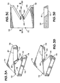
- FIGS. 5A-5D show a blade 100 according to the present invention with a body 100 a ; opposed inclined faces 101 , 102 ; opposed inclined faces 103 , 104 ; and opposed inclined end portions 105 , 106 .
- Projections 107 , 108 are formed between faces 101 , 103 and 104 , 102 , respectively.
- the blade 100 has a base 109 .
- Projection 107 has an edge 107 a and projection 108 has an edge 108 a.
- FIGS. 6A-6D show a blade 110 according to the present invention with a body 110 a , two inclined faces 111 , 112 ; two opposed inclined faces 113 , 114 ; inclined end portions 115 , 116 ; a central semicircular inclined face 117 ; and a base 110 b .
- Projections 118 , 119 are formed between faces 111 , 113 and 114 , 112 , respectively.
- Projection 118 has an edge 118 a and projection 119 has an edge 119 a.
- FIGS. 7A-7D show a blade 120 according to the present invention which has a body 122 ; a base 124 ; opposed inclined faces 126 , 128 ; inclined faces 132 , 134 ; inclined end portions 136 , 138 ; and a semicircular inclined face 130 .
- a serrated cutting surface 125 extends around a lower edge 127 of the face 130 and extends partially onto the faces 126 , 128 . As shown the serrations of the surface 125 have pointed tips 129 ; but, optionally, these tips may be rounded off.
- the faces 126 , 132 are at an angle to each other forming a projection 131 with an edge 135 .
- the faces 128 , 134 are at an angle to each other forming the projection 133 with an edge 137 .
- FIGS. 8A-8D show a blade 140 according to the present invention which has a body 142 ; a base 144 ; opposed inclined faces 146 , 148 ; a projection 150 between the faces 146 , 148 ; and inclined end portions 156 , 158 .
- the projection 150 has inclined faces 151 , 152 and a center face 153 .
- a projection 155 is formed between the faces 156 , 146 having an edge 154 .
- a projection 157 is formed between the faces 148 , 158 having an edge 159 .
- the projection 150 is rounded off.
- FIGS. 9A-9D show a blade 160 according to the present invention which has a body 162 ; a base 164 ; opposed inclined faces 172 , 173 ; inclined end portions 171 , 174 ; projections 181 , 182 ; and a recess 180 formed between the projections 181 , 182 .
- a projection 161 with an edge 163 is formed between the face 172 and the end portion 171 .
- a projection 165 with an edge 167 is formed between the face 173 and the end portion 174 .
- the projection 181 has inclined faces 183 , 185 and an inclined center portion 184 .
- the projection 182 has inclined faces 186 , 188 and an inclined center portion 187 .
- the projections 181 , 182 are rounded off.
- FIG. 10 shows an apparatus 200 for severing a tubular (e.g., but not limited to, drill pipe, drill collar, casing, riser, tubing, and drill pipe tool joints—as is true and can be accomplished with any apparatus herein according to the present invention and with any blade or blades according to the present invention).
- the apparatus 200 has two alternately movable sets of rams 201 , 202 and 203 , 204 .
- each ram 201 , 202 has a plurality of spaced-apart puncturing points 206 which make a series of corresponding spaced apart holes in a tubular, thereby weakening the tubular and facilitating its complete shearing by blades 208 (any according to the present invention or any known blade) of the rams 203 , 204 .
- FIG. 11 shows an apparatus 220 according to the present invention which has two sets of movable rams 221 , 222 and 223 , 224 .
- Rams 221 , 222 have flat faces 228 which are used to flatten a tubular 229 (“flatten” means make non-round to any extent as compared to the original round shape of the tubular 229 and includes, but it not limited to, a substantially or totally flattened tubular), e.g. as shown by the dotted line in FIG. 11 .
- the tubular 229 is completely severed by blades 225 , 226 on the rams 223 , 224 , respectively.
- the blades 225 , 226 may be any blade according to the present invention or any known blade.
- FIG. 12 illustrates a method for severing a tubular 230 by either applying tension T to the tubular lengthwise with a tension applying apparatus TA, shown schematically (see arrows T) or by applying compression to it with a compression applying apparatus CA shown schematically (see arrows C).
- Ram apparatuses 231 , 232 with blades 233 , 234 respectively of a blowout preventer 235 are movable to sever the tubular 230 .
- a tensioning step or steps and/or a compression step or steps may be used with any method according to the present invention, including but not limited to, methods as illustrated in FIGS. 10-15 .
- FIG. 13 illustrates a method according to the present invention in which torque is applied to a tubular 240 while it is severed with blades 242 , 243 (any blade or blades according to the present invention) of movable ram apparatuses 244 , 245 of a blowout preventer 246 .
- Rotation of the tubular 240 can be accomplished by any suitable rotating apparatus above, adjacent, and/or below the tubular, e.g. an apparatus RA (shown schematically in FIG. 13 ).
- a torquing step or steps may be used with any method according to the present invention.
- FIG. 14 illustrates a method according to the present invention for either severing a tubular 254 with blades 255 on movable rams 256 within a blowout preventer apparatus 250 using controlled explosive charges 252 in or on movable bodies 253 ; or a method for weakening a tubular at specific desired locations to facilitate complete severing of the tubular by blade(s) according to the present invention.
- the charges 252 are mounted on the blades 255 or on the rams 256 .
- One, two, three, four or more charges may be used. Any blade according to the present invention or any known blades may be used.
- FIGS. 15A-15H illustrate a method according to the present invention using a blowout preventer 300 (depicted schematically, FIG. 15B ) according to the present invention (e.g. as any disclosed herein) with movable rams R (shown schematically, FIG. 15B ) with blades 301 , 302 (blade 301 like blade 302 ; blade 302 inverted with respect to blade 301 —as may be the case with any two blades of any apparatus disclosed herein).
- Each blade 301 , 302 has a body 304 and a central projection 310 with a pointed member 312 and cutting portions 313 , 314 .
- Each projection 310 has cutting surfaces 310 a and 310 b .
- the cutting surfaces are sloped from the vertical and the projections 310 have cutting surfaces at an angle to each other.
- the rams R move the blades so that, initially, the projections 310 contact and puncture a tubular T (e.g. casing, drill pipe, tool joints, drill collars, etc.) and then, following movement of the projections into the tubular T and cutting of the tubular T by the projections 310 and the cutting portions 313 , 314 , complete severing of the tubular T.
- the projections 310 are diametrically opposed so that the outermost point of the projections (and then the remainder of the projections) push against each other facilitating puncturing of the tubular and then severing of the tubular.
- This use of dual opposed puncturing projections also serves to maintain the tubular in a desired location within the blowout preventer 300 during severing so that puncturing and severing proceed with the blades 301 , 302 maintained in a desired relation with respect to the tubular T.
- FIG. 15B illustrates initial entry of the points 312 into the tubular T.
- FIG. 15D illustrates further inward progress of the points 312 and further separation of the tubular portions T 1 , T 2 and T 3 , T 4 .
- the cutting surfaces 313 and 314 begin to cut the tubular T.
- the projections 310 cut an amount of the tubular T and the cutting surfaces 313 , 314 (and the projections 310 as they progress through the tubular) need cut only the remaining portion of the tubular T to effect complete severing of the tubular T. In certain aspects, and depending on the size of the tubular, the projections 310 can cut the entire tubular.
- FIG. 15G shows the tubular T completely severed.
- only one blade 301 or 302 is used and the other blade has no projection or projections.
- one blade be inverted with respect to an opposite blade.
- cutting surfaces adjacent a cutting projection either cut no tubular at all or only need cut only a fraction of a total wall thickness, circumference of a tubular (unlike, e.g., certain prior “V shear” or “V-shaped” blades in which each cutting surface cuts a much large portion of a tubular).
- any blade according to the present invention or any prior blade or part thereof, and/or cutting surfaces thereof, and/or top and/or bottom thereof, and/or a tubular-puncturing part thereof with a low friction coating, e.g., but not limited to, polytetrafluoroethylene coating, electroless nickel coating, and/or titanium/nickel coating, including but not limited to, low friction coatings applied by a physical vapor deposition (“PVD”) process.
- PVD physical vapor deposition
- Such coatings are shown, e.g., as a coating 69 ( FIG. 2A ) and a coating 209 ( FIG. 10 ) and as a coating 79 ( FIG. 3A ) on the top of a blade and as a coating 75 ( FIG. 3A ) on the bottom of a blade, applied by any suitable method or process.
- These coatings may be applied to any suitable known thickness for the application of low friction coatings.
- the present invention therefore, provides in some, but not in necessarily all, embodiments a blowout preventer with a body with a top, a bottom, and a bore therethrough from the top to the bottom, ram apparatus movable within the body, the ram apparatus including two ram blocks each with a cutting blade according to the present invention.
- the present invention therefore, provides in at least some embodiments, methods for using a blowout preventer according to the present invention.
- the present invention therefore, provides in certain, but not necessarily all embodiments, method including inserting a tubular into a tubular severing apparatus (the apparatus including a first member movable toward the tubular, a second member movable toward the tubular to be severed, the second member disposed opposite to the first member, a first blade on the first member, the first blade comprising a first blade body, a first projection projecting from the first blade body, a first point structure on the first projection for contacting and puncturing the tubular, first projection cutting surfaces on the first projection defining the first point structure and for cutting the tubular, and the first point structure projecting sufficiently from the first blade body so that the first projection can contact the tubular and puncture the tubular before any other part of the first blade body contacts the tubular, and a second blade on the second member); moving the first blade toward the tubular to bring the first point structure into contact with an outer surface of the tubular; moving the first blade so that the first point structure punctures into the tubular and goes through the tubular; moving the first blade
- Such a method may include one or some, in any possible combination, of the following: wherein the tubular severing apparatus's second blade has a second blade body, a second projection projecting from the second blade body, a second point structure on the second projection for contacting and puncturing the tubular, a second projection cutting surfaces on the second projection defining the point structure and for cutting the tubular, and the second point structure projecting sufficiently from the second blade body so that the second projection can contact the tubular and puncture the tubular before any other part of the second blade body contacts the tubular, the method including moving the second blade toward the tubular as the first blade is moved toward the tubular and moving the second blade so that the second point structure contacts an outer surface of the tubular, moving the second blade so that the second point structure punctures into the tubular and goes through the tubular, and moving the second blade to cut a portion of the tubular with the second projection cutting surfaces; wherein the tubular is severed by the projection cutting surfaces of the first blade and of the second blade; wherein the first blade further comprises first blade cutting
- the present invention therefore, provides in certain, but not necessarily all embodiments, a method for severing a tubular, the tubular useful for well bore operations, the method including: inserting a tubular into a tubular severing apparatus (the apparatus having a first member movable toward the tubular, a second member movable toward the tubular to be severed, the second member disposed opposite to the first member, a first blade on the first member, the first blade comprising a first blade body, a first projection projecting from the first blade body, a first point structure on the first projection for contacting and puncturing the tubular, first projection cutting surfaces on the first projection defining the first point structure and for cutting the tubular, and the first point structure projecting sufficiently from the first blade body so that the first projection can contact the tubular and puncture the tubular before any other part of the first blade body contacts the tubular, and a second blade on the second member); moving the first blade toward the tubular to bring the first point structure into contact with an outer surface of the tubular; moving the first
- a tubular severing apparatus for severing a tubular used in well bore operations, the apparatus including: a first member movable toward a tubular to be severed, the tubular comprising a well bore operations tubular; a second member movable toward the tubular to be severed, the second member disposed opposite to the first member; a first blade on the first member, the first blade including a blade body, a projection projecting from a center of the blade body, point structure on the projection for contacting and puncturing the tubular, projection cutting surfaces on the projection defining the point structure and for cutting the tubular, and the point structure projecting sufficiently from the blade body and the projection movable to contact the tubular and puncture the tubular before any other part of the blade body contacts the tubular; and, in one aspect, the second blade like the first blade.
Abstract
Description
Claims (19)
Priority Applications (6)
| Application Number | Priority Date | Filing Date | Title |
|---|---|---|---|
| US12/883,469 US8066070B2 (en) | 2006-04-25 | 2010-09-16 | Blowout preventers and methods of use |
| US13/118,289 US8720565B2 (en) | 2006-04-25 | 2011-05-27 | Tubular severing system and method of using same |
| US13/118,252 US8720564B2 (en) | 2006-04-25 | 2011-05-27 | Tubular severing system and method of using same |
| US13/118,200 US8424607B2 (en) | 2006-04-25 | 2011-05-27 | System and method for severing a tubular |
| US13/236,490 US8720567B2 (en) | 2006-04-25 | 2011-09-19 | Blowout preventers for shearing a wellbore tubular |
| US13/236,504 US8602102B2 (en) | 2006-04-25 | 2011-09-19 | Blowout preventers and methods of use |
Applications Claiming Priority (3)
| Application Number | Priority Date | Filing Date | Title |
|---|---|---|---|
| US11/411,203 US7367396B2 (en) | 2006-04-25 | 2006-04-25 | Blowout preventers and methods of use |
| US12/151,279 US7814979B2 (en) | 2006-04-25 | 2008-05-05 | Blowout preventers and methods of use |
| US12/883,469 US8066070B2 (en) | 2006-04-25 | 2010-09-16 | Blowout preventers and methods of use |
Related Parent Applications (1)
| Application Number | Title | Priority Date | Filing Date |
|---|---|---|---|
| US12/151,279 Continuation US7814979B2 (en) | 2006-04-25 | 2008-05-05 | Blowout preventers and methods of use |
Related Child Applications (5)
| Application Number | Title | Priority Date | Filing Date |
|---|---|---|---|
| US13/118,200 Continuation-In-Part US8424607B2 (en) | 2006-04-25 | 2011-05-27 | System and method for severing a tubular |
| US13/118,252 Continuation-In-Part US8720564B2 (en) | 2006-04-25 | 2011-05-27 | Tubular severing system and method of using same |
| US13/118,289 Continuation-In-Part US8720565B2 (en) | 2006-04-25 | 2011-05-27 | Tubular severing system and method of using same |
| US13/236,504 Division US8602102B2 (en) | 2006-04-25 | 2011-09-19 | Blowout preventers and methods of use |
| US13/236,490 Continuation US8720567B2 (en) | 2006-04-25 | 2011-09-19 | Blowout preventers for shearing a wellbore tubular |
Publications (2)
| Publication Number | Publication Date |
|---|---|
| US20110000670A1 US20110000670A1 (en) | 2011-01-06 |
| US8066070B2 true US8066070B2 (en) | 2011-11-29 |
Family
ID=37835262
Family Applications (5)
| Application Number | Title | Priority Date | Filing Date |
|---|---|---|---|
| US11/411,203 Active 2026-06-20 US7367396B2 (en) | 2006-04-25 | 2006-04-25 | Blowout preventers and methods of use |
| US12/151,279 Active US7814979B2 (en) | 2006-04-25 | 2008-05-05 | Blowout preventers and methods of use |
| US12/883,469 Active US8066070B2 (en) | 2006-04-25 | 2010-09-16 | Blowout preventers and methods of use |
| US13/236,504 Active US8602102B2 (en) | 2006-04-25 | 2011-09-19 | Blowout preventers and methods of use |
| US13/236,490 Active US8720567B2 (en) | 2006-04-25 | 2011-09-19 | Blowout preventers for shearing a wellbore tubular |
Family Applications Before (2)
| Application Number | Title | Priority Date | Filing Date |
|---|---|---|---|
| US11/411,203 Active 2026-06-20 US7367396B2 (en) | 2006-04-25 | 2006-04-25 | Blowout preventers and methods of use |
| US12/151,279 Active US7814979B2 (en) | 2006-04-25 | 2008-05-05 | Blowout preventers and methods of use |
Family Applications After (2)
| Application Number | Title | Priority Date | Filing Date |
|---|---|---|---|
| US13/236,504 Active US8602102B2 (en) | 2006-04-25 | 2011-09-19 | Blowout preventers and methods of use |
| US13/236,490 Active US8720567B2 (en) | 2006-04-25 | 2011-09-19 | Blowout preventers for shearing a wellbore tubular |
Country Status (12)
| Country | Link |
|---|---|
| US (5) | US7367396B2 (en) |
| EP (4) | EP2363572A1 (en) |
| CN (1) | CN101427003B (en) |
| AT (1) | ATE511596T1 (en) |
| AU (1) | AU2006342770A1 (en) |
| BR (1) | BRPI0621572A2 (en) |
| CA (3) | CA2747138C (en) |
| DK (2) | DK2400109T3 (en) |
| NO (3) | NO340135B1 (en) |
| PL (3) | PL2013443T3 (en) |
| RU (1) | RU2401935C2 (en) |
| WO (1) | WO2007122365A1 (en) |
Cited By (19)
| Publication number | Priority date | Publication date | Assignee | Title |
|---|---|---|---|---|
| US20110048185A1 (en) * | 2009-09-03 | 2011-03-03 | Hydril Usa Manufacturing Llc | Method and Systems for Using a Shim Plate for Increased Strength |
| US20110226476A1 (en) * | 2006-04-25 | 2011-09-22 | National Oilwell Varco, L.P. | Tubular severing system and method of using same |
| US20110226477A1 (en) * | 2006-04-25 | 2011-09-22 | National Oilwell Varco, L.P. | Tubular severing system and method of using same |
| US20120006529A1 (en) * | 2006-04-25 | 2012-01-12 | Frank Benjamin Springett | Blowout preventers and methods of use |
| US20120138159A1 (en) * | 2010-12-06 | 2012-06-07 | Hydril Usa Manufacturing Llc | Rechargeable System for Subsea Force Generating Device and Method |
| US20120193556A1 (en) * | 2011-02-02 | 2012-08-02 | Hydril Usa Manufacturing Llc | Shear Blade Geometry and Method |
| US8424607B2 (en) | 2006-04-25 | 2013-04-23 | National Oilwell Varco, L.P. | System and method for severing a tubular |
| US8464785B2 (en) * | 2011-06-14 | 2013-06-18 | Hydril Usa Manufacturing Llc | Pipe guide arms for blind shear rams |
| US20130233144A1 (en) * | 2009-09-16 | 2013-09-12 | II Woodrow A. Powers | Knife assembly for a trimming machine |
| US8540017B2 (en) | 2010-07-19 | 2013-09-24 | National Oilwell Varco, L.P. | Method and system for sealing a wellbore |
| US8544538B2 (en) | 2010-07-19 | 2013-10-01 | National Oilwell Varco, L.P. | System and method for sealing a wellbore |
| US8632047B2 (en) | 2011-02-02 | 2014-01-21 | Hydril Usa Manufacturing Llc | Shear blade geometry and method |
| US8794308B1 (en) * | 2013-07-21 | 2014-08-05 | Milanovich Investments, L.L.C. | Blowout preventer and flow regulator |
| US8844898B2 (en) | 2009-03-31 | 2014-09-30 | National Oilwell Varco, L.P. | Blowout preventer with ram socketing |
| US8978751B2 (en) | 2011-03-09 | 2015-03-17 | National Oilwell Varco, L.P. | Method and apparatus for sealing a wellbore |
| US20160221202A1 (en) * | 2015-02-02 | 2016-08-04 | Jorson & Carlson | Coated and recessed industrial paper knife |
| US10000987B2 (en) | 2013-02-21 | 2018-06-19 | National Oilwell Varco, L.P. | Blowout preventer monitoring system and method of using same |
| US11286740B2 (en) * | 2019-04-21 | 2022-03-29 | Schlumberger Technology Corporation | Blowout preventer shearing ram |
| US11391108B2 (en) | 2020-06-03 | 2022-07-19 | Schlumberger Technology Corporation | Shear ram for a blowout preventer |
Families Citing this family (76)
| Publication number | Priority date | Publication date | Assignee | Title |
|---|---|---|---|---|
| US20080105436A1 (en) * | 2006-11-02 | 2008-05-08 | Schlumberger Technology Corporation | Cutter Assembly |
| US20080282857A1 (en) * | 2007-05-16 | 2008-11-20 | Khoury John J | Cutting machine for use in removing damaged oilfield rigs and equipment located in offshore waters, and method of using same |
| US20120291606A1 (en) * | 2007-05-16 | 2012-11-22 | Khoury John J | Tubular cutting apparatus |
| US20170282263A1 (en) * | 2007-05-16 | 2017-10-05 | John J. Khoury | Tubular cutting apparatus |
| CN101519952A (en) * | 2008-02-25 | 2009-09-02 | 普拉德研究及开发股份有限公司 | Knife tool component |
| US8567490B2 (en) * | 2009-06-19 | 2013-10-29 | National Oilwell Varco, L.P. | Shear seal blowout preventer |
| US8720584B2 (en) | 2011-02-24 | 2014-05-13 | Foro Energy, Inc. | Laser assisted system for controlling deep water drilling emergency situations |
| US8684088B2 (en) | 2011-02-24 | 2014-04-01 | Foro Energy, Inc. | Shear laser module and method of retrofitting and use |
| US9845652B2 (en) | 2011-02-24 | 2017-12-19 | Foro Energy, Inc. | Reduced mechanical energy well control systems and methods of use |
| US8783360B2 (en) | 2011-02-24 | 2014-07-22 | Foro Energy, Inc. | Laser assisted riser disconnect and method of use |
| US8783361B2 (en) | 2011-02-24 | 2014-07-22 | Foro Energy, Inc. | Laser assisted blowout preventer and methods of use |
| US8573598B2 (en) * | 2009-09-17 | 2013-11-05 | Diamond Power International, Inc. | Sootblower isolation wall box |
| US8225857B2 (en) * | 2009-11-25 | 2012-07-24 | Hydril Usa Manufacturing Llc | Breech lock mechanisms for blowout preventer and method |
| US8439327B2 (en) * | 2009-12-21 | 2013-05-14 | Hydril Usa Manufacturing Llc | Shear block and blade interface and method |
| AU2011256976B2 (en) * | 2010-05-28 | 2015-05-21 | National Oilwell Varco, L.P. | Tubular severing system and method of using same |
| US8162046B2 (en) | 2010-08-17 | 2012-04-24 | T-3 Property Holdings, Inc. | Blowout preventer with shearing blades |
| BR112013006291A2 (en) * | 2010-09-17 | 2016-06-07 | Nat Oilwell Varco Lp | tool joint, system, and method for forming a hard belt in a down hole tool |
| US9022104B2 (en) | 2010-09-29 | 2015-05-05 | National Oilwell Varco, L.P. | Blowout preventer blade assembly and method of using same |
| GB2502898B (en) * | 2011-01-04 | 2014-12-24 | Aker Subsea As | Gate Valve Assembly |
| US9045961B2 (en) | 2011-01-31 | 2015-06-02 | National Oilwell Varco, L.P. | Blowout preventer seal and method of using same |
| NO332669B1 (en) * | 2011-05-16 | 2012-12-03 | Smart Installations As | Cutting device, safety valve, method and applications for cutting a rudder-related object in a well safety valve |
| WO2012170811A1 (en) * | 2011-06-08 | 2012-12-13 | Axon Ep, Inc. | Improved blowout preventer |
| WO2013002971A2 (en) | 2011-06-29 | 2013-01-03 | National Oilwell Varco, L.P. | Blowout preventer seal assembly and method of using same |
| US20130153204A1 (en) * | 2011-12-20 | 2013-06-20 | Hydril Usa Manufacturing Llc | Ram bop shear blade process to enhance the toughness |
| US9074450B2 (en) | 2012-02-03 | 2015-07-07 | National Oilwell Varco, L.P. | Blowout preventer and method of using same |
| US9068423B2 (en) | 2012-02-03 | 2015-06-30 | National Oilwell Varco, L.P. | Wellhead connector and method of using same |
| US20140182441A1 (en) * | 2012-03-23 | 2014-07-03 | Philip J Pisczak | Cutter dies |
| CA2868519C (en) | 2012-04-05 | 2017-02-14 | National Oilwell Varco, L.P. | Wellsite connector with piston driven collets and method of using same |
| BR112014025159B1 (en) | 2012-04-10 | 2020-12-08 | National Oicwel L Varco, L.P | lock assembly for a rash preventative controller, and method for locking a rash preventative controller |
| US9175541B2 (en) | 2012-04-10 | 2015-11-03 | National Oilwell Varco, L.P. | Blowout preventer seal assembly and method of using same |
| US20140048245A1 (en) * | 2012-08-16 | 2014-02-20 | Hydril Usa Manufacturing Llc | Replaceable Wear Plates for Use with Blind Shear Rams |
| WO2014085628A2 (en) | 2012-11-29 | 2014-06-05 | National Oilwell Varco, L.P. | Blowout preventer monitoring system and method of using same |
| US20140209314A1 (en) * | 2013-01-28 | 2014-07-31 | Schlumberger Technology Corporation | Shear and seal system for subsea applications |
| EP2971466B1 (en) * | 2013-03-15 | 2017-01-04 | FMC Technologies, Inc. | Gate valve assembly comprising a support member |
| US9249643B2 (en) | 2013-03-15 | 2016-02-02 | National Oilwell Varco, L.P. | Blowout preventer with wedge ram assembly and method of using same |
| US9394758B2 (en) | 2013-05-03 | 2016-07-19 | National Oilwell Varco, L.P. | Sealable wellsite valve and method of using same |
| GB201310613D0 (en) * | 2013-06-14 | 2013-07-31 | Enovate Systems Ltd | Well bore control system |
| CN104234652A (en) * | 2013-06-18 | 2014-12-24 | 中国石油天然气股份有限公司 | Movable-type oil tube and sucker rod shearing device |
| BR112015032265B1 (en) | 2013-06-24 | 2022-01-04 | National Oilwell Varco, L.P. | ACTIVATOR FOR A PREVENTIVE BURST CONTROLLER, AND, METHOD TO ACTIVATE A PREVENTIVE BURST CONTROLLER |
| US8794333B1 (en) * | 2013-07-02 | 2014-08-05 | Milanovich Investments, L.L.C. | Combination blowout preventer and recovery device |
| US8727018B1 (en) | 2013-07-19 | 2014-05-20 | National Oilwell Varco, L.P. | Charging unit, system and method for activating a wellsite component |
| CN103692465B (en) * | 2013-12-12 | 2015-12-02 | 中煤邯郸特殊凿井有限公司 | A kind of plastic pipe cutter |
| US9631442B2 (en) * | 2013-12-19 | 2017-04-25 | Weatherford Technology Holdings, Llc | Heave compensation system for assembling a drill string |
| US9828823B2 (en) * | 2014-04-01 | 2017-11-28 | Cameron International Corporation | Rod hang-off system |
| WO2015163879A1 (en) | 2014-04-24 | 2015-10-29 | Halliburton Energy Services, Inc. | Multi-perforating tool |
| EP2995768B1 (en) * | 2014-09-12 | 2020-01-22 | Cameron Technologies Limited | Blowout preventer with blade including multiple profiles |
| US11156055B2 (en) | 2014-10-20 | 2021-10-26 | Worldwide Oilfield Machine, Inc. | Locking mechanism for subsea compact cutting device (CCD) |
| US9732576B2 (en) * | 2014-10-20 | 2017-08-15 | Worldwide Oilfield Machine, Inc. | Compact cutting system and method |
| US10954738B2 (en) | 2014-10-20 | 2021-03-23 | Worldwide Oilfield Machine, Inc. | Dual compact cutting device intervention system |
| US10655421B2 (en) * | 2014-10-20 | 2020-05-19 | Worldwide Oilfield Machine, Inc. | Compact cutting system and method |
| WO2016090334A1 (en) | 2014-12-05 | 2016-06-09 | National Oilwell Varco, L.P. | Method of closing a blowout preventer seal based on seal erosion |
| US9441443B2 (en) | 2015-01-27 | 2016-09-13 | National Oilwell Varco, L.P. | Compound blowout preventer seal and method of using same |
| EP3256691A1 (en) | 2015-02-13 | 2017-12-20 | National Oilwell Varco, L.P. | A detection system for a wellsite and method of using same |
| US9879498B2 (en) * | 2015-04-21 | 2018-01-30 | Axon Pressure Products, Inc. | Shear block design for blowout preventer |
| US10233716B2 (en) | 2015-09-01 | 2019-03-19 | Cameron International Corporation | Blowout preventer including blind seal assembly |
| US10167695B2 (en) | 2015-11-09 | 2019-01-01 | Cameron International Corporation | Blowout preventer including shear body |
| NO343423B1 (en) * | 2015-12-11 | 2019-03-04 | Smart Installations As | Mobile cutting tool and method for cutting a subsea tubular structure |
| CN108699897B (en) * | 2016-01-05 | 2021-01-12 | 诺布尔钻井服务股份有限公司 | Pressure assisted motor operated ram actuator for well pressure control devices |
| US9938794B2 (en) * | 2016-06-21 | 2018-04-10 | Bop Technologies, Llc | Guided locking ram blocks |
| BR112019004690B1 (en) | 2016-09-12 | 2022-12-20 | Kinetic Pressure Control, Ltd | PREVENTIVE ERUPTION CONTROLLER AND METHOD FOR CLOSING A THROUGH HOLE |
| US10577884B2 (en) * | 2017-03-31 | 2020-03-03 | General Electric Company | Blowout prevention system including blind shear ram |
| NO343501B1 (en) * | 2017-06-16 | 2019-03-25 | Nor Oil Tools As | Tool for cutting well pipes |
| CN108104761B (en) * | 2018-01-17 | 2020-06-23 | 东营市元捷石油机械有限公司 | Using method of circular shearing device for coiled tubing four-ram blowout preventer |
| CN108286419B (en) * | 2018-01-17 | 2020-12-22 | 宋协翠 | Circular shearing device for coiled tubing four-ram blowout preventer |
| BR112020005954A2 (en) * | 2018-04-03 | 2020-10-20 | Kinetic Pressure Control, Ltd. | Blowout preventer and method for closing a well |
| CA3114710A1 (en) * | 2018-10-26 | 2020-04-30 | Kinetic Pressure Control, Ltd. | Pressure control device with safety locking mechanism |
| CN109267960A (en) * | 2018-11-29 | 2019-01-25 | 美钻深海能源科技研发(上海)有限公司 | A kind of urgent well shutdown apptss of explosive charge |
| WO2020219137A1 (en) * | 2019-04-21 | 2020-10-29 | Cameron International Corporation | Blowout preventer with multiple application ram blades |
| US20220356777A1 (en) * | 2019-04-21 | 2022-11-10 | Schlumberger Technology Corporation | Blowout Preventer Shearing Ram |
| BR112021021405A2 (en) * | 2019-04-26 | 2022-02-15 | Bobby Gallagher | Improved station maintenance and emergency disconnect capability for a vessel connected to a subsea well in shallow water |
| AU2020261348A1 (en) | 2019-04-26 | 2021-10-28 | Transocean Sedco Forex Ventures Limited | Improved station keeping and emergency disconnecting capability for a vessel connected to a subsea wellhead in shallow water |
| USD973734S1 (en) * | 2019-08-06 | 2022-12-27 | Nxl Technologies Inc. | Blind shear |
| WO2021030673A1 (en) * | 2019-08-15 | 2021-02-18 | Kinetic Pressure Control, Ltd. | Piston and gate assembly for kinetic pressure control apparatus ram |
| WO2021045985A1 (en) * | 2019-09-04 | 2021-03-11 | Kinetic Pressure Control, Ltd. | Kinetic shear ram cutters for well control apparatus |
| US10954737B1 (en) | 2019-10-29 | 2021-03-23 | Kongsberg Maritime Inc. | Systems and methods for initiating an emergency disconnect sequence |
| US11613955B2 (en) * | 2020-07-15 | 2023-03-28 | Baker Hughes Oilfield Operations Llc | Shear ram with vertical shear control |
Citations (150)
| Publication number | Priority date | Publication date | Assignee | Title |
|---|---|---|---|---|
| US2178698A (en) | 1936-05-04 | 1939-11-07 | Arthur J Penick | Tubing head |
| US2231613A (en) * | 1940-04-03 | 1941-02-11 | Paul Stock | Blowout preventer and control head |
| US2304793A (en) | 1941-06-09 | 1942-12-15 | Calpat Corp | Method of and apparatus for cutting pipe |
| US2592197A (en) | 1947-10-27 | 1952-04-08 | Jr Frank J Schweitzer | Side-plug hydraulic cellar gate |
| US2752119A (en) | 1952-03-24 | 1956-06-26 | Cameron Iron Works Inc | Blowout preventer |
| US3040611A (en) * | 1956-11-15 | 1962-06-26 | Duralumin | Guillotine shears |
| US3272222A (en) | 1963-10-28 | 1966-09-13 | Cameron Iron Works Inc | Blowout preventer |
| US3399728A (en) * | 1966-12-01 | 1968-09-03 | Allan R. Taylor | Conduit closure apparatus |
| US3554480A (en) * | 1968-01-16 | 1971-01-12 | Cameron Iron Works Inc | Blowout preventer |
| US3554278A (en) | 1969-07-31 | 1971-01-12 | Exxon Production Research Co | Pipe alignment apparatus |
| US3561526A (en) * | 1969-09-03 | 1971-02-09 | Cameron Iron Works Inc | Pipe shearing ram assembly for blowout preventer |
| US3647174A (en) | 1970-09-25 | 1972-03-07 | Hydril Co | Blowout preventer |
| US3670761A (en) | 1970-10-13 | 1972-06-20 | Hydril Co | Blowout preventer with resistance means between the body and the piston |
| US3716068A (en) * | 1971-06-11 | 1973-02-13 | F Addison | Surface controlled blowout arrester |
| US3741296A (en) | 1971-06-14 | 1973-06-26 | Hydril Co | Replacement of sub sea blow out preventer packing units |
| US3744749A (en) | 1971-05-18 | 1973-07-10 | Hydril Co | Blowout preventer with ram support and guide means |
| US3766979A (en) | 1972-04-20 | 1973-10-23 | J Petrick | Well casing cutter and sealer |
| US3863667A (en) * | 1973-03-21 | 1975-02-04 | Pipe Line Development Co | Combined shear head and housing plug |
| US3918478A (en) | 1974-02-11 | 1975-11-11 | Hydril Co | Blowout preventer with locking means |
| US3922780A (en) * | 1974-11-04 | 1975-12-02 | Cyril Robert Green | Cable spearing and cutting apparatus |
| US3946806A (en) | 1972-06-16 | 1976-03-30 | Cameron Iron Works, Inc. | Ram-type blowout preventer |
| US3955622A (en) | 1975-06-09 | 1976-05-11 | Regan Offshore International, Inc. | Dual drill string orienting apparatus and method |
| US4007797A (en) | 1974-06-04 | 1977-02-15 | Texas Dynamatics, Inc. | Device for drilling a hole in the side wall of a bore hole |
| US4043389A (en) | 1976-03-29 | 1977-08-23 | Continental Oil Company | Ram-shear and slip device for well pipe |
| US4057887A (en) | 1974-05-06 | 1977-11-15 | Cameron Iron Works, Inc. | Pipe disconnecting apparatus |
| US4119115A (en) | 1976-03-19 | 1978-10-10 | British Gas Corporation | Stopping fluid flow in pipes |
| US4132265A (en) | 1978-04-06 | 1979-01-02 | Cameron Iron Works, Inc. | Pipe shearing ram assembly for blowout preventer |
| US4132267A (en) | 1978-04-06 | 1979-01-02 | Cameron Iron Works, Inc. | Pipe shearing ram assembly for blowout preventer |
| US4140041A (en) * | 1976-04-29 | 1979-02-20 | Commissariat A L'energie Atomique | Explosive-forming device for the obturation of a pipe by compression |
| US4215749A (en) | 1979-02-05 | 1980-08-05 | Acf Industries, Incorporated | Gate valve for shearing workover lines to permit shutting in of a well |
| US4220206A (en) | 1979-01-22 | 1980-09-02 | Winkle Denzal W Van | Quick opening closure arrangement for well completions |
| US4253638A (en) | 1979-08-02 | 1981-03-03 | Cameron Iron Works, Inc. | Blowout preventer |
| US4313496A (en) * | 1980-04-22 | 1982-02-02 | Cameron Iron Works, Inc. | Wellhead shearing apparatus |
| US4341264A (en) | 1980-10-15 | 1982-07-27 | Cameron Iron Works, Inc. | Wellhead shearing apparatus |
| US4347898A (en) | 1980-11-06 | 1982-09-07 | Cameron Iron Works, Inc. | Shear ram blowout preventer |
| US4372527A (en) | 1980-05-05 | 1983-02-08 | Dresser Industries, Inc. | Blowout preventer |
| US4392633A (en) | 1979-10-29 | 1983-07-12 | Winkle Denzal W Van | Valve structure having movable seat means |
| US4416441A (en) | 1979-10-29 | 1983-11-22 | Winkle Denzal W Van | Blowout preventer |
| US4437643A (en) | 1981-06-25 | 1984-03-20 | Cameron Iron Works, Inc. | Ram-type blowout preventer |
| US4492359A (en) | 1982-06-25 | 1985-01-08 | Baugh Benton F | Valve assembly |
| US4504037A (en) | 1983-09-26 | 1985-03-12 | Hydril Company | Ram blowout preventer securing and retracting apparatus |
| US4508313A (en) * | 1982-12-02 | 1985-04-02 | Koomey Blowout Preventers, Inc. | Valves |
| US4516598A (en) | 1983-10-24 | 1985-05-14 | Stupak Adam E | Well safety valve |
| US4518144A (en) | 1983-09-01 | 1985-05-21 | Cameron Iron Works, Inc. | Ram-type blowout preventer and packer therefor |
| US4519577A (en) * | 1982-12-02 | 1985-05-28 | Koomey Blowout Preventers, Inc. | Flow controlling apparatus |
| US4523639A (en) * | 1983-11-21 | 1985-06-18 | Koomey Blowout Preventers, Inc. | Ram type blowout preventers |
| US4526339A (en) * | 1984-05-11 | 1985-07-02 | Universal Well Control Systems | Blowout preventer |
| US4537250A (en) * | 1983-12-14 | 1985-08-27 | Cameron Iron Works, Inc. | Shearing type blowout preventer |
| US4540046A (en) * | 1983-09-13 | 1985-09-10 | Nl Industries, Inc. | Shear ram apparatus |
| US4550895A (en) | 1984-09-24 | 1985-11-05 | Shaffer Donald U | Ram construction for oil well blow out preventer apparatus |
| US4558842A (en) | 1983-09-06 | 1985-12-17 | Bowen Tools, Inc. | Connector for joining blowout preventer members |
| US4612983A (en) | 1985-10-15 | 1986-09-23 | Gray Tool Company | Shear type gate valve |
| US4647002A (en) | 1983-09-23 | 1987-03-03 | Hydril Company | Ram blowout preventer apparatus |
| US4646825A (en) * | 1986-01-02 | 1987-03-03 | Winkle Denzal W Van | Blowout preventer, shear ram, shear blade and seal therefor |
| US4690411A (en) | 1985-12-23 | 1987-09-01 | Winkle Denzal W Van | Bonded mechanically inner connected seal arrangement for a blowout preventer |
| US4690033A (en) | 1985-12-16 | 1987-09-01 | Winkle Denzal W Van | Self actuating locking and unlocking arrangement and method for reciprocating piston type actuators |
| US4699350A (en) | 1985-04-04 | 1987-10-13 | TOTAL Compagnie Francaise de Petroles | Valve and a process for removing a closure member of the valve |
| US4923008A (en) * | 1989-01-16 | 1990-05-08 | Baroid Technology, Inc. | Hydraulic power system and method |
| US4923005A (en) | 1989-01-05 | 1990-05-08 | Otis Engineering Corporation | System for handling reeled tubing |
| US4943031A (en) | 1989-08-17 | 1990-07-24 | Drexel Oilfield Services, Inc. | Blowout preventer |
| US4969390A (en) | 1989-05-30 | 1990-11-13 | Cooper Industries, Inc. | Rod locking device |
| US5002130A (en) * | 1990-01-29 | 1991-03-26 | Otis Engineering Corp. | System for handling reeled tubing |
| US5013005A (en) * | 1986-04-18 | 1991-05-07 | Cameron Iron Works, Inc. | Blowout preventer |
| US5025708A (en) | 1990-01-30 | 1991-06-25 | Baroid Technology, Inc. | Actuator with automatic lock |
| US5056418A (en) | 1990-10-18 | 1991-10-15 | Granger Stanley W | Self-adjusting automatic locking piston for RAM blowout preventers |
| US5178215A (en) | 1991-07-22 | 1993-01-12 | Folsom Metal Products, Inc. | Rotary blowout preventer adaptable for use with both kelly and overhead drive mechanisms |
| US5199493A (en) * | 1991-05-03 | 1993-04-06 | Sodder George Jr | Methods and apparatus for shutting a conduit |
| US5217073A (en) * | 1991-05-07 | 1993-06-08 | Karsten Bruns | Cut-and-close device for pressure pipes in production and supply installations |
| US5237899A (en) * | 1991-08-08 | 1993-08-24 | General Electric Canada Inc. | Blade for cutting cylindrical structures |
| US5360061A (en) * | 1992-10-14 | 1994-11-01 | Womble Lee M | Blowout preventer with tubing shear rams |
| US5361832A (en) | 1993-06-17 | 1994-11-08 | Drexel Oilfield Services, Inc. | Annular packer and insert |
| US5400857A (en) * | 1993-12-08 | 1995-03-28 | Varco Shaffer, Inc. | Oilfield tubular shear ram and method for blowout prevention |
| US5505426A (en) | 1995-04-05 | 1996-04-09 | Varco Shaffer, Inc. | Hydraulically controlled blowout preventer |
| US5515916A (en) | 1995-03-03 | 1996-05-14 | Stewart & Stevenson Services, Inc. | Blowout preventer |
| US5566753A (en) | 1995-06-07 | 1996-10-22 | Drexel Oil Field Services, Inc. | Stripper/packer |
| US5575452A (en) | 1995-09-01 | 1996-11-19 | Varco Shaffer, Inc. | Blowout preventer with ram wedge locks |
| US5575451A (en) | 1995-05-02 | 1996-11-19 | Hydril Company | Blowout preventer ram for coil tubing |
| US5588491A (en) * | 1995-08-10 | 1996-12-31 | Varco Shaffer, Inc. | Rotating blowout preventer and method |
| US5590867A (en) | 1995-05-12 | 1997-01-07 | Drexel Oil Field Services, Inc. | Blowout preventer for coiled tubing |
| US5655745A (en) | 1995-01-13 | 1997-08-12 | Hydril Company | Low profile and lightweight high pressure blowout preventer |
| US5735502A (en) | 1996-12-18 | 1998-04-07 | Varco Shaffer, Inc. | BOP with partially equalized ram shafts |
| US5778918A (en) | 1996-10-18 | 1998-07-14 | Varco Shaffer, Inc. | Pilot valve with improved cage |
| US5863022A (en) | 1996-01-16 | 1999-01-26 | Van Winkle; D. Wayne | Stripper/packer and blowout preventer with split bonnet |
| US5897094A (en) | 1996-12-27 | 1999-04-27 | Varco Shaffer, Inc. | BOP with improved door connectors |
| US5918851A (en) | 1998-03-03 | 1999-07-06 | Cooper Cameron Corporation | Blowout preventer ram automatic locking system |
| US5961094A (en) | 1998-06-24 | 1999-10-05 | Tuboscope I/P Inc. | Method and apparatus for replacing a packer element |
| US6006647A (en) | 1998-05-08 | 1999-12-28 | Tuboscope I/P Inc. | Actuator with free-floating piston for a blowout preventer and the like |
| US6012528A (en) | 1998-06-24 | 2000-01-11 | Tuboscope I/P Inc. | Method and apparatus for replacing a packer element |
| US6016880A (en) | 1997-10-02 | 2000-01-25 | Abb Vetco Gray Inc. | Rotating drilling head with spaced apart seals |
| US6158505A (en) | 1999-08-30 | 2000-12-12 | Cooper Cameron Corporation | Blade seal for a shearing blind ram in a ram type blowout preventer |
| US6164619A (en) | 1999-01-07 | 2000-12-26 | Tuboscope I/P, Inc. | Bi-directional sealing ram |
| US6173770B1 (en) * | 1998-11-20 | 2001-01-16 | Hydril Company | Shear ram for ram-type blowout preventer |
| US6192680B1 (en) | 1999-07-15 | 2001-02-27 | Varco Shaffer, Inc. | Subsea hydraulic control system |
| US6244560B1 (en) | 2000-03-31 | 2001-06-12 | Varco Shaffer, Inc. | Blowout preventer ram actuating mechanism |
| US6244336B1 (en) * | 2000-03-07 | 2001-06-12 | Cooper Cameron Corporation | Double shearing rams for ram type blowout preventer |
| US6276450B1 (en) | 1999-05-02 | 2001-08-21 | Varco International, Inc. | Apparatus and method for rapid replacement of upper blowout preventers |
| US6374925B1 (en) | 2000-09-22 | 2002-04-23 | Varco Shaffer, Inc. | Well drilling method and system |
| US6484808B2 (en) | 2000-06-09 | 2002-11-26 | Varco I/P, Inc. | Stripper/packer |
| US6510897B2 (en) | 2001-05-04 | 2003-01-28 | Hydril Company | Rotational mounts for blowout preventer bonnets |
| US6530432B2 (en) * | 2001-07-11 | 2003-03-11 | Coiled Tubing Solutions, Inc. | Oil well tubing injection system and method |
| US6601650B2 (en) | 2001-08-09 | 2003-08-05 | Worldwide Oilfield Machine, Inc. | Method and apparatus for replacing BOP with gate valve |
| US6719042B2 (en) * | 2002-07-08 | 2004-04-13 | Varco Shaffer, Inc. | Shear ram assembly |
| US6718860B2 (en) | 2000-09-12 | 2004-04-13 | Denso Corporation | Method and apparatus for making holes in pipe |
| US6742597B2 (en) | 2002-05-20 | 2004-06-01 | Varco I/P | Safety check valve for coiled tubing |
| US20040124380A1 (en) | 2002-10-29 | 2004-07-01 | Van Winkle Denzal Wayne | Articulated slip ram for tapered coiled tubing |
| US6834721B2 (en) | 2002-01-14 | 2004-12-28 | Halliburton Energy Services, Inc. | System for disconnecting coiled tubing |
| US6843463B1 (en) | 2002-08-30 | 2005-01-18 | Varco I/P/ Inc. | Pressure regulated slip ram on a coil tubing blowout preventer |
| US6857634B2 (en) | 2003-02-20 | 2005-02-22 | Varco Shaffer, Inc. | BOP assembly with metal inserts |
| US6964303B2 (en) | 2000-02-16 | 2005-11-15 | Performance Research & Drilling, Llc | Horizontal directional drilling in wells |
| US6969042B2 (en) | 2004-05-01 | 2005-11-29 | Varco I/P, Inc. | Blowout preventer and ram actuator |
| US6974135B2 (en) | 2003-07-11 | 2005-12-13 | Varco I/P Inc. | Variable bore ram |
| US7011160B2 (en) * | 2001-11-26 | 2006-03-14 | Boyd Anthony R | High torque and high capacity rotatable center core with ram body assemblies |
| US7011159B2 (en) | 2003-09-16 | 2006-03-14 | Hydril Company, L.P. | Compact mid-grip fastener |
| US20060076526A1 (en) | 2004-10-13 | 2006-04-13 | Varco I/P, Inc. | Anodic Protective Seal in a Blowout Preventer |
| US7044430B2 (en) | 2004-04-30 | 2006-05-16 | Varco I/P, Inc. | Lock bars for blowout preventer |
| US7051990B2 (en) | 2004-07-01 | 2006-05-30 | Varco I/P, Inc. | Blowout preventer and movable bonnet support |
| US20060113501A1 (en) * | 2004-11-29 | 2006-06-01 | Isaacks C S | Shear/seal ram assembly for a ram-type blowout prevention system |
| US7055594B1 (en) | 2004-11-30 | 2006-06-06 | Varco I/P, Inc. | Pipe gripper and top drive systems |
| US20060137827A1 (en) | 2004-12-28 | 2006-06-29 | Fuji Photo Film Co., Ltd. | Guillotine cutter and tape affixing apparatus |
| US7086467B2 (en) * | 2001-12-17 | 2006-08-08 | Schlumberger Technology Corporation | Coiled tubing cutter |
| US7108081B2 (en) | 2003-12-31 | 2006-09-19 | Varco I/P, Inc. | Instrumented internal blowout preventer valve for measuring drill string drilling parameters |
| US7165619B2 (en) | 2002-02-19 | 2007-01-23 | Varco I/P, Inc. | Subsea intervention system, method and components thereof |
| US7195224B2 (en) | 2005-02-01 | 2007-03-27 | Varco I/P, Inc. | Blowout preventer and locking mechanism |
| US7207382B2 (en) * | 2004-07-27 | 2007-04-24 | Schaeper Gary R | Shearing sealing ram |
| US20070102655A1 (en) * | 2005-11-07 | 2007-05-10 | Springett Frank B | Blowout preventer with breech assembly |
| US20070137866A1 (en) | 2005-11-18 | 2007-06-21 | Ravensbergen John E | Dual purpose blow out preventer |
| US7234530B2 (en) * | 2004-11-01 | 2007-06-26 | Hydril Company Lp | Ram BOP shear device |
| US7270190B2 (en) | 2003-10-09 | 2007-09-18 | Varco I/P | Variable size coil tubing gripping elements |
| US7287544B2 (en) | 2003-10-21 | 2007-10-30 | Varco I/P, Inc. | Triple valve blow out preventer |
| US20080040070A1 (en) | 2006-08-11 | 2008-02-14 | Varco I/P, Inc. | Position Indicator for a Blowout Preventer |
| US7350587B2 (en) | 2004-11-30 | 2008-04-01 | Varco I/P, Inc. | Pipe guide |
| US7354026B2 (en) | 2004-08-17 | 2008-04-08 | Cameron International Corporation | Unitary blade seal for a shearing blind ram in a ram type blowout preventer |
| US7360603B2 (en) | 2004-11-30 | 2008-04-22 | Varco I/P, Inc. | Methods and apparatuses for wellbore operations |
| US7367396B2 (en) * | 2006-04-25 | 2008-05-06 | Varco I/P, Inc. | Blowout preventers and methods of use |
| US7389817B2 (en) * | 2002-01-16 | 2008-06-24 | Norsk Hydro Asa | Riser control device |
| US20080185046A1 (en) | 2007-02-07 | 2008-08-07 | Frank Benjamin Springett | Subsea pressure systems for fluid recovery |
| US20080189954A1 (en) * | 2006-04-04 | 2008-08-14 | Yung Sheng Lin | Pipe cutter |
| US20080265188A1 (en) | 2007-04-27 | 2008-10-30 | Frank Benjamin Springett | Ram locking blowout preventer |
| US20080267786A1 (en) | 2007-02-07 | 2008-10-30 | Frank Benjamin Springett | Subsea power fluid recovery systems |
| US7464765B2 (en) | 2005-08-24 | 2008-12-16 | National-Oilwell Dht, L.P. | Inner guide seal assembly and method for a ram type BOP system |
| US7487848B2 (en) | 2006-04-28 | 2009-02-10 | Varco I/P, Inc. | Multi-seal for top drive shaft |
| US20090056132A1 (en) | 2007-08-28 | 2009-03-05 | Darwell Industries Ltd. | Method of forming a blowout preventer body |
| US7520129B2 (en) | 2006-11-07 | 2009-04-21 | Varco I/P, Inc. | Subsea pressure accumulator systems |
| US7523644B2 (en) | 2005-09-08 | 2009-04-28 | Varco I/P | Method and apparatus for verifying the integrity of a joint seal |
| US20090205838A1 (en) | 2008-01-22 | 2009-08-20 | Frank Benjamin Springett | Wellbore continuous circulation systems |
| US20100038088A1 (en) | 2008-08-15 | 2010-02-18 | Frank Benjamin Springett | Multi-function multi-hole drilling rig |
| US7673674B2 (en) * | 2006-01-31 | 2010-03-09 | Stream-Flo Industries Ltd. | Polish rod clamping device |
| US7703739B2 (en) * | 2004-11-01 | 2010-04-27 | Hydril Usa Manufacturing Llc | Ram BOP shear device |
| US7726418B2 (en) | 2003-08-16 | 2010-06-01 | Coupler Development Limited | Method and apparatus for adding a tubular to drill string with diverter |
| US7748473B2 (en) | 2006-04-28 | 2010-07-06 | National Oilwell Varco, L.P. | Top drives with shaft multi-seal |
Family Cites Families (29)
| Publication number | Priority date | Publication date | Assignee | Title |
|---|---|---|---|---|
| US1161705A (en) | 1913-05-12 | 1915-11-23 | Elyria Iron & Steel Company | Mechanism for cutting tubing and the like into lengths. |
| US2555069A (en) | 1945-12-20 | 1951-05-29 | Verney Jean Louis Francois | Machine for cutting tubes and the like |
| US2596851A (en) * | 1950-02-27 | 1952-05-13 | Hansen John | Cutter blade |
| US2919111A (en) * | 1955-12-30 | 1959-12-29 | California Research Corp | Shearing device and method for use in well drilling |
| US3145462A (en) | 1961-05-01 | 1964-08-25 | Yoder Co | Method of severing tubes and reforming deformed portion caused by severing action |
| US3817326A (en) * | 1972-06-16 | 1974-06-18 | Cameron Iron Works Inc | Ram-type blowout preventer |
| US3863657A (en) * | 1973-05-23 | 1975-02-04 | Willard Irving | Dishwasher and sink combination |
| US4015496A (en) | 1976-02-06 | 1977-04-05 | Hill Engineering, Inc. | Dimpleless tube cutoff device |
| US4081027A (en) * | 1976-08-23 | 1978-03-28 | The Rucker Company | Shear rams for hydrogen sulfide service |
| US4132266A (en) * | 1978-04-06 | 1979-01-02 | Cameron Iron Works, Inc. | Pipe shearing ram assembly for blowout preventer |
| US4240503A (en) | 1979-05-01 | 1980-12-23 | Hydril Company | Blowout preventer shearing and sealing rams |
| JPS563128A (en) * | 1979-06-13 | 1981-01-13 | Yanagihara Kogyo Kk | Cutter for cutting pipe and preparation of pipe having concave arclike end surface |
| SU959935A1 (en) | 1980-12-30 | 1982-09-23 | Уральский ордена Трудового Красного Знамени политехнический институт им.С.М.Кирова | Working tool to die for cutting tubes |
| AU561397B2 (en) | 1981-10-07 | 1987-05-07 | Stuart Malcolm Harrison | Ram operated cutter (2 blades) |
| JPS59134918A (en) * | 1983-01-24 | 1984-08-02 | Toshiba Corp | Latch circuit |
| DE3516424A1 (en) | 1985-05-04 | 1986-11-06 | Moller, Falk von, Dipl.-Ing. (FH), 3100 Celle | Method and device for cutting through bars made of high-alloy steel |
| US5492541A (en) * | 1985-08-02 | 1996-02-20 | Clairol Incorporated | Dye compositions containing 5,6-dihydroxy indoles and a foam generator |
| CN1004217B (en) * | 1985-11-02 | 1989-05-17 | 阿茨国际器具公司 | Device and method for sectioning and recovery of seabed surface casing |
| US4987956A (en) * | 1989-08-30 | 1991-01-29 | Asger Hansen | Apparatus for use in drilling a well at an offshore location |
| US5158505A (en) * | 1990-10-25 | 1992-10-27 | Rexnord Corporation | Guide ring |
| US5350061A (en) * | 1994-01-21 | 1994-09-27 | Gunn Andrew L | Container systems for school supplies |
| US5713581A (en) | 1994-10-03 | 1998-02-03 | Hydril Company | Fibrous seal for blowout preventer |
| US5897074A (en) | 1996-07-30 | 1999-04-27 | Nuway Corporation | Moist tissue dispenser having sealing arms |
| US5833208A (en) | 1997-09-15 | 1998-11-10 | Jm Clipper Corporation | Inner seal for ram-type blowout preventer |
| AU2993999A (en) * | 1998-03-26 | 1999-10-18 | Hydril Company | Shear ram for ram-type blowout preventer |
| US6374928B1 (en) * | 2000-06-23 | 2002-04-23 | Vermeer Manufacturing Company | Method of blocking a pocket of a multi-pocket feed member for a directional drilling machine |
| US7181808B1 (en) * | 2006-05-31 | 2007-02-27 | Denzal Wayne Van Winkle | Buckle or clasp |
| US8632047B2 (en) * | 2011-02-02 | 2014-01-21 | Hydril Usa Manufacturing Llc | Shear blade geometry and method |
| US8505870B2 (en) | 2011-02-02 | 2013-08-13 | Hydril Usa Manufacturing Llc | Shear blade geometry and method |
-
2006
- 2006-04-25 US US11/411,203 patent/US7367396B2/en active Active
- 2006-12-27 PL PL06820703T patent/PL2013443T3/en unknown
- 2006-12-27 CN CN2006800543637A patent/CN101427003B/en active Active
- 2006-12-27 EP EP20110168306 patent/EP2363572A1/en not_active Withdrawn
- 2006-12-27 RU RU2008146406A patent/RU2401935C2/en active
- 2006-12-27 EP EP20060820703 patent/EP2013443B1/en active Active
- 2006-12-27 CA CA 2747138 patent/CA2747138C/en active Active
- 2006-12-27 WO PCT/GB2006/050478 patent/WO2007122365A1/en active Application Filing
- 2006-12-27 EP EP20110180811 patent/EP2400110B1/en active Active
- 2006-12-27 PL PL11180788T patent/PL2400109T3/en unknown
- 2006-12-27 DK DK11180788T patent/DK2400109T3/en active
- 2006-12-27 AU AU2006342770A patent/AU2006342770A1/en not_active Abandoned
- 2006-12-27 PL PL11180811T patent/PL2400110T3/en unknown
- 2006-12-27 DK DK06820703T patent/DK2013443T3/en active
- 2006-12-27 CA CA 2754716 patent/CA2754716C/en active Active
- 2006-12-27 CA CA 2649771 patent/CA2649771C/en active Active
- 2006-12-27 BR BRPI0621572-6A patent/BRPI0621572A2/en active IP Right Grant
- 2006-12-27 AT AT06820703T patent/ATE511596T1/en not_active IP Right Cessation
- 2006-12-27 EP EP20110180788 patent/EP2400109B1/en active Active
-
2008
- 2008-05-05 US US12/151,279 patent/US7814979B2/en active Active
- 2008-10-14 NO NO20084286A patent/NO340135B1/en unknown
-
2010
- 2010-09-16 US US12/883,469 patent/US8066070B2/en active Active
-
2011
- 2011-09-19 US US13/236,504 patent/US8602102B2/en active Active
- 2011-09-19 US US13/236,490 patent/US8720567B2/en active Active
- 2011-10-10 NO NO20111367A patent/NO340141B1/en unknown
-
2015
- 2015-03-02 NO NO20150275A patent/NO343971B1/en unknown
Patent Citations (166)
| Publication number | Priority date | Publication date | Assignee | Title |
|---|---|---|---|---|
| US2178698A (en) | 1936-05-04 | 1939-11-07 | Arthur J Penick | Tubing head |
| US2231613A (en) * | 1940-04-03 | 1941-02-11 | Paul Stock | Blowout preventer and control head |
| US2304793A (en) | 1941-06-09 | 1942-12-15 | Calpat Corp | Method of and apparatus for cutting pipe |
| US2592197A (en) | 1947-10-27 | 1952-04-08 | Jr Frank J Schweitzer | Side-plug hydraulic cellar gate |
| US2752119A (en) | 1952-03-24 | 1956-06-26 | Cameron Iron Works Inc | Blowout preventer |
| US3040611A (en) * | 1956-11-15 | 1962-06-26 | Duralumin | Guillotine shears |
| US3272222A (en) | 1963-10-28 | 1966-09-13 | Cameron Iron Works Inc | Blowout preventer |
| US3399728A (en) * | 1966-12-01 | 1968-09-03 | Allan R. Taylor | Conduit closure apparatus |
| US3554480A (en) * | 1968-01-16 | 1971-01-12 | Cameron Iron Works Inc | Blowout preventer |
| US3554278A (en) | 1969-07-31 | 1971-01-12 | Exxon Production Research Co | Pipe alignment apparatus |
| US3561526A (en) * | 1969-09-03 | 1971-02-09 | Cameron Iron Works Inc | Pipe shearing ram assembly for blowout preventer |
| US3647174A (en) | 1970-09-25 | 1972-03-07 | Hydril Co | Blowout preventer |
| US3670761A (en) | 1970-10-13 | 1972-06-20 | Hydril Co | Blowout preventer with resistance means between the body and the piston |
| US3744749A (en) | 1971-05-18 | 1973-07-10 | Hydril Co | Blowout preventer with ram support and guide means |
| US3716068A (en) * | 1971-06-11 | 1973-02-13 | F Addison | Surface controlled blowout arrester |
| US3741296A (en) | 1971-06-14 | 1973-06-26 | Hydril Co | Replacement of sub sea blow out preventer packing units |
| US3766979A (en) | 1972-04-20 | 1973-10-23 | J Petrick | Well casing cutter and sealer |
| US3946806A (en) | 1972-06-16 | 1976-03-30 | Cameron Iron Works, Inc. | Ram-type blowout preventer |
| US3863667A (en) * | 1973-03-21 | 1975-02-04 | Pipe Line Development Co | Combined shear head and housing plug |
| US3918478A (en) | 1974-02-11 | 1975-11-11 | Hydril Co | Blowout preventer with locking means |
| US4057887A (en) | 1974-05-06 | 1977-11-15 | Cameron Iron Works, Inc. | Pipe disconnecting apparatus |
| US4007797A (en) | 1974-06-04 | 1977-02-15 | Texas Dynamatics, Inc. | Device for drilling a hole in the side wall of a bore hole |
| US3922780A (en) * | 1974-11-04 | 1975-12-02 | Cyril Robert Green | Cable spearing and cutting apparatus |
| US3955622A (en) | 1975-06-09 | 1976-05-11 | Regan Offshore International, Inc. | Dual drill string orienting apparatus and method |
| US4119115A (en) | 1976-03-19 | 1978-10-10 | British Gas Corporation | Stopping fluid flow in pipes |
| US4043389A (en) | 1976-03-29 | 1977-08-23 | Continental Oil Company | Ram-shear and slip device for well pipe |
| US4140041A (en) * | 1976-04-29 | 1979-02-20 | Commissariat A L'energie Atomique | Explosive-forming device for the obturation of a pipe by compression |
| US4132267A (en) | 1978-04-06 | 1979-01-02 | Cameron Iron Works, Inc. | Pipe shearing ram assembly for blowout preventer |
| US4132265A (en) | 1978-04-06 | 1979-01-02 | Cameron Iron Works, Inc. | Pipe shearing ram assembly for blowout preventer |
| US4220206A (en) | 1979-01-22 | 1980-09-02 | Winkle Denzal W Van | Quick opening closure arrangement for well completions |
| US4215749A (en) | 1979-02-05 | 1980-08-05 | Acf Industries, Incorporated | Gate valve for shearing workover lines to permit shutting in of a well |
| US4253638A (en) | 1979-08-02 | 1981-03-03 | Cameron Iron Works, Inc. | Blowout preventer |
| US4392633A (en) | 1979-10-29 | 1983-07-12 | Winkle Denzal W Van | Valve structure having movable seat means |
| US4416441A (en) | 1979-10-29 | 1983-11-22 | Winkle Denzal W Van | Blowout preventer |
| US4313496A (en) * | 1980-04-22 | 1982-02-02 | Cameron Iron Works, Inc. | Wellhead shearing apparatus |
| US4372527A (en) | 1980-05-05 | 1983-02-08 | Dresser Industries, Inc. | Blowout preventer |
| US4341264A (en) | 1980-10-15 | 1982-07-27 | Cameron Iron Works, Inc. | Wellhead shearing apparatus |
| US4347898A (en) | 1980-11-06 | 1982-09-07 | Cameron Iron Works, Inc. | Shear ram blowout preventer |
| US4437643A (en) | 1981-06-25 | 1984-03-20 | Cameron Iron Works, Inc. | Ram-type blowout preventer |
| US4492359A (en) | 1982-06-25 | 1985-01-08 | Baugh Benton F | Valve assembly |
| US4508313A (en) * | 1982-12-02 | 1985-04-02 | Koomey Blowout Preventers, Inc. | Valves |
| US4519577A (en) * | 1982-12-02 | 1985-05-28 | Koomey Blowout Preventers, Inc. | Flow controlling apparatus |
| US4518144A (en) | 1983-09-01 | 1985-05-21 | Cameron Iron Works, Inc. | Ram-type blowout preventer and packer therefor |
| US4558842A (en) | 1983-09-06 | 1985-12-17 | Bowen Tools, Inc. | Connector for joining blowout preventer members |
| US4540046A (en) * | 1983-09-13 | 1985-09-10 | Nl Industries, Inc. | Shear ram apparatus |
| US4647002A (en) | 1983-09-23 | 1987-03-03 | Hydril Company | Ram blowout preventer apparatus |
| US4504037A (en) | 1983-09-26 | 1985-03-12 | Hydril Company | Ram blowout preventer securing and retracting apparatus |
| US4516598A (en) | 1983-10-24 | 1985-05-14 | Stupak Adam E | Well safety valve |
| US4523639A (en) * | 1983-11-21 | 1985-06-18 | Koomey Blowout Preventers, Inc. | Ram type blowout preventers |
| US4537250A (en) * | 1983-12-14 | 1985-08-27 | Cameron Iron Works, Inc. | Shearing type blowout preventer |
| US4526339A (en) * | 1984-05-11 | 1985-07-02 | Universal Well Control Systems | Blowout preventer |
| US4550895A (en) | 1984-09-24 | 1985-11-05 | Shaffer Donald U | Ram construction for oil well blow out preventer apparatus |
| US4699350A (en) | 1985-04-04 | 1987-10-13 | TOTAL Compagnie Francaise de Petroles | Valve and a process for removing a closure member of the valve |
| US4612983A (en) | 1985-10-15 | 1986-09-23 | Gray Tool Company | Shear type gate valve |
| US4690033A (en) | 1985-12-16 | 1987-09-01 | Winkle Denzal W Van | Self actuating locking and unlocking arrangement and method for reciprocating piston type actuators |
| US4690411A (en) | 1985-12-23 | 1987-09-01 | Winkle Denzal W Van | Bonded mechanically inner connected seal arrangement for a blowout preventer |
| US4646825A (en) * | 1986-01-02 | 1987-03-03 | Winkle Denzal W Van | Blowout preventer, shear ram, shear blade and seal therefor |
| US5013005A (en) * | 1986-04-18 | 1991-05-07 | Cameron Iron Works, Inc. | Blowout preventer |
| US4923005A (en) | 1989-01-05 | 1990-05-08 | Otis Engineering Corporation | System for handling reeled tubing |
| US4923008A (en) * | 1989-01-16 | 1990-05-08 | Baroid Technology, Inc. | Hydraulic power system and method |
| US4969390A (en) | 1989-05-30 | 1990-11-13 | Cooper Industries, Inc. | Rod locking device |
| US4943031A (en) | 1989-08-17 | 1990-07-24 | Drexel Oilfield Services, Inc. | Blowout preventer |
| US5002130A (en) * | 1990-01-29 | 1991-03-26 | Otis Engineering Corp. | System for handling reeled tubing |
| US5025708A (en) | 1990-01-30 | 1991-06-25 | Baroid Technology, Inc. | Actuator with automatic lock |
| US5056418A (en) | 1990-10-18 | 1991-10-15 | Granger Stanley W | Self-adjusting automatic locking piston for RAM blowout preventers |
| US5199493A (en) * | 1991-05-03 | 1993-04-06 | Sodder George Jr | Methods and apparatus for shutting a conduit |
| US5217073A (en) * | 1991-05-07 | 1993-06-08 | Karsten Bruns | Cut-and-close device for pressure pipes in production and supply installations |
| US5178215A (en) | 1991-07-22 | 1993-01-12 | Folsom Metal Products, Inc. | Rotary blowout preventer adaptable for use with both kelly and overhead drive mechanisms |
| US5237899A (en) * | 1991-08-08 | 1993-08-24 | General Electric Canada Inc. | Blade for cutting cylindrical structures |
| EP0593280B1 (en) | 1992-10-14 | 1996-06-19 | Cooper Cameron Corporation | Blowout preventer with tubing shear rams |
| US5360061A (en) * | 1992-10-14 | 1994-11-01 | Womble Lee M | Blowout preventer with tubing shear rams |
| US5361832A (en) | 1993-06-17 | 1994-11-08 | Drexel Oilfield Services, Inc. | Annular packer and insert |
| US5400857A (en) * | 1993-12-08 | 1995-03-28 | Varco Shaffer, Inc. | Oilfield tubular shear ram and method for blowout prevention |
| US5655745A (en) | 1995-01-13 | 1997-08-12 | Hydril Company | Low profile and lightweight high pressure blowout preventer |
| US5515916A (en) | 1995-03-03 | 1996-05-14 | Stewart & Stevenson Services, Inc. | Blowout preventer |
| US5505426A (en) | 1995-04-05 | 1996-04-09 | Varco Shaffer, Inc. | Hydraulically controlled blowout preventer |
| US5575451A (en) | 1995-05-02 | 1996-11-19 | Hydril Company | Blowout preventer ram for coil tubing |
| US5590867A (en) | 1995-05-12 | 1997-01-07 | Drexel Oil Field Services, Inc. | Blowout preventer for coiled tubing |
| US5566753A (en) | 1995-06-07 | 1996-10-22 | Drexel Oil Field Services, Inc. | Stripper/packer |
| US5588491A (en) * | 1995-08-10 | 1996-12-31 | Varco Shaffer, Inc. | Rotating blowout preventer and method |
| US5662171A (en) * | 1995-08-10 | 1997-09-02 | Varco Shaffer, Inc. | Rotating blowout preventer and method |
| US5575452A (en) | 1995-09-01 | 1996-11-19 | Varco Shaffer, Inc. | Blowout preventer with ram wedge locks |
| US5863022A (en) | 1996-01-16 | 1999-01-26 | Van Winkle; D. Wayne | Stripper/packer and blowout preventer with split bonnet |
| US5778918A (en) | 1996-10-18 | 1998-07-14 | Varco Shaffer, Inc. | Pilot valve with improved cage |
| US5735502A (en) | 1996-12-18 | 1998-04-07 | Varco Shaffer, Inc. | BOP with partially equalized ram shafts |
| US5897094A (en) | 1996-12-27 | 1999-04-27 | Varco Shaffer, Inc. | BOP with improved door connectors |
| US5975484A (en) | 1996-12-27 | 1999-11-02 | Varco Shaffer, Inc. | Door connectors |
| US6016880A (en) | 1997-10-02 | 2000-01-25 | Abb Vetco Gray Inc. | Rotating drilling head with spaced apart seals |
| US5918851A (en) | 1998-03-03 | 1999-07-06 | Cooper Cameron Corporation | Blowout preventer ram automatic locking system |
| US6006647A (en) | 1998-05-08 | 1999-12-28 | Tuboscope I/P Inc. | Actuator with free-floating piston for a blowout preventer and the like |
| US5961094A (en) | 1998-06-24 | 1999-10-05 | Tuboscope I/P Inc. | Method and apparatus for replacing a packer element |
| US6012528A (en) | 1998-06-24 | 2000-01-11 | Tuboscope I/P Inc. | Method and apparatus for replacing a packer element |
| US6113061A (en) | 1998-06-24 | 2000-09-05 | Van Winkle; Denzal Wayne | Method and apparatus for replacing a packer element |
| US6173770B1 (en) * | 1998-11-20 | 2001-01-16 | Hydril Company | Shear ram for ram-type blowout preventer |
| US6164619A (en) | 1999-01-07 | 2000-12-26 | Tuboscope I/P, Inc. | Bi-directional sealing ram |
| US6276450B1 (en) | 1999-05-02 | 2001-08-21 | Varco International, Inc. | Apparatus and method for rapid replacement of upper blowout preventers |
| US6192680B1 (en) | 1999-07-15 | 2001-02-27 | Varco Shaffer, Inc. | Subsea hydraulic control system |
| US6158505A (en) | 1999-08-30 | 2000-12-12 | Cooper Cameron Corporation | Blade seal for a shearing blind ram in a ram type blowout preventer |
| US6964303B2 (en) | 2000-02-16 | 2005-11-15 | Performance Research & Drilling, Llc | Horizontal directional drilling in wells |
| US6244336B1 (en) * | 2000-03-07 | 2001-06-12 | Cooper Cameron Corporation | Double shearing rams for ram type blowout preventer |
| US6244560B1 (en) | 2000-03-31 | 2001-06-12 | Varco Shaffer, Inc. | Blowout preventer ram actuating mechanism |
| US6484808B2 (en) | 2000-06-09 | 2002-11-26 | Varco I/P, Inc. | Stripper/packer |
| US6718860B2 (en) | 2000-09-12 | 2004-04-13 | Denso Corporation | Method and apparatus for making holes in pipe |
| US6374925B1 (en) | 2000-09-22 | 2002-04-23 | Varco Shaffer, Inc. | Well drilling method and system |
| US6510897B2 (en) | 2001-05-04 | 2003-01-28 | Hydril Company | Rotational mounts for blowout preventer bonnets |
| US6530432B2 (en) * | 2001-07-11 | 2003-03-11 | Coiled Tubing Solutions, Inc. | Oil well tubing injection system and method |
| US6601650B2 (en) | 2001-08-09 | 2003-08-05 | Worldwide Oilfield Machine, Inc. | Method and apparatus for replacing BOP with gate valve |
| US7011160B2 (en) * | 2001-11-26 | 2006-03-14 | Boyd Anthony R | High torque and high capacity rotatable center core with ram body assemblies |
| US7086467B2 (en) * | 2001-12-17 | 2006-08-08 | Schlumberger Technology Corporation | Coiled tubing cutter |
| US7225873B2 (en) * | 2001-12-17 | 2007-06-05 | Schlumberger Technology Corporation | Coiled tubing cutter |
| US6834721B2 (en) | 2002-01-14 | 2004-12-28 | Halliburton Energy Services, Inc. | System for disconnecting coiled tubing |
| US7389817B2 (en) * | 2002-01-16 | 2008-06-24 | Norsk Hydro Asa | Riser control device |
| US7165619B2 (en) | 2002-02-19 | 2007-01-23 | Varco I/P, Inc. | Subsea intervention system, method and components thereof |
| US6742597B2 (en) | 2002-05-20 | 2004-06-01 | Varco I/P | Safety check valve for coiled tubing |
| US6719042B2 (en) * | 2002-07-08 | 2004-04-13 | Varco Shaffer, Inc. | Shear ram assembly |
| US6843463B1 (en) | 2002-08-30 | 2005-01-18 | Varco I/P/ Inc. | Pressure regulated slip ram on a coil tubing blowout preventer |
| US20040124380A1 (en) | 2002-10-29 | 2004-07-01 | Van Winkle Denzal Wayne | Articulated slip ram for tapered coiled tubing |
| US6857634B2 (en) | 2003-02-20 | 2005-02-22 | Varco Shaffer, Inc. | BOP assembly with metal inserts |
| US6974135B2 (en) | 2003-07-11 | 2005-12-13 | Varco I/P Inc. | Variable bore ram |
| US7726418B2 (en) | 2003-08-16 | 2010-06-01 | Coupler Development Limited | Method and apparatus for adding a tubular to drill string with diverter |
| US7011159B2 (en) | 2003-09-16 | 2006-03-14 | Hydril Company, L.P. | Compact mid-grip fastener |
| US7270190B2 (en) | 2003-10-09 | 2007-09-18 | Varco I/P | Variable size coil tubing gripping elements |
| US7287544B2 (en) | 2003-10-21 | 2007-10-30 | Varco I/P, Inc. | Triple valve blow out preventer |
| US7108081B2 (en) | 2003-12-31 | 2006-09-19 | Varco I/P, Inc. | Instrumented internal blowout preventer valve for measuring drill string drilling parameters |
| US7044430B2 (en) | 2004-04-30 | 2006-05-16 | Varco I/P, Inc. | Lock bars for blowout preventer |
| US7051989B2 (en) | 2004-04-30 | 2006-05-30 | Varco I/P, Inc. | Blowout preventer and movable ram block support |
| US6969042B2 (en) | 2004-05-01 | 2005-11-29 | Varco I/P, Inc. | Blowout preventer and ram actuator |
| US7051990B2 (en) | 2004-07-01 | 2006-05-30 | Varco I/P, Inc. | Blowout preventer and movable bonnet support |
| US7207382B2 (en) * | 2004-07-27 | 2007-04-24 | Schaeper Gary R | Shearing sealing ram |
| US7354026B2 (en) | 2004-08-17 | 2008-04-08 | Cameron International Corporation | Unitary blade seal for a shearing blind ram in a ram type blowout preventer |
| US20060076526A1 (en) | 2004-10-13 | 2006-04-13 | Varco I/P, Inc. | Anodic Protective Seal in a Blowout Preventer |
| US7234530B2 (en) * | 2004-11-01 | 2007-06-26 | Hydril Company Lp | Ram BOP shear device |
| US7703739B2 (en) * | 2004-11-01 | 2010-04-27 | Hydril Usa Manufacturing Llc | Ram BOP shear device |
| US7243713B2 (en) | 2004-11-29 | 2007-07-17 | National-Oilwell Dht, L.P. | Shear/seal ram assembly for a ram-type blowout prevention system |
| US20060113501A1 (en) * | 2004-11-29 | 2006-06-01 | Isaacks C S | Shear/seal ram assembly for a ram-type blowout prevention system |
| US7350587B2 (en) | 2004-11-30 | 2008-04-01 | Varco I/P, Inc. | Pipe guide |
| US7055594B1 (en) | 2004-11-30 | 2006-06-06 | Varco I/P, Inc. | Pipe gripper and top drive systems |
| US7360603B2 (en) | 2004-11-30 | 2008-04-22 | Varco I/P, Inc. | Methods and apparatuses for wellbore operations |
| US20060137827A1 (en) | 2004-12-28 | 2006-06-29 | Fuji Photo Film Co., Ltd. | Guillotine cutter and tape affixing apparatus |
| US7434369B2 (en) | 2004-12-28 | 2008-10-14 | Fujifilm Corporation | Guillotine cutter and tape affixing apparatus |
| US7195224B2 (en) | 2005-02-01 | 2007-03-27 | Varco I/P, Inc. | Blowout preventer and locking mechanism |
| US7464765B2 (en) | 2005-08-24 | 2008-12-16 | National-Oilwell Dht, L.P. | Inner guide seal assembly and method for a ram type BOP system |
| US7523644B2 (en) | 2005-09-08 | 2009-04-28 | Varco I/P | Method and apparatus for verifying the integrity of a joint seal |
| US20070102655A1 (en) * | 2005-11-07 | 2007-05-10 | Springett Frank B | Blowout preventer with breech assembly |
| US7331562B2 (en) * | 2005-11-07 | 2008-02-19 | Varco I/P, Inc. | Blowout preventer with breech assembly |
| US20070137866A1 (en) | 2005-11-18 | 2007-06-21 | Ravensbergen John E | Dual purpose blow out preventer |
| US7410003B2 (en) | 2005-11-18 | 2008-08-12 | Bj Services Company | Dual purpose blow out preventer |
| US7673674B2 (en) * | 2006-01-31 | 2010-03-09 | Stream-Flo Industries Ltd. | Polish rod clamping device |
| US20080189954A1 (en) * | 2006-04-04 | 2008-08-14 | Yung Sheng Lin | Pipe cutter |
| US20080286534A1 (en) * | 2006-04-25 | 2008-11-20 | Frank Benjamin Springett | Blowout preventers and methods of use |
| EP2013443B1 (en) | 2006-04-25 | 2011-06-01 | National Oilwell Varco, L.P. | Apparatus and method for severing a wellbore tubular |
| RU2401935C2 (en) | 2006-04-25 | 2010-10-20 | НЭШНЛ ОЙЛВЕЛЛ ВАРКО, Эл.Пи. | Device and procedure for cutting pipe of well bore |
| US7814979B2 (en) * | 2006-04-25 | 2010-10-19 | National Oilwell Varoo, L.P. | Blowout preventers and methods of use |
| CA2649771C (en) | 2006-04-25 | 2011-10-11 | National Oilwell Varco, L.P. | Apparatus and method for severing a wellbore tubular |
| US7367396B2 (en) * | 2006-04-25 | 2008-05-06 | Varco I/P, Inc. | Blowout preventers and methods of use |
| US7487848B2 (en) | 2006-04-28 | 2009-02-10 | Varco I/P, Inc. | Multi-seal for top drive shaft |
| US7748473B2 (en) | 2006-04-28 | 2010-07-06 | National Oilwell Varco, L.P. | Top drives with shaft multi-seal |
| US20080040070A1 (en) | 2006-08-11 | 2008-02-14 | Varco I/P, Inc. | Position Indicator for a Blowout Preventer |
| US7520129B2 (en) | 2006-11-07 | 2009-04-21 | Varco I/P, Inc. | Subsea pressure accumulator systems |
| US20080185046A1 (en) | 2007-02-07 | 2008-08-07 | Frank Benjamin Springett | Subsea pressure systems for fluid recovery |
| US20080267786A1 (en) | 2007-02-07 | 2008-10-30 | Frank Benjamin Springett | Subsea power fluid recovery systems |
| US7798466B2 (en) | 2007-04-27 | 2010-09-21 | Varco I/P, Inc. | Ram locking blowout preventer |
| US20080265188A1 (en) | 2007-04-27 | 2008-10-30 | Frank Benjamin Springett | Ram locking blowout preventer |
| US20090056132A1 (en) | 2007-08-28 | 2009-03-05 | Darwell Industries Ltd. | Method of forming a blowout preventer body |
| US20090205838A1 (en) | 2008-01-22 | 2009-08-20 | Frank Benjamin Springett | Wellbore continuous circulation systems |
| US20100038088A1 (en) | 2008-08-15 | 2010-02-18 | Frank Benjamin Springett | Multi-function multi-hole drilling rig |
Non-Patent Citations (19)
| Title |
|---|
| Ben Casselman and Russell Gold, "Device's Design Flaw Let Oil Spill Freely", Business, Mar. 24, 2011, pp. 1-4. |
| CIPO, Canadian Patent Application No. 2,649,771, Examination Report and Response, May 28, 2010, pp. 1-17. |
| Diane Langlely, "Drilling Contractor", Categorized, Jan. 28, 2011, p. 5. |
| EPO, European Divisional Patent Application No. 11168306.6-2315, Extended European Search Report, Aug. 4, 2011, pp. 1-6. |
| EPO, European Patent Application No. 06820703.4-2315, First Examination Report and Response, Sep. 11, 2009, 47 pgs. |
| EPO, European Patent Application No. 06820703.4-2315, Notice of Allowance and Post Allowance Amendment, Aug. 3, 2010, 39 pgs. |
| EPO, European Patent Application No. 06820703.4-2315, Post Allowance Amendment including French and German language translations of amended claims, Dec. 13, 2010, 49 pgs. |
| EPO, PCT Patent Application No. PCT/GB2006/050478, Demand, Written Opinion Response and Amended Claims, Feb. 25, 2008, 32 pgs. |
| EPO, PCT Patent Application No. PCT/GB2006/050478, International Preliminary Report on Patentability, Aug. 12, 2008, 8 pgs. |
| EPO, PCT Patent Application No. PCT/GB2006/050478, International Search Report and Written Opinion, Apr. 4, 2007, 11 pgs. |
| Frank Springett et al, "Low Force Shear Rams: The Future is More", SPE/IADC 140365, Mar. 1-3, 2011, pp. 1-9. |
| Land & Marine Drilling; Cameron Iron Works Oil Tool Division; pages Cover, 1604, 1617, 1621: 1982-1983. |
| National Oilwell Varco, "National Oilwell Varco Makes Spotlight Award List", Offshore Magazine, Apr. 2011, pp. 1. |
| National Oilwell Varco, OTC 2011: ShearMax Low Force Casing Shear Rams, p. 1. |
| Nell Lukosavich, "OTC 2011 Shifts Gears to Navigate Post-Macondo Landscape", World Oil, vol. 232 No. 4, pp. 1-8. |
| RU, Russian Patent Application No. 2008146406, Russian Amended Claim Set and Decision on Grant, May 12, 2010, 17 pgs. |
| Shear Ram Capabilities Study; West Engineering Services; pages Cover to 4-7 (23 pages); Sep. 2004. |
| Varco's NXT Next Generation B0P Systems reduce the cost of Drilling: Varco: 6 pages; 2001. |
| West Engineering Services, Shear Ram Capabilities Study, Sep. 2004, pp. 2-2 and 3-6. * |
Cited By (27)
| Publication number | Priority date | Publication date | Assignee | Title |
|---|---|---|---|---|
| US8720564B2 (en) | 2006-04-25 | 2014-05-13 | National Oilwell Varco, L.P. | Tubular severing system and method of using same |
| US20110226476A1 (en) * | 2006-04-25 | 2011-09-22 | National Oilwell Varco, L.P. | Tubular severing system and method of using same |
| US20110226477A1 (en) * | 2006-04-25 | 2011-09-22 | National Oilwell Varco, L.P. | Tubular severing system and method of using same |
| US20120006529A1 (en) * | 2006-04-25 | 2012-01-12 | Frank Benjamin Springett | Blowout preventers and methods of use |
| US8720567B2 (en) | 2006-04-25 | 2014-05-13 | National Oilwell Varco, L.P. | Blowout preventers for shearing a wellbore tubular |
| US8424607B2 (en) | 2006-04-25 | 2013-04-23 | National Oilwell Varco, L.P. | System and method for severing a tubular |
| US8720565B2 (en) * | 2006-04-25 | 2014-05-13 | National Oilwell Varco, L.P. | Tubular severing system and method of using same |
| US8602102B2 (en) * | 2006-04-25 | 2013-12-10 | National Oilwell Varco, L.P. | Blowout preventers and methods of use |
| US8844898B2 (en) | 2009-03-31 | 2014-09-30 | National Oilwell Varco, L.P. | Blowout preventer with ram socketing |
| US8166993B2 (en) * | 2009-09-03 | 2012-05-01 | Hydril Usa Manufacturing Llc | Method and systems for using a shim plate for increased strength |
| US20110048185A1 (en) * | 2009-09-03 | 2011-03-03 | Hydril Usa Manufacturing Llc | Method and Systems for Using a Shim Plate for Increased Strength |
| US20130233144A1 (en) * | 2009-09-16 | 2013-09-12 | II Woodrow A. Powers | Knife assembly for a trimming machine |
| US8544538B2 (en) | 2010-07-19 | 2013-10-01 | National Oilwell Varco, L.P. | System and method for sealing a wellbore |
| US8540017B2 (en) | 2010-07-19 | 2013-09-24 | National Oilwell Varco, L.P. | Method and system for sealing a wellbore |
| US9175538B2 (en) * | 2010-12-06 | 2015-11-03 | Hydril USA Distribution LLC | Rechargeable system for subsea force generating device and method |
| US20120138159A1 (en) * | 2010-12-06 | 2012-06-07 | Hydril Usa Manufacturing Llc | Rechargeable System for Subsea Force Generating Device and Method |
| US20120193556A1 (en) * | 2011-02-02 | 2012-08-02 | Hydril Usa Manufacturing Llc | Shear Blade Geometry and Method |
| US8632047B2 (en) | 2011-02-02 | 2014-01-21 | Hydril Usa Manufacturing Llc | Shear blade geometry and method |
| US8505870B2 (en) * | 2011-02-02 | 2013-08-13 | Hydril Usa Manufacturing Llc | Shear blade geometry and method |
| US8978751B2 (en) | 2011-03-09 | 2015-03-17 | National Oilwell Varco, L.P. | Method and apparatus for sealing a wellbore |
| US8464785B2 (en) * | 2011-06-14 | 2013-06-18 | Hydril Usa Manufacturing Llc | Pipe guide arms for blind shear rams |
| US10000987B2 (en) | 2013-02-21 | 2018-06-19 | National Oilwell Varco, L.P. | Blowout preventer monitoring system and method of using same |
| US8794308B1 (en) * | 2013-07-21 | 2014-08-05 | Milanovich Investments, L.L.C. | Blowout preventer and flow regulator |
| US20160221202A1 (en) * | 2015-02-02 | 2016-08-04 | Jorson & Carlson | Coated and recessed industrial paper knife |
| US11286740B2 (en) * | 2019-04-21 | 2022-03-29 | Schlumberger Technology Corporation | Blowout preventer shearing ram |
| US11391108B2 (en) | 2020-06-03 | 2022-07-19 | Schlumberger Technology Corporation | Shear ram for a blowout preventer |
| US11808101B2 (en) | 2020-06-03 | 2023-11-07 | Schlumberger Technology Corporation | Shear ram for a blowout preventer |
Also Published As
Similar Documents
| Publication | Publication Date | Title |
|---|---|---|
| US8066070B2 (en) | Blowout preventers and methods of use | |
| US8720564B2 (en) | Tubular severing system and method of using same | |
| US20110226477A1 (en) | Tubular severing system and method of using same | |
| US9593550B1 (en) | Shear ram type blowout preventer | |
| EP2576961B1 (en) | Tubular severing system and method of using same | |
| BR122013006464B1 (en) | MECHANISM TO START A TUBULAR STRUCTURE OF A WELL | |
| BRPI0621572B1 (en) | BLADE TO START A PART OF A TUBULAR STRUCTURE OF A WELL AND METHOD FOR A PART OF A TUBULAR STRUCTURE OF A WELL |
Legal Events
| Date | Code | Title | Description |
|---|---|---|---|
| AS | Assignment |
Owner name: NATIONAL OILWELL VARCO, L.P., TEXAS Free format text: ASSIGNMENT OF ASSIGNORS INTEREST;ASSIGNORS:SPRINGETT, FRANK BENJAMIN;BRUGMAN, JAMES DENNIS;REEL/FRAME:025028/0682 Effective date: 20100921 |
|
| STCF | Information on status: patent grant |
Free format text: PATENTED CASE |
|
| CC | Certificate of correction | ||
| FPAY | Fee payment |
Year of fee payment: 4 |
|
| MAFP | Maintenance fee payment |
Free format text: PAYMENT OF MAINTENANCE FEE, 8TH YEAR, LARGE ENTITY (ORIGINAL EVENT CODE: M1552); ENTITY STATUS OF PATENT OWNER: LARGE ENTITY Year of fee payment: 8 |
|
| MAFP | Maintenance fee payment |
Free format text: PAYMENT OF MAINTENANCE FEE, 12TH YEAR, LARGE ENTITY (ORIGINAL EVENT CODE: M1553); ENTITY STATUS OF PATENT OWNER: LARGE ENTITY Year of fee payment: 12 |