US7914283B2 - Activatable dental appliance - Google Patents
Activatable dental appliance Download PDFInfo
- Publication number
- US7914283B2 US7914283B2 US11/999,984 US99998407A US7914283B2 US 7914283 B2 US7914283 B2 US 7914283B2 US 99998407 A US99998407 A US 99998407A US 7914283 B2 US7914283 B2 US 7914283B2
- Authority
- US
- United States
- Prior art keywords
- bump
- cavity
- dental appliance
- tooth
- activatable
- Prior art date
- Legal status (The legal status is an assumption and is not a legal conclusion. Google has not performed a legal analysis and makes no representation as to the accuracy of the status listed.)
- Active, expires
Links
Images


Classifications
-
- A—HUMAN NECESSITIES
- A61—MEDICAL OR VETERINARY SCIENCE; HYGIENE
- A61C—DENTISTRY; APPARATUS OR METHODS FOR ORAL OR DENTAL HYGIENE
- A61C7/00—Orthodontics, i.e. obtaining or maintaining the desired position of teeth, e.g. by straightening, evening, regulating, separating, or by correcting malocclusions
- A61C7/08—Mouthpiece-type retainers or positioners, e.g. for both the lower and upper arch
Definitions
- Embodiments of the present invention relate in general to the field of orthodontics.
- Orthodontic treatments involve repositioning misaligned teeth and improving bite configurations for improved cosmetic appearance and dental function. Repositioning is often accomplished by applying light continuous forces to a patient's teeth over an extended period of time. As part of the process of moving from the initial dental configuration to the final desired end configuration, the teeth typically undergo a transition through a series of intermediate configurations.
- Braces comprise a variety of appliance components such as brackets, bands, archwires, ligatures, and O-rings. After the brackets and bands are affixed or bonded to the teeth, periodic meetings with the orthodontist are required so that the orthodontist can reactively adjust the archwires to create a new directional forces that continue to move the teeth closer to the desired position. This may involve installing different archwires having different force-inducing properties, adjusting the shape of the archwires, and/or replacing or tightening the ligatures that secure the wire to the fixed appliance.
- braces includes the use of aligner-type dental appliances for realigning teeth.
- Such an appliance may be comprised of a thin shell of material that forms a receiving cavity geometry that generally conforms to a patient's teeth but is slightly out of alignment with the initial tooth configuration. Placement of the dental appliances over the teeth applies controlled forces in specific locations to gradually move the teeth into a new predetermined configuration. Repetition of this process with successive appliances comprising new configurations eventually moves the teeth through a series of predetermined intermediate arrangements along the most effective and efficient treatment path to a final predetermined arrangement.
- Aligner-type dental appliances may only be effective over a certain period of time due to the limited effective range of the active components of the appliance. After a certain time, the usefulness of the dental appliance is reduced by moving the teeth to the desired location, by a loss in resiliency in the dental appliance, or a combination of the two. Once the usefulness of the aligner dental appliance is reduced, the dental appliance is typically disposed of, and the next dental appliance in the treatment series is used. Hence, the shorter the useful lifespan of the dental appliance, the more frequently the dental appliance needs to be changed or adjusted. Consequently, a reduction in the lifespan of the dental appliance can require a greater number of dental appliances to achieve a desired dental result.
- the activatable dental appliance comprises a concave trough that conforms to a plurality of teeth when placed over the plurality of teeth.
- a first force applying region is configured to apply a first force to at least one tooth of the plurality of teeth for repositioning the tooth.
- a second force applying region is configured to be selectively activated, wherein when selectively activated the second force applying region applies a force to at least one tooth of the plurality of teeth.
- FIG. 1 illustrates a jaw with an incremental position adjustment dental appliance upon which embodiments of the present invention may be implemented.
- FIG. 2A illustrates an activatable dental appliance including an active region and a passive region, in accordance with one embodiment.
- FIG. 2B illustrates interaction of an activatable dental appliance and a tooth, in accordance with one embodiment.
- FIG. 2C illustrates example indications for indicating a location of a passive region of an activatable dental appliance, in accordance with embodiments.
- FIG. 3A illustrates a top-down cut-away view of an activatable dental tray including a passive region prior to activation, in accordance with an embodiment.
- FIG. 3B illustrates a top-down cut-away view of an activatable dental appliance including an activated passive region, in accordance with an embodiment.
- FIG. 4A illustrates a top-down cut-away view of interaction between a tooth and an activatable dental appliance including a passive region prior to activation, in accordance with an embodiment.
- FIG. 4B illustrates a top-down cut-away view of interaction between a tooth and an activatable dental appliance including an activated passive region, in accordance with an embodiment.
- FIG. 4C illustrates a top-down cut-away view of interaction between a tooth and an activatable dental appliance including an activated passive region after tooth movement, in accordance with an embodiment.
- FIG. 5 is a flow chart of a method for repositioning teeth, in accordance with one embodiment.
- FIG. 6 is a flow chart of a method for fabricating a dental appliance for repositioning at least one tooth, in accordance with one embodiment.
- Embodiments in accordance with the present invention extend the useful lifespan of the dental appliance by including additional activatable force regions that can be activated after the initial forces have been depleted.
- an activatable dental appliance comprises a concave trough which conforms to a plurality of teeth when placed over the plurality of teeth.
- controlled forces are applied to the teeth as the appliance conforms in specific locations to gradually move the teeth into a new predetermined configuration.
- a first force applying region e.g., a specific location
- the first force is applied by the dental appliance in a standard manner.
- a second force applying region(s) is/are selectively activated.
- the second force applying region(s) applies a force to at least one tooth of the plurality of teeth.
- a second force can be selectively activated in a dental appliance once the first force generated by the dental appliance is no longer useful. Accordingly, embodiments of the present invention provide an activatable dental appliance that extends the life and usefulness of the dental appliance.
- an initial digital data set representing an initial tooth arrangement
- a final digital data set representing a final tooth arrangement
- a plurality of intermediate digital data sets are defined to correspond to incrementally adjusted dental appliances.
- the INTDDSs are defined using techniques for aligning teeth that can mimic how the teeth might move if treated with fixed orthodontic appliances.
- a set of incremental position adjustment dental appliances are produced based on the INTDDs and the FDDS.
- the dental appliances are designed to be worn over the teeth and to reposition the teeth to each of the tooth arrangements.
- the dental appliance 110 is one of a series of incremental position adjustment dental appliances worn by the patient to realign teeth from an initial arrangement to a final arrangement.
- the example dental appliance 10 comprises a polymeric shell having a cavity shaped to receive and resiliently reposition teeth from one tooth arrangement to a successive tooth arrangement.
- the polymeric shell will fit over all teeth present in the upper or lower jaw.
- only certain one(s) of the teeth will be repositioned while others of the teeth will provide a base or anchor region for holding the dental appliance in place as it applies the resilient repositioning force against the tooth or teeth to be repositioned.
- Certain areas of the appliance will confer orthodontic forces on the teeth due to the intentional mismatch built into the appliance between the tooth's current position and the desired position built into the appliance. These are the inherently “active” regions of the appliance.
- Certain areas of the appliance will conform to the teeth nearly exactly as they are, without introducing orthodontic forces onto the teeth to which they conform. These are the inherently “passive” areas of the appliance which retain the teeth as they are in their current state.
- FIG. 2A illustrates an activatable dental appliance 210 including an active region 215 and a passive region 220 , in accordance with one embodiment.
- Activatable dental appliance 210 includes a concave trough that generally conforms to a patient's teeth but is slightly out of alignment with an initial or immediately prior tooth configuration. The slight misalignment is caused by active region 215 and is for applying a predetermined force to a tooth in a predetermined direction for moving at least one tooth to a desired location. It should be appreciated that active region 215 and passive region 220 are established prior to formation of activatable dental appliance 210 .
- the “activatable” portion of the appliance is the area of the device that begins passive but becomes active as a result of user activation of the device.
- the appliance furthermore, is activatable, because of a relief portion built into the appliance that will accommodate the tooth movement once the appliance is activated.
- an area of relief is built into the appliance in anticipation of the desired tooth movement.
- the area(s) on the appliance that can be adjustable are indicated such that the user can identify precisely the locations on the appliance where adjustments should be positioned.
- FIG. 2A shows activatable dental appliance 210 including passive regions 220 , 222 , 224 , 226 , 228 for the purpose of moving a tooth upon activation in the course of orthodontic treatment.
- Activatable dental appliance 210 is shaped to receive and resiliently reposition a patient's dentition.
- the active region 215 may apply a first force to a tooth for purposes of repositioning the tooth.
- dental appliance 210 includes a space for providing an unobstructed path for avoiding interferences between the path of tooth and the appliance when repositioning a tooth.
- dental appliance 200 may include a space on the opposite side of the tooth from passive region 220 . Upon activation, force exerted by activating passive region 220 may reposition the tooth into the space. The absence of interference enables the tooth to move from its current position to the desired position once the appliance is activated. This is important because interference by the appliance can prevent a tooth from moving to the desired final position.
- active region 215 may generate a force oriented in any direction depending on the direction of desired repositioning, such as and without limitation, rotation, translation, inclination, angulation, intrusion, and extrusion. That is, the generated force can be a translational or rotational force along any of the tooth's directional axes or any combination of these directions, in various embodiments.
- Passive region 220 upon activation into an active region, may apply a second force to a tooth.
- one of multiple passive regions 220 - 224 on a single tooth upon activation into an active region, may generate one or more forces in any direction.
- the respective tooth would rotate and possibly extrude the tooth, depending on their relationship to each other and the tooth contour.
- regions 220 and 222 were activated simultaneously, the respective tooth would likely translate and possibly tip, depending on their relationship to each other and the tooth contour.
- dental appliance 210 may include any number of active regions and passive regions.
- passive regions 220 - 224 can be activated in any order, and can exert forces concurrently or sequentially, depending on the needs of the orthodontic treatment.
- passive regions may overlap, such that two passive regions apply forces to the same location in sequential incremental repositionings (not shown).
- an appliance may be completely passive and only moves teeth upon activation of one or more regions.
- there may be active regions in conjunction with activatable regions within the same appliance.
- active region 215 resides on a buccal side and a passive region (e.g., passive region 220 ) resides on a lingual side of the same tooth.
- active region 215 may reside adjacent to the gingival and the passive region may reside adjacent to the cusp of the same tooth.
- activatable dental appliance 210 is designed digitally as a three-dimensional (3D) model prior to being manufactured.
- activatable dental appliance 210 is based at least on a plurality of INTDDSs as described above. At least two sequential INTDDSs are digitally merged, where the first INTDDS is associated with forces generated by active region 215 and where the second INTDDS is associated with forces generated upon the activation of passive region 220 .
- the 3D model can be tested prior to manufacture for digitally testing the forces exerted by active region 215 and passive region 220 upon activation.
- the union geometric path taken between one INTDDS and the subsequent INTDDS is defined such that the tooth to be moved can be done in such a way where the tooth is unobstructed by the appliance if moved from the current to the desired state. This allows the activation of the appliance to move the tooth in an unobstructed manner, free of interference between the tooth and the appliance in its intended path.
- FIG. 2B illustrates interaction of an activatable dental appliance and a tooth, in accordance with one embodiment of the present invention.
- a partial representation of activatable dental appliance 210 is shown being worn over the patient's dentition.
- activatable dental appliance 210 is shown being worn over the tooth 230 .
- active region 215 applies a force to tooth 230 for purposes of repositioning
- passive region 220 is not activated, and thus applies no force to tooth 230 .
- Active region 215 applies a repositioning force to tooth 230 , for instance, to move tooth 230 closer to tooth 240 for reducing gap 250 .
- active region 215 applies a force to tooth 230 in a combined translational force towards tooth 240 and a lingual direction force towards the tongue.
- active region 215 applies a force for incrementally repositioning a tooth, and only applies the force for a certain period of time. That is, the force stored within a dental appliance may only be effective for a given time period, e.g., one or two weeks.
- Embodiments of the present invention provide for activating passive regions of activatable dental appliance 210 , such that additional forces can be generated for repositioning a tooth, thereby extending the life and usefulness of dental appliance 210 .
- activating passive region 220 causes a second force to be applied to tooth 230 to move tooth 230 closer to tooth 240 for reducing gap 250 .
- region 220 applies a force for incrementally repositioning tooth 200 in a combined translational force towards 240 and a facial direction towards the side of the mouth.
- passive region 220 can be activated in many different ways.
- passive region 220 may be activated using an activation tool, such as pliers. It may be necessary to heat the activation tool to allow activatable dental appliance 210 to deform for activation of passive region 220 .
- passive region 220 may be activated by a finger applying pressure to the passive region to create a force applying bump.
- activatable dental appliance 210 in order to ensure that passive region 220 is properly activated, includes an indication for indicating a location of passive region 220 .
- FIG. 2C illustrates example indications.
- indication 260 includes an outer circle and an inner circle
- indication 262 includes an outer circle and an “X”.
- Indication 264 illustrates an elliptical shaped passive region, and includes a straight line.
- Indications 260 , 262 and 264 may be printed or placed on dental appliance 210 . It should be appreciated that indications 260 , 262 and 264 are examples, and that activatable dental appliance 210 can include an indication of all different shapes and sizes.
- the indication may also indicate how to deform activatable dental appliance 210 for properly activating passive region 220 .
- dental appliance 210 may be deformed such that the inner circle is depressed until deformation extends to the outer circle.
- the line may be depressed until deformation extends to the outer ellipse.
- the indication is a bump 310 a on the outer surface of the dental appliance 300 that is activated to become a bump on the inner surface of the dental appliance.
- FIGS. 4A and 4B illustrate the activation of a passive bump on the outer surface of an activatable dental appliance.
- activatable dental appliance 300 includes passive bump 310 a .
- passive bump 310 a extends out from the outer surface of dental appliance 300 . It should be appreciated that passive bump 310 a is established prior to formation of activatable dental appliance 300 . Passive bump 310 a is activated by pressing bump 310 a into dental appliance 300 . Although passive bump 310 a is shown on the buccal side of a tooth, it may be located on the lingual side as well (see FIG. 2A ).
- active bump 310 b upon activation, extends into dental appliance 300 .
- active bump 310 b upon placing dental appliance 300 over the patient's dentition, active bump 310 b applies a force to a tooth.
- bump 310 b may be of such a shape to apply a specific force. For instance, a larger bump may provide a larger force on a tooth, depending on the location and orientation of the bump.
- an indentation or series of indentations may be formed or stamped into the activatable dental appliance for indicating the location of the passive region.
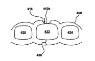
- FIGS. 4A-C illustrate the interactions of an activatable dental appliance on a tooth. Specifically, FIGS. 4A-C illustrate the movement of a tooth through the use of forces generated by activating a passive bump on the outer surface of the dental appliance in the course of orthodontic treatment.
- activatable dental appliance 400 includes passive bump 410 a .
- Dental appliance 400 generally conforms to teeth 420 , 422 and 424 of a patient's dentition. In an initial state, passive bump 410 a extends out from the buccal or outer surface of dental appliance 400 . It should be appreciated that passive bump 410 a is established prior to formation of activatable dental appliance 400 . Passive bump 410 a is activated by pressing bump 410 a into dental appliance 400 .
- dental appliance 400 includes space 430 for providing an unobstructed path for avoiding interferences in repositioning tooth 422 . As shown, space 430 is on the opposite or lingual side of tooth 422 as bump 410 a.
- active bump 410 b upon activation, extends into dental appliance 400 .
- active bump 410 b applies a force to tooth 422 , where the direction of force is indicated by arrow 415 .
- bump 410 b may be of such a shape to apply a specific force. For instance, a larger bump may provide a larger force on a tooth, depending on the location and orientation of the bump. The force as indicated by arrow 415 repositions tooth 422 , directing tooth 422 into space 430 .
- an alternative embodiment may include the bump 410 b having still another bump that would surround bump 410 b , so that when activated would further extend bump 410 b against the tooth 422 to create a new force at the same or near same location as bump 410 a.
- FIG. 4C illustrates dental appliance 400 where active bump 410 b has moved tooth 422 such that bump 410 b no longer applies any force to tooth 422 . Accordingly, space 430 has been reduced, as tooth 422 has moved into space 430 .
- FIG. 5 is a flow chart of a method 500 for repositioning teeth, in accordance with one embodiment of the present invention.
- the present embodiment provides an activatable dental appliance including activatable force applying regions.
- embodiments of the present invention are capable of providing multiple stage incremental repositioning of teeth.
- the present embodiment provides a polymeric shell dental appliance of a type that is removably placeable over a patient's dentition.
- the appliance includes a concave trough which conforms to a plurality of teeth when placed over the patient's dentition, and includes a geometry for repositioning the plurality of teeth from a first tooth arrangement to a second tooth arrangement.
- FIGS. 3A and 3B show an activatable dental appliance 210 .
- Active region 215 at least in part defines the geometry for repositioning tooth 230 .
- an activatable force applying region of the appliance is activated such that the appliance includes a second geometry for repositioning the plurality of teeth from the second tooth arrangement to a third tooth arrangement.
- passive region 220 at least in part defines the second geometry for further repositioning tooth 230 .
- an activation tool is used to activate the activatable force applying region.
- a finger is used to activate the activatable force applying region
- FIG. 6 is a flow chart of a method 600 for fabricating a dental appliance for repositioning at least one tooth, in accordance with one embodiment of the present invention.
- the present embodiment provides an activatable dental appliance including activatable force applying regions. As such, embodiments are capable of providing multiple stage incremental repositioning of teeth.
- a computer-generated model of a patient's teeth is created.
- a 3D computer model of jaw 100 of FIG. 1 is generated.
- a computer simulation is capable of modeling interactions among the teeth on jaw 100 .
- the 3D model can be used to simulate jaw movements including protrusive motions, lateral motions, and “tooth guided” motions where the path of lower jaw 100 is guided by teeth contacts rather than by anatomical limits of jaw 100 .
- Motions are applied to one jaw, but may also be applied to both the lower and upper jaws. Based on the computer-generated model, the final arrangement of the teeth in jaw 100 can be ascertained.
- a plurality of successive incremental tooth arrangements of the patient's teeth are determined, wherein an incremental tooth arrangement comprises repositioning at least one tooth.
- a plurality of INTDDSs are defined to correspond to incrementally adjusted dental appliances.
- the INTDDSs are defined using techniques for aligning teeth, which in general, mimic the way that teeth move when fixed orthodontic brackets and wires are used.
- predetermined INTDDSs are defined to provide a specific force along the most effective treatment path.
- FIG. 2A shows activatable digital appliance 210 based at least on a plurality of INTDDSs as described above. At least two sequential INTDDSs are digitally merged, where the first INTDDS is associated with forces generated by active region 215 and where the second INTDDS is associated with forces generated upon the activation of passive region 220 .
- the 3D model can be tested for digitally testing the forces exerted by active region 215 and passive region 220 upon activation. For example, forces exerted by active region 215 and passive region 220 upon activation are applied to the 3D model for testing the movement of the teeth to a new position.
- an indication for indicating a location on the appliance for activating the activatable force applying region is created. Thereafter, an appliance is fabricated.
- the appliance conforms to the patient's teeth and includes at least one activated force applying region for repositioning at least one tooth, includes at least one activatable force applying region for repositioning at least one tooth upon activation, and includes space for providing an unobstructed path for avoiding interferences in repositioning at least one tooth.
Abstract
Description
Claims (21)
Priority Applications (3)
| Application Number | Priority Date | Filing Date | Title |
|---|---|---|---|
| US11/999,984 US7914283B2 (en) | 2007-12-06 | 2007-12-06 | Activatable dental appliance |
| US12/963,447 US8469706B2 (en) | 2007-12-06 | 2010-12-08 | Activatable dental appliance |
| US12/963,419 US8348665B2 (en) | 2007-12-06 | 2010-12-08 | Activatable dental appliance |
Applications Claiming Priority (1)
| Application Number | Priority Date | Filing Date | Title |
|---|---|---|---|
| US11/999,984 US7914283B2 (en) | 2007-12-06 | 2007-12-06 | Activatable dental appliance |
Related Child Applications (2)
| Application Number | Title | Priority Date | Filing Date |
|---|---|---|---|
| US12/963,419 Division US8348665B2 (en) | 2007-12-06 | 2010-12-08 | Activatable dental appliance |
| US12/963,447 Division US8469706B2 (en) | 2007-12-06 | 2010-12-08 | Activatable dental appliance |
Publications (2)
| Publication Number | Publication Date |
|---|---|
| US20090148803A1 US20090148803A1 (en) | 2009-06-11 |
| US7914283B2 true US7914283B2 (en) | 2011-03-29 |
Family
ID=40722026
Family Applications (3)
| Application Number | Title | Priority Date | Filing Date |
|---|---|---|---|
| US11/999,984 Active 2028-04-24 US7914283B2 (en) | 2007-12-06 | 2007-12-06 | Activatable dental appliance |
| US12/963,419 Active US8348665B2 (en) | 2007-12-06 | 2010-12-08 | Activatable dental appliance |
| US12/963,447 Active 2028-03-08 US8469706B2 (en) | 2007-12-06 | 2010-12-08 | Activatable dental appliance |
Family Applications After (2)
| Application Number | Title | Priority Date | Filing Date |
|---|---|---|---|
| US12/963,419 Active US8348665B2 (en) | 2007-12-06 | 2010-12-08 | Activatable dental appliance |
| US12/963,447 Active 2028-03-08 US8469706B2 (en) | 2007-12-06 | 2010-12-08 | Activatable dental appliance |
Country Status (1)
| Country | Link |
|---|---|
| US (3) | US7914283B2 (en) |
Cited By (43)
| Publication number | Priority date | Publication date | Assignee | Title |
|---|---|---|---|---|
| US8348665B2 (en) | 2007-12-06 | 2013-01-08 | Align Technology, Inc. | Activatable dental appliance |
| US20150305830A1 (en) * | 2001-04-13 | 2015-10-29 | Orametrix, Inc. | Tooth positioning appliance and uses thereof |
| US10335250B2 (en) | 2015-10-07 | 2019-07-02 | uLab Systems, Inc. | Three-dimensional printed dental appliances using lattices |
| US10357342B2 (en) | 2016-09-21 | 2019-07-23 | uLab Systems, Inc. | Digital dental examination and documentation |
| US10357336B2 (en) | 2015-10-07 | 2019-07-23 | uLab Systems, Inc. | Systems and methods for fabricating dental appliances or shells |
| US10548690B2 (en) | 2015-10-07 | 2020-02-04 | uLab Systems, Inc. | Orthodontic planning systems |
| US10624717B2 (en) | 2015-10-07 | 2020-04-21 | Ulab Systems Inc. | Tooth modeling system |
| US10631953B2 (en) | 2015-10-07 | 2020-04-28 | uLab Systems, Inc. | Three-dimensional printed dental appliances using support structures |
| US10952821B2 (en) | 2016-09-21 | 2021-03-23 | uLab Systems, Inc. | Combined orthodontic movement of teeth with temporomandibular joint therapy |
| US11109946B2 (en) | 2019-09-16 | 2021-09-07 | Align Technology, Inc. | Durable ornamental indicia carrier |
| US11194312B2 (en) | 2017-03-31 | 2021-12-07 | Align Technology, Inc. | Orthodontic appliances including at least partially un-erupted teeth and method of forming them |
| US11304778B2 (en) | 2016-06-17 | 2022-04-19 | Align Technology, Inc. | Intraoral appliances with proximity and contact sensing |
| US11364098B2 (en) | 2016-09-21 | 2022-06-21 | uLab Systems, Inc. | Combined orthodontic movement of teeth with airway development therapy |
| US11432908B2 (en) | 2017-12-15 | 2022-09-06 | Align Technology, Inc. | Closed loop adaptive orthodontic treatment methods and apparatuses |
| US20220313391A1 (en) * | 2021-03-31 | 2022-10-06 | Larry J. Moray | Methods and apparatuses for orthodontic aligners with pressure areas |
| US11471250B2 (en) | 2010-04-30 | 2022-10-18 | Align Technology, Inc. | Reinforced aligner hooks |
| US11504214B2 (en) | 2018-05-11 | 2022-11-22 | Align Technology, Inc. | Devices, systems, and computer-implemented methods for dental attachment templates |
| US11576754B2 (en) | 2016-12-02 | 2023-02-14 | Align Technology, Inc. | Methods and apparatuses for customizing a rapid palatal expander |
| US11576766B2 (en) | 2017-06-26 | 2023-02-14 | Align Technology, Inc. | Biosensor performance indicator for intraoral appliances |
| US11583365B2 (en) | 2015-10-07 | 2023-02-21 | uLab Systems, Inc. | System and methods for tooth movement as a flock |
| US11602414B2 (en) | 2019-06-11 | 2023-03-14 | Align Technology, Inc. | Aligner material, cleanliness, and quality detection via aligner case |
| US11612455B2 (en) | 2016-06-17 | 2023-03-28 | Align Technology, Inc. | Orthodontic appliance performance monitor |
| US11648090B2 (en) | 2012-05-14 | 2023-05-16 | Align Technology, Inc. | Multilayer polymer sheets |
| US11661468B2 (en) | 2020-08-27 | 2023-05-30 | Align Technology, Inc. | Additive manufacturing using variable temperature-controlled resins |
| US11701203B2 (en) | 2018-06-29 | 2023-07-18 | Align Technology, Inc. | Dental appliance hook placement and visualization |
| US11718019B2 (en) | 2018-09-14 | 2023-08-08 | Align Technology, Inc. | System for hybrid 3D printing with photo-curable materials |
| US11723748B2 (en) | 2019-12-23 | 2023-08-15 | Align Technology, Inc. | 2D-to-3D tooth reconstruction, optimization, and positioning frameworks using a differentiable renderer |
| US11744678B2 (en) | 2014-08-22 | 2023-09-05 | Align Technology, Inc. | Attachment structure |
| US11752030B2 (en) | 2015-01-13 | 2023-09-12 | Align Technology, Inc. | Systems and methods for positioning a patient's mandible in response to sleep apnea status |
| US11751978B2 (en) | 2014-06-20 | 2023-09-12 | Align Technology, Inc. | Layered aligners with discontinuities |
| US11771527B2 (en) | 2019-02-20 | 2023-10-03 | Sdc U.S. Smilepay Spv | Limited wear aligner and treatment methods |
| US11771531B2 (en) | 2015-01-13 | 2023-10-03 | Align Technology, Inc. | Mandibular advancement and retraction via bone anchoring devices |
| US11786341B2 (en) | 2019-12-09 | 2023-10-17 | Align Technology, Inc. | Occlusal block design for lateral locking |
| US11793667B2 (en) | 2015-01-13 | 2023-10-24 | Align Technology, Inc. | Systems, methods, and devices for applying distributed forces for mandibular advancement |
| US11793608B2 (en) | 2017-11-01 | 2023-10-24 | Align Technology, Inc. | Systems and methods for correcting malocclusions of teeth |
| US11806208B2 (en) | 2014-03-21 | 2023-11-07 | Align Technology, Inc. | Orthodontic appliances with shell segments and elastic segments |
| US11826221B2 (en) | 2017-06-09 | 2023-11-28 | Align Technology, Inc. | Systems and methods including palatal expanders with anchor-receiving features |
| US11845868B2 (en) | 2020-03-13 | 2023-12-19 | Align Technology, Inc. | Weak covalent crosslinks in thermoset materials for increased toughness |
| US11851510B2 (en) | 2020-03-02 | 2023-12-26 | Align Technology, Inc. | Low viscosity photo-curable resins for the direct fabrication of orthodontic appliances |
| US11883256B2 (en) | 2017-10-05 | 2024-01-30 | Align Technology, Inc. | Methods of forming interproximal reduction templates |
| US11939287B2 (en) | 2021-06-24 | 2024-03-26 | Align Technology, Inc. | Recovery of monomeric and oligomeric building blocks from polymeric materials |
| US11944514B2 (en) | 2015-07-07 | 2024-04-02 | Align Technology, Inc. | Methods for fabricating dental appliances with integrally formed components |
| US11950976B2 (en) | 2022-07-11 | 2024-04-09 | Align Technology, Inc. | Dental appliance etch template |
Families Citing this family (22)
| Publication number | Priority date | Publication date | Assignee | Title |
|---|---|---|---|---|
| FR2947443B1 (en) * | 2009-07-03 | 2021-06-04 | Daniel Julie | DESIGN OF A UNIQUE AND REACTIVABLE ORTHODONTIC GUTTER |
| US9333053B2 (en) | 2013-08-07 | 2016-05-10 | Bandar ALYAMI | Orthodontic device |
| US20150132707A1 (en) * | 2013-09-11 | 2015-05-14 | Ormco Corporation | Braces to aligner transition in orthodontic treatment |
| US11103328B2 (en) * | 2014-12-30 | 2021-08-31 | 3M Innovative Properties Company | Dental appliance providing exposed occlusal surfaces |
| US10179035B2 (en) * | 2015-03-04 | 2019-01-15 | Real 3D Polymers Group Llc | Direct 3D-printed orthodontic aligners with torque, rotation, and full control anchors |
| US11484390B2 (en) * | 2015-03-04 | 2022-11-01 | Real 3D Polymers Llc | Direct 3D-printed orthodontic aligners with torque, rotation, and full control anchors |
| US10874483B2 (en) | 2015-07-07 | 2020-12-29 | Align Technology, Inc. | Direct fabrication of attachment templates with adhesive |
| US10743964B2 (en) | 2015-07-07 | 2020-08-18 | Align Technology, Inc. | Dual aligner assembly |
| EP3691562B1 (en) | 2017-10-06 | 2023-10-25 | 3M Innovative Properties Company | Orthodontic palatal expander including split beams |
| US11395718B2 (en) | 2017-10-06 | 2022-07-26 | 3M Innovative Properties Company | Removable dental appliance including jumpers |
| WO2019069165A1 (en) * | 2017-10-06 | 2019-04-11 | 3M Innovative Properties Company | Removable dental appliance including positioning member |
| WO2019069166A1 (en) | 2017-10-06 | 2019-04-11 | 3M Innovative Properties Company | Removable dental appliance including spring member |
| EP3691560B8 (en) | 2017-10-06 | 2024-04-03 | Solventum Intellectual Properties Company | Removable dental appliance including spring bellows |
| US10792128B2 (en) | 2017-11-30 | 2020-10-06 | Richter Orthodontics, P.C. | Orthodontic settling retainer |
| US10779917B2 (en) * | 2018-02-20 | 2020-09-22 | Ivoclar Vivadent Ag | Computer implemented method for modifying a digital three-dimensional model of a dentition |
| US10315353B1 (en) | 2018-11-13 | 2019-06-11 | SmileDirectClub LLC | Systems and methods for thermoforming dental aligners |
| JP2021534933A (en) | 2018-11-15 | 2021-12-16 | スリーエム イノベイティブ プロパティズ カンパニー | Detachable dental device with gingival ridge |
| JP2022507499A (en) | 2018-11-15 | 2022-01-18 | スリーエム イノベイティブ プロパティズ カンパニー | Detachable dental device with adjacent interdental reinforcement |
| US11007042B2 (en) | 2019-02-06 | 2021-05-18 | Sdc U.S. Smilepay Spv | Systems and methods for marking models for dental aligner fabrication |
| US10482192B1 (en) | 2019-02-12 | 2019-11-19 | SmileDirectClub LLC | Systems and methods for selecting and marking a location on a dental aligner |
| RU2733161C1 (en) * | 2020-02-28 | 2020-09-29 | Сергей Дарчоевич Арутюнов | Method of making a removable denture |
| CN111839763B (en) * | 2020-07-30 | 2022-02-11 | 正雅齿科科技(上海)有限公司 | Design method, manufacturing method and system of digital shell-shaped tooth appliance |
Citations (5)
| Publication number | Priority date | Publication date | Assignee | Title |
|---|---|---|---|---|
| US6814574B2 (en) | 2002-11-06 | 2004-11-09 | Align Technology, Inc. | Dental pliers for forming and removing bumps on appliances |
| US20050048433A1 (en) * | 2003-08-29 | 2005-03-03 | Hilliard Jack Keith | Automated method for producing improved orthodontic aligners |
| US20060188834A1 (en) * | 2005-02-18 | 2006-08-24 | Hilliard Jack K | Method for creating features in orthodontic aligners |
| US7374421B2 (en) * | 2005-03-31 | 2008-05-20 | Frederick Solomon | System and method for improved control of tooth movement with elastic repositioning appliances |
| US20080254402A1 (en) * | 2006-10-16 | 2008-10-16 | Jack Keith Hilliard | System for producing orthodontic aligners by cnc machining |
Family Cites Families (144)
| Publication number | Priority date | Publication date | Assignee | Title |
|---|---|---|---|---|
| US2467432A (en) | 1943-07-23 | 1949-04-19 | Harold D Kesling | Method of making orthodontic appliances and of positioning teeth |
| US3407500A (en) | 1966-05-06 | 1968-10-29 | Peter C. Kesling | Tooth positioner |
| US3660900A (en) | 1969-11-10 | 1972-05-09 | Lawrence F Andrews | Method and apparatus for improved orthodontic bracket and arch wire technique |
| US3600808A (en) | 1970-01-22 | 1971-08-24 | James Jackson Reeve | Anterior root-torquing auxiliary wire |
| US3860803A (en) | 1970-08-24 | 1975-01-14 | Diecomp Inc | Automatic method and apparatus for fabricating progressive dies |
| US3683502A (en) | 1970-09-14 | 1972-08-15 | Melvin Wallshein | Orthodontic systems |
| US3738005A (en) | 1972-03-22 | 1973-06-12 | M Cohen | Method and apparatus for applying orthodontic brackets and the like |
| US3916526A (en) | 1973-05-10 | 1975-11-04 | Fred Frank Schudy | Method and apparatus for orthodontic treatment |
| US3922786A (en) | 1974-01-30 | 1975-12-02 | Joseph L Lavin | Method and apparatus for forming and fitting orthodontic appliances |
| US3983628A (en) | 1975-01-24 | 1976-10-05 | Raul Acevedo | Dental articulator, new bite registration guide, and diagnostic procedure associated with stereodont orthodontic study model |
| US3950851A (en) | 1975-03-05 | 1976-04-20 | Bergersen Earl Olaf | Orthodontic positioner and method for improving retention of tooth alignment therewith |
| US4014096A (en) | 1975-03-25 | 1977-03-29 | Dellinger Eugene L | Method and apparatus for orthodontic treatment |
| JPS5358191A (en) | 1976-11-05 | 1978-05-25 | Osamu Yoshii | Method of producing dental correction treating instrument using silicon resin material |
| US4348178A (en) | 1977-01-03 | 1982-09-07 | Kurz Craven H | Vibrational orthodontic appliance |
| US4195046A (en) | 1978-05-04 | 1980-03-25 | Kesling Peter C | Method for molding air holes into a tooth positioning and retaining appliance |
| US4324547A (en) | 1978-09-16 | 1982-04-13 | Vishay Intertechnology, Inc. | Dentistry technique |
| US4253828A (en) | 1979-04-09 | 1981-03-03 | Coles Donna C | Orthodontic appliance |
| DE2936847A1 (en) | 1979-09-12 | 1981-03-19 | Paul Dr. 6054 Rodgau Heitlinger | METHOD FOR PRODUCING DENTAL SPARE AND DEVICE FOR IMPLEMENTING THE METHOD |
| US4575805A (en) | 1980-12-24 | 1986-03-11 | Moermann Werner H | Method and apparatus for the fabrication of custom-shaped implants |
| DE3203937C2 (en) | 1982-02-05 | 1985-10-03 | Luc Dr. 4150 Krefeld Barrut | Method and device for machine restoration or correction of at least one tooth or for machine preparation of at least one tooth for a fixed prosthetic restoration and for machine production of the fixed prosthetic restoration |
| FR2525103B1 (en) | 1982-04-14 | 1985-09-27 | Duret Francois | IMPRESSION TAKING DEVICE BY OPTICAL MEANS, PARTICULARLY FOR THE AUTOMATIC PRODUCTION OF PROSTHESES |
| US4663720A (en) | 1984-02-21 | 1987-05-05 | Francois Duret | Method of and apparatus for making a prosthesis, especially a dental prosthesis |
| US4500294A (en) | 1983-10-03 | 1985-02-19 | Epic International Corporation | Method and device for detecting dental cavities |
| US4526540A (en) | 1983-12-19 | 1985-07-02 | Dellinger Eugene L | Orthodontic apparatus and method for treating malocclusion |
| DE3415006A1 (en) | 1984-04-19 | 1985-11-07 | Helge Dr. 8000 München Fischer-Brandies | DENTAL PROCESS AND DEVICE FOR BENDING AND TURNING A WIRE PIECE |
| US4798534A (en) | 1984-08-03 | 1989-01-17 | Great Lakes Orthodontic Laboratories Inc. | Method of making a dental appliance |
| US4575330A (en) | 1984-08-08 | 1986-03-11 | Uvp, Inc. | Apparatus for production of three-dimensional objects by stereolithography |
| US4609349A (en) | 1984-09-24 | 1986-09-02 | Cain Steve B | Active removable orthodontic appliance and method of straightening teeth |
| US4591341A (en) | 1984-10-03 | 1986-05-27 | Andrews Lawrence F | Orthodontic positioner and method of manufacturing same |
| US4664626A (en) | 1985-03-19 | 1987-05-12 | Kesling Peter C | System for automatically preventing overtipping and/or overuprighting in the begg technique |
| US4763791A (en) | 1985-06-06 | 1988-08-16 | Excel Dental Studios, Inc. | Dental impression supply kit |
| GB2176402B (en) | 1985-06-20 | 1989-04-19 | Craig Med Prod Ltd | Wound management appliance for use on the human skin |
| US4936862A (en) | 1986-05-30 | 1990-06-26 | Walker Peter S | Method of designing and manufacturing a human joint prosthesis |
| CH672722A5 (en) | 1986-06-24 | 1989-12-29 | Marco Brandestini | |
| US4877398A (en) | 1987-04-16 | 1989-10-31 | Tp Orthodontics, Inc. | Bracket for permitting tipping and limiting uprighting |
| CA1284040C (en) | 1986-06-26 | 1991-05-14 | Peter C. Kesling | Edgewise bracket to provide both free crown tipping and a predetermineddegree of root uprighting |
| US4676747A (en) | 1986-08-06 | 1987-06-30 | Tp Orthodontics, Inc. | Torquing auxiliary |
| US4983334A (en) | 1986-08-28 | 1991-01-08 | Loren S. Adell | Method of making an orthodontic appliance |
| US4755139A (en) | 1987-01-29 | 1988-07-05 | Great Lakes Orthodontics, Ltd. | Orthodontic anchor appliance and method for teeth positioning and method of constructing the appliance |
| US4850864A (en) | 1987-03-30 | 1989-07-25 | Diamond Michael K | Bracket placing instrument |
| US4850865A (en) | 1987-04-30 | 1989-07-25 | Napolitano John R | Orthodontic method and apparatus |
| US4856991A (en) | 1987-05-05 | 1989-08-15 | Great Lakes Orthodontics, Ltd. | Orthodontic finishing positioner and method of construction |
| US5186623A (en) | 1987-05-05 | 1993-02-16 | Great Lakes Orthodontics, Ltd. | Orthodontic finishing positioner and method of construction |
| US4836778A (en) | 1987-05-26 | 1989-06-06 | Vexcel Corporation | Mandibular motion monitoring system |
| DE3723555C2 (en) | 1987-07-16 | 1994-08-11 | Steinbichler Hans | Process for the production of dentures |
| NL8702391A (en) | 1987-10-07 | 1989-05-01 | Elephant Edelmetaal Bv | METHOD FOR MANUFACTURING A DENTAL CROWN FOR A TEETH PREPARATION USING A CAD-CAM SYSTEM |
| US4793803A (en) | 1987-10-08 | 1988-12-27 | Martz Martin G | Removable tooth positioning appliance and method |
| US4880380A (en) | 1987-10-13 | 1989-11-14 | Martz Martin G | Orthodonture appliance which may be manually installed and removed by the patient |
| US5130064A (en) | 1988-04-18 | 1992-07-14 | 3D Systems, Inc. | Method of making a three dimensional object by stereolithography |
| US4941826A (en) | 1988-06-09 | 1990-07-17 | William Loran | Apparatus for indirect dental machining |
| US5100316A (en) | 1988-09-26 | 1992-03-31 | Wildman Alexander J | Orthodontic archwire shaping method |
| US5055039A (en) | 1988-10-06 | 1991-10-08 | Great Lakes Orthodontics, Ltd. | Orthodontic positioner and methods of making and using same |
| US4935635A (en) | 1988-12-09 | 1990-06-19 | Harra Dale G O | System for measuring objects in three dimensions |
| IL88842A (en) | 1988-12-30 | 1990-07-26 | Shafir Aaron | Apparatus and method for digitizing the contour of a surface particularly useful for preparing a dental crown |
| AU4950290A (en) | 1989-01-24 | 1990-08-24 | Dolphin Imaging Systems Inc. | Method and apparatus for generating cephalometric images |
| US5011405A (en) | 1989-01-24 | 1991-04-30 | Dolphin Imaging Systems | Method for determining orthodontic bracket placement |
| US4889238A (en) | 1989-04-03 | 1989-12-26 | The Procter & Gamble Company | Medicament package for increasing compliance with complex therapeutic regimens |
| US4975052A (en) | 1989-04-18 | 1990-12-04 | William Spencer | Orthodontic appliance for reducing tooth rotation |
| US5128870A (en) | 1989-06-09 | 1992-07-07 | Regents Of The University Of Minnesota | Automated high-precision fabrication of objects of complex and unique geometry |
| US5121333A (en) | 1989-06-09 | 1992-06-09 | Regents Of The University Of Minnesota | Method and apparatus for manipulating computer-based representations of objects of complex and unique geometry |
| US5027281A (en) | 1989-06-09 | 1991-06-25 | Regents Of The University Of Minnesota | Method and apparatus for scanning and recording of coordinates describing three dimensional objects of complex and unique geometry |
| US5184306A (en) | 1989-06-09 | 1993-02-02 | Regents Of The University Of Minnesota | Automated high-precision fabrication of objects of complex and unique geometry |
| US5257203A (en) | 1989-06-09 | 1993-10-26 | Regents Of The University Of Minnesota | Method and apparatus for manipulating computer-based representations of objects of complex and unique geometry |
| JPH039712U (en) | 1989-06-20 | 1991-01-30 | ||
| FR2652256A1 (en) | 1989-09-26 | 1991-03-29 | Jourda Gerard | DEVICE FOR ESTABLISHING THE TRACE OF A REMOVABLE PARTIAL DENTAL PLATE. |
| US5474448A (en) | 1990-01-19 | 1995-12-12 | Ormco Corporation | Low profile orthodontic appliance |
| US5431562A (en) | 1990-01-19 | 1995-07-11 | Ormco Corporation | Method and apparatus for designing and forming a custom orthodontic appliance and for the straightening of teeth therewith |
| US5454717A (en) | 1990-01-19 | 1995-10-03 | Ormco Corporation | Custom orthodontic brackets and bracket forming method and apparatus |
| US5395238A (en) | 1990-01-19 | 1995-03-07 | Ormco Corporation | Method of forming orthodontic brace |
| US5368478A (en) | 1990-01-19 | 1994-11-29 | Ormco Corporation | Method for forming jigs for custom placement of orthodontic appliances on teeth |
| US5139419A (en) | 1990-01-19 | 1992-08-18 | Ormco Corporation | Method of forming an orthodontic brace |
| US5447432A (en) | 1990-01-19 | 1995-09-05 | Ormco Corporation | Custom orthodontic archwire forming method and apparatus |
| US5533895A (en) | 1990-01-19 | 1996-07-09 | Ormco Corporation | Orthodontic appliance and group standardized brackets therefor and methods of making, assembling and using appliance to straighten teeth |
| US5440326A (en) | 1990-03-21 | 1995-08-08 | Gyration, Inc. | Gyroscopic pointer |
| US5562448A (en) | 1990-04-10 | 1996-10-08 | Mushabac; David R. | Method for facilitating dental diagnosis and treatment |
| US5452219A (en) | 1990-06-11 | 1995-09-19 | Dentsply Research & Development Corp. | Method of making a tooth mold |
| US5340309A (en) | 1990-09-06 | 1994-08-23 | Robertson James G | Apparatus and method for recording jaw motion |
| SE468198B (en) | 1990-12-12 | 1992-11-23 | Nobelpharma Ab | PROCEDURE AND DEVICE FOR MANUFACTURE OF INDIVIDUALLY DESIGNED THREE-DIMENSIONAL BODIES USEFUL AS TENDERS, PROTESTES, ETC |
| US5131844A (en) | 1991-04-08 | 1992-07-21 | Foster-Miller, Inc. | Contact digitizer, particularly for dental applications |
| US5131843A (en) | 1991-05-06 | 1992-07-21 | Ormco Corporation | Orthodontic archwire |
| US5145364A (en) | 1991-05-15 | 1992-09-08 | M-B Orthodontics, Inc. | Removable orthodontic appliance |
| US5176517A (en) | 1991-10-24 | 1993-01-05 | Tru-Tain, Inc. | Dental undercut application device and method of use |
| SE469158B (en) | 1991-11-01 | 1993-05-24 | Nobelpharma Ab | DENTAL SENSOR DEVICE INTENDED TO BE USED IN CONNECTION WITH CONTROL OF A WORKING EQUIPMENT |
| US5328362A (en) | 1992-03-11 | 1994-07-12 | Watson Sherman L | Soft resilient interocclusal dental appliance, method of forming same and composition for same |
| US5273429A (en) | 1992-04-03 | 1993-12-28 | Foster-Miller, Inc. | Method and apparatus for modeling a dental prosthesis |
| US5384862A (en) | 1992-05-29 | 1995-01-24 | Cimpiter Corporation | Radiographic image evaluation apparatus and method |
| FR2693096B1 (en) | 1992-07-06 | 1994-09-23 | Deshayes Marie Josephe | Process for modeling the cranial and facial morphology from an x-ray of the skull. |
| WO1994010935A1 (en) | 1992-11-09 | 1994-05-26 | Ormco Corporation | Custom orthodontic appliance forming method and apparatus |
| US5542842A (en) | 1992-11-09 | 1996-08-06 | Ormco Corporation | Bracket placement jig assembly and method of placing orthodontic brackets on teeth therewith |
| US5456600A (en) | 1992-11-09 | 1995-10-10 | Ormco Corporation | Coordinated orthodontic archwires and method of making same |
| US5528735A (en) | 1993-03-23 | 1996-06-18 | Silicon Graphics Inc. | Method and apparatus for displaying data within a three-dimensional information landscape |
| SE501333C2 (en) | 1993-05-27 | 1995-01-16 | Sandvik Ab | Method for making ceramic tooth restorations |
| CN1054737C (en) | 1993-07-12 | 2000-07-26 | 欧索-泰公司 | A multi-racial preformed orthodontic treatment appliance |
| SE501411C2 (en) | 1993-07-12 | 1995-02-06 | Nobelpharma Ab | Method and apparatus for three-dimensional body useful in the human body |
| SE501410C2 (en) | 1993-07-12 | 1995-02-06 | Nobelpharma Ab | Method and apparatus in connection with the manufacture of tooth, bridge, etc. |
| NL9301308A (en) | 1993-07-26 | 1995-02-16 | Willem Frederick Van Nifterick | Method of securing a dental prosthesis to implants in a patient's jawbone and using means thereof. |
| US5382164A (en) | 1993-07-27 | 1995-01-17 | Stern; Sylvan S. | Method for making dental restorations and the dental restoration made thereby |
| US5435902A (en) | 1993-10-01 | 1995-07-25 | Andre, Sr.; Larry E. | Method of incremental object fabrication |
| US5338198A (en) | 1993-11-22 | 1994-08-16 | Dacim Laboratory Inc. | Dental modeling simulator |
| SE502427C2 (en) | 1994-02-18 | 1995-10-16 | Nobelpharma Ab | Method and device utilizing articulator and computer equipment |
| US5880961A (en) | 1994-08-02 | 1999-03-09 | Crump; Craig D. | Appararus and method for creating three-dimensional modeling data from an object |
| US5621648A (en) | 1994-08-02 | 1997-04-15 | Crump; Craig D. | Apparatus and method for creating three-dimensional modeling data from an object |
| SE503498C2 (en) | 1994-10-04 | 1996-06-24 | Nobelpharma Ab | Method and device for a product intended to be part of the human body and a scanning device for a model for the product |
| US5549476A (en) | 1995-03-27 | 1996-08-27 | Stern; Sylvan S. | Method for making dental restorations and the dental restoration made thereby |
| JP3672966B2 (en) | 1995-04-14 | 2005-07-20 | 株式会社ユニスン | Method and apparatus for creating dental prediction model |
| US5645421A (en) | 1995-04-28 | 1997-07-08 | Great Lakes Orthodontics Ltd. | Orthodontic appliance debonder |
| US5655653A (en) | 1995-07-11 | 1997-08-12 | Minnesota Mining And Manufacturing Company | Pouch for orthodontic appliance |
| WO1997003622A1 (en) | 1995-07-21 | 1997-02-06 | Cadent Ltd. | Method and system for acquiring three-dimensional teeth image |
| US5742700A (en) | 1995-08-10 | 1998-04-21 | Logicon, Inc. | Quantitative dental caries detection system and method |
| US5725376A (en) | 1996-02-27 | 1998-03-10 | Poirier; Michel | Methods for manufacturing a dental implant drill guide and a dental implant superstructure |
| US6382975B1 (en) | 1997-02-26 | 2002-05-07 | Technique D'usinage Sinlab Inc. | Manufacturing a dental implant drill guide and a dental implant superstructure |
| US5692894A (en) | 1996-04-08 | 1997-12-02 | Raintree Essix, Inc. | Thermoformed plastic dental retainer and method of construction |
| US5799100A (en) | 1996-06-03 | 1998-08-25 | University Of South Florida | Computer-assisted method and apparatus for analysis of x-ray images using wavelet transforms |
| US5823778A (en) | 1996-06-14 | 1998-10-20 | The United States Of America As Represented By The Secretary Of The Air Force | Imaging method for fabricating dental devices |
| US5725378A (en) | 1996-08-16 | 1998-03-10 | Wang; Hong-Chi | Artificial tooth assembly |
| JPH1075963A (en) | 1996-09-06 | 1998-03-24 | Nikon Corp | Method for designing dental prosthetic appliance model and medium recording program for executing the method |
| AUPO280996A0 (en) | 1996-10-04 | 1996-10-31 | Dentech Investments Pty Ltd | Creation and utilization of 3D teeth models |
| JP2824424B2 (en) | 1996-11-07 | 1998-11-11 | 株式会社エフ・エーラボ | 3D machining method |
| US6217334B1 (en) | 1997-01-28 | 2001-04-17 | Iris Development Corporation | Dental scanning method and apparatus |
| US5957686A (en) | 1997-04-29 | 1999-09-28 | Anthony; Wayne L. | Incisor block |
| US5848115A (en) | 1997-05-02 | 1998-12-08 | General Electric Company | Computed tomography metrology |
| US5879158A (en) | 1997-05-20 | 1999-03-09 | Doyle; Walter A. | Orthodontic bracketing system and method therefor |
| US5866058A (en) | 1997-05-29 | 1999-02-02 | Stratasys Inc. | Method for rapid prototyping of solid models |
| US6705863B2 (en) | 1997-06-20 | 2004-03-16 | Align Technology, Inc. | Attachment devices and methods for a dental appliance |
| AU744385B2 (en) | 1997-06-20 | 2002-02-21 | Align Technology, Inc. | Method and system for incrementally moving teeth |
| US6309215B1 (en) | 1997-06-20 | 2001-10-30 | Align Technology Inc. | Attachment devices and method for a dental applicance |
| US6183248B1 (en) | 1998-11-30 | 2001-02-06 | Muhammad Chishti | System and method for releasing tooth positioning appliances |
| US5975893A (en) | 1997-06-20 | 1999-11-02 | Align Technology, Inc. | Method and system for incrementally moving teeth |
| US6152731A (en) | 1997-09-22 | 2000-11-28 | 3M Innovative Properties Company | Methods for use in dental articulation |
| US5934288A (en) | 1998-04-23 | 1999-08-10 | General Electric Company | Method and apparatus for displaying 3D ultrasound data using three modes of operation |
| US5971754A (en) | 1998-07-30 | 1999-10-26 | Sondhi; Anoop | Indirect bonding method and adhesive for orthodontic treatment |
| US5964587A (en) | 1998-09-16 | 1999-10-12 | Sato; Mikio | Bite control point and a method to form a projection on tooth surface |
| US6572372B1 (en) | 2000-04-25 | 2003-06-03 | Align Technology, Inc. | Embedded features and methods of a dental appliance |
| US6123544A (en) | 1998-12-18 | 2000-09-26 | 3M Innovative Properties Company | Method and apparatus for precise bond placement of orthodontic appliances |
| US6190165B1 (en) | 1999-03-23 | 2001-02-20 | Ormco Corporation | Plastic orthodontic appliance having mechanical bonding base and method of making same |
| US6350120B1 (en) | 1999-11-30 | 2002-02-26 | Orametrix, Inc. | Method and apparatus for designing an orthodontic apparatus to provide tooth movement |
| US6315553B1 (en) | 1999-11-30 | 2001-11-13 | Orametrix, Inc. | Method and apparatus for site treatment of an orthodontic patient |
| US6633789B1 (en) | 2000-02-17 | 2003-10-14 | Align Technology, Inc. | Effiicient data representation of teeth model |
| US6463344B1 (en) | 2000-02-17 | 2002-10-08 | Align Technology, Inc. | Efficient data representation of teeth model |
| US6524101B1 (en) | 2000-04-25 | 2003-02-25 | Align Technology, Inc. | System and methods for varying elastic modulus appliances |
| US6402707B1 (en) | 2000-06-28 | 2002-06-11 | Denupp Corporation Bvi | Method and system for real time intra-orally acquiring and registering three-dimensional measurements and images of intra-oral objects and features |
| US6482298B1 (en) | 2000-09-27 | 2002-11-19 | International Business Machines Corporation | Apparatus for electroplating alloy films |
| US7104790B2 (en) | 2002-05-31 | 2006-09-12 | Cronauer Edward A | Orthodontic appliance with embedded wire for moving teeth and method |
| US7914283B2 (en) | 2007-12-06 | 2011-03-29 | Align Technology, Inc. | Activatable dental appliance |
-
2007
- 2007-12-06 US US11/999,984 patent/US7914283B2/en active Active
-
2010
- 2010-12-08 US US12/963,419 patent/US8348665B2/en active Active
- 2010-12-08 US US12/963,447 patent/US8469706B2/en active Active
Patent Citations (5)
| Publication number | Priority date | Publication date | Assignee | Title |
|---|---|---|---|---|
| US6814574B2 (en) | 2002-11-06 | 2004-11-09 | Align Technology, Inc. | Dental pliers for forming and removing bumps on appliances |
| US20050048433A1 (en) * | 2003-08-29 | 2005-03-03 | Hilliard Jack Keith | Automated method for producing improved orthodontic aligners |
| US20060188834A1 (en) * | 2005-02-18 | 2006-08-24 | Hilliard Jack K | Method for creating features in orthodontic aligners |
| US7374421B2 (en) * | 2005-03-31 | 2008-05-20 | Frederick Solomon | System and method for improved control of tooth movement with elastic repositioning appliances |
| US20080254402A1 (en) * | 2006-10-16 | 2008-10-16 | Jack Keith Hilliard | System for producing orthodontic aligners by cnc machining |
Cited By (56)
| Publication number | Priority date | Publication date | Assignee | Title |
|---|---|---|---|---|
| US20150305830A1 (en) * | 2001-04-13 | 2015-10-29 | Orametrix, Inc. | Tooth positioning appliance and uses thereof |
| US8469706B2 (en) | 2007-12-06 | 2013-06-25 | Align Technology, Inc. | Activatable dental appliance |
| US8348665B2 (en) | 2007-12-06 | 2013-01-08 | Align Technology, Inc. | Activatable dental appliance |
| US11471250B2 (en) | 2010-04-30 | 2022-10-18 | Align Technology, Inc. | Reinforced aligner hooks |
| US11648090B2 (en) | 2012-05-14 | 2023-05-16 | Align Technology, Inc. | Multilayer polymer sheets |
| US11806208B2 (en) | 2014-03-21 | 2023-11-07 | Align Technology, Inc. | Orthodontic appliances with shell segments and elastic segments |
| US11751978B2 (en) | 2014-06-20 | 2023-09-12 | Align Technology, Inc. | Layered aligners with discontinuities |
| US11744678B2 (en) | 2014-08-22 | 2023-09-05 | Align Technology, Inc. | Attachment structure |
| US11793667B2 (en) | 2015-01-13 | 2023-10-24 | Align Technology, Inc. | Systems, methods, and devices for applying distributed forces for mandibular advancement |
| US11771531B2 (en) | 2015-01-13 | 2023-10-03 | Align Technology, Inc. | Mandibular advancement and retraction via bone anchoring devices |
| US11752030B2 (en) | 2015-01-13 | 2023-09-12 | Align Technology, Inc. | Systems and methods for positioning a patient's mandible in response to sleep apnea status |
| US11944514B2 (en) | 2015-07-07 | 2024-04-02 | Align Technology, Inc. | Methods for fabricating dental appliances with integrally formed components |
| US11771524B2 (en) | 2015-10-07 | 2023-10-03 | uLab Systems, Inc. | Three-dimensional printed dental appliances using support structures |
| US11051913B2 (en) | 2015-10-07 | 2021-07-06 | Ulab Systems Inc. | Methods for fabricating dental appliances or shells |
| US11583365B2 (en) | 2015-10-07 | 2023-02-21 | uLab Systems, Inc. | System and methods for tooth movement as a flock |
| US10631953B2 (en) | 2015-10-07 | 2020-04-28 | uLab Systems, Inc. | Three-dimensional printed dental appliances using support structures |
| US11833006B2 (en) | 2015-10-07 | 2023-12-05 | uLab Systems, Inc. | Systems and methods for fabricating dental appliances or shells |
| US10624717B2 (en) | 2015-10-07 | 2020-04-21 | Ulab Systems Inc. | Tooth modeling system |
| US10548690B2 (en) | 2015-10-07 | 2020-02-04 | uLab Systems, Inc. | Orthodontic planning systems |
| US10357336B2 (en) | 2015-10-07 | 2019-07-23 | uLab Systems, Inc. | Systems and methods for fabricating dental appliances or shells |
| US10881486B2 (en) | 2015-10-07 | 2021-01-05 | uLab Systems, Inc. | Three-dimensional printed dental appliances using lattices |
| US11638628B2 (en) | 2015-10-07 | 2023-05-02 | Ulab Systems Inc. | Three-dimensional printed dental appliances using lattices |
| US10335250B2 (en) | 2015-10-07 | 2019-07-02 | uLab Systems, Inc. | Three-dimensional printed dental appliances using lattices |
| US11553989B2 (en) | 2015-10-07 | 2023-01-17 | uLab Systems, Inc. | Tooth modeling system |
| US11612455B2 (en) | 2016-06-17 | 2023-03-28 | Align Technology, Inc. | Orthodontic appliance performance monitor |
| US11304778B2 (en) | 2016-06-17 | 2022-04-19 | Align Technology, Inc. | Intraoral appliances with proximity and contact sensing |
| US10925698B2 (en) | 2016-09-21 | 2021-02-23 | uLab Systems, Inc. | Digital dental examination and documentation |
| US10357342B2 (en) | 2016-09-21 | 2019-07-23 | uLab Systems, Inc. | Digital dental examination and documentation |
| US10952821B2 (en) | 2016-09-21 | 2021-03-23 | uLab Systems, Inc. | Combined orthodontic movement of teeth with temporomandibular joint therapy |
| US10588723B2 (en) | 2016-09-21 | 2020-03-17 | uLab Systems, Inc. | Digital dental examination and documentation |
| US11364098B2 (en) | 2016-09-21 | 2022-06-21 | uLab Systems, Inc. | Combined orthodontic movement of teeth with airway development therapy |
| US11707180B2 (en) | 2016-09-21 | 2023-07-25 | uLab Systems, Inc. | Digital dental examination and documentation |
| US11576754B2 (en) | 2016-12-02 | 2023-02-14 | Align Technology, Inc. | Methods and apparatuses for customizing a rapid palatal expander |
| US11194312B2 (en) | 2017-03-31 | 2021-12-07 | Align Technology, Inc. | Orthodontic appliances including at least partially un-erupted teeth and method of forming them |
| US11826221B2 (en) | 2017-06-09 | 2023-11-28 | Align Technology, Inc. | Systems and methods including palatal expanders with anchor-receiving features |
| US11576766B2 (en) | 2017-06-26 | 2023-02-14 | Align Technology, Inc. | Biosensor performance indicator for intraoral appliances |
| US11883256B2 (en) | 2017-10-05 | 2024-01-30 | Align Technology, Inc. | Methods of forming interproximal reduction templates |
| US11793608B2 (en) | 2017-11-01 | 2023-10-24 | Align Technology, Inc. | Systems and methods for correcting malocclusions of teeth |
| US11432908B2 (en) | 2017-12-15 | 2022-09-06 | Align Technology, Inc. | Closed loop adaptive orthodontic treatment methods and apparatuses |
| US11504214B2 (en) | 2018-05-11 | 2022-11-22 | Align Technology, Inc. | Devices, systems, and computer-implemented methods for dental attachment templates |
| US11701203B2 (en) | 2018-06-29 | 2023-07-18 | Align Technology, Inc. | Dental appliance hook placement and visualization |
| US11718019B2 (en) | 2018-09-14 | 2023-08-08 | Align Technology, Inc. | System for hybrid 3D printing with photo-curable materials |
| US11771527B2 (en) | 2019-02-20 | 2023-10-03 | Sdc U.S. Smilepay Spv | Limited wear aligner and treatment methods |
| US11602414B2 (en) | 2019-06-11 | 2023-03-14 | Align Technology, Inc. | Aligner material, cleanliness, and quality detection via aligner case |
| US11109946B2 (en) | 2019-09-16 | 2021-09-07 | Align Technology, Inc. | Durable ornamental indicia carrier |
| US11471253B2 (en) | 2019-09-16 | 2022-10-18 | Align Technology, Inc. | Durable ornamental indicia carrier |
| US11786341B2 (en) | 2019-12-09 | 2023-10-17 | Align Technology, Inc. | Occlusal block design for lateral locking |
| US11801124B2 (en) | 2019-12-09 | 2023-10-31 | Align Technology, Inc. | Occlusal blocks for mandibular relocation |
| US11723748B2 (en) | 2019-12-23 | 2023-08-15 | Align Technology, Inc. | 2D-to-3D tooth reconstruction, optimization, and positioning frameworks using a differentiable renderer |
| US11851510B2 (en) | 2020-03-02 | 2023-12-26 | Align Technology, Inc. | Low viscosity photo-curable resins for the direct fabrication of orthodontic appliances |
| US11845868B2 (en) | 2020-03-13 | 2023-12-19 | Align Technology, Inc. | Weak covalent crosslinks in thermoset materials for increased toughness |
| US11661468B2 (en) | 2020-08-27 | 2023-05-30 | Align Technology, Inc. | Additive manufacturing using variable temperature-controlled resins |
| US20220313391A1 (en) * | 2021-03-31 | 2022-10-06 | Larry J. Moray | Methods and apparatuses for orthodontic aligners with pressure areas |
| US11939287B2 (en) | 2021-06-24 | 2024-03-26 | Align Technology, Inc. | Recovery of monomeric and oligomeric building blocks from polymeric materials |
| US11950976B2 (en) | 2022-07-11 | 2024-04-09 | Align Technology, Inc. | Dental appliance etch template |
| US11957533B2 (en) | 2023-02-10 | 2024-04-16 | Align Technology, Inc. | Aligner stage analysis to obtain mechanical interactions of aligners and teeth for treatment planning |
Also Published As
| Publication number | Publication date |
|---|---|
| US8469706B2 (en) | 2013-06-25 |
| US8348665B2 (en) | 2013-01-08 |
| US20110076635A1 (en) | 2011-03-31 |
| US20110077768A1 (en) | 2011-03-31 |
| US20090148803A1 (en) | 2009-06-11 |
Similar Documents
| Publication | Publication Date | Title |
|---|---|---|
| US7914283B2 (en) | Activatable dental appliance | |
| US11826219B2 (en) | Dual aligner assembly | |
| US11806208B2 (en) | Orthodontic appliances with shell segments and elastic segments | |
| US8562337B2 (en) | Active attachments for interacting with a polymeric shell dental appliance | |
| US8517726B2 (en) | Dental appliance with resilient portion | |
| US20210378796A1 (en) | Orthodontic tooth movement device, systems and methods | |
| US20210045846A1 (en) | Tactile objects for orthodontics, systems and methods | |
| CN106572895B (en) | Orthotic with elastic layer | |
| US10045835B2 (en) | Variable direction tooth attachments | |
| USRE35169E (en) | Method for determining orthodontic bracket placement | |
| US6814574B2 (en) | Dental pliers for forming and removing bumps on appliances | |
| US20210369417A1 (en) | Bracket attachment system | |
| AU2005225249A1 (en) | Orthodontic appliance and method | |
| US20140272749A1 (en) | Orthodontic appliances with tapered archwire slots | |
| WO2017006177A1 (en) | Dual aligner assembly | |
| JPH11514270A (en) | Orthodontic appliances | |
| CN112261916A (en) | Method for orthodontic treatment, use of a bead as a holding element for an orthodontic appliance, and bead for orthodontic treatment | |
| RU2730969C1 (en) | Method of orthodontic treatment by direct arc method using 3d modeling and individual elements of bracket system for its implementation | |
| US20220133439A1 (en) | Orthodontic Brackets |
Legal Events
| Date | Code | Title | Description |
|---|---|---|---|
| AS | Assignment |
Owner name: ALIGN TECHNOLOGY, INC., CALIFORNIA Free format text: ASSIGNMENT OF ASSIGNORS INTEREST;ASSIGNOR:KUO, ERIC;REEL/FRAME:020266/0076 Effective date: 20071205 |
|
| FEPP | Fee payment procedure |
Free format text: PAYOR NUMBER ASSIGNED (ORIGINAL EVENT CODE: ASPN); ENTITY STATUS OF PATENT OWNER: LARGE ENTITY |
|
| STCF | Information on status: patent grant |
Free format text: PATENTED CASE |
|
| FPAY | Fee payment |
Year of fee payment: 4 |
|
| MAFP | Maintenance fee payment |
Free format text: PAYMENT OF MAINTENANCE FEE, 8TH YEAR, LARGE ENTITY (ORIGINAL EVENT CODE: M1552); ENTITY STATUS OF PATENT OWNER: LARGE ENTITY Year of fee payment: 8 |
|
| MAFP | Maintenance fee payment |
Free format text: PAYMENT OF MAINTENANCE FEE, 12TH YEAR, LARGE ENTITY (ORIGINAL EVENT CODE: M1553); ENTITY STATUS OF PATENT OWNER: LARGE ENTITY Year of fee payment: 12 |