US7839971B2 - System and method for inspecting containers for target material - Google Patents
System and method for inspecting containers for target material Download PDFInfo
- Publication number
- US7839971B2 US7839971B2 US12/006,119 US611907A US7839971B2 US 7839971 B2 US7839971 B2 US 7839971B2 US 611907 A US611907 A US 611907A US 7839971 B2 US7839971 B2 US 7839971B2
- Authority
- US
- United States
- Prior art keywords
- scan
- container
- energy
- interest
- accordance
- Prior art date
- Legal status (The legal status is an assumption and is not a legal conclusion. Google has not performed a legal analysis and makes no representation as to the accuracy of the status listed.)
- Active, expires
Links
- 238000000034 method Methods 0.000 title claims abstract description 79
- 239000013077 target material Substances 0.000 title claims abstract description 65
- 238000002591 computed tomography Methods 0.000 claims abstract description 169
- 230000009977 dual effect Effects 0.000 claims abstract description 90
- 238000007689 inspection Methods 0.000 claims abstract description 24
- 238000001514 detection method Methods 0.000 claims description 24
- 238000009826 distribution Methods 0.000 claims description 22
- 238000013480 data collection Methods 0.000 claims description 19
- 238000012545 processing Methods 0.000 claims description 7
- 239000000463 material Substances 0.000 description 35
- 239000002360 explosive Substances 0.000 description 23
- 230000005855 radiation Effects 0.000 description 8
- 230000005540 biological transmission Effects 0.000 description 3
- 239000003814 drug Substances 0.000 description 3
- 229940079593 drug Drugs 0.000 description 3
- 239000003795 chemical substances by application Substances 0.000 description 2
- 238000004891 communication Methods 0.000 description 2
- 238000010586 diagram Methods 0.000 description 2
- 239000002355 dual-layer Substances 0.000 description 2
- 235000003642 hunger Nutrition 0.000 description 2
- 238000003384 imaging method Methods 0.000 description 2
- 238000004519 manufacturing process Methods 0.000 description 2
- 238000013507 mapping Methods 0.000 description 2
- 230000037351 starvation Effects 0.000 description 2
- -1 without limitation Substances 0.000 description 2
- 238000004458 analytical method Methods 0.000 description 1
- 238000013459 approach Methods 0.000 description 1
- 238000000354 decomposition reaction Methods 0.000 description 1
- 230000003111 delayed effect Effects 0.000 description 1
- 230000001419 dependent effect Effects 0.000 description 1
- 230000000694 effects Effects 0.000 description 1
- 238000005516 engineering process Methods 0.000 description 1
- 238000001914 filtration Methods 0.000 description 1
- 230000007274 generation of a signal involved in cell-cell signaling Effects 0.000 description 1
- 238000010191 image analysis Methods 0.000 description 1
- 230000001678 irradiating effect Effects 0.000 description 1
- 239000010410 layer Substances 0.000 description 1
- 238000012986 modification Methods 0.000 description 1
- 230000004048 modification Effects 0.000 description 1
- 238000012216 screening Methods 0.000 description 1
- 238000000926 separation method Methods 0.000 description 1
- 238000010561 standard procedure Methods 0.000 description 1
- 238000003860 storage Methods 0.000 description 1
- 238000012795 verification Methods 0.000 description 1
- XLYOFNOQVPJJNP-UHFFFAOYSA-N water Substances O XLYOFNOQVPJJNP-UHFFFAOYSA-N 0.000 description 1
Images


Classifications
-
- G—PHYSICS
- G01—MEASURING; TESTING
- G01N—INVESTIGATING OR ANALYSING MATERIALS BY DETERMINING THEIR CHEMICAL OR PHYSICAL PROPERTIES
- G01N23/00—Investigating or analysing materials by the use of wave or particle radiation, e.g. X-rays or neutrons, not covered by groups G01N3/00 – G01N17/00, G01N21/00 or G01N22/00
- G01N23/02—Investigating or analysing materials by the use of wave or particle radiation, e.g. X-rays or neutrons, not covered by groups G01N3/00 – G01N17/00, G01N21/00 or G01N22/00 by transmitting the radiation through the material
- G01N23/04—Investigating or analysing materials by the use of wave or particle radiation, e.g. X-rays or neutrons, not covered by groups G01N3/00 – G01N17/00, G01N21/00 or G01N22/00 by transmitting the radiation through the material and forming images of the material
- G01N23/046—Investigating or analysing materials by the use of wave or particle radiation, e.g. X-rays or neutrons, not covered by groups G01N3/00 – G01N17/00, G01N21/00 or G01N22/00 by transmitting the radiation through the material and forming images of the material using tomography, e.g. computed tomography [CT]
-
- G01V5/224—
-
- G01V5/226—
-
- G01V5/232—
-
- G—PHYSICS
- G01—MEASURING; TESTING
- G01N—INVESTIGATING OR ANALYSING MATERIALS BY DETERMINING THEIR CHEMICAL OR PHYSICAL PROPERTIES
- G01N2223/00—Investigating materials by wave or particle radiation
- G01N2223/40—Imaging
- G01N2223/419—Imaging computed tomograph
-
- G—PHYSICS
- G01—MEASURING; TESTING
- G01N—INVESTIGATING OR ANALYSING MATERIALS BY DETERMINING THEIR CHEMICAL OR PHYSICAL PROPERTIES
- G01N2223/00—Investigating materials by wave or particle radiation
- G01N2223/40—Imaging
- G01N2223/424—Imaging energy substraction image processing (dual energy processing)
-
- G—PHYSICS
- G01—MEASURING; TESTING
- G01N—INVESTIGATING OR ANALYSING MATERIALS BY DETERMINING THEIR CHEMICAL OR PHYSICAL PROPERTIES
- G01N2223/00—Investigating materials by wave or particle radiation
- G01N2223/60—Specific applications or type of materials
- G01N2223/639—Specific applications or type of materials material in a container
Definitions
- the field of the invention relates generally to a system and a method for automatically inspecting containers for concealed objects and, more particularly, to a system and a method to efficiently and reliably scan concealed objects for target materials using X-ray computed tomography.
- Computed tomography provides a quantitative measure of material characteristics, regardless of location or the superposition of objects, and a substantial advantage over conventional and multi-view X-ray transmission and radioisotope-based imaging systems.
- CT computed tomography
- a large number of precise X-ray “views” are obtained at multiple angles. These views are then used to reconstruct planar or volumetric images.
- the image is a mapping of the X-ray mass attenuation value for each volume element (or voxel) within the imaged volume.
- At least some known scanning systems are capable of detecting most explosive materials and/or other contraband.
- false alarms are occasionally raised due to similarities shared by explosive materials, other contraband and benign materials.
- One method employed for clearing alarms includes determining, in addition to the CT number, the effective atomic number of a suspect object. This may be achieved employing a scanner that provides dual energy information. Standard methods include utilization of energy sensitive detectors, dual energy beams, and filtering. Energy-sensitive detectors facilitate collecting data simultaneously at two or more energies. Some of the energy-sensitive detectors are sophisticated and expensive but may be desirable when the throughput is critical and the additional cost is acceptable. The utilization of filters, either at the source or at the detectors, results in small atomic number separation and might not be sufficient for distinguishing the target material from other materials.
- Atomic number information may also be collected by irradiating objects at two or more energies. Utilization of dual energy beams is most efficient when the same volume is inspected with two different energies. This reduces the artifacts due to misregistration.
- One efficient way is to switch the voltage of the x-ray tube very fast in such a way that the gantry moves a very small angle between energies. This requires a very fast-switching x-ray source, which is not readily available at the required timing, voltages and currents used in some CT systems.
- An algorithm employed to determine the effective atomic images in CT scanners requires low and high energy projections (sinograms), which are obtained by any of the methods described above.
- the algorithm consists of employing system model or calibrated parameters that are tuned to match measured projection values for specific basis-materials.
- the sinograms are then reconstructed to form basis-material images, which are combined to form effective atomic number images.
- image-based decomposition is applied after the reconstruction.
- At least one CT system utilized for checked luggage explosive detection includes a prescan stage to identify a small number of CT scans. The resulting CT scan data is then used to automatically identify explosives or other objects of interest. These scanners operate in the step-and-shoot mode, wherein the slices are collected with the scanned object in a stationary position.
- a method for automatically inspecting a container for a target material using a computed tomography (CT) scanning system includes performing an initial radiographic scan of the container. Based at least partially on projection data generated during the initial radiographic scan, at least one location within the container is identified that requires CT inspection. A dual energy CT scan of the at least one identified location within the container is performed based on a single energy algorithm or a dual energy algorithm. The dual energy CT scan includes a low energy scan of the at least one identified location and a high energy scan of the at least one identified location. Based on dual energy scan information generated during the dual energy CT scan, a determination is made to confirm or clear an alarm corresponding to the at least one identified location within the container.
- CT computed tomography
- a computed tomography (CT) scanning system for automatically inspecting a container for a target material.
- the CT scanning system is configured to perform an initial radiographic scan of the container. Based at least partially on projection data generated during the initial radiographic scan, at least one location within the container that may require additional inspection is identified. A slice plan of the at least one identified location is generated and a dual energy CT scan of the at least one identified location is performed based on a single energy algorithm or a dual energy algorithm.
- the dual energy CT scan includes a low energy scan of the at least one identified location and a high energy scan of the at least one identified location. Based at least partially on dual energy scan information generated during the dual energy CT scan, a determination is made whether to clear the container.
- a computed tomography (CT) scanning system for automatically inspecting a container for a target material.
- the CT scanning system is configured to perform an initial radiographic scan of the container. Based at least partially on projection data generated during the initial radiographic scan, a slice plan with at least one location within the container that may require a single energy CT inspection is identified. The slice plan is adjusted as additional single energy scans are performed. Once the slice plan requires no more single energy scans, an automatic detection algorithm is used to identify objects of interest. If one or more objects of interest are identified, a slice plan of the at least one object of interest is generated and a dual energy CT scan of the at least one identified object of interest is performed.
- CT computed tomography
- the dual energy CT scan includes a low energy scan of the at least one identified object of interest and a high energy scan of the at least one identified object of interest. Based at least partially on dual energy scan information generated during the dual energy CT scan, a determination is made whether the object contains a target material. If one or more objects contain the target material an alarm signal is generated for the container.
- FIGS. 1-5 show exemplary embodiments of a system and a method described herein.
- FIG. 1 is a block diagram of an exemplary system for inspecting containers for target materials
- FIG. 2 shows a flow chart for an exemplary method for inspecting containers for target materials using the system shown in FIG. 1 ;
- FIG. 3 shows a flow chart for an alternative exemplary method for inspecting containers for target materials using the system shown in FIG. 1 ;
- FIG. 4 shows a flow chart for an alternative exemplary method for inspecting containers for target materials using the system shown in FIG. 1 ;
- FIG. 5 shows a flow chart for an alternative exemplary method for inspecting containers for target materials using the system shown in FIG. 1 .
- the embodiments described herein provide a system and a method for efficiently and reliably inspecting containers employing dual-energy scanning to verify whether an object within the container is a target material, such as an explosive material, that requires further inspection. If the object is not a target material, the container is cleared.
- the system includes a radiographic prescan stage to identify areas or locations of interest within the container. A dual-energy CT scanning performed at these identified locations facilitates identifying one or more objects contained within the container as target materials. Additional processing is performed on each identified object to confirm or clear the target material.
- the system includes a radiographic prescan stage to identify areas of interest, a first high-energy CT scanning process to facilitate identifying one or more objects contained within the container, and a second low-energy or dual-energy CT scanning process for determining whether each object includes a target material.
- the radiographic prescan stage, the first CT scanning process and the second CT scanning process may be performed using a single scanner or may be performed using separate scanners.
- the embodiments described herein provide technical effects including, without limitation, reducing the occurrence of false alarms by efficiently and reliably performing a targeted secondary scan or additional processing of each identified object to verify whether each identified object includes a target material, thereby separating false alarms from true alarms.
- At least one embodiment of the present invention is described below in reference to its application in connection with and operation of a system for inspecting checked luggage for target materials including, without limitation, explosive materials.
- a system for inspecting checked luggage for target materials including, without limitation, explosive materials.
- the invention is likewise applicable to any suitable system for scanning containers including, without limitation, cargo containers, boxes, drums, suitcases, and luggage, transported by water, land, and/or air, as well as other containers and/or objects.
- the system as described herein may be suitable for inspecting checked luggage and/or other containers for target materials other than explosive materials including, without limitation, other contraband such as drugs and/or weapons.
- CT computed tomography
- FIG. 1 is a block diagram of an exemplary embodiment of an X-ray computed tomography (CT) scanning system 10 for automatically inspecting a container 12 , such as a suitcase, a piece of luggage, a bag, a cargo container, a box, or a parcel, to identify the contents and/or determine the type of material contained within container 12 .
- CT computed tomography
- contents generally refers to any object and/or material contained within container 12 and may include contraband.
- container 12 is positioned on a conveyor (not shown) and conveyed through scanning system 10 .
- Scanning system 10 includes at least one X-ray source 14 configured to transmit at least one beam of radiation through container 12 .
- scanning system 10 includes a plurality of X-ray sources 14 configured to emit radiation of different energy distributions.
- each X-ray source 14 is configured to emit radiation of selective energy distributions, which can be emitted at different times.
- scanning system 10 utilizes multiple-energy scanning to obtain an attenuation map for container 12 .
- multiple-energy scanning enables the production of density maps and atomic number(s) of objects concealed within container 12 .
- the dual energy CT scanning of container 12 includes inspecting container 12 by scanning container 12 at a low energy distribution and then scanning container 12 at a high energy distribution.
- the data or scan information is collected for the low energy scan and the high energy scan to reconstruct the CT, density and/or atomic number images of container 12 to facilitate identifying the type of material or contraband within container 12 based on the material content of container 12 , as described in greater detail below.
- scanning system 10 also includes at least one X-ray detector 16 configured to detect radiation emitted from X-ray source 14 and transmitted through container 12 .
- X-ray detector 16 is configured to cover an entire field of view or only a portion of the field of view.
- each X-ray detector element Upon detection of the transmitted radiation, each X-ray detector element generates a signal representative of the detected transmitted radiation. The signal is transmitted to a data collection system and/or a processor as described below. Scanning system 10 is utilized to reconstruct a CT image of container 12 in real time, non-real time, or delayed time.
- Scanning system 10 facilitates obtaining a large number of precise X-ray views or slices, which are then used to reconstruct a volumetric image of container 12 .
- the image is a mapping of the CT number, which approximates the density of container 12 , for each volume element regardless of the superposition of objects or materials within container 12 .
- an imaging system is coupled to X-ray detectors 16 to process the image data for producing a two-dimensional or three-dimensional map of the container and its contents.
- the reconstructed images are processed to determine a CT number, density and/or atomic number of objects within container 12 being scanned. Analysis of these images facilitates determining the type of material contained within container 12 , for example.
- a data collection system 18 is operatively coupled to and in signal communication with X-ray detector 16 .
- Data collection system 18 is configured to receive the signals generated and transmitted by X-ray detector 16 .
- One or more processors 20 are operatively coupled to data collection system 18 .
- the term “processor” is not limited to only integrated circuits referred to in the art as a processor, but broadly refers to a computer, a microcontroller, a microcomputer, a programmable logic controller, an application specific integrated circuit and any other programmable circuit.
- scanning system 10 also includes a display device 22 , a memory device 24 and/or an input device 26 operatively coupled to data collection system 18 and/or processor 20 .
- the processor may also include a storage device and/or an input device, such as a mouse and/or a keyboard.
- X-ray source 14 emits X-rays in an energy range, which is dependent on a voltage applied by a power source to X-ray source 14 .
- a primary beam is generated and passes through container 12 , and X-ray detector 16 , positioned on the opposing side of container 12 , measures an intensity of the primary beam.
- a post-detection classification system 30 is operatively coupled, such as in data transmission communication, with scanning system 10 , such as operatively coupled to processor 20 , and configured to facilitate verification of target materials, as described in greater detail below.
- Alarms raised by scanning system 10 for suspected contraband are processed by post-detection classification system 30 using a set of image element features and knowledge discovery techniques to facilitate separating false alarms from true alarms.
- Two-dimensional image pixels and/or three-dimensional image voxels may be used to calculate the image features.
- Each pixel or voxel represents, for example, a CT value that corresponds to a material.
- dual energy data is processed employing an algorithm to determine the CT number image and/or the effective atomic number image of each identified object. This information is employed with the CT image to determine whether each identified object includes a target material.
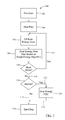
- FIG. 2 shows a flow chart illustrating an exemplary method 100 for inspecting container 12 , such as break bulk cargo, to identify one or more objects concealed within container 12 and performing additional processing to verify whether each identified object contains a target material, such as explosive material.
- a target material such as explosive material.
- a prescan stage 102 is employed to perform a scan of container 12 .
- a suitable X-ray radiographic scan of container 12 is performed during prescan stage 102 to identify locations within container 12 that require CT inspection.
- a first or initial slice plan is generated 104 .
- one or more locations within container 12 identified based on a dual energy algorithm are scanned 106 using a dual energy CT scanner.
- Dual energy CT scan 106 includes a low energy scan and a high energy scan of one or more identified locations within container 12 .
- An updated slice plan is generated 108 based on a single-energy algorithm.
- Data collection system 18 and/or processor 20 processes the data collected to facilitate the determination 110 whether one or more additional slices are required.
- the corresponding identified location within container 12 is scanned using the dual energy CT scanner.
- An updated dual energy slice plan is generated 108 using a single-energy algorithm. Such process is repeated until no additional slice is required 114 , and scanning system 10 makes a determination 116 based on available information to clear 118 container 12 or generate an alarm signal indicating that an object within container 12 may include a target material.
- additional processing is performed 124 employing a dual-energy Post-Detection Classifier or other suitable algorithm to clear 126 the object alarm status and eject 120 container 12 or to maintain the object alarm status.
- FIG. 3 shows a flow chart illustrating an alternative exemplary method 200 for inspecting container 12 , such as checked luggage, to identify one or more objects concealed within container 12 and performing processing of each identified object to verify whether the object is a prohibited item, e.g., a target material, such as an explosive material.
- a target material such as an explosive material
- a prescan stage 202 is employed to perform a scan of container 12 .
- a suitable X-ray radiographic scan of container 12 is performed during prescan stage 202 to identify locations within container 12 that require CT inspection.
- a first or initial slice plan is generated 204 .
- one or more locations within container 12 identified based on a dual energy algorithm are scanned 206 using a dual energy CT scanner.
- Dual energy CT scan 206 includes a low energy scan and a high energy scan of one or more identified locations within container 12 .
- An updated slice plan is generated 208 based on a dual-energy algorithm.
- Data collection system 18 and/or processor 20 processes the data collected to facilitate the determination 210 whether one or more additional slices are required.
- scanning system 10 makes a determination based on available information to clear and eject 218 container 12 from within scanning system 10 .
- the corresponding identified location within container 12 is dual energy CT scanned 206 using the dual energy CT scanner.
- An updated dual energy slice plan is generated 208 using the high energy scan information and the low energy information obtained during CT scan 206 . Such process is repeated until no additional slice is required 214 , and scanning system 10 makes a determination based on available information to clear and eject 218 container 12 from within scanning system 10 .
- FIG. 4 shows a flow chart illustrating an alternative exemplary method 300 for inspecting container 12 , such as checked luggage, to identify one or more objects concealed within container 12 and performing a targeted scan of each identified object to verify whether the object is a safety threat, e.g., a target material, such as an explosive material.
- a safety threat e.g., a target material, such as an explosive material.
- a prescan stage 302 is employed to perform a scan of container 12 .
- a suitable X-ray radiographic scan of container 12 is performed during prescan stage 302 to identify locations within container 12 that may require additional inspection.
- a first or initial slice plan is generated 304 .
- scanned data corresponding to additional cross-sectional slices of container 12 are obtained and transmitted to data collection system 18 (shown in FIG. 1 ).
- data collection system 18 and/or processor 20 shown in FIG. 1 ) processes the data collected to facilitate identifying one or more objects 28 of interest within container 12 .
- only identified objects 28 are dual energy CT scanned.
- suitable system throughput is maintained because only slices having a high probability of identifying a target material are dual energy CT scanned.
- CT scan 306 includes a low energy scan or a high energy scan of each identified location within container 12 .
- a single energy slice plan is generated 308 using the scan information obtained during CT scan 306 .
- the high energy scan information including CT number information is utilized to facilitate determining whether object 28 includes a target material, such as an explosive material.
- each object 28 is dual energy CT scanned 320 based on a single energy algorithm or a dual energy algorithm.
- Dual energy CT scan 320 includes one or more low energy scans and one or more high energy scans of each identified object 28 of interest within container 12 for slices associated with object 28 .
- the low energy scan information and/or the high energy scan information may be utilized to facilitate determining whether each object 28 of interest includes a target material.
- scanned data corresponding to additional cross-sectional slices of each object 28 are obtained and transmitted to data collection system 18 .
- Data collection system 18 and/or processor 20 calculates the CT number distribution and/or the atomic number distribution within the cross-sectional slices of object 28 and processes the data collected to facilitate determining whether object 28 includes a target material. Processor 20 then determines 312 whether one or more additional slices are required. If an additional slice is required 316 , dual energy CT scan 320 is performed to generate additional high energy information and additional low energy information utilized to facilitate determining whether object 28 includes a target material.
- FIG. 5 shows a flow chart illustrating an exemplary method 400 for inspecting container 12 , such as checked luggage, to identify one or more objects concealed within container and performing a targeted scan of each identified object to verify whether the object is a safety threat, e.g., a target material, such as an explosive material.
- a safety threat e.g., a target material, such as an explosive material.
- a prescan stage 402 is employed to perform a scan of container 12 .
- a suitable X-ray radiographic scan of container 12 is performed during prescan stage 402 to identify locations within container 12 that may require additional inspection.
- a first or initial slice plan is generated 404 .
- scanned data corresponding to additional cross-sectional slices of container 12 are obtained and transmitted to data collection system 18 (shown in FIG. 1 ).
- data collection system 18 and/or processor 20 shown in FIG. 1 ) processes the data collected to facilitate identifying one or more locations of interest within container 12 . In this embodiment, only the identified locations are CT scanned to facilitate maintaining system throughput.
- one or more identified locations within container 12 are single energy CT scanned 406 based on a single energy algorithm.
- Single energy CT scan 406 includes a low energy scan or a high energy scan of one or more identified locations within container 12 .
- a single energy slice plan is generated 408 using the scan information, such as the high energy scan information obtained by the high energy scan, or, alternatively, the low energy scan information obtained by the low energy scan, obtained during single energy CT scan 406 .
- the high energy scan information includes CT number information that may be utilized to facilitate determining whether object 28 includes a target material, such as an explosive material.
- scanned data corresponding to additional cross-sectional slices of container 12 are obtained and transmitted to data collection system 18 .
- Data collection system 18 and/or processor 20 calculates the CT number distribution within the cross-sectional slices of container 12 and processes the data collected to facilitate identifying one or more locations of interest within container 12 .
- Processor 20 determines 410 whether one or more additional slices are required to obtain additional scan information. If an additional slice is required 412 , single energy CT scan 406 is performed to generate additional high energy information utilized to facilitate identifying locations that may include objects 28 of interest within container 12 .
- scanning system 10 employs an algorithm to determine 416 , based on available information, whether to generate an alarm signal or to clear container 12 . If container 12 is cleared 418 , container 12 is ejected 420 from within scanning system 10 . However, if an alarm signal is generated 422 , a post detection dual energy CT scan 424 of container 12 is performed. Post detection dual energy CT scan 424 scans only identified locations within container 12 suspected of including object 28 of interest. Post detection dual energy CT scan 424 includes high energy scan information corresponding to the CT number of object 28 . A combination of the low energy scan information and the high energy scan information corresponds to the atomic number of object 28 .
- the scan information obtained during post detection dual energy CT scan 424 is utilized to determine whether to clear and eject 420 container 12 from within scanning system 10 . More specifically, during post detection classification both the high energy scan information related to the CT number of object 28 and the combination of the low energy scan information and the high energy scan information related to the atomic number of object 28 are collected and processed to determine 426 whether object 28 includes a target material, such as an explosive material.
- a target material such as an explosive material.
- container 12 is subject to further inspection. However, if, no additional alarm signal was generated 428 , container 12 is ejected 420 from within scanning system 10 . If one or more additional alarm signals were generated 430 , container 12 is scanned at post detection dual energy CT scan 424 . Such process continues until scanning system 10 determines that at least one object 28 concealed within container 12 includes an explosive material or all objects 28 that resulted in an alarm signal generation have been scanned by post detection dual energy CT scan 424 . If scanning system 10 determines that at least one object 28 includes a target material, such as an explosive material, container 12 is removed 425 from within scanning system and subject to additional inspection. If, upon scanning each object 28 responsible for generating an alarm signal, no object 28 has been determined to include an explosive material, container 12 is ejected 420 from within scanning system 10 .
- target material such as an explosive material
- the algorithm includes a queuing query to determine 432 whether another container 12 is queued for inspection. If scanning of container 12 generates an alarm signal 422 and one or more containers 12 are queued 434 for scanning by scanning system 10 , container 12 is ejected 420 from within scanning system 10 and subject to additional inspection, such as by a TSA agent operating scanning system 10 . However, if no other container 12 is queued 436 , post detection dual energy CT scan 424 of container 12 is performed and the process continues as described above. In this embodiment, system throughput is maintained or increased by skipping the clearing stage including the dual energy CT scan of object(s) 28 responsible for generating an alarm signal if additional containers 12 are queued for scanning. Containers 12 that generate an alarm signal are removed from within scanning system 10 and physically inspected by a TSA agent, allowing scanning system 10 to continue to scan additional containers 12 queued for inspection.
- a computed tomography (CT) scanning system for automatically inspecting a container for a target material is configured to perform an initial radiographic scan of the container. Based at least partially on projection data generated during the initial radiographic scan, a slice plan with at least one location within the container that may require a single energy CT inspection is identified. The slice plan is adjusted as additional single energy scans are performed. Once the slice plan requires no more single energy scans, an automatic detection algorithm is used to identify objects of interest. If one or more objects of interest are identified, a slice plan of the at least one object of interest is generated and a dual energy CT scan of the at least one identified object of interest is performed.
- CT computed tomography
- the dual energy CT scan includes a low energy scan of the at least one identified object of interest and a high energy scan of the at least one identified object of interest. Based at least partially on dual energy scan information generated during the dual energy CT scan, a determination is made whether the object contains a target material. If one or more objects contain the target material an alarm signal is generated for the container.
- X-ray detector 16 is an energy sensitive detector, such a CZT or a dual-layer detector.
- the scan data is collected at the high energy distribution and X-ray detector 16 provides the dual energy scan information to determine the effective atomic number of the inspected object.
- the layers are optimized to produce similar statistical accuracy for both the high energy distribution and the low energy distribution.
- an operating mode for energy-sensitive X-ray detector 16 includes performing CT scans at locations identified by the prescan stage. Scanning system 10 produces an alarm/clear decision with all the available information.
- the operating mode includes CT scanning container 12 identified by the prescan stage employing a single energy algorithm, which produces an alarm/clear decision. If one or more objects generate an alarm signal, additional image analysis using dual energy scan information is performed to clear or confirm the alarm signal.
- the above-described CT scanning system and method for inspecting containers include a radiographic prescan stage to identify areas or locations of interest within the container that are suspected of including a target material.
- a CT scanning performed at these identified locations facilitates identifying one or more objects contained within the container as target materials. Additional processing is performed on each identified object to confirm or clear the target material.
- the system includes a radiographic scanner to identify areas of interest, a first high-energy CT scanning process to facilitate identifying one or more objects contained within the container, and a second low-energy or dual-energy CT scanning process for determining whether each object includes a target material.
- dual energy scanning is achieved by collecting data for the same slice at a low energy distribution and then a high energy distribution without moving the object.
- the data is collected using a 180° fan angle at both energy distributions.
- data is collected at at least one full rotation for the low energy distribution and at least a 180° fan angle for the high energy distribution, allowing employment of the same projection angles for both energy distributions to facilitate reconstructing the images.
- a current for the low energy scanning is increased to maintain the same or similar power as the high energy scanning.
- a number of revolutions for the low energy scanning is increased. For example, if a high energy voltage is 2V and a high energy current is I, switching to a low energy voltage, such as V, increases a low energy current to 2I, which results in an increase by a factor of 2 the number of low energy X-rays. If the number of rotations is increased from 0.5 to 2, the number of low energy X-rays increases by a factor of 4. Both changes result in an 8-fold increase in low energy X-rays.
- the above-described system and method facilitate inspecting containers efficiently and reliably. More specifically, utilization of dual-energy scanning produces an additional signature, namely atomic number, which facilitates increasing system performance including increasing detection of objects of interest and/or reducing false alarms.
- conventional inspection systems produce images of the CT number, which is approximately proportional to the density, of the scanned object contents.
- the detection algorithms utilized in the conventional inspection systems are primarily based on the detection of CT number characteristics of the object of interest. Often times, benign materials have similar CT numbers and masses as objects of interest. Thus, as benign materials are inspected, false alarms may be generated.
- dual energy scan information provides atomic number information to facilitate identifying objects of interest and distinguishing these objects of interest from benign materials to reduce the false alarm rate.
- Implementation of at least a portion of the above-described system does not require sophisticated power supplies and/or detectors. Further, unlike other dual energy approaches, the low voltages and the high voltages are not an average voltage resulting from slow switching times. The above-described system also facilitates reducing photon starvation for the low energy inspection, which would otherwise reduce the system capability for reducing the false alarm rate.
- Exemplary embodiments of a system and a method for inspecting containers are described above in detail.
- the system and the method are not limited to the specific embodiments described herein, but rather, components of the system and/or the steps of the method may be utilized independently and separately from other components and/or steps described herein. Further, the described system components and/or method steps can also be defined in, or used in combination with, other systems and/or methods, and are not limited to practice with only the system and method as described herein.
Abstract
Description
Claims (28)
Priority Applications (3)
| Application Number | Priority Date | Filing Date | Title |
|---|---|---|---|
| US12/006,119 US7839971B2 (en) | 2007-12-31 | 2007-12-31 | System and method for inspecting containers for target material |
| EP08869515.0A EP2227709B1 (en) | 2007-12-31 | 2008-12-10 | System and method for inspecting containers for target material |
| PCT/US2008/086237 WO2009088625A2 (en) | 2007-12-31 | 2008-12-10 | System and method for inspecting containers for target material |
Applications Claiming Priority (1)
| Application Number | Priority Date | Filing Date | Title |
|---|---|---|---|
| US12/006,119 US7839971B2 (en) | 2007-12-31 | 2007-12-31 | System and method for inspecting containers for target material |
Publications (2)
| Publication Number | Publication Date |
|---|---|
| US20090168949A1 US20090168949A1 (en) | 2009-07-02 |
| US7839971B2 true US7839971B2 (en) | 2010-11-23 |
Family
ID=40798445
Family Applications (1)
| Application Number | Title | Priority Date | Filing Date |
|---|---|---|---|
| US12/006,119 Active 2028-03-01 US7839971B2 (en) | 2007-12-31 | 2007-12-31 | System and method for inspecting containers for target material |
Country Status (3)
| Country | Link |
|---|---|
| US (1) | US7839971B2 (en) |
| EP (1) | EP2227709B1 (en) |
| WO (1) | WO2009088625A2 (en) |
Cited By (4)
| Publication number | Priority date | Publication date | Assignee | Title |
|---|---|---|---|---|
| US20110193558A1 (en) * | 2010-02-02 | 2011-08-11 | Morpho Detection, Inc. | Passenger scanning systems for detecting contraband |
| US20130343624A1 (en) * | 2012-06-22 | 2013-12-26 | General Electric Company | Methods and systems for performing model-based iterative reconstruction |
| US20140169520A1 (en) * | 2012-12-19 | 2014-06-19 | Morpho Detection, Inc. | Systems and methods for dual energy imaging |
| US9091628B2 (en) | 2012-12-21 | 2015-07-28 | L-3 Communications Security And Detection Systems, Inc. | 3D mapping with two orthogonal imaging views |
Families Citing this family (5)
| Publication number | Priority date | Publication date | Assignee | Title |
|---|---|---|---|---|
| US8198587B2 (en) * | 2008-11-24 | 2012-06-12 | Varian Medical Systems, Inc. | Compact, interleaved radiation sources |
| US9435900B2 (en) * | 2011-06-08 | 2016-09-06 | The Board Of Trustees Of The Leland Stanford Junior University | X-ray system utilizing alternating spectrum x-ray source in conjuction with a fixed spectrum separation filter approval |
| JP6763301B2 (en) | 2014-09-02 | 2020-09-30 | 株式会社ニコン | Inspection equipment, inspection methods, inspection processing programs and structure manufacturing methods |
| EP3190402B1 (en) * | 2014-09-02 | 2023-10-18 | Nikon Corporation | Measurement processing device, x-ray inspection apparatus, method for manufacturing a structure, measurement processing method and measurement processing program |
| CN110927808A (en) * | 2019-11-28 | 2020-03-27 | 武汉艾崴科技有限公司 | Large-scale movable type foldable X-ray scanning robot with detection frame |
Citations (7)
| Publication number | Priority date | Publication date | Assignee | Title |
|---|---|---|---|---|
| US4029963A (en) | 1976-07-30 | 1977-06-14 | The Board Of Trustees Of Leland Stanford Junior University | X-ray spectral decomposition imaging system |
| US5182764A (en) | 1991-10-03 | 1993-01-26 | Invision Technologies, Inc. | Automatic concealed object detection system having a pre-scan stage |
| US5367552A (en) | 1991-10-03 | 1994-11-22 | In Vision Technologies, Inc. | Automatic concealed object detection system having a pre-scan stage |
| US20030147489A1 (en) | 2002-02-06 | 2003-08-07 | Bijjani Richard R. | Method and apparatus for transmitting information about a target object between a prescanner and a CT scanner |
| US20050031076A1 (en) * | 2001-04-03 | 2005-02-10 | L-3 Communications Security And Detections System | Remote baggage screening method |
| US7116751B2 (en) | 2003-04-02 | 2006-10-03 | Reveal Imaging Technologies, Inc. | System and method for resolving threats in automated explosives detection in baggage and other parcels |
| US7224763B2 (en) | 2004-07-27 | 2007-05-29 | Analogic Corporation | Method of and system for X-ray spectral correction in multi-energy computed tomography |
-
2007
- 2007-12-31 US US12/006,119 patent/US7839971B2/en active Active
-
2008
- 2008-12-10 WO PCT/US2008/086237 patent/WO2009088625A2/en active Application Filing
- 2008-12-10 EP EP08869515.0A patent/EP2227709B1/en not_active Not-in-force
Patent Citations (8)
| Publication number | Priority date | Publication date | Assignee | Title |
|---|---|---|---|---|
| US4029963A (en) | 1976-07-30 | 1977-06-14 | The Board Of Trustees Of Leland Stanford Junior University | X-ray spectral decomposition imaging system |
| US5182764A (en) | 1991-10-03 | 1993-01-26 | Invision Technologies, Inc. | Automatic concealed object detection system having a pre-scan stage |
| US5367552A (en) | 1991-10-03 | 1994-11-22 | In Vision Technologies, Inc. | Automatic concealed object detection system having a pre-scan stage |
| US20050031076A1 (en) * | 2001-04-03 | 2005-02-10 | L-3 Communications Security And Detections System | Remote baggage screening method |
| US20030147489A1 (en) | 2002-02-06 | 2003-08-07 | Bijjani Richard R. | Method and apparatus for transmitting information about a target object between a prescanner and a CT scanner |
| US7116751B2 (en) | 2003-04-02 | 2006-10-03 | Reveal Imaging Technologies, Inc. | System and method for resolving threats in automated explosives detection in baggage and other parcels |
| US20070121783A1 (en) | 2003-04-02 | 2007-05-31 | Reveal Imaging Technologies | System and method for resolving threats in automated explosives detection in baggage and other parcels |
| US7224763B2 (en) | 2004-07-27 | 2007-05-29 | Analogic Corporation | Method of and system for X-ray spectral correction in multi-energy computed tomography |
Non-Patent Citations (1)
| Title |
|---|
| European Patent Office, Patent Cooperation Treaty, Invitation to Pay Additional Fees and including Communication Relating to the Results of the Partial International Search Report for Application No. PCT/US2008/086237, Sep. 25, 2009, 10 pages. |
Cited By (5)
| Publication number | Priority date | Publication date | Assignee | Title |
|---|---|---|---|---|
| US20110193558A1 (en) * | 2010-02-02 | 2011-08-11 | Morpho Detection, Inc. | Passenger scanning systems for detecting contraband |
| US20130343624A1 (en) * | 2012-06-22 | 2013-12-26 | General Electric Company | Methods and systems for performing model-based iterative reconstruction |
| US8923583B2 (en) * | 2012-06-22 | 2014-12-30 | General Electric Company | Methods and systems for performing model-based iterative reconstruction |
| US20140169520A1 (en) * | 2012-12-19 | 2014-06-19 | Morpho Detection, Inc. | Systems and methods for dual energy imaging |
| US9091628B2 (en) | 2012-12-21 | 2015-07-28 | L-3 Communications Security And Detection Systems, Inc. | 3D mapping with two orthogonal imaging views |
Also Published As
| Publication number | Publication date |
|---|---|
| EP2227709A2 (en) | 2010-09-15 |
| US20090168949A1 (en) | 2009-07-02 |
| WO2009088625A2 (en) | 2009-07-16 |
| EP2227709B1 (en) | 2016-04-13 |
| WO2009088625A3 (en) | 2010-01-21 |
Similar Documents
| Publication | Publication Date | Title |
|---|---|---|
| EP2227709B1 (en) | System and method for inspecting containers for target material | |
| US7492855B2 (en) | System and method for detecting an object | |
| US6345113B1 (en) | Apparatus and method for processing object data in computed tomography data using object projections | |
| US10598812B2 (en) | Systems and methods for the automatic detection of lithium batteries in cargo, baggage, parcels, and other containers | |
| US7324625B2 (en) | Contraband detection systems using a large-angle cone beam CT system | |
| US7277577B2 (en) | Method and system for detecting threat objects using computed tomography images | |
| US7539337B2 (en) | Method of and system for splitting compound objects in multi-energy computed tomography images | |
| EP2676128B1 (en) | System and method for multi-scanner x-ray inspection | |
| US20080170655A1 (en) | Computed tomography cargo inspection system and method | |
| US9036782B2 (en) | Dual energy backscatter X-ray shoe scanning device | |
| US8090150B2 (en) | Method and system for identifying a containment vessel | |
| US7801348B2 (en) | Method of and system for classifying objects using local distributions of multi-energy computed tomography images | |
| WO2015171943A1 (en) | Image-based object detection and feature extraction from a reconstructed charged particle image of a volume of interest | |
| US20080181357A1 (en) | Combined computed tomography and nuclear resonance fluorescence cargo inspection system and method | |
| JP2007516435A (en) | System and method for detecting contraband goods | |
| US20090034792A1 (en) | Reducing latency in a detection system | |
| US7474786B2 (en) | Method of and system for classifying objects using histogram segment features of multi-energy computed tomography images | |
| US20110091013A1 (en) | Method and apparatus for detecting a particular material in an object by means of electromagnetic radiation | |
| US20090226032A1 (en) | Systems and methods for reducing false alarms in detection systems | |
| US20060251209A1 (en) | Energy sensitive x-ray system and method for material discrimination and object classification | |
| Lu | The utility of X-ray dual-energy transmission and scatter technologies for illicit material detection | |
| US20090087012A1 (en) | Systems and methods for identifying similarities among alarms | |
| US20090232277A1 (en) | System and method for inspection of items of interest in objects | |
| Bjorkholm et al. | Explosives detection using three-dimensional computer-assisted image analysis | |
| US8254676B2 (en) | Methods and systems for identifying a thin object |
Legal Events
| Date | Code | Title | Description |
|---|---|---|---|
| AS | Assignment |
Owner name: GE HOMELAND PROTECTION, INC., CALIFORNIA Free format text: ASSIGNMENT OF ASSIGNORS INTEREST;ASSIGNORS:BENDAHAN, JOSEPH;GARMS, WALTER IRVING;GU, MENGQIAN;REEL/FRAME:020434/0175;SIGNING DATES FROM 20080117 TO 20080122 |
|
| AS | Assignment |
Owner name: MORPHO DETECTION, INC., CALIFORNIA Free format text: CHANGE OF NAME;ASSIGNOR:GE HOMELAND PROTECTION, INC.;REEL/FRAME:023517/0089 Effective date: 20091001 |
|
| STCF | Information on status: patent grant |
Free format text: PATENTED CASE |
|
| AS | Assignment |
Owner name: MORPHO DETECTION, LLC, CALIFORNIA Free format text: CHANGE OF NAME;ASSIGNOR:MORPHO DETECTION, INC.;REEL/FRAME:032122/0067 Effective date: 20131230 |
|
| AS | Assignment |
Owner name: MORPHO DETECTION, LLC, CALIFORNIA Free format text: CORRECTIVE ASSIGNMENT TO CORRECT THE THE PURPOSE OF THE CORRECTION IS TO ADD THE CERTIFICATE OF CONVERSION PAGE TO THE ORIGINALLY FILED CHANGE OF NAME DOCUMENT PREVIOUSLY RECORDED ON REEL 032122 FRAME 67. ASSIGNOR(S) HEREBY CONFIRMS THE THE CHANGE OF NAME;ASSIGNOR:MORPHO DETECTION, INC.;REEL/FRAME:032470/0682 Effective date: 20131230 |
|
| FPAY | Fee payment |
Year of fee payment: 4 |
|
| MAFP | Maintenance fee payment |
Free format text: PAYMENT OF MAINTENANCE FEE, 8TH YEAR, LARGE ENTITY (ORIGINAL EVENT CODE: M1552) Year of fee payment: 8 |
|
| MAFP | Maintenance fee payment |
Free format text: PAYMENT OF MAINTENANCE FEE, 12TH YEAR, LARGE ENTITY (ORIGINAL EVENT CODE: M1553); ENTITY STATUS OF PATENT OWNER: LARGE ENTITY Year of fee payment: 12 |