US7818153B2 - System and method for constraining a graphical hand from penetrating simulated graphical objects - Google Patents
System and method for constraining a graphical hand from penetrating simulated graphical objects Download PDFInfo
- Publication number
- US7818153B2 US7818153B2 US12/346,686 US34668608A US7818153B2 US 7818153 B2 US7818153 B2 US 7818153B2 US 34668608 A US34668608 A US 34668608A US 7818153 B2 US7818153 B2 US 7818153B2
- Authority
- US
- United States
- Prior art keywords
- boundaries
- graphical
- haptic
- hand
- virtual
- Prior art date
- Legal status (The legal status is an assumption and is not a legal conclusion. Google has not performed a legal analysis and makes no representation as to the accuracy of the status listed.)
- Expired - Fee Related
Links
Images


Classifications
-
- G—PHYSICS
- G06—COMPUTING; CALCULATING OR COUNTING
- G06F—ELECTRIC DIGITAL DATA PROCESSING
- G06F3/00—Input arrangements for transferring data to be processed into a form capable of being handled by the computer; Output arrangements for transferring data from processing unit to output unit, e.g. interface arrangements
- G06F3/01—Input arrangements or combined input and output arrangements for interaction between user and computer
- G06F3/011—Arrangements for interaction with the human body, e.g. for user immersion in virtual reality
-
- G—PHYSICS
- G06—COMPUTING; CALCULATING OR COUNTING
- G06T—IMAGE DATA PROCESSING OR GENERATION, IN GENERAL
- G06T19/00—Manipulating 3D models or images for computer graphics
- G06T19/20—Editing of 3D images, e.g. changing shapes or colours, aligning objects or positioning parts
-
- G—PHYSICS
- G06—COMPUTING; CALCULATING OR COUNTING
- G06T—IMAGE DATA PROCESSING OR GENERATION, IN GENERAL
- G06T2210/00—Indexing scheme for image generation or computer graphics
- G06T2210/21—Collision detection, intersection
-
- G—PHYSICS
- G06—COMPUTING; CALCULATING OR COUNTING
- G06T—IMAGE DATA PROCESSING OR GENERATION, IN GENERAL
- G06T2210/00—Indexing scheme for image generation or computer graphics
- G06T2210/28—Force feedback
-
- G—PHYSICS
- G06—COMPUTING; CALCULATING OR COUNTING
- G06T—IMAGE DATA PROCESSING OR GENERATION, IN GENERAL
- G06T2219/00—Indexing scheme for manipulating 3D models or images for computer graphics
- G06T2219/20—Indexing scheme for editing of 3D models
- G06T2219/2016—Rotation, translation, scaling
-
- G—PHYSICS
- G06—COMPUTING; CALCULATING OR COUNTING
- G06T—IMAGE DATA PROCESSING OR GENERATION, IN GENERAL
- G06T2219/00—Indexing scheme for manipulating 3D models or images for computer graphics
- G06T2219/20—Indexing scheme for editing of 3D models
- G06T2219/2021—Shape modification
Definitions
- This invention relates generally to systems, apparatuses, and methods for simulation and training using interactive computer graphics.
- Some of the hardware interfaces include force-feedback joysticks and steering wheels.
- Two companies which have introduced API's and SDK's for their joystick/steering wheel peripherals include Immersion Corporation and Cybernet Systems.
- Immersion markets its I-FORCETM API, a programming interface that lets developers simulate various force-feedback effects such as: impacts, recoils, vibrations, springs, etc. It has been integrated into Microsoft's DirectX specification [4].
- Cybernet has introduced its CyberImpactTM SDK, with comparable features to Immersion's I-FORCE.
- SensAble Technologies Another company that produces a haptic SDK is SensAble Technologies.
- SensAble markets a 3-degree-of-freedom (3DOF) force-feedback stylus called the PHANToMTM and their accompanying SDK is named GhoStTM [5].
- Ghost is an object-oriented toolkit that represents the haptic environment as a hierarchical collection of geometric objects (spheres, cubes, cylinders, etc.) and spatial effects (springs, dampers, vibrations, etc.)
- the ghost toolkit includes a spring model for presenting a single graphical point, as controlled by the PHANToM, from penetrating a graphical object.
- Noma and Miyasato propose a technique similar to ghost, but also limit their technique to a single, non-articulated point [7].
- the first SDK's and API's to appear have been associated with relatively simple devices such as joysticks, steering wheels and 3D styli.
- relatively simple devices such as joysticks, steering wheels and 3D styli.
- degrees of freedom of movement of the device are limited, or a single point is interacting with the environment.
- comparable software for whole-hand input interfaces has lagged behind because of the inherent complexity of the whole-hand interaction paradigm, with its multiple constraints and multiple, articulated degrees of freedom.
- whole-hand input devices present a greater challenge to integrate, they provide an extremely appealing advantage for interaction. What better way to manipulate complex virtual objects than to just “reach in and grab them?”
- Virtual Technologies, Inc. has offered its VirtualHand® Software Library, while 5DT has offered an API for its DataGlove. Both let the user display a graphical hand on the screen that mimics the glove wearer's movement, but they do not provide manipulation capabilities; such capabilities are presently left to the user to develop.
- Inventive features of the subject invention include enhanced manipulation capabilities, the ability to prevent the virtual hand from penetrating grasped objects and virtual walls, and enabling dynamic interaction between the virtual hand and various controls.
- the subject invention includes a structure and method for determining the configuration of a graphical hand and arm based on the measurement of a controlling physical hand and arm, specifically where the graphical hand and arm are constrained in movement upon coming into contact with an immoveable graphical object or other simulated graphical impediment, but where the physical hand and arm are not similarly restrained in their movement.
- the invention provides a system for moving a simulated multi-articulated structure in relation to the movement of an analogous physical multi-articulated structure, where the simulated structure moves in a simulated environment having a simulated impediment to free motion, where the physical structure moves in an environment lacking an analogous physical impediment, and where in one embodiment the system includes a device for measuring the configuration of the physical structure and the spatial placement of the physical structure relative to an inertial reference frame and providing digitized signals associated with the configuration and spatial placement; and a data processor, including data related to the spatial placement of the simulated impediment, for receiving the digitized signals and modifying the signals to generate a set of modified signals specifying the configuration and spatial placement of the simulated structure, whereby the free motion of the simulated structure is impeded when encountering the simulated impediment.
- the invention provides a method for moving a simulated multi-articulated structure in a graphical environment, having an impediment to free motion, in relation to the movement of an analogous physical multi-articulated structure in a physical environment lacking the impediment, where in one embodiment the inventive method includes the steps of generating digitized signals representing the configuration and spatial placement of the physical structure and transferring the digitized signals to a data processor; and in the data processor, recording the spatial placement of the impediment, generating modified signals from the digitized signals specifying the configuration and spatial placement of the graphical structure, and impeding the free motion of the simulated structure when the simulated structure encounters the impediment.
- FIG. 1 shows a overview of an embodiment of the VirtualHand toolkit.
- FIG. 2 shows a demonstration (computer screen capture) using the VirtualHand Toolkit to generate a graphical hand which is constrained to not penetrate a control panel and associated buttons.
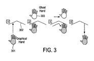
- FIG. 3 shows an embodiment of where the graphical hand is following constraints as it tries to track the ghost hand.
- FIG. 4 is a diagrammatic view of an embodiment of a joint-link model of a human hand and forearm.
- FIG. 5 is a diagrammatic side view of an embodiment of a spring model for the graphical hand, including a joint-link model of the human hand and forearm, with associated joint springs and tracker springs.
- FIG. 6 is a diagrammatic view of an embodiment of: (A) ghost hand and (B) graphical hand with springs compressed due to constraint of the compliant wall.
- FIG. 7 is a diagrammatic view of an embodiment of a spring-mass-dashpot model for the hand for use in dynamic situations.
- FIGS. 8A-8F are diagrammatic views of various embodiments of a spring models for the graphical hand.
- FIG. 9 is a diagrammatic side view of an embodiment of a spring model for a portion of a graphical human figure, with associated joint springs and tracker springs.
- FIG. 10 is a diagrammatic side view of an embodiment of a spring model for a portion of a generic mechanical structure, with associated joint springs and tracker springs.
- FIG. 11 is a diagrammatic view of two objects, A and B, with various critical elements identified.
- FIG. 12 is a diagrammatic view of objects A, with various critical elements identified.
- FIG. 13 is a diagrammatic view of two intersecting objects, A and B, with various critical elements identified.
- FIG. 14 is a diagrammatic view of the palm of the hand.
- FIG. 15 is a diagrammatic view of a facet with surrounding voronoi planes.
- FIG. 16 is a diagrammatic side view of a finger, with links and joint angles defined.
- FIGS. 17A and 17B are diagrammatic side views of a finger: (A) before calculating joint adjustments to back the finger out from the wall, and (B) after performing such calculations.
- FIG. 18 is a diagrammatic side view of a physical hand and instrumented glove continuing to move after a graphical hand, being controlled by the glove, is caused to stop at a simulated table by the inventive constraining method.
- the field of virtual reality typically uses an instrumented glove or other hand-measurement apparatus to measure the movements of a user's physical hand and produce a graphical rendition of the hand (i.e., graphical hand) on a computer screen.
- a graphical rendition of the hand i.e., graphical hand
- the goal of rendering the graphical hand is to allow contact and interaction between the graphical hand and a graphical object to be controlled or manipulated.
- the most common drawback to such a graphical simulation occurs when the physical hand does not possess any force feedback, or lacks adequate force feedback, to stop the physical hand and fingers from moving once the graphical hand has contacted a graphical impediment, such as an immovable graphical object.
- the graphical hand associated with the physical hand will also continue to move, and thus penetrate the graphical object, greatly reducing the desired perception of the simulation that one is using their hand to interact with a real, solid object.
- An alternative solution, which finds use whenever there is non-existing, or insufficient, force feedback to the physical hand is where the graphical hand ceases to exactly follow the physical hand.
- a separate computer calculation might change the configuration, orientation or spatial placement, of the graphical hand such that it doesn't follow the measured physical hand, and such that the graphical hand obeys laws of physics during interaction with graphical objects.
- a graphical finger might bend backward such that it doesn't penetrate a graphical wall.
- the simulation user or trainee wears an instrumented glove, i.e., a glove with sensors in it which measure the subtle movements of the fingers and hand.
- instrumented glove i.e., a glove with sensors in it which measure the subtle movements of the fingers and hand.
- the industry standard instrumented glove on the market today is known as the CyberGlove®, manufactured by Virtual Technologies, Inc., the Assignees of this patent application.
- Hand-movement data is transmitted from the instrumented glove to the computer, which in turn draws a graphical image of the hand, i.e., a virtual hand, which replicates the movements of the physical hand. This virtual hand can then be made to interact with graphical objects, such as simulated controls.
- the trainee learns how to operate the necessary controls, and also learns the effect the controls have on the high-level simulation.
- the problem with such simulations thus far has been the lack of intelligent software that realistically models the interactions between the virtual hand and an object to be manipulated.
- an all-to-typical scenario is that the virtual hand passes through the simulated control-panel surface as well as the controls that the virtual hand is intended to interact with.
- This unfortunately reduces the effectiveness of the simulation, since the trainee must change their manner of interaction to tailor to the limitations of the simulation.
- “bad habits” might be learned which enable the trainee to efficiently operate the simulation, but due to their disparity from reality, do not lead to skills which transfer to the ultimate real task.
- the subject invention provides an apparatus and method for constraining the movement of a graphical hand when the physical hand controlling the graphical hand does not have a similar physical constraint.
- the constraining technique may comprise use and analysis of a revolute-joint-link-spring model.
- an uncompressed/unextended spring position represents the corresponding measured joint angle or link position.
- the springs may follow any desirable non-linear function to obtain the desired result of allowing a graphical joint or link to deviate from what the corresponding measured joint or link provides.
- the method for constraining the graphical or simulated hand, body part or other articulated structure may be incorporated into software or firmware or other recording medium.
- the software is provided as a computer program product tangibly stored or recorded in a medium, such as a computer disk, CDROM, or other formats as are known in the art.
- FIG. 1 shows a diagrammatic view of the relationship between a Host Simulation Application ( 101 ) and Virtual Technologies' VirtualHand Toolkit (VHT), a portion of which is the subject of this invention.
- FIG. 1 also shows the relationship between the VHT and a Hand Manager module capable of constraining the virtual hand from penetrating graphical objects.
- a Hand-Interaction Scene Graph or more generally, the Interaction Scene Graph
- This hand-interaction scene graph interacts with a simulation's Master (a.k.a. World or Graphical) Scene Graph.
- a central module of the VirtualHand Toolkit architecture is the Hand-Interaction Simulator (HIS) 104 , which controls all hand interaction. It may be a separate process running on the host computer or, alternatively, if the Virtual Technologies CyberGrasp haptic-feedback system is used with the CyberGlove, the HIS may alternatively run on the CyberGrasp controller.
- the HIS comprises four major components:
- the HIS may also contain a State Manager ( 109 ) which is responsible for updating the state of each of the nodes that are in the scene graph.
- the state manager traverses the HISG tree, assigning new states (e.g., positions, velocities, etc.) to the various dynamic nodes. If the HIS is not a process running on the host computer, typically, the state manager updates the states of the HISG running in the HIS only, and not the HISG in the host application. In such a case, typically only the HISG in the HIS will have the ability to synchronize with the corresponding HISG in the host application.
- the collision manager has at least two objectives: to determine which two nodes (objects) are colliding, and to determine how deeply inside one another they are (i.e., the depth of penetration).
- the depth of penetration may be used to compute force feedback commands based on a stiffness model.
- DNSG Data Neutral Scene Graph
- the DNSG contains a node for each interactive element or other element of interest existing in either the graphical scene graph or the HISG. Elements of interest typically include elements which might change with time.
- the DNSG is typically the scene graph which is updated with each pass through the simulation loop. (That is, in effect, it becomes the “master” scene graph.)
- the DNSG passes the update information along to the corresponding node of the graphical scene graph and/or the HISG for updating.
- the HISG typically sends force commands, or local force patch approximations, to an I/O Daemon ( 106 ) (discussed below) running on a force controller.
- the correspondence ceases and the two hands may be modeled as linked via a network of virtual springs and dashpots. This ensures that when the user's real hand passes through a virtual wall and re-enters elsewhere, the graphical hand will be waiting at the appropriate location such that the two overlap again.
- step 1 the graphical hand is approaching a wall.
- step 2 the user's hand passes through the wall, but the graphical hand stops at the constraint.
- step 3 the user's hand moves sideways while the graphical hand tracks the wall.
- step 4 the user's hand backs away from the constraint and both hand models overlap.
- the I/O daemon runs as a background process and is responsible for communicating with the hardware devices.
- the daemon may acquire data from a Polhemus or Ascension electromagnetic tracker, and may also specify force and vibration setpoints to the CyberGrasp or CyberTouch (i.e., another Virtual Technologies haptic-feedback product) devices, respectively.
- the HIS communicates with the daemon via info packets that make the physical location of the daemon transparent to the user. It may run on a separate machine, such as the CyberGrasp controller, on the host itself, or any other computer on the network.
- the sensor stream is the data coming from the I/O daemon.
- the stream may include data from the CyberGlove and various 6D position trackers.
- an application ( 114 ) that is “interaction scene graph aware” is being written from the ground up using OpenGL, OpenInventor, etc.
- the interaction scene graph ( 113 ) may be directly incorporated into the master scene graph.
- the users might want to bypass the interaction scene graph altogether and write their own hand interaction simulation ( 116 ). In these instances, they can communicate directly with the I/O daemon to read data from the devices and control them directly vial a connection ( 115 ).
- FIG. 4 is a link-revolute-joint model of the human hand ( 400 ).
- the forearm link ( 401 ) is connected to the wrist yaw joint ( 402 ) which is connected to the wrist pitch joint ( 403 ).
- This joint is connected to the metacarpus link ( 404 ) which extends to connect to the thumb roll joint ( 405 ).
- This joint is connected to the thumb abduction joint ( 406 ) which is connected by the thumb metacarpal link ( 407 ) to the thumb metacarpal roll joint ( 408 ).
- This joint is connected to the thumb MP joint ( 409 ) which is connected by the thumb proximal phalanx ( 410 ) to the thumb IP joint ( 411 ), which is connected to the thumb distal phalanx ( 412 ).
- the hand metacarpus link ( 404 ) also connect to the joints at the base of each of the fingers ( 420 ). It connects to the index abduction joint ( 413 ), which connects to the index MP joint ( 414 ).
- the index MP joint is connected by the index proximal phalanx link ( 415 ) to the index.
- PI joint ( 416 ) which is connected by the index medial phalanx link ( 417 ) to the index DI joint ( 418 ) which ultimately connects to the index distal phalanx link ( 419 ).
- the structure is similar for each of the middle, ring and small fingers.
- Such a link-revolute joint hand model is described in Kramer's U.S. Pat. No. 5,482,056, “Determination of Thumb Position Using Measurements of Abduction and Rotation.”
- Link-revolute joint models for the entire human body are described in Kramer's U.S. Pat. No. 5,676,157, “Determination of Kinematically Constrained Multi-Articulated Structures.”
- FIG. 5 provides one embodiment for constraining the virtual hand at the surface of a virtual object.
- the concept is as follows. Associated with the measured physical hand of the user are two computer-simulated virtual hands, one is a graphical hand which is rendered, and the other is a “ghost” hand, which is not displayed, but given the measurements of the hand reproduces as precisely as possible the movements of the physical hand.
- the graphical hand ( 500 ) is modeled as having springs at each of the joints (e.g., one or more of the joints in FIG. 5 ), in addition to a spring at the fingertip and one at the wrist.
- the unstretched, i.e., zero position of each joint spring (e.g., ⁇ x 10 and ⁇ 20 , etc.) is defined by the corresponding joint angle of the ghost hand.
- the unstretched position of the wrist spring is defined by the position of the ghost wrist position, and the unstretched position of the fingertip spring is defined by the distance from a point about 1 ⁇ 4′′ into the fingertip out to the fingertip surface when it isn't in contact with an object.
- the position and orientation of the hand is measured to correspond to when the forearm attachment point ( 501 ) and the tracker position point ( 502 ) coincide with coordinate frames aligned, i.e., the corresponding orientation springs ( 503 ) and ( 504 ) are unstretched.
- the forearm attachment point and the tracker position point represent 3 degrees of freedom of orientation capability each, and thus have 3 rotary springs each.
- the tracker translation spring ( 505 ) is also unstretched and has zero length.
- the graphical hand is shown displaced from the measure position by x 1 .
- the tracker position point may be selected to be at a variety of locations, such as the forearm link (as is shown here), the metacarpus link, or even a point distal to the physical hand.
- the placement of the tracker position point will affect how simulated impediments will affect the movement of the hand.
- the forearm link is connected by the wrist joint ( 506 ), with rotary spring ( 507 ) to the metacarpus link ( 508 ).
- the wrist joint as shown typically comprises two orthogonal joints, a wrist flexion (pitch) and wrist abduction (yaw).
- the double joint is shown as a single wrist flexion joint.
- the rotary spring associated with this joint has spring constant k 2 , and is unstretched at an angle of ⁇ 20 .
- the metacarpus link is connected by the metacarpophalangeal joint ( 509 ), with corresponding rotary spring ( 510 ), to the proximal phalanx ( 511 ).
- the metacarpophalangeal joint actually comprises two orthogonal joints, one for flexure and one for abduction.
- this double joint is also shown as a single point.
- the rotary spring corresponding to the flexure of this joint has spring constant k 3 , and is unstretched at an angle of ⁇ 30 .
- the proximal phalanx is connected to the PI joint ( 512 ), which has a rotary spring ( 513 ) of spring constant k 4 and is unstretched at an angle of ⁇ 40 .
- the PI joint is also connected to the medial phalanx ( 514 ).
- the medial phalanx is connected by the DI joint ( 515 ) to the distal phalanx ( 516 ).
- the DI joint has a rotary spring ( 517 ) of spring constant k 5 and is unstretched at an angle of ⁇ 50 .
- the distal phalanx has a spring ( 518 ) to the fingertip ( 519 ), which represents the compliance of the fingertip.
- This spring has spring constant of k 6 , and is unstretched when at a length of x 60 .
- FIG. 6 shows the embodiment where the graphical hand contacts a compliant surface.
- FIG. 6A shows the ghost hand ( 600 ), which represents the true configuration of the physical hand, positioned relative to the object surface ( 601 ), while FIG. 6B shows the graphical hand ( 602 ) ultimately drawn after it “flexes.”
- the surface ( 603 ) is also shown to translate to the left ( 604 ) due to a modeled spring stiffness of the surface, where, in this example, the stiffness is on the order of stiffness of the hand springs.
- the fingertip of the hand ( 602 ) is shown to compress by an amount ⁇ x 6 ( 605 ), in addition to the other rotary joints angles also being modified.
- the tracker position is also shown to translate by an amount ⁇ x 1 ( 606 ).
- the graphical hand which may employ virtual springs at one or more of its joints such that it may bend naturally, is typically the hand used to actually compute simulated interaction forces for the embodiment where the CyberGrasp system, or some other haptic-feedback display, is used.
- the hand manager may include a generalized hand-constraint procedure that solves the hand-spring model given a list of constraining impediment collisions from the collision manager. It should be obvious to one skilled in the art of mathematics and dynamic simulation how to solve the multi-articulated spring model given a set of constraints.
- a separate “constraint model” may be associated with each colliding digital object, built up from a variety of shape primitives for which the hand manager knows how to interpret constraints. In this way an “object filter” is created which automatically fits such shape primitives to an arbitrary digital object to generate the constraint model.
- Such a constraint model may also be employed as a simplification of the true digital object for collision-detection and depth-of-penetration calculations for force-feedback.
- the hand-spring model provided thus far in FIGS. 5 and 6 is purely a static model, i.e., it does not account for dynamic properties of the hand or object, such as mass and damping. Thus, the response to impact between the hand and an object with mass can only be evaluated in the steady state; reactions to impacts must be ignored.
- FIG. 7 provides an extension of the hand-spring model to a hand-spring-mass-dashpot model for use in dynamic calculations.
- object m 7 ( 700 ) is traveling with velocity v o ( 701 ) at point p o ( 702 ) with normal n ( 703 ).
- Point p o is coupled to the lumped-mass model mass of m 7 via spring ( 704 ) with spring constant k 7 and dashpot ( 705 ) with damping b 7 .
- the finger ( 706 ) now has masses m 3 ( 707 ), m 4 ( 708 ) and m 5 ( 709 ) associated with the links ( 710 ), ( 711 ) and ( 712 ) as shown, rotary springs ( 713 ) and ( 714 ) with spring constants k 4 , k 5 , and rotary dashpots ( 715 ) and ( 716 ) with damping factors b 4 , b 5 associated with the joints as shown, and spring ( 717 ) and dashpot ( 718 ) k 6 and b 6 between the end of the finger solid link ( 712 ) and the contact point p F ( 719 ) at the fingertip which is traveling with velocity v F ( 720 ).
- the fingertip upon impact between the object and the finger, the fingertip will compress and the finger will recoil based upon the dynamics involved.
- the hand-interaction scene graph can be updated to include objects that are estimated to enter the sphere of interest and impact within the next few update cycles.
- the dynamic hand-spring model of FIG. 7 provides a model for determining hand constrains and manipulation of free-floating objects which might be moving at the time of contact with the virtual hand. In such cases, one might want to have a virtual finger recoil upon impact with the object, before the finger returns to a steady-state position.
- An example of such a free-floating object is a baseball, coffee cup or soda can.
- various physics-based manipulation algorithms may be employed without departing from the scope and intent of the invention.
- To determine a stable grasp of the free-floating object using the virtual hand requires solving a system comprising multiple objects which yield an over-constrained contact problem:
- the fingers and the palm area of the virtual hand are essentially six objects which interact with the object to be manipulated.
- FIG. 8 show various example in which a simulated graphical hand can be constrained to flex, translate and rotate relative to the measured ghost hand based on a curved surface impediment. These and other combinations of flexure, translation and rotation are obtained by adjusting the relative stiffnesses of modeled springs corresponding to the various articulated degrees of freedom of the finger joints, wrist, tracker, etc.
- FIG. 8A shows the top view ( 800 ) of a simulated graphical hand controlled by a physical hand.
- the fingernails ( 801 , 802 , 803 , 804 and 805 ), respectively, of the thumb ( 806 ), the index ( 807 ), the middle ( 808 ), the ring ( 809 ) and the small finger ( 810 ) are shown to provide perspective when the hand is rotated to an end view ( 811 ).
- the ghost hand separates from the simulated graphical hand ( 811 ) at the surface of the impediment ( 814 ) and moves to a first position ( 812 ).
- the ghost hand then translates to the side to a second position ( 825 ).
- the ghost hand has fingernails ( 815 , 816 , 817 , 818 and 819 ) of the thumb ( 820 ), the index ( 821 ), the middle ( 822 ), the ring ( 823 ) and the small finger ( 824 ). Note the subtle changes in orientation of the fingernails to help understand how the measured joint angles, orientation and spatial placement of the hand are modified in each figure to produce the resulting simulated graphical hand.
- FIG. 8B shows how the simulated hand moves to a new position ( 826 ) which, due to the curvature of the impediment surface, and the attractive force of the tracker translation spring shown here generically ( 813 ), is slightly closer to the ghost hand in its second position than the simulated hand was to the ghost hand in its first position.
- One technique to solve the model for the final configuration and spatial placement of the hand is, based on the choice of spring constants and joint-link structure, to determine what configuration and spatial placement corresponds to the lowest total spring energy state.
- the simulated hand is only allowed to translate along the same direction vector as originally caused the ghost hand to split off from the simulated hand.
- FIG. 8C shows an embodiment similar to 8 B; however, the fingers of the simulated hand are permitted to flex so that the simulated hand is closer to the ghost hand, again this position may be determined to result in a lower total spring energy state. Note that in this embodiment, the simulated hand is not allowed to modify its orientation.
- the dashed line ( 826 ) denotes the orientation of the simulated palm (i.e., metacarpus) from which the fingers flex to reach the surface.
- FIG. 8D shows an embodiment where the simulated hand is allowed to translate along an arbitrary vector to find the shortest tracker-spring distance (i.e., disparity) to the ghost hand, thus minimizing the total spring energy. Note that again in this case, the simulated hand is not allowed to modify its orientation.
- FIG. 8E shows an embodiment which combines the finger-flexing capability of 8 C with the arbitrary translation direction of 8 D, in addition to allowing the entire simulated hand to modify its orientation.
- the dashed line ( 827 ) denotes the modification of orientation angle ( 828 ) of the simulated palm from which the fingers flex further to reach the surface.
- the amount that the orientation is modified, relative to the amount that the spatial placement of the hand translates from the measure tracker spatial placement, relative to the amount that each joint on each finger flexes beyond the corresponding measured joint flexure, is determined by the relative spring constants, with the goal of minimizing the total spring energy.
- FIG. 8F shows an embodiment where the fingers of the simulated hand are not allowed to flex, but the palm of the simulated hand is allowed to modify its orientation angle ( 829 ) in order to minimize the total spring energy.
- FIG. 9 shows an embodiment where various limbs of a simulated body, typically controlled by measurements of a corresponding physical body, are constrained to not penetrate a simulated wall impediment.
- both the hand ( 901 ) and foot links ( 902 ) of a simulated body ( 900 ) are penetrating a wall ( 903 ).
- the tracker element ( 904 ) is shown fastened to a position on the body.
- FIG. 9B the various joint angles of the simulated limbs are shown modified. Additionally, the translational position of the entire torso is shown modified by the spring ( 905 ). The resulting modification of measured values provides the result that no part of the simulated body penetrates the impediment.
- MTD minimum translational distance
- the collision query algorithm is run again, and new values for p A and p B are calculated.
- the tangent plane is updated while the MTD is greater than 0.
- This test is used to determine when to transition the tracking algorithm from “tangent-plane-update mode” to “witness-point-projection mode.”
- Another possible test is to check the sign of the MTD as returned by the collision-query algorithm.
- a collision event as the transition from positive to negative MTD.
- p A0 and p B0 the witness points on objects A and B immediately before a collision event.
- the tangent plane at a collision event is t(p B0 ).
- the projected point is the closest point on the plane, tangent to B ( 1306 ) at p B0 ( 1304 ), to the current position of the contact witness point p′ A .
- We define the witness offset as the difference Proj(p′A, t(p B0 )) ⁇ p′ A .
- This offset is always a vector normal to the tangent plane, and is denoted o An ( 1305 ). See FIG. 13 .
- the hand ( 1400 ) consists of 16 convex polyhedra that represent the palm (1 polyhedron) ( 1401 ) and each finger (3 polyhedra per finger, i.e., the proximal ( 1402 ), medial ( 1403 ) and distal phalanges ( 1404 )).
- the offset vector For each component of the hand geometry model, we record the offset vector. For a 16-component hand model, this results in an array of 16 offset values per frame. For scenes containing more than one non-hand object, only the closest of each pair is used for collision tracking. A collision pair is any collection of two objects, exactly one of which is a hand geometry component.
- the convergence technique described for the embodiment above is time based. That is, once the impediment has been removed, the simulated hand will move toward the ghost hand at a rate that is functionally related to time. In an alternate embodiment, the simulated hand moves toward the ghost hand by a distance amount that is functionally related to the distance amount that the ghost hand moves. Thus, when the physical hand stops moving, the simulated hand will stop converging. Likewise, when the simulated hand is disparate from the ghost hand, any movement of the physical hand will result in some movement of the simulated hand—a desirable feature that is perceptually satisfying. In yet another embodiment, the convergence technique causes the simulated hand to converge with the ghost hand at a rate that is both a function of time and movement of the physical hand.
- the above algorithm can be modified to allow for realistic force feedback per finger.
- force feedback is accomplished by generating a tangent plane for each finger that is used in an impedance style control loop on a force controller.
- tracker offset calculation above being done on a host computer does not directly affect the forces in any way being calculated by the force controller.
- the convergence of the finger offsets back to zero force may use the same convergence procedure at the hand offset convergence.
- the component of the finger offset in the normal direction to the tangent plane at the contact point is added to the plane offset so the controller sets the force as if the finger had actually penetrated the object by the offset o H — i .
- the joint-angle-offset algorithm discussed in this section consists of two components: (1) surface tracking and (2) an inverse-kinematic (IK) solver for each finger's joint angles.
- IK inverse-kinematic
- the tracking algorithm discussed above works well for contact situations in which the contacting finger does not move significantly around inside the object during a collision.
- the tracked witness point p′ A moves along the plane which is tangent to the surface at the initial contact point, p B0 .
- This plane corresponds to the surface of a polygonal geometry for a small range around the contact point.
- the tangent plane may become invalid in the sense that p′ A is no longer close enough to the surface of object B to be a valid assumption.
- Voronoi region For each facet of a polygonal geometry, it is possible to know the Voronoi regions that correspond to it. Using the Voronoi region yields a simple algorithm for checking if a point can be projected onto a finite planar polygonal patch, f (see FIG. 15 ).
- One way to check whether the point ( 1504 ) can be projected onto f ( 1500 ) is to find dot products onto all of the planes ( 1501 , 1502 and 1503 ) perpendicular to the face that also contain an edge of the face.
- offsets for all the neighboring facets are also computed. If the witness point cannot be projected onto a facet, the offset for that facet is set to infinity. In the case where multiple objects are in contact, the offsets are the sorted to find the smallest, and this is the offset that is returned by the algorithm.
- each finger is a kinematically constrained linkage whose degrees of freedom are rotational joints (see FIG. 16 ).
- the angles ⁇ 1 ( 1604 ), ⁇ 2 ( 1605 ) and ⁇ 3 ( 1606 ) are measured joint angles.
- the surface tracking algorithm gives us a desired change in position (i.e., offset, o) ( 1700 ) for each fingertip (see FIGS. 17A and 17B ).
- a desired change in position i.e., offset, o
- J Jacobian
- To determine the individual joint angle offsets from the desired change in fingertip position, p, we solve the following equation for ⁇ , J ⁇ o, where ⁇ is the vector ( ⁇ 1 , ⁇ 2 , ⁇ 3 ,) T of angle modifications for the three angles ( 1701 , 1702 and 1703 ) and o ( 1700 ) is the desired surface offset vector.
- ⁇ (w 1 * ⁇ 1 , w 2 * ⁇ 2 , w 3 * ⁇ 3 ) T , where w 1 , w 2 and w 3 are weighting (biasing) matrices.
- the matrix J is singular, and to invert we may use the Moore-Penrose pseudo inverse.
- Another possible solution technique is the minimum-energy least-squares approach (which might have some stability problems).
- the inverse may also be calculated using singular-value decomposition (SVD).
- new joint-angle offsets have been computed, they are added to the current joint angle values. If the new joint angle value is outside of the joint limits, i.e., the range of allowable joint-angle values, it is simply clamped there. Once this is done for all three joints, it is possible that (due to joint limits), the finger is still penetrating the object.
- FIG. 18 shows an embodiment where a physical hand ( 1800 ) is wearing an instrumented glove ( 1801 ), such as a Virtual Technologies, Inc. CyberGlove.
- the glove is connected via a wire or wireless link ( 1807 ) to an instrumentation unit ( 1802 ) which provides digitized values to the computer system ( 1803 ), which comprises at least a CPU and memory.
- the computer displays a graphical image ( 1804 ) of the measured physical hand on the computer monitor ( 1805 ). As the physical hand moves downward, the graphical hand collides with the simulated graphical table ( 1806 ) on the screen.
- the computer calculates the modifications for the hand-measurement data necessary to prevent the simulated hand from penetrating the simulated table.
- the inventive structure and method provides an unprecedented level for computer-simulated virtual hand interaction with graphical objects.
- the hand-constraint technology provides significant commercial potential wherever humans use their hands to interact with digital objects.
- a generic hand-based simulator is the panacea of virtual reality and has unfathomable commercial potential, limited only by the imagination.
Abstract
Description
- 1. P. Coiffet, M. Bouzit and G. Burdea, “The LRP Dextrous Hand Master,” VR Systems Fall 1993 Conference, Sig Advanced Applications, New York City, October, 1993.
- 2. D. H. Gomez, G. Burdea and N. Langrana, “Integration of the Rutgers Master II in a Virtual Reality Simulation,” 1995 IEEE Virtual Reality Annual International Symposium, pp. 198-202, San Francisco, Calif., 1995.
- 3. G. R. Luecke, Y. H. Chai, J. A. Winkler and J. C. Edwards, “An Exoskeleton Manipulator for Application of Electro-Magnetic Virtual forces,” Proceedings of the 1996 ASME Dynamics Systems and Control Division, pp. 489-494, Atlanta, Ga., Nov. 17-22, 1996.
- 4. L. Rosenberg, “A Force Feedback Programming Primer—For PC Gaming Peripherals Supporting I-Force 2.0 and Direct X 5.0,” San Jose, Calif., 1997.
- 5. SensAble Technologies, “GHOST Software Developer's Toolkit—Programmer's Guide Version1.1,” Cambridge, Mass. 1996.
- 6. T. V. Thompson II, D. D. Nelson, E. Cohen and J. Hollerbach, “Maneuverable Nurbs Models within a Haptic Virtual Environment,” Proceedings of the 1997 ASME Dynamics Systems and Control Division, pp. 37-44, Dallas, Tex., Nov. 16-21, 1997.
- 7. H. Noma and T. Miyasato, “Cooperative Object Manipulation in Virtual Space Using Virtual Physics,” Proceedings of the 1997 ASME Dynamic Systems and Control Division, pp. 101-106, Dallas, Tex., Nov. 16-21, 1997.
- 1. J. Kramer et al., “Strain-sensing goniometers, systems and recognition algorithms,” U.S. Pat. No. 5,280,265, Jan. 18, 1994.
- 2. J. Kramer, “Force feedback and texture simulating interface device,” U.S. Pat. No. 5,184,319, Feb. 2, 1993.
- 3. J. Kramer, “Determination of Thumb Position Using Measurements of Abduction and Rotation,” U.S. Pat. No. 5,482,056, Jan. 9, 1996.
- 4. J. Kramer, “Determination of kinematically Constrained Multi-Articulated Structures,” U.S. Pat. No. 5,676,157, Oct. 14, 1997.
- 1. Hand-Interaction Simulation (H.I.S.) (104)
- 2. I/O Daemon (106)
- 3. Calibration Panel (107)
Hand-Interaction Simulation (HIS)
- 1. Hand-Interaction Scene Graph (103) (or more generally, just Interaction Scene Graph)
- 2. Collision Manager (108)
- 3. State Manager (109)
- 4. Hand Manager (102)
o H =o H +Δo H.
In situations where the hand position contains a small noise component, this update is only performed if the magnitude of ΔoH is greater than some epsilon.
o H=ρ*oH,
where ρ is a non-negative scalar value less than 1. This gives exponential convergence of the tracker offset to zero. In addition, if ∥oH∥<ec (for some small positive ec), we set oH=0. Setting ρ=0 gives one step convergence of the hand offset back to correspond to the measured tracker values. Additionally, after performing a convergence step, the tracker offset may be recalculated before displaying the hand, since the convergence procedure might yield a tracker offset which places the hand back into intersecting contact with the object.
where i=1 . . . 5 is the finger index. The tangent plane offset value, determining the force for each finger, is calculated as
o H
The convergence of the finger offsets back to zero force may use the same convergence procedure at the hand offset convergence.
p x =d p*cos(θ1)+d m*cos(θ1+θ2)+d d*cos(θ1+θ2+θ3)
p y =d p*sin(θ1)+d m*sin(θ1+θ2)+d d*sin(θ1+θ2+θ3)
where dp, dm and dd are the lengths of the proximal (1601), medial (1602) and distal (1603) phalanges, respectively. The angles θ1 (1604), θ2 (1605) and θ3 (1606) are measured joint angles.
JΘ=o,
where Θ is the vector (Δθ1, Δθ2, Δθ3,)T of angle modifications for the three angles (1701, 1702 and 1703) and o (1700) is the desired surface offset vector. To bias the various joint angles in the solution, much in the same way that we would by using different spring stiffnesses in the spring model, we may set Θ=(w1*Δθ1, w2*Δθ2, w3*Δθ3)T, where w1, w2 and w3 are weighting (biasing) matrices. The matrix J is singular, and to invert we may use the Moore-Penrose pseudo inverse. Another possible solution technique is the minimum-energy least-squares approach (which might have some stability problems). The inverse may also be calculated using singular-value decomposition (SVD).
- 1. 3D computer operating systems
- 2. Computer games
- 3. Training of factory employees in assembly line operation.
- 4. Simulation of aircraft cockpits and airport control towers.
- 5. Virtual prototyping of car interiors and ergonomic analysis of proposed designs.
- 6. Design and usability testing of a multitude of control panels.
- 7. Training and performance testing of NASA, Navy, Air Force, Army and other personnel.
- 8. Rapid prototyping.
Claims (17)
Priority Applications (1)
| Application Number | Priority Date | Filing Date | Title |
|---|---|---|---|
| US12/346,686 US7818153B2 (en) | 1997-05-12 | 2008-12-30 | System and method for constraining a graphical hand from penetrating simulated graphical objects |
Applications Claiming Priority (6)
| Application Number | Priority Date | Filing Date | Title |
|---|---|---|---|
| US4618597P | 1997-05-12 | 1997-05-12 | |
| US09/076,617 US6042555A (en) | 1997-05-12 | 1998-05-12 | Force-feedback interface device for the hand |
| US10690498P | 1998-11-03 | 1998-11-03 | |
| US43236299A | 1999-11-03 | 1999-11-03 | |
| US10/801,643 US7472047B2 (en) | 1997-05-12 | 2004-03-17 | System and method for constraining a graphical hand from penetrating simulated graphical objects |
| US12/346,686 US7818153B2 (en) | 1997-05-12 | 2008-12-30 | System and method for constraining a graphical hand from penetrating simulated graphical objects |
Related Parent Applications (1)
| Application Number | Title | Priority Date | Filing Date |
|---|---|---|---|
| US10/801,643 Continuation US7472047B2 (en) | 1997-05-12 | 2004-03-17 | System and method for constraining a graphical hand from penetrating simulated graphical objects |
Publications (2)
| Publication Number | Publication Date |
|---|---|
| US20090144664A1 US20090144664A1 (en) | 2009-06-04 |
| US7818153B2 true US7818153B2 (en) | 2010-10-19 |
Family
ID=33459016
Family Applications (2)
| Application Number | Title | Priority Date | Filing Date |
|---|---|---|---|
| US10/801,643 Expired - Fee Related US7472047B2 (en) | 1997-05-12 | 2004-03-17 | System and method for constraining a graphical hand from penetrating simulated graphical objects |
| US12/346,686 Expired - Fee Related US7818153B2 (en) | 1997-05-12 | 2008-12-30 | System and method for constraining a graphical hand from penetrating simulated graphical objects |
Family Applications Before (1)
| Application Number | Title | Priority Date | Filing Date |
|---|---|---|---|
| US10/801,643 Expired - Fee Related US7472047B2 (en) | 1997-05-12 | 2004-03-17 | System and method for constraining a graphical hand from penetrating simulated graphical objects |
Country Status (1)
| Country | Link |
|---|---|
| US (2) | US7472047B2 (en) |
Cited By (3)
| Publication number | Priority date | Publication date | Assignee | Title |
|---|---|---|---|---|
| US20130339553A1 (en) * | 2008-06-20 | 2013-12-19 | Microsoft Corporation | Association of an input and output of a peripheral device in a computing system |
| US10613629B2 (en) | 2015-03-27 | 2020-04-07 | Chad Laurendeau | System and method for force feedback interface devices |
| WO2020190305A1 (en) * | 2019-03-21 | 2020-09-24 | Hewlett-Packard Development Company, L.P. | Scaling and rendering virtual hand |
Families Citing this family (62)
| Publication number | Priority date | Publication date | Assignee | Title |
|---|---|---|---|---|
| US9513744B2 (en) * | 1994-08-15 | 2016-12-06 | Apple Inc. | Control systems employing novel physical controls and touch screens |
| US7050955B1 (en) * | 1999-10-01 | 2006-05-23 | Immersion Corporation | System, method and data structure for simulated interaction with graphical objects |
| US20080024463A1 (en) * | 2001-02-22 | 2008-01-31 | Timothy Pryor | Reconfigurable tactile control display applications |
| US7191104B2 (en) * | 2002-07-11 | 2007-03-13 | Ford Global Technologies, Llc | Method of real-time collision detection between solid geometric models |
| US20050010326A1 (en) * | 2003-05-28 | 2005-01-13 | Vincent Hayward | Method and apparatus for synthesizing virtual interaction between rigid and deformable bodies |
| FR2861858B1 (en) * | 2003-10-29 | 2014-09-05 | Snecma Moteurs | MOVING A VIRTUAL ARTICULATED OBJECT INTO A VIRTUAL ENVIRONMENT BY AVOIDING COLLISIONS BETWEEN ARTICULATED OBJECT AND THE ENVIRONMENT |
| FR2861857B1 (en) * | 2003-10-29 | 2006-01-20 | Snecma Moteurs | DISPLACEMENT OF A VIRTUAL ARTICULATED OBJECT IN A VIRTUAL ENVIRONMENT BY AVOIDING INTERNAL COLLISIONS BETWEEN THE ARTICULATED ELEMENTS OF THE ARTICULATED OBJECT |
| US8230358B1 (en) * | 2004-06-22 | 2012-07-24 | Apple Inc. | Defining motion in a computer system with a graphical user interface |
| US20100231506A1 (en) * | 2004-09-07 | 2010-09-16 | Timothy Pryor | Control of appliances, kitchen and home |
| US7464010B2 (en) * | 2004-12-21 | 2008-12-09 | Electronics And Telecommunications Research Institute | User interface design and evaluation system and hand interaction based user interface design and evaluation system |
| JP4856183B2 (en) * | 2006-07-25 | 2012-01-18 | 富士通株式会社 | Operability verification apparatus, operability verification method, and operability verification program |
| JP5105147B2 (en) * | 2006-08-28 | 2012-12-19 | 株式会社安川電機 | Robot and control method |
| US8144121B2 (en) * | 2006-10-11 | 2012-03-27 | Victor Company Of Japan, Limited | Method and apparatus for controlling electronic appliance |
| JP4926799B2 (en) * | 2006-10-23 | 2012-05-09 | キヤノン株式会社 | Information processing apparatus and information processing method |
| JP4921113B2 (en) * | 2006-10-25 | 2012-04-25 | キヤノン株式会社 | Contact presentation apparatus and method |
| JP4720738B2 (en) * | 2006-12-20 | 2011-07-13 | 日本ビクター株式会社 | Electronics |
| US20080167662A1 (en) * | 2007-01-08 | 2008-07-10 | Kurtz Anthony D | Tactile feel apparatus for use with robotic operations |
| US9019087B2 (en) | 2007-10-16 | 2015-04-28 | Immersion Corporation | Synchronization of haptic effect data in a media stream |
| US8543240B2 (en) | 2009-11-13 | 2013-09-24 | Intuitive Surgical Operations, Inc. | Master finger tracking device and method of use in a minimally invasive surgical system |
| US8682489B2 (en) * | 2009-11-13 | 2014-03-25 | Intuitive Sugical Operations, Inc. | Method and system for hand control of a teleoperated minimally invasive slave surgical instrument |
| WO2012044334A2 (en) * | 2009-11-13 | 2012-04-05 | Intuitive Surgical Operations, Inc. | Method and apparatus for hand gesture control in a minimally invasive surgical system |
| US8996173B2 (en) | 2010-09-21 | 2015-03-31 | Intuitive Surgical Operations, Inc. | Method and apparatus for hand gesture control in a minimally invasive surgical system |
| US8935003B2 (en) | 2010-09-21 | 2015-01-13 | Intuitive Surgical Operations | Method and system for hand presence detection in a minimally invasive surgical system |
| US8521331B2 (en) | 2009-11-13 | 2013-08-27 | Intuitive Surgical Operations, Inc. | Patient-side surgeon interface for a minimally invasive, teleoperated surgical instrument |
| US8442806B2 (en) * | 2010-03-03 | 2013-05-14 | Immersion Medical, Inc. | Systems and methods for simulations utilizing a virtual coupling |
| US8576253B2 (en) * | 2010-04-27 | 2013-11-05 | Microsoft Corporation | Grasp simulation of a virtual object |
| US9132352B1 (en) | 2010-06-24 | 2015-09-15 | Gregory S. Rabin | Interactive system and method for rendering an object |
| US9001053B2 (en) | 2010-10-28 | 2015-04-07 | Honeywell International Inc. | Display system for controlling a selector symbol within an image |
| US20120117514A1 (en) * | 2010-11-04 | 2012-05-10 | Microsoft Corporation | Three-Dimensional User Interaction |
| US9195794B2 (en) * | 2012-04-10 | 2015-11-24 | Honda Motor Co., Ltd. | Real time posture and movement prediction in execution of operational tasks |
| KR20140010616A (en) * | 2012-07-16 | 2014-01-27 | 한국전자통신연구원 | Apparatus and method for processing manipulation of 3d virtual object |
| US9552673B2 (en) * | 2012-10-17 | 2017-01-24 | Microsoft Technology Licensing, Llc | Grasping virtual objects in augmented reality |
| US8989902B1 (en) * | 2013-03-05 | 2015-03-24 | U.S. Department Of Energy | User interface for a tele-operated robotic hand system |
| US10846942B1 (en) | 2013-08-29 | 2020-11-24 | Ultrahaptics IP Two Limited | Predictive information for free space gesture control and communication |
| US9996638B1 (en) | 2013-10-31 | 2018-06-12 | Leap Motion, Inc. | Predictive information for free space gesture control and communication |
| US9785247B1 (en) | 2014-05-14 | 2017-10-10 | Leap Motion, Inc. | Systems and methods of tracking moving hands and recognizing gestural interactions |
| US10073590B2 (en) | 2014-09-02 | 2018-09-11 | Apple Inc. | Reduced size user interface |
| US10365807B2 (en) | 2015-03-02 | 2019-07-30 | Apple Inc. | Control of system zoom magnification using a rotatable input mechanism |
| JP6499900B2 (en) * | 2015-04-06 | 2019-04-10 | 日本放送協会 | Haptic control device and haptic presentation device |
| CN104758062A (en) * | 2015-04-16 | 2015-07-08 | 北京航空航天大学 | Device and method for performing operation according to somatosensory action signals |
| JP6493013B2 (en) * | 2015-06-25 | 2019-04-03 | 富士通株式会社 | Finger model verification program, finger model verification method, and information processing apparatus |
| KR101639066B1 (en) * | 2015-07-14 | 2016-07-13 | 한국과학기술연구원 | Method and system for controlling virtual model formed in virtual space |
| CN107533373B (en) * | 2015-08-04 | 2020-09-08 | 谷歌有限责任公司 | Input via context-sensitive collision of hands with objects in virtual reality |
| US10705595B2 (en) * | 2015-08-06 | 2020-07-07 | Pcms Holdings, Inc. | Methods and systems for providing haptic feedback for virtual 3D objects |
| US10025386B2 (en) | 2015-11-09 | 2018-07-17 | Oculus Vr, Llc | Providing tactile feedback to a user through actuators moving a portion of the user's skin |
| US10025387B2 (en) * | 2015-12-08 | 2018-07-17 | Oculus Vr, Llc | Resisting user movement using actuated tendons |
| KR102188157B1 (en) * | 2015-12-11 | 2020-12-07 | 코오롱인더스트리 주식회사 | Tactile stimulation device and driving method thereof |
| US10197459B2 (en) * | 2015-12-17 | 2019-02-05 | Facebook Technologies, Llc | Indexable strain sensor |
| US20170185141A1 (en) * | 2015-12-29 | 2017-06-29 | Microsoft Technology Licensing, Llc | Hand tracking for interaction feedback |
| US10565791B2 (en) | 2015-12-29 | 2020-02-18 | Microsoft Technology Licensing, Llc | Tracking rigged polygon-mesh models of articulated objects |
| US10186081B2 (en) | 2015-12-29 | 2019-01-22 | Microsoft Technology Licensing, Llc | Tracking rigged smooth-surface models of articulated objects |
| WO2017130389A1 (en) * | 2016-01-29 | 2017-08-03 | 三菱電機株式会社 | Robot teaching device, and method for generating robot control program |
| JP2017182532A (en) | 2016-03-31 | 2017-10-05 | ソニー株式会社 | Information processing apparatus, display control method, and program |
| JP6810441B2 (en) | 2016-06-07 | 2021-01-06 | 国立大学法人九州大学 | 2-degree-of-freedom rotation mechanism with parallel springs |
| JP6857980B2 (en) * | 2016-08-02 | 2021-04-14 | キヤノン株式会社 | Information processing equipment, control methods and programs for information processing equipment |
| US10525355B2 (en) * | 2016-11-01 | 2020-01-07 | Htc Corporation | Method, device, and non-transitory computer readable storage medium for interaction to event in virtual space |
| US10427039B2 (en) * | 2016-12-08 | 2019-10-01 | Immersion Corporation | Haptic surround functionality |
| WO2019032967A1 (en) | 2017-08-10 | 2019-02-14 | Google Llc | Context-sensitive hand interaction |
| US10386938B2 (en) * | 2017-09-18 | 2019-08-20 | Google Llc | Tracking of location and orientation of a virtual controller in a virtual reality system |
| US11534246B2 (en) | 2018-06-15 | 2022-12-27 | Verb Surgical Inc. | User input device for use in robotic surgery |
| CN111045513B (en) * | 2019-11-19 | 2021-04-16 | 南京航空航天大学 | Wearable finger tip force feedback device |
| US11948226B2 (en) * | 2021-05-28 | 2024-04-02 | Covidien Lp | Systems and methods for clinical workspace simulation |
Citations (7)
| Publication number | Priority date | Publication date | Assignee | Title |
|---|---|---|---|---|
| US5184319A (en) | 1990-02-02 | 1993-02-02 | Kramer James F | Force feedback and textures simulating interface device |
| US5280265A (en) | 1988-10-14 | 1994-01-18 | The Board Of Trustees Of The Leland Stanford Junior University | Strain-sensing goniometers, systems and recognition algorithms |
| US5482056A (en) * | 1994-04-04 | 1996-01-09 | Kramer; James F. | Determination of thumb position using measurements of abduction and rotation |
| US5548694A (en) * | 1995-01-31 | 1996-08-20 | Mitsubishi Electric Information Technology Center America, Inc. | Collision avoidance system for voxel-based object representation |
| US5625576A (en) * | 1993-10-01 | 1997-04-29 | Massachusetts Institute Of Technology | Force reflecting haptic interface |
| US5676157A (en) | 1992-07-06 | 1997-10-14 | Virtual Technologies, Inc. | Determination of kinematically constrained multi-articulated structures |
| US6084587A (en) * | 1996-08-02 | 2000-07-04 | Sensable Technologies, Inc. | Method and apparatus for generating and interfacing with a haptic virtual reality environment |
Family Cites Families (101)
| Publication number | Priority date | Publication date | Assignee | Title |
|---|---|---|---|---|
| US3157853A (en) * | 1957-12-06 | 1964-11-17 | Hirsch Joseph | Tactile communication system |
| US2972140A (en) * | 1958-09-23 | 1961-02-14 | Hirsch Joseph | Apparatus and method for communication through the sense of touch |
| GB958325A (en) * | 1962-07-08 | 1964-05-21 | Communications Patents Ltd | Improvements in or relating to ground-based flight training or simulating apparatus |
| US3497668A (en) * | 1966-08-25 | 1970-02-24 | Joseph Hirsch | Tactile control system |
| US3517446A (en) * | 1967-04-19 | 1970-06-30 | Singer General Precision | Vehicle trainer controls and control loading |
| US3623064A (en) * | 1968-10-11 | 1971-11-23 | Bell & Howell Co | Paging receiver having cycling eccentric mass |
| US3903614A (en) * | 1970-03-27 | 1975-09-09 | Singer Co | Apparatus for simulating aircraft control loading |
| US3902687A (en) * | 1973-06-25 | 1975-09-02 | Robert E Hightower | Aircraft indicator system |
| US3911416A (en) * | 1974-08-05 | 1975-10-07 | Motorola Inc | Silent call pager |
| US4160508A (en) * | 1977-08-19 | 1979-07-10 | Nasa | Controller arm for a remotely related slave arm |
| US4127752A (en) * | 1977-10-13 | 1978-11-28 | Sheldahl, Inc. | Tactile touch switch panel |
| US4262549A (en) * | 1978-05-10 | 1981-04-21 | Schwellenbach Donald D | Variable mechanical vibrator |
| US4236325A (en) | 1978-12-26 | 1980-12-02 | The Singer Company | Simulator control loading inertia compensator |
| US4464117A (en) * | 1980-08-27 | 1984-08-07 | Dr. Ing. Reiner Foerst Gmbh | Driving simulator apparatus |
| US4333070A (en) * | 1981-02-06 | 1982-06-01 | Barnes Robert W | Motor vehicle fuel-waste indicator |
| US4599070A (en) * | 1981-07-29 | 1986-07-08 | Control Interface Company Limited | Aircraft simulator and simulated control system therefor |
| EP0085518B1 (en) * | 1982-01-22 | 1989-08-16 | British Aerospace Public Limited Company | Control apparatus |
| US4484191A (en) | 1982-06-14 | 1984-11-20 | Vavra George S | Tactile signaling systems for aircraft |
| US4542291A (en) * | 1982-09-29 | 1985-09-17 | Vpl Research Inc. | Optical flex sensor |
| US4581491A (en) * | 1984-05-04 | 1986-04-08 | Research Corporation | Wearable tactile sensory aid providing information on voice pitch and intonation patterns |
| US5078152A (en) * | 1985-06-23 | 1992-01-07 | Loredan Biomedical, Inc. | Method for diagnosis and/or training of proprioceptor feedback capabilities in a muscle and joint system of a human patient |
| US4713007A (en) | 1985-10-11 | 1987-12-15 | Alban Eugene P | Aircraft controls simulator |
| US5275174B1 (en) * | 1985-10-30 | 1998-08-04 | Jonathan A Cook | Repetitive strain injury assessment |
| NL8503096A (en) * | 1985-11-11 | 1987-06-01 | Fokker Bv | SIMULATOR OF MECHANICAL PROPERTIES OF OPERATING SYSTEM. |
| US4891764A (en) * | 1985-12-06 | 1990-01-02 | Tensor Development Inc. | Program controlled force measurement and control system |
| US4934694A (en) * | 1985-12-06 | 1990-06-19 | Mcintosh James L | Computer controlled exercise system |
| US4794392A (en) | 1987-02-20 | 1988-12-27 | Motorola, Inc. | Vibrator alert device for a communication receiver |
| US4988981B1 (en) * | 1987-03-17 | 1999-05-18 | Vpl Newco Inc | Computer data entry and manipulation apparatus and method |
| US5986643A (en) * | 1987-03-24 | 1999-11-16 | Sun Microsystems, Inc. | Tactile feedback mechanism for a data processing system |
| US5038089A (en) * | 1988-03-23 | 1991-08-06 | The United States Of America As Represented By The Administrator Of The National Aeronautics And Space Administration | Synchronized computational architecture for generalized bilateral control of robot arms |
| US4885565A (en) | 1988-06-01 | 1989-12-05 | General Motors Corporation | Touchscreen CRT with tactile feedback |
| US4930770A (en) * | 1988-12-01 | 1990-06-05 | Baker Norman A | Eccentrically loaded computerized positive/negative exercise machine |
| US5186695A (en) * | 1989-02-03 | 1993-02-16 | Loredan Biomedical, Inc. | Apparatus for controlled exercise and diagnosis of human performance |
| US5019761A (en) * | 1989-02-21 | 1991-05-28 | Kraft Brett W | Force feedback control for backhoe |
| US5184009A (en) * | 1989-04-10 | 1993-02-02 | Wright Scott M | Optical attenuator movement detection system |
| US5022407A (en) * | 1990-01-24 | 1991-06-11 | Topical Testing, Inc. | Apparatus for automated tactile testing |
| US5631861A (en) * | 1990-02-02 | 1997-05-20 | Virtual Technologies, Inc. | Force feedback and texture simulating interface device |
| JPH03292524A (en) * | 1990-04-11 | 1991-12-24 | Oki Electric Ind Co Ltd | Cursor shift system |
| US5035242A (en) * | 1990-04-16 | 1991-07-30 | David Franklin | Method and apparatus for sound responsive tactile stimulation of deaf individuals |
| US5022384A (en) * | 1990-05-14 | 1991-06-11 | Capitol Systems | Vibrating/massage chair |
| US5588139A (en) | 1990-06-07 | 1996-12-24 | Vpl Research, Inc. | Method and system for generating objects for a multi-person virtual world using data flow networks |
| US5547382A (en) * | 1990-06-28 | 1996-08-20 | Honda Giken Kogyo Kabushiki Kaisha | Riding simulation system for motorcycles |
| US5165897A (en) * | 1990-08-10 | 1992-11-24 | Tini Alloy Company | Programmable tactile stimulator array system and method of operation |
| US5209661A (en) * | 1990-10-29 | 1993-05-11 | Systems Control Technology, Inc. | Motor control desired dynamic load of a simulating system and method |
| US5212473A (en) * | 1991-02-21 | 1993-05-18 | Typeright Keyboard Corp. | Membrane keyboard and method of using same |
| US5334027A (en) * | 1991-02-25 | 1994-08-02 | Terry Wherlock | Big game fish training and exercise device and method |
| US5354162A (en) * | 1991-02-26 | 1994-10-11 | Rutgers University | Actuator system for providing force feedback to portable master support |
| US5240417A (en) * | 1991-03-14 | 1993-08-31 | Atari Games Corporation | System and method for bicycle riding simulation |
| JPH06507734A (en) * | 1991-03-21 | 1994-09-01 | アタリ ゲームズ コーポレーション | Vehicle simulator with cross-network feedback |
| US5524187A (en) * | 1991-03-25 | 1996-06-04 | The Trustees Of Columbia University | Worlds-within-worlds nested display and interaction system and method |
| US5175459A (en) | 1991-08-19 | 1992-12-29 | Motorola, Inc. | Low profile vibratory alerting device |
| US5271290A (en) | 1991-10-29 | 1993-12-21 | United Kingdom Atomic Energy Authority | Actuator assembly |
| US5309140A (en) * | 1991-11-26 | 1994-05-03 | The United States Of America As Represented By The Secretary Of The Navy | Feedback system for remotely operated vehicles |
| US5471571A (en) * | 1991-12-27 | 1995-11-28 | Xerox Corporation | Method and apparatus for setting a graphical object's position and orientation with viscous dragging |
| US5999185A (en) | 1992-03-30 | 1999-12-07 | Kabushiki Kaisha Toshiba | Virtual reality control using image, model and control data to manipulate interactions |
| US5757358A (en) * | 1992-03-31 | 1998-05-26 | The United States Of America As Represented By The Secretary Of The Navy | Method and apparatus for enhancing computer-user selection of computer-displayed objects through dynamic selection area and constant visual feedback |
| US5437607A (en) * | 1992-06-02 | 1995-08-01 | Hwe, Inc. | Vibrating massage apparatus |
| US5283970A (en) * | 1992-09-25 | 1994-02-08 | Strombecker Corporation | Toy guns |
| US5790108A (en) * | 1992-10-23 | 1998-08-04 | University Of British Columbia | Controller |
| US6131097A (en) * | 1992-12-02 | 2000-10-10 | Immersion Corporation | Haptic authoring |
| US5629594A (en) | 1992-12-02 | 1997-05-13 | Cybernet Systems Corporation | Force feedback system |
| US5451924A (en) * | 1993-01-14 | 1995-09-19 | Massachusetts Institute Of Technology | Apparatus for providing sensory substitution of force feedback |
| US5785630A (en) * | 1993-02-02 | 1998-07-28 | Tectrix Fitness Equipment, Inc. | Interactive exercise apparatus |
| US5690582A (en) * | 1993-02-02 | 1997-11-25 | Tectrix Fitness Equipment, Inc. | Interactive exercise apparatus |
| US5563632A (en) * | 1993-04-30 | 1996-10-08 | Microtouch Systems, Inc. | Method of and apparatus for the elimination of the effects of internal interference in force measurement systems, including touch - input computer and related displays employing touch force location measurement techniques |
| US5794392A (en) * | 1993-05-18 | 1998-08-18 | Steelcase Inc. | Utility distribution system for open office plans and the like |
| US5429140A (en) * | 1993-06-04 | 1995-07-04 | Greenleaf Medical Systems, Inc. | Integrated virtual reality rehabilitation system |
| US5436622A (en) * | 1993-07-06 | 1995-07-25 | Motorola, Inc. | Variable frequency vibratory alert method and structure |
| US5466213A (en) * | 1993-07-06 | 1995-11-14 | Massachusetts Institute Of Technology | Interactive robotic therapist |
| IT1264718B1 (it) * | 1993-10-08 | 1996-10-04 | Scuola Superiore Di Studi Universitari E Di Perfezionamento Sant Anna | Dispositivo atto a fornire una retroazione di forza ad un'unita' fisiologica, da utilizzarsi in particolare come interfaccia avanzata |
| GB9321086D0 (en) * | 1993-10-13 | 1993-12-01 | Univ Alberta | Hand stimulator |
| WO1995020787A1 (en) * | 1994-01-27 | 1995-08-03 | Exos, Inc. | Multimode feedback display technology |
| US5564004A (en) * | 1994-04-13 | 1996-10-08 | International Business Machines Corporation | Method and system for facilitating the selection of icons |
| US5803738A (en) * | 1994-06-24 | 1998-09-08 | Cgsd Corporation | Apparatus for robotic force simulation |
| US5835693A (en) * | 1994-07-22 | 1998-11-10 | Lynch; James D. | Interactive system for simulation and display of multi-body systems in three dimensions |
| US5575761A (en) * | 1994-07-27 | 1996-11-19 | Hajianpour; Mohammed-Ali | Massage device applying variable-frequency vibration in a variable pulse sequence |
| US6422941B1 (en) * | 1994-09-21 | 2002-07-23 | Craig Thorner | Universal tactile feedback system for computer video games and simulations |
| US5766016A (en) * | 1994-11-14 | 1998-06-16 | Georgia Tech Research Corporation | Surgical simulator and method for simulating surgical procedure |
| US5691898A (en) * | 1995-09-27 | 1997-11-25 | Immersion Human Interface Corp. | Safe and low cost computer peripherals with force feedback for consumer applications |
| US5977977A (en) | 1995-08-04 | 1999-11-02 | Microsoft Corporation | Method and system for multi-pass rendering |
| US5808601A (en) * | 1995-09-12 | 1998-09-15 | International Business Machines Corporation | Interactive object selection pointer method and apparatus |
| US5710574A (en) * | 1995-11-14 | 1998-01-20 | International Business Machines Corporation | Method and system for positioning a graphical pointer within a widget of a data processing system graphical user interface |
| US5825308A (en) * | 1996-11-26 | 1998-10-20 | Immersion Human Interface Corporation | Force feedback interface having isotonic and isometric functionality |
| US5877748A (en) * | 1995-11-20 | 1999-03-02 | Redlich; Sanford I. | Computer control input interface system |
| US6061004A (en) * | 1995-11-26 | 2000-05-09 | Immersion Corporation | Providing force feedback using an interface device including an indexing function |
| AU1328597A (en) * | 1995-11-30 | 1997-06-19 | Virtual Technologies, Inc. | Tactile feedback man-machine interface device |
| US5956484A (en) * | 1995-12-13 | 1999-09-21 | Immersion Corporation | Method and apparatus for providing force feedback over a computer network |
| US6028593A (en) * | 1995-12-01 | 2000-02-22 | Immersion Corporation | Method and apparatus for providing simulated physical interactions within computer generated environments |
| US6078308A (en) * | 1995-12-13 | 2000-06-20 | Immersion Corporation | Graphical click surfaces for force feedback applications to provide user selection using cursor interaction with a trigger position within a boundary of a graphical object |
| US6111577A (en) * | 1996-04-04 | 2000-08-29 | Massachusetts Institute Of Technology | Method and apparatus for determining forces to be applied to a user through a haptic interface |
| US5802353A (en) * | 1996-06-12 | 1998-09-01 | General Electric Company | Haptic computer modeling system |
| US5694013A (en) | 1996-09-06 | 1997-12-02 | Ford Global Technologies, Inc. | Force feedback haptic interface for a three-dimensional CAD surface |
| JPH10111958A (en) * | 1996-10-04 | 1998-04-28 | Olympus Optical Co Ltd | Simulation system using computer graphics and model representing method of simulation system |
| GB9622556D0 (en) * | 1996-10-30 | 1997-01-08 | Philips Electronics Nv | Cursor control with user feedback mechanism |
| US5884029A (en) * | 1996-11-14 | 1999-03-16 | International Business Machines Corporation | User interaction with intelligent virtual objects, avatars, which interact with other avatars controlled by different users |
| US6104379A (en) * | 1996-12-11 | 2000-08-15 | Virtual Technologies, Inc. | Forearm-supported exoskeleton hand-tracking device |
| US6020876A (en) * | 1997-04-14 | 2000-02-01 | Immersion Corporation | Force feedback interface with selective disturbance filter |
| US6292170B1 (en) * | 1997-04-25 | 2001-09-18 | Immersion Corporation | Designing compound force sensations for computer applications |
| US6042555A (en) * | 1997-05-12 | 2000-03-28 | Virtual Technologies, Inc. | Force-feedback interface device for the hand |
| US5973678A (en) * | 1997-08-29 | 1999-10-26 | Ford Global Technologies, Inc. | Method and system for manipulating a three-dimensional object utilizing a force feedback interface |
| US6219034B1 (en) * | 1998-02-23 | 2001-04-17 | Kristofer E. Elbing | Tactile computer interface |
-
2004
- 2004-03-17 US US10/801,643 patent/US7472047B2/en not_active Expired - Fee Related
-
2008
- 2008-12-30 US US12/346,686 patent/US7818153B2/en not_active Expired - Fee Related
Patent Citations (7)
| Publication number | Priority date | Publication date | Assignee | Title |
|---|---|---|---|---|
| US5280265A (en) | 1988-10-14 | 1994-01-18 | The Board Of Trustees Of The Leland Stanford Junior University | Strain-sensing goniometers, systems and recognition algorithms |
| US5184319A (en) | 1990-02-02 | 1993-02-02 | Kramer James F | Force feedback and textures simulating interface device |
| US5676157A (en) | 1992-07-06 | 1997-10-14 | Virtual Technologies, Inc. | Determination of kinematically constrained multi-articulated structures |
| US5625576A (en) * | 1993-10-01 | 1997-04-29 | Massachusetts Institute Of Technology | Force reflecting haptic interface |
| US5482056A (en) * | 1994-04-04 | 1996-01-09 | Kramer; James F. | Determination of thumb position using measurements of abduction and rotation |
| US5548694A (en) * | 1995-01-31 | 1996-08-20 | Mitsubishi Electric Information Technology Center America, Inc. | Collision avoidance system for voxel-based object representation |
| US6084587A (en) * | 1996-08-02 | 2000-07-04 | Sensable Technologies, Inc. | Method and apparatus for generating and interfacing with a haptic virtual reality environment |
Non-Patent Citations (8)
| Title |
|---|
| Coiffet, P. et al., The LRP Dextrous Hand Master, VR Systems Fall 1993 Conference, Sig Advanced Applications, New York City, Oct. 1993. |
| Gomez, D. et al., Integration of the Rutgers Master II in a Virtual Reality Simulation, 1995 IEEE Virtual Reality Annual International Symposium, pp. 198-202, San Francisco, CA, 1995. |
| Hitoshi Maekawa, John M. Hollerbach, "Haptic Display for Object Grasping and Manipulating in Virtual Environment" Proceedings of the 1998 IEEE International Conference on Robotics & Automation, Leuven, Belgium, May 1998, pp. 2566-2573. * |
| Luecke, G. et al., An Exoskeleton Manipulator for Application of Electro-Magnetic Virtual Forces, Proceedings of the 1996 ASME Dynamics Systems and Control Division, pp. 489-494, Atlanta, Ga, Nov. 17-22, 1996. |
| Noma, H. et al., Cooperative Object Manipulation in Virtual Space Using Virtual Physics, Proceedings of the 1997 ASME Dynamic Systems and Control Division, pp. 101-106, Dallas, TX, Nov. 16-21, 1997. |
| Rosenberg, L., A Force Feedback Programming Primer-For PC Gaming Peripherals Supporting I-Force 2.0 and Direct X 5.0, San Jose, CA, 1997. |
| SensAble Technologies, GHOST Software Developers Toolkit- Programmers Guide Version 1.1, Cambridge, MA 1996. |
| Thompson II, T. et al., Maneuverable Nurbs Models within a Haptic Virtual Environment, Proceedings of the 1997 ASME Dynamics Systems and Control Division, pp. 37-44, Dallas, TX, Nov. 16-21, 1997. |
Cited By (4)
| Publication number | Priority date | Publication date | Assignee | Title |
|---|---|---|---|---|
| US20130339553A1 (en) * | 2008-06-20 | 2013-12-19 | Microsoft Corporation | Association of an input and output of a peripheral device in a computing system |
| US9280494B2 (en) * | 2008-06-20 | 2016-03-08 | Microsoft Technology Licensing, Llc | System method for associating an application runnng on computing system by selectively altering an attribute of the input and output of connected peripheral device |
| US10613629B2 (en) | 2015-03-27 | 2020-04-07 | Chad Laurendeau | System and method for force feedback interface devices |
| WO2020190305A1 (en) * | 2019-03-21 | 2020-09-24 | Hewlett-Packard Development Company, L.P. | Scaling and rendering virtual hand |
Also Published As
| Publication number | Publication date |
|---|---|
| US20090144664A1 (en) | 2009-06-04 |
| US7472047B2 (en) | 2008-12-30 |
| US20040236541A1 (en) | 2004-11-25 |
Similar Documents
| Publication | Publication Date | Title |
|---|---|---|
| US7818153B2 (en) | System and method for constraining a graphical hand from penetrating simulated graphical objects | |
| Borst et al. | Realistic virtual grasping | |
| Burdea | Haptics issues in virtual environments | |
| Salisbury et al. | Haptic rendering: Programming touch interaction with virtual objects | |
| Basdogan et al. | Haptic rendering in virtual environments | |
| Gregory et al. | Six degree-of-freedom haptic display of polygonal models | |
| US6704694B1 (en) | Ray based interaction system | |
| US5973678A (en) | Method and system for manipulating a three-dimensional object utilizing a force feedback interface | |
| Jayaram et al. | Assessment of VR technology and its applications to engineering problems | |
| Borst et al. | A spring model for whole-hand virtual grasping | |
| Stevenson et al. | Haptic workbench: A multisensory virtual environment | |
| Verschoor et al. | Soft hand simulation for smooth and robust natural interaction | |
| US11093037B2 (en) | Computer-implemented method, system and computer program product for simulating the behaviour of a hand that interacts with objects in a virtual environment | |
| Garre et al. | Haptic rendering of objects with rigid and deformable parts | |
| Ott et al. | MHaptic: a haptic manipulation library for generic virtual environments | |
| Krause et al. | Haptic interaction with non-rigid materials for assembly and dissassembly in product development | |
| Kawasaki | Multi-fingered haptic interface robot and its application systems | |
| Luecke et al. | Force interactions in the synthetic environment using the ISU force reflecting exoskeleton | |
| Mizutori et al. | Skillful manipulation of virtual objects: Implementation of juggling in a virtual environment | |
| Garre et al. | Toward Haptic Rendering of Full-Hand Touch. | |
| Burdea et al. | A distributed virtual environment with dextrous force feedback | |
| Mikchevitch et al. | Realistic force simulation in path planning for virtual assembly of flexible beam parts | |
| Salisbury et al. | The Proceedings of the First PHANToM User's Group Workshop | |
| Millan et al. | Gesture-based control | |
| Tremblay et al. | Whole-hand interaction with 3d environments |
Legal Events
| Date | Code | Title | Description |
|---|---|---|---|
| AS | Assignment |
Owner name: IMMERSION CORPORATION, CALIFORNIA Free format text: ASSIGNMENT OF ASSIGNORS INTEREST;ASSIGNOR:VIRTUAL TECHNOLOGIES, INC.;REEL/FRAME:024972/0772 Effective date: 20020819 |
|
| STCF | Information on status: patent grant |
Free format text: PATENTED CASE |
|
| AS | Assignment |
Owner name: VIRTUAL TECHNOLOGIES, INC., CALIFORNIA Free format text: ASSIGNMENT OF ASSIGNORS INTEREST;ASSIGNORS:KRAMER, JAMES F.;ULLRICH, CHRISTOPHER;REEL/FRAME:025481/0825 Effective date: 20000201 Owner name: IMMERSION CORPORATION, CALIFORNIA Free format text: ASSIGNMENT OF ASSIGNORS INTEREST;ASSIGNOR:VIRTUAL TECHNOLOGIES, INC.;REEL/FRAME:025481/0856 Effective date: 20020819 |
|
| FPAY | Fee payment |
Year of fee payment: 4 |
|
| MAFP | Maintenance fee payment |
Free format text: PAYMENT OF MAINTENANCE FEE, 8TH YEAR, LARGE ENTITY (ORIGINAL EVENT CODE: M1552) Year of fee payment: 8 |
|
| FEPP | Fee payment procedure |
Free format text: MAINTENANCE FEE REMINDER MAILED (ORIGINAL EVENT CODE: REM.); ENTITY STATUS OF PATENT OWNER: LARGE ENTITY |
|
| LAPS | Lapse for failure to pay maintenance fees |
Free format text: PATENT EXPIRED FOR FAILURE TO PAY MAINTENANCE FEES (ORIGINAL EVENT CODE: EXP.); ENTITY STATUS OF PATENT OWNER: LARGE ENTITY |
|
| STCH | Information on status: patent discontinuation |
Free format text: PATENT EXPIRED DUE TO NONPAYMENT OF MAINTENANCE FEES UNDER 37 CFR 1.362 |
|
| FP | Lapsed due to failure to pay maintenance fee |
Effective date: 20221019 |