US7773087B2 - Dynamically configuring and selecting multiple ray tracing intersection methods - Google Patents
Dynamically configuring and selecting multiple ray tracing intersection methods Download PDFInfo
- Publication number
- US7773087B2 US7773087B2 US11/737,156 US73715607A US7773087B2 US 7773087 B2 US7773087 B2 US 7773087B2 US 73715607 A US73715607 A US 73715607A US 7773087 B2 US7773087 B2 US 7773087B2
- Authority
- US
- United States
- Prior art keywords
- ray
- coordinate system
- spatial index
- image processing
- node
- Prior art date
- Legal status (The legal status is an assumption and is not a legal conclusion. Google has not performed a legal analysis and makes no representation as to the accuracy of the status listed.)
- Active, expires
Links
Images


Classifications
-
- G—PHYSICS
- G06—COMPUTING; CALCULATING OR COUNTING
- G06T—IMAGE DATA PROCESSING OR GENERATION, IN GENERAL
- G06T15/00—3D [Three Dimensional] image rendering
- G06T15/06—Ray-tracing
Definitions
- Embodiments of the invention generally relate to the field of computer processing.
- image processing The process of rendering two-dimensional images from three-dimensional scenes is commonly referred to as image processing.
- image processing evolves as well.
- One particular goal in the evolution of image processing is to make two-dimensional simulations or renditions of three-dimensional scenes as realistic as possible.
- One limitation of rendering realistic images is that modern monitors display images through the use of pixels.
- a pixel is the smallest area of space which can be illuminated on a monitor. Most modern computer monitors will use a combination of hundreds of thousands or millions of pixels to compose the entire display or rendered scene.
- the individual pixels are arranged in a grid pattern and collectively cover the entire viewing area of the monitor. Each individual pixel may be illuminated to render a final picture for viewing.
- Rasterization is the process of taking a two-dimensional image represented in vector format (mathematical representations of geometric objects within a scene) and converting the image into individual pixels for display on the monitor. Rasterization is effective at rendering graphics quickly and using relatively low amounts of computational power; however, rasterization suffers from some drawbacks. For example, rasterization often suffers from a lack of realism because it is not based on the physical properties of light, rather rasterization is based on the shape of three-dimensional geometric objects in a scene projected onto a two-dimensional plane.
- ray tracing Another technique for rendering a real world three-dimensional scene onto a two-dimensional monitor using pixels is called ray tracing.
- the ray tracing technique traces the propagation of imaginary rays, rays which behave similar to rays of light, into a three-dimensional scene which is to be rendered onto a computer screen.
- the rays originate from the eye(s) of a viewer sitting behind the computer screen and traverse through pixels, which make up the computer screen, towards the three-dimensional scene.
- Each traced ray proceeds into the scene and may intersect with objects within the scene. If a ray intersects an object within the scene, properties of the object and several other contributing factors are used to calculate the amount of color and light, or lack thereof, the ray is exposed to. These calculations are then used to determine the final color of the pixel through which the traced ray passed.
- the process of tracing rays is carried out many times for a single scene. For example, a single ray may be traced for each pixel in the display. Once a sufficient number of rays have been traced to determine the color of all of the pixels which make up the two-dimensional display of the computer screen, the two-dimensional synthesis of the three-dimensional scene can be displayed on the computer screen to the viewer.
- Ray tracing typically renders real world three-dimensional scenes with more realism than rasterization. This is partially due to the fact that ray tracing simulates how light travels and behaves in a real world environment, rather than simply projecting a three-dimensional shape onto a two-dimensional plane as is done with rasterization. Therefore, graphics rendered using ray tracing more accurately depict on a monitor what our eyes are accustomed to seeing in the real world.
- ray tracing also handles increases in scene complexity better than rasterization as scenes become more complex. Ray tracing scales logarithmically with scene complexity. This is due to the fact that the same number of rays may be cast into a scene, even if the scene becomes more complex. Therefore, ray tracing does not suffer in terms of computational power requirements as scenes become more complex as rasterization does.
- Image processing systems may be used in combination with a physics engine to provide animation in a three-dimensional scene.
- the physics engine may simulate real world physical phenomena as applied to objects within the three-dimensional scene.
- the physics engine may perform position updates for a moving object, and may perform collision detection tests to determine if the object collides with any other objects within the three dimensional scene.
- Embodiments of the present invention generally provide methods and apparatus for performing ray tracing.
- a method of performing ray tracing image processing for a three-dimensional scene comprising: providing a spatial index having a first portion and a second portion and having at least one branch from a node in the first portion to a node in the second portion, wherein nodes in the first portion correspond to bounding volumes which partition the three-dimensional scene with respect to a first coordinate system, and wherein nodes in the second portion correspond to bounding volumes which partition the three-dimensional scene with respect to a second coordinate system; issuing a ray into the three-dimensional scene; tracing the ray through the three-dimensional scene by taking branches to nodes corresponding to bounding volumes intersected by the ray until the at least one branch from a node in the first portion to a node in the second portion is reached; and selecting a coordinate system to use when tracing the ray through the portion of the spatial index which partitions the three-dimensional scene with respect to the second coordinate system.
- a method of generating a spatial index comprising: partitioning a three-dimensional scene by drawing splitting planes along axes in a world coordinate system and creating nodes in the spatial index which correspond to bounding volumes created by the splitting planes; partitioning a portion of the three-dimensional scene by drawing splitting planes along axes in a object coordinate system and creating nodes in the spatial index which correspond to bounding volumes created by the splitting planes, wherein the portion of the three-dimensional scene bounds one or more dynamic objects; creating a branch from a node corresponding to a bounding volume created by a splitting plane along an axis in the world coordinate system to a node corresponding to a bounding volume created by one or more splitting planes in the object coordinate system; and determining whether or not to convert coordinates of one or more primitives which make up an object from the object coordinate system to coordinates in the world coordinate system.
- a system comprising: a memory device; and a processing element configured to partition the three-dimensional scene by drawing splitting planes along axes in a world coordinate system; partition a portion of the three-dimensional scene by drawing splitting planes along axes in a object coordinate system, wherein the portion of the three-dimensional scene bounds one or more dynamic objects; create a branch in a spatial index from a bounding volume created by a splitting plane along an axis in the world coordinate system to a bounding volume created by one or more splitting planes in the object coordinate system; determine whether or not to convert coordinates of objects in the object coordinate system to coordinates in the world coordinate system; and store the spatial index having nodes corresponding to bounding volumes created by the splitting planes in the memory device.
- FIGS. 1 and 5 illustrate multiple core processing elements, according to embodiments of the invention.
- FIG. 2 illustrates a multiple core processing element network, according one embodiment of the invention.
- FIG. 3 is an exemplary three-dimensional scene to be rendered by an image processing system, according to one embodiment of the invention.
- FIGS. 4A-4C illustrate a two-dimensional space to be rendered by an image processing system and a corresponding spatial index created by an image processing system, according to embodiments of the invention.
- FIG. 6 illustrates an exemplary three-dimensional scene to be rendered by an image processing system, according to embodiments of the invention.
- FIG. 7 illustrates a scene graph, according to one embodiment of the invention.
- FIG. 8 illustrates a three-dimensional scene to be rendered by an image processing system and a corresponding spatial index, according to one embodiment of the invention.
- FIGS. 9 and 11 illustrate integrated acceleration data structures, according to embodiments of the invention.
- FIG. 10 illustrates an exemplary three-dimensional scene to be rendered by an image processing system, according to one embodiment of the invention.
- FIGS. 12 and 16 illustrate exemplary three-dimensional scene to be rendered by an image processing system, according to embodiments of the invention.
- FIGS. 13 and 19 are flowcharts illustrating exemplary methods of creating a combined spatial index, according to embodiments of the invention.
- FIG. 14 illustrates an exemplary spatial index, according to one embodiment of the invention.
- FIG. 15 illustrates an exemplary dynamic object surrounded by partitioning volumes and an associated spatial index, according to one embodiment of the invention.
- FIGS. 17 , 20 and 21 illustrate traversal of bounding volumes through spatial indexes, according to embodiments of the invention.
- FIGS. 18 and 22 illustrate exemplary combined spatial indexes, according to embodiments of the invention.
- FIGS. 23 , 25 , 26 , 27 and 28 illustrate exemplary three-dimensional scenes containing objects which are be rendered by an image processing system, according to embodiments of the invention.
- FIG. 24 illustrates an exemplary spatial index, according to one embodiment of the invention.
- FIG. 29 is a flowchart illustrating an exemplary method of creating a combined spatial index which contains an object with an object coordinate system, according to embodiments of the invention.
- FIG. 30 is a flowchart which illustrates an exemplary method of determining which coordinate system to use when performing ray tracing through a dynamic object portion of a spatial index, according to one embodiment of the invention.
- Embodiments of the invention provide methods and articles of manufacture for selecting a coordinate system to use when tracing rays through a portion of a spatial index which corresponds to a dynamic object.
- an image processing system may assess various factors associated with a dynamic object to determine if a world coordinate system or an object coordinate system would be more efficient to use when performing ray tracing through a portion of the spatial index which corresponds to the dynamic object.
- the factors may include, but are not limited to, the size of the dynamic object, the distance of the dynamic object from a viewpoint, the distance of the dynamic object from the origin of the world coordinate system, a rate of traversal of the dynamic object, and a number of primitives which make up the dynamic object.
- One embodiment of the invention is implemented as a program product for use with a computer system.
- the program(s) of the program product defines functions of the embodiments (including the methods described herein) and can be contained on a variety of computer-readable media.
- Illustrative computer-readable media include, but are not limited to: (i) information permanently stored on non-writable storage media (e.g., read-only memory devices within a computer such as CD-ROM disks readable by a CD-ROM drive); (ii) alterable information stored on writable storage media (e.g., floppy disks within a diskette drive or hard-disk drive); and (iii) information conveyed to a computer by a communications medium, such as through a computer or telephone network, including wireless communications.
- a communications medium such as through a computer or telephone network, including wireless communications.
- the latter embodiment specifically includes information downloaded from the Internet and other networks.
- Such computer-readable media when carrying computer-readable instructions that direct the functions of the present
- routines executed to implement the embodiments of the invention may be part of an operating system or a specific application, component, program, module, object, or sequence of instructions.
- the computer program of the present invention typically is comprised of a multitude of instructions that will be translated by the native computer into a machine-readable format and hence executable instructions.
- programs are comprised of variables and data structures that either reside locally to the program or are found in memory or on storage devices.
- various programs described hereinafter may be identified based upon the application for which they are implemented in a specific embodiment of the invention. However, it should be appreciated that any particular program nomenclature that follows is used merely for convenience, and thus the invention should not be limited to use solely in any specific application identified and/or implied by such nomenclature.
- FIG. 1 illustrates a multiple core processing element 100 , according to one embodiment of the invention.
- the multiple core processing element 100 includes a plurality of basic throughput engines 105 (BTEs).
- BTE 105 may contain a plurality of processing threads and a core cache (e.g., an L1 cache).
- the processing threads located within each BTE may have access to a shared multiple core processing element cache 110 (e.g., an L2 cache).
- the BTEs 105 may also have access to a plurality of inboxes 115 .
- the inboxes 115 may be memory mapped address space.
- the inboxes 115 may be mapped to the processing threads located within each of the BTEs 105 .
- Each thread located within the BTEs may have a memory mapped inbox and access to all of the other memory mapped inboxes 115 .
- the inboxes 115 make up a low latency and high bandwidth communications network used by the BTEs 105 .
- the BTEs may use the inboxes 115 as a network to communicate with each other and redistribute data processing work amongst the BTEs.
- separate outboxes may be used in the communications network, for example, to receive the results of processing by BTEs 105 .
- inboxes 115 may also serve as outboxes, for example, with one BTE 105 writing the results of a processing function directly to the inbox of another BTE 105 that will use the results.
- the aggregate performance of an image processing system may be tied to how well the BTEs can partition and redistribute work.
- the network of inboxes 115 may be used to collect and distribute work to other BTEs without corrupting the shared multiple core processing element cache 110 with BTE communication data packets that have no frame to frame coherency.
- An image processing system which can render many millions of triangles per frame may include many BTEs 105 connected in this manner.
- the threads of one BTE 105 may be assigned to a workload manager.
- An image processing system may use various software and hardware components to render a two-dimensional image from a three-dimensional scene.
- an image processing system may use a workload manager to traverse a spatial index with a ray issued by the image processing system.
- a spatial index as described further below with regards to FIG. 4 , may be implemented as a tree type data structure used to partition a relatively large three-dimensional scene into smaller bounding volumes.
- An image processing system using a ray tracing methodology for image processing may use a spatial index to quickly determine ray-bounding volume intersections.
- the workload manager may perform ray-bounding volume intersection tests by using the spatial index.
- other threads of the multiple core processing element BTEs 105 on the multiple core processing element 100 may be vector throughput engines.
- the workload manager may issue (send), via the inboxes 115 , the ray to one of a plurality of vector throughput engines.
- the vector throughput engines may then determine if the ray intersects a primitive contained within the bounding volume.
- the vector throughput engines may also perform operations relating to determining the color of the pixel through which the ray passed.
- FIG. 2 illustrates a network of multiple core processing elements 200 , according to one embodiment of the invention.
- FIG. 2 also illustrates one embodiment of the invention where the threads of one of the BTEs of the multiple core processing element 100 is a workload manager 205 .
- Each multiple core processing element 220 1-N in the network of multiple core processing elements 200 may contain one workload manager 205 1-N , according to one embodiment of the invention.
- Each multiple core processing element 220 1-N in the network of multiple core processing elements 200 may also contain a plurality of vector throughput engines 210 , according to one embodiment of the invention.
- the workload managers 205 1-N may use a high speed bus 225 to communicate with other workload managers 205 1-N and/or vector throughput engines 210 of other multiple core processing elements 220 1-N , according to one embodiment of the invention.
- Each of the vector throughput engines 210 may use the high speed bus 225 to communicate with other vector throughput engines 210 or the workload managers 205 1-N .
- the workload manager processors 205 may use the high speed bus 225 to collect and distribute image processing related tasks to other workload managers 205 1-N , and/or distribute tasks to other vector throughput engines 210 .
- the use of a high speed bus 225 may allow the workload managers 205 1-N to communicate without affecting the caches 230 with data packets related to workload manager communications.
- FIG. 3 is an exemplary three-dimensional scene 305 to be rendered by an image processing system.
- the objects 320 in FIG. 3 are of different geometric shapes. Although only four objects 320 are illustrated in FIG. 3 , the number of objects in a typical three-dimensional scene may be more or less. Commonly, three-dimensional scenes will have many more objects than illustrated in FIG. 3 .
- the objects are of varying geometric shape and size.
- one object in FIG. 3 is a pyramid 320 A .
- Other objects in FIG. 3 are boxes 320 B-D .
- objects are often broken up into smaller geometric shapes (e.g., squares, circles, triangles, etc.). The larger objects are then represented by a number of the smaller simple geometric shapes. These smaller geometric shapes are often referred to as primitives.
- the light sources may illuminate the objects 320 located within the scene 305 . Furthermore, depending on the location of the light sources 325 and the objects 320 within the scene 305 , the light sources may cause shadows to be cast onto objects within the scene 305 .
- the three-dimensional scene 305 may be rendered into a two-dimensional picture by an image processing system.
- the image processing system may also cause the two-dimensional picture to be displayed on a monitor 310 .
- the monitor 310 may use many pixels 330 of different colors to render the final two-dimensional picture.
- Ray tracing is accomplished by the image processing system “issuing” or “shooting” rays from the perspective of a viewer 315 into the three-dimensional scene 320 .
- the rays have properties and behavior similar to light rays.
- FIG. 3 One ray 340 , that originates at the position of the viewer 315 and traverses through the three-dimensional scene 305 , can be seen in FIG. 3 .
- the ray 340 traverses from the viewer 315 to the three-dimensional scene 305 , the ray 340 passes through a plane where the final two-dimensional picture will be rendered by the image processing system. In FIG. 3 this plane is represented by the monitor 310 .
- the point the ray 340 passes through the plane, or monitor 310 is represented by a pixel 335 .
- the grid 330 may be referred to as a frame. Each individual pixel may display a different color to render the final composite two-dimensional picture on the monitor 310 .
- An image processing system using a ray tracing image processing methodology to render a two-dimensional picture from a three-dimensional scene will calculate the colors that the issued ray or rays encounters in the three-dimensional scene. The image processing scene will then assign the colors encountered by the ray to the pixel through which the ray passed on its way from the viewer to the three-dimensional scene.
- the number of rays issued per pixel may vary. Some pixels may have many rays issued for a particular scene to be rendered. In which case the final color of the pixel is determined by the each color contribution from all of the rays that were issued for the pixel. Other pixels may only have a single ray issued to determine the resulting color of the pixel in the two-dimensional picture. Some pixels may not have any rays issued by the image processing system, in which case their color may be determined, approximated or assigned by algorithms within the image processing system.
- the image processing system To determine the final color of the pixel 335 in the two-dimensional picture, the image processing system must determine if the ray 340 intersects an object within the scene. If the ray does not intersect an object within the scene it may be assigned a default background color (e.g., blue or black, representing the day or night sky). Conversely, as the ray 340 traverses through the three-dimensional scene 305 the ray 340 may strike objects. As the rays strike objects within the scene, the color of the object may be assigned to the pixel through which the ray passes. However, the color of the object must be determined before it is assigned to the pixel.
- a default background color e.g., blue or black, representing the day or night sky
- the color of the object struck by the original ray 340 may contribute to many factors. For example, light sources within the three-dimensional scene may illuminate the object. Furthermore, physical properties of the object may contribute to the color of the object. For example, if the object is reflective or transparent, other non-light source objects may then contribute to the color of the object.
- secondary rays may be issued from the point where the original ray 340 intersected the object.
- shadow rays 341 may be issued to determine the contribution of light to the point where the original ray 340 intersected the object.
- the image processing system may issue a transmitted or a refracted ray 344 to determine what color or light to be transmitted through the body of the object.
- the image processing system may issue a reflected ray to determine what color or light is reflected onto the object 320 .
- One type of secondary ray may be a shadow ray.
- Each shadow ray may be traced from the point of intersection of the original ray and the object, to a light source within the three-dimensional scene 305 . If the ray reaches the light source without encountering another object before the ray reaches the light source, then the light source will illuminate the object struck by the original ray at the point where the original ray struck the object.
- shadow ray 341 A may be issued from the point where original ray 340 intersected the object 320 A , and may traverse in a direction towards the light source 325 A .
- the shadow ray 341 A reaches the light source 325 A without encountering any other objects 320 within the scene 305 . Therefore, the light source 325 A will illuminate the object 320 A at the point where the original ray 340 intersected the object 320 A .
- Shadow rays may have their path between the point where the original ray struck the object and the light source blocked by another object within the three-dimensional scene. If the object obstructing the path between the point on the object the original ray struck and the light source is opaque, then the light source will not illuminate the object at the point where the original ray struck the object. Thus, the light source may not contribute to the color of the original ray and consequently neither to the color of the pixel to be rendered in the two-dimensional picture. However, if the object is translucent or transparent, then the light source may illuminate the object at the point where the original ray struck the object.
- shadow ray 341 B may be issued from the point where the original ray 340 intersected with the object 320 A , and may traverse in a direction towards the light source 325 B .
- the path of the shadow ray 341 B is blocked by an object 320 D .
- the object 320 D is opaque, then the light source 325 B will not illuminate the object 320 A at the point where the original ray 340 intersected the object 320 A .
- the object 320 D which the shadow ray is translucent or transparent the light source 325 B may illuminate the object 320 A at the point where the original ray 340 intersected the object 320 A .
- a refracted ray may be issued by the image processing system if the object with which the original ray intersected has transparent or translucent properties (e.g., glass).
- a refracted ray traverses through the object at an angle relative to the angle at which the original ray struck the object. For example, refracted ray 344 is seen traversing through the object 320 A which the original ray 340 intersected.
- Another type of secondary ray is a transmitted or a refracted ray. If the object with which the original ray intersected has reflective properties (e.g. a metal finish), then a reflected ray will be issued by the image processing system to determine what color or light may be reflected onto the object. Reflected rays traverse away from the object at an angle relative to the angle at which the original ray intersected the object. For example, reflected ray 343 may be issued by the image processing system to determine what color or light may be reflected onto the object 320 A which the original ray 340 intersected.
- reflective properties e.g. a metal finish
- a spatial index divides a three-dimensional scene or world into smaller volumes (smaller relative to the entire three-dimensional scene) which may or may not contain primitives.
- An image processing system can then use the known boundaries of these smaller volumes to determine if a ray may intersect primitives contained within the smaller volumes. If a ray does intersect a volume containing primitives, then a ray intersection test can be run using the trajectory of the ray against the known location and dimensions of the primitives contained within that volume.
- a spatial index greatly increases the performance of a ray tracing image processing system.
- Some examples of different spatial index acceleration data structures are octrees, k dimensional Trees (kd-Trees), and binary space partitioning trees (BSP trees).
- a kd-Tree uses axis aligned bounding volumes to partition the entire scene or space into smaller volumes. That is, the kd-Tree may divide a three-dimensional space encompassed by a scene through the use of splitting planes which are parallel to known axes. The splitting planes partition a larger space into smaller bounding volumes. Together the smaller bounding volumes make up the entire space in the scene. The determination to partition (divide) a larger bounding volume into two smaller bounding volumes may be made by the image processing system through the use of a kd-tree construction algorithm.
- One criterion for determining when to partition a bounding volume into smaller volumes may be the number of primitives contained within the bounding volume. That is, as long as a bounding volume contains more primitives than a predetermined threshold, the tree construction algorithm may continue to divide volumes by drawing more splitting planes. Another criterion for determining when to partition a bounding volume into smaller volumes may be the amount of space contained within the bounding volume. Furthermore, a decision to continue partitioning the bounding volume may also be based on how many primitives may be intersected by the plane which creates the bounding volume.
- the partitioning of the scene may be represented by a binary tree structure made up of nodes, branches and leaves.
- Each internal node within the tree may represent a relatively large bounding volume, while the node may contain branches to sub-nodes which may represent two relatively smaller partitioned volumes resulting after a partitioning of the relatively large bounding volume by a splitting plane.
- each internal node may contain only two branches to other nodes.
- the internal node may contain branches (i.e., pointers) to one or two leaf nodes.
- a leaf node is a node which is not further sub-divided into smaller volumes and contains pointers to primitives.
- An internal node may also contain branches to other internal nodes which are further sub-divided.
- An internal node may also contain the information needed to determine along what axis the splitting plane was drawn and where along the axis the splitting plane was drawn.
- FIGS. 4A-4C illustrate a two-dimensional space to be rendered by an image processing system and a corresponding kd-tree.
- a two-dimensional scene is used to illustrate the building of a kd-Tree, however kd-Trees may also be used to represent three-dimensional scenes.
- splitting lines are illustrated instead of splitting planes, and bounding areas are illustrated instead of bounding volumes as would be used in a three-dimensional structure.
- bounding areas are illustrated instead of bounding volumes as would be used in a three-dimensional structure.
- the concepts may easily be applied to a three-dimensional scene containing objects.
- FIG. 4A illustrates a two-dimensional scene 405 containing primitives 410 to be rendered in the final picture to be displayed on a monitor 310 .
- the largest volume which represents the entire volume of the scene is encompassed by bounding volume 1 (BV 1 ).
- this may be represented by the top level node 450 , also known as the root or world node.
- an image processing system may continue to partition bounding volumes into smaller bounding volumes when the bounding volume contains, for example, more than two primitives.
- the decision to continue partitioning a bounding volume into smaller bounding volumes may be based on many factors, however for ease of explanation in this example the decision to continue partitioning a bounding volume is based only on the number of primitives. As can be seen in FIG. 4A , BV 1 contains six primitives, therefore kd-Tree construction algorithm may partition BV 1 into smaller bounding volumes.
- FIG. 4B illustrates the same two-dimensional scene 405 as illustrated in FIG. 4A .
- the tree construction algorithm has partitioned BV 1 into two smaller bounding volumes BV 2 and BV 3 .
- the partitioning of BV 1 was accomplished, by drawing a splitting plane SP 1 415 along the x-axis at point x 1 .
- This partitioning of BV 1 is also reflected in the kd-Tree as the two nodes 455 and 460 , corresponding to BV 2 and BV 3 respectively, under the internal or parent node BV 1 450 .
- the internal node representing BV 1 may now store information such as, but not limited to, pointers to the two nodes beneath BV 1 (e.g., BV 2 and BV 3 ), along which axis the splitting plane was drawn (e.g., x-axis), and where along the axis the splitting plane was drawn (e.g., at point x 1 ).
- the kd-Tree construction algorithm may continue to partition bounding volume BV 3 because it contains more than the predetermined threshold of primitives (e.g., more than two primitives). However, the kd-Tree construction algorithm may not continue to partition bounding volume BV 2 , because bounding volume BV 2 contains less than or equal to the number of primitives (e.g., only two primitives 410 A). Nodes which are not partitioned or sub-divided any further, such as BV 2 , are referred to as leaf nodes.
- FIG. 4C illustrates the same two-dimensional scene 405 as illustrated in FIG. 4B .
- the kd-Tree construction algorithm has partitioned BV 3 into two smaller bounding volumes BV 4 and BV 5 .
- the kd-construction algorithm has partitioned BV 3 using a partitioning plane along the y-axis at point y 1 . Since BV 3 has been partitioned into two sub-nodes it may now be referred to as an internal node.
- the partitioning of BV 3 is also reflected in the kd-Tree as the two leaf nodes 465 and 470 , corresponding to BV 4 and BV 5 respectively.
- BV 4 and BV 5 are leaf nodes because the volumes they represent are not further divided into smaller bounding volumes.
- the two leaf nodes, BV 4 and BV 5 are located under the internal node BV 3 which represents the bounding volume which was partitioned in the kd-Tree.
- the internal node representing BV 3 may store information such as, but not limited to, pointers to the two leaf nodes (i.e., BV 4 and BV 5 ), along which axis the splitting plane was drawn (i.e., y-axis), and where along the axis the splitting plane was drawn (i.e., at point y 1 ).
- the kd-Tree construction algorithm may now stop partitioning the bounding volumes because all bounding volumes located within the scene contain less than or equal to the maximum predetermined number of primitives which may be enclosed within a bounding volume.
- the leaf nodes may contain pointers to the primitives which are enclosed within the bounding volumes each leaf represents. For example, leaf node BV 2 may contain pointers to primitives 410 A, leaf node BV 4 may contain pointers to primitives 410 B , and leaf node BV 5 may contain pointers to primitives 410 C .
- a ray tracing image processing system may use the workload manager 205 to traverse the spatial index (kd-Tree). Traversing the kd-Tree may include selecting a branch to a node on a lower level (sub-node) of the kd-Tree to take or proceed to in order to determine if the ray intersects any primitives contained within the sub-node.
- a workload manager 205 may use the coordinates and trajectory of an issued ray to traverse or navigate through the kd-Tree. By executing ray-bounding volume intersection tests, the workload manager 205 may determine if the ray intersects a plane of the bounding volumes represented by nodes within the kd-Tree structure.
- the workload manager 205 may send the ray and associated information to a vector throughput engine 210 for ray-primitive intersection tests.
- a ray-primitive intersection test may be executed to determine if the ray intersects the primitives within the bounding volume. This methodology results in fewer ray-primitive intersection tests needed to determine if a ray intersects an object within the scene, in comparison to running ray-primitive intersection tests for a ray against each primitive contained within the scene.
- the resulting kd-Tree structure may be stored in a processor cache 230 .
- the kd-Tree and the size of corresponding data which comprises the kd-Tree may be optimized for storage in a processor cache 230 .
- the storage of the kd-Tree in a processor cache 230 may allow a workload manager 205 to traverse the kd-Tree with a ray that has been issued by the image processing system without having to retrieve the kd-Tree from memory every time a ray is issued by the image processing system.
- a physics engine is an application which may simulate real world physical phenomena as applied to objects within a three-dimensional scene.
- a physics engine may be used to simulate and predict the effects of physical phenomena on a frame to frame basis. For example, the physics engine may perform position updates for an object if the object is moving, and may perform collision detection tests to determine if an object collides with any other objects within the three-dimensional scene.
- An image processing system may be used in conjunction with a physics engine to render the simulated physical interactions and objects within a three-dimensional scene to a two-dimensional screen.
- a video game engine may use both a physics engine and an image processing system to simulate object movements or interactions within a three-dimensional scene and to display the objects and the environment on a monitor.
- a physics engine may use multiple threads on a multiple core processing element to perform physics related calculations.
- FIG. 5 illustrates a multiple core processing element 100 wherein the threads of one of the cores are allocated to a physics engine 505 .
- Other cores within the multiple-core processing element may perform image processing related tasks, according to embodiments of the invention.
- one core within the multiple-core processing element 100 may be allocated to a workload manager 205 and other cores within the multiple-core processing element 100 may be allocated to vector throughput engines 210 , according to one embodiment of the invention.
- the multiple-core processing element 100 may have a memory cache 110 shared between all of the cores located on the multiple-core processing element 100 . Furthermore, each core may have its own cache (e.g., an L1 cache). The multiple-core processing element 100 may also contain inboxes 115 . The inboxes 115 may be memory mapped address space used by the cores as a communications network.
- FIG. 6 illustrates an exemplary three-dimensional scene 605 .
- the three-dimensional scene 605 contains several objects including a first car object 6101 , a second car object 610 2 , a circle object 615 , and a triangle object 620 .
- a physics engine may simulate real world physical phenomena as applied to the objects (i.e., 610 1 , 610 2 , 615 , and 620 ) within the three-dimensional scene 605 illustrated in FIG. 6 .
- One structure a physics engine may use to keep track of objects in a three-dimensional scene is a scene graph or a scene index.
- the physics engine 505 may use a scene graph to store and access information which defines the objects located within the three-dimensional scene.
- the scene graph may use a hierarchical structure (e.g., a tree) to index or order the objects.
- FIG. 7 illustrates an exemplary scene graph 700 , according to one embodiment of the invention.
- the scene graph 700 may contain a world node 750 which represents the entire three-dimensional scene 605 .
- the world node 750 may branch to nodes which represent objects within the three-dimensional scene.
- the world node 750 may branch to four object nodes.
- Each of the four object nodes in the scene graph 700 may correspond to one of the four objects within the three-dimensional scene 605 of FIG.
- the object nodes may branch to other nodes on a lower level of the scene graph 700 .
- the branched to nodes may represent objects which make up part of the larger object or may be nodes which define the object (position, color, mass, etc.).
- the node 760 representing the first car object branches to a node 762 representing a wheels object and to a node 764 representing a body object.
- the scene graph is a hierarchical acceleration data structure based on objects located within a three-dimensional scene.
- the scene graph may be stored, for example, in a memory cache (e.g., cache 110 ) of a processing element to enable the physics engine 505 fast access to the information contained within the scene graph 700 .
- a scene graph 700 is an object oriented structure and a physics engine performs calculations on an object by object basis, a scene graph is an efficient structure to use with a physics engine.
- an image processing system may use a spatial index (e.g., a kd-tree) to render a two-dimensional image from a three-dimensional scene.
- a spatial index partitions a three-dimensional scene based on a spatial or bounding volume hierarchy. Because a scene graph is a spatial based structure and a ray tracing image processing system performs calculations based on where a ray traverses through a three-dimensional scene, a spatial index is an efficient structure to use with a ray tracing image processing system.
- FIG. 8 illustrates a spatial index 800 which may be used by an image processing system to render a two-dimensional image from the three-dimensional scene 605 .
- the three-dimensional scene 605 illustrated in FIG. 7 may be the same three-dimensional scene 605 to which the scene graph 700 corresponds.
- the spatial index 800 may contain a world node 850 which defines bounding volume 1 (BV 1 ) which encompasses the entire volume of the three-dimensional scene 605 .
- BV 1 may be partitioned into two smaller bounding volumes BV 2 and BV 3 through the use of a splitting plane 815 .
- the partitioning of BV 1 is reflected in the kd-Tree as the two nodes 855 and 860 , corresponding to BV 2 and BV 3 respectively, under the internal or parent node BV 1 850 .
- the internal node 850 representing BV 1 may now store information such as, but not limited to, pointers to the two nodes beneath BV 1 (e.g., BV 2 and BV 3 ), along which axis the splitting plane 815 was drawn (e.g., x-axis), and where along the axis the splitting plane 815 was drawn.
- BV 3 may be partitioned into two smaller bounding volumes BV 4 and BV 5 .
- Two leaf nodes 865 and 870 in the spatial index may correspond to the bounding volumes BV 4 and BV 5 , respectively.
- the leaf nodes (i.e., 855 , 865 , and 870 ) of the spatial index 800 may include information which defines the corresponding bounding volumes within the three-dimensional scene (i.e., BV 2 , BV 4 and BV 5 ) and may contain pointers to primitives located within the corresponding bounding volumes.
- objects within the three-dimensional scene may move or change shape.
- the spatial index may need to be updated such that the spatial index accurately reflects the location of objects or primitives within the three-dimensional scene.
- a scene graph used by the physics engine 505 may also need to be updated to accurately reflect the new position or shape of objects within the three-dimensional scene.
- two data structures may need to be updated on a frame to frame basis.
- the image processing system may store the spatial index 800 , for example, in the memory cache (e.g., cache 110 ).
- a scene graph may also be stored in the memory cache 110 of the multiple core processing element 100 .
- the memory cache 110 may not have enough storage space available to efficiently store both the scene graph 700 and the spatial index 800 .
- an integrated acceleration data structure may be used by both the physics engine 505 and the image processing system in order to perform both physics calculations and to perform ray tracing respectively.
- a single integrated acceleration data structure may perform the functions of a spatial index and may simultaneously perform the functions of a scene graph.
- the image processing system may only need to update a single data structure (i.e., the integrated acceleration data structure). The processing time gained by only updating a single data structure may reduce the time necessary to perform physics engine tasks and image processing tasks, thus increasing overall system performance.
- an integrated spatial index may be formed by initially partitioning a three-dimensional scene into bounding volumes that encompass objects within the three-dimensional scene. Accordingly, the initial or top portions of the integrated acceleration data structure are formed based on a spatial or bounding volume hierarchy. Once a bounding volume encompasses an object within the three-dimensional scene, an object oriented hierarchy may be used to represent the object within the bounding volume. Thus, the lower portions of the integrated acceleration data structure are formed based on an object oriented hierarchy. Consequently, the initial or top portions of the integrated acceleration data structure may resemble a spatial index 800 (e.g., a kd-tree) and the lower portions of the integrated acceleration data structure may resemble a scene graph 700 .
- a spatial index 800 e.g., a kd-tree
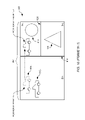
- FIG. 9 illustrates an integrated acceleration data structure 900 , according to one embodiment of the invention.
- the exemplary integrated acceleration data structure 900 corresponds to the three-dimensional scene 605 illustrated in FIG. 6 .
- the integrated acceleration data structure 900 illustrated in FIG. 9 has an initial structure defined by the spatial index 800 which was described with reference to FIG. 8 , having a world node and smaller bounding volumes.
- the nodes which define bounding volumes within the three-dimensional scene may branch to (i.e., contain information which points to) nodes which define objects located within bounding volumes.
- the final spatially oriented nodes in an integrated acceleration data structure 900 may branch to object nodes which define objects.
- node 855 corresponding to BV 2 may branch to object nodes 760 and 770 (representing the first car object 610 1 and the second car object 610 2 ) from the scene graph 700 .
- the object nodes 760 and 770 are branched to from the node 855 corresponding to BV 2 because the first car object 610 1 and the second car object 610 2 are both located within bounding volume BV 2 as illustrated in FIG. 8 .
- each car object node branches to a wheel object node (e.g., 762 or 772 ) and a body object node (e.g., 764 or 774 ), which further define each car object.
- wheel object node e.g., 762 or 772
- body object node e.g., 764 or 774
- the circle object node 780 is branched to from the node 865 defining the bounding volume BV 4 .
- the circle object node 780 may be branched to from the node 865 defining bounding volume BV 4 , because the circle object 615 is located within bounding volume BV 4 .
- the triangle object node 790 is branched to from the node 870 defining the bounding volume BV 5 .
- the triangle object node 790 may be branched to from the node 865 defining bounding volume BV 5 , because the triangle object 620 is located within bounding volume BV 5 .
- each node within the integrated acceleration data structure may contain an object node flag or bit.
- the object node bit may be a single bit located within the memory space which defines a node within the integrated acceleration data structure 900 . According to one embodiment of the invention, if a node within the spatial index is an object node, the object node bit may be asserted. Furthermore, if a node within the spatial index is not an object node, the object node bit may not be asserted.
- a physics engine 505 performing physics calculations or the image processing system performing ray tracing may be able to quickly determine if the node is an object node or a node defining a bounding volume by determining if the object node bit is asserted.
- an image processing system may perform ray tracing with an integrated acceleration data structure.
- a spatial index e.g., a kd-tree
- the image processing system may use a workload manager 205 to issue rays into the three-dimensional scene and to trace the rays (based on the trajectory of the ray) through the three-dimensional scene.
- the workload manager 205 may trace rays through the three-dimensional scene using the spatial index by performing ray-bounding volume intersection tests against the bounding volumes defined by the nodes in the spatial index.
- the workload manager 205 may take branches to nodes based on which bounding volumes are intersected by the ray.
- the workload manager 205 may send the ray to a vector throughput engine 210 to determine if the ray intersects any primitives (e.g., contained within the bounding volume defined by the leaf node). If the ray intersects a primitive, the vector throughput engine 210 may consequently determine the color contribution to the two-dimensional image based on an intersected primitive. If not, the workload manager 205 may traverse the kd-tree again to determine if the ray intersects any other primitives located within the three-dimensional scene.
- a vector throughput engine 210 may determine if the ray intersects any primitives (e.g., contained within the bounding volume defined by the leaf node). If the ray intersects a primitive, the vector throughput engine 210 may consequently determine the color contribution to the two-dimensional image based on an intersected primitive. If not, the workload manager 205 may traverse the kd-tree again to determine if the ray intersects any other primitives located within the three-dimensional scene.
- the image processing system may use an integrated acceleration data structure 900 to perform ray tracing, in a manner similar to using a spatial index.
- the image processing system may issue rays into the three-dimensional scene and trace rays through the three-dimensional scene using the integrated acceleration data structure 900 by performing ray-bounding volume intersection tests against the bounding volumes defined by the spatially oriented nodes in the spatial index.
- the workload manager 205 may take branches to nodes based on which bounding volumes are intersected by the ray. When the workload manager 205 traverses to a certain point within the integrated acceleration data structure (e.g., an object node), the workload manager 205 may send the ray to a vector throughput engine 210 to determine if the ray intersects any primitives. However, according to other embodiments of the invention, the workload manager 205 may determine if the ray intersects any primitives.
- the physics engine 505 may perform physics related tasks using the integrated acceleration data structure.
- the physics engine may determine the effect of physical phenomena on objects within the three-dimensional scene 605 on an object-by-object basis.
- the physics engine 505 may perform the same physics calculations with an integrated acceleration structure on an object-by-object basis by searching for object nodes within the integrated acceleration data structure 900 .
- the physics engine 505 may determine if a node is an object node by checking the object node bit in the information which defines the node. Once a node is found within the integrated acceleration data structure that has its object node bit asserted, the physics engine may perform physics calculations on the object.
- a single data structure may be formed which may be used by both the image processing system and the physics engine 505 .
- each entire object may be contained within a single bounding volume
- portions of objects may be located within two separate bounding volumes. That is, objects within the three-dimensional scene may be divided by a splitting plane which creates a boundary between bounding volumes. Consequently, portions of an object may be located within separate bounding volumes created by the splitting plane.
- the information defining an object node may contain a bit location which indicates that information which defines the entire object is located within a plurality of object nodes within the integrated acceleration data structure.
- the bit within the information defining an object node may be asserted to indicate that information which defines the object may be located within a plurality of object nodes of the integrated acceleration data structure, and de-asserted to indicate that the information which defines the object is located entirely within the current object node.
- a pointer to another object node (or nodes) which contain the remaining information which defines the object may be stored in each object node (which contains a portion of the object, according to one embodiment of the invention.
- the physics engine may quickly find the other object node(s) within the integrated acceleration data structure.
- the likelihood may be reduced that a physics engine 505 performing position updates or collision detection tests fails to perform tests against all of the portions of an object located within the three-dimensional scene.
- an integrated acceleration data structure 900 may be used to maintain a record of movements or changes to objects located within the three-dimensional scene.
- FIG. 10 illustrates a three-dimensional scene 605 B where the first car object 610 1 has moved from a first position in the frame N of the three-dimensional scene 605 to a second position in frame N+1 of the three-dimensional scene 605 (as illustrated by the dashed lines in FIG. 10 ).
- hardware or software components within the image processing system may update the integrated acceleration data structure 900 .
- the physics engine 505 may update the integrated acceleration data structure 900 to reflect change in position or shape of objects within the three-dimensional scene 605 .
- the physics engine 505 may perform position updates and collision detection tests for all of the objects located within the three-dimensional scene. For example, the object node 760 corresponding to the first car object 610 , may be updated to reflect the new position of the first car object 610 1 . After performing the tests, the physics engine 505 may record the results of the calculations (e.g., the new positions of the objects) in the integrated acceleration data structure 900 .
- the physics engine 505 may update the branches as well. For example, the movement of the first car object 610 1 from its position illustrated in frame N of the three-dimensional scene 605 (as seen in FIG. 7 ) to its position illustrated in frame N+1 of the three-dimensional scene (as seen in FIG. 10 ) may require that the physics engine 505 update the position of the first car object 610 1 in the integrated acceleration data structure 900 . Furthermore, as illustrated in FIG. 10 the first car object has moved to such a degree that it is no longer located within the bounding volume BV 2 , rather the first car object 610 1 has moved such that it is located within the bounding volume BV 4 . Thus, the physics engine 505 may update the integrated acceleration data structure 900 so that the node 865 corresponding to BV 4 branches to the object node 760 corresponding to the first car object 610 .
- FIG. 11 illustrates an updated integrated acceleration data structure 900 B which reflects the new position of the first car object 610 1 .
- the branch from the node 855 corresponding to BV 2 to the object node 760 corresponding to the first car object 610 1 may have been removed or deleted by the physics engine 505 to reflect the movement of the first car object 610 1 out of the bounding volume BV 2 .
- a new branch from the spatial index node 865 corresponding to BV 4 to the object node 760 corresponding to the first car object 610 1 may have been added by the physics engine 505 to reflect the movement of the first car object 610 1 into the bounding volume BV 4 .
- the new position of the first car object 610 1 in the three-dimensional scene 605 is now reflected in the updated integrated acceleration data structure 900 B.
- the remaining nodes and branches in the updated integrated acceleration data structure 900 B are the same as in the integrated acceleration data structure 900 because (in this simple example) no other objects moved from frame N to frame N+1.
- the image processing system may now use the updated integrated acceleration data structure 900 B to render a two-dimensional image from the three-dimensional scene 605 , and the physics engine 505 may use the updated integrated acceleration data structure 900 B to perform physics related calculations.
- ray-tracing image processing may be used in conjunction with a physics engine to provide animation.
- ray-tracing image processing may be used in conjunction with a physics engine (e.g., in a game system) to simulate and display the physical behavior of objects within a three-dimensional scene.
- Objects within the three-dimensional scene may be considered either dynamic objects or static objects.
- Dynamic objects may be moved or changed by a physics engine over time, while static objects may stay in the same shape or position within the three-dimensional scene over time.
- the physics engine may move dynamic objects within the three-dimensional scene and a ray-tracing image processing system may render a frame (two-dimensional image) which illustrates the objects in the three-dimensional scene.
- the moving of objects and rendering of the three-dimensional scene may occur many times per second (e.g., 30-60 times per second) in order to provide realistic animation.
- a spatial index (e.g., an acceleration data structure) may be used in image processing systems to accelerate ray-tracing image processing.
- An efficient spatial index which accurately partitions the three-dimensional scene according to the positions of objects within the scene may take a relatively long amount of time to construct. Therefore, it may not be efficient to rebuild or recreate a spatial index each time an object moves within the three-dimensional scene (e.g., a dynamic object).
- one technique to manage a three-dimensional scene containing different types of objects i.e., static and dynamic objects
- one acceleration data structure may partition the three-dimensional scene with respect to the dynamic objects
- another acceleration data structure may partition the three-dimensional scene with respect to static objects.
- only the dynamic spatial index may need to be rebuilt in response to the movement of dynamic objects within the scene.
- this technique may require casting and tracing twice the number of rays (i.e., a first set of rays cast into the static acceleration data structure and a second set of rays cast into the dynamic acceleration data stricture).
- Increasing rays may increase the workload experienced by the image processing system and may increase the time required to render the scene thereby offsetting some of the gains in efficiency achieved by using the two spatial indexes. Therefore, two spatial indexes may not be desirable in an image processing system when used in conjunction with other systems to provide animation.
- a single spatial index may be built which partitions the three-dimensional scene with respect to both static and dynamic objects.
- the image processing system may create separate spatial indexes for static and dynamic objects. Furthermore, the image processing system may link the static spatial index to the dynamic spatial index (or indexes) in order to create a combined spatial index.
- the final combined spatial index (combined acceleration data structure) may then be used by the image processing system to perform ray-tracing. Consequently, the image processing system may only need to issue a single set of rays through the combined acceleration data structure.
- the portions of the combined spatial index which reflect the positions of the dynamic objects may be easily modified to reflect new positions of the dynamic objects.
- FIG. 12 illustrates an exemplary three-dimensional scene 1200 containing both static and dynamic objects.
- the static objects within the three-dimensional scene 1200 are the first car object 610 1 , the second car object 610 2 , the circle object 615 , and the triangle object 620 .
- the three-dimensional scene 1200 also contains a dynamic bicycle object 1205 .
- the three-dimensional scene 1200 is the same as the three-dimensional scene 1200 illustrated in FIG. 6 , and therefore may be partitioned in a similar fashion (e.g., using partitioning planes 815 and 820 ) resulting in a similar bounding volumes (e.g., BV 1 -BV 5 ).
- an image processing system may create a combined spatial index which partitions the three-dimensional scene with respect to the positions of both the dynamic objects and the static objects within the three-dimensional scene.
- FIG. 13 is a flowchart which illustrates an exemplary method 1300 for creating a combined spatial index.
- the method 1300 may begin at step 1305 where the image processing system may create a spatial index based on the static objects within a three-dimensional scene (static spatial index). For example, based on the static objects (i.e., the first car object 610 1 , the second car object 610 2 , the circle object 615 , and the triangle object 620 ) within the three-dimensional scene 1200 , the image processing system may create static spatial index 1400 illustrated in FIG. 14 .
- the static spatial index 1400 may be similar to the integrated acceleration data structure 900 illustrated in FIG. 9 which was created based on the three-dimensional scene 605 .
- the static spatial index 1400 is illustrated as an integrated acceleration data structure in FIG. 14 , other embodiments of the invention may create a different type of spatial index for the static objects (e.g., a kd-tree).
- the image processing system may create a dynamic object bounding volume (hereinafter DOBV) for a dynamic object within the three-dimensional scene.
- DOBV may be created such that it completely surrounds the dynamic object.
- multiple splitting planes may be drawn to create a volume which totally surrounds the dynamic bicycle object 1205 .
- FIG. 15 illustrates a DOBV BV A created for the dynamic bicycle object 1205 .
- the image processing system may create a dynamic object spatial index.
- the dynamic object spatial index may be created by partitioning the DOBV into smaller bounding volumes. This process may be similar to the spatial index creation process described above with respect to FIGS. 4A-4C .
- the nodes of the resulting dynamic object spatial index may contain information which defines the DOBV and bounding volumes which partition the DOBV (e.g., the splitting axes along which the splitting planes are drawn and the location of the splitting plane along the splitting plane axes).
- the bounding volume BV A which surrounds the dynamic bicycle object 1205 may be partitioned by drawing splitting planes (e.g., axis-aligned splitting plane 1550 and axis-aligned splitting plane 1555 ) to create several bounding volumes (e.g., BV B -BV E ).
- the bounding volumes (BV A -BV E ) may be defined by nodes (e.g., nodes 1505 - 1525 ) in a corresponding dynamic object spatial index 1500 .
- the image processing system may box trace the DOBV through the static spatial index which was created based on the static objects within the three-dimensional scene.
- the DOBV BV A which surrounds the dynamic bicycle object 1205 may be box traced through the static spatial index 1400 created in step 1305 .
- Box tracing may be (roughly) defined as traversing a bounding volume through a spatial index (in a similar manner as traversing the spatial index with a ray cast into the scene). This may include testing the location and dimensions of a bounding volume (e.g., a box) against bounding volumes defined by the nodes of a spatial index to determine if a portion of the box intersects, or is within, the bounding volumes defined by the nodes.
- a bounding volume e.g., a box
- the image processing system may determine which bounding volumes of the static spatial index the DOBV exists within.
- FIG. 16 illustrates the dynamic bicycle object 1205 in the three-dimensional scene 1200 and surrounded by the DOBV BV A .
- the DOBV BV A exists within both bounding volume BV 2 and bounding volume BV 3 . Therefore, box tracing DOBV BV A through the static spatial index 900 which partitions the three-dimensional scene 1200 should indicate that the DOBV BV A exists within both bounding volume BV 2 and bounding volume BV 3 .
- FIG. 17 illustrates the traversal of the DOBV BV A through the static spatial index 1400 .
- the image processing system may begin box tracing or traversing the DOBV BV A through the static spatial index 1400 by determining if the DOBV BV A is within or intersects the bounding volume defined by the world node 850 (i.e., BV 1 ).
- the DOBV is within the bounding volume defined by the world node 850 (i.e., BV 1 ), and therefore the results of the image processing system's intersection tests will indicate the intersection.
- Intersection of the DOBV BV A with a bounding volume defined by nodes (e.g., world node 850 ) in the static spatial index 1400 is illustrated in FIG. 17 by the darkened outline of the nodes (e.g., the darkened outline of the world node 850 ).
- the image processing system may continue to traverse static spatial index 1400 by performing intersection tests to determine if the DOBV BV A intersects or is within the bounding volumes defined by the nodes beneath the world node 850 (i.e., BV 2 and BV 3 ).
- the image processing system may determine from these tests that the DOBV BV A is within or intersects the bounding volumes defined by the nodes beneath the world node 850 (i.e., the DOBV BV A intersects both BV 2 and BV 3 ).
- the image processing system may then continue traversing the static spatial index 1400 by taking the branches from the world node 850 to the nodes beneath the world node 850 .
- the image processing system may continue traversing or box tracing through the static spatial index 1400 until leaf nodes are reached.
- a leaf node of the static spatial index may be a node which defines a bounding volume within the three-dimensional scene which is not further partitioned by a splitting plane.
- the image processing system may take a branch from node 850 (defining bounding volume BV 1 ) to node 855 (defining bounding volume BV 2 ). Because node 855 is a leaf node, the image processing system may add leaf node 855 to a list of traversed-to leaf nodes to be used later in method 1300 .
- the image processing system may also take the branch from node 850 (defining bounding volume BV 1 ) to the node 860 .
- Node 860 is an internal node thus the image processing system may perform intersection tests with the nodes beneath node 860 (i.e., node 865 and node 870 ) to determine if the DOBV BV A is within or intersects the bounding volumes defined by the nodes beneath node 860 (i.e., BV 4 and BV 5 ). As can be see in FIG. 16 , a portion of the DOBV BV A is within BV 5 but no portion of DOBV BV A is within BV 4 . Therefore, the image processing system may take the branch to node 870 as illustrated by the darkened outline of node 870 in FIG.
- FIG. 17 The intersection with BV 5 and not BV 4 is illustrated in FIG. 17 by the darkened outline of node 870 which corresponds to BV 5 , but no darkened outline of node 865 corresponding to BV 4 . Furthermore, because BV 5 is a leaf node the image processing system may add the leaf node 807 which defines BV 5 to the list of leaf nodes traversed-to while traversing DOBV BV A through the static spatial index 1400 .
- the image processing system may create links from the traversed-to leaf nodes of the static spatial index 1400 (indicated in the list of traversed-to leaf nodes) to the world node of the dynamic object spatial index which was created for the dynamic object in step 1315 .
- the image processing system may create a link from node 855 (corresponding to BV 2 ) to the world node 1505 of the dynamic object spatial index 1500 , and a link from node 870 (corresponding to BV 5 ) to the world node 1505 of the dynamic object spatial index 1500 .
- the image processing system By creating links from the static spatial index 1400 to the dynamic object spatial index 1500 , the image processing system creates a single combined spatial index 1800 or combined acceleration data structure which is partitioned according to the positions of both static objects and dynamic objects within the three-dimensional scene.
- the image processing system may trace a ray through the combine spatial index to a leaf node of the spatial index (e.g., node 870 ) which branches to the world node 1505 of the dynamic object spatial index 1500 portion of the combine spatial index 1800 .
- the image processing system may then perform ray-bounding volume intersection tests with the bounding volume defined by the world node of the dynamic object spatial index to determine if the ray intersects the DOBV.
- the image processing system may begin traversing the ray through the dynamic object spatial index 1500 portion of the combine spatial index 1800 . Therefore, when using a combine spatial index the image processing system may only need to traverse rays issued into the three-dimensional scene through the combined spatial index 1800 to determine if the ray intersects static objects or dynamic objects within the three-dimensional scene. Therefore, in contrast to having two separate spatial indexes for static objects and dynamic objects, by having a single combine spatial index fewer rays may need to be traversed through spatial indexes to determine if the ray intersects objects within the three-dimensional scene.
- the image processing system may remove the links between static and dynamic spatial indexes which were created for a previous frame. Further, the image processing system may create new links corresponding to the new position of the dynamic objects, for example, by repeating steps 1320 and 1325 of method 1300 .
- multiple dynamic objects may be represented in the combined spatial index by creating multiple dynamic objects spatial indexes which correspond to multiple dynamic objects within the three-dimensional scene and linking the static spatial index to each of the dynamic object spatial indexes.
- the image processing system may have to perform an unnecessary number of ray-bounding volume intersection tests when using the combined spatial index 1800 .
- a ray may intersect the bounding volume BV 5 but not the bounding volume BV 2 .
- the ray may intersect the DOBV BV A .
- the image processing system may traverse the ray to node 870 of combined spatial index 1800 (i.e., because the ray intersects the bounding volume BV 5 ), but not to node 855 (i.e., because the ray does not intersect the bounding volume BV 2 ).
- the image processing system using the combined spatial index 1800 may perform ray-bounding volume intersection tests with nodes 1505 , 1510 , 1515 , 1520 and 1525 of the of the dynamic object spatial index portion 1500 of the combined spatial index 1800 .
- ray-bounding volume intersection tests may be unnecessary since the bounding volumes defined by nodes 1510 and 1520 (i.e., BV B and BV D ) do not exist within BV 5 , and therefore there is no way the ray will intersect these bounding volumes (i.e., BV B and BV D ). Consequently, by merely linking the leaf nodes of the static spatial index 1400 to the world node of the dynamic spatial index 1500 , the image processing system may introduce an unnecessary burden or load (in terms of ray-bounding volume intersection tests) when performing ray-tracing.
- the image processing system may reduce the number of ray-bounding volume intersection tests by performing deep placement of the dynamic object within the static spatial index.
- deep dynamic object placement may link the leaf nodes of the static spatial index to specific portions of the dynamic object spatial index in order to reduce the number of ray-bounding volume intersection tests necessary to perform ray tracing with a combined spatial index.
- FIG. 19 is a flowchart which illustrates a method 1900 of performing deep dynamic object placement, according to one embodiment of the invention.
- the first four steps of the method 1900 are the same as the first four steps of method 1300 .
- Those steps include creating a static spatial index based on the static objects within the three-dimensional scene (step 1305 ), creating a DOBV which surrounds a dynamic object (step 1310 ), creating a dynamic object spatial index by partitioning the DOBV (step 1315 ), and box tracing the DOBV through the static spatial index and creating a list of leaf nodes in the static spatial index which were traversed to (step 1320 ).
- the image processing system may proceed to step 1905 .
- the image processing system may box trace the bounding volumes defined by the traversed-to leaf nodes of the static spatial index through the dynamic object spatial index.
- the image processing system may determine which bounding volumes defined by nodes of the dynamic object spatial index exist within or intersect/overlap the bounding volumes defined by the traversed-to leaf nodes of the static spatial index.
- the image processing system may have box traced the DOBV BV A which surrounds the dynamic bicycle object 1200 through the static spatial index 1400 .
- the image processing system may have determined that the DOBV BV A intersected or existed within two bounding volumes (i.e., BV 2 and BV 5 ) defined by two leaf nodes (i.e., node 855 and node 870 ) of the static spatial index 1400 . Therefore, at step 1905 of method 1900 the image processing system may box trace the bounding volumes (i.e., BV 2 and BV 5 ) defined by the traversed-to leaf nodes of the static spatial index (i.e., node 855 and node 870 ) through the dynamic object spatial index 1500 .
- Box tracing may be (roughly) defined as traversing a bounding volume through a spatial index. This may entail testing the location and dimensions of a box (e.g., a bounding volume) against bounding volumes defined by the nodes of the static spatial index to determine if a portion of the box intersects or is within a bounding volume defined by a node of the spatial index.
- the image processing system may begin traversing the box static spatial index at the world node, and may take branches to nodes intersected by the box.
- FIG. 20 illustrates the image processing system traversing the bounding volume BV 2 through the dynamic object spatial index 1500 .
- the dynamic object spatial index 1500 bounding volumes which are intersected by the bounding volume BV 2 are illustrated in FIG. 20 by darkened outlines (i.e., nodes 1505 , 1510 , 1515 , and 1520 ).
- the image processing system traverses or box traces the bounding volume BV 2 to two leaf nodes of the dynamic objects spatial index. Specifically, leaf node 1510 and leaf node 1520 which define bounding volumes BV B and BV D , respectively.
- the image processing system has determined that the bounding volumes (BV B and BV D ) defined by leaf node 1510 and leaf node 1520 are within bounding volume BV 2 .
- the bounding volumes defined by the two nodes i.e., BV B and BV D ) may be added to a list of traversed-to leaf nodes which may be used later by the method 1900 .
- FIG. 21 illustrates the image processing system box tracing the bounding volume BV 5 through the dynamic object spatial index 1500 .
- the dynamic object spatial index 1500 bounding volumes which are intersected by the traversed-to leaf node bounding volume BV 5 are illustrated in FIG. 21 by darkened outlines (i.e., nodes 1505 , 1515 , and 1525 ).
- the image processing system traverses or box traces BV 5 to a single leaf node of the dynamic objects spatial index 1500 . Specifically, leaf node 1525 which defines bounding volume BV E .
- the image processing system has determined that the bounding volume (BV E ) defined by leaf node 1525 is within BV 5 .
- the bounding volume (BV E ) defined by leaf node 1525 may be added to a list of traversed-to leaf nodes which may be used later by the method 1900 .
- the image processing system may link the traversed-to leaf nodes of the static spatial index to their respectively traversed-to leaf nodes of the dynamic spatial index (e.g., as stored in the respective lists of traversed-to leaf nodes).
- the image processing system may deeply place the dynamic object within a single combined spatial index.
- FIG. 22 illustrates a combined spatial index 2200 wherein the dynamic bicycle object 1205 has been deeply placed into the combined spatial index 2200 .
- the image processing system may create links or branches from node 855 (defining bounding volume BV 2 ) based on the list of traversed-to leaf nodes which was created in step 1905 when the image processing system traversed BV 2 though the dynamic object spatial index 1500 .
- the image processing system may create a link or a branch from node 855 (defining bounding volume BV 2 ) to the leaf node 1510 (defining bounding volume BV B ), and a link or a branch from node 855 (defining bounding volume BV 2 ) to the leaf node 1520 (defining bounding volume BV D ).
- the image processing system may also create links or branches from node 870 (defining bounding volume BV 5 ) based on the list of traversed-to leaf nodes which was created in step 1905 when the image processing system traversed bounding volume BV 5 though the dynamic object spatial index 1500 . Accordingly, the image processing system may create a link or a branch from node 870 (defining bounding volume BV 5 ) to the leaf node 1525 (defining bounding volume BV E ).
- the image processing system may deeply place the dynamic object within the combined spatial index 2200 . Thereafter the image processing system may use the combined spatial index 2200 to accelerate ray-tracing image processing.
- the image processing system may perform ray-bounding volume intersection tests with the bounding volume defined by the leaf node BV E as well as intersection tests with the triangle object.
- the image processing system may reduce the number of ray-bounding volume intersection which are necessary when a ray intersects the bounding volume BV E tests by performing a ray-bounding volume intersection test only with bounding volume BV E and not with the other bounding volumes defined by the nodes within the dynamic spatial index portion 1500 of the combined spatial index 2200 .
- embodiments of the invention are described above as linking leaf nodes of the static spatial index to the world node or leaf nodes of the dynamic spatial index, other embodiments of the invention are contemplated which may link different nodes of the static spatial index (e.g., internal nodes, etc.) to different nodes of the dynamic spatial index (e.g., internal nodes, etc.).
- dynamic objects within the three-dimensional scene may have unique spatial indexes (e.g., dynamic object spatial indexes) created when partitioning a bounding volume which surrounds the dynamic objects.
- the dynamic object may have its own coordinate system.
- a coordinate system unique to a dynamic object hereinafter an object coordinate system
- an object coordinate system may have an origin located at the center of the dynamic object.
- an object coordinate system may have unique coordinate system axes which may or may not be parallel to the global coordinate system axes.
- a dynamic object may be constructed from a plurality of primitives (e.g., triangles, spheres, boxes, etc.).
- the dynamic object may be defined by a set of variables describing the object including, but not limited to, a dynamic object center (e.g., the origin of the object coordinate system) and a rotation of the object (or the object coordinate system) relative to the world coordinate system.
- the primitives which make up the dynamic object may be defined relative to the origin of the object coordinate system and may be defined without a rotational factor.
- the center and rotation of the dynamic object may be added to the coordinates of the primitive in the object coordinate system.
- Updates to the position and/or rotation of the entire dynamic object may be accomplished by simply modifying the center of the object coordinate system and the rotation of the object coordinate system. Consequently, it may not be necessary to modify each individual primitive which makes up the dynamic object in order to modify the position or rotation of the dynamic object.
- An object may also have a unique object coordinate system due to the loss of accuracy when specifying the location or coordinates of primitives which make up the object when the object is some distance away from the origin of the three-dimensional scene.
- the loss of accuracy may be attributed to the use of floating point numbers to specify the location of points within the three-dimensional scene.
- Many image processing systems use floating point numbers to specify the location of points within the three-dimensional scene. In an image processing system which uses floating point numbers, the farther a point from the origin of a coordinate system, the less accurate the coordinates are at specifying a location of a point. In contrast, the closer a point may be the origin of the coordinate system, the more accurate the coordinate system may be at specifying the location of the point. Therefore, if an object is located some distance from the world origin and an object coordinate system with an origin located at the center of a dynamic object is used, the object coordinate system may be more accurate at specifying the location of points which define the object than the world coordinate system.
- FIG. 23 illustrates a three-dimensional scene 2300 similar to the three-dimensional scene 1200 described above with regards to FIG. 16 .
- the circle object 615 has been removed from three-dimensional scene 2300
- the dynamic bicycle object 1205 has been moved to a location within the bounding volume BV 4 .
- the image processing system or some other system responsible for tracking the movements of objects within the three-dimensional scene (e.g., the physics engine)
- the object coordinate system may have an origin located in the center of the dynamic object (e.g., the center of the bicycle object 1205 ).
- the object coordinate system may be located some distance from the world coordinate system. For example, as illustrated in FIG.
- the origin of the object coordinate system may be located a distance d 1 from the origin of the world coordinate system.
- the object coordinate system may have axes (e.g., x-axis, y-axis, and z-axis) which are aligned with the axes of the world coordinate system.
- the location of the primitives which make up the dynamic bicycle object 1205 may be defined relative to the object coordinate system (i.e., in coordinates of the object coordinate system).
- a bounding volume (e.g., BV A ) may be created which surrounds or bounds the dynamic object.
- the bounding volume surrounding the dynamic bicycle object (BV A ) may be partitioned, as described above with respect to FIG. 15 , and the corresponding dynamic object spatial index 1500 may be linked to from a leaf node (e.g., leaf node 865 ) corresponding to the bounding volume (i.e., BV 4 ) within which the bicycle object 1205 is located.
- a combined spatial index 2400 may be formed from the static spatial index 1400 and the dynamic object spatial index 1500 .
- information which defines the object coordinate system may be stored within the dynamic object spatial index portion 1500 of the combined spatial index 2400 .
- the node 1505 corresponding to the bounding volume which surrounds the dynamic bicycle object 1205 i.e., BV A
- the location e.g., in world coordinates
- the dynamic object may be rotated by the physics engine. Consequently, the axes of the object coordinate system may be rotated with respect to the world coordinate system.
- the bicycle object 1205 and the object coordinate system axes may be rotated in a clockwise direction with respect to the world coordinate system.
- the rotation of the object and the object coordinate system may be stored in the dynamic object portion 1500 of the spatial index 2400 .
- the rotation and the location of the object coordinate system in world coordinates may be used to transform the coordinates of primitives in the object coordinate system into coordinates in the world coordinate system.
- an image processing system may issue a ray 2600 into a three-dimensional scene 2500 which contains the rotated dynamic bicycle object 1205 .
- the three-dimensional scene 2500 is the same as described above with respect to FIG. 25 and, therefore, may be represented by the combined spatial index 2400 illustrated in FIG. 24 .
- the ray 2600 may be issued from a view point 2605 and may have a trajectory such that it intersects the bounding volume (BV A ) which bounds the dynamic bicycle object 1205 .
- BV A bounding volume
- the image processing system may perform ray intersection tests (e.g., ray-bounding volume intersection tests and ray-primitive intersection tests) using one of two different techniques.
- One technique may be to translate or convert the location of or coordinates of primitives which make up the dynamic object (e.g., the coordinates of vertexes which form a triangle primitive) from the object coordinate system into coordinates in the world coordinate system.
- the image processing system may store the converted coordinates in the combined spatial index.
- the image processing system may perform intersection tests with the rays in the world coordinate system. Consequently, the image processing system may trace rays through the entire spatial index without having to change coordinate systems when performing ray-intersection tests. This may reduce the amount of time required to perform ray tracing, however, this may increase the amount of time to build or prepare the spatial index for ray tracing.
- the amount of processing workload e.g., processing cycles
- the amount of processing workload associated with executing ray intersection tests with the dynamic object must exceed the amount of processing workload required to convert the location of primitives which define the dynamic object from the object coordinate system into the world coordinate system. As described further below, this may occur when a large number of rays are likely to intersect the dynamic object when performing ray tracing.
- FIG. 27 illustrates the first technique. As illustrated in FIG. 27 , the dynamic bicycle object 1205 remains rotated with respect to the world coordinate system, however the coordinates of the primitives which define the dynamic bicycle object 1205 may have been translated from the object coordinate system into the world coordinate system and stored in the combined spatial index. Additionally, FIG. 27 illustrates the trajectory of the ray remains in the world coordinate system when using the first technique.
- a second technique of performing ray intersection tests may be to translate the trajectory of rays which are traversed to the dynamic object portion of the combined spatial index from trajectories in the world coordinate system into trajectories in the object coordinate system, and perform ray intersection tests in the object coordinate system.
- the trajectories of a ray may be translated into the object coordinate system using the origin of the object coordinate system and the rotation of the object.
- the processing workload required to convert the location of primitives which define the dynamic object from the object coordinate system to the world coordinate system must exceed the amount of processing workload associated with executing ray intersection tests in the object coordinate system. As described further below, this may occur when a small number of rays are likely to intersect the dynamic object when performing ray tracing.
- FIG. 28 illustrates the second technique.
- the trajectory of a ray may be translated into the object coordinate system when a ray is traversed to the dynamic object portion of the spatial index. Additionally, FIG. 28 illustrates the object remains in the object coordinate system when using the second technique.
- either the first technique or the second technique may be more efficient to use when performing ray tracing.
- FIG. 29 is a flowchart illustrating an exemplary method 2900 of creating a combined spatial index which contains an object with an object coordinate system, according to embodiments of the invention.
- the method may begin at step 2905 when a system responsible for creating the spatial index (e.g., the image processing system or the physics engine) constructs a spatial index by partitioning a three-dimensional scene.
- a system responsible for creating the spatial index e.g., the image processing system or the physics engine
- the image processing system may construct the combined spatial index 2400 illustrated in FIG. 24 by partitioning the three-dimensional scene 2500 containing the dynamic bicycle object 1205 illustrated in FIG. 25 .
- the image processing system may determine a coordinate system to use when performing ray tracing through the dynamic object portion of the spatial index.
- the determination may be based on many factors and thresholds intended to select the most efficient technique to use when performing ray tracing through the dynamic object portion of the spatial index. For example, as described further below with respect to FIG.
- the determination may be based on (but not limited to) a distance from a viewpoint to the origin of the object coordinate system, a distance from an origin of the world coordinate system to the origin of the object coordinate system, a rate of traversal of the dynamic object, a number of primitives which make up the dynamic object, a size of the dynamic object, an amount of memory available, and/or a number of ray-object intersections
- the image processing system may proceed to step 2915 to convert the coordinates of primitives which make up the dynamic object from object coordinates into world coordinates. As described above, this may be accomplished using the amount of rotation the object is rotated with respect to the world coordinate system and the location of the origin of the object coordinate system in the world coordinate system.
- the image processing system may store the converted coordinates in the dynamic object portion of the spatial index. After converting the coordinates of primitives which make up the dynamic object to world coordinates, the image processing system may proceed to step 2925 where the image processing system may being to perform ray tracing for a frame.
- the image processing system may proceed to step 2920 .
- the image processing system may set a bit in the spatial index which may indicate that the dynamic object portion of the spatial index contains information in the object coordinate system.
- This bit may be referred to as the coordinate system bit and may be stored within the spatial index.
- the coordinate system bit may be stored within the node 1505 corresponding to the bounding volume surrounding the dynamic bicycle object 1205 (i.e., BV A ).
- the image processing system may be alerted (via a check of the coordinate system bit) that the trajectory of the ray must be converted into the object coordinate system in order to perform ray intersection tests.
- the image processing system may proceed to step 2925 to begin performing ray tracing for a frame.
- FIG. 30 is a flowchart which illustrates an exemplary method 3000 of determining which coordinate system to use when performing ray tracing through a dynamic object portion of a spatial index, according to one embodiment of the invention.
- the method beings at step 3005 , for example, when step 2910 of method 2900 is executed.
- a determination may be made whether a distance from a viewpoint to the dynamic object exceeds a threshold.
- the distance from the viewpoint to the dynamic object may be important in determining which coordinate system to use when tracing a ray thorough the dynamic object portion of the spatial index, because a dynamic object which is closer to the viewpoint may be intersected by more rays than an object which is further from the viewpoint. If the dynamic object is intersected by a large number of rays it may be more efficient to convert the points which define the object into the world coordinate system, because there may be fewer calculations to convert the entire object into the world coordinate system than to convert each ray which intersects the bounding volume which surrounds the dynamic object into the object coordinate system.
- a dynamic object which is further from the viewpoint may be intersected by a smaller number of rays, and thus fewer ray-trajectory transformations may be necessary when performing ray tracing. If fewer ray trajectory coordinate transformations are needed than the number of calculations which are required to convert the dynamic object to the world coordinate system, it may be more efficient to leave the primitives which make up the object in the object coordinate system and convert the trajectory of rays which are traversed to the dynamic object portion of the combined spatial index into the object coordinate system.
- the threshold distance from the viewpoint to the object may be selected as the distance where the workload (e.g., processing cycles) required to convert the trajectory of all of the rays which are likely to intersect the bounding volume which surrounds the dynamic object is the same as the workload required to convert the dynamic object into world coordinates. If the distance from the viewpoint to the dynamic object exceeds the threshold distance, the image processing system may proceed to step 3010 to select the object coordinate system. However, if the distance threshold is not exceeded, the image processing system may proceed to step 3015 to determine if other factors indicate that it may be more efficient to use the world coordinate system when rays are traversed through the dynamic object portion of the combined spatial index (i.e., convert the primitives which make up the object into world coordinates).
- the workload e.g., processing cycles
- the image processing system may determine if a distance from the object origin to the world origin exceeds a threshold.
- the image processing system may take into consideration the distance from the object coordinate system origin to the world coordinate system origin because a transformation of primitive coordinates from the object coordinate system to the world coordinate system may result in a loss of accuracy when specifying the position of primitives which make up the dynamic object. If the threshold distance form the world origin to the object origin is exceeded, the image processing system may choose to maintain accuracy over improved efficiency and use the object coordinate system when performing ray intersection tests through the dynamic object portion of the spatial index. Consequently, the image processing system may proceed to step 3020 to select the object coordinate system.
- the image processing system may proceed to step 3020 to determine if other factors indicate that it may be more efficient to use the world coordinate system when rays are traversed to the dynamic object portion of the combined spatial index (i.e., convert the primitives which make up the object into world coordinates).
- the image processing system may determine if the object's rate of traversal exceeds a threshold.
- the rate of the object's movement may be important when determining whether to use the object coordinate system or the world coordinate system because if an object is moving relatively fast, converting the object primitives to the world coordinate system may only be effective for a relatively small period of time. That is, the primitive conversions may only be effective for the period of time the object remains in the same position and with the same rotation. Consequently, a relatively fast moving object may require more conversions from the object coordinate system to the world coordinate system. In contrast, a relatively slow moving object may require fewer conversions into the world coordinate system over the same period of frames. If the object requires a relatively large number of conversions, it may be inefficient to frequently convert the object primitives into the world coordinate system in contrast to converting the trajectory of rays which are traversed through the dynamic object portion of the spatial index.
- the rate of traversal threshold may be set such that if the rate of the object traversal exceeds the threshold, the processing workload (e.g., processing cycles) required to convert the object to the world coordinate system over a period of time outweighs the processing workload saved by not having to convert the rays which are traversed to the dynamic object portion of the spatial index over the same period of time. If the rate of dynamic-object traversal does exceed the threshold, the image processing system may proceed to step 3010 to select the object coordinate system. However, if the object rate of traversal does not exceed the threshold, the image processing system may proceed to step 3025 to determine if other factors indicate that it may be more efficient to use the world coordinate system when rays are traversed through the dynamic object portion of the combined spatial index.
- the processing workload e.g., processing cycles
- the image processing system may determine if the number of primitives which make up the dynamic object exceeds a threshold.
- the number of primitives which makeup the dynamic object may be an important consideration when determining which coordinate system to use because the number of primitives may be directly related to the amount of processing workload required to convert the dynamic object primitives into the world coordinate system. If the dynamic object has a relatively large number of primitives which may have to be converted form the object's coordinate system to the world coordinate system, the image processing system may have to perform a large number of conversions to convert the object into the world coordinate system. The large number of conversions may require a large amount of processing power and, consequently, may be inefficient in comparison to converting ray trajectories into the world coordinate system.
- the image processing system may proceed to step 3010 to select the object coordinate system.
- the object has a relatively small number of primitives (small enough to not exceed the threshold)
- converting the object primitives from the object coordinate system to the world coordinate system may be more efficient than converting each ray which is traversed to the dynamic object portion of the spatial index into the object coordinate system. Therefore, if the object has fewer primitives than the threshold, the image processing system may proceed to step 3030 .
- the threshold number of primitives may be selected such that the workload required to convert the threshold number of primitives to the world coordinate system equals the workload required to convert the number of rays which are likely to intersect an object with the threshold number of primitives.
- the image processing system may determine if the size of the object exceeds a size threshold.
- the size of the dynamic object may be an important consideration when determining which coordinate system to use because the size of the object may have a direct correlation with the number of rays which are likely to intersect the object and, thus, may have to be converted into the object coordinate system if the image processing system maintains the primitive coordinates in the object coordinate system. If the object is relatively large, such that a relatively large number of rays are likely to intersect the object it may be more efficient to convert the object primitives into the world coordinate system. However, if the size of the object is relatively small, it may be more efficient to keep the object primitives in the object coordinate system and only convert rays which are traversed through the dynamic object portion of the spatial index into the object coordinate system.
- the size threshold may be set such that the processor workload required to convert the trajectory of rays which are likely to intersect an object of the threshold size and are traversed to the dynamic object portion of the spatial index is equal to the processing workload required to convert the primitives of the dynamic object into the world coordinates. If the size threshold is exceeded, the image processing system may proceed to step 3035 to select the world coordinates system. However, if the size threshold is not exceeded, the image processing system may proceed to step 3010 to select the object coordinate system.
- embodiments of the invention may determine whether to use the object coordinate system or the world coordinate system based on the amount of available memory and the number of ray-object intersections.
- embodiments of the invention may only require one object attribute or determination to select the world coordinate system to use when performing ray tracing through the dynamic object portion of the spatial index.
- the determination of whether to use the object coordinate system or the world coordinate system may be determined based on the fewer factors than illustrated in the flowchart in FIG. 30 .
- the determination to use the object coordinate system or the world coordinate system may be based on a single factor (e.g., distance of the object from the viewpoint) in contrast to multiple factors.
- an image processing system may determine the most efficient coordinate system to use when traversing rays through the portion of a spatial index corresponding to the dynamic object.
- the image processing system may take into consideration a number of factors including, but not limited to, a distance form a viewpoint to the dynamic object, a distance from the origin of the world coordinate system to the object coordinate system, a rate of traversal of the dynamic object, and a number of primitives which make up the object. These factors alone or together may indicate whether it is more efficient to perform ray intersection tests in an object coordinate system or in a world coordinate system.
- the image processing system may convert the object primitives into world coordinates and store the converted primitives in the spatial index. However, if the image processing system determines that it would be more efficient to use the object coordinate system when performing ray tracing through the dynamic portion of the spatial index, according to embodiments of the invention, the image processing system may set a bit in the dynamic object portion of the spatial index to indicate the coordinate system of the object differs from the world coordinate system.
Abstract
Description
Claims (5)
Priority Applications (1)
| Application Number | Priority Date | Filing Date | Title |
|---|---|---|---|
| US11/737,156 US7773087B2 (en) | 2007-04-19 | 2007-04-19 | Dynamically configuring and selecting multiple ray tracing intersection methods |
Applications Claiming Priority (1)
| Application Number | Priority Date | Filing Date | Title |
|---|---|---|---|
| US11/737,156 US7773087B2 (en) | 2007-04-19 | 2007-04-19 | Dynamically configuring and selecting multiple ray tracing intersection methods |
Publications (2)
| Publication Number | Publication Date |
|---|---|
| US20080259075A1 US20080259075A1 (en) | 2008-10-23 |
| US7773087B2 true US7773087B2 (en) | 2010-08-10 |
Family
ID=39871735
Family Applications (1)
| Application Number | Title | Priority Date | Filing Date |
|---|---|---|---|
| US11/737,156 Active 2029-01-31 US7773087B2 (en) | 2007-04-19 | 2007-04-19 | Dynamically configuring and selecting multiple ray tracing intersection methods |
Country Status (1)
| Country | Link |
|---|---|
| US (1) | US7773087B2 (en) |
Cited By (66)
| Publication number | Priority date | Publication date | Assignee | Title |
|---|---|---|---|---|
| US20090073167A1 (en) * | 2007-09-13 | 2009-03-19 | Jeffrey Douglas Brown | Cooperative Utilization of Spacial Indices Between Application and Rendering Hardware |
| US20130329950A1 (en) * | 2012-06-12 | 2013-12-12 | Electronics And Telecommunications Research Institute | Method and system of tracking object |
| US8818544B2 (en) | 2011-09-13 | 2014-08-26 | Stratasys, Inc. | Solid identification grid engine for calculating support material volumes, and methods of use |
| US20160005210A1 (en) * | 2014-07-07 | 2016-01-07 | Samsung Electronics Co., Ltd. | Rendering system and rendering method thereof |
| US9636872B2 (en) | 2014-03-10 | 2017-05-02 | Stratasys, Inc. | Method for printing three-dimensional parts with part strain orientation |
| US10055880B2 (en) | 2016-12-06 | 2018-08-21 | Activision Publishing, Inc. | Methods and systems to modify a two dimensional facial image to increase dimensional depth and generate a facial image that appears three dimensional |
| US10099140B2 (en) | 2015-10-08 | 2018-10-16 | Activision Publishing, Inc. | System and method for generating personalized messaging campaigns for video game players |
| US10118099B2 (en) | 2014-12-16 | 2018-11-06 | Activision Publishing, Inc. | System and method for transparently styling non-player characters in a multiplayer video game |
| US10137376B2 (en) | 2012-12-31 | 2018-11-27 | Activision Publishing, Inc. | System and method for creating and streaming augmented game sessions |
| US10179289B2 (en) | 2016-06-21 | 2019-01-15 | Activision Publishing, Inc. | System and method for reading graphically-encoded identifiers from physical trading cards through image-based template matching |
| US10213682B2 (en) | 2015-06-15 | 2019-02-26 | Activision Publishing, Inc. | System and method for uniquely identifying physical trading cards and incorporating trading card game items in a video game |
| US10226703B2 (en) | 2016-04-01 | 2019-03-12 | Activision Publishing, Inc. | System and method of generating and providing interactive annotation items based on triggering events in a video game |
| US10226701B2 (en) | 2016-04-29 | 2019-03-12 | Activision Publishing, Inc. | System and method for identifying spawn locations in a video game |
| US10232272B2 (en) | 2015-10-21 | 2019-03-19 | Activision Publishing, Inc. | System and method for replaying video game streams |
| US10245509B2 (en) | 2015-10-21 | 2019-04-02 | Activision Publishing, Inc. | System and method of inferring user interest in different aspects of video game streams |
| US20190122427A1 (en) * | 2016-07-26 | 2019-04-25 | Hewlett-Packard Development Company, L.P. | Indexing voxels for 3d printing |
| US10284454B2 (en) | 2007-11-30 | 2019-05-07 | Activision Publishing, Inc. | Automatic increasing of capacity of a virtual space in a virtual world |
| US10286314B2 (en) | 2015-05-14 | 2019-05-14 | Activision Publishing, Inc. | System and method for providing continuous gameplay in a multiplayer video game through an unbounded gameplay session |
| US10286326B2 (en) | 2014-07-03 | 2019-05-14 | Activision Publishing, Inc. | Soft reservation system and method for multiplayer video games |
| US10315113B2 (en) | 2015-05-14 | 2019-06-11 | Activision Publishing, Inc. | System and method for simulating gameplay of nonplayer characters distributed across networked end user devices |
| US10376793B2 (en) | 2010-02-18 | 2019-08-13 | Activision Publishing, Inc. | Videogame system and method that enables characters to earn virtual fans by completing secondary objectives |
| US10376781B2 (en) | 2015-10-21 | 2019-08-13 | Activision Publishing, Inc. | System and method of generating and distributing video game streams |
| US10421019B2 (en) | 2010-05-12 | 2019-09-24 | Activision Publishing, Inc. | System and method for enabling players to participate in asynchronous, competitive challenges |
| US10463964B2 (en) | 2016-11-17 | 2019-11-05 | Activision Publishing, Inc. | Systems and methods for the real-time generation of in-game, locally accessible heatmaps |
| US10463971B2 (en) | 2017-12-06 | 2019-11-05 | Activision Publishing, Inc. | System and method for validating video gaming data |
| US10471348B2 (en) | 2015-07-24 | 2019-11-12 | Activision Publishing, Inc. | System and method for creating and sharing customized video game weapon configurations in multiplayer video games via one or more social networks |
| US10486068B2 (en) | 2015-05-14 | 2019-11-26 | Activision Publishing, Inc. | System and method for providing dynamically variable maps in a video game |
| US10500498B2 (en) | 2016-11-29 | 2019-12-10 | Activision Publishing, Inc. | System and method for optimizing virtual games |
| US10537809B2 (en) | 2017-12-06 | 2020-01-21 | Activision Publishing, Inc. | System and method for validating video gaming data |
| US10561945B2 (en) | 2017-09-27 | 2020-02-18 | Activision Publishing, Inc. | Methods and systems for incentivizing team cooperation in multiplayer gaming environments |
| US10573065B2 (en) | 2016-07-29 | 2020-02-25 | Activision Publishing, Inc. | Systems and methods for automating the personalization of blendshape rigs based on performance capture data |
| US10596471B2 (en) | 2017-12-22 | 2020-03-24 | Activision Publishing, Inc. | Systems and methods for enabling audience participation in multi-player video game play sessions |
| US10627983B2 (en) | 2007-12-24 | 2020-04-21 | Activision Publishing, Inc. | Generating data for managing encounters in a virtual world environment |
| US10694352B2 (en) | 2015-10-28 | 2020-06-23 | Activision Publishing, Inc. | System and method of using physical objects to control software access |
| US10709981B2 (en) | 2016-11-17 | 2020-07-14 | Activision Publishing, Inc. | Systems and methods for the real-time generation of in-game, locally accessible barrier-aware heatmaps |
| US10765948B2 (en) | 2017-12-22 | 2020-09-08 | Activision Publishing, Inc. | Video game content aggregation, normalization, and publication systems and methods |
| US10818060B2 (en) | 2017-09-05 | 2020-10-27 | Activision Publishing, Inc. | Systems and methods for guiding motion capture actors using a motion reference system |
| US10861079B2 (en) | 2017-02-23 | 2020-12-08 | Activision Publishing, Inc. | Flexible online pre-ordering system for media |
| US10974150B2 (en) | 2017-09-27 | 2021-04-13 | Activision Publishing, Inc. | Methods and systems for improved content customization in multiplayer gaming environments |
| US10981069B2 (en) | 2008-03-07 | 2021-04-20 | Activision Publishing, Inc. | Methods and systems for determining the authenticity of copied objects in a virtual environment |
| US10981051B2 (en) | 2017-12-19 | 2021-04-20 | Activision Publishing, Inc. | Synchronized, fully programmable game controllers |
| US11040286B2 (en) | 2017-09-27 | 2021-06-22 | Activision Publishing, Inc. | Methods and systems for improved content generation in multiplayer gaming environments |
| US11097193B2 (en) | 2019-09-11 | 2021-08-24 | Activision Publishing, Inc. | Methods and systems for increasing player engagement in multiplayer gaming environments |
| US11115712B2 (en) | 2018-12-15 | 2021-09-07 | Activision Publishing, Inc. | Systems and methods for indexing, searching for, and retrieving digital media |
| US11185784B2 (en) | 2015-10-08 | 2021-11-30 | Activision Publishing, Inc. | System and method for generating personalized messaging campaigns for video game players |
| US11192028B2 (en) | 2018-11-19 | 2021-12-07 | Activision Publishing, Inc. | Systems and methods for the real-time customization of video game content based on player data |
| US11263670B2 (en) | 2018-11-19 | 2022-03-01 | Activision Publishing, Inc. | Systems and methods for dynamically modifying video game content based on non-video gaming content being concurrently experienced by a user |
| US11278813B2 (en) | 2017-12-22 | 2022-03-22 | Activision Publishing, Inc. | Systems and methods for enabling audience participation in bonus game play sessions |
| US11305191B2 (en) | 2018-12-20 | 2022-04-19 | Activision Publishing, Inc. | Systems and methods for controlling camera perspectives, movements, and displays of video game gameplay |
| US11344808B2 (en) | 2019-06-28 | 2022-05-31 | Activision Publishing, Inc. | Systems and methods for dynamically generating and modulating music based on gaming events, player profiles and/or player reactions |
| US11351459B2 (en) | 2020-08-18 | 2022-06-07 | Activision Publishing, Inc. | Multiplayer video games with virtual characters having dynamically generated attribute profiles unconstrained by predefined discrete values |
| US11351466B2 (en) | 2014-12-05 | 2022-06-07 | Activision Publishing, Ing. | System and method for customizing a replay of one or more game events in a video game |
| US11423605B2 (en) | 2019-11-01 | 2022-08-23 | Activision Publishing, Inc. | Systems and methods for remastering a game space while maintaining the underlying game simulation |
| US11420122B2 (en) | 2019-12-23 | 2022-08-23 | Activision Publishing, Inc. | Systems and methods for controlling camera perspectives, movements, and displays of video game gameplay |
| US11439904B2 (en) | 2020-11-11 | 2022-09-13 | Activision Publishing, Inc. | Systems and methods for imparting dynamic and realistic movement to player-controlled avatars in video games |
| US11524234B2 (en) | 2020-08-18 | 2022-12-13 | Activision Publishing, Inc. | Multiplayer video games with virtual characters having dynamically modified fields of view |
| US11537209B2 (en) | 2019-12-17 | 2022-12-27 | Activision Publishing, Inc. | Systems and methods for guiding actors using a motion capture reference system |
| US11563774B2 (en) | 2019-12-27 | 2023-01-24 | Activision Publishing, Inc. | Systems and methods for tracking and identifying phishing website authors |
| US11679330B2 (en) | 2018-12-18 | 2023-06-20 | Activision Publishing, Inc. | Systems and methods for generating improved non-player characters |
| US11712627B2 (en) | 2019-11-08 | 2023-08-01 | Activision Publishing, Inc. | System and method for providing conditional access to virtual gaming items |
| US11717753B2 (en) | 2020-09-29 | 2023-08-08 | Activision Publishing, Inc. | Methods and systems for generating modified level of detail visual assets in a video game |
| US11724188B2 (en) | 2020-09-29 | 2023-08-15 | Activision Publishing, Inc. | Methods and systems for selecting a level of detail visual asset during the execution of a video game |
| US11794107B2 (en) | 2020-12-30 | 2023-10-24 | Activision Publishing, Inc. | Systems and methods for improved collision detection in video games |
| US11833423B2 (en) | 2020-09-29 | 2023-12-05 | Activision Publishing, Inc. | Methods and systems for generating level of detail visual assets in a video game |
| US11853439B2 (en) | 2020-12-30 | 2023-12-26 | Activision Publishing, Inc. | Distributed data storage system providing enhanced security |
| US11957984B2 (en) | 2008-03-07 | 2024-04-16 | Activision Publishing, Inc. | Methods and systems for determining the authenticity of modified objects in a virtual environment |
Families Citing this family (22)
| Publication number | Priority date | Publication date | Assignee | Title |
|---|---|---|---|---|
| US7542034B2 (en) * | 2004-09-23 | 2009-06-02 | Conversion Works, Inc. | System and method for processing video images |
| US7782318B2 (en) * | 2006-11-22 | 2010-08-24 | International Business Machines Corporation | Method for reducing network bandwidth by delaying shadow ray generation |
| US8274530B2 (en) | 2007-03-12 | 2012-09-25 | Conversion Works, Inc. | Systems and methods for filling occluded information for 2-D to 3-D conversion |
| KR101004110B1 (en) * | 2009-05-28 | 2010-12-27 | 주식회사 실리콘아츠 | Ray tracing core and ray tracing chip having the same |
| KR101076807B1 (en) * | 2009-05-29 | 2011-10-25 | 주식회사 실리콘아츠 | Ray tracing apparatus and method |
| US20120203806A1 (en) * | 2011-02-07 | 2012-08-09 | Ivan Panushev | Building information management system |
| US9235921B2 (en) | 2011-11-08 | 2016-01-12 | Imagination Technologies Limited | Profiling ray tracing renderers |
| CN103959340A (en) * | 2011-12-07 | 2014-07-30 | 英特尔公司 | Graphics rendering technique for autostereoscopic three dimensional display |
| US10970912B2 (en) | 2013-03-14 | 2021-04-06 | Imagination Technologies Limited | 3-D graphics rendering with implicit geometry |
| GB2549217B (en) * | 2013-03-14 | 2017-11-22 | Imagination Tech Ltd | 3-D Graphics rendering with implicit geometry |
| US8817026B1 (en) | 2014-02-13 | 2014-08-26 | Raycast Systems, Inc. | Computer hardware architecture and data structures for a ray traversal unit to support incoherent ray traversal |
| US9842424B2 (en) * | 2014-02-10 | 2017-12-12 | Pixar | Volume rendering using adaptive buckets |
| US9697640B2 (en) * | 2014-04-21 | 2017-07-04 | Qualcomm Incorporated | Start node determination for tree traversal in ray tracing applications |
| GB2526598B (en) * | 2014-05-29 | 2018-11-28 | Imagination Tech Ltd | Allocation of primitives to primitive blocks |
| US9552664B2 (en) | 2014-09-04 | 2017-01-24 | Nvidia Corporation | Relative encoding for a block-based bounding volume hierarchy |
| US10235338B2 (en) * | 2014-09-04 | 2019-03-19 | Nvidia Corporation | Short stack traversal of tree data structures |
| US9818221B2 (en) | 2016-02-25 | 2017-11-14 | Qualcomm Incorporated | Start node determination for tree traversal for shadow rays in graphics processing |
| US11043042B2 (en) * | 2016-05-16 | 2021-06-22 | Hewlett-Packard Development Company, L.P. | Generating a shape profile for a 3D object |
| US10553010B2 (en) * | 2017-04-01 | 2020-02-04 | Intel IP Corporation | Temporal data structures in a ray tracing architecture |
| US10319139B2 (en) | 2017-04-01 | 2019-06-11 | Intel Corporation | Apparatus and method for data-parallel ray tracing using volume proxies |
| US11748935B2 (en) * | 2020-01-03 | 2023-09-05 | Advanced Micro Devices, Inc. | Bounding volume hierarchy traversal |
| CN111859612A (en) * | 2020-06-08 | 2020-10-30 | 北京经纬恒润科技有限公司 | Laser radar simulation method and device |
Citations (2)
| Publication number | Priority date | Publication date | Assignee | Title |
|---|---|---|---|---|
| US7289118B2 (en) * | 2002-08-26 | 2007-10-30 | Universität des Saarlandes | Method and device for creating a two-dimensional representation of a three-dimensional structure |
| US7495664B2 (en) * | 2000-06-19 | 2009-02-24 | Mental Images Gmbh | Instant ray tracing |
-
2007
- 2007-04-19 US US11/737,156 patent/US7773087B2/en active Active
Patent Citations (2)
| Publication number | Priority date | Publication date | Assignee | Title |
|---|---|---|---|---|
| US7495664B2 (en) * | 2000-06-19 | 2009-02-24 | Mental Images Gmbh | Instant ray tracing |
| US7289118B2 (en) * | 2002-08-26 | 2007-10-30 | Universität des Saarlandes | Method and device for creating a two-dimensional representation of a three-dimensional structure |
Cited By (113)
| Publication number | Priority date | Publication date | Assignee | Title |
|---|---|---|---|---|
| US8284195B2 (en) * | 2007-09-13 | 2012-10-09 | International Business Machines Corporation | Cooperative utilization of spatial indices between application and rendering hardware |
| US20090073167A1 (en) * | 2007-09-13 | 2009-03-19 | Jeffrey Douglas Brown | Cooperative Utilization of Spacial Indices Between Application and Rendering Hardware |
| US10284454B2 (en) | 2007-11-30 | 2019-05-07 | Activision Publishing, Inc. | Automatic increasing of capacity of a virtual space in a virtual world |
| US10627983B2 (en) | 2007-12-24 | 2020-04-21 | Activision Publishing, Inc. | Generating data for managing encounters in a virtual world environment |
| US11957984B2 (en) | 2008-03-07 | 2024-04-16 | Activision Publishing, Inc. | Methods and systems for determining the authenticity of modified objects in a virtual environment |
| US10981069B2 (en) | 2008-03-07 | 2021-04-20 | Activision Publishing, Inc. | Methods and systems for determining the authenticity of copied objects in a virtual environment |
| US10376793B2 (en) | 2010-02-18 | 2019-08-13 | Activision Publishing, Inc. | Videogame system and method that enables characters to earn virtual fans by completing secondary objectives |
| US10421019B2 (en) | 2010-05-12 | 2019-09-24 | Activision Publishing, Inc. | System and method for enabling players to participate in asynchronous, competitive challenges |
| US9483588B2 (en) | 2011-09-13 | 2016-11-01 | Stratasys, Inc. | Solid identification grid engine for calculating support material volumes, and methods of use |
| US8818544B2 (en) | 2011-09-13 | 2014-08-26 | Stratasys, Inc. | Solid identification grid engine for calculating support material volumes, and methods of use |
| US9239965B2 (en) * | 2012-06-12 | 2016-01-19 | Electronics And Telecommunications Research Institute | Method and system of tracking object |
| US20130329950A1 (en) * | 2012-06-12 | 2013-12-12 | Electronics And Telecommunications Research Institute | Method and system of tracking object |
| US10905963B2 (en) | 2012-12-31 | 2021-02-02 | Activision Publishing, Inc. | System and method for creating and streaming augmented game sessions |
| US10137376B2 (en) | 2012-12-31 | 2018-11-27 | Activision Publishing, Inc. | System and method for creating and streaming augmented game sessions |
| US11446582B2 (en) | 2012-12-31 | 2022-09-20 | Activision Publishing, Inc. | System and method for streaming game sessions to third party gaming consoles |
| US9636872B2 (en) | 2014-03-10 | 2017-05-02 | Stratasys, Inc. | Method for printing three-dimensional parts with part strain orientation |
| US9925725B2 (en) | 2014-03-10 | 2018-03-27 | Stratasys, Inc. | Method for printing three-dimensional parts with part strain orientation |
| US10376792B2 (en) | 2014-07-03 | 2019-08-13 | Activision Publishing, Inc. | Group composition matchmaking system and method for multiplayer video games |
| US10857468B2 (en) | 2014-07-03 | 2020-12-08 | Activision Publishing, Inc. | Systems and methods for dynamically weighing match variables to better tune player matches |
| US10286326B2 (en) | 2014-07-03 | 2019-05-14 | Activision Publishing, Inc. | Soft reservation system and method for multiplayer video games |
| US10322351B2 (en) | 2014-07-03 | 2019-06-18 | Activision Publishing, Inc. | Matchmaking system and method for multiplayer video games |
| US10008025B2 (en) * | 2014-07-07 | 2018-06-26 | Samsung Electronics Co., Ltd. | Rendering system and rendering method thereof |
| US20160005210A1 (en) * | 2014-07-07 | 2016-01-07 | Samsung Electronics Co., Ltd. | Rendering system and rendering method thereof |
| US11351466B2 (en) | 2014-12-05 | 2022-06-07 | Activision Publishing, Ing. | System and method for customizing a replay of one or more game events in a video game |
| US10118099B2 (en) | 2014-12-16 | 2018-11-06 | Activision Publishing, Inc. | System and method for transparently styling non-player characters in a multiplayer video game |
| US10668381B2 (en) | 2014-12-16 | 2020-06-02 | Activision Publishing, Inc. | System and method for transparently styling non-player characters in a multiplayer video game |
| US11857876B2 (en) | 2015-05-14 | 2024-01-02 | Activision Publishing, Inc. | System and method for providing dynamically variable maps in a video game |
| US11896905B2 (en) | 2015-05-14 | 2024-02-13 | Activision Publishing, Inc. | Methods and systems for continuing to execute a simulation after processing resources go offline |
| US11224807B2 (en) | 2015-05-14 | 2022-01-18 | Activision Publishing, Inc. | System and method for providing dynamically variable maps in a video game |
| US10315113B2 (en) | 2015-05-14 | 2019-06-11 | Activision Publishing, Inc. | System and method for simulating gameplay of nonplayer characters distributed across networked end user devices |
| US10286314B2 (en) | 2015-05-14 | 2019-05-14 | Activision Publishing, Inc. | System and method for providing continuous gameplay in a multiplayer video game through an unbounded gameplay session |
| US11420119B2 (en) | 2015-05-14 | 2022-08-23 | Activision Publishing, Inc. | Systems and methods for initiating conversion between bounded gameplay sessions and unbounded gameplay sessions |
| US11524237B2 (en) | 2015-05-14 | 2022-12-13 | Activision Publishing, Inc. | Systems and methods for distributing the generation of nonplayer characters across networked end user devices for use in simulated NPC gameplay sessions |
| US10486068B2 (en) | 2015-05-14 | 2019-11-26 | Activision Publishing, Inc. | System and method for providing dynamically variable maps in a video game |
| US10213682B2 (en) | 2015-06-15 | 2019-02-26 | Activision Publishing, Inc. | System and method for uniquely identifying physical trading cards and incorporating trading card game items in a video game |
| US10668367B2 (en) | 2015-06-15 | 2020-06-02 | Activision Publishing, Inc. | System and method for uniquely identifying physical trading cards and incorporating trading card game items in a video game |
| US10471348B2 (en) | 2015-07-24 | 2019-11-12 | Activision Publishing, Inc. | System and method for creating and sharing customized video game weapon configurations in multiplayer video games via one or more social networks |
| US10835818B2 (en) | 2015-07-24 | 2020-11-17 | Activision Publishing, Inc. | Systems and methods for customizing weapons and sharing customized weapons via social networks |
| US11185784B2 (en) | 2015-10-08 | 2021-11-30 | Activision Publishing, Inc. | System and method for generating personalized messaging campaigns for video game players |
| US10099140B2 (en) | 2015-10-08 | 2018-10-16 | Activision Publishing, Inc. | System and method for generating personalized messaging campaigns for video game players |
| US10898813B2 (en) | 2015-10-21 | 2021-01-26 | Activision Publishing, Inc. | Methods and systems for generating and providing virtual objects and/or playable recreations of gameplay |
| US11310346B2 (en) | 2015-10-21 | 2022-04-19 | Activision Publishing, Inc. | System and method of generating and distributing video game streams |
| US11679333B2 (en) | 2015-10-21 | 2023-06-20 | Activision Publishing, Inc. | Methods and systems for generating a video game stream based on an obtained game log |
| US10376781B2 (en) | 2015-10-21 | 2019-08-13 | Activision Publishing, Inc. | System and method of generating and distributing video game streams |
| US10232272B2 (en) | 2015-10-21 | 2019-03-19 | Activision Publishing, Inc. | System and method for replaying video game streams |
| US10245509B2 (en) | 2015-10-21 | 2019-04-02 | Activision Publishing, Inc. | System and method of inferring user interest in different aspects of video game streams |
| US10694352B2 (en) | 2015-10-28 | 2020-06-23 | Activision Publishing, Inc. | System and method of using physical objects to control software access |
| US10300390B2 (en) | 2016-04-01 | 2019-05-28 | Activision Publishing, Inc. | System and method of automatically annotating gameplay of a video game based on triggering events |
| US11439909B2 (en) | 2016-04-01 | 2022-09-13 | Activision Publishing, Inc. | Systems and methods of generating and sharing social messages based on triggering events in a video game |
| US10226703B2 (en) | 2016-04-01 | 2019-03-12 | Activision Publishing, Inc. | System and method of generating and providing interactive annotation items based on triggering events in a video game |
| US10226701B2 (en) | 2016-04-29 | 2019-03-12 | Activision Publishing, Inc. | System and method for identifying spawn locations in a video game |
| US10807003B2 (en) | 2016-04-29 | 2020-10-20 | Activision Publishing, Inc. | Systems and methods for determining distances required to achieve a line of site between nodes |
| US10179289B2 (en) | 2016-06-21 | 2019-01-15 | Activision Publishing, Inc. | System and method for reading graphically-encoded identifiers from physical trading cards through image-based template matching |
| US10839598B2 (en) * | 2016-07-26 | 2020-11-17 | Hewlett-Packard Development Company, L.P. | Indexing voxels for 3D printing |
| US20190122427A1 (en) * | 2016-07-26 | 2019-04-25 | Hewlett-Packard Development Company, L.P. | Indexing voxels for 3d printing |
| US10573065B2 (en) | 2016-07-29 | 2020-02-25 | Activision Publishing, Inc. | Systems and methods for automating the personalization of blendshape rigs based on performance capture data |
| US10586380B2 (en) | 2016-07-29 | 2020-03-10 | Activision Publishing, Inc. | Systems and methods for automating the animation of blendshape rigs |
| US11189084B2 (en) | 2016-07-29 | 2021-11-30 | Activision Publishing, Inc. | Systems and methods for executing improved iterative optimization processes to personify blendshape rigs |
| US10709981B2 (en) | 2016-11-17 | 2020-07-14 | Activision Publishing, Inc. | Systems and methods for the real-time generation of in-game, locally accessible barrier-aware heatmaps |
| US10463964B2 (en) | 2016-11-17 | 2019-11-05 | Activision Publishing, Inc. | Systems and methods for the real-time generation of in-game, locally accessible heatmaps |
| US11213753B2 (en) | 2016-11-17 | 2022-01-04 | Activision Publishing, Inc. | Systems and methods for the generation of heatmaps |
| US10702779B2 (en) | 2016-11-17 | 2020-07-07 | Activision Publishing, Inc. | Bandwidth and processing efficient heatmaps |
| US11207596B2 (en) | 2016-11-17 | 2021-12-28 | Activision Publishing, Inc. | Systems and methods for the real-time generation of in-game, locally accessible barrier-aware heatmaps |
| US10500498B2 (en) | 2016-11-29 | 2019-12-10 | Activision Publishing, Inc. | System and method for optimizing virtual games |
| US10987588B2 (en) | 2016-11-29 | 2021-04-27 | Activision Publishing, Inc. | System and method for optimizing virtual games |
| US11423556B2 (en) | 2016-12-06 | 2022-08-23 | Activision Publishing, Inc. | Methods and systems to modify two dimensional facial images in a video to generate, in real-time, facial images that appear three dimensional |
| US10055880B2 (en) | 2016-12-06 | 2018-08-21 | Activision Publishing, Inc. | Methods and systems to modify a two dimensional facial image to increase dimensional depth and generate a facial image that appears three dimensional |
| US10991110B2 (en) | 2016-12-06 | 2021-04-27 | Activision Publishing, Inc. | Methods and systems to modify a two dimensional facial image to increase dimensional depth and generate a facial image that appears three dimensional |
| US10650539B2 (en) | 2016-12-06 | 2020-05-12 | Activision Publishing, Inc. | Methods and systems to modify a two dimensional facial image to increase dimensional depth and generate a facial image that appears three dimensional |
| US11741530B2 (en) | 2017-02-23 | 2023-08-29 | Activision Publishing, Inc. | Flexible online pre-ordering system for media |
| US10861079B2 (en) | 2017-02-23 | 2020-12-08 | Activision Publishing, Inc. | Flexible online pre-ordering system for media |
| US10818060B2 (en) | 2017-09-05 | 2020-10-27 | Activision Publishing, Inc. | Systems and methods for guiding motion capture actors using a motion reference system |
| US10561945B2 (en) | 2017-09-27 | 2020-02-18 | Activision Publishing, Inc. | Methods and systems for incentivizing team cooperation in multiplayer gaming environments |
| US11040286B2 (en) | 2017-09-27 | 2021-06-22 | Activision Publishing, Inc. | Methods and systems for improved content generation in multiplayer gaming environments |
| US10974150B2 (en) | 2017-09-27 | 2021-04-13 | Activision Publishing, Inc. | Methods and systems for improved content customization in multiplayer gaming environments |
| US11117055B2 (en) | 2017-12-06 | 2021-09-14 | Activision Publishing, Inc. | Systems and methods for validating leaderboard gaming data |
| US10537809B2 (en) | 2017-12-06 | 2020-01-21 | Activision Publishing, Inc. | System and method for validating video gaming data |
| US10463971B2 (en) | 2017-12-06 | 2019-11-05 | Activision Publishing, Inc. | System and method for validating video gaming data |
| US10981051B2 (en) | 2017-12-19 | 2021-04-20 | Activision Publishing, Inc. | Synchronized, fully programmable game controllers |
| US11911689B2 (en) | 2017-12-19 | 2024-02-27 | Activision Publishing, Inc. | Synchronized, fully programmable game controllers |
| US11806626B2 (en) | 2017-12-22 | 2023-11-07 | Activision Publishing, Inc. | Systems and methods for incentivizing player participation in bonus game play sessions |
| US11413536B2 (en) | 2017-12-22 | 2022-08-16 | Activision Publishing, Inc. | Systems and methods for managing virtual items across multiple video game environments |
| US10596471B2 (en) | 2017-12-22 | 2020-03-24 | Activision Publishing, Inc. | Systems and methods for enabling audience participation in multi-player video game play sessions |
| US11148063B2 (en) | 2017-12-22 | 2021-10-19 | Activision Publishing, Inc. | Systems and methods for providing a crowd advantage to one or more players in the course of a multi-player video game play session |
| US10864443B2 (en) | 2017-12-22 | 2020-12-15 | Activision Publishing, Inc. | Video game content aggregation, normalization, and publication systems and methods |
| US11666831B2 (en) | 2017-12-22 | 2023-06-06 | Activision Publishing, Inc. | Systems and methods for determining game events based on a crowd advantage of one or more players in the course of a multi-player video game play session |
| US11278813B2 (en) | 2017-12-22 | 2022-03-22 | Activision Publishing, Inc. | Systems and methods for enabling audience participation in bonus game play sessions |
| US10765948B2 (en) | 2017-12-22 | 2020-09-08 | Activision Publishing, Inc. | Video game content aggregation, normalization, and publication systems and methods |
| US11704703B2 (en) | 2018-11-19 | 2023-07-18 | Activision Publishing, Inc. | Systems and methods for dynamically modifying video game content based on non-video gaming content being concurrently experienced by a user |
| US11192028B2 (en) | 2018-11-19 | 2021-12-07 | Activision Publishing, Inc. | Systems and methods for the real-time customization of video game content based on player data |
| US11883745B2 (en) | 2018-11-19 | 2024-01-30 | Activision Publishing, Inc. | Systems and methods for providing a tailored video game based on a player defined time period |
| US11263670B2 (en) | 2018-11-19 | 2022-03-01 | Activision Publishing, Inc. | Systems and methods for dynamically modifying video game content based on non-video gaming content being concurrently experienced by a user |
| US11115712B2 (en) | 2018-12-15 | 2021-09-07 | Activision Publishing, Inc. | Systems and methods for indexing, searching for, and retrieving digital media |
| US11679330B2 (en) | 2018-12-18 | 2023-06-20 | Activision Publishing, Inc. | Systems and methods for generating improved non-player characters |
| US11305191B2 (en) | 2018-12-20 | 2022-04-19 | Activision Publishing, Inc. | Systems and methods for controlling camera perspectives, movements, and displays of video game gameplay |
| US11344808B2 (en) | 2019-06-28 | 2022-05-31 | Activision Publishing, Inc. | Systems and methods for dynamically generating and modulating music based on gaming events, player profiles and/or player reactions |
| US11097193B2 (en) | 2019-09-11 | 2021-08-24 | Activision Publishing, Inc. | Methods and systems for increasing player engagement in multiplayer gaming environments |
| US11423605B2 (en) | 2019-11-01 | 2022-08-23 | Activision Publishing, Inc. | Systems and methods for remastering a game space while maintaining the underlying game simulation |
| US11712627B2 (en) | 2019-11-08 | 2023-08-01 | Activision Publishing, Inc. | System and method for providing conditional access to virtual gaming items |
| US11709551B2 (en) | 2019-12-17 | 2023-07-25 | Activision Publishing, Inc. | Systems and methods for guiding actors using a motion capture reference system |
| US11537209B2 (en) | 2019-12-17 | 2022-12-27 | Activision Publishing, Inc. | Systems and methods for guiding actors using a motion capture reference system |
| US11420122B2 (en) | 2019-12-23 | 2022-08-23 | Activision Publishing, Inc. | Systems and methods for controlling camera perspectives, movements, and displays of video game gameplay |
| US11839814B2 (en) | 2019-12-23 | 2023-12-12 | Activision Publishing, Inc. | Systems and methods for controlling camera perspectives, movements, and displays of video game gameplay |
| US11563774B2 (en) | 2019-12-27 | 2023-01-24 | Activision Publishing, Inc. | Systems and methods for tracking and identifying phishing website authors |
| US11524234B2 (en) | 2020-08-18 | 2022-12-13 | Activision Publishing, Inc. | Multiplayer video games with virtual characters having dynamically modified fields of view |
| US11351459B2 (en) | 2020-08-18 | 2022-06-07 | Activision Publishing, Inc. | Multiplayer video games with virtual characters having dynamically generated attribute profiles unconstrained by predefined discrete values |
| US11833423B2 (en) | 2020-09-29 | 2023-12-05 | Activision Publishing, Inc. | Methods and systems for generating level of detail visual assets in a video game |
| US11724188B2 (en) | 2020-09-29 | 2023-08-15 | Activision Publishing, Inc. | Methods and systems for selecting a level of detail visual asset during the execution of a video game |
| US11717753B2 (en) | 2020-09-29 | 2023-08-08 | Activision Publishing, Inc. | Methods and systems for generating modified level of detail visual assets in a video game |
| US11794104B2 (en) | 2020-11-11 | 2023-10-24 | Activision Publishing, Inc. | Systems and methods for pivoting player-controlled avatars in video games |
| US11439904B2 (en) | 2020-11-11 | 2022-09-13 | Activision Publishing, Inc. | Systems and methods for imparting dynamic and realistic movement to player-controlled avatars in video games |
| US11794107B2 (en) | 2020-12-30 | 2023-10-24 | Activision Publishing, Inc. | Systems and methods for improved collision detection in video games |
| US11853439B2 (en) | 2020-12-30 | 2023-12-26 | Activision Publishing, Inc. | Distributed data storage system providing enhanced security |
Also Published As
| Publication number | Publication date |
|---|---|
| US20080259075A1 (en) | 2008-10-23 |
Similar Documents
| Publication | Publication Date | Title |
|---|---|---|
| US7773087B2 (en) | Dynamically configuring and selecting multiple ray tracing intersection methods | |
| US8004518B2 (en) | Combined spatial index for static and dynamic objects within a three-dimensional scene | |
| US8018453B2 (en) | Deferred acceleration data structure optimization for improved performance | |
| US7940265B2 (en) | Multiple spacial indexes for dynamic scene management in graphics rendering | |
| US7893936B2 (en) | Generating efficient spatial indexes for predictably dynamic objects | |
| US8339398B2 (en) | Integrated acceleration data structure for physics and ray tracing workload | |
| US8284195B2 (en) | Cooperative utilization of spatial indices between application and rendering hardware | |
| US7796128B2 (en) | Dynamically load balancing game physics using real-time object scaling | |
| US8234234B2 (en) | Utilizing ray tracing for enhanced artificial intelligence path-finding | |
| US7719532B2 (en) | Efficient and flexible data organization for acceleration data structure nodes | |
| US7808500B2 (en) | Method for improving spatial index efficiency by jittering splitting planes | |
| US8085267B2 (en) | Stochastic addition of rays in a ray tracing image processing system | |
| JP5043939B2 (en) | Computer-readable medium and system including a program for performing operations for ray tracing using a spatial index having nodes defining a boundary volume of a three-dimensional scene | |
| US8022950B2 (en) | Stochastic culling of rays with increased depth of recursion | |
| US8243081B2 (en) | Methods and systems for partitioning a spatial index | |
| US8089481B2 (en) | Updating frame divisions based on ray tracing image processing system performance | |
| US7940266B2 (en) | Dynamic reallocation of processing cores for balanced ray tracing graphics workload | |
| US11804002B2 (en) | Techniques for traversing data employed in ray tracing | |
| US7737974B2 (en) | Reallocation of spatial index traversal between processing elements in response to changes in ray tracing graphics workload | |
| US20080122838A1 (en) | Methods and Systems for Referencing a Primitive Located in a Spatial Index and in a Scene Index | |
| US20080231627A1 (en) | Using Ray Tracing to Enhance Artificial Intelligence Character Behavior | |
| US20080088619A1 (en) | Branch Prediction for Acceleration Data Structure Traversal | |
| KR20090057994A (en) | Pixel color determination in a ray tracing image processing system | |
| US20080192051A1 (en) | Expanding Empty Nodes in an Acceleration Data Structure | |
| US8102389B2 (en) | Box casting using an integrated acceleration data structure |
Legal Events
| Date | Code | Title | Description |
|---|---|---|---|
| AS | Assignment |
Owner name: INTERNATIONAL BUSINESS MACHINES CORPORATION, NEW Y Free format text: ASSIGNMENT OF ASSIGNORS INTEREST;ASSIGNORS:FOWLER, DAVID KEITH;SHEARER, ROBERT ALLEN;REEL/FRAME:019179/0477;SIGNING DATES FROM 20070320 TO 20070330 Owner name: INTERNATIONAL BUSINESS MACHINES CORPORATION, NEW Y Free format text: ASSIGNMENT OF ASSIGNORS INTEREST;ASSIGNORS:FOWLER, DAVID KEITH;SHEARER, ROBERT ALLEN;SIGNING DATES FROM 20070320 TO 20070330;REEL/FRAME:019179/0477 |
|
| STCF | Information on status: patent grant |
Free format text: PATENTED CASE |
|
| AS | Assignment |
Owner name: ACTIVISION PUBLISHING, INC., CALIFORNIA Free format text: ASSIGNMENT OF ASSIGNORS INTEREST;ASSIGNOR:INTERNATIONAL BUSINESS MACHINES CORPORATION;REEL/FRAME:029900/0285 Effective date: 20121231 |
|
| FPAY | Fee payment |
Year of fee payment: 4 |
|
| AS | Assignment |
Owner name: BANK OF AMERICA, N.A., TEXAS Free format text: SECURITY AGREEMENT;ASSIGNOR:ACTIVISION PUBLISHING, INC.;REEL/FRAME:032240/0257 Effective date: 20140131 |
|
| AS | Assignment |
Owner name: ACTIVISION ENTERTAINMENT HOLDINGS, INC., CALIFORNIA Free format text: RELEASE BY SECURED PARTY;ASSIGNOR:BANK OF AMERICA, N.A.;REEL/FRAME:040381/0487 Effective date: 20161014 Owner name: ACTIVISION ENTERTAINMENT HOLDINGS, INC., CALIFORNI Free format text: RELEASE BY SECURED PARTY;ASSIGNOR:BANK OF AMERICA, N.A.;REEL/FRAME:040381/0487 Effective date: 20161014 Owner name: ACTIVISION BLIZZARD INC., CALIFORNIA Free format text: RELEASE BY SECURED PARTY;ASSIGNOR:BANK OF AMERICA, N.A.;REEL/FRAME:040381/0487 Effective date: 20161014 Owner name: BLIZZARD ENTERTAINMENT, INC., CALIFORNIA Free format text: RELEASE BY SECURED PARTY;ASSIGNOR:BANK OF AMERICA, N.A.;REEL/FRAME:040381/0487 Effective date: 20161014 Owner name: ACTIVISION PUBLISHING, INC., CALIFORNIA Free format text: RELEASE BY SECURED PARTY;ASSIGNOR:BANK OF AMERICA, N.A.;REEL/FRAME:040381/0487 Effective date: 20161014 |
|
| MAFP | Maintenance fee payment |
Free format text: PAYMENT OF MAINTENANCE FEE, 8TH YEAR, LARGE ENTITY (ORIGINAL EVENT CODE: M1552) Year of fee payment: 8 |
|
| MAFP | Maintenance fee payment |
Free format text: PAYMENT OF MAINTENANCE FEE, 12TH YEAR, LARGE ENTITY (ORIGINAL EVENT CODE: M1553); ENTITY STATUS OF PATENT OWNER: LARGE ENTITY Year of fee payment: 12 |