US7509725B2 - Design methodology to maximize the application of direct manufactured aerospace parts - Google Patents
Design methodology to maximize the application of direct manufactured aerospace parts Download PDFInfo
- Publication number
- US7509725B2 US7509725B2 US10/907,973 US90797305A US7509725B2 US 7509725 B2 US7509725 B2 US 7509725B2 US 90797305 A US90797305 A US 90797305A US 7509725 B2 US7509725 B2 US 7509725B2
- Authority
- US
- United States
- Prior art keywords
- duct
- segments
- partial cylinder
- segment
- run
- Prior art date
- Legal status (The legal status is an assumption and is not a legal conclusion. Google has not performed a legal analysis and makes no representation as to the accuracy of the status listed.)
- Active, expires
Links
Images


Classifications
-
- B—PERFORMING OPERATIONS; TRANSPORTING
- B21—MECHANICAL METAL-WORKING WITHOUT ESSENTIALLY REMOVING MATERIAL; PUNCHING METAL
- B21C—MANUFACTURE OF METAL SHEETS, WIRE, RODS, TUBES OR PROFILES, OTHERWISE THAN BY ROLLING; AUXILIARY OPERATIONS USED IN CONNECTION WITH METAL-WORKING WITHOUT ESSENTIALLY REMOVING MATERIAL
- B21C37/00—Manufacture of metal sheets, bars, wire, tubes or like semi-manufactured products, not otherwise provided for; Manufacture of tubes of special shape
- B21C37/06—Manufacture of metal sheets, bars, wire, tubes or like semi-manufactured products, not otherwise provided for; Manufacture of tubes of special shape of tubes or metal hoses; Combined procedures for making tubes, e.g. for making multi-wall tubes
-
- B—PERFORMING OPERATIONS; TRANSPORTING
- B21—MECHANICAL METAL-WORKING WITHOUT ESSENTIALLY REMOVING MATERIAL; PUNCHING METAL
- B21C—MANUFACTURE OF METAL SHEETS, WIRE, RODS, TUBES OR PROFILES, OTHERWISE THAN BY ROLLING; AUXILIARY OPERATIONS USED IN CONNECTION WITH METAL-WORKING WITHOUT ESSENTIALLY REMOVING MATERIAL
- B21C23/00—Extruding metal; Impact extrusion
- B21C23/02—Making uncoated products
- B21C23/04—Making uncoated products by direct extrusion
- B21C23/14—Making other products
- B21C23/142—Making profiles
- B21C23/145—Interlocking profiles
-
- B—PERFORMING OPERATIONS; TRANSPORTING
- B21—MECHANICAL METAL-WORKING WITHOUT ESSENTIALLY REMOVING MATERIAL; PUNCHING METAL
- B21C—MANUFACTURE OF METAL SHEETS, WIRE, RODS, TUBES OR PROFILES, OTHERWISE THAN BY ROLLING; AUXILIARY OPERATIONS USED IN CONNECTION WITH METAL-WORKING WITHOUT ESSENTIALLY REMOVING MATERIAL
- B21C37/00—Manufacture of metal sheets, bars, wire, tubes or like semi-manufactured products, not otherwise provided for; Manufacture of tubes of special shape
- B21C37/06—Manufacture of metal sheets, bars, wire, tubes or like semi-manufactured products, not otherwise provided for; Manufacture of tubes of special shape of tubes or metal hoses; Combined procedures for making tubes, e.g. for making multi-wall tubes
- B21C37/10—Making tubes with riveted seams or with non-welded and non-soldered seams
- B21C37/104—Making tubes with riveted seams or with non-welded and non-soldered seams the tubes having a special shape, e.g. polygonal tubes
-
- B—PERFORMING OPERATIONS; TRANSPORTING
- B22—CASTING; POWDER METALLURGY
- B22F—WORKING METALLIC POWDER; MANUFACTURE OF ARTICLES FROM METALLIC POWDER; MAKING METALLIC POWDER; APPARATUS OR DEVICES SPECIALLY ADAPTED FOR METALLIC POWDER
- B22F10/00—Additive manufacturing of workpieces or articles from metallic powder
- B22F10/20—Direct sintering or melting
- B22F10/28—Powder bed fusion, e.g. selective laser melting [SLM] or electron beam melting [EBM]
-
- B—PERFORMING OPERATIONS; TRANSPORTING
- B22—CASTING; POWDER METALLURGY
- B22F—WORKING METALLIC POWDER; MANUFACTURE OF ARTICLES FROM METALLIC POWDER; MAKING METALLIC POWDER; APPARATUS OR DEVICES SPECIALLY ADAPTED FOR METALLIC POWDER
- B22F2998/00—Supplementary information concerning processes or compositions relating to powder metallurgy
-
- B—PERFORMING OPERATIONS; TRANSPORTING
- B33—ADDITIVE MANUFACTURING TECHNOLOGY
- B33Y—ADDITIVE MANUFACTURING, i.e. MANUFACTURING OF THREE-DIMENSIONAL [3-D] OBJECTS BY ADDITIVE DEPOSITION, ADDITIVE AGGLOMERATION OR ADDITIVE LAYERING, e.g. BY 3-D PRINTING, STEREOLITHOGRAPHY OR SELECTIVE LASER SINTERING
- B33Y80/00—Products made by additive manufacturing
-
- Y—GENERAL TAGGING OF NEW TECHNOLOGICAL DEVELOPMENTS; GENERAL TAGGING OF CROSS-SECTIONAL TECHNOLOGIES SPANNING OVER SEVERAL SECTIONS OF THE IPC; TECHNICAL SUBJECTS COVERED BY FORMER USPC CROSS-REFERENCE ART COLLECTIONS [XRACs] AND DIGESTS
- Y02—TECHNOLOGIES OR APPLICATIONS FOR MITIGATION OR ADAPTATION AGAINST CLIMATE CHANGE
- Y02P—CLIMATE CHANGE MITIGATION TECHNOLOGIES IN THE PRODUCTION OR PROCESSING OF GOODS
- Y02P10/00—Technologies related to metal processing
- Y02P10/25—Process efficiency
-
- Y—GENERAL TAGGING OF NEW TECHNOLOGICAL DEVELOPMENTS; GENERAL TAGGING OF CROSS-SECTIONAL TECHNOLOGIES SPANNING OVER SEVERAL SECTIONS OF THE IPC; TECHNICAL SUBJECTS COVERED BY FORMER USPC CROSS-REFERENCE ART COLLECTIONS [XRACs] AND DIGESTS
- Y10—TECHNICAL SUBJECTS COVERED BY FORMER USPC
- Y10T—TECHNICAL SUBJECTS COVERED BY FORMER US CLASSIFICATION
- Y10T29/00—Metal working
- Y10T29/49—Method of mechanical manufacture
- Y10T29/49616—Structural member making
- Y10T29/49623—Static structure, e.g., a building component
-
- Y—GENERAL TAGGING OF NEW TECHNOLOGICAL DEVELOPMENTS; GENERAL TAGGING OF CROSS-SECTIONAL TECHNOLOGIES SPANNING OVER SEVERAL SECTIONS OF THE IPC; TECHNICAL SUBJECTS COVERED BY FORMER USPC CROSS-REFERENCE ART COLLECTIONS [XRACs] AND DIGESTS
- Y10—TECHNICAL SUBJECTS COVERED BY FORMER USPC
- Y10T—TECHNICAL SUBJECTS COVERED BY FORMER US CLASSIFICATION
- Y10T29/00—Metal working
- Y10T29/49—Method of mechanical manufacture
- Y10T29/49826—Assembling or joining
- Y10T29/49893—Peripheral joining of opposed mirror image parts to form a hollow body
Definitions
- the present invention relates generally to a method for the direct manufacturing of oversized aerospace parts, and more particularly to a method for the direct manufacturing of oversized aerospace parts using a single build run.
- Aerospace and military applications often provide unique challenges to design and manufacturing. The nature of these applications often requires limited run and small-lot productions that result in high cost because of the small quantity of individualized assemblies. Part cost can be extremely expensive due to the cost of tooling and long lead-time associated with developing and fabricating the tooling.
- aerospace environmental control system ducts are commonly laid up using fiberglass lay-up techniques. Reliable and durable tooling is necessitated for this manufacturing technique. When multiple aircraft designs are implemented, then multiple specialized tools and lay-up procedures are also required. This quickly generates negative cost implications on part manufacturing.
- Direct manufacturing has the ability to open the doors for short lead time, too-less manufacturing of aerospace components.
- Existing applications are frequently limited due to practical and existing size constraints on the build chamber or pool.
- the usable size on the build chambers commonly limits their application to relatively small-sized parts.
- multi-part elements may require individual builds using direct manufacturing and thereby generate undue cost increases.
- the present invention seeks a unique methodology of harnessing the direct build methodology while overcoming limitations generated by the limited build chamber sizing.
- the present invention seeks a method for producing oversized direct manufacture elements while minimizing the required number of full height builds.
- a method for the direct manufacture of aerospace duct elements comprising executing a single build run on a build chamber using direct fabrication technology to generate at least one duct section.
- the at least one duct section is generated by forming a plurality of partial cylinder duct segments orientated within the build chamber in a nested arrangement during the single build run, and assembling at least two of the partial cylinder duct segments to form the duct section.
- the duct section has a duct cross-sectional profile larger than a build chamber profile.
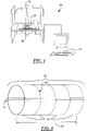
- FIG. 1 is an illustration of a method for the direct manufacture of aerospace duct elements in accordance with the present invention
- FIG. 2 is a detailed illustration of the build chamber utilized in the direct manufacturing method illustrated in FIG. 1 ;
- FIG. 3 is a detailed illustration of the assembled duct section assembled from the partial cylinder duct segments manufactured in FIG. 1 , the detail illustrating a cup and ball configuration;
- FIG. 4 is a detailed illustration of the assembled duct section assembled from the partial cylinder duct segments manufactured in FIG. 1 , the detail illustrating a t-tab and t-slot configuration;
- FIG. 5 is an illustration of the assembled duct section assembled form the partial cylinder duct segments manufactured in FIG. 1 ;
- FIG. 6 is an illustration of the elongated duct run assembled from a plurality of assembled duct sections illustrated in FIG. 5 ;
- FIG. 7 is an illustration of an alternate embodiment of the assembled duct section, the assembled duct section comprising a plurality of quarter cylinder duct segments;
- FIG. 8 is an illustration of an alternated embodiment of the assembled duct section, the assembled duct section including a flush-joint assembly.
- FIG. 1 is an illustration of a method for the direct manufacture of aerospace elements 10 in accordance with the present invention.
- the method is intended for the manufacture of oversized elements 12 such as aerospace duct sections or other aerospace cylindrical elements.
- the method utilizes a direct manufacturing assembly 14 such as a selective laser sintering assembly to generate the aerospace duct elements 12 in a single build run controlled by a computer assembly 15 .
- Selective laser sintering assemblies 14 utilize a laser 16 to directly product solid structures within a build chamber 18 during the build run.
- the build chamber 18 (or pool) has a build chamber profile 20 that is commonly too small for the manufacturing of oversized objects during single runs.
- laser sintering has been described, the present invention contemplates other layer build methodologies.
- the present method addresses this existing limitation caused by small build chamber profiles 20 by way of forming the aerospace duct sections 12 as a plurality of partial cylinder duct segments 22 (partial cylinder segments, partial segments) formed during a single build run within the build chamber 18 .
- the partial cylinder duct segments 22 are a portion of a cylinder defined by cutting a cylinder parallel to its primary axis.
- An example of half cylinder duct segments 24 ( FIG. 2 ) and quarter cylinder duct segments 26 ( FIG. 7 ) are only two of the many contemplated embodiments.
- the advantage of using these partial segments 22 is that they may have segment effective radii 28 maximized to make most efficient use of the build chamber profile 20 .
- a resultant duct section 12 can have a duct cross-sectional profile 30 ( FIG. 5 ) significantly larger than the build chamber profile 20 .
- one embodiment contemplates the use of a nested arrangement of the duct segments 22 during the build run. This will allow a plurality of duct segments 22 to be manufactured simultaneously and even possibly a plurality of duct sections 12 . Thus, each build run is maximized for efficiency and cost effectiveness. Additionally, it is contemplated the segment effective radii 28 may be varied such that an even greater number of duct segments 22 may be simultaneously manufactured within the build chamber 18 . Additionally, the use of varied effective radii 28 allows the simultaneous production of duct sections 12 with varying duct diameters 32 .
- the duct segments 22 may be joined post-build to form each of the duct sections 12 .
- An improvement contemplates the formation of mechanical lock features 34 ( FIGS. 3 and 4 ) on the first segment end 36 and second segment end 38 of each duct segment 22 .
- These mechanical lock features 34 such as snap-lock features, allow for quick and reliable joining of the segments 22 . They also make the duct segments 22 self aligning during assembly to improve assembly and reliability. Additionally, they serve to increase adhesive application area 40 such that application of an adhesive 42 makes for a solid and secure attachment joint.
- mechanical lock features 34 two specific contemplated embodiments are illustrated including a cup 44 and ball 46 configuration and a t-tab 48 and t-slot 50 configuration.
- a single duct section 12 may be formed during the single build run
- the present invention contemplates the formation of a plurality of duct sections 54 during a single build run.
- the plurality of duct sections 54 can then be joined together axially into an elongated duct run 56 .
- This allows the manufacturing from a single build run of an element that is not only has a cross-sectional profile 30 greater than the build chamber profile 20 , but additionally allows for an elongated duct run 56 with a duct length 58 that exceeds the build length of the direct manufacturing machinery.
- the mechanical lock features 34 have thus far been described in terms of longitudinal joints 59 . It should also be understood that they can be formed to facilitate radial joints 61 as well as illustrated in FIG. 6 .
- the mechanical lock features 34 may be formed such that duct inner surface 60 and duct outer surface 62 remain substantially smooth such that flow through or around the duct section 12 remains substantially laminar.
- the mechanical lock features 34 may be biased inwards or outwards to provide such smooth inner or outer surface 60 , 62 depending on design constraints. Additionally this may be accomplished by forming a segment tongue 64 and a segment groove 66 between the segment inner surface 68 and the segment outer surface 70 . This allows the segments 22 to be joined while allowing the duct inner and outer surfaces 60 , 62 to remain substantially smooth.
- the segment sidewall thickness 72 be increased in proximity to the joint region 74 such that the tongue and groove 64 , 66 are adequately supported and structural rigidity is maintained.
Abstract
Description
Claims (31)
Priority Applications (2)
| Application Number | Priority Date | Filing Date | Title |
|---|---|---|---|
| US10/907,973 US7509725B2 (en) | 2005-04-22 | 2005-04-22 | Design methodology to maximize the application of direct manufactured aerospace parts |
| US11/162,261 US7607225B2 (en) | 2005-04-22 | 2005-09-02 | Manufacture of flow optimized stiffener for improving rigidity of ducting |
Applications Claiming Priority (1)
| Application Number | Priority Date | Filing Date | Title |
|---|---|---|---|
| US10/907,973 US7509725B2 (en) | 2005-04-22 | 2005-04-22 | Design methodology to maximize the application of direct manufactured aerospace parts |
Related Child Applications (1)
| Application Number | Title | Priority Date | Filing Date |
|---|---|---|---|
| US11/162,261 Continuation-In-Part US7607225B2 (en) | 2005-04-22 | 2005-09-02 | Manufacture of flow optimized stiffener for improving rigidity of ducting |
Publications (2)
| Publication Number | Publication Date |
|---|---|
| US20060236544A1 US20060236544A1 (en) | 2006-10-26 |
| US7509725B2 true US7509725B2 (en) | 2009-03-31 |
Family
ID=37185340
Family Applications (1)
| Application Number | Title | Priority Date | Filing Date |
|---|---|---|---|
| US10/907,973 Active 2027-02-13 US7509725B2 (en) | 2005-04-22 | 2005-04-22 | Design methodology to maximize the application of direct manufactured aerospace parts |
Country Status (1)
| Country | Link |
|---|---|
| US (1) | US7509725B2 (en) |
Cited By (6)
| Publication number | Priority date | Publication date | Assignee | Title |
|---|---|---|---|---|
| US20090250834A1 (en) * | 2008-04-04 | 2009-10-08 | Huskamp Christopher S | Formed sheet metal composite tooling |
| US20100257909A1 (en) * | 2009-04-08 | 2010-10-14 | The Boeing Company | Method and Apparatus for Reducing Force Needed to Form a Shape from a Sheet Metal |
| US20110036141A1 (en) * | 2009-08-13 | 2011-02-17 | The Boeing Company | Incremental Forging |
| US20110036139A1 (en) * | 2009-08-12 | 2011-02-17 | The Boeing Company | Method For Making a Tool Used to Manufacture Composite Parts |
| US8323427B1 (en) | 2009-09-14 | 2012-12-04 | The Boeing Company | Engineered shapes from metallic alloys |
| US9682418B1 (en) | 2009-06-18 | 2017-06-20 | The Boeing Company | Method and apparatus for incremental sheet forming |
Families Citing this family (11)
| Publication number | Priority date | Publication date | Assignee | Title |
|---|---|---|---|---|
| US8985531B2 (en) * | 2007-03-27 | 2015-03-24 | The Boeing Company | Methods for system component installation utilizing direct manufactured components |
| US7977600B2 (en) * | 2007-03-27 | 2011-07-12 | The Boeing Company | Methods and systems for providing direct manufactured interconnecting assemblies |
| US20100029189A1 (en) * | 2007-03-27 | 2010-02-04 | Wood Jeffrey H | Methods for stiffening thin wall direct manufactured structures |
| US8302522B2 (en) | 2009-04-27 | 2012-11-06 | Marquez Transtech Ltée | Composite material, composite part and methods for making such |
| ITMI20091401A1 (en) * | 2009-08-03 | 2011-02-04 | Ala Ortho S R L | METHOD OF IMPLEMENTATION WITH EBM TECHNIQUE OF STACKED OBJECTS. |
| GB2476969A (en) * | 2010-01-18 | 2011-07-20 | Dental Devices Ltd Ab | Dental implant comprising a plurality of channels |
| US9845729B2 (en) * | 2013-10-08 | 2017-12-19 | Pratt & Whitney Canada Corp. | Method of manufacturing recuperator air cells |
| FR3024060B1 (en) * | 2014-07-28 | 2021-01-29 | Michelin & Cie | ADDITIVE POWDER-BASED MANUFACTURING PROCESS OF A PIECE, IN PARTICULAR A LINING FLAP FOR A TIRE MOLD, AND AN ASSOCIATED REINFORCEMENT ELEMENT |
| FR3024059A1 (en) * | 2014-07-28 | 2016-01-29 | Michelin & Cie | PROCESS FOR THE ADDITIVE MANUFACTURE OF A POWDER OF A PIECE, IN PARTICULAR A PADDING LAMINATE FOR A PNEUMATIC MOLD |
| DE102014012425A1 (en) * | 2014-08-22 | 2016-03-17 | Cl Schutzrechtsverwaltungs Gmbh | Method for producing a three-dimensional object |
| US10895315B2 (en) | 2017-07-07 | 2021-01-19 | Divergent Technologies, Inc. | Systems and methods for implementing node to node connections in mechanized assemblies |
Citations (15)
| Publication number | Priority date | Publication date | Assignee | Title |
|---|---|---|---|---|
| US3038702A (en) * | 1958-08-29 | 1962-06-12 | Harold K Trunnell | Hinged wire guide |
| US4863538A (en) | 1986-10-17 | 1989-09-05 | Board Of Regents, The University Of Texas System | Method and apparatus for producing parts by selective sintering |
| US5017753A (en) | 1986-10-17 | 1991-05-21 | Board Of Regents, The University Of Texas System | Method and apparatus for producing parts by selective sintering |
| US5132143A (en) | 1986-10-17 | 1992-07-21 | Board Of Regents, The University Of Texas System | Method for producing parts |
| US5252264A (en) * | 1991-11-08 | 1993-10-12 | Dtm Corporation | Apparatus and method for producing parts with multi-directional powder delivery |
| US5342919A (en) | 1992-11-23 | 1994-08-30 | Dtm Corporation | Sinterable semi-crystalline powder and near-fully dense article formed therewith |
| EP0703036A2 (en) | 1990-11-09 | 1996-03-27 | Dtm Corporation | Selective laser sintering apparatus with radiant heating |
| US5549416A (en) * | 1993-11-02 | 1996-08-27 | C.V. Buchan Limited | Device for joining two members together |
| US5678162A (en) | 1994-11-14 | 1997-10-14 | Board Of Regents, Univ. Of Texas System | Mold useful for injection molding of plastics, and methods of production and uses thereof |
| US5733497A (en) | 1995-03-31 | 1998-03-31 | Dtm Corporation | Selective laser sintering with composite plastic material |
| US5749041A (en) | 1995-10-13 | 1998-05-05 | Dtm Corporation | Method of forming three-dimensional articles using thermosetting materials |
| US5990268A (en) | 1992-11-23 | 1999-11-23 | Dtm Corporation | Sinterable semi-crystalline powder and near-fully dense article formed therewith |
| US6136948A (en) | 1992-11-23 | 2000-10-24 | Dtm Corporation | Sinterable semi-crystalline powder and near-fully dense article formed therewith |
| US6245281B1 (en) | 1997-10-27 | 2001-06-12 | Huels Aktiengesellschaft | Use of a nylon-12 for selective laser sintering |
| US20040021256A1 (en) | 2002-07-25 | 2004-02-05 | Degrange Jeffrey E. | Direct manufacture of aerospace parts |
-
2005
- 2005-04-22 US US10/907,973 patent/US7509725B2/en active Active
Patent Citations (16)
| Publication number | Priority date | Publication date | Assignee | Title |
|---|---|---|---|---|
| US3038702A (en) * | 1958-08-29 | 1962-06-12 | Harold K Trunnell | Hinged wire guide |
| US4863538A (en) | 1986-10-17 | 1989-09-05 | Board Of Regents, The University Of Texas System | Method and apparatus for producing parts by selective sintering |
| US5017753A (en) | 1986-10-17 | 1991-05-21 | Board Of Regents, The University Of Texas System | Method and apparatus for producing parts by selective sintering |
| US5132143A (en) | 1986-10-17 | 1992-07-21 | Board Of Regents, The University Of Texas System | Method for producing parts |
| US5639070A (en) | 1986-10-17 | 1997-06-17 | Board Of Regents, The University Of Texas System | Method for producing parts by selective sintering |
| EP0703036A2 (en) | 1990-11-09 | 1996-03-27 | Dtm Corporation | Selective laser sintering apparatus with radiant heating |
| US5252264A (en) * | 1991-11-08 | 1993-10-12 | Dtm Corporation | Apparatus and method for producing parts with multi-directional powder delivery |
| US5342919A (en) | 1992-11-23 | 1994-08-30 | Dtm Corporation | Sinterable semi-crystalline powder and near-fully dense article formed therewith |
| US5990268A (en) | 1992-11-23 | 1999-11-23 | Dtm Corporation | Sinterable semi-crystalline powder and near-fully dense article formed therewith |
| US6136948A (en) | 1992-11-23 | 2000-10-24 | Dtm Corporation | Sinterable semi-crystalline powder and near-fully dense article formed therewith |
| US5549416A (en) * | 1993-11-02 | 1996-08-27 | C.V. Buchan Limited | Device for joining two members together |
| US5678162A (en) | 1994-11-14 | 1997-10-14 | Board Of Regents, Univ. Of Texas System | Mold useful for injection molding of plastics, and methods of production and uses thereof |
| US5733497A (en) | 1995-03-31 | 1998-03-31 | Dtm Corporation | Selective laser sintering with composite plastic material |
| US5749041A (en) | 1995-10-13 | 1998-05-05 | Dtm Corporation | Method of forming three-dimensional articles using thermosetting materials |
| US6245281B1 (en) | 1997-10-27 | 2001-06-12 | Huels Aktiengesellschaft | Use of a nylon-12 for selective laser sintering |
| US20040021256A1 (en) | 2002-07-25 | 2004-02-05 | Degrange Jeffrey E. | Direct manufacture of aerospace parts |
Non-Patent Citations (2)
| Title |
|---|
| German Document No. XP 000656866, Schmachtenberg, E. et al. "Laser-Sintering of Polyamide", Kunstoffe 87 (1997), pp. 773, 774 and 776, Carl Hanser Verlag, Munich, Germany. |
| German Document No. XP 002213140, Keller, Peter "Der Stoff, aus dem die Prototypen sind (Material from which prototypes are made)" Kunstoffe 89 (1999), pp. 58-61, Carl Hanser Verlag, Munich, Germany. |
Cited By (12)
| Publication number | Priority date | Publication date | Assignee | Title |
|---|---|---|---|---|
| US20090250834A1 (en) * | 2008-04-04 | 2009-10-08 | Huskamp Christopher S | Formed sheet metal composite tooling |
| US8858853B2 (en) | 2008-04-04 | 2014-10-14 | The Boeing Company | Formed sheet metal composite tooling |
| US9409349B2 (en) | 2008-04-04 | 2016-08-09 | The Boeing Company | Formed sheet metal composite tooling |
| US20100257909A1 (en) * | 2009-04-08 | 2010-10-14 | The Boeing Company | Method and Apparatus for Reducing Force Needed to Form a Shape from a Sheet Metal |
| US8578748B2 (en) | 2009-04-08 | 2013-11-12 | The Boeing Company | Reducing force needed to form a shape from a sheet metal |
| US9682418B1 (en) | 2009-06-18 | 2017-06-20 | The Boeing Company | Method and apparatus for incremental sheet forming |
| US20110036139A1 (en) * | 2009-08-12 | 2011-02-17 | The Boeing Company | Method For Making a Tool Used to Manufacture Composite Parts |
| US8316687B2 (en) | 2009-08-12 | 2012-11-27 | The Boeing Company | Method for making a tool used to manufacture composite parts |
| US20110036141A1 (en) * | 2009-08-13 | 2011-02-17 | The Boeing Company | Incremental Forging |
| US8302450B2 (en) | 2009-08-13 | 2012-11-06 | The Boeing Company | Incremental forging |
| US8601850B2 (en) | 2009-08-13 | 2013-12-10 | The Boeing Company | Incremental forging |
| US8323427B1 (en) | 2009-09-14 | 2012-12-04 | The Boeing Company | Engineered shapes from metallic alloys |
Also Published As
| Publication number | Publication date |
|---|---|
| US20060236544A1 (en) | 2006-10-26 |
Similar Documents
| Publication | Publication Date | Title |
|---|---|---|
| US7509725B2 (en) | Design methodology to maximize the application of direct manufactured aerospace parts | |
| US7607225B2 (en) | Manufacture of flow optimized stiffener for improving rigidity of ducting | |
| US7891947B2 (en) | Turbine blade and method of fabricating the same | |
| JP5500804B2 (en) | Flexing ring and propulsion system | |
| US8834056B2 (en) | Bipod flexure ring | |
| JP4673917B2 (en) | Air duct for air conditioning of aircraft | |
| US9470243B2 (en) | Guide vane attachment structure and fan | |
| EP2492083B1 (en) | Joint structure for fiber reinforced resin and metal, and joining method for fiber reinforced resin and metal | |
| US20210046725A1 (en) | Core material for composite structures | |
| US20170342959A1 (en) | Wind turbine blade and a method of assembling a wind turbine blade and a spar cap connection piece | |
| US9914172B2 (en) | Interlocking material transition zone with integrated film cooling | |
| JP2010038158A (en) | Method and system for manufacturing blade | |
| US11149590B2 (en) | Ceramic matrix composite joints | |
| JP6255172B2 (en) | Composite structural panels and aircraft fuselage | |
| JPWO2009113350A1 (en) | Leaf seal device | |
| US9845116B2 (en) | Support structure in framework construction, and method for producing same | |
| CN103144289A (en) | Method of fabricating composite laminate structures allowing ply slippage during forming | |
| CN101909989A (en) | Wing-fuselage structural component for the connection of two airfoils and a fuselage section on an aircraft | |
| US9784284B2 (en) | Stator element for a holweck pump stage, vacuum pump having a holweck pump stage and method of manufacturing a stator element for a holweck pump stage | |
| US7438524B2 (en) | Winged structural joint and articles employing the joint | |
| US20180274507A1 (en) | Fuel rail and method of manufacturing same | |
| JP5462174B2 (en) | Aircraft fuselage structures manufactured from composite materials and aircraft equipped with such fuselage structures | |
| CN104267479B (en) | Space camera secondary mirror support structure | |
| US20060076102A1 (en) | Process for making a composite material assembly and aircraft wing and stabilizing element obtained by this process | |
| KR20190124244A (en) | Flexible Insulated Air Duct and Modular Flexible Insulated Air-Duct Systems |
Legal Events
| Date | Code | Title | Description |
|---|---|---|---|
| AS | Assignment |
Owner name: THE BOEING COMPANY, ILLINOIS Free format text: ASSIGNMENT OF ASSIGNORS INTEREST;ASSIGNORS:HUSKAMP, CHRISTOPHER S.;SLAUGHTER, VICTOR BLAKE;REEL/FRAME:015933/0523 Effective date: 20050415 |
|
| FEPP | Fee payment procedure |
Free format text: PAYOR NUMBER ASSIGNED (ORIGINAL EVENT CODE: ASPN); ENTITY STATUS OF PATENT OWNER: LARGE ENTITY Free format text: PAYER NUMBER DE-ASSIGNED (ORIGINAL EVENT CODE: RMPN); ENTITY STATUS OF PATENT OWNER: LARGE ENTITY |
|
| STCF | Information on status: patent grant |
Free format text: PATENTED CASE |
|
| FPAY | Fee payment |
Year of fee payment: 4 |
|
| FPAY | Fee payment |
Year of fee payment: 8 |
|
| MAFP | Maintenance fee payment |
Free format text: PAYMENT OF MAINTENANCE FEE, 12TH YEAR, LARGE ENTITY (ORIGINAL EVENT CODE: M1553); ENTITY STATUS OF PATENT OWNER: LARGE ENTITY Year of fee payment: 12 |