US7401111B1 - Instrument setup utility program - Google Patents
Instrument setup utility program Download PDFInfo
- Publication number
- US7401111B1 US7401111B1 US09/555,718 US55571898A US7401111B1 US 7401111 B1 US7401111 B1 US 7401111B1 US 55571898 A US55571898 A US 55571898A US 7401111 B1 US7401111 B1 US 7401111B1
- Authority
- US
- United States
- Prior art keywords
- body fluid
- significant component
- medically significant
- instrument
- port
- Prior art date
- Legal status (The legal status is an assumption and is not a legal conclusion. Google has not performed a legal analysis and makes no representation as to the accuracy of the status listed.)
- Expired - Fee Related
Links
Images


Classifications
-
- A—HUMAN NECESSITIES
- A61—MEDICAL OR VETERINARY SCIENCE; HYGIENE
- A61B—DIAGNOSIS; SURGERY; IDENTIFICATION
- A61B5/00—Measuring for diagnostic purposes; Identification of persons
- A61B5/145—Measuring characteristics of blood in vivo, e.g. gas concentration, pH value; Measuring characteristics of body fluids or tissues, e.g. interstitial fluid, cerebral tissue
- A61B5/14532—Measuring characteristics of blood in vivo, e.g. gas concentration, pH value; Measuring characteristics of body fluids or tissues, e.g. interstitial fluid, cerebral tissue for measuring glucose, e.g. by tissue impedance measurement
-
- A—HUMAN NECESSITIES
- A61—MEDICAL OR VETERINARY SCIENCE; HYGIENE
- A61B—DIAGNOSIS; SURGERY; IDENTIFICATION
- A61B5/00—Measuring for diagnostic purposes; Identification of persons
- A61B5/0002—Remote monitoring of patients using telemetry, e.g. transmission of vital signals via a communication network
-
- G—PHYSICS
- G16—INFORMATION AND COMMUNICATION TECHNOLOGY [ICT] SPECIALLY ADAPTED FOR SPECIFIC APPLICATION FIELDS
- G16H—HEALTHCARE INFORMATICS, i.e. INFORMATION AND COMMUNICATION TECHNOLOGY [ICT] SPECIALLY ADAPTED FOR THE HANDLING OR PROCESSING OF MEDICAL OR HEALTHCARE DATA
- G16H40/00—ICT specially adapted for the management or administration of healthcare resources or facilities; ICT specially adapted for the management or operation of medical equipment or devices
- G16H40/60—ICT specially adapted for the management or administration of healthcare resources or facilities; ICT specially adapted for the management or operation of medical equipment or devices for the operation of medical equipment or devices
- G16H40/63—ICT specially adapted for the management or administration of healthcare resources or facilities; ICT specially adapted for the management or operation of medical equipment or devices for the operation of medical equipment or devices for local operation
Definitions
- This invention relates to a utility program useful in, for example, the setup of, and communication with, instruments of the general type described in U.S. Pat. No. 6,635,167.
- a method of configuring a hand-held instrument for determining the concentration of a medically significant component of a body fluid or a control comprises the steps of providing a configuring computer having a first port for transmitting at least one of instructions and data for configuring the instrument, providing on the instrument a second port for receiving said at least one of instructions and data from the configuring computer, coupling said first port to said second port, transmitting said one of instructions and data to configure said instrument from said first port, receiving said one of instructions and data at said second port, and configuring said instrument according to said one of instructions and data transmitted from said first port and received at said second port.
- the step of providing a configuring computer having a first port for transmitting at least one of instructions and data for configuring the instrument comprises the step of providing a configuring computer having a first port for transmitting instructions for configuring the instrument.
- the step of providing a configuring computer having a first port for transmitting at least one of instructions and data for configuring the instrument comprises the step of providing a configuring computer having a first port for transmitting data for configuring the instrument.
- the hand-held instrument further comprises a display for displaying information related to the determined concentration.
- the step of transmitting said one of instructions and data to configure said instrument from said first port comprises the step of transmitting said one of instructions and data from said first port to configure said display.
- the method further comprises the step of transmitting one of instructions and data concerning determined concentration of a medically significant component of a body fluid from the second port to the first port.
- the step of transmitting one of instructions and data concerning determined concentration of a medically significant component of a body fluid from the second port to the first port comprises the step of transmitting data concerning determined concentration of a medically significant component of a body fluid from the instrument to the computer.
- the method further comprises updating a file in the computer with the transmitted data.
- the steps of transmitting said one of instructions and data to configure said instrument from said first port and receiving said one of instructions and data at said second port comprise transmitting said one of instructions and data through a fiber optic coupler from said first port to said second port.
- the instrument comprises an instrument for determining the glucose concentration of blood, a blood fraction or a control.
- the step of transmitting said one of instructions and data concerning determined concentration of a medically significant component of a body fluid from the second port to the first port comprises the step of transmitting said one of instructions and data concerning determined concentration of a medically significant component of a body fluid via a modem from the second port to the first port.
- FIG. 1 illustrates a diagram of a system implementing a utility program according to the present invention
- FIG. 2 illustrates installation of a utility program according to the present invention where the program is distributed on one or more disks containing the program in one or more languages;
- FIGS. 3-60 illustrate various screens displayed during the running of a utility program according to the invention.
- FIG. 1 illustrates diagrammatically a system implementing the utility program 12 of the present invention.
- Setup of such an instrument 10 is handled by a portion of the program 12 sometimes referred to hereinafter as a Meter Setup Manager through a docking station provided for the instrument 10 on a personal computer (PC) 14 .
- Communication between the docked instrument 10 and the PC 14 is coupled through a serial cable 16 such as, for example, a fiber optic connector, from a port 17 on instrument 10 to a port 18 on the PC 14 .
- a serial cable 16 such as, for example, a fiber optic connector
- Phone-In Manager is conducted via telephone modems 20 , 22 at the remote instrument 10 ′ site and the PC 14 .
- Installation of the program 12 where the program is distributed on one or more disks containing the program in one or more languages, for example, is achieved as illustrated in FIG. 2 .
- the user 24 may be asked to enter certain security information, for example, to verify the user 24 's access to the PC 14 on which the program 12 is loaded.
- a program 12 screen displays a list of utility languages from which the user 24 selects one.
- the user 24 will have to reinitialize the program 12 if, after selection of a utility language, the user 24 decides to select a different utility language.
- a Meter Setup Manager icon for example, an illustration of the instrument 10 , will appear on one of the early screens.
- a copyright screen will appear briefly and will be followed by a “Welcome” screen illustrated in FIG. 3 .
- the “Welcome” screen includes a list of tasks the Meter Setup Manager is capable of performing at the user 24 's option. This “Welcome” screen can be deselected at the user 24 's option. If the user 24 has deselected this screen, the default task will be initialized. If the user 24 has selected the “Create a Meter Setup” option, a standard Microsoft® Windows® development tool, known as the WizardTM, is launched.
- FIG. 5 illustrates the “Enter personal information” screen.
- This screen displays three fields into which the user 24 is directed to enter information pertinent to the patient whose instrument 10 is being set up.
- the fields are patient name, patient identification, such as, for example, patient number, patient social security number, and so on, and health care provider computer 14 phone number.
- the next screen, illustrated in FIG. 6 is the “Glucose units/glucose ranges” screen.
- the user 24 sets up the patient's instrument 10 's glucose upper limit, glucose lower limit, hypoglycemic limit, and units of glucose measurement, for example, millimoles per liter (mmol/L) or milligrams per deciliter (mg/dL).
- the next screen, illustrated in FIG. 7 prompts the user 24 to set up the patient's instrument 10 for the type(s) of insulin the patient is to take, for example, REGular, NPH or 90/10, and the dosage increments, for example, tenths of a unit, half units, or whole units.
- the user 24 is prompted to load into the patient's instrument 10 certain events which the patient is then capable of entering into the patient's diary, which the instrument 10 is equipped to keep. From a library of, for example, 255 events, fifteen are chosen from which the patient may select to enter one in his or her diary with each glucose test result. Some one or more of these may be customized for the patient whose instrument 10 is being set up.
- the next screen permits the user 24 to load into the patient's instrument 10 schedule control over any twenty-four hour period.
- a glucose test entry regimen dividing the twenty-four hour day into eight two-to five-hour intervals is the default regimen. This default regimen will be displayed on the screen, and the user 24 will be permitted to edit away from the default settings for the individual patient. Editing is done by clicking on the “Edit” button or by double clicking on any of the time block entries. Once the time block to be edited has been highlighted, its entries are available for edit.
- the program requires that every minute of the twenty-four hour period be accounted for, and does not permit any minute to be in two different time blocks. As a result, adjusting an entry will typically result in an automatic adjustment of another entry.
- the information just entered is combined in the “Time block information” screen.
- the insulin types that were selected in the screen illustrated in FIG. 7 are the ones displayed on the screen illustrated in FIG. 10 . If insulin type “None” was selected in connection with the setup illustrated in FIG. 7 , no dosage can be selected in connection with the setup illustrated in FIG. 10 . If the user 24 does not select an exercise type, he may not enter an exercise duration.
- the events list contains events which were selected in the events screen. The program does not permit the user 24 to list an event on the screen illustrated in FIG. 10 which was not one of the selected events in FIG. 8 .
- the screen illustrated in FIG. 11 is the meter setup “Insulin pump profile” screen.
- This screen contains a schedule list box similar to the time blocks schedule list box illustrated in FIG. 9 .
- the user 24 selects an insulin type, and a start date and time for the insulin pump profile.
- the profile can contain no less than one time block and no more than twelve.
- the user 24 can insert or edit a time block from the screen.
- the user 24 can only delete a time block when the profile contains more than one time block.
- the user 24 may insert a new time block by selecting a time block from the list and selecting the “Insert” button.
- the user 24 is presented with the option to insert the new time block either before or after the selected time block.
- the new time block with a duration of one half hour, is inserted into the schedule list box.
- the user 24 can edit the start time of the newly added time block by double clicking on its entry in the list box, or by selecting the “Edit” button.
- the user 24 can edit a specific insulin pump profile time block by double clicking on its entry in the profile time block list box. See FIG. 13 . When this is done, the start time and insulin pump rate for the selected time block can be edited.
- the user 24 can also edit a time block by highlighting its entry in the time block list box and selecting the “Edit” button. All times must be part of some time block, so the user interface does not permit gaps between time blocks. Nor can time blocks overlap. Setting the start time of one block automatically adjusts the end time of the previous time block to end one minute before.
- the user 24 can also delete a specific profile time block by highlighting its entry in the profile list box and selecting the “Delete” button. Unless the selected time block is the first time block, the preceding time block's end time will be adjusted appropriately so that there are no gaps in the profile schedule. If the selected time block is the first time block, then the following time block's start time will be adjusted appropriately.
- a number of miscellaneous options relating primarily to the display of information on the instrument 10 are also user 24 selectable.
- the format in which decimals are displayed (X.X or X,X), whether a 24 hour clock or a twelve hour one (with AM and PM), the date format (month, day, year or day, month, year), whether the instrument 10 display 28 is to be backlit or not, and whether the instrument 10 's audio beeper is to be activated or not, are displayed for selection.
- the user 24 selects from among a number, for example, eight, of languages in which instruments 10 can be programmed to display information, a number, for example, four, in which the particular instrument 10 being set up can display information at the patient's option.
- the “Tip Messages” screen illustrated in FIG. 16 , enables a list control that permits the user 24 to select a number, for example, ten, of tip messages for display on the instrument 10 being set up. If the user 24 does not want tip messages displayed on the patient's instrument 10 , the user 24 may deselect the “Tip Messages Enabled for Meter Setup” box. If this box is not checked, the user 24 must select individual messages which the user 24 wants to appear on the patient's instrument 10 at appropriate times.
- the user 24 may add custom tip messages to an instrument 10 being set up for a patient. To do this, the user 24 selects the “Custom” button. The screen illustrated in FIG. 17 is displayed. If the user 24 then selects the “Add” button, the screen illustrated in FIG. 18 is displayed. If the user 24 selects the “Edit” button, the screen illustrated in FIG. 19 is displayed. If the user 24 selects the “Remove” button, the tip message highlighted in the screen illustrated in FIG. 17 is deleted. Once these screens have been completed, the instrument 10 setup is complete. The user 24 is presented with a dialog and given instructions on how to view and save the completed setup. This screen is illustrated in FIG. 20 .
- the user 24 selects the “Retrieve an Existing Meter Setup from a Meter” option, and no instrument 10 is connected to the PC 14 , the user 24 is asked to connect the instrument 10 to the PC 14 . If the user 24 selects “OK” and no instrument 10 is yet connected to the PC 14 , the user 24 is again asked to connect the instrument 10 to the PC 14 . If the user 24 selects “Cancel,” the “Welcome” screen of FIG. 3 again appears. If the user 24 selects “Help,” the help facility is launched with troubleshooting information regarding connecting an instrument 10 to the PC 14 .
- a summary screen of the general configuration illustrated in FIG. 21 will be displayed.
- This screen displays the instrument 10 setup.
- the user 24 may edit this setup by selecting the highlighted text on the screen.
- the user 24 is then presented with the appropriate instrument 10 setup tab to edit instrument 10 setup options.
- the basic elements of the summary screen as they appear on the Microsoft® Windows® 95 platform are illustrated in FIG. 21 .
- the title bar contains a descriptor for the data contained in the client area followed by the name of the software. This descriptor may be “New Meter,” a filename, or a designation such as “John Smith's Meter.” Below the title bar is a menu bar. The menu bar is described later.
- This summary screen contains the current instrument 10 setup settings.
- the user 24 may edit the information contained on this screen by clicking on the underlined text.
- the tab control contains screens that are nearly identical to the ones available via the instrument 10 setup WizardTM, with the difference being that the WizardTM provides a simple, step-by-step approach to entering data, whereas the tab control gives the user 24 one-click access to any screen.
- the tabs can also be used to set up instruments 10 . They provide a somewhat more powerful tool for doing this. However, it is suggested that, for the first few times at least, the user 24 perform instrument 10 setup using the WizardTM as a learning tool.
- the contents of the “Personal” tab are illustrated. As will be appreciated, the contents of this tab, and the appropriate user 24 interactions, are generally as described in connection with the screen illustrated in FIG. 5 .
- the contents of the “Glucose units/ranges” tab and the appropriate user interactions are generally as described in connection with the screen illustrated in FIG. 6 .
- the contents of the “Insulin type” tab are illustrated. These contents and the associated user 24 interactions are generally as described in connection with the screen illustrated in FIG. 7 .
- the contents of the “Event markers” tab and the related user 24 interactions are generally as described in connection with the screen illustrated in FIG. 8 .
- FIG. 27 the contents of the “Time blocks” tab are illustrated. These contents and the associated user 24 interactions are generally as described in connection with the screen illustrated in FIG. 9 .
- FIG. 28 the contents of the “Time blocks” tab and user 24 interactions are generally as described in connection with the screen illustrated in FIG. 10 .
- FIG. 29 the contents of the “insulin pump profile” tab and the related user 24 interactions are generally as described in connection with the screen illustrated in FIG. 11 .
- FIG. 30 the contents of the “Miscellaneous options” tab and user 24 interactions associated with it are generally as described in connection with the screen illustrated in FIG. 14 .
- the contents of the “Language” tab and user 24 interactions associated with it are generally as described in connection with the screen illustrated in FIG. 15 .
- the contents of the “Tip messages” tab and user 24 interactions associated with it are generally as described in connection with the screen illustrated in FIG. 16 .
- the user 24 may press a function key, F 1 in the illustrated example, to open the help facility and obtain context sensitive help. All dialogs also have associated help buttons which access the help facility.
- the instrument 10 setup manager also has a help menu. The user 24 may cancel from the “Welcome” screen by selecting the “Cancel” button on that screen. When that action is taken, the welcome dialog box illustrated in FIG. 3 is dismissed and the main screen is displayed.
- the user may select “Retrieve Patient Data from a Meter” connected to the computer 14 from the “Welcome” screen. If the user 24 then selects “OK,” a sequence to retrieve patient data from a connected instrument 10 is initiated. This is exactly equivalent to selecting the “Retrieve Patient Data” option from the Meter menu.
- the Meter Setup Manager functions are divided into “File,” “Meter,” “View” and “Help” menus. See, for example, FIG. 21 .
- the options under the “File” menu include “New,” “Open . . . ,” “Close,” “Save,” “Save As . . . ,” “Print,” “View Patient Report . . . ,” “Print Patient Report . . . ,” “Edit Patient Database . .
- the options under the “Meter” menu include “Retrieve Patient Data,” “Retrieve Meter Setup,” “Send Meter Setup,” “Clear Patient Diary” and “COMmunication Port Settings . . . ”
- the options under the “View” menu include “Toolbar,” “Status Bar” and “Options . . . ”
- the options under the “Help” menu include “Help topics” and “About . . . .”
- the “File” menu contains commands that operate on Meter Setup Data and Patient Data. “New” returns all fields to their default states and initially opens a new instrument 10 setup with the Meter Setup Wizard. The user 24 may change this setting to Meter Setup Tabs by selecting “Options” under the “View” menu. If there is any unsaved data in the fields, the user 24 is prompted to save it. “Open” prompts the user 24 to name a file to open and opens a Meter Setup File. If the selected file is not an instrument 10 setup file, an error message is displayed and the Summary Screen is blank. If the selected file is an instrument 10 setup file, then the data is initially displayed with the Summary Screen. The user 24 may edit the open document with the Meter Setup Tabs by clicking on the underlined text, or may edit the open document with the Meter Setup WizardTM by selecting the WizardTM toolbar button.
- “Close” closes the currently open instrument 10 setup file. If the currently open instrument 10 setup file has not been saved, the user 24 will be prompted to save it. “Save” saves the currently open file. If the file has not yet been assigned a name, the user 24 will be prompted to assign it a name and location. “Save As” saves the current file under the assigned name. The user 24 is prompted to assign it a name and location. “Print” prints the current instrument 10 setup data. “View Patient Report . . . ” prompts the user 24 to identify a patient data file to view using the patient name, instrument 10 serial number and the date received or the actual file name to select the file for viewing. “View Patient Report . . .
- FIG. 33 causes the selected report to be displayed in the format specified by the user 24 . See FIG. 33 .
- the user 24 selects the report format by selecting “Options” from the “View” menu.
- “View Patient Report Browser,” FIG. 34 is accessed by the user 24 clicking on the “Browse . . . . ” button on the screen illustrated in FIG. 33 .
- “View Patient Report Browser” permits the user 24 to scroll through the patient reports saved in the database for one the user wishes to view.
- “Print Patient Report . . . ” causes the selected report to be printed.
- the user 24 selects the report to be printed in response to a prompt from this routine. See FIG. 35 . “Print Patient Report Browser,” FIG.
- the “Meter” menu contains commands that act upon the instrument 10 that is connected to the computer 14 .
- “Retrieve Patient Data” prompts the user 24 to enter a filename and a location to save the patient data to, and then retrieves the patient data from the instrument 10 connected to the computer 14 . If no instrument 10 is connected to the computer 14 , the user 24 is prompted to connect one. Once the data transfer is complete, the patient data is displayed in the format selected by the user 24 .
- An “Options” screen illustrated in FIG. 39 permits the user 24 to select various Meter Setup Manager application options.
- the user 24 is prompted to select from among the various report formats: “Diary,” “Glucose values,” Trend,” “Glucose graph,” “Average trend,” Glucose ranges,” and “Hypoglycemic events.”
- the user 24 is also prompted to select the time range for average trend, glucose ranges and hypoglycemic events reports.
- the user 24 is further prompted to select the glucose units, for example, mg/dL or mmol/L, for the reports.
- the user 24 is prompted to select how new instrument 10 setup will be performed, permitting the user 24 to select the Meter Setup WizardTM, or use the tabs, or instructing the Meter Setup Manager always to ask how instrument 10 setup is to be performed. See FIG. 40 and the discussion of FIG. 22 above.
- the user 24 is prompted to select the computer 14 port 18 through which communication with the instrument 10 will be conducted. See FIG. 41 .
- the user 24 is prompted to indicate whether the “Welcome” screen, FIG. 3 , should be displayed at startup.
- FIG. 43 illustrates the screen which is displayed when instrument 10 setup status data is being transferred.
- the “Enter Patient Name” prompt appears, FIG. 44 , prompting the user 24 to enter the patient's name. The entered patient's name then appears on the summary screen.
- “Send Meter Setup” sends instrument 10 setup data to an instrument 10 connected to the computer 14 . If no instrument 10 is connected to the computer 14 , the user 24 will be prompted to connect one. Before the instrument 10 setup data is sent to the instrument 10 , the user 24 is prompted to set the date and time on the instrument 10 . The user 24 has the option of not changing the instrument 10 's date and time, synchronizing the instrument 10 's date and time to the computer 14 's or manually setting the instrument 10 's date and time. See FIG. 45 . As the instrument 10 setup data is being sent to the instrument 10 , the screen illustrated in FIG. 46 is displayed.
- “Clear Patient Diary” clears the patient diary data of an instrument 10 connected to the computer 14 .
- the user 24 is prompted to save patient data to files before proceeding with clearing of patient diary from an instrument 10 . If no instrument 10 is connected to the computer 14 , the user 24 will be prompted to connect one.
- “COM Port Settings” causes the screen illustrated in FIG. 47 to be displayed. The user 24 is prompted to select the computer 14 port 18 through which communication with the instrument 10 will be conducted.
- the “View” menu contains items that adjust the settings for the Meter Setup Manager.
- the “Toolbar” command permits the user 24 to select whether the toolbar is displayed.
- the “Status Bar” command permits the user 24 to select whether the status bar, which is located at the bottom of the Meter Setup Manager application screen, is displayed.
- “Options” creates a display which permits the user 24 to choose various Meter Setup Manager application options. This multi-page display is illustrated in FIGS. 48-51 . See the above discussion of FIGS. 39-42 .
- the “Help” menu contains items that provide the user 24 with access to information about the Meter Setup Manager.
- “Help Topics” displays the table of contents of a help file. The user 24 may navigate via hyperlinks from the table of contents to the contents of the various help file entries.
- the “About” entry causes the version of the software and copyright notice information to be displayed.
- the toolbar for the Meter Setup Manager contains command buttons for commonly accessed features, such as “File-New,” “File-Open,” “File-Save,” “File-Print,” “Meter Setup Wizard,” “Meter Communication-Retrieve Meter Setup,” “Meter Communication-Send Meter Setup” and “Meter Communication-Retrieve Patient Data.”
- Phone-In Manager is always running, at least as a background task. It will be active only when a phone call comes in to the health care professional's office computer 14 or when a user 24 restores it to display status on the computer 14 monitor. A user 24 restores Phone-In Manager, for example, to review calls or to change any of the Phone-In Manager configuration options.
- FIG. 52 illustrates the Phone-In Manager main screen restored. When patients phone their data in via modems 20 , 22 to the health care professional's computer 14 , the Phone-In Manager keeps track of each call and the data that was received.
- All calls are logged in order from most recent to oldest. Each logged call is displayed in the list with the instrument 10 ′ serial number, patient's name if available, and the time and date of the phone call.
- the user 24 of the computer 14 may view or print patient data by highlighting the desired patient's instrument 10 ′ serial number and selecting the “View” or “Print” button, respectively.
- the user 24 may also select the “Auto Print” option, in which case incoming patient data is automatically printed.
- the user 24 may also view or print patient data which has expired from the Recent Calls list displayed in the screen illustrated in FIG. 52 . Selecting the “View” button results in the display of the selected patient's data in the format illustrated in FIG. 53 .
- the user 24 can then choose to print or close this file.
- the user 24 can also view this screen by selecting old files to view from the menu.
- the files can be selected by the serial number of the instrument 10 ′, patient name and data transfer date, or by file name. Selecting the “Print” button results in the printing of the selected patient's data in the report format illustrated in FIG. 53 .
- the user 24 can also print files which have expired from the Recent Calls list by selecting old files to print from the menu. Again, the files to be printed can be selected by the serial number of the instrument 10 ′, patient name and data transfer date, or by file name. If the “Auto Print” check box is checked, patient reports will be printed upon receipt.
- the “View” menu contains menu items that permit the user 24 to view and modify various Phone-In Manager data stores.
- the “Status Bar” permits the user 24 to turn the status bar at the bottom of the main window on or off.
- “Phone Line Status” displays a dialog, illustrated in FIG. 54 , containing the states of all phone lines. This permits the user 24 to enable or disable one or more of the phone lines 23 connected to the computer 14 .
- the utility program 12 is running in Windows® 95 and the user 24 clicks on the “Add” button or the “Properties” button on the screen illustrated in FIG. 54 , the screen illustrated in FIG. 55 is displayed. This screen permits the user 24 to select from modems 20 , 22 configured using the control panel.
- the screen illustrated in FIG. 56 is displayed. This screen prompts the user 24 to set the serial port and baud rate for the modems 20 , 22 .
- the screen illustrated in FIG. 57 is displayed. This screen permits the user 24 to modify modem 20 , 22 strings.
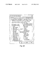
- “Call Statistics” causes a screen illustrated in FIG. 58 to be displayed. Statistics for each phone line connected to the computer 14 are displayed. Statistics include the number of calls made to the line, the number of patient data transfers attempted, and the number of patient data transfers which succeeded. This screen also permits the user 24 to reset the statistics. “Options” permits the user 24 to modify the Phone-In Manager options. There are two tabs under “Options.” One tab, “Report Settings,” is illustrated in FIG. 59 . This page permits the user 24 to select the type of Patient Data Report to view. The other tab, “Miscellaneous Options,” is illustrated in FIG. 60 . This page permits the user 24 to select how many files are kept for each patient, and how many days' calls are kept in the Recent Calls list. It also permits the user 24 to select to have patient reports printed automatically.
- the “Help” menu contains items that provide the user 24 with access to information about the Phone-In Manager.
- “Help Topics” displays the table of contents of a help file. The user 24 may navigate via hyperlinks from the table of contents to the contents of the various help file entries.
- the “About” entry causes the version of the utility program 12 and copyright notice information to be displayed.
Abstract
Description
Claims (32)
Priority Applications (1)
| Application Number | Priority Date | Filing Date | Title |
|---|---|---|---|
| US09/555,718 US7401111B1 (en) | 1997-12-04 | 1998-12-04 | Instrument setup utility program |
Applications Claiming Priority (3)
| Application Number | Priority Date | Filing Date | Title |
|---|---|---|---|
| US6749997P | 1997-12-04 | 1997-12-04 | |
| US09/555,718 US7401111B1 (en) | 1997-12-04 | 1998-12-04 | Instrument setup utility program |
| PCT/US1998/025850 WO1999027849A1 (en) | 1997-12-04 | 1998-12-04 | Instrument setup utility program |
Publications (1)
| Publication Number | Publication Date |
|---|---|
| US7401111B1 true US7401111B1 (en) | 2008-07-15 |
Family
ID=22076387
Family Applications (1)
| Application Number | Title | Priority Date | Filing Date |
|---|---|---|---|
| US09/555,718 Expired - Fee Related US7401111B1 (en) | 1997-12-04 | 1998-12-04 | Instrument setup utility program |
Country Status (7)
| Country | Link |
|---|---|
| US (1) | US7401111B1 (en) |
| EP (1) | EP1030590B1 (en) |
| AU (1) | AU728964B2 (en) |
| CA (1) | CA2309841C (en) |
| DE (1) | DE69808965T2 (en) |
| ES (1) | ES2186247T3 (en) |
| WO (1) | WO1999027849A1 (en) |
Cited By (15)
| Publication number | Priority date | Publication date | Assignee | Title |
|---|---|---|---|---|
| US20070266109A1 (en) * | 2006-05-11 | 2007-11-15 | Mark Mellott | Apparatus and method for sharing data among multiple terminal devices |
| US20080214906A1 (en) * | 2006-03-21 | 2008-09-04 | Nellcor Puritan Bennett Llc | Patient Monitoring Help Video System and Method |
| US20100280782A1 (en) * | 2009-04-29 | 2010-11-04 | Abbott Diabetes Care Inc. | Method and System for Providing Real Time Analyte Sensor Calibration with Retrospective Backfill |
| US8346335B2 (en) | 2008-03-28 | 2013-01-01 | Abbott Diabetes Care Inc. | Analyte sensor calibration management |
| US8497777B2 (en) | 2009-04-15 | 2013-07-30 | Abbott Diabetes Care Inc. | Analyte monitoring system having an alert |
| US8514086B2 (en) | 2009-08-31 | 2013-08-20 | Abbott Diabetes Care Inc. | Displays for a medical device |
| US8597188B2 (en) | 2007-06-21 | 2013-12-03 | Abbott Diabetes Care Inc. | Health management devices and methods |
| US8617069B2 (en) | 2007-06-21 | 2013-12-31 | Abbott Diabetes Care Inc. | Health monitor |
| US9069536B2 (en) | 2011-10-31 | 2015-06-30 | Abbott Diabetes Care Inc. | Electronic devices having integrated reset systems and methods thereof |
| US9339217B2 (en) | 2011-11-25 | 2016-05-17 | Abbott Diabetes Care Inc. | Analyte monitoring system and methods of use |
| US9532737B2 (en) | 2011-02-28 | 2017-01-03 | Abbott Diabetes Care Inc. | Devices, systems, and methods associated with analyte monitoring devices and devices incorporating the same |
| US10136816B2 (en) | 2009-08-31 | 2018-11-27 | Abbott Diabetes Care Inc. | Medical devices and methods |
| US11006871B2 (en) | 2009-02-03 | 2021-05-18 | Abbott Diabetes Care Inc. | Analyte sensor and apparatus for insertion of the sensor |
| US11071455B2 (en) | 2013-12-31 | 2021-07-27 | Senseonics, Incorporated | Continuous analyte monitoring system |
| US11793936B2 (en) | 2009-05-29 | 2023-10-24 | Abbott Diabetes Care Inc. | Medical device antenna systems having external antenna configurations |
Families Citing this family (2)
| Publication number | Priority date | Publication date | Assignee | Title |
|---|---|---|---|---|
| US8423386B2 (en) | 2007-12-20 | 2013-04-16 | Terumo Kabushiki Kaisha | Blood sugar measured level management system and blood sugar level measurement apparatus |
| US9907492B2 (en) | 2012-09-26 | 2018-03-06 | Abbott Diabetes Care Inc. | Method and apparatus for improving lag correction during in vivo measurement of analyte concentration with analyte concentration variability and range data |
Citations (32)
| Publication number | Priority date | Publication date | Assignee | Title |
|---|---|---|---|---|
| US4370983A (en) * | 1971-01-20 | 1983-02-01 | Lichtenstein Eric Stefan | Computer-control medical care system |
| US4383534A (en) | 1980-06-05 | 1983-05-17 | Peters Jeffrey L | Vital signs monitoring apparatus |
| US4637403A (en) | 1985-04-08 | 1987-01-20 | Garid, Inc. | Glucose medical monitoring system |
| US4696309A (en) | 1983-04-12 | 1987-09-29 | Eberhart Stephan | Portable apparatus for taking blood samples |
| US5113869A (en) * | 1990-08-21 | 1992-05-19 | Telectronics Pacing Systems, Inc. | Implantable ambulatory electrocardiogram monitor |
| US5307263A (en) * | 1992-11-17 | 1994-04-26 | Raya Systems, Inc. | Modular microprocessor-based health monitoring system |
| US5361336A (en) | 1991-11-21 | 1994-11-01 | Hewlett-Packard Company | Method for controlling an instrument through a common instrument programming interface |
| US5368562A (en) | 1993-07-30 | 1994-11-29 | Pharmacia Deltec, Inc. | Systems and methods for operating ambulatory medical devices such as drug delivery devices |
| US5570682A (en) | 1993-12-14 | 1996-11-05 | Ethex International, Inc. | Passive inspiratory nebulizer system |
| US5606164A (en) | 1996-01-16 | 1997-02-25 | Boehringer Mannheim Corporation | Method and apparatus for biological fluid analyte concentration measurement using generalized distance outlier detection |
| US5619991A (en) | 1995-04-26 | 1997-04-15 | Lucent Technologies Inc. | Delivery of medical services using electronic data communications |
| US5630664A (en) * | 1995-12-20 | 1997-05-20 | Farrelly; Patricia A. | Hand held apparatus for performing medical calculations |
| US5724983A (en) | 1994-08-01 | 1998-03-10 | New England Center Hospitals, Inc. | Continuous monitoring using a predictive instrument |
| US5735285A (en) | 1996-06-04 | 1998-04-07 | Data Critical Corp. | Method and hand-held apparatus for demodulating and viewing frequency modulated biomedical signals |
| US5827180A (en) * | 1994-11-07 | 1998-10-27 | Lifemasters Supported Selfcare | Method and apparatus for a personal health network |
| US5846224A (en) * | 1996-10-01 | 1998-12-08 | Baxter International Inc. | Container for use with blood warming apparatus |
| US5889474A (en) * | 1992-05-18 | 1999-03-30 | Aeris Communications, Inc. | Method and apparatus for transmitting subject status information over a wireless communications network |
| US5944659A (en) * | 1995-11-13 | 1999-08-31 | Vitalcom Inc. | Architecture for TDMA medical telemetry system |
| US5974124A (en) * | 1997-01-21 | 1999-10-26 | Med Graph | Method and system aiding medical diagnosis and treatment |
| US5997476A (en) * | 1997-03-28 | 1999-12-07 | Health Hero Network, Inc. | Networked system for interactive communication and remote monitoring of individuals |
| US6072396A (en) * | 1994-12-30 | 2000-06-06 | Advanced Business Sciences | Apparatus and method for continuous electronic monitoring and tracking of individuals |
| US6186145B1 (en) * | 1994-05-23 | 2001-02-13 | Health Hero Network, Inc. | Method for diagnosis and treatment of psychological and emotional conditions using a microprocessor-based virtual reality simulator |
| US6408330B1 (en) * | 1997-04-14 | 2002-06-18 | Delahuerga Carlos | Remote data collecting and address providing method and apparatus |
| US6427088B1 (en) * | 2000-01-21 | 2002-07-30 | Medtronic Minimed, Inc. | Ambulatory medical apparatus and method using telemetry system with predefined reception listening periods |
| US6441747B1 (en) * | 2000-04-18 | 2002-08-27 | Motorola, Inc. | Wireless system protocol for telemetry monitoring |
| US20020169636A1 (en) * | 1995-03-13 | 2002-11-14 | Eggers Philip N. | System and method for managing patient care |
| US6516227B1 (en) * | 1999-07-27 | 2003-02-04 | Advanced Bionics Corporation | Rechargeable spinal cord stimulator system |
| US20030229514A2 (en) * | 1992-11-17 | 2003-12-11 | Stephen Brown | Multi-user remote health monitoring system with biometrics support |
| US6673596B1 (en) * | 1997-11-25 | 2004-01-06 | Ut-Battelle, Llc | In vivo biosensor apparatus and method of use |
| US20050104577A1 (en) * | 1997-02-26 | 2005-05-19 | Eusebiu Matei | System for determining relative distance(s) and/or angle(s) between at least two points |
| US20050137648A1 (en) * | 1997-02-26 | 2005-06-23 | Gregoire Cosendai | System and method suitable for treatment of a patient with a neurological deficit by sequentially stimulating neural pathways using a system of discrete implantable medical devices |
| US7114502B2 (en) * | 1997-02-26 | 2006-10-03 | Alfred E. Mann Foundation For Scientific Research | Battery-powered patient implantable device |
Family Cites Families (1)
| Publication number | Priority date | Publication date | Assignee | Title |
|---|---|---|---|---|
| US5558638A (en) * | 1993-04-30 | 1996-09-24 | Healthdyne, Inc. | Patient monitor and support system |
-
1998
- 1998-12-04 WO PCT/US1998/025850 patent/WO1999027849A1/en active IP Right Grant
- 1998-12-04 AU AU19041/99A patent/AU728964B2/en not_active Expired
- 1998-12-04 CA CA002309841A patent/CA2309841C/en not_active Expired - Lifetime
- 1998-12-04 EP EP98963794A patent/EP1030590B1/en not_active Expired - Lifetime
- 1998-12-04 ES ES98963794T patent/ES2186247T3/en not_active Expired - Lifetime
- 1998-12-04 DE DE69808965T patent/DE69808965T2/en not_active Expired - Lifetime
- 1998-12-04 US US09/555,718 patent/US7401111B1/en not_active Expired - Fee Related
Patent Citations (32)
| Publication number | Priority date | Publication date | Assignee | Title |
|---|---|---|---|---|
| US4370983A (en) * | 1971-01-20 | 1983-02-01 | Lichtenstein Eric Stefan | Computer-control medical care system |
| US4383534A (en) | 1980-06-05 | 1983-05-17 | Peters Jeffrey L | Vital signs monitoring apparatus |
| US4696309A (en) | 1983-04-12 | 1987-09-29 | Eberhart Stephan | Portable apparatus for taking blood samples |
| US4637403A (en) | 1985-04-08 | 1987-01-20 | Garid, Inc. | Glucose medical monitoring system |
| US5113869A (en) * | 1990-08-21 | 1992-05-19 | Telectronics Pacing Systems, Inc. | Implantable ambulatory electrocardiogram monitor |
| US5361336A (en) | 1991-11-21 | 1994-11-01 | Hewlett-Packard Company | Method for controlling an instrument through a common instrument programming interface |
| US5889474A (en) * | 1992-05-18 | 1999-03-30 | Aeris Communications, Inc. | Method and apparatus for transmitting subject status information over a wireless communications network |
| US5307263A (en) * | 1992-11-17 | 1994-04-26 | Raya Systems, Inc. | Modular microprocessor-based health monitoring system |
| US20030229514A2 (en) * | 1992-11-17 | 2003-12-11 | Stephen Brown | Multi-user remote health monitoring system with biometrics support |
| US5368562A (en) | 1993-07-30 | 1994-11-29 | Pharmacia Deltec, Inc. | Systems and methods for operating ambulatory medical devices such as drug delivery devices |
| US5570682A (en) | 1993-12-14 | 1996-11-05 | Ethex International, Inc. | Passive inspiratory nebulizer system |
| US6186145B1 (en) * | 1994-05-23 | 2001-02-13 | Health Hero Network, Inc. | Method for diagnosis and treatment of psychological and emotional conditions using a microprocessor-based virtual reality simulator |
| US5724983A (en) | 1994-08-01 | 1998-03-10 | New England Center Hospitals, Inc. | Continuous monitoring using a predictive instrument |
| US5827180A (en) * | 1994-11-07 | 1998-10-27 | Lifemasters Supported Selfcare | Method and apparatus for a personal health network |
| US6072396A (en) * | 1994-12-30 | 2000-06-06 | Advanced Business Sciences | Apparatus and method for continuous electronic monitoring and tracking of individuals |
| US20020169636A1 (en) * | 1995-03-13 | 2002-11-14 | Eggers Philip N. | System and method for managing patient care |
| US5619991A (en) | 1995-04-26 | 1997-04-15 | Lucent Technologies Inc. | Delivery of medical services using electronic data communications |
| US5944659A (en) * | 1995-11-13 | 1999-08-31 | Vitalcom Inc. | Architecture for TDMA medical telemetry system |
| US5630664A (en) * | 1995-12-20 | 1997-05-20 | Farrelly; Patricia A. | Hand held apparatus for performing medical calculations |
| US5606164A (en) | 1996-01-16 | 1997-02-25 | Boehringer Mannheim Corporation | Method and apparatus for biological fluid analyte concentration measurement using generalized distance outlier detection |
| US5735285A (en) | 1996-06-04 | 1998-04-07 | Data Critical Corp. | Method and hand-held apparatus for demodulating and viewing frequency modulated biomedical signals |
| US5846224A (en) * | 1996-10-01 | 1998-12-08 | Baxter International Inc. | Container for use with blood warming apparatus |
| US5974124A (en) * | 1997-01-21 | 1999-10-26 | Med Graph | Method and system aiding medical diagnosis and treatment |
| US20050104577A1 (en) * | 1997-02-26 | 2005-05-19 | Eusebiu Matei | System for determining relative distance(s) and/or angle(s) between at least two points |
| US7114502B2 (en) * | 1997-02-26 | 2006-10-03 | Alfred E. Mann Foundation For Scientific Research | Battery-powered patient implantable device |
| US20050137648A1 (en) * | 1997-02-26 | 2005-06-23 | Gregoire Cosendai | System and method suitable for treatment of a patient with a neurological deficit by sequentially stimulating neural pathways using a system of discrete implantable medical devices |
| US5997476A (en) * | 1997-03-28 | 1999-12-07 | Health Hero Network, Inc. | Networked system for interactive communication and remote monitoring of individuals |
| US6408330B1 (en) * | 1997-04-14 | 2002-06-18 | Delahuerga Carlos | Remote data collecting and address providing method and apparatus |
| US6673596B1 (en) * | 1997-11-25 | 2004-01-06 | Ut-Battelle, Llc | In vivo biosensor apparatus and method of use |
| US6516227B1 (en) * | 1999-07-27 | 2003-02-04 | Advanced Bionics Corporation | Rechargeable spinal cord stimulator system |
| US6427088B1 (en) * | 2000-01-21 | 2002-07-30 | Medtronic Minimed, Inc. | Ambulatory medical apparatus and method using telemetry system with predefined reception listening periods |
| US6441747B1 (en) * | 2000-04-18 | 2002-08-27 | Motorola, Inc. | Wireless system protocol for telemetry monitoring |
Non-Patent Citations (7)
| Title |
|---|
| [1997] Lightweight, Mobile E-Mail for Intra-Clinic Communication www.amia.org/pubs/symposia/D004447.PDF. * |
| Automated measurement of retinal vascular tortuosity-Hart, Goldbaum (1997) ; ftp.cs.sandia.gov/pub/papers/wehart/1997/HarGolCotKubNel97-amia.ps.gz. * |
| Chap8p1-Converted; www.vandersluis.net/book/Chap8.html. * |
| Clinical Applications of Palmtop Computing Annotated Bibliography www.cs.umbc.edu/~mikeg/palm.html. * |
| Information technology resources to support persons involved with diabetes; www.lehigh.edu/lists/diabetic/html/software.html. * |
| Securing Radio Spectrum for Wireless Internet Access www.isoc.org/isoc/whatis/conferences/inet/96/proceedings/g1/g1<SUB>-</SUB>4.htm. * |
| Temporal Abstractions for Diabetic Patients Management-Cristiana Larizza (1997) ; aim.unipv.it/pub/papers/larizza/aime97.ps.gz. * |
Cited By (55)
| Publication number | Priority date | Publication date | Assignee | Title |
|---|---|---|---|---|
| US20080214906A1 (en) * | 2006-03-21 | 2008-09-04 | Nellcor Puritan Bennett Llc | Patient Monitoring Help Video System and Method |
| US8702606B2 (en) * | 2006-03-21 | 2014-04-22 | Covidien Lp | Patient monitoring help video system and method |
| US20070266109A1 (en) * | 2006-05-11 | 2007-11-15 | Mark Mellott | Apparatus and method for sharing data among multiple terminal devices |
| US8438239B2 (en) * | 2006-05-11 | 2013-05-07 | Vocollect, Inc. | Apparatus and method for sharing data among multiple terminal devices |
| US8597188B2 (en) | 2007-06-21 | 2013-12-03 | Abbott Diabetes Care Inc. | Health management devices and methods |
| US11276492B2 (en) | 2007-06-21 | 2022-03-15 | Abbott Diabetes Care Inc. | Health management devices and methods |
| US11264133B2 (en) | 2007-06-21 | 2022-03-01 | Abbott Diabetes Care Inc. | Health management devices and methods |
| US8617069B2 (en) | 2007-06-21 | 2013-12-31 | Abbott Diabetes Care Inc. | Health monitor |
| US8346335B2 (en) | 2008-03-28 | 2013-01-01 | Abbott Diabetes Care Inc. | Analyte sensor calibration management |
| US10463288B2 (en) | 2008-03-28 | 2019-11-05 | Abbott Diabetes Care Inc. | Analyte sensor calibration management |
| US9320462B2 (en) | 2008-03-28 | 2016-04-26 | Abbott Diabetes Care Inc. | Analyte sensor calibration management |
| US11779248B2 (en) | 2008-03-28 | 2023-10-10 | Abbott Diabetes Care Inc. | Analyte sensor calibration management |
| US9730623B2 (en) | 2008-03-28 | 2017-08-15 | Abbott Diabetes Care Inc. | Analyte sensor calibration management |
| US8718739B2 (en) | 2008-03-28 | 2014-05-06 | Abbott Diabetes Care Inc. | Analyte sensor calibration management |
| US11006870B2 (en) | 2009-02-03 | 2021-05-18 | Abbott Diabetes Care Inc. | Analyte sensor and apparatus for insertion of the sensor |
| US11202591B2 (en) | 2009-02-03 | 2021-12-21 | Abbott Diabetes Care Inc. | Analyte sensor and apparatus for insertion of the sensor |
| US11006871B2 (en) | 2009-02-03 | 2021-05-18 | Abbott Diabetes Care Inc. | Analyte sensor and apparatus for insertion of the sensor |
| US11166656B2 (en) | 2009-02-03 | 2021-11-09 | Abbott Diabetes Care Inc. | Analyte sensor and apparatus for insertion of the sensor |
| US11213229B2 (en) | 2009-02-03 | 2022-01-04 | Abbott Diabetes Care Inc. | Analyte sensor and apparatus for insertion of the sensor |
| US11006872B2 (en) | 2009-02-03 | 2021-05-18 | Abbott Diabetes Care Inc. | Analyte sensor and apparatus for insertion of the sensor |
| US8497777B2 (en) | 2009-04-15 | 2013-07-30 | Abbott Diabetes Care Inc. | Analyte monitoring system having an alert |
| US9178752B2 (en) | 2009-04-15 | 2015-11-03 | Abbott Diabetes Care Inc. | Analyte monitoring system having an alert |
| US10009244B2 (en) | 2009-04-15 | 2018-06-26 | Abbott Diabetes Care Inc. | Analyte monitoring system having an alert |
| US8730058B2 (en) | 2009-04-15 | 2014-05-20 | Abbott Diabetes Care Inc. | Analyte monitoring system having an alert |
| US9310230B2 (en) | 2009-04-29 | 2016-04-12 | Abbott Diabetes Care Inc. | Method and system for providing real time analyte sensor calibration with retrospective backfill |
| US8483967B2 (en) | 2009-04-29 | 2013-07-09 | Abbott Diabetes Care Inc. | Method and system for providing real time analyte sensor calibration with retrospective backfill |
| US20100280782A1 (en) * | 2009-04-29 | 2010-11-04 | Abbott Diabetes Care Inc. | Method and System for Providing Real Time Analyte Sensor Calibration with Retrospective Backfill |
| US11872370B2 (en) | 2009-05-29 | 2024-01-16 | Abbott Diabetes Care Inc. | Medical device antenna systems having external antenna configurations |
| US11793936B2 (en) | 2009-05-29 | 2023-10-24 | Abbott Diabetes Care Inc. | Medical device antenna systems having external antenna configurations |
| US8816862B2 (en) | 2009-08-31 | 2014-08-26 | Abbott Diabetes Care Inc. | Displays for a medical device |
| US9549694B2 (en) | 2009-08-31 | 2017-01-24 | Abbott Diabetes Care Inc. | Displays for a medical device |
| US10456091B2 (en) | 2009-08-31 | 2019-10-29 | Abbott Diabetes Care Inc. | Displays for a medical device |
| US10136816B2 (en) | 2009-08-31 | 2018-11-27 | Abbott Diabetes Care Inc. | Medical devices and methods |
| US10492685B2 (en) | 2009-08-31 | 2019-12-03 | Abbott Diabetes Care Inc. | Medical devices and methods |
| US10772572B2 (en) | 2009-08-31 | 2020-09-15 | Abbott Diabetes Care Inc. | Displays for a medical device |
| US10881355B2 (en) | 2009-08-31 | 2021-01-05 | Abbott Diabetes Care Inc. | Displays for a medical device |
| US10918342B1 (en) | 2009-08-31 | 2021-02-16 | Abbott Diabetes Care Inc. | Displays for a medical device |
| US10123752B2 (en) | 2009-08-31 | 2018-11-13 | Abbott Diabetes Care Inc. | Displays for a medical device |
| US8514086B2 (en) | 2009-08-31 | 2013-08-20 | Abbott Diabetes Care Inc. | Displays for a medical device |
| US9814416B2 (en) | 2009-08-31 | 2017-11-14 | Abbott Diabetes Care Inc. | Displays for a medical device |
| USD1010133S1 (en) | 2009-08-31 | 2024-01-02 | Abbott Diabetes Care Inc. | Analyte sensor assembly |
| US9186113B2 (en) | 2009-08-31 | 2015-11-17 | Abbott Diabetes Care Inc. | Displays for a medical device |
| USRE47315E1 (en) | 2009-08-31 | 2019-03-26 | Abbott Diabetes Care Inc. | Displays for a medical device |
| US11202586B2 (en) | 2009-08-31 | 2021-12-21 | Abbott Diabetes Care Inc. | Displays for a medical device |
| US11730429B2 (en) | 2009-08-31 | 2023-08-22 | Abbott Diabetes Care Inc. | Displays for a medical device |
| US9226714B2 (en) | 2009-08-31 | 2016-01-05 | Abbott Diabetes Care Inc. | Displays for a medical device |
| US11241175B2 (en) | 2009-08-31 | 2022-02-08 | Abbott Diabetes Care Inc. | Displays for a medical device |
| US9532737B2 (en) | 2011-02-28 | 2017-01-03 | Abbott Diabetes Care Inc. | Devices, systems, and methods associated with analyte monitoring devices and devices incorporating the same |
| US9465420B2 (en) | 2011-10-31 | 2016-10-11 | Abbott Diabetes Care Inc. | Electronic devices having integrated reset systems and methods thereof |
| US9069536B2 (en) | 2011-10-31 | 2015-06-30 | Abbott Diabetes Care Inc. | Electronic devices having integrated reset systems and methods thereof |
| US9339217B2 (en) | 2011-11-25 | 2016-05-17 | Abbott Diabetes Care Inc. | Analyte monitoring system and methods of use |
| US11391723B2 (en) | 2011-11-25 | 2022-07-19 | Abbott Diabetes Care Inc. | Analyte monitoring system and methods of use |
| US10082493B2 (en) | 2011-11-25 | 2018-09-25 | Abbott Diabetes Care Inc. | Analyte monitoring system and methods of use |
| US11116402B2 (en) | 2013-12-31 | 2021-09-14 | Senseonics, Incorporated | Continuous analyte monitoring system |
| US11071455B2 (en) | 2013-12-31 | 2021-07-27 | Senseonics, Incorporated | Continuous analyte monitoring system |
Also Published As
| Publication number | Publication date |
|---|---|
| CA2309841C (en) | 2003-12-02 |
| DE69808965D1 (en) | 2002-11-28 |
| EP1030590A1 (en) | 2000-08-30 |
| EP1030590B1 (en) | 2002-10-23 |
| CA2309841A1 (en) | 1999-06-10 |
| ES2186247T3 (en) | 2003-05-01 |
| WO1999027849A1 (en) | 1999-06-10 |
| DE69808965T2 (en) | 2003-08-14 |
| AU1904199A (en) | 1999-06-16 |
| EP1030590A4 (en) | 2001-01-24 |
| AU728964B2 (en) | 2001-01-25 |
Similar Documents
| Publication | Publication Date | Title |
|---|---|---|
| US7401111B1 (en) | Instrument setup utility program | |
| US11182332B2 (en) | Systems and methods for managing diabetes care data | |
| US5890905A (en) | Educational and life skills organizer/memory aid | |
| US5506952A (en) | Method and system for guiding the formation of a correctly structured instruction for data processing systems | |
| CA2653180C (en) | Communication station and software for interfacing with an infusion pump, analyte monitor, analyte meter, or the like | |
| US9098837B2 (en) | Side-by-side shared calendars | |
| US5555346A (en) | Event-driven rule-based messaging system | |
| AU2002320579B2 (en) | System and method for real-time observation assessment | |
| US5802253A (en) | Event-driven rule-based messaging system | |
| US7809584B2 (en) | Message and program system supporting communication | |
| US7028178B2 (en) | Scheduling system and method including creating and/or changing a scheduling system by an administrator and making appointments employing the schedule conducted through a global computer network | |
| US7568149B2 (en) | Method and system for controlling the operation of hyperlinks | |
| US20120029941A1 (en) | Communication Station and Software for Interfacing with an Infusion Pump, Analyte Monitor, Analyte Meter, or the Like | |
| US7974385B2 (en) | User interface and system to facilitate telephone circuit maintenance and testing | |
| JP2003500744A (en) | Comprehensive medical information management system | |
| AU2002320579A1 (en) | System and method for real-time observation assessment | |
| US20060178925A1 (en) | System for docketing litigation events | |
| JP2001117768A (en) | Medical affair processing method, terminal for processing medical, affair and medical, information processing system | |
| CA2175511C (en) | Educational and life skills organizer/memory aid | |
| JPH10320360A (en) | Device for job scheduling in distributed processing system and method therefor | |
| Prugh | The Lawyer's PC Partner: Lawlink-A Review | |
| JPH04243475A (en) | Schedule control method | |
| KR20000018748A (en) | Schedule management service apparatus having a reservation connecting function of a computer system and method thereof | |
| JPH07249077A (en) | Message transmission device |
Legal Events
| Date | Code | Title | Description |
|---|---|---|---|
| AS | Assignment |
Owner name: ROCHE DIAGNOSTICS CORPORATION, INDIANA Free format text: ASSIGNMENT OF ASSIGNORS INTEREST;ASSIGNOR:BOEHRINGER MANNHEIM CORPORATION;REEL/FRAME:009730/0414 Effective date: 19981211 |
|
| AS | Assignment |
Owner name: BOEHRINGER MANNHEIM CORPORATION, INDIANA Free format text: ASSIGNMENT OF ASSIGNORS INTEREST;ASSIGNORS:BATMAN, CAROL JANE;BYRD, NANCY KENNEDY;DISHOP, TIMOTHY J.;AND OTHERS;REEL/FRAME:009809/0190;SIGNING DATES FROM 19981210 TO 19990218 |
|
| AS | Assignment |
Owner name: ROCHE DIAGNOSTICS CORPORATION, INDIANA Free format text: MERGER;ASSIGNOR:BOEHRINGER MANNHEIM CORPORATION;REEL/FRAME:011954/0957 Effective date: 19981211 |
|
| STCF | Information on status: patent grant |
Free format text: PATENTED CASE |
|
| FPAY | Fee payment |
Year of fee payment: 4 |
|
| AS | Assignment |
Owner name: ROCHE DIABETES CARE, INC., INDIANA Free format text: ASSIGNMENT OF ASSIGNORS INTEREST;ASSIGNOR:ROCHE DIAGNOSTICS OPERATIONS, INC.;REEL/FRAME:036008/0670 Effective date: 20150302 |
|
| FPAY | Fee payment |
Year of fee payment: 8 |
|
| FEPP | Fee payment procedure |
Free format text: MAINTENANCE FEE REMINDER MAILED (ORIGINAL EVENT CODE: REM.); ENTITY STATUS OF PATENT OWNER: LARGE ENTITY |
|
| LAPS | Lapse for failure to pay maintenance fees |
Free format text: PATENT EXPIRED FOR FAILURE TO PAY MAINTENANCE FEES (ORIGINAL EVENT CODE: EXP.); ENTITY STATUS OF PATENT OWNER: LARGE ENTITY |
|
| STCH | Information on status: patent discontinuation |
Free format text: PATENT EXPIRED DUE TO NONPAYMENT OF MAINTENANCE FEES UNDER 37 CFR 1.362 |
|
| FP | Lapsed due to failure to pay maintenance fee |
Effective date: 20200715 |