US7164750B2 - Non-destructive inspection of material in container - Google Patents
Non-destructive inspection of material in container Download PDFInfo
- Publication number
- US7164750B2 US7164750B2 US10/875,503 US87550304A US7164750B2 US 7164750 B2 US7164750 B2 US 7164750B2 US 87550304 A US87550304 A US 87550304A US 7164750 B2 US7164750 B2 US 7164750B2
- Authority
- US
- United States
- Prior art keywords
- ray
- ray beam
- container
- conveying path
- beams
- Prior art date
- Legal status (The legal status is an assumption and is not a legal conclusion. Google has not performed a legal analysis and makes no representation as to the accuracy of the status listed.)
- Expired - Lifetime
Links
Images


Classifications
-
- G—PHYSICS
- G01—MEASURING; TESTING
- G01N—INVESTIGATING OR ANALYSING MATERIALS BY DETERMINING THEIR CHEMICAL OR PHYSICAL PROPERTIES
- G01N23/00—Investigating or analysing materials by the use of wave or particle radiation, e.g. X-rays or neutrons, not covered by groups G01N3/00 – G01N17/00, G01N21/00 or G01N22/00
- G01N23/02—Investigating or analysing materials by the use of wave or particle radiation, e.g. X-rays or neutrons, not covered by groups G01N3/00 – G01N17/00, G01N21/00 or G01N22/00 by transmitting the radiation through the material
- G01N23/06—Investigating or analysing materials by the use of wave or particle radiation, e.g. X-rays or neutrons, not covered by groups G01N3/00 – G01N17/00, G01N21/00 or G01N22/00 by transmitting the radiation through the material and measuring the absorption
- G01N23/083—Investigating or analysing materials by the use of wave or particle radiation, e.g. X-rays or neutrons, not covered by groups G01N3/00 – G01N17/00, G01N21/00 or G01N22/00 by transmitting the radiation through the material and measuring the absorption the radiation being X-rays
-
- G—PHYSICS
- G01—MEASURING; TESTING
- G01N—INVESTIGATING OR ANALYSING MATERIALS BY DETERMINING THEIR CHEMICAL OR PHYSICAL PROPERTIES
- G01N23/00—Investigating or analysing materials by the use of wave or particle radiation, e.g. X-rays or neutrons, not covered by groups G01N3/00 – G01N17/00, G01N21/00 or G01N22/00
- G01N23/02—Investigating or analysing materials by the use of wave or particle radiation, e.g. X-rays or neutrons, not covered by groups G01N3/00 – G01N17/00, G01N21/00 or G01N22/00 by transmitting the radiation through the material
- G01N23/06—Investigating or analysing materials by the use of wave or particle radiation, e.g. X-rays or neutrons, not covered by groups G01N3/00 – G01N17/00, G01N21/00 or G01N22/00 by transmitting the radiation through the material and measuring the absorption
- G01N23/10—Investigating or analysing materials by the use of wave or particle radiation, e.g. X-rays or neutrons, not covered by groups G01N3/00 – G01N17/00, G01N21/00 or G01N22/00 by transmitting the radiation through the material and measuring the absorption the material being confined in a container, e.g. in a luggage X-ray scanners
Definitions
- This invention concerns the non-destructive inspection of materials housed in containers, and more specifically the inspection of such materials using X-ray beams.
- a typical basic x-ray device is a linear array comprising a high voltage power supply to power a x-ray tube wherein a beam of x-rays is directed at the product.
- the x-ray beam passes through the product to ultimately impinge upon a sensor or sensors, such as a row of detector diodes.
- Such x-rays devices typically then display an image of the material based on the x-rays. This image can provide valuable information which a normal optical image cannot.
- the formation of images due to light or X-ray differs.
- optical images are created by light reflection on the object surface and X-ray images are formed due to X-rays absorption by passing through a material.
- an optical image gives information about the object's surface and an X-ray image supplies information about the inner structure of the object.
- An X-ray image is a silhouette, where the degree of transparency is dependent on the density, thickness and the atomic number of the material. Using the current technology this information can be separated and coded into a false color.
- the atomic number information is coded into the hue value of a color image in HIS (Hue, Intensity, Saturation) format.
- HIS Human, Intensity, Saturation
- the mixed information about the thickness and the density is coded into intensity of a color.
- a certain percentage of X-ray energy is absorbed by the material due to a process known as electron ionization. The amount of energy absorbed depends on the density and atomic number of the material.
- the detected X-ray attenuation provides a picture of the absorbed energy on the irradiated objects. Due to the absorbed energy being relative to the atomic number, it can be used in the material discrimination process.
- Materials composed of elements with a high atomic numbers absorb radiation more effectively causing darker shadows in an X-ray image.
- Substances with low atomic numbers absorb less X-ray radiation, hence their shadowgraph appears a lighter color.
- the absorption of the X-ray radiation by a material is proportional to the degree of X-ray attenuation and is dependent on the energy of the X-ray radiation and the following material parameters: thickness, density, and atomic number
- Dual view x-ray systems are known where the x-ray beams are at a 90° angle from one and other, both beams being parallel to the jar bottom. This increases the coverage of the jar bottom to between 40% and 80% depending on the crown height.
- a number of the systems described in these patents employ two or more X-ray beams at substantial angles to one another for producing two or more images that can be interpreted from the two different perspectives. This increases an amount of information available for interpreting the images.
- an apparatus and method for non-destructive inspection of materials housed in containers includes orienting an X-ray beam emitter and detector to direct and detect a first X-ray apparatus on a first side of a conveyor along which the materials are conveyed.
- a second X-ray apparatus is located on the opposite side of the conveyor.
- Each X-ray apparatus is adapted to provide at least two X-ray beams, such as through the use of a dual beam generator, with each X-ray beam having a corresponding X-ray detector.
- the X-ray apparatus may be adapted to have four X-ray detectors.
- the present invention is able to provide an improved image of the bottom crown of a container.
- the two X-ray beams on each side of the conveyor are angled 45° with respect to each other (22.5° with respect to the conveyor).
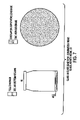
- FIG. 1 is a view of a prior art apparatus wherein a single view is used
- FIG. 2 is a top-view of an apparatus of the present invention having two dual beam x-ray generators on opposite sides of a path of the object to be scanned and each in communication with two detectors opposite their respective x-ray generators;
- FIG. 3 is a view of an apparatus in accordance with the principles of the present invention depicting a first view from a first x-ray apparatus;
- FIG. 4 is a view of an apparatus in accordance with the principles of the present invention depicting a second view from a first x-ray apparatus;
- FIG. 5 is a view of an apparatus in accordance with the principles of the present invention depicting a first view from a second x-ray apparatus;
- FIG. 6 is a view of an apparatus in accordance with the principles of the present invention depicting a second view from a second x-ray apparatus
- FIG. 7 is a view of an apparatus in accordance with the principles of the present invention depicting the composite of the views shown in FIGS. 3–6 .
- system has a structure of two x-ray apparatus 42 a and 42 b oriented on opposite sides of the conveyor 20 traveling through the system. Each apparatus emits a dual beam at 45° from one and other.
- Four x-ray sensor devices 14 a , 14 b , 14 c , 14 d are placed on the opposite side of the conveyor from their respective tube. This inspection structure with two dual beam tubes and four sensors allows substantially 100% inspection of the glass jar bottom.
- FIG. 1 depicts the area of a crown 40 detected by an apparatus of the prior art.
- the prior art apparatus does not provide adequate detection as it is capable of detecting only a small portion of the area below the crown 40 , and the angle of crown creates difficulty in obtaining a clean image of even that area.
- FIG. 3 depicts a first view of a four view (i.e. four beams and detectors) system. This view provides a full coverage of 40% of the jar bottom that is on the detector side of the conveyor.
- the second view shown in FIG. 4 also covers 40% of the jar bottom but is at a 45° angle from the first view and thus shifts the full coverage by 45°. The combination of these two views results in full coverage of 60% of the jar bottom with an overlap between the two views.
- the third view shown in FIG. 5 represents the results of a detector on the opposite side of the conveying line in regard to the detectors shown in FIGS. 3 and 4 .
- This view provides full coverage of 40% of the jar bottom, opposite the first view by changing the tube/detector relationship such that the x-ray beam is shot from the opposite side of the jar. The result is picking up an additional 20% of the jar bottom for full coverage and adding to the overlap.
- the fourth view shown in FIG. 6 adds the final 20% of the jar bottom for full coverage.
- an apparatus and method in accordance with the principles of the present invention may further comprise various additional inspection features such as but not limited to check-weighing capability, missing item detector, void detection, and reject stations.
- the reject station may utilize, but is not limited to, a signal only, an indicator light, a single lane air blast, a single piston side push arm, a vertical side impulse push arm, or a horizontal side impulse push arm.
Abstract
Description
Claims (15)
Priority Applications (3)
| Application Number | Priority Date | Filing Date | Title |
|---|---|---|---|
| US10/875,503 US7164750B2 (en) | 2003-03-26 | 2004-06-25 | Non-destructive inspection of material in container |
| EP05856836A EP1766379A2 (en) | 2004-06-25 | 2005-06-20 | Non-destructive inspection of material in container |
| PCT/US2005/021727 WO2006083302A2 (en) | 2004-06-25 | 2005-06-20 | Non-destructive inspection of material in container |
Applications Claiming Priority (3)
| Application Number | Priority Date | Filing Date | Title |
|---|---|---|---|
| US45731903P | 2003-03-26 | 2003-03-26 | |
| US10/629,868 US6895072B2 (en) | 2003-03-26 | 2003-07-30 | Apparatus and method for non-destructive inspection of material in containers |
| US10/875,503 US7164750B2 (en) | 2003-03-26 | 2004-06-25 | Non-destructive inspection of material in container |
Related Parent Applications (1)
| Application Number | Title | Priority Date | Filing Date |
|---|---|---|---|
| US10/629,868 Continuation-In-Part US6895072B2 (en) | 2003-03-26 | 2003-07-30 | Apparatus and method for non-destructive inspection of material in containers |
Publications (2)
| Publication Number | Publication Date |
|---|---|
| US20050105680A1 US20050105680A1 (en) | 2005-05-19 |
| US7164750B2 true US7164750B2 (en) | 2007-01-16 |
Family
ID=36777655
Family Applications (1)
| Application Number | Title | Priority Date | Filing Date |
|---|---|---|---|
| US10/875,503 Expired - Lifetime US7164750B2 (en) | 2003-03-26 | 2004-06-25 | Non-destructive inspection of material in container |
Country Status (3)
| Country | Link |
|---|---|
| US (1) | US7164750B2 (en) |
| EP (1) | EP1766379A2 (en) |
| WO (1) | WO2006083302A2 (en) |
Cited By (42)
| Publication number | Priority date | Publication date | Assignee | Title |
|---|---|---|---|---|
| US20060257005A1 (en) * | 2005-05-11 | 2006-11-16 | Optosecurity Inc. | Method and system for screening cargo containers |
| US20070041612A1 (en) * | 2005-05-11 | 2007-02-22 | Luc Perron | Apparatus, method and system for screening receptacles and persons, having image distortion correction functionality |
| US20070041613A1 (en) * | 2005-05-11 | 2007-02-22 | Luc Perron | Database of target objects suitable for use in screening receptacles or people and method and apparatus for generating same |
| US20080014643A1 (en) * | 2006-07-12 | 2008-01-17 | Paul Bjorkholm | Dual angle radiation scanning of objects |
| US20080062262A1 (en) * | 2005-05-11 | 2008-03-13 | Luc Perron | Apparatus, method and system for screening receptacles and persons |
| US20080170660A1 (en) * | 2006-05-11 | 2008-07-17 | Dan Gudmundson | Method and apparatus for providing threat image projection (tip) in a luggage screening system, and luggage screening system implementing same |
| US20080240578A1 (en) * | 2007-03-30 | 2008-10-02 | Dan Gudmundson | User interface for use in security screening providing image enhancement capabilities and apparatus for implementing same |
| US20090010382A1 (en) * | 2003-04-25 | 2009-01-08 | Edward James Morton | X-Ray Monitoring |
| US20090060135A1 (en) * | 2005-12-16 | 2009-03-05 | Edward James Morton | X-Ray Tomography Inspection Systems |
| US20090196396A1 (en) * | 2006-10-02 | 2009-08-06 | Optosecurity Inc. | Tray for assessing the threat status of an article at a security check point |
| US20100002834A1 (en) * | 2006-09-18 | 2010-01-07 | Optosecurity Inc | Method and apparatus for assessing characteristics of liquids |
| US20100020927A1 (en) * | 2008-07-24 | 2010-01-28 | Gilevich Alexander I | Apparatus and method for detecting foreign materials in a container |
| US7684538B2 (en) | 2003-04-25 | 2010-03-23 | Rapiscan Systems, Inc. | X-ray scanning system |
| US20100208972A1 (en) * | 2008-09-05 | 2010-08-19 | Optosecurity Inc. | Method and system for performing x-ray inspection of a liquid product at a security checkpoint |
| US20100207741A1 (en) * | 2007-10-10 | 2010-08-19 | Optosecurity Inc. | Method, apparatus and system for use in connection with the inspection of liquid merchandise |
| US20100303287A1 (en) * | 2003-04-25 | 2010-12-02 | Edward James Morton | X-Ray Tomographic Inspection Systems for the Identification of Specific Target Items |
| US20100303329A1 (en) * | 2003-04-25 | 2010-12-02 | Edward James Morton | Imaging, Data Acquisition, Data Transmission, and Data Distribution Methods and Systems for High Data Rate Tomographic X-Ray Scanners |
| US20110007870A1 (en) * | 2007-10-01 | 2011-01-13 | Optosecurity Inc. | Method and devices for assessing the threat status of an article at a security check point |
| US20110019797A1 (en) * | 2003-04-25 | 2011-01-27 | Edward James Morton | X-Ray Tomographic Inspection System for the Identification of Specific Target Items |
| US7949101B2 (en) | 2005-12-16 | 2011-05-24 | Rapiscan Systems, Inc. | X-ray scanners and X-ray sources therefor |
| US20110172972A1 (en) * | 2008-09-15 | 2011-07-14 | Optosecurity Inc. | Method and apparatus for asssessing properties of liquids by using x-rays |
| US8243876B2 (en) | 2003-04-25 | 2012-08-14 | Rapiscan Systems, Inc. | X-ray scanners |
| WO2013185816A1 (en) | 2012-06-13 | 2013-12-19 | Wilco Ag | X-ray detection of flaws in containers and/or in their contents |
| US8831331B2 (en) | 2009-02-10 | 2014-09-09 | Optosecurity Inc. | Method and system for performing X-ray inspection of a product at a security checkpoint using simulation |
| US8837669B2 (en) | 2003-04-25 | 2014-09-16 | Rapiscan Systems, Inc. | X-ray scanning system |
| US8879791B2 (en) | 2009-07-31 | 2014-11-04 | Optosecurity Inc. | Method, apparatus and system for determining if a piece of luggage contains a liquid product |
| US9052403B2 (en) | 2002-07-23 | 2015-06-09 | Rapiscan Systems, Inc. | Compact mobile cargo scanning system |
| US9113839B2 (en) | 2003-04-25 | 2015-08-25 | Rapiscon Systems, Inc. | X-ray inspection system and method |
| US9157873B2 (en) | 2009-06-15 | 2015-10-13 | Optosecurity, Inc. | Method and apparatus for assessing the threat status of luggage |
| US9218933B2 (en) | 2011-06-09 | 2015-12-22 | Rapidscan Systems, Inc. | Low-dose radiographic imaging system |
| US9223049B2 (en) | 2002-07-23 | 2015-12-29 | Rapiscan Systems, Inc. | Cargo scanning system with boom structure |
| US9223052B2 (en) | 2008-02-28 | 2015-12-29 | Rapiscan Systems, Inc. | Scanning systems |
| US9223050B2 (en) | 2005-04-15 | 2015-12-29 | Rapiscan Systems, Inc. | X-ray imaging system having improved mobility |
| US9285498B2 (en) | 2003-06-20 | 2016-03-15 | Rapiscan Systems, Inc. | Relocatable X-ray imaging system and method for inspecting commercial vehicles and cargo containers |
| US9332624B2 (en) | 2008-05-20 | 2016-05-03 | Rapiscan Systems, Inc. | Gantry scanner systems |
| US9429530B2 (en) | 2008-02-28 | 2016-08-30 | Rapiscan Systems, Inc. | Scanning systems |
| US9632206B2 (en) | 2011-09-07 | 2017-04-25 | Rapiscan Systems, Inc. | X-ray inspection system that integrates manifest data with imaging/detection processing |
| US9791590B2 (en) | 2013-01-31 | 2017-10-17 | Rapiscan Systems, Inc. | Portable security inspection system |
| US10254436B2 (en) | 2013-10-01 | 2019-04-09 | Voti Inc. | Scanning system, method, and corresponding bracket |
| US10302807B2 (en) | 2016-02-22 | 2019-05-28 | Rapiscan Systems, Inc. | Systems and methods for detecting threats and contraband in cargo |
| US10845319B2 (en) | 2016-12-14 | 2020-11-24 | Battelle Memorial Institute | Dual-energy microfocus radiographic imaging method for meat inspection |
| US11885752B2 (en) | 2021-06-30 | 2024-01-30 | Rapiscan Holdings, Inc. | Calibration method and device therefor |
Families Citing this family (8)
| Publication number | Priority date | Publication date | Assignee | Title |
|---|---|---|---|---|
| DE20217559U1 (en) * | 2002-11-12 | 2003-01-16 | Heuft Systemtechnik Gmbh | Device for examining filled containers using X-rays |
| US7302033B2 (en) * | 2005-06-29 | 2007-11-27 | Accuray Incorporated | Imaging geometry for image-guided radiosurgery |
| US20070108387A1 (en) * | 2005-11-14 | 2007-05-17 | Xradia, Inc. | Tunable x-ray fluorescence imager for multi-element analysis |
| IL179128A0 (en) * | 2006-11-08 | 2008-01-20 | Traceguard Technologies Ltd | Contaminat scanning system |
| ITMN20070010A1 (en) * | 2007-03-30 | 2008-09-30 | Pe Srl | MACHINE LABELING |
| DE102014117196A1 (en) * | 2014-11-24 | 2016-05-25 | Wipotec Wiege- Und Positioniersysteme Gmbh | Device for X-ray examination of moving products, in particular moving piece goods |
| EP3311148B1 (en) | 2015-06-16 | 2023-06-21 | Dylog Italia S.p.A. | A non-destructive x-ray inspection machine, devices provided for such machine and method for operating the same |
| CN109073572A (en) * | 2016-05-03 | 2018-12-21 | 拉皮斯坎系统股份有限公司 | radiation signal processing system |
Citations (4)
| Publication number | Priority date | Publication date | Assignee | Title |
|---|---|---|---|---|
| US6005912A (en) * | 1996-03-15 | 1999-12-21 | Dylog, Italia, S.P.A. | Non-destructive X-ray inspection apparatus for food industry |
| US20020071520A1 (en) * | 2000-12-13 | 2002-06-13 | Klaus Springer | Apparatus for illuminating objects |
| US6428206B1 (en) * | 1999-02-12 | 2002-08-06 | Kabushiki Kaisha Toshiba | X-ray diagnostic imaging apparatus |
| US20060056583A1 (en) * | 2002-11-12 | 2006-03-16 | Heuft Systemtechnik Gmbh | Device for examining filled containers by means of X-Rays and use of this device |
Family Cites Families (1)
| Publication number | Priority date | Publication date | Assignee | Title |
|---|---|---|---|---|
| US3958078A (en) * | 1974-08-30 | 1976-05-18 | Ithaco, Inc. | X-ray inspection method and apparatus |
-
2004
- 2004-06-25 US US10/875,503 patent/US7164750B2/en not_active Expired - Lifetime
-
2005
- 2005-06-20 EP EP05856836A patent/EP1766379A2/en not_active Withdrawn
- 2005-06-20 WO PCT/US2005/021727 patent/WO2006083302A2/en not_active Application Discontinuation
Patent Citations (4)
| Publication number | Priority date | Publication date | Assignee | Title |
|---|---|---|---|---|
| US6005912A (en) * | 1996-03-15 | 1999-12-21 | Dylog, Italia, S.P.A. | Non-destructive X-ray inspection apparatus for food industry |
| US6428206B1 (en) * | 1999-02-12 | 2002-08-06 | Kabushiki Kaisha Toshiba | X-ray diagnostic imaging apparatus |
| US20020071520A1 (en) * | 2000-12-13 | 2002-06-13 | Klaus Springer | Apparatus for illuminating objects |
| US20060056583A1 (en) * | 2002-11-12 | 2006-03-16 | Heuft Systemtechnik Gmbh | Device for examining filled containers by means of X-Rays and use of this device |
Cited By (98)
| Publication number | Priority date | Publication date | Assignee | Title |
|---|---|---|---|---|
| US9052403B2 (en) | 2002-07-23 | 2015-06-09 | Rapiscan Systems, Inc. | Compact mobile cargo scanning system |
| US10670769B2 (en) | 2002-07-23 | 2020-06-02 | Rapiscan Systems, Inc. | Compact mobile cargo scanning system |
| US10007019B2 (en) | 2002-07-23 | 2018-06-26 | Rapiscan Systems, Inc. | Compact mobile cargo scanning system |
| US9223049B2 (en) | 2002-07-23 | 2015-12-29 | Rapiscan Systems, Inc. | Cargo scanning system with boom structure |
| US9747705B2 (en) | 2003-04-25 | 2017-08-29 | Rapiscan Systems, Inc. | Imaging, data acquisition, data transmission, and data distribution methods and systems for high data rate tomographic X-ray scanners |
| US8243876B2 (en) | 2003-04-25 | 2012-08-14 | Rapiscan Systems, Inc. | X-ray scanners |
| US9618648B2 (en) | 2003-04-25 | 2017-04-11 | Rapiscan Systems, Inc. | X-ray scanners |
| US9442082B2 (en) | 2003-04-25 | 2016-09-13 | Rapiscan Systems, Inc. | X-ray inspection system and method |
| US20090010382A1 (en) * | 2003-04-25 | 2009-01-08 | Edward James Morton | X-Ray Monitoring |
| US9675306B2 (en) | 2003-04-25 | 2017-06-13 | Rapiscan Systems, Inc. | X-ray scanning system |
| US9183647B2 (en) | 2003-04-25 | 2015-11-10 | Rapiscan Systems, Inc. | Imaging, data acquisition, data transmission, and data distribution methods and systems for high data rate tomographic X-ray scanners |
| US10175381B2 (en) | 2003-04-25 | 2019-01-08 | Rapiscan Systems, Inc. | X-ray scanners having source points with less than a predefined variation in brightness |
| US11796711B2 (en) | 2003-04-25 | 2023-10-24 | Rapiscan Systems, Inc. | Modular CT scanning system |
| US9113839B2 (en) | 2003-04-25 | 2015-08-25 | Rapiscon Systems, Inc. | X-ray inspection system and method |
| US7684538B2 (en) | 2003-04-25 | 2010-03-23 | Rapiscan Systems, Inc. | X-ray scanning system |
| US7724868B2 (en) | 2003-04-25 | 2010-05-25 | Rapiscan Systems, Inc. | X-ray monitoring |
| US20110019797A1 (en) * | 2003-04-25 | 2011-01-27 | Edward James Morton | X-Ray Tomographic Inspection System for the Identification of Specific Target Items |
| US8885794B2 (en) | 2003-04-25 | 2014-11-11 | Rapiscan Systems, Inc. | X-ray tomographic inspection system for the identification of specific target items |
| US10591424B2 (en) | 2003-04-25 | 2020-03-17 | Rapiscan Systems, Inc. | X-ray tomographic inspection systems for the identification of specific target items |
| US20100303295A1 (en) * | 2003-04-25 | 2010-12-02 | Edward James Morton | X-Ray Monitoring |
| US20100303287A1 (en) * | 2003-04-25 | 2010-12-02 | Edward James Morton | X-Ray Tomographic Inspection Systems for the Identification of Specific Target Items |
| US20100303329A1 (en) * | 2003-04-25 | 2010-12-02 | Edward James Morton | Imaging, Data Acquisition, Data Transmission, and Data Distribution Methods and Systems for High Data Rate Tomographic X-Ray Scanners |
| US8837669B2 (en) | 2003-04-25 | 2014-09-16 | Rapiscan Systems, Inc. | X-ray scanning system |
| US9020095B2 (en) | 2003-04-25 | 2015-04-28 | Rapiscan Systems, Inc. | X-ray scanners |
| US10901112B2 (en) | 2003-04-25 | 2021-01-26 | Rapiscan Systems, Inc. | X-ray scanning system with stationary x-ray sources |
| US7929663B2 (en) | 2003-04-25 | 2011-04-19 | Rapiscan Systems, Inc. | X-ray monitoring |
| US8804899B2 (en) | 2003-04-25 | 2014-08-12 | Rapiscan Systems, Inc. | Imaging, data acquisition, data transmission, and data distribution methods and systems for high data rate tomographic X-ray scanners |
| US8451974B2 (en) | 2003-04-25 | 2013-05-28 | Rapiscan Systems, Inc. | X-ray tomographic inspection system for the identification of specific target items |
| US8223919B2 (en) | 2003-04-25 | 2012-07-17 | Rapiscan Systems, Inc. | X-ray tomographic inspection systems for the identification of specific target items |
| US9285498B2 (en) | 2003-06-20 | 2016-03-15 | Rapiscan Systems, Inc. | Relocatable X-ray imaging system and method for inspecting commercial vehicles and cargo containers |
| US9223050B2 (en) | 2005-04-15 | 2015-12-29 | Rapiscan Systems, Inc. | X-ray imaging system having improved mobility |
| US7991242B2 (en) | 2005-05-11 | 2011-08-02 | Optosecurity Inc. | Apparatus, method and system for screening receptacles and persons, having image distortion correction functionality |
| US20080062262A1 (en) * | 2005-05-11 | 2008-03-13 | Luc Perron | Apparatus, method and system for screening receptacles and persons |
| US7734102B2 (en) | 2005-05-11 | 2010-06-08 | Optosecurity Inc. | Method and system for screening cargo containers |
| US20070058037A1 (en) * | 2005-05-11 | 2007-03-15 | Optosecurity Inc. | User interface for use in screening luggage, containers, parcels or people and apparatus for implementing same |
| US20060257005A1 (en) * | 2005-05-11 | 2006-11-16 | Optosecurity Inc. | Method and system for screening cargo containers |
| US20070041612A1 (en) * | 2005-05-11 | 2007-02-22 | Luc Perron | Apparatus, method and system for screening receptacles and persons, having image distortion correction functionality |
| US20070041613A1 (en) * | 2005-05-11 | 2007-02-22 | Luc Perron | Database of target objects suitable for use in screening receptacles or people and method and apparatus for generating same |
| US20090060135A1 (en) * | 2005-12-16 | 2009-03-05 | Edward James Morton | X-Ray Tomography Inspection Systems |
| US8135110B2 (en) | 2005-12-16 | 2012-03-13 | Rapiscan Systems, Inc. | X-ray tomography inspection systems |
| US9048061B2 (en) | 2005-12-16 | 2015-06-02 | Rapiscan Systems, Inc. | X-ray scanners and X-ray sources therefor |
| US10976271B2 (en) | 2005-12-16 | 2021-04-13 | Rapiscan Systems, Inc. | Stationary tomographic X-ray imaging systems for automatically sorting objects based on generated tomographic images |
| US8625735B2 (en) | 2005-12-16 | 2014-01-07 | Rapiscan Systems, Inc. | X-ray scanners and X-ray sources therefor |
| US10295483B2 (en) | 2005-12-16 | 2019-05-21 | Rapiscan Systems, Inc. | Data collection, processing and storage systems for X-ray tomographic images |
| US7949101B2 (en) | 2005-12-16 | 2011-05-24 | Rapiscan Systems, Inc. | X-ray scanners and X-ray sources therefor |
| US8958526B2 (en) | 2005-12-16 | 2015-02-17 | Rapiscan Systems, Inc. | Data collection, processing and storage systems for X-ray tomographic images |
| US9638646B2 (en) | 2005-12-16 | 2017-05-02 | Rapiscan Systems, Inc. | X-ray scanners and X-ray sources therefor |
| US7899232B2 (en) | 2006-05-11 | 2011-03-01 | Optosecurity Inc. | Method and apparatus for providing threat image projection (TIP) in a luggage screening system, and luggage screening system implementing same |
| US20080170660A1 (en) * | 2006-05-11 | 2008-07-17 | Dan Gudmundson | Method and apparatus for providing threat image projection (tip) in a luggage screening system, and luggage screening system implementing same |
| US8137976B2 (en) | 2006-07-12 | 2012-03-20 | Varian Medical Systems, Inc. | Dual angle radiation scanning of objects |
| US20080014643A1 (en) * | 2006-07-12 | 2008-01-17 | Paul Bjorkholm | Dual angle radiation scanning of objects |
| US8551785B2 (en) | 2006-07-12 | 2013-10-08 | Varian Medical Systems, Inc. | Dual angle radiation scanning of objects |
| US8116428B2 (en) | 2006-09-18 | 2012-02-14 | Optosecurity Inc. | Method and apparatus for assessing characteristics of liquids |
| US8781066B2 (en) | 2006-09-18 | 2014-07-15 | Optosecurity Inc. | Method and apparatus for assessing characteristics of liquids |
| US20100002834A1 (en) * | 2006-09-18 | 2010-01-07 | Optosecurity Inc | Method and apparatus for assessing characteristics of liquids |
| US8009799B2 (en) | 2006-10-02 | 2011-08-30 | Optosecurity Inc. | Tray for use in assessing the threat status of an article at a security check point |
| US20100027741A1 (en) * | 2006-10-02 | 2010-02-04 | Aidan Doyle | Tray for assessing the threat status of an article at a security check point |
| US20090196396A1 (en) * | 2006-10-02 | 2009-08-06 | Optosecurity Inc. | Tray for assessing the threat status of an article at a security check point |
| US8009800B2 (en) | 2006-10-02 | 2011-08-30 | Optosecurity Inc. | Tray for assessing the threat status of an article at a security check point |
| US8494210B2 (en) | 2007-03-30 | 2013-07-23 | Optosecurity Inc. | User interface for use in security screening providing image enhancement capabilities and apparatus for implementing same |
| US20080240578A1 (en) * | 2007-03-30 | 2008-10-02 | Dan Gudmundson | User interface for use in security screening providing image enhancement capabilities and apparatus for implementing same |
| US20110007870A1 (en) * | 2007-10-01 | 2011-01-13 | Optosecurity Inc. | Method and devices for assessing the threat status of an article at a security check point |
| US8014493B2 (en) | 2007-10-01 | 2011-09-06 | Optosecurity Inc. | Method and devices for assessing the threat status of an article at a security check point |
| US20100207741A1 (en) * | 2007-10-10 | 2010-08-19 | Optosecurity Inc. | Method, apparatus and system for use in connection with the inspection of liquid merchandise |
| US10585207B2 (en) | 2008-02-28 | 2020-03-10 | Rapiscan Systems, Inc. | Scanning systems |
| US9223052B2 (en) | 2008-02-28 | 2015-12-29 | Rapiscan Systems, Inc. | Scanning systems |
| US11768313B2 (en) | 2008-02-28 | 2023-09-26 | Rapiscan Systems, Inc. | Multi-scanner networked systems for performing material discrimination processes on scanned objects |
| US11275194B2 (en) | 2008-02-28 | 2022-03-15 | Rapiscan Systems, Inc. | Scanning systems |
| US9429530B2 (en) | 2008-02-28 | 2016-08-30 | Rapiscan Systems, Inc. | Scanning systems |
| US10098214B2 (en) | 2008-05-20 | 2018-10-09 | Rapiscan Systems, Inc. | Detector support structures for gantry scanner systems |
| US9332624B2 (en) | 2008-05-20 | 2016-05-03 | Rapiscan Systems, Inc. | Gantry scanner systems |
| US20100020927A1 (en) * | 2008-07-24 | 2010-01-28 | Gilevich Alexander I | Apparatus and method for detecting foreign materials in a container |
| US7970102B2 (en) | 2008-07-24 | 2011-06-28 | Inspx Llc | Apparatus and method for detecting foreign materials in a container |
| US20100208972A1 (en) * | 2008-09-05 | 2010-08-19 | Optosecurity Inc. | Method and system for performing x-ray inspection of a liquid product at a security checkpoint |
| US9170212B2 (en) | 2008-09-05 | 2015-10-27 | Optosecurity Inc. | Method and system for performing inspection of a liquid product at a security checkpoint |
| US8867816B2 (en) | 2008-09-05 | 2014-10-21 | Optosecurity Inc. | Method and system for performing X-ray inspection of a liquid product at a security checkpoint |
| US20110172972A1 (en) * | 2008-09-15 | 2011-07-14 | Optosecurity Inc. | Method and apparatus for asssessing properties of liquids by using x-rays |
| US8831331B2 (en) | 2009-02-10 | 2014-09-09 | Optosecurity Inc. | Method and system for performing X-ray inspection of a product at a security checkpoint using simulation |
| US9157873B2 (en) | 2009-06-15 | 2015-10-13 | Optosecurity, Inc. | Method and apparatus for assessing the threat status of luggage |
| US8879791B2 (en) | 2009-07-31 | 2014-11-04 | Optosecurity Inc. | Method, apparatus and system for determining if a piece of luggage contains a liquid product |
| US9194975B2 (en) | 2009-07-31 | 2015-11-24 | Optosecurity Inc. | Method and system for identifying a liquid product in luggage or other receptacle |
| US9218933B2 (en) | 2011-06-09 | 2015-12-22 | Rapidscan Systems, Inc. | Low-dose radiographic imaging system |
| US11099294B2 (en) | 2011-09-07 | 2021-08-24 | Rapiscan Systems, Inc. | Distributed analysis x-ray inspection methods and systems |
| US10509142B2 (en) | 2011-09-07 | 2019-12-17 | Rapiscan Systems, Inc. | Distributed analysis x-ray inspection methods and systems |
| US10422919B2 (en) | 2011-09-07 | 2019-09-24 | Rapiscan Systems, Inc. | X-ray inspection system that integrates manifest data with imaging/detection processing |
| US10830920B2 (en) | 2011-09-07 | 2020-11-10 | Rapiscan Systems, Inc. | Distributed analysis X-ray inspection methods and systems |
| US9632206B2 (en) | 2011-09-07 | 2017-04-25 | Rapiscan Systems, Inc. | X-ray inspection system that integrates manifest data with imaging/detection processing |
| US9278378B2 (en) | 2012-06-13 | 2016-03-08 | Wilco Ag | X-ray detection of flaws in containers and/or in their contents |
| WO2013185816A1 (en) | 2012-06-13 | 2013-12-19 | Wilco Ag | X-ray detection of flaws in containers and/or in their contents |
| US9791590B2 (en) | 2013-01-31 | 2017-10-17 | Rapiscan Systems, Inc. | Portable security inspection system |
| US10317566B2 (en) | 2013-01-31 | 2019-06-11 | Rapiscan Systems, Inc. | Portable security inspection system |
| US11550077B2 (en) | 2013-01-31 | 2023-01-10 | Rapiscan Systems, Inc. | Portable vehicle inspection portal with accompanying workstation |
| US10254436B2 (en) | 2013-10-01 | 2019-04-09 | Voti Inc. | Scanning system, method, and corresponding bracket |
| US10768338B2 (en) | 2016-02-22 | 2020-09-08 | Rapiscan Systems, Inc. | Systems and methods for detecting threats and contraband in cargo |
| US10302807B2 (en) | 2016-02-22 | 2019-05-28 | Rapiscan Systems, Inc. | Systems and methods for detecting threats and contraband in cargo |
| US11287391B2 (en) | 2016-02-22 | 2022-03-29 | Rapiscan Systems, Inc. | Systems and methods for detecting threats and contraband in cargo |
| US10845319B2 (en) | 2016-12-14 | 2020-11-24 | Battelle Memorial Institute | Dual-energy microfocus radiographic imaging method for meat inspection |
| US11885752B2 (en) | 2021-06-30 | 2024-01-30 | Rapiscan Holdings, Inc. | Calibration method and device therefor |
Also Published As
| Publication number | Publication date |
|---|---|
| WO2006083302A2 (en) | 2006-08-10 |
| US20050105680A1 (en) | 2005-05-19 |
| WO2006083302A3 (en) | 2007-02-08 |
| EP1766379A2 (en) | 2007-03-28 |
Similar Documents
| Publication | Publication Date | Title |
|---|---|---|
| US7164750B2 (en) | Non-destructive inspection of material in container | |
| US6151381A (en) | Gated transmission and scatter detection for x-ray imaging | |
| US6914678B1 (en) | Inspection of matter | |
| US6269142B1 (en) | Interrupted-fan-beam imaging | |
| US5260982A (en) | Scattered radiation imaging apparatus | |
| RU2444723C2 (en) | Apparatus and method of inspecting objects | |
| WO1997037359A1 (en) | Sidescatter x-ray detection system | |
| JP2005534009A (en) | Radiation scanning of objects on contraband | |
| JPH1082747A (en) | Square traverse ct detection method | |
| GB2219394A (en) | Sorting diamond bearing ore | |
| IL158190A (en) | X-ray inspection system | |
| US7106827B2 (en) | Device for examining filled containers by means of X-rays and use of this device | |
| CA2283519C (en) | Device for detecting diffusely scattered impurities in transparent receptacles | |
| JPS6367552A (en) | X-ray inspection instrument | |
| US20210370352A1 (en) | Detecting non-handleable items | |
| CN1723388A (en) | Radiographic equipment | |
| EP0795746B1 (en) | Non-destructive X-ray inspection apparatus for food industry | |
| EP1287341B1 (en) | X-ray inspection method for food containers | |
| US6005912A (en) | Non-destructive X-ray inspection apparatus for food industry | |
| US5467125A (en) | Apparatus for the inspection of transparent containers | |
| EP1051609B1 (en) | Gated transmission and scatter detection for x-ray imaging | |
| WO2022044430A1 (en) | Foreign matter inspection device | |
| JP2005121468A (en) | Food foreign substance inspection device for hair or the like using fluorescent x-ray |
Legal Events
| Date | Code | Title | Description |
|---|---|---|---|
| AS | Assignment |
Owner name: SMITHS DETECTION INC., MARYLAND Free format text: ASSIGNMENT OF ASSIGNORS INTEREST;ASSIGNORS:NABORS, JAMES;NASH, BROOK;SCHROCK, TODD;AND OTHERS;REEL/FRAME:016163/0532;SIGNING DATES FROM 20041015 TO 20050118 |
|
| STCF | Information on status: patent grant |
Free format text: PATENTED CASE |
|
| FPAY | Fee payment |
Year of fee payment: 4 |
|
| AS | Assignment |
Owner name: METTLER-TOLEDO, INC., OHIO Free format text: ASSIGNMENT OF ASSIGNORS INTEREST;ASSIGNOR:SMITHS DETECTION INC.;REEL/FRAME:028979/0134 Effective date: 20110318 Owner name: METTLER-TOLEDO, LLC, OHIO Free format text: ENTITY CONVERSION AND CHANGE OF NAME;ASSIGNOR:METTLER-TOLEDO, INC.;REEL/FRAME:029003/0046 Effective date: 20111207 |
|
| FPAY | Fee payment |
Year of fee payment: 8 |
|
| MAFP | Maintenance fee payment |
Free format text: PAYMENT OF MAINTENANCE FEE, 12TH YEAR, LARGE ENTITY (ORIGINAL EVENT CODE: M1553) Year of fee payment: 12 |