US7063532B1 - Subdividing a digital dentition model - Google Patents
Subdividing a digital dentition model Download PDFInfo
- Publication number
- US7063532B1 US7063532B1 US09/264,547 US26454799A US7063532B1 US 7063532 B1 US7063532 B1 US 7063532B1 US 26454799 A US26454799 A US 26454799A US 7063532 B1 US7063532 B1 US 7063532B1
- Authority
- US
- United States
- Prior art keywords
- dentition
- cross
- data elements
- sectional surface
- computer
- Prior art date
- Legal status (The legal status is an assumption and is not a legal conclusion. Google has not performed a legal analysis and makes no representation as to the accuracy of the status listed.)
- Expired - Fee Related
Links
Images


Classifications
-
- A—HUMAN NECESSITIES
- A61—MEDICAL OR VETERINARY SCIENCE; HYGIENE
- A61C—DENTISTRY; APPARATUS OR METHODS FOR ORAL OR DENTAL HYGIENE
- A61C7/00—Orthodontics, i.e. obtaining or maintaining the desired position of teeth, e.g. by straightening, evening, regulating, separating, or by correcting malocclusions
-
- A—HUMAN NECESSITIES
- A61—MEDICAL OR VETERINARY SCIENCE; HYGIENE
- A61C—DENTISTRY; APPARATUS OR METHODS FOR ORAL OR DENTAL HYGIENE
- A61C9/00—Impression cups, i.e. impression trays; Impression methods
- A61C9/004—Means or methods for taking digitized impressions
-
- A—HUMAN NECESSITIES
- A61—MEDICAL OR VETERINARY SCIENCE; HYGIENE
- A61C—DENTISTRY; APPARATUS OR METHODS FOR ORAL OR DENTAL HYGIENE
- A61C9/00—Impression cups, i.e. impression trays; Impression methods
- A61C9/004—Means or methods for taking digitized impressions
- A61C9/0046—Data acquisition means or methods
- A61C9/0053—Optical means or methods, e.g. scanning the teeth by a laser or light beam
Definitions
- the invention relates generally to the fields of dentistry and orthodontics and, more particularly, to subdividing a digital model of a patient's dentition.
- Two-dimensional (2D) and three-dimensional (3D) digital image technology has recently been tapped as a tool to assist in dental and orthodontic treatment.
- Many treatment providers use some form of digital image technology to study the dentitions of patients.
- U.S. patent application Ser. No. 09/169,276, incorporated by reference above describes the use of 2D and 3D image data in forming a digital model of a patient's dentition, including models of individual dentition components. Such models are useful, among other things, in developing an orthodontic treatment plan for the patient, as well as in creating one or more orthodontic appliances to implement the treatment plan.
- a computer implementing the invention receives a data set that forms a three-dimensional (3D) representation of the patient's dentition, applies a test to the data set to identify data elements that represent portions of the individual component, and creates a digital model of the individual component based upon the identified data elements.
- Some implementations require the computer to identify data elements that form one or more 2D cross-sections of the dentition in one or more 2D planes intersecting the dentition. In many of these embodiments, these 2D planes are roughly parallel to the dentition's occlusal plane.
- the computer analyzes the features of the 2D cross-sections to identify data elements that correspond to the individual component to be modeled.
- one technique requires the computer to identify cusps in the 2D cross-sectional surface of the dentition, where the cusps represent the locations of an interproximal margin between teeth in the dentition.
- One variation of this technique allows the computer to confine its search for cusps in one 2D plane to areas in the vicinity of cusps already identified on another 2D plane.
- Another variation allows the computer to link cusps on adjacent 2D planes to form a solid surface representing the interproximal margin.
- Some embodiments allow the computer to receive input from a human user identifying the cusp locations in one or more of the 2D cross sections.
- a computer implementing the invention receives a three-dimensional (3D) data set representing the patient's dentition, applies a test to identify data elements that represent an interproximal margin between two teeth in the dentition, and applies another computer-implemented test to select data elements that lie on one side of the interproximal margin for inclusion in the digital model.
- Some implementations require the computer to identify data elements that form one or more 2D cross-sections of the dentition in one or more 2D planes intersecting the dentition roughly parallel to the dentition's occlusal plane.
- a computer implementing the invention receives a 3D data set representing at least a portion of the patient's dentition, including at least a portion of a tooth and gum tissue surrounding the tooth; applies a test to identify data elements lying on a gingival boundary that occurs where the tooth and the gum tissue meet; and applies a test to the data elements lying on the boundary to identify other data elements representing portions of the tooth.
- FIGS. 1A , 1 B, and 2 are partial views of a dentition model as displayed on a computer monitor and segmented with a human operated saw tool.
- FIG. 3 is a partial view of a dentition model as displayed on a computer monitor and segmented with a human operated eraser tool.
- FIG. 4 is a view of a dentition model for which a feature skeleton has been identified.
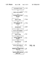
- FIGS. 5 and 6 are flow diagram for a feature skeleton analysis technique used in segmenting a dentition model.
- FIG. 8 is a flow diagram for a 2D slice analysis technique used in segmenting a dentition model.
- FIGS. 9 and 10A through 10 C each shows a group of voxels in a 2D slice of a dentition model.
- FIG. 11 is a flow chart for an automatic cusp detection technique used in segmenting a dentition model.
- FIG. 12 is a horizontal 2D cross-section of a dentition model illustrating a neighborhood filtered automatic cusp detection technique used in segmenting the dentition model.
- FIG. 13 is shows two groups of voxels in a 2D slice of a dentition model illustrating the neighborhood filtered automatic cusp detection technique.
- FIG. 15 is a horizontal 2D cross-section of a dentition model illustrating an arch curve fitting technique used in segmenting the dentition model.
- FIG. 17 is a horizontal 2D cross-section of a dentition model illustrating a curve creation technique for use with the arch curve fitting technique.
- FIG. 18 is a flow diagram for the curve creation technique.
- FIGS. 20 and 21 are flow diagrams of this technique.
- FIG. 22 is a vertical 2D cross-sectional view of a dentition model illustrating a gingival margin detection technique for use in segmenting the dentition model.
- FIG. 24 is a flow diagram for the gingival margin detection technique.
- U.S. patent application Ser. No. 09/169,276 describes techniques for generating a 3D digital model of a patient's dentition, including the crowns and roots of the patients teeth as well as the surrounding gum tissue.
- One such technique involves creating a physical model of the dentition from a material such as plaster and then digitally imaging the model with a laser scanner or a destructive scanning system.
- the described techniques are used to produce a volumetric 3D image model (“volume element representation” or “voxel representation”) and a geometric 3D surface model (“geometric model”) of the dentition.
- volume element representation or “voxel representation”
- geometric 3D surface model (“geometric model”
- the physical model is usually embedded in a potting material that contrasts sharply with the color of the model to enhance detection of the dentition features.
- a white dentition model embedded in a black potting material provides the sharpest contrast.
- a wide variety of information is used to enhance the 3D model, including data taken from photographic images, 2D and 3D x-rays scans, computed tomography (CT) scans, and magnetic resonance imaging (MRI) scans of the patient's dentition.
- Some computer-implemented techniques for segmenting a 3D dentition model into models of individual dentition components require a substantial amount of human interaction with the computer.
- One such technique which is shown in FIGS. 1A , 1 B, and 2 , provides a graphical user interface with a feature that imitates a conventional saw, allowing the user to identify components to be cut away from the dentition model 100 .
- the graphical user interface provides a rendered 3D image 100 of the dentition model, either at one or more static views from predetermined positions, as shown in FIGS. 1A and 1B , or in a “full 3D” mode that allows the user to alter the viewing angle, as shown in FIG. 2 .
- the user identifies portions of the dentition model for removal by manipulating a graphical representation 110 of the 3D solid with an input device.
- the computer either removes the identified portions of the dentition model as the user moves the eraser 112 , or the computer waits until the user stops moving the eraser and provides an instruction to remove the identified portions.
- the computer updates the display in real time to show the path 114 of the eraser through the dentition model.
- FIG. 4 Another computer-implemented segmentation techniques require little or no human interaction during the segmentation process.
- One such technique involves the application of conventional “feature skeleton” analysis to a volumetric representation of the dentition model. This technique is particularly useful in identifying and modeling individual teeth.
- a computer applying this technique identifies a core of voxels, that forms a skeleton 122 for the dentition 120 .
- the skeleton 122 roughly resembles the network of biological nerves within patient's teeth.
- the computer then divides the skeleton 122 into branches 124 , each containing voxels that lie entirely within one tooth.
- One technique for identifying the branches is by defining a plane 126 that cuts through the skeleton 122 roughly parallel to the occlusal plane of the patient's dentition (“horizontal plane”). Each branch 124 intersects the horizontal plane 126 at one or more points, or clusters, that are relatively distant from the clusters associated with the other branches.
- the computer forms the individual tooth models by linking other voxels to the appropriate branches 124 of the skeleton.
- the computer uses the skeleton to divide the dentition model into 3D models of the individual teeth.
- FIG. 6 shows one technique for doing so.
- the computer first identifies those portions of the skeleton that are associated with each individual tooth. To do so, the computer defines a plane that is roughly parallel to the dentition's occlusal surface and that intersects the skeleton near its base (step 136 ). The computer then identifies points at which the plane and the skeleton intersect by identifying each voxel that lies on both the skeleton and the plane (step 138 ).
- a single tooth includes all of the voxels that lie in a particular branch of the skeleton; and because the plane intersects the skeleton near its base, voxels that lie together in a branch of the skeleton usually cluster together on the intersecting plane.
- the computer is able to locate the branches by identifying voxels on the skeleton that lie within a particular distance of each other on the intersecting plane (step 140 ).
- the computer then identifies and labels all voxels on the skeleton that belong to each branch (step 142 ).
- the computer links other voxels in the model to the branches.
- the computer begins by identifying a reference voxel in each branch of the skeleton (step 144 ). For each reference voxel, the computer selects an adjacent voxel that does not lie on the skeleton (step 146 ).
- the computer Upon testing all adjacent voxels, the computer selects one of the adjacent voxels as a new reference point, provided that the adjacent voxel is labeled as belonging to the same tooth, and then repeats the test above for each untested voxel that is adjacent to the new reference point. This process continues until all voxels in the dentition have been tested.
- FIGS. 7A and 7B illustrate another technique for identifying and segmenting individual teeth in the dentition model.
- This technique called “2D slice analysis,” involves dividing the voxel representation of the dentition model into a series of parallel 2D planes 160 , or slices, that are each one voxel thick and that are roughly parallel to the dentition's occlusal plane.
- Each of the 2D slices 160 includes a 2D cross-section 162 of the dentition, the surface 164 of which represents the lingual and buccal surfaces of the patient's teeth and/or gums.
- the computer inspects the cross-section 162 in each 2D slice 160 to identify voxels that approximate the locations of the interproximal margins 166 between the teeth.
- voxels lie at the tips of cusps 165 in the 2D cross-sectional surface 164 .
- the computer uses the identified voxels to create 3D surfaces 168 intersecting the dentition model at these locations.
- the computer segments the dentition model along these intersecting surfaces 168 to create individual tooth models.
- the computer calculates the rate of curvature (i.e., the derivative of the radius of curvature) at each voxel on the 2D cross-sectional surface 164 (step 176 ) and identifies all of the voxels at which local maxima in the rate of curvature occur (step 178 ).
- Each voxel at which a local maximum occurs represents a “cusp” in the 2D cross-sectional surface 164 and roughly coincides with an interproximal margin between teeth.
- the computer identifies pairs of these cusp voxels that correspond to the same interproximal margin (step 180 ), and the computer labels each pair to identify the interproximal margin with which it is associated (step 182 ).
- FIG. 9 illustrates one technique for creating the 3D surfaces that approximate the interproximal margins.
- the computer For each pair of cusp voxels 190 a-b in a 2D slice that are associated with a particular interproximal region, the computer creates a line segment 192 bounded by these cusp voxels 190 a-b .
- the computer changes the colors of the voxels in the line segment, including the cusp voxels 190 a-b that bound the segment, to contrast with the other voxels in the 2D slice.
- the computer creates line segments in this manner in each successive 2D slice, forming 3D surfaces that represent the interproximal regions. All of the voxels that lie between adjacent ones of these 3D surfaces represent an individual tooth.
- the computer eliminates these discontinuities by creating two new line segments 212 , 214 , each of which is bounded by one cusp voxel 202 a-b , 204 a-b from each original line segment 200 , 206 , as shown in FIG. 10 B.
- the computer then eliminates the islands between the new line segments 212 , 214 by changing the colors of all voxels between the new line segments 212 , 214 , as shown in FIG. 10 C.
- seed cusp detection refers to a location at which an interproximal margin meets the patient's gum tissue.
- seed cusp refers to a location at which an interproximal margin meets the patient's gum tissue.
- a seed cusp for a particular interproximal margin is found at the cusp voxel that lies closest to the gumline.
- FIG. 11 shows a particular implementation of the seed cusp detection technique, in which the computer detects the seed cusps by identifying each 2D slice in which the rate of curvature of a cusp first falls below a predetermined threshold value.
- the computer begins by selecting a 2D slice that intersects all of the teeth in the arch (step 220 ).
- the computer attempts to select a slice that is near the gingival regions but that does not include any voxels representing gingival tissue.
- the computer then identifies all of the cusp voxels in the 2D slice (step 222 ).
- FIGS. 12 , 13 , and 14 illustrate a technique, known as “neighborhood-filtered cusp detection,” by which the computer focuses its search for cusps on one 2D slice to neighborhoods 244 , 246 of voxels defined by a pair of previously detected cusp voxels 240 , 242 on another 2D slice.
- the computer Upon detecting a pair of cusp voxels 240 , 242 in a 2D slice at level N (step 250 ), the computer defines one or more neighborhoods 244 , 246 that include a predetermined number of voxels surrounding the pair (step 252 ).
- the computer In searching for the cusp voxels on the N+1 slice, the computer tests the image values for all voxels in the projected neighborhoods to identify those associated with the background image and those associated with the dentition (step 256 ). In the illustrated example, voxels in the background are black and voxels in the dentition are white. The computer identifies the cusp voxels on the N+1 slice by locating the pair of black voxels in the two neighborhoods that lie closest together (step 258 ). The computer then repeats this process for all remaining slices (step 259 ).
- FIGS. 15 and 16 illustrate another technique, known as “arch curve fitting,” for identifying interproximal margins between teeth in the dentition.
- the arch curve fitting technique which also applies to 2D cross-sectional slices of the dentition, involves the creation of a curve 260 that fits among the voxels on the 2D cross-sectional surface 262 of the dentition arch 264 .
- a series of closely-spaced line segments 268 are formed along the curve 260 , roughly perpendicular to the curve 260 , throughout the 2D cross-section 264 .
- the shortest of these line segments 268 lie on or near the interproximal margins; thus computer identifies the cusps that define the interproximal margins by determining the relative lengths of the line segments 268 .
- the computer calculates the length of each line segment (step 278 ) and then identifies those line segments that form local minima in length (step 280 ). These line segments roughly approximate the locations of the interproximal boundaries, and the computer labels the voxels that bound these segments as cusp voxels (step 282 ). The computer repeats this process for each of the 2D slices (step 284 ) and then uses the cusp voxels to define 3D cutting surfaces that approximate the interproximal margins.
- the computer refines the arch cusp determination by creating several additional sets of line segments, each centered around the arch cusps identified on the first pass.
- the line segments are spaced more narrowly on this pass to provide greater resolution in identifying the actual positions of the arch cusps.
- the computer uses any of a variety of curve fitting techniques to create the curve through the arch.
- One technique involves the creation of a catenary curve with endpoints lying at the two ends 265 , 267 ( FIG. 15 ) of the arch.
- Another technique involves the creation of two curves, one fitted among voxels lying on the front surface 271 of the arch, and the other fitted among voxels on the rear surface 273 .
- a third curve which guides the placement of the line segments above, passes through the middle of the area lying between the first two curves.
- the computer first locates an end 265 of the arch (step 300 ) and creates a line segment 291 that passes through the arch 264 near this end 265 (step 301 ).
- the line segment 291 is bounded by voxels 292 a-b lying on the surface of the arch.
- the computer determines the midpoint 293 of the line segment 291 (step 302 ), selects a voxel 294 located particular distance from the midpoint 293 (step 304 ), and creates a second line segment 295 that is parallel to the initial line segment 291 and that includes the selected voxel 294 (step 306 ).
- the computer then calculates the midpoint 296 of the second segment 295 (step 308 ) and rotates the second segment 295 to the orientation 295 ′ that gives the segment its minimum possible length (step 309 ). In some cases, the computer limits the second segment 295 to a predetermined amount of rotation (e.g., ⁇ 10°).
- FIGS. 19A , 19 B and 20 illustrate an alternative technique for creating 3D surfaces that approximate the geometries and locations of the interproximal margins in the patient's dentition.
- This technique involves the creation of 2D planes that intersect the 3D dentition model at locations that approximate the interproximal margins.
- the computer defines a series of planes, beginning with an initial plane 330 at one end 331 of the arch 332 , that are roughly perpendicular to the occlusal plane of the dentition model (“vertical” planes). Each plane intersects the dentition model to form a 2D cross-section 334 .
- the computer first identifies one end of the arch in the dentition model (step 340 ).
- the computer then creates a vertical plane 330 through the arch near this end (step 342 ) and identifies the centerpoint 331 of the plane 330 (step 344 ).
- the computer selects a voxel located a predetermined distance from the centerpoint (step 345 ) and creates a second plane 333 that is parallel to the initial plane and that includes the selected voxel (step 346 ).
- the computer calculates the midpoint of the second plane (step 348 ) and rotates the second plane about two orthogonal axes that intersect at the midpoint (step 350 ).
- FIGS. 22 , 23 , and 24 illustrate a technique for identifying the gingival margin that defines the boundary between tooth and gum in the patient's dentition. This technique involves the creation of a series of horizontal 2D planes 380 , or slices, that intersect the dentition model roughly perpendicular to the occlusal plane (see FIG. 19 A).
- the cross-sectional surface 382 of the dentition model in each of these planes 380 includes cusps 384 , 386 that represent the gingival margin.
- the computer identifies the gingival margin by applying one or more of the cusp detection techniques described above.
- voxel neighborhoods 388 , 390 are defined on one of the 2D planes to focus the computer's search for cusps on an adjacent 2D plane.
- the computer Upon detecting a pair of cusps 384 , 386 on one 2D plane (step 400 ), the computer defines one or more neighborhoods 388 , 390 to include a predetermined number of voxels surrounding the pair (step 402 ).
- the computer projects the neighborhoods onto an adjacent 2D plane by identifying the voxels on the adjacent plane that correspond to the voxels in the neighborhoods 388 , 390 on the original plane (step 404 ).
- the computer then identifies the pair of black voxels that lie closest together in the two neighborhoods on the adjacent plane, labeling these voxels as lying in the cusp (step 406 ). The computer repeats this process for all remaining planes (step 408 ).
- the computer creates proposals for segmenting the dentition model and then allows the user to select the best alternative.
- one version of the arch curve fitting technique requires the computer to create a candidate catenary or spline curve, which the user is allowed to modify by manipulating the mathematical control parameters.
- Other techniques involve displaying several surfaces that are candidate cutting surfaces and allowing the user to select the appropriate surfaces.
- Some implementations of the invention are realized in digital electronic circuitry, such as an application specific integrated circuit (ASIC); others are realized in computer hardware, firmware, and software, or in combinations of digital circuitry and computer components.
- the invention is usually embodied, at least in part, as a computer program tangibly stored in a machine-readable storage device for execution by a computer processor. In these situations, methods embodying the invention are performed when the processor executes instructions organized into program modules, operating on input data and generating output.
- Suitable processors include general and special purpose microprocessors, which generally receive instructions and data from read-only memory and/or random access memory devices.
- Storage devices that are suitable for tangibly embodying computer program instructions include all forms of non-volatile memory, including semiconductor memory devices, such as EPROM, EEPROM, and flash memory devices; magnetic disks such as internal hard disks and removable disks; magneto-optical disks; and CD-ROM.
- semiconductor memory devices such as EPROM, EEPROM, and flash memory devices
- magnetic disks such as internal hard disks and removable disks
- magneto-optical disks and CD-ROM.
Abstract
Description
Claims (16)
Priority Applications (26)
| Application Number | Priority Date | Filing Date | Title |
|---|---|---|---|
| US09/264,547 US7063532B1 (en) | 1997-06-20 | 1999-03-08 | Subdividing a digital dentition model |
| US09/311,941 US6409504B1 (en) | 1997-06-20 | 1999-05-14 | Manipulating a digital dentition model to form models of individual dentition components |
| PCT/US1999/023416 WO2000019928A1 (en) | 1998-10-08 | 1999-10-08 | Digitally modeling the deformation of gingival tissue during orthodontic treatment |
| CA002346255A CA2346255A1 (en) | 1998-10-08 | 1999-10-08 | Digitally modeling the deformation of gingival tissue during orthodontic treatment |
| AT99951884T ATE398978T1 (en) | 1998-10-08 | 1999-10-08 | USE OF DIGITAL DENTURE MODELS FOR SHAPING INDIVIDUAL DENTURE PARTS |
| JP2000573298A JP3630634B2 (en) | 1998-10-08 | 1999-10-08 | Manipulating digital dentition models to form models of individual dentition components |
| JP2000573291A JP3636660B2 (en) | 1998-10-08 | 1999-10-08 | Digital modeling of gingival tissue deformation during orthodontic treatment |
| PCT/US1999/023570 WO2000019930A1 (en) | 1998-10-08 | 1999-10-08 | Creating a positive mold of a patient's dentition for use in forming an orthodontic appliance |
| AT99951850T ATE370706T1 (en) | 1998-10-08 | 1999-10-08 | DIGITAL MODELING OF GINGIVAL TISSUE DEFORMATION DURING DENTAL TREATMENT |
| CA002346256A CA2346256A1 (en) | 1998-10-08 | 1999-10-08 | Manipulating a digital dentition model to form models of individual dentition components |
| AU64203/99A AU6420399A (en) | 1998-10-08 | 1999-10-08 | Digitally modeling the deformation of gingival tissue during orthodontic treatment |
| ARP990105124 AR022388A1 (en) | 1998-10-08 | 1999-10-08 | METHOD, PROGRAM AND PROVISION FOR USE IN PRODUCING A POSITIVE MOLD OF AN ORTHODONTIC ACCESSORY |
| AU14441/00A AU1444100A (en) | 1998-10-08 | 1999-10-08 | Creating a positive mold of a patient's dentition for use in forming an orthodontic appliance |
| EP99951850A EP1119308B1 (en) | 1998-10-08 | 1999-10-08 | Digitally modeling the deformation of gingival tissue during orthodontic treatment |
| EP99951884A EP1119312B1 (en) | 1998-10-08 | 1999-10-08 | Manipulating a digital dentition model to form models of individual dentition components |
| PCT/US1999/023532 WO2000019935A1 (en) | 1998-10-08 | 1999-10-08 | Manipulating a digital dentition model to form models of individual dentition components |
| ARP990105127 AR022390A1 (en) | 1998-10-08 | 1999-10-08 | METHOD, PROGRAM AND TEST IMPLEMENTED BY COMPUTER FOR USE IN THE CREATION OR HANDLING OF A DIGITAL MODEL OF AN INDIVIDUAL COMPONENT OR A TEETH IN A PATIENT'S TOOTH |
| DE69936923T DE69936923T2 (en) | 1998-10-08 | 1999-10-08 | DIGITAL MODELING OF THE DEFORMATION OF GINGIVAL TISSUE DURING DENTAL MEDICINE TREATMENT |
| DE69938972T DE69938972D1 (en) | 1998-10-08 | 1999-10-08 | USE OF DIGITAL DENTAL MODELS FOR MOLDING INDIVIDUAL TOOTHED PARTS |
| AU64229/99A AU6422999A (en) | 1998-10-08 | 1999-10-08 | Manipulating a digital dentition model to form models of individual dentition components |
| TW088117636A TW476634B (en) | 1998-10-08 | 1999-12-28 | Creating a positive mold of a patient's dentition for use in forming an orthodontic appliance |
| TW088117637A TW471960B (en) | 1998-10-08 | 1999-12-28 | Manipulating a digital dentition model to form models of individual dentition components |
| US10/099,310 US7110594B2 (en) | 1998-06-19 | 2002-03-12 | Manipulating a digital dentition model to form models of individual dentition components |
| US10/271,665 US7123767B2 (en) | 1997-06-20 | 2002-10-15 | Manipulating a digital dentition model to form models of individual dentition components |
| US10/802,124 US7247021B2 (en) | 1997-06-20 | 2004-03-15 | Subdividing a digital dentition model |
| JP2004341301A JP2005144190A (en) | 1998-10-08 | 2004-11-25 | Digitally modeling deformation of gingival tissue during orthodontic treatment |
Applications Claiming Priority (5)
| Application Number | Priority Date | Filing Date | Title |
|---|---|---|---|
| US5034297P | 1997-06-20 | 1997-06-20 | |
| US08/947,080 US5975893A (en) | 1997-06-20 | 1997-10-08 | Method and system for incrementally moving teeth |
| PCT/US1998/012861 WO1998058596A1 (en) | 1997-06-20 | 1998-06-19 | Method and system for incrementally moving teeth |
| US16927698A | 1998-10-08 | 1998-10-08 | |
| US09/264,547 US7063532B1 (en) | 1997-06-20 | 1999-03-08 | Subdividing a digital dentition model |
Related Parent Applications (3)
| Application Number | Title | Priority Date | Filing Date |
|---|---|---|---|
| PCT/US1998/012681 Continuation-In-Part WO1998057937A2 (en) | 1997-06-19 | 1998-06-18 | Inhibitors of factor xa with a neutral p1 specificity group |
| PCT/US1998/012861 Continuation-In-Part WO1998058596A1 (en) | 1997-06-20 | 1998-06-19 | Method and system for incrementally moving teeth |
| US16927698A Continuation-In-Part | 1997-06-20 | 1998-10-08 |
Related Child Applications (2)
| Application Number | Title | Priority Date | Filing Date |
|---|---|---|---|
| US09/311,941 Continuation-In-Part US6409504B1 (en) | 1997-06-20 | 1999-05-14 | Manipulating a digital dentition model to form models of individual dentition components |
| US10/802,124 Continuation US7247021B2 (en) | 1997-06-20 | 2004-03-15 | Subdividing a digital dentition model |
Publications (1)
| Publication Number | Publication Date |
|---|---|
| US7063532B1 true US7063532B1 (en) | 2006-06-20 |
Family
ID=36613473
Family Applications (1)
| Application Number | Title | Priority Date | Filing Date |
|---|---|---|---|
| US09/264,547 Expired - Fee Related US7063532B1 (en) | 1997-06-20 | 1999-03-08 | Subdividing a digital dentition model |
Country Status (1)
| Country | Link |
|---|---|
| US (1) | US7063532B1 (en) |
Cited By (83)
| Publication number | Priority date | Publication date | Assignee | Title |
|---|---|---|---|---|
| US20060263739A1 (en) * | 2005-05-20 | 2006-11-23 | Orametrix, Inc. | Method and system for finding tooth features on a virtual three-dimensional model |
| US20080014558A1 (en) * | 2006-07-14 | 2008-01-17 | Align Technology, Inc. | System and method for automatic detection of dental features |
| US20080020340A1 (en) * | 2006-07-19 | 2008-01-24 | Align Technology, Inc. | System and method for automatic construction of orthodontic reference objects |
| US20080057462A1 (en) * | 2006-08-30 | 2008-03-06 | Ian Kitching | Automated Treatment Staging for Teeth |
| US20080057478A1 (en) * | 2006-08-30 | 2008-03-06 | Anatomage Inc. | Patient-specific three-dimensional dentition model |
| WO2008036766A1 (en) | 2006-09-22 | 2008-03-27 | Align Technology, Inc. | System and method for automatic construction of tooth axes |
| US20080206700A1 (en) * | 2007-02-28 | 2008-08-28 | Korytov Viacheslav V | Tracking teeth movement correction |
| US20090136893A1 (en) * | 2007-11-26 | 2009-05-28 | Peter John Zegarelli | Oral appliance for delivering a medicament |
| US20090187393A1 (en) * | 2006-05-19 | 2009-07-23 | Materialise Dental N.V. | Method for creating a personalized digital planning file for simulation of dental implant placement |
| US20090292556A1 (en) * | 2001-01-09 | 2009-11-26 | Align Technology, Inc. | Method and system for distributing patient referrals |
| US20090298017A1 (en) * | 2006-01-20 | 2009-12-03 | 3M Innivative Properties Company | Digital dentistry |
| US7698014B2 (en) | 2006-01-20 | 2010-04-13 | 3M Innovative Properties Company | Local enforcement of accuracy in fabricated models |
| US8359114B2 (en) | 2006-11-28 | 2013-01-22 | Dentsable, Inc. | Haptically enabled dental modeling system |
| US20130021372A1 (en) * | 2010-04-16 | 2013-01-24 | Koninklijke Philips Electronics N.V. | Image data segmentation |
| KR101295610B1 (en) | 2012-11-02 | 2013-08-12 | 주식회사 리얼오쏘 | Teeth coloring device |
| EP2742857A1 (en) * | 2012-12-14 | 2014-06-18 | Ormco Corporation | Integration of intra-oral imagery and volumetric imagery |
| US20140257548A1 (en) * | 2013-03-11 | 2014-09-11 | Autodesk, Inc. | Techniques for slicing a 3d model for manufacturing |
| US20160004811A1 (en) * | 2014-07-01 | 2016-01-07 | 3M Innovative Properties Company | Detecting tooth wear using intra-oral 3d scans |
| US9740989B2 (en) | 2013-03-11 | 2017-08-22 | Autodesk, Inc. | Techniques for slicing a 3D model for manufacturing |
| US9754412B2 (en) | 2013-03-11 | 2017-09-05 | Autodesk, Inc. | Techniques for slicing a 3D model for manufacturing |
| US9844420B2 (en) | 2006-10-20 | 2017-12-19 | Align Technology, Inc. | System and method for positioning three-dimensional brackets on teeth |
| US10950061B1 (en) | 2020-07-23 | 2021-03-16 | Oxilio Ltd | Systems and methods for planning an orthodontic treatment |
| US10945812B1 (en) | 2020-07-24 | 2021-03-16 | Oxilio Ltd | Systems and methods for planning an orthodontic treatment |
| US10945811B1 (en) | 2019-12-04 | 2021-03-16 | Oxilio Ltd | Systems and methods for determining orthodontic treatments |
| US10952819B1 (en) | 2019-12-04 | 2021-03-23 | Oxilio Ltd | Methods and systems for making an orthodontic aligner having fixing blocks |
| US10952817B1 (en) | 2019-12-04 | 2021-03-23 | Oxilio Ltd | Systems and methods for determining orthodontic treatments |
| US10984549B2 (en) | 2018-06-21 | 2021-04-20 | 3D Med Ag | Systems and methods for forming a desired bend angle in an orthodontic appliance |
| US10993782B1 (en) | 2020-09-08 | 2021-05-04 | Oxilio Ltd | Systems and methods for determining a tooth trajectory |
| US11007035B2 (en) | 2017-03-16 | 2021-05-18 | Viax Dental Technologies Llc | System for preparing teeth for the placement of veneers |
| US11024080B2 (en) | 2013-03-11 | 2021-06-01 | Autodesk, Inc. | Techniques for slicing a 3D model for manufacturing |
| US11026767B1 (en) | 2020-07-23 | 2021-06-08 | Oxilio Ltd | Systems and methods for planning an orthodontic treatment |
| US11055850B1 (en) | 2021-01-06 | 2021-07-06 | Oxilio Ltd | Systems and methods for tooth segmentation |
| US11058515B1 (en) | 2021-01-06 | 2021-07-13 | Arkimos Ltd. | Systems and methods for forming dental appliances |
| US11116606B1 (en) | 2021-01-06 | 2021-09-14 | Arkimos Ltd. | Systems and methods for determining a jaw curve |
| US11151753B2 (en) | 2018-09-28 | 2021-10-19 | Align Technology, Inc. | Generic framework for blurring of colors for teeth in generated images using height map |
| US11166688B2 (en) * | 2014-09-16 | 2021-11-09 | Dentsply Sirona Inc. | Methods, systems, apparatuses, and computer programs for processing tomographic images |
| US11166787B1 (en) | 2021-01-06 | 2021-11-09 | Arkimos Ltd | Orthodontic attachment systems and methods |
| US11191618B1 (en) | 2021-01-06 | 2021-12-07 | Arkimos Ltd | Systems and methods for forming a dental appliance |
| US11197744B1 (en) | 2021-01-06 | 2021-12-14 | Arkimos Ltd | Method and system for generating interdental filler models |
| US11197742B2 (en) | 2018-08-31 | 2021-12-14 | 3D Med Ag | Intra-oral device |
| US11232867B2 (en) | 2008-05-23 | 2022-01-25 | Align Technology, Inc. | Smile designer |
| US11232573B2 (en) | 2019-09-05 | 2022-01-25 | Align Technology, Inc. | Artificially intelligent systems to manage virtual dental models using dental images |
| US11253338B2 (en) | 2020-02-18 | 2022-02-22 | Arkimos Ltd | Method of determining deformation of gingiva |
| US11273022B2 (en) | 2018-02-13 | 2022-03-15 | Emanate Biomedical, Inc. | Oral appliance in a blockchain system |
| US11273008B2 (en) | 2019-12-04 | 2022-03-15 | Oxilio Ltd | Systems and methods for generating 3D-representation of tooth-specific appliance |
| US11357598B2 (en) | 2019-04-03 | 2022-06-14 | Align Technology, Inc. | Dental arch analysis and tooth numbering |
| US11376100B2 (en) | 2009-08-21 | 2022-07-05 | Align Technology, Inc. | Digital dental modeling |
| USD958170S1 (en) | 2020-09-08 | 2022-07-19 | Arkimos Ltd | Display screen or portion thereof with graphical user interface |
| US11395717B2 (en) | 2018-06-29 | 2022-07-26 | Align Technology, Inc. | Visualization of clinical orthodontic assets and occlusion contact shape |
| US11439481B2 (en) | 2020-05-19 | 2022-09-13 | Arkimos Ltd | Systems and methods for determining tooth center of resistance |
| US11449191B2 (en) | 2018-06-29 | 2022-09-20 | Align Technology, Inc. | Digital treatment planning by modeling inter-arch collisions |
| US11452577B2 (en) | 2018-07-20 | 2022-09-27 | Align Technology, Inc. | Generation of synthetic post treatment images of teeth |
| US11464604B2 (en) | 2018-06-29 | 2022-10-11 | Align Technology, Inc. | Dental arch width measurement tool |
| US11534272B2 (en) | 2018-09-14 | 2022-12-27 | Align Technology, Inc. | Machine learning scoring system and methods for tooth position assessment |
| US11600376B2 (en) | 2019-12-05 | 2023-03-07 | Oxilio Ltd | Systems and methods for generating 3D-representation of tooth-specific platform for dental appliance |
| US11607827B2 (en) | 2019-12-04 | 2023-03-21 | Oxilio Ltd | Methods and systems for thermoforming orthodontic aligners |
| US11654001B2 (en) | 2018-10-04 | 2023-05-23 | Align Technology, Inc. | Molar trimming prediction and validation using machine learning |
| US11666416B2 (en) | 2018-06-29 | 2023-06-06 | Align Technology, Inc. | Methods for simulating orthodontic treatment |
| US11672629B2 (en) | 2018-05-21 | 2023-06-13 | Align Technology, Inc. | Photo realistic rendering of smile image after treatment |
| US11678956B2 (en) | 2012-11-19 | 2023-06-20 | Align Technology, Inc. | Filling undercut areas of teeth relative to axes of appliance placement |
| US11678954B2 (en) | 2012-05-22 | 2023-06-20 | Align Technology, Inc. | Adjustment of tooth position in a virtual dental model |
| US11707344B2 (en) | 2019-03-29 | 2023-07-25 | Align Technology, Inc. | Segmentation quality assessment |
| US11723749B2 (en) | 2015-08-20 | 2023-08-15 | Align Technology, Inc. | Photograph-based assessment of dental treatments and procedures |
| US11737852B2 (en) | 2008-03-25 | 2023-08-29 | Align Technology, Inc. | Computer-implemented method of smoothing a shape of a tooth model |
| US11751974B2 (en) | 2018-05-08 | 2023-09-12 | Align Technology, Inc. | Automatic ectopic teeth detection on scan |
| US11759291B2 (en) | 2018-05-22 | 2023-09-19 | Align Technology, Inc. | Tooth segmentation based on anatomical edge information |
| US11766311B2 (en) | 2007-06-08 | 2023-09-26 | Align Technology, Inc. | Treatment progress tracking and recalibration |
| US11771526B2 (en) | 2019-01-03 | 2023-10-03 | Align Technology, Inc. | Systems and methods for nonlinear tooth modeling |
| US11790643B2 (en) | 2017-11-07 | 2023-10-17 | Align Technology, Inc. | Deep learning for tooth detection and evaluation |
| US11800216B2 (en) | 2020-07-23 | 2023-10-24 | Align Technology, Inc. | Image based orthodontic treatment refinement |
| US11801121B2 (en) | 2018-06-29 | 2023-10-31 | Align Technology, Inc. | Methods for generating composite images of a patient |
| US11805991B2 (en) | 2017-02-13 | 2023-11-07 | Align Technology, Inc. | Cheek retractor and mobile device holder |
| US11819377B2 (en) | 2007-06-08 | 2023-11-21 | Align Technology, Inc. | Generating 3D models of a patient's teeth based on 2D teeth images |
| US11819375B2 (en) | 2016-11-04 | 2023-11-21 | Align Technology, Inc. | Methods and apparatuses for dental images |
| US11842437B2 (en) | 2018-09-19 | 2023-12-12 | Align Technology, Inc. | Marker-less augmented reality system for mammoplasty pre-visualization |
| US11864970B2 (en) | 2020-11-06 | 2024-01-09 | Align Technology, Inc. | Accurate method to determine center of resistance for 1D/2D/3D problems |
| US11864936B2 (en) | 2020-04-08 | 2024-01-09 | Oxilio Ltd | Systems and methods for determining orthodontic treatment |
| US11864971B2 (en) | 2017-03-20 | 2024-01-09 | Align Technology, Inc. | Generating a virtual patient depiction of an orthodontic treatment |
| US11864969B2 (en) | 2011-05-13 | 2024-01-09 | Align Technology, Inc. | Prioritization of three dimensional dental elements |
| US11872102B2 (en) | 2017-01-24 | 2024-01-16 | Align Technology, Inc. | Updating an orthodontic treatment plan during treatment |
| US11883255B2 (en) | 2008-12-30 | 2024-01-30 | Align Technology, Inc. | Method and system for dental visualization |
| US11903793B2 (en) | 2019-12-31 | 2024-02-20 | Align Technology, Inc. | Machine learning dental segmentation methods using sparse voxel representations |
| US11962892B2 (en) | 2021-07-22 | 2024-04-16 | Align Technology, Inc. | Image based dentition tracking |
Citations (88)
| Publication number | Priority date | Publication date | Assignee | Title |
|---|---|---|---|---|
| US2467432A (en) | 1943-07-23 | 1949-04-19 | Harold D Kesling | Method of making orthodontic appliances and of positioning teeth |
| US3660900A (en) | 1969-11-10 | 1972-05-09 | Lawrence F Andrews | Method and apparatus for improved orthodontic bracket and arch wire technique |
| US3860803A (en) | 1970-08-24 | 1975-01-14 | Diecomp Inc | Automatic method and apparatus for fabricating progressive dies |
| US3916526A (en) | 1973-05-10 | 1975-11-04 | Fred Frank Schudy | Method and apparatus for orthodontic treatment |
| US3950851A (en) | 1975-03-05 | 1976-04-20 | Bergersen Earl Olaf | Orthodontic positioner and method for improving retention of tooth alignment therewith |
| US4014096A (en) | 1975-03-25 | 1977-03-29 | Dellinger Eugene L | Method and apparatus for orthodontic treatment |
| DE2749802A1 (en) | 1976-11-05 | 1978-05-11 | Suyehiro Hito | DENTAL TREATMENT DEVICE AND ITS MANUFACTURING PROCESS |
| US4195046A (en) | 1978-05-04 | 1980-03-25 | Kesling Peter C | Method for molding air holes into a tooth positioning and retaining appliance |
| US4324546A (en) | 1979-09-12 | 1982-04-13 | Paul Heitlinger | Method for the manufacture of dentures and device for carrying out the method |
| US4348178A (en) | 1977-01-03 | 1982-09-07 | Kurz Craven H | Vibrational orthodontic appliance |
| EP0091876A1 (en) | 1982-04-14 | 1983-10-19 | Duret, François | Device for taking impressions by optical means, particularly for the automatic shaping of dental prostheses |
| US4478580A (en) | 1982-02-05 | 1984-10-23 | Barrut Luc P | Process and apparatus for treating teeth |
| US4575805A (en) | 1980-12-24 | 1986-03-11 | Moermann Werner H | Method and apparatus for the fabrication of custom-shaped implants |
| US4656860A (en) | 1984-04-19 | 1987-04-14 | Wolfgang Orthuber | Dental apparatus for bending and twisting wire pieces |
| US4663720A (en) | 1984-02-21 | 1987-05-05 | Francois Duret | Method of and apparatus for making a prosthesis, especially a dental prosthesis |
| US4755139A (en) | 1987-01-29 | 1988-07-05 | Great Lakes Orthodontics, Ltd. | Orthodontic anchor appliance and method for teeth positioning and method of constructing the appliance |
| US4763791A (en) | 1985-06-06 | 1988-08-16 | Excel Dental Studios, Inc. | Dental impression supply kit |
| US4793803A (en) | 1987-10-08 | 1988-12-27 | Martz Martin G | Removable tooth positioning appliance and method |
| US4798534A (en) | 1984-08-03 | 1989-01-17 | Great Lakes Orthodontic Laboratories Inc. | Method of making a dental appliance |
| US4837732A (en) | 1986-06-24 | 1989-06-06 | Marco Brandestini | Method and apparatus for the three-dimensional registration and display of prepared teeth |
| US4850864A (en) | 1987-03-30 | 1989-07-25 | Diamond Michael K | Bracket placing instrument |
| US4856991A (en) | 1987-05-05 | 1989-08-15 | Great Lakes Orthodontics, Ltd. | Orthodontic finishing positioner and method of construction |
| US4936862A (en) | 1986-05-30 | 1990-06-26 | Walker Peter S | Method of designing and manufacturing a human joint prosthesis |
| US4937928A (en) | 1987-10-07 | 1990-07-03 | Elephant Edelmetaal B.V. | Method of making a dental crown for a dental preparation by means of a CAD-CAM system |
| US4964770A (en) | 1987-07-16 | 1990-10-23 | Hans Steinbichler | Process of making artificial teeth |
| US4975052A (en) | 1989-04-18 | 1990-12-04 | William Spencer | Orthodontic appliance for reducing tooth rotation |
| US5011405A (en) | 1989-01-24 | 1991-04-30 | Dolphin Imaging Systems | Method for determining orthodontic bracket placement |
| US5017133A (en) | 1989-06-20 | 1991-05-21 | Gac International, Inc. | Orthodontic archwire |
| US5027281A (en) | 1989-06-09 | 1991-06-25 | Regents Of The University Of Minnesota | Method and apparatus for scanning and recording of coordinates describing three dimensional objects of complex and unique geometry |
| US5055039A (en) | 1988-10-06 | 1991-10-08 | Great Lakes Orthodontics, Ltd. | Orthodontic positioner and methods of making and using same |
| US5100316A (en) | 1988-09-26 | 1992-03-31 | Wildman Alexander J | Orthodontic archwire shaping method |
| US5121333A (en) | 1989-06-09 | 1992-06-09 | Regents Of The University Of Minnesota | Method and apparatus for manipulating computer-based representations of objects of complex and unique geometry |
| US5128870A (en) | 1989-06-09 | 1992-07-07 | Regents Of The University Of Minnesota | Automated high-precision fabrication of objects of complex and unique geometry |
| US5131843A (en) | 1991-05-06 | 1992-07-21 | Ormco Corporation | Orthodontic archwire |
| US5131844A (en) | 1991-04-08 | 1992-07-21 | Foster-Miller, Inc. | Contact digitizer, particularly for dental applications |
| US5139419A (en) | 1990-01-19 | 1992-08-18 | Ormco Corporation | Method of forming an orthodontic brace |
| US5184306A (en) | 1989-06-09 | 1993-02-02 | Regents Of The University Of Minnesota | Automated high-precision fabrication of objects of complex and unique geometry |
| US5186623A (en) | 1987-05-05 | 1993-02-16 | Great Lakes Orthodontics, Ltd. | Orthodontic finishing positioner and method of construction |
| US5257203A (en) | 1989-06-09 | 1993-10-26 | Regents Of The University Of Minnesota | Method and apparatus for manipulating computer-based representations of objects of complex and unique geometry |
| US5273429A (en) | 1992-04-03 | 1993-12-28 | Foster-Miller, Inc. | Method and apparatus for modeling a dental prosthesis |
| US5278756A (en) | 1989-01-24 | 1994-01-11 | Dolphin Imaging Systems | Method and apparatus for generating cephalometric images |
| AU5598894A (en) | 1992-11-09 | 1994-06-08 | Ormco Corporation | Custom orthodontic appliance forming method and apparatus |
| US5338198A (en) * | 1993-11-22 | 1994-08-16 | Dacim Laboratory Inc. | Dental modeling simulator |
| US5340309A (en) | 1990-09-06 | 1994-08-23 | Robertson James G | Apparatus and method for recording jaw motion |
| US5342202A (en) | 1992-07-06 | 1994-08-30 | Deshayes Marie Josephe | Method for modelling cranio-facial architecture |
| US5368478A (en) | 1990-01-19 | 1994-11-29 | Ormco Corporation | Method for forming jigs for custom placement of orthodontic appliances on teeth |
| US5382164A (en) | 1993-07-27 | 1995-01-17 | Stern; Sylvan S. | Method for making dental restorations and the dental restoration made thereby |
| US5395238A (en) * | 1990-01-19 | 1995-03-07 | Ormco Corporation | Method of forming orthodontic brace |
| US5431562A (en) | 1990-01-19 | 1995-07-11 | Ormco Corporation | Method and apparatus for designing and forming a custom orthodontic appliance and for the straightening of teeth therewith |
| US5440496A (en) | 1990-12-12 | 1995-08-08 | Nobelpharma Ab | Procedure and apparatus for producing individually designed, three-dimensional bodies usable as tooth replacements, prostheses, etc. |
| US5447432A (en) | 1990-01-19 | 1995-09-05 | Ormco Corporation | Custom orthodontic archwire forming method and apparatus |
| US5452219A (en) | 1990-06-11 | 1995-09-19 | Dentsply Research & Development Corp. | Method of making a tooth mold |
| US5454717A (en) | 1990-01-19 | 1995-10-03 | Ormco Corporation | Custom orthodontic brackets and bracket forming method and apparatus |
| US5456600A (en) | 1992-11-09 | 1995-10-10 | Ormco Corporation | Coordinated orthodontic archwires and method of making same |
| US5474448A (en) | 1990-01-19 | 1995-12-12 | Ormco Corporation | Low profile orthodontic appliance |
| US5533895A (en) | 1990-01-19 | 1996-07-09 | Ormco Corporation | Orthodontic appliance and group standardized brackets therefor and methods of making, assembling and using appliance to straighten teeth |
| US5542842A (en) | 1992-11-09 | 1996-08-06 | Ormco Corporation | Bracket placement jig assembly and method of placing orthodontic brackets on teeth therewith |
| US5549476A (en) | 1995-03-27 | 1996-08-27 | Stern; Sylvan S. | Method for making dental restorations and the dental restoration made thereby |
| US5562448A (en) * | 1990-04-10 | 1996-10-08 | Mushabac; David R. | Method for facilitating dental diagnosis and treatment |
| US5587912A (en) | 1993-07-12 | 1996-12-24 | Nobelpharma Ab | Computer aided processing of three-dimensional object and apparatus therefor |
| US5605459A (en) | 1995-04-14 | 1997-02-25 | Unisn Incorporated | Method of and apparatus for making a dental set-up model |
| US5607305A (en) | 1993-07-12 | 1997-03-04 | Nobelpharma Ab | Process and device for production of three-dimensional dental bodies |
| US5621648A (en) | 1994-08-02 | 1997-04-15 | Crump; Craig D. | Apparatus and method for creating three-dimensional modeling data from an object |
| US5645421A (en) | 1995-04-28 | 1997-07-08 | Great Lakes Orthodontics Ltd. | Orthodontic appliance debonder |
| US5655653A (en) | 1995-07-11 | 1997-08-12 | Minnesota Mining And Manufacturing Company | Pouch for orthodontic appliance |
| US5725376A (en) * | 1996-02-27 | 1998-03-10 | Poirier; Michel | Methods for manufacturing a dental implant drill guide and a dental implant superstructure |
| US5740267A (en) | 1992-05-29 | 1998-04-14 | Echerer; Scott J. | Radiographic image enhancement comparison and storage requirement reduction system |
| US5742700A (en) * | 1995-08-10 | 1998-04-21 | Logicon, Inc. | Quantitative dental caries detection system and method |
| US5799100A (en) * | 1996-06-03 | 1998-08-25 | University Of South Florida | Computer-assisted method and apparatus for analysis of x-ray images using wavelet transforms |
| US5800174A (en) * | 1994-02-18 | 1998-09-01 | Nobel Biocare Ab | Method using an articulator and computer to represent an individual's bite |
| US5879158A (en) * | 1997-05-20 | 1999-03-09 | Doyle; Walter A. | Orthodontic bracketing system and method therefor |
| US5975893A (en) | 1997-06-20 | 1999-11-02 | Align Technology, Inc. | Method and system for incrementally moving teeth |
| US6044309A (en) | 1996-11-07 | 2000-03-28 | Kabushiki Kaisha F A Labo | Three-dimensional machining method and recording medium stored with a three-dimensional machining control program |
| US6049743A (en) | 1996-09-06 | 2000-04-11 | Technology Research Association Of Medical And Welfare Appartus | Method of designing dental prosthesis model and computer program product therefor |
| US6068482A (en) | 1996-10-04 | 2000-05-30 | Snow; Michael Desmond | Method for creation and utilization of individualized 3-dimensional teeth models |
| US6099314A (en) | 1995-07-21 | 2000-08-08 | Cadent Ltd. | Method and system for acquiring three-dimensional teeth image |
| US6123544A (en) | 1998-12-18 | 2000-09-26 | 3M Innovative Properties Company | Method and apparatus for precise bond placement of orthodontic appliances |
| US6152731A (en) | 1997-09-22 | 2000-11-28 | 3M Innovative Properties Company | Methods for use in dental articulation |
| US6183248B1 (en) | 1998-11-30 | 2001-02-06 | Muhammad Chishti | System and method for releasing tooth positioning appliances |
| US6190165B1 (en) | 1999-03-23 | 2001-02-20 | Ormco Corporation | Plastic orthodontic appliance having mechanical bonding base and method of making same |
| US6217334B1 (en) | 1997-01-28 | 2001-04-17 | Iris Development Corporation | Dental scanning method and apparatus |
| US6309215B1 (en) | 1997-06-20 | 2001-10-30 | Align Technology Inc. | Attachment devices and method for a dental applicance |
| US6315553B1 (en) | 1999-11-30 | 2001-11-13 | Orametrix, Inc. | Method and apparatus for site treatment of an orthodontic patient |
| US6342202B1 (en) | 1996-05-31 | 2002-01-29 | Micro Therapeutics, Inc. | Compositions for use in embolizing blood vessels |
| US6350120B1 (en) | 1999-11-30 | 2002-02-26 | Orametrix, Inc. | Method and apparatus for designing an orthodontic apparatus to provide tooth movement |
| US6382975B1 (en) | 1997-02-26 | 2002-05-07 | Technique D'usinage Sinlab Inc. | Manufacturing a dental implant drill guide and a dental implant superstructure |
| US6524101B1 (en) | 2000-04-25 | 2003-02-25 | Align Technology, Inc. | System and methods for varying elastic modulus appliances |
| US6554611B2 (en) | 1997-06-20 | 2003-04-29 | Align Technology, Inc. | Method and system for incrementally moving teeth |
-
1999
- 1999-03-08 US US09/264,547 patent/US7063532B1/en not_active Expired - Fee Related
Patent Citations (105)
| Publication number | Priority date | Publication date | Assignee | Title |
|---|---|---|---|---|
| US2467432A (en) | 1943-07-23 | 1949-04-19 | Harold D Kesling | Method of making orthodontic appliances and of positioning teeth |
| US3660900A (en) | 1969-11-10 | 1972-05-09 | Lawrence F Andrews | Method and apparatus for improved orthodontic bracket and arch wire technique |
| US3860803A (en) | 1970-08-24 | 1975-01-14 | Diecomp Inc | Automatic method and apparatus for fabricating progressive dies |
| US3916526A (en) | 1973-05-10 | 1975-11-04 | Fred Frank Schudy | Method and apparatus for orthodontic treatment |
| US3950851A (en) | 1975-03-05 | 1976-04-20 | Bergersen Earl Olaf | Orthodontic positioner and method for improving retention of tooth alignment therewith |
| US4014096A (en) | 1975-03-25 | 1977-03-29 | Dellinger Eugene L | Method and apparatus for orthodontic treatment |
| DE2749802A1 (en) | 1976-11-05 | 1978-05-11 | Suyehiro Hito | DENTAL TREATMENT DEVICE AND ITS MANUFACTURING PROCESS |
| AU3031677A (en) | 1976-11-05 | 1979-05-10 | Suyehiro, Hito | Orthodontic treating device j |
| CA1121955A (en) | 1976-11-05 | 1982-04-20 | Osamu Yoshii | Orthodontic treating device and method of manufacturing same |
| US4504225A (en) | 1976-11-05 | 1985-03-12 | Osamu Yoshii | Orthodontic treating device and method of manufacturing same |
| US4505673A (en) | 1976-11-05 | 1985-03-19 | Hito Suyehiro | Orthodontic treating device and method of manufacturing same |
| US4348178A (en) | 1977-01-03 | 1982-09-07 | Kurz Craven H | Vibrational orthodontic appliance |
| US4195046A (en) | 1978-05-04 | 1980-03-25 | Kesling Peter C | Method for molding air holes into a tooth positioning and retaining appliance |
| US4324546A (en) | 1979-09-12 | 1982-04-13 | Paul Heitlinger | Method for the manufacture of dentures and device for carrying out the method |
| US4575805A (en) | 1980-12-24 | 1986-03-11 | Moermann Werner H | Method and apparatus for the fabrication of custom-shaped implants |
| US4478580A (en) | 1982-02-05 | 1984-10-23 | Barrut Luc P | Process and apparatus for treating teeth |
| EP0091876A1 (en) | 1982-04-14 | 1983-10-19 | Duret, François | Device for taking impressions by optical means, particularly for the automatic shaping of dental prostheses |
| US4611288A (en) | 1982-04-14 | 1986-09-09 | Francois Duret | Apparatus for taking odontological or medical impressions |
| US4742464A (en) | 1983-04-14 | 1988-05-03 | Francois Duret | Method of making a prosthesis, especially a dental prosthesis |
| US4663720A (en) | 1984-02-21 | 1987-05-05 | Francois Duret | Method of and apparatus for making a prosthesis, especially a dental prosthesis |
| US4656860A (en) | 1984-04-19 | 1987-04-14 | Wolfgang Orthuber | Dental apparatus for bending and twisting wire pieces |
| US4798534A (en) | 1984-08-03 | 1989-01-17 | Great Lakes Orthodontic Laboratories Inc. | Method of making a dental appliance |
| US4763791A (en) | 1985-06-06 | 1988-08-16 | Excel Dental Studios, Inc. | Dental impression supply kit |
| US4936862A (en) | 1986-05-30 | 1990-06-26 | Walker Peter S | Method of designing and manufacturing a human joint prosthesis |
| US4837732A (en) | 1986-06-24 | 1989-06-06 | Marco Brandestini | Method and apparatus for the three-dimensional registration and display of prepared teeth |
| US4755139A (en) | 1987-01-29 | 1988-07-05 | Great Lakes Orthodontics, Ltd. | Orthodontic anchor appliance and method for teeth positioning and method of constructing the appliance |
| US4850864A (en) | 1987-03-30 | 1989-07-25 | Diamond Michael K | Bracket placing instrument |
| US4856991A (en) | 1987-05-05 | 1989-08-15 | Great Lakes Orthodontics, Ltd. | Orthodontic finishing positioner and method of construction |
| US5186623A (en) | 1987-05-05 | 1993-02-16 | Great Lakes Orthodontics, Ltd. | Orthodontic finishing positioner and method of construction |
| US5059118A (en) | 1987-05-05 | 1991-10-22 | Great Lakes Orthodontics, Ltd. | Orthodontic finishing positioner and method of construction |
| US5035613A (en) | 1987-05-05 | 1991-07-30 | Great Lakes Orthodontics, Ltd. | Orthodontic finishing positioner and method of construction |
| US4964770A (en) | 1987-07-16 | 1990-10-23 | Hans Steinbichler | Process of making artificial teeth |
| US4937928A (en) | 1987-10-07 | 1990-07-03 | Elephant Edelmetaal B.V. | Method of making a dental crown for a dental preparation by means of a CAD-CAM system |
| US4793803A (en) | 1987-10-08 | 1988-12-27 | Martz Martin G | Removable tooth positioning appliance and method |
| US5100316A (en) | 1988-09-26 | 1992-03-31 | Wildman Alexander J | Orthodontic archwire shaping method |
| US5055039A (en) | 1988-10-06 | 1991-10-08 | Great Lakes Orthodontics, Ltd. | Orthodontic positioner and methods of making and using same |
| USRE35169E (en) | 1989-01-24 | 1996-03-05 | Ormco Corporation | Method for determining orthodontic bracket placement |
| US5278756A (en) | 1989-01-24 | 1994-01-11 | Dolphin Imaging Systems | Method and apparatus for generating cephalometric images |
| US5011405A (en) | 1989-01-24 | 1991-04-30 | Dolphin Imaging Systems | Method for determining orthodontic bracket placement |
| US4975052A (en) | 1989-04-18 | 1990-12-04 | William Spencer | Orthodontic appliance for reducing tooth rotation |
| US5257203A (en) | 1989-06-09 | 1993-10-26 | Regents Of The University Of Minnesota | Method and apparatus for manipulating computer-based representations of objects of complex and unique geometry |
| US5121333A (en) | 1989-06-09 | 1992-06-09 | Regents Of The University Of Minnesota | Method and apparatus for manipulating computer-based representations of objects of complex and unique geometry |
| US5128870A (en) | 1989-06-09 | 1992-07-07 | Regents Of The University Of Minnesota | Automated high-precision fabrication of objects of complex and unique geometry |
| US5027281A (en) | 1989-06-09 | 1991-06-25 | Regents Of The University Of Minnesota | Method and apparatus for scanning and recording of coordinates describing three dimensional objects of complex and unique geometry |
| US5184306A (en) | 1989-06-09 | 1993-02-02 | Regents Of The University Of Minnesota | Automated high-precision fabrication of objects of complex and unique geometry |
| US5017133A (en) | 1989-06-20 | 1991-05-21 | Gac International, Inc. | Orthodontic archwire |
| US5518397A (en) | 1990-01-19 | 1996-05-21 | Ormco Corporation | Method of forming an orthodontic brace |
| US5139419A (en) | 1990-01-19 | 1992-08-18 | Ormco Corporation | Method of forming an orthodontic brace |
| US5533895A (en) | 1990-01-19 | 1996-07-09 | Ormco Corporation | Orthodontic appliance and group standardized brackets therefor and methods of making, assembling and using appliance to straighten teeth |
| US5447432A (en) | 1990-01-19 | 1995-09-05 | Ormco Corporation | Custom orthodontic archwire forming method and apparatus |
| US5474448A (en) | 1990-01-19 | 1995-12-12 | Ormco Corporation | Low profile orthodontic appliance |
| US5454717A (en) | 1990-01-19 | 1995-10-03 | Ormco Corporation | Custom orthodontic brackets and bracket forming method and apparatus |
| US5368478A (en) | 1990-01-19 | 1994-11-29 | Ormco Corporation | Method for forming jigs for custom placement of orthodontic appliances on teeth |
| US5395238A (en) * | 1990-01-19 | 1995-03-07 | Ormco Corporation | Method of forming orthodontic brace |
| US5431562A (en) | 1990-01-19 | 1995-07-11 | Ormco Corporation | Method and apparatus for designing and forming a custom orthodontic appliance and for the straightening of teeth therewith |
| US5562448A (en) * | 1990-04-10 | 1996-10-08 | Mushabac; David R. | Method for facilitating dental diagnosis and treatment |
| US5452219A (en) | 1990-06-11 | 1995-09-19 | Dentsply Research & Development Corp. | Method of making a tooth mold |
| US5340309A (en) | 1990-09-06 | 1994-08-23 | Robertson James G | Apparatus and method for recording jaw motion |
| US5440496A (en) | 1990-12-12 | 1995-08-08 | Nobelpharma Ab | Procedure and apparatus for producing individually designed, three-dimensional bodies usable as tooth replacements, prostheses, etc. |
| US5131844A (en) | 1991-04-08 | 1992-07-21 | Foster-Miller, Inc. | Contact digitizer, particularly for dental applications |
| US5131843A (en) | 1991-05-06 | 1992-07-21 | Ormco Corporation | Orthodontic archwire |
| US5273429A (en) | 1992-04-03 | 1993-12-28 | Foster-Miller, Inc. | Method and apparatus for modeling a dental prosthesis |
| US5740267A (en) | 1992-05-29 | 1998-04-14 | Echerer; Scott J. | Radiographic image enhancement comparison and storage requirement reduction system |
| US5342202A (en) | 1992-07-06 | 1994-08-30 | Deshayes Marie Josephe | Method for modelling cranio-facial architecture |
| US20020006597A1 (en) | 1992-11-09 | 2002-01-17 | Ormco Corporation | Custom orthodontic appliance forming method and apparatus |
| AU5598894A (en) | 1992-11-09 | 1994-06-08 | Ormco Corporation | Custom orthodontic appliance forming method and apparatus |
| US5542842A (en) | 1992-11-09 | 1996-08-06 | Ormco Corporation | Bracket placement jig assembly and method of placing orthodontic brackets on teeth therewith |
| US6244861B1 (en) | 1992-11-09 | 2001-06-12 | Ormco Corporation | Custom orthodontic appliance forming method and apparatus |
| US5456600A (en) | 1992-11-09 | 1995-10-10 | Ormco Corporation | Coordinated orthodontic archwires and method of making same |
| US5683243A (en) * | 1992-11-09 | 1997-11-04 | Ormco Corporation | Custom orthodontic appliance forming apparatus |
| US5587912A (en) | 1993-07-12 | 1996-12-24 | Nobelpharma Ab | Computer aided processing of three-dimensional object and apparatus therefor |
| US5733126A (en) | 1993-07-12 | 1998-03-31 | Nobel Biocare Ab | Process and device for production of three-dimensional bodies |
| US5607305A (en) | 1993-07-12 | 1997-03-04 | Nobelpharma Ab | Process and device for production of three-dimensional dental bodies |
| US5382164A (en) | 1993-07-27 | 1995-01-17 | Stern; Sylvan S. | Method for making dental restorations and the dental restoration made thereby |
| US5338198A (en) * | 1993-11-22 | 1994-08-16 | Dacim Laboratory Inc. | Dental modeling simulator |
| US6062861A (en) | 1994-02-18 | 2000-05-16 | Nobelpharma Ab | Method and arrangement using an articulator and computer equipment |
| US5800174A (en) * | 1994-02-18 | 1998-09-01 | Nobel Biocare Ab | Method using an articulator and computer to represent an individual's bite |
| US5621648A (en) | 1994-08-02 | 1997-04-15 | Crump; Craig D. | Apparatus and method for creating three-dimensional modeling data from an object |
| US5549476A (en) | 1995-03-27 | 1996-08-27 | Stern; Sylvan S. | Method for making dental restorations and the dental restoration made thereby |
| US5605459A (en) | 1995-04-14 | 1997-02-25 | Unisn Incorporated | Method of and apparatus for making a dental set-up model |
| US5645421A (en) | 1995-04-28 | 1997-07-08 | Great Lakes Orthodontics Ltd. | Orthodontic appliance debonder |
| US5655653A (en) | 1995-07-11 | 1997-08-12 | Minnesota Mining And Manufacturing Company | Pouch for orthodontic appliance |
| US6099314A (en) | 1995-07-21 | 2000-08-08 | Cadent Ltd. | Method and system for acquiring three-dimensional teeth image |
| US5742700A (en) * | 1995-08-10 | 1998-04-21 | Logicon, Inc. | Quantitative dental caries detection system and method |
| US5725376A (en) * | 1996-02-27 | 1998-03-10 | Poirier; Michel | Methods for manufacturing a dental implant drill guide and a dental implant superstructure |
| US6342202B1 (en) | 1996-05-31 | 2002-01-29 | Micro Therapeutics, Inc. | Compositions for use in embolizing blood vessels |
| US5799100A (en) * | 1996-06-03 | 1998-08-25 | University Of South Florida | Computer-assisted method and apparatus for analysis of x-ray images using wavelet transforms |
| US6049743A (en) | 1996-09-06 | 2000-04-11 | Technology Research Association Of Medical And Welfare Appartus | Method of designing dental prosthesis model and computer program product therefor |
| US6068482A (en) | 1996-10-04 | 2000-05-30 | Snow; Michael Desmond | Method for creation and utilization of individualized 3-dimensional teeth models |
| US6044309A (en) | 1996-11-07 | 2000-03-28 | Kabushiki Kaisha F A Labo | Three-dimensional machining method and recording medium stored with a three-dimensional machining control program |
| US6217334B1 (en) | 1997-01-28 | 2001-04-17 | Iris Development Corporation | Dental scanning method and apparatus |
| US6382975B1 (en) | 1997-02-26 | 2002-05-07 | Technique D'usinage Sinlab Inc. | Manufacturing a dental implant drill guide and a dental implant superstructure |
| US5879158A (en) * | 1997-05-20 | 1999-03-09 | Doyle; Walter A. | Orthodontic bracketing system and method therefor |
| US6309215B1 (en) | 1997-06-20 | 2001-10-30 | Align Technology Inc. | Attachment devices and method for a dental applicance |
| US5975893A (en) | 1997-06-20 | 1999-11-02 | Align Technology, Inc. | Method and system for incrementally moving teeth |
| US6398548B1 (en) | 1997-06-20 | 2002-06-04 | Align Technology, Inc. | Method and system for incrementally moving teeth |
| US6554611B2 (en) | 1997-06-20 | 2003-04-29 | Align Technology, Inc. | Method and system for incrementally moving teeth |
| US6322359B1 (en) | 1997-09-22 | 2001-11-27 | 3M Innovative Properties Company | Method for use in dental articulation |
| US6152731A (en) | 1997-09-22 | 2000-11-28 | 3M Innovative Properties Company | Methods for use in dental articulation |
| US6183248B1 (en) | 1998-11-30 | 2001-02-06 | Muhammad Chishti | System and method for releasing tooth positioning appliances |
| US6123544A (en) | 1998-12-18 | 2000-09-26 | 3M Innovative Properties Company | Method and apparatus for precise bond placement of orthodontic appliances |
| US6190165B1 (en) | 1999-03-23 | 2001-02-20 | Ormco Corporation | Plastic orthodontic appliance having mechanical bonding base and method of making same |
| US6315553B1 (en) | 1999-11-30 | 2001-11-13 | Orametrix, Inc. | Method and apparatus for site treatment of an orthodontic patient |
| US6350120B1 (en) | 1999-11-30 | 2002-02-26 | Orametrix, Inc. | Method and apparatus for designing an orthodontic apparatus to provide tooth movement |
| US6524101B1 (en) | 2000-04-25 | 2003-02-25 | Align Technology, Inc. | System and methods for varying elastic modulus appliances |
Non-Patent Citations (99)
| Title |
|---|
| Alexander et al., "The DigiGraph Work Station Part 2, Clinical Management," JCO (Jul. 1990), pp. 402-407. |
| Altschuler et al., "Analysis of 3-D Data for Comparative 3-D Serial Growth Pattern Studies of Oral-Facial Structures," Program and Abstracts of Papers, Feb. 1975, Journal of Dental Research, vol. 54, IADR Abstracts 1979, 2 pages total. |
| Altschuler et al., "Laser Electro-Optic System for Rapid Three-Dimensional (3D) Topographic Mapping of Surfaces, " Optical Engineering, vol. 20(6) (1981), pp. 953-961. |
| Altschuler et al., "Measuring Surfaces Space-Coded by a Laser-Projected Dot Matrix," SPIE Imaging Applications for Automated Industrial Inspection and Assembly, vol. 182 (1979), p. 187-191. |
| Altschuler, "3D Mapping of Maxillo-Facial Prothesis," AADR Abstract #607, 1980, 2 pages total. |
| American Association for Dental Research, Summary of Activities, Mar. 20-23, 1980, Los Angeles, CA, p. 195. |
| Andersson et al., "Clinical Results with Titanium Crowns Fabricated with Machine Duplication and Spark Erosion," Acta Odontological Scandinavia, vol. 47 (1989), pp. 279-286. |
| Baumrind et al., "A sterophotogrammetric system for the detection of prothesis loosening in total hip arthroplasty, Applications of Human Biosterometrics (NATO)," Proceedings of the Society of Photo-Optical Instrumentation Engineers, vol. 166, Jul. 9-13, 1978, pp. 112-123. |
| Baumrind et al., "Seminars in Orthodontics, " Seminars in Orthodontics, vol. 7, No. 4 (Dec. 2001), p. 222. |
| Baumrind et al., Mapping the Skull in 3-D, Reprinted from The Journal, California Dental Association, vol. 48, No. 2 (1972 Fall Issue) 11 pages total. |
| Baumrind, "A System for Craniofacial Mapping Through the Integration of Data from Stereo X-Ray Films and Stereo Photographs," An invited paper submitted to the 1975 American Society of Photogram. Symposium on Close-Range Photogram. Systems, University of Ill., Aug. 26-30, 1975, pp. 1-25. |
| Baumrind, "Integrated Three-Dimensional Craniofacial Mapping: Background, Principles, and Perspectives," Seminars in Orthodontics, vol. 7, No. 4 (Dec. 2001), pp. 223-232. |
| Begole et al., "A Computer System for the Analysis of Dental Casts," The Angle Orthodonist, vol. 51 No. 3 (Jul. 1981), pp. 253-259. |
| Bernard et al., "Computerized diagnosis in Othodontics for Epidemiological Studies" (progress report), Abstracts of Papers, Journal of Dental Research: vol. 71, Special Issue Mar. 1-14, 1992, pp. 28-36. |
| Bhatia et al., "A Computer-Aided Design for Orthognathic Surgery," British Journal of Oral and Maxilofacial Surgery, vol. 22 (1984), pp. 237-253. |
| Biggerstaff, "Computerized Diagnostic Setups and Simulations," The Angle Orthodonist, vol. 40, No. 1 (Jan. 1970), pp. 28-36. |
| Biostar Operation & Training Manual, Great Lakes Orthodontics, Ltd., 20 pgs. |
| Brandestini et al., "Computer Machined Ceramic Inays: In Vitro Marginal Adaptation," Journal of Dental Research, vol. 64/Special Issue/Abstracts, IADR/AADR Abstracts 1985, 1 page total. |
| Brook et al., An Image Analysis System for the Determination of Tooth Dimensions from Study Casts: Comparsion with Manual Measurements of Mesio-distal Diameter, Abstract of Papers, 1985, Dept. of Children's Dentistry and Orthodontics, J. Dent Res., Mar. 1986, pp. 428-431. |
| Burstone (interview), "Dr. Charles J. Burstone on The Uses of the Computer in Othodontic Practice (Parts 1 and 2)," Journal of Clinical Orthodontics, (Part 1) vol. 8, No. 7, Jul. 1979; (Part 2) vol. 8, No. 8 pp. 539-551, Aug. 1979. |
| Burstone et al., "Precision adjustment of the transpalatal lingual arch: Computer arch from predetermination," Am. Journal of Othodontics, vol. 79, No. 2 (Feb. 1981), pp. 115-133. |
| Chaconas et al., "The DigiGraph Work Station, Part 1, Basic Concepts,"JCO (Jun. 1990), pp. 360-367. |
| Chafetz et al., "Subsidence of the Femoral Prosthesis, A Sterophotogrammetric Evaluation," Clinical Orthopaedics and Related Research, No. 201 (Dec. 1985), pp. 60-67. |
| Chiappone, "Constructing the gnathologic setup and positioner" J. Clin. Orthod., 14:121-133, 1980. |
| Chiappone, Constructing the Gnathologic Setup and Positioner, J. Clin. Orthod., vol. 14 No. 2, 02/80, pp. 121-133. |
| Cottingham, "Gnathologic clear plastic positoner" Am. J. Orthod., 55:23-31, 1969. |
| Cottingham, Gnathologic Clear Plastic Positioner, Am.J.Orthod., vol. 55, No. 1, 01/69, pp. 23-31. |
| Crawford, "CAD/CAM in the Dental Office: Does It Work?" Canadian Dental Journal, vol. 57, No. 2 (Feb. 1991), pp. 121-123. |
| Crawford, "Computers in Dentistry: Part 1: CAD/CAM: The Computer Moves Chairside,""Part2: F. Duret -A Man With a Vision, ""Part 3: The Computer Gives New Vision-Literally,""Part 4: Bytes 'N Bites" The Computer Moves From The Front Desk To The Operatory, Canadian Dental Journal, vol. 54(9), , (1988), pp. 661-666. |
| Crooks, "CAD/CAM Comes to USC," USC Dentistry, (Spring 1990) pp. 14-17. |
| Cureton, "Correcting malaligned mandibular Incisors with removeable retainers" J. Clin. Orthod., 30:390-395, 1996. |
| Cureton, Correcting Malaligned Mandibular Incisors with Removable Retainers, J.Clin. Orthod., vol. 30, No. 7, 07/96, pp. 390-395. |
| Curry et al.., "Integrated Three-Dimensional Craniofacial Mapping at the Craniofacial Research Instrumentation Laboratory/University of the Pacific," Seminars in Orthodontics, vol. 7, No. 4 (Dec. 2001), pp. 258-265. |
| Cutting et al., "Three-Dimensional Computer-Assisted Design of Craniofacial Surgical Procedures: Optimization and Interaction with Cephalometric and CT-Based Models," Plastic and Reconstructive Surgery, vol. 77, No. 6 (Jun. 1986), pp. 877-885. |
| DCS Dental AG, "The CAD/CAM 'DCS Titan System'for Production of Crown/Bridges" DSC Production AG, Jan. 1992, pp. 1-7. |
| Defranco et al., "Three-Dimensional Large Displacement Analysis of Orthodontic Appliances," J. Biomechanics, vol. 9 (1976), pp. 793-801. |
| Den Trac Corporation, Dentrac document, pp. 4-13. |
| Dental Institute of Zurich Switzerland for International Symposium on Computer Restorations: State of the Art of the CEREC-Method, May 1991, 3 pages total. |
| Duret et al, "CAD-CAM in Dentistry," Journal of the American Dental Association, vol. 117 (Nov. 1988), pp. 715-720. |
| Duret et al., "CAD/CAM imaging in dentistry," Current Opinion in Dentistry, vol. 1 (1991), pp. 150-154. |
| Duret, "The Dental CAD/CAM, General Description of the Project," Hennson International Product Brochure, Jan. 1986., 18 pages total. |
| Duret, "Vers une prosthese Informatisee," (English transiation also attached), Tonus, vol. 75, (Nov. 15, 1985), pp. 55-57. |
| Economides, "The Microcomputer in the Orthodontic Office," JCO (Nov. 1979), pp. 767-772. |
| Elsasser, "Some observations on the history and uses of the Kesling positioner" Am. J. Orthod., 36:368-374, 1950. |
| Elsasser, Some Observations on the History and Uses of the Kesling Positioners, Am. J. Orthod., vol. 36, 01-12/50, pp. 368-374. |
| Faber et al., "Computerized interactive orthodontic treatment planning," Am. J. Orthod., vol. 73, No. 1 (Jan. 1978), pp. 36-46. |
| Felton et al. "A computerized analysis of the shape and stability of mandibular arch form," Am. Journal of Orthodontics and Dentofacial Orthopedics, vol. 92, No. 6 (Dec. 1987), pp. 478-483. |
| Friede et al., "Accuracy of Cephalometric Prediction in Orthognathic Surgery, " Abstract of Papers, Journal of Dental Research, vol. 70 (1987), pp. 754-760. |
| Gim-Alldent Deutschland, "Das DUX System: Die Technik" 4 pages total. |
| Grayson, "New Methods for Three Dimemsional Analysis of Craniofacial Deformity," Symposium: Computerized Facial Imaging in Oral and Maxilofacial Surgery, AAOMS Sep. 13, 1990, 3 pages total. |
| Guess et al., "Computer Treatment Estimates in Orthodontics and Orthognathic Surgery, " JCO, (Apr. 1989), pp. 262-28. |
| Heaven et al., "Computer-based image Analysis of Artifical Root Surface Caries,""Automated Identification of Landmarks in Cephalometric Radiographs," Abstracts of Papers, Journal of Dental Research, vol. 67, mar. 9-13, 1988, 2 pages total. |
| Hoffmann et al., "Role of Cephalometry for Planning of Jaw Orthopedics and Jaw Surgery Procedures," (Article Summary in English, article in German), Informationen, (Mar. 1991), pp. 375-396. |
| Huckins, "CAD-CAM Generated Mandibular Model Prototype from MRI Data," AAOMS 1999, p. 96. |
| Inside the ADA, Journal Of The American Dental Assoc., vol. 118 (Mar. 1989) 9 pages total. |
| JCO Interviews, "Craig Andreiko , MS on the Elan and Orthos Systems", JCO, (Aug. 1994), pp. 459-465. |
| JCO Interviews, "Dr. Homer W. Philips on Computers in Orthodontic Practicem Part 2,"JCO, (Dec. 1983), pp. 819-831. |
| Jerrold, "The problem, electronic data tranmission and the law," AJO-DO, (Apr. 1988), pp. 478-479. |
| Jones et al., "An Assessment of the Fit of a Parabolic Curve to Pre-and Post-Treatment Dental Arches," British Journal of Orthodontics, vol. 16 (1989), pp. 85-93. |
| Kamada et al., "Case reports on tooth positioners using LTV vinyl silicone rubber" J. Nihon University School of Dentistry, 26(1):11-29, 1984. |
| Kamada et al., "Construction of tooth positioners with LTV vinyl silicone rubber and some case reports" J. Nihon University School of Dentistry, 24(1):1-27, 1982. |
| Kamada et al., Construction of Tooth Positioners with LTV Vinyl Silicone Rubber and Some Case Reports, J. Nihon University School of Dentistry vol. 24, No. 1, 03/82, pp. 1-27. |
| Kanazawa et al., "Three-Dimensional Measurements of the Occlusal Surfaces of Upper Molars in a Dutch Population," J. Dent. Res. , vol. 63, No. 63, No. 11 (Nov. 1984), pp. 1298-1301. |
| Kesling, "Coordinating the predetermined pattern and tooth positioner with conventional treatment" Am. J. Orthod. Oral. Surg., 32:285-293, 1946. |
| Kesling, "The philosphy of the tooth positioning appliance" Am. J. Oral. Surg., 31(6)297-304, 1945. |
| Kesling, Coordinating the Predetermined Pattern and Tooth Positioner with Conventional Treatment, Am. J. Orthod. Oral. Surg., vol. 32, No. 5, 05/46, pp. 285-293. |
| Kesling, the Philosophy of the Tooth Positioning Appliance, Am. J. Orthod. Oral. Surg., vol. 31, No. 6, 06/45, pp. 297-304. |
| Kleeman et al., The Speed Positioner, J. Clin. Orthod., vol. 30, No. 12, pp. 673-680. |
| Kleemann et al., "The speed positioner" J. Clin. Orthod., 30:673-680, 1996. |
| Kuroda et al., "Three-dimensional dental cast analyzing system using laser scanning" Am. J. Orthod. Dentoflac, Orthop., 110:365-369, 1996. |
| Kuroda et al., Three-dimensional Dental Cast Analysing System Using Laser Scanning, Am. J. Orthod. Dentofac. Orthop., vol. 110, No. 4, 10/96, pp. 365-369. |
| Laurendeau et al., "A Computer-Vision Technique for the Acquistion and Processing of 3-D Profiles of Dental Imprints: An Application in Orthodontics," IEEE Transactions on Medical Imaging, vol. 10, No. 3 (Sep. 1991), pp. 453-461. |
| Leinfelder et al., "A new method for generating ceramic restorations: a CAD-CAM system," Journal Of The American Dental Assoc., vol. 118, No. 6 (Jun. 1989), pp. 703-707. |
| McNamara et al., "Invisible Retainers", J. Clinical Orthodontics, (Aug. 1985) pp. 570-578. |
| McNamara et al., Orthodontics and Orthopedic Treatment in the Mixed Dentition, Needham Press, Jan. 1993. pp. 347-353. |
| Moermann et al., "Computer Machined Adhesive Porcelain Inlays: Margin Adaptation after Fatigue Stress," IADR Abstract 339, Journal of Dental Research, vol. 66(a) (1987), p. 339. |
| Mormann et al., "Margianl Adaptation von adhasiven Porzellaninlays in vitro, " Schwizerische Monatsshrift fur Zahnmedizin, vol. 85 (1985), p. 1118-1129. |
| Mormann et al., "Marginale Adaptation von adhasuven Porzellaninlays in vitro," Separatdruck aus: Schweiz, Mschr. Zahnmed. 95: 1118, 1985. |
| Nahoum, "The vacuum formed dental contour appliance" The New York State Dental Journal, 30(9):385-390, Nov. 1964. |
| Nash, "Cerec CAD/CAM Inlays: Aesthetics and Durability in a Single Appointment," Dentistry Today, (Oct. 1990), pp. 20, 22-23, 54. |
| Nishiyama et al., "A new construction of tooth repositioner by LTV vinyl silicone rubber" J. Nihon University School of Dentistry, 19(2):93-102, 1977. |
| Nishiyama et al., a New Contruction of Tooth Positioner by Ltv Vinyl Silicon Rubber, J. Nihon Unive. School of Dentistry, vol. 19, No. 2, 06/77, pp. 93-102. |
| Pinkham, "Foolish Concept Propels Technology," Dentist, Jan./Feb. 1989, 3 pages total. |
| Pinkham, "Inventor's CAD/CAM may transform dentistry," Dentist, Sep. 1990, 3 pages total. |
| Ponitz, Invisible Retainers, 59 Am. J. Orthodontics, Mar. 1971, pp. 266-272. |
| Procera Research Projects, Procera Research Projects 1993 -Abstract Collection, 1993, pp. 3-28. |
| Rekow, "A Review of the Developments in Dental CAD/CAM Systems, " (contains references to Japanese efforts and contents of the papers of particular interest to the clinician are indicated with a one-line summary of their content in the bibilography), Dental Clinics: Prosthodontics and Endodontics, pp. 25-33, 1992. |
| Rekow, "CAD/CAM in Dentistry; A Historical Perspective and View of the Future," Journal, vol. 58 No. 4, (Apr. 1992), pp. 283, 287-288. |
| Rekow, "Computer-Aided Design and Manufacturing in Dentistry: A Review of the State of the Art,"The Journal of Prosthetic Dentistry, vol. 58, No. 4 (Oct. 1987), pp. 512-516. |
| Rekow, "Dental CAD-CAM Systems: What is the State of the Art?"Journal of the American Dental Assoc., vol. 122 (1991), pp. 43-48. |
| Rekow, "Feasibility of an Automated System for Production of Dental Restorations," PhD Thesis Univ. of Minnesota, Nov. 1988, 244 pages total. |
| Sheridan, Moving Teeth with Essix(TM) Appliances: Essix(TM) Appliances, Windows & Divots(TM), Fabrication, Application and Rationale, Raintree Essix & ARS Materials, Inc., Technical Magazine, http://www.essix.com/magazine/default.html, 08/97, 7 pgs. |
| Shilliday, Minimizing Finishing Problems with the Mini-positioner, Am. J. Orthod. vol. 59, No. 6, 06/71, pp. 596-599. |
| Warunek et al., Physical and Mechanical Properties of Elastomers in Orthodontics Positioners, Am. J. Orthod. Dentofac. Orthop. vol. 95, No. 5, 05/89, pp. 388-400. |
| Wells, Application of the Positioner Appliance in Othodontic Treatment, Am. J. Orthodant. vol. 58, No. 4, 10/70, pp. 351-366. |
| Yoshii, Research on a New Orthodontic Appliance: The Dynamic Positioner (D.P.)-I. The D.P. Concept and Implementation of Transparent Silicone Resin (Orthocon), Nippon Dental Review, vol. 452, 06/80, pp. 61-74. |
| Yoshii, Research on a New Orthodontic Appliance: The Dynamic Positioner (D.P.)-II. The D.P. Manufacturing Procedure and Clinical Applications, Nippon Dental Review, vol. 454, 08/80, pp. 107-130). |
| Yoshii, Research on a New Orthodontic Appliance: The Dynamic Positioner (D.P.)-III. The General Concept of the D.P. Method and its Therapeutic Effect, Part I. Dental and Functional Reversed Occlusion Case Reports, Nippon Dental Review, vol. 457, 11/80, pp. 146-164. |
| Yoshiki, Research on a New Orthodontic Appliance: The Dynamic Positioner (D.P.)-III. The Concept of the D.P. Method and its Therapeutic Effect, Part 2. Skeletal Reversed Occlusion Case Reports, Nippon Dental Review, vol. 458, 12/80, pp. 112-129. |
Cited By (146)
| Publication number | Priority date | Publication date | Assignee | Title |
|---|---|---|---|---|
| US8606598B2 (en) | 2001-01-09 | 2013-12-10 | Align Technology, Inc. | Method and system for distributing patient referrals |
| US20090292556A1 (en) * | 2001-01-09 | 2009-11-26 | Align Technology, Inc. | Method and system for distributing patient referrals |
| US8326647B2 (en) | 2001-01-09 | 2012-12-04 | Align Technology, Inc. | Method and system for distributing patient referrals |
| US20060263739A1 (en) * | 2005-05-20 | 2006-11-23 | Orametrix, Inc. | Method and system for finding tooth features on a virtual three-dimensional model |
| US7695278B2 (en) * | 2005-05-20 | 2010-04-13 | Orametrix, Inc. | Method and system for finding tooth features on a virtual three-dimensional model |
| US8738340B2 (en) | 2006-01-20 | 2014-05-27 | 3M Innovative Properties Company | Local enforcement of accuracy in fabricated models |
| US8454365B2 (en) | 2006-01-20 | 2013-06-04 | 3M Innovative Properties Company | Digital dentistry |
| US8374714B2 (en) | 2006-01-20 | 2013-02-12 | 3M Innovative Properties Company | Local enforcement of accuracy in fabricated models |
| US8215956B2 (en) | 2006-01-20 | 2012-07-10 | 3M Innovative Properties Company | Dental articulator with positioning key |
| US9208531B2 (en) | 2006-01-20 | 2015-12-08 | 3M Innovative Properties Company | Digital dentistry |
| US20090298017A1 (en) * | 2006-01-20 | 2009-12-03 | 3M Innivative Properties Company | Digital dentistry |
| US7698014B2 (en) | 2006-01-20 | 2010-04-13 | 3M Innovative Properties Company | Local enforcement of accuracy in fabricated models |
| US20100152871A1 (en) * | 2006-01-20 | 2010-06-17 | 3M Innovative Properties Company | Local enforcement of accuracy in fabricated models |
| US20100152873A1 (en) * | 2006-01-20 | 2010-06-17 | 3M Innovative Properties Company | Local enforcement of accuracy in fabricated models |
| US20100151410A1 (en) * | 2006-01-20 | 2010-06-17 | 3M Innovative Properties Company | Local enforcement of accuracy in fabricated models |
| US8262388B2 (en) | 2006-01-20 | 2012-09-11 | 3M Innovative Properties Company | Local enforcement of accuracy in fabricated models |
| US20090187393A1 (en) * | 2006-05-19 | 2009-07-23 | Materialise Dental N.V. | Method for creating a personalized digital planning file for simulation of dental implant placement |
| US9579170B2 (en) * | 2006-05-19 | 2017-02-28 | Materialise Dental N.V. | Method for creating a personalized digital planning file for simulation of dental implant placement |
| DE102007033351B4 (en) * | 2006-07-14 | 2016-07-28 | Align Technology, Inc. | System and method for automatic detection of tooth features |
| US20080014558A1 (en) * | 2006-07-14 | 2008-01-17 | Align Technology, Inc. | System and method for automatic detection of dental features |
| US7746339B2 (en) | 2006-07-14 | 2010-06-29 | Align Technology, Inc. | System and method for automatic detection of dental features |
| US7844356B2 (en) | 2006-07-19 | 2010-11-30 | Align Technology, Inc. | System and method for automatic construction of orthodontic reference objects |
| US8573972B2 (en) | 2006-07-19 | 2013-11-05 | Align Technology, Inc. | System and method for automatic construction of orthodontic reference objects |
| US20110137626A1 (en) * | 2006-07-19 | 2011-06-09 | Align Technology, Inc. | System and method for automated construction of orthodontic reference objects |
| US20080020340A1 (en) * | 2006-07-19 | 2008-01-24 | Align Technology, Inc. | System and method for automatic construction of orthodontic reference objects |
| US8131393B2 (en) | 2006-07-19 | 2012-03-06 | Align Technology, Inc. | System and method for automated construction of orthodontic reference objects |
| US10420631B2 (en) | 2006-08-30 | 2019-09-24 | Align Technology, Inc. | Automated treatment staging for teeth |
| US20130223718A1 (en) * | 2006-08-30 | 2013-08-29 | Anatomage Inc. | Patient-Specific Three-Dimensional Dentition model |
| US10456217B2 (en) | 2006-08-30 | 2019-10-29 | Align Technology, Inc. | Automated treatment staging for teeth |
| US20080057478A1 (en) * | 2006-08-30 | 2008-03-06 | Anatomage Inc. | Patient-specific three-dimensional dentition model |
| US9117255B2 (en) * | 2006-08-30 | 2015-08-25 | Anatomage Inc. | Patient-specific three-dimensional dentition model |
| US11369456B2 (en) | 2006-08-30 | 2022-06-28 | Align Technology, Inc. | Automated treatment staging for teeth |
| US8038444B2 (en) | 2006-08-30 | 2011-10-18 | Align Technology, Inc. | Automated treatment staging for teeth |
| US8442283B2 (en) * | 2006-08-30 | 2013-05-14 | Anatomage Inc. | Patient-specific three-dimensional dentition model |
| US20080057462A1 (en) * | 2006-08-30 | 2008-03-06 | Ian Kitching | Automated Treatment Staging for Teeth |
| US9326830B2 (en) | 2006-08-30 | 2016-05-03 | Align Technology, Inc. | Automated treatment staging for teeth |
| US10524879B2 (en) | 2006-08-30 | 2020-01-07 | Align Technology, Inc. | Automated treatment staging for teeth |
| US11950977B2 (en) | 2006-08-30 | 2024-04-09 | Align Technology, Inc. | Methods for schedule of movement modifications in orthodontic treatment |
| US20080076086A1 (en) * | 2006-09-22 | 2008-03-27 | Ian Kitching | System and method for automatic construction of tooth axes |
| WO2008036766A1 (en) | 2006-09-22 | 2008-03-27 | Align Technology, Inc. | System and method for automatic construction of tooth axes |
| US8044954B2 (en) | 2006-09-22 | 2011-10-25 | Align Technology, Inc. | System and method for automatic construction of tooth axes |
| US9844420B2 (en) | 2006-10-20 | 2017-12-19 | Align Technology, Inc. | System and method for positioning three-dimensional brackets on teeth |
| US11583366B2 (en) | 2006-10-20 | 2023-02-21 | Align Technology, Inc. | System and method for positioning three-dimensional brackets on teeth |
| US10582986B2 (en) | 2006-10-20 | 2020-03-10 | Align Technology, Inc. | System and method for positioning three-dimensional brackets on teeth |
| US10022204B2 (en) | 2006-10-20 | 2018-07-17 | Align Technology, Inc. | System and method for positioning three-dimensional brackets on teeth |
| US8359114B2 (en) | 2006-11-28 | 2013-01-22 | Dentsable, Inc. | Haptically enabled dental modeling system |
| US20080206700A1 (en) * | 2007-02-28 | 2008-08-28 | Korytov Viacheslav V | Tracking teeth movement correction |
| US20110123943A1 (en) * | 2007-02-28 | 2011-05-26 | Align Technology, Inc. | Tracking teeth movement correction |
| US10231801B2 (en) | 2007-02-28 | 2019-03-19 | Align Technology, Inc. | Tracking teeth movement correction |
| US9271809B2 (en) | 2007-02-28 | 2016-03-01 | Align Technology, Inc. | Tracking teeth movement correction |
| US8439673B2 (en) | 2007-02-28 | 2013-05-14 | Align Technology, Inc. | Tracking teeth movement correction |
| US7878804B2 (en) | 2007-02-28 | 2011-02-01 | Align Technology, Inc. | Tracking teeth movement correction |
| US11819377B2 (en) | 2007-06-08 | 2023-11-21 | Align Technology, Inc. | Generating 3D models of a patient's teeth based on 2D teeth images |
| US11766311B2 (en) | 2007-06-08 | 2023-09-26 | Align Technology, Inc. | Treatment progress tracking and recalibration |
| US9579178B2 (en) | 2007-11-26 | 2017-02-28 | Peter John Zegarelli | Oral appliance for delivering a medicament |
| US8113837B2 (en) | 2007-11-26 | 2012-02-14 | Peter John Zegarelli | Oral appliance for delivering a medicament |
| US8585406B2 (en) | 2007-11-26 | 2013-11-19 | Peter John Zegarelli | Method for constructing an oral appliance for delivering a medicament |
| US20090136893A1 (en) * | 2007-11-26 | 2009-05-28 | Peter John Zegarelli | Oral appliance for delivering a medicament |
| US11737852B2 (en) | 2008-03-25 | 2023-08-29 | Align Technology, Inc. | Computer-implemented method of smoothing a shape of a tooth model |
| US11232867B2 (en) | 2008-05-23 | 2022-01-25 | Align Technology, Inc. | Smile designer |
| US11417432B2 (en) | 2008-05-23 | 2022-08-16 | Align Technology, Inc. | Smile designer |
| US11883255B2 (en) | 2008-12-30 | 2024-01-30 | Align Technology, Inc. | Method and system for dental visualization |
| US11376100B2 (en) | 2009-08-21 | 2022-07-05 | Align Technology, Inc. | Digital dental modeling |
| US10380735B2 (en) * | 2010-04-16 | 2019-08-13 | Koninklijke Philips N.V. | Image data segmentation |
| US20130021372A1 (en) * | 2010-04-16 | 2013-01-24 | Koninklijke Philips Electronics N.V. | Image data segmentation |
| US11864969B2 (en) | 2011-05-13 | 2024-01-09 | Align Technology, Inc. | Prioritization of three dimensional dental elements |
| US11678954B2 (en) | 2012-05-22 | 2023-06-20 | Align Technology, Inc. | Adjustment of tooth position in a virtual dental model |
| KR101295610B1 (en) | 2012-11-02 | 2013-08-12 | 주식회사 리얼오쏘 | Teeth coloring device |
| WO2014069934A1 (en) * | 2012-11-02 | 2014-05-08 | 주식회사 리얼오쏘 | Teeth data coloring device |
| US11678956B2 (en) | 2012-11-19 | 2023-06-20 | Align Technology, Inc. | Filling undercut areas of teeth relative to axes of appliance placement |
| US9904999B2 (en) | 2012-12-14 | 2018-02-27 | Ormco Corporation | Integration of intra-oral imagery and volumetric imagery |
| EP3513712A1 (en) | 2012-12-14 | 2019-07-24 | Ormco Corporation | Integration of intra-oral imagery and volumetric imagery |
| EP2742857A1 (en) * | 2012-12-14 | 2014-06-18 | Ormco Corporation | Integration of intra-oral imagery and volumetric imagery |
| US10204414B2 (en) | 2012-12-14 | 2019-02-12 | Ormco Corporation | Integration of intra-oral imagery and volumetric imagery |
| US9135498B2 (en) | 2012-12-14 | 2015-09-15 | Ormco Corporation | Integration of intra-oral imagery and volumetric imagery |
| US9754412B2 (en) | 2013-03-11 | 2017-09-05 | Autodesk, Inc. | Techniques for slicing a 3D model for manufacturing |
| US9740989B2 (en) | 2013-03-11 | 2017-08-22 | Autodesk, Inc. | Techniques for slicing a 3D model for manufacturing |
| US11024080B2 (en) | 2013-03-11 | 2021-06-01 | Autodesk, Inc. | Techniques for slicing a 3D model for manufacturing |
| US20140257548A1 (en) * | 2013-03-11 | 2014-09-11 | Autodesk, Inc. | Techniques for slicing a 3d model for manufacturing |
| US10054932B2 (en) * | 2013-03-11 | 2018-08-21 | Autodesk, Inc. | Techniques for two-way slicing of a 3D model for manufacturing |
| US9626462B2 (en) * | 2014-07-01 | 2017-04-18 | 3M Innovative Properties Company | Detecting tooth wear using intra-oral 3D scans |
| US10410346B2 (en) | 2014-07-01 | 2019-09-10 | 3M Innovative Properties Company | Detecting tooth wear using intra-oral 3D scans |
| US20160004811A1 (en) * | 2014-07-01 | 2016-01-07 | 3M Innovative Properties Company | Detecting tooth wear using intra-oral 3d scans |
| US11166688B2 (en) * | 2014-09-16 | 2021-11-09 | Dentsply Sirona Inc. | Methods, systems, apparatuses, and computer programs for processing tomographic images |
| US11723749B2 (en) | 2015-08-20 | 2023-08-15 | Align Technology, Inc. | Photograph-based assessment of dental treatments and procedures |
| US11819375B2 (en) | 2016-11-04 | 2023-11-21 | Align Technology, Inc. | Methods and apparatuses for dental images |
| US11872102B2 (en) | 2017-01-24 | 2024-01-16 | Align Technology, Inc. | Updating an orthodontic treatment plan during treatment |
| US11805991B2 (en) | 2017-02-13 | 2023-11-07 | Align Technology, Inc. | Cheek retractor and mobile device holder |
| US11007035B2 (en) | 2017-03-16 | 2021-05-18 | Viax Dental Technologies Llc | System for preparing teeth for the placement of veneers |
| US11864971B2 (en) | 2017-03-20 | 2024-01-09 | Align Technology, Inc. | Generating a virtual patient depiction of an orthodontic treatment |
| US11790643B2 (en) | 2017-11-07 | 2023-10-17 | Align Technology, Inc. | Deep learning for tooth detection and evaluation |
| US11273022B2 (en) | 2018-02-13 | 2022-03-15 | Emanate Biomedical, Inc. | Oral appliance in a blockchain system |
| US11751974B2 (en) | 2018-05-08 | 2023-09-12 | Align Technology, Inc. | Automatic ectopic teeth detection on scan |
| US11672629B2 (en) | 2018-05-21 | 2023-06-13 | Align Technology, Inc. | Photo realistic rendering of smile image after treatment |
| US11759291B2 (en) | 2018-05-22 | 2023-09-19 | Align Technology, Inc. | Tooth segmentation based on anatomical edge information |
| US10984549B2 (en) | 2018-06-21 | 2021-04-20 | 3D Med Ag | Systems and methods for forming a desired bend angle in an orthodontic appliance |
| US11666416B2 (en) | 2018-06-29 | 2023-06-06 | Align Technology, Inc. | Methods for simulating orthodontic treatment |
| US11395717B2 (en) | 2018-06-29 | 2022-07-26 | Align Technology, Inc. | Visualization of clinical orthodontic assets and occlusion contact shape |
| US11464604B2 (en) | 2018-06-29 | 2022-10-11 | Align Technology, Inc. | Dental arch width measurement tool |
| US11801121B2 (en) | 2018-06-29 | 2023-10-31 | Align Technology, Inc. | Methods for generating composite images of a patient |
| US11449191B2 (en) | 2018-06-29 | 2022-09-20 | Align Technology, Inc. | Digital treatment planning by modeling inter-arch collisions |
| US11452577B2 (en) | 2018-07-20 | 2022-09-27 | Align Technology, Inc. | Generation of synthetic post treatment images of teeth |
| US11197742B2 (en) | 2018-08-31 | 2021-12-14 | 3D Med Ag | Intra-oral device |
| US11534272B2 (en) | 2018-09-14 | 2022-12-27 | Align Technology, Inc. | Machine learning scoring system and methods for tooth position assessment |
| US11842437B2 (en) | 2018-09-19 | 2023-12-12 | Align Technology, Inc. | Marker-less augmented reality system for mammoplasty pre-visualization |
| US11151753B2 (en) | 2018-09-28 | 2021-10-19 | Align Technology, Inc. | Generic framework for blurring of colors for teeth in generated images using height map |
| US11654001B2 (en) | 2018-10-04 | 2023-05-23 | Align Technology, Inc. | Molar trimming prediction and validation using machine learning |
| US11771526B2 (en) | 2019-01-03 | 2023-10-03 | Align Technology, Inc. | Systems and methods for nonlinear tooth modeling |
| US11707344B2 (en) | 2019-03-29 | 2023-07-25 | Align Technology, Inc. | Segmentation quality assessment |
| US11357598B2 (en) | 2019-04-03 | 2022-06-14 | Align Technology, Inc. | Dental arch analysis and tooth numbering |
| US11232573B2 (en) | 2019-09-05 | 2022-01-25 | Align Technology, Inc. | Artificially intelligent systems to manage virtual dental models using dental images |
| US11651494B2 (en) | 2019-09-05 | 2023-05-16 | Align Technology, Inc. | Apparatuses and methods for three-dimensional dental segmentation using dental image data |
| US10952819B1 (en) | 2019-12-04 | 2021-03-23 | Oxilio Ltd | Methods and systems for making an orthodontic aligner having fixing blocks |
| US10945811B1 (en) | 2019-12-04 | 2021-03-16 | Oxilio Ltd | Systems and methods for determining orthodontic treatments |
| US11273008B2 (en) | 2019-12-04 | 2022-03-15 | Oxilio Ltd | Systems and methods for generating 3D-representation of tooth-specific appliance |
| US11607827B2 (en) | 2019-12-04 | 2023-03-21 | Oxilio Ltd | Methods and systems for thermoforming orthodontic aligners |
| US10952817B1 (en) | 2019-12-04 | 2021-03-23 | Oxilio Ltd | Systems and methods for determining orthodontic treatments |
| US11600376B2 (en) | 2019-12-05 | 2023-03-07 | Oxilio Ltd | Systems and methods for generating 3D-representation of tooth-specific platform for dental appliance |
| US11903793B2 (en) | 2019-12-31 | 2024-02-20 | Align Technology, Inc. | Machine learning dental segmentation methods using sparse voxel representations |
| US11253338B2 (en) | 2020-02-18 | 2022-02-22 | Arkimos Ltd | Method of determining deformation of gingiva |
| US11864936B2 (en) | 2020-04-08 | 2024-01-09 | Oxilio Ltd | Systems and methods for determining orthodontic treatment |
| US11439481B2 (en) | 2020-05-19 | 2022-09-13 | Arkimos Ltd | Systems and methods for determining tooth center of resistance |
| US11800216B2 (en) | 2020-07-23 | 2023-10-24 | Align Technology, Inc. | Image based orthodontic treatment refinement |
| US11386634B2 (en) | 2020-07-23 | 2022-07-12 | Arkimos Ltd | Systems and methods for planning an orthodontic treatment by reconstructing a 3D mesh model of a gingiva associated with an arch form |
| US10950061B1 (en) | 2020-07-23 | 2021-03-16 | Oxilio Ltd | Systems and methods for planning an orthodontic treatment |
| US11026767B1 (en) | 2020-07-23 | 2021-06-08 | Oxilio Ltd | Systems and methods for planning an orthodontic treatment |
| US10945812B1 (en) | 2020-07-24 | 2021-03-16 | Oxilio Ltd | Systems and methods for planning an orthodontic treatment |
| US11490994B2 (en) | 2020-07-24 | 2022-11-08 | Arkimos Ltd. | Systems and methods for planning an orthodontic treatment by reconstructing a 3D mesh model of a gingiva assosiated with an arch form |
| US10993782B1 (en) | 2020-09-08 | 2021-05-04 | Oxilio Ltd | Systems and methods for determining a tooth trajectory |
| US11678959B2 (en) | 2020-09-08 | 2023-06-20 | Oxilio Ltd | Systems and methods for determining a tooth trajectory |
| USD958170S1 (en) | 2020-09-08 | 2022-07-19 | Arkimos Ltd | Display screen or portion thereof with graphical user interface |
| US11864970B2 (en) | 2020-11-06 | 2024-01-09 | Align Technology, Inc. | Accurate method to determine center of resistance for 1D/2D/3D problems |
| US11191618B1 (en) | 2021-01-06 | 2021-12-07 | Arkimos Ltd | Systems and methods for forming a dental appliance |
| US11058515B1 (en) | 2021-01-06 | 2021-07-13 | Arkimos Ltd. | Systems and methods for forming dental appliances |
| US11850112B2 (en) | 2021-01-06 | 2023-12-26 | Oxilio Ltd | Systems and methods for forming dental appliances |
| US11055850B1 (en) | 2021-01-06 | 2021-07-06 | Oxilio Ltd | Systems and methods for tooth segmentation |
| US11197744B1 (en) | 2021-01-06 | 2021-12-14 | Arkimos Ltd | Method and system for generating interdental filler models |
| US11653999B2 (en) | 2021-01-06 | 2023-05-23 | Arkimos Ltd | Systems and methods for forming a dental appliance |
| US11751975B2 (en) | 2021-01-06 | 2023-09-12 | Oxilio Ltd | Systems and methods for determining a jaw curve |
| US11166787B1 (en) | 2021-01-06 | 2021-11-09 | Arkimos Ltd | Orthodontic attachment systems and methods |
| US11564776B2 (en) | 2021-01-06 | 2023-01-31 | Arkimos Ltd | Orthodontic attachment systems and methods |
| US11116606B1 (en) | 2021-01-06 | 2021-09-14 | Arkimos Ltd. | Systems and methods for determining a jaw curve |
| US11625831B2 (en) | 2021-01-06 | 2023-04-11 | Oxilio Ltd | Systems and methods for determining an orthodontic treatment for a subject based on tooth segmentation |
| US11962892B2 (en) | 2021-07-22 | 2024-04-16 | Align Technology, Inc. | Image based dentition tracking |
| US11957531B2 (en) | 2022-07-19 | 2024-04-16 | Align Technology, Inc. | Orthodontic systems for monitoring treatment |
| US11957532B2 (en) | 2022-10-31 | 2024-04-16 | Align Technology, Inc. | Creating a digital dental model of a patient's teeth using interproximal information |
Similar Documents
| Publication | Publication Date | Title |
|---|---|---|
| US7063532B1 (en) | Subdividing a digital dentition model | |
| US7247021B2 (en) | Subdividing a digital dentition model | |
| US6409504B1 (en) | Manipulating a digital dentition model to form models of individual dentition components | |
| US11707344B2 (en) | Segmentation quality assessment | |
| US11896455B2 (en) | Method and system for braces removal from dentition mesh | |
| EP2026285B1 (en) | Teeth viewing system | |
| EP3595574B1 (en) | Automatic dental arch mapping system and method | |
| US8135569B2 (en) | System and method for three-dimensional complete tooth modeling | |
| ES2864684T3 (en) | Procedure and system to remove orthodontic appliances from the digital mesh of the dentition | |
| KR20190044067A (en) | Method and system for hybrid mesh segmentation | |
| US20230419631A1 (en) | Guided Implant Surgery Planning System and Method |
Legal Events
| Date | Code | Title | Description |
|---|---|---|---|
| AS | Assignment |
Owner name: ALIGN TECHNOLOGY, INC., CALIFORNIA Free format text: ASSIGNMENT OF ASSIGNORS INTEREST;ASSIGNORS:JONES, TIMOTHY N.;CHISHTI, MUHAMMAD;WEN, HUAFENG;AND OTHERS;REEL/FRAME:009941/0273;SIGNING DATES FROM 19990422 TO 19990426 |
|
| FEPP | Fee payment procedure |
Free format text: PAYOR NUMBER ASSIGNED (ORIGINAL EVENT CODE: ASPN); ENTITY STATUS OF PATENT OWNER: LARGE ENTITY Free format text: PAYER NUMBER DE-ASSIGNED (ORIGINAL EVENT CODE: RMPN); ENTITY STATUS OF PATENT OWNER: LARGE ENTITY |
|
| FPAY | Fee payment |
Year of fee payment: 4 |
|
| FPAY | Fee payment |
Year of fee payment: 8 |
|
| FEPP | Fee payment procedure |
Free format text: MAINTENANCE FEE REMINDER MAILED (ORIGINAL EVENT CODE: REM.) |
|
| LAPS | Lapse for failure to pay maintenance fees |
Free format text: PATENT EXPIRED FOR FAILURE TO PAY MAINTENANCE FEES (ORIGINAL EVENT CODE: EXP.) |
|
| STCH | Information on status: patent discontinuation |
Free format text: PATENT EXPIRED DUE TO NONPAYMENT OF MAINTENANCE FEES UNDER 37 CFR 1.362 |
|
| FP | Lapsed due to failure to pay maintenance fee |
Effective date: 20180620 |
|
| FP | Lapsed due to failure to pay maintenance fee |
Effective date: 20180620 |