US6986782B2 - Ambulatory photodynamic therapy - Google Patents
Ambulatory photodynamic therapy Download PDFInfo
- Publication number
- US6986782B2 US6986782B2 US10/211,784 US21178402A US6986782B2 US 6986782 B2 US6986782 B2 US 6986782B2 US 21178402 A US21178402 A US 21178402A US 6986782 B2 US6986782 B2 US 6986782B2
- Authority
- US
- United States
- Prior art keywords
- light
- patient
- optical fiber
- treatment site
- light source
- Prior art date
- Legal status (The legal status is an assumption and is not a legal conclusion. Google has not performed a legal analysis and makes no representation as to the accuracy of the status listed.)
- Expired - Lifetime, expires
Links
Images


Classifications
-
- A—HUMAN NECESSITIES
- A61—MEDICAL OR VETERINARY SCIENCE; HYGIENE
- A61N—ELECTROTHERAPY; MAGNETOTHERAPY; RADIATION THERAPY; ULTRASOUND THERAPY
- A61N5/00—Radiation therapy
- A61N5/06—Radiation therapy using light
- A61N5/0613—Apparatus adapted for a specific treatment
- A61N5/062—Photodynamic therapy, i.e. excitation of an agent
-
- A—HUMAN NECESSITIES
- A61—MEDICAL OR VETERINARY SCIENCE; HYGIENE
- A61N—ELECTROTHERAPY; MAGNETOTHERAPY; RADIATION THERAPY; ULTRASOUND THERAPY
- A61N5/00—Radiation therapy
- A61N5/06—Radiation therapy using light
- A61N5/0601—Apparatus for use inside the body
-
- A—HUMAN NECESSITIES
- A61—MEDICAL OR VETERINARY SCIENCE; HYGIENE
- A61B—DIAGNOSIS; SURGERY; IDENTIFICATION
- A61B18/00—Surgical instruments, devices or methods for transferring non-mechanical forms of energy to or from the body
- A61B18/18—Surgical instruments, devices or methods for transferring non-mechanical forms of energy to or from the body by applying electromagnetic radiation, e.g. microwaves
- A61B18/20—Surgical instruments, devices or methods for transferring non-mechanical forms of energy to or from the body by applying electromagnetic radiation, e.g. microwaves using laser
- A61B2018/2005—Surgical instruments, devices or methods for transferring non-mechanical forms of energy to or from the body by applying electromagnetic radiation, e.g. microwaves using laser with beam delivery through an interstitially insertable device, e.g. needle
-
- A—HUMAN NECESSITIES
- A61—MEDICAL OR VETERINARY SCIENCE; HYGIENE
- A61B—DIAGNOSIS; SURGERY; IDENTIFICATION
- A61B18/00—Surgical instruments, devices or methods for transferring non-mechanical forms of energy to or from the body
- A61B18/18—Surgical instruments, devices or methods for transferring non-mechanical forms of energy to or from the body by applying electromagnetic radiation, e.g. microwaves
- A61B18/20—Surgical instruments, devices or methods for transferring non-mechanical forms of energy to or from the body by applying electromagnetic radiation, e.g. microwaves using laser
- A61B18/22—Surgical instruments, devices or methods for transferring non-mechanical forms of energy to or from the body by applying electromagnetic radiation, e.g. microwaves using laser the beam being directed along or through a flexible conduit, e.g. an optical fibre; Couplings or hand-pieces therefor
- A61B2018/2255—Optical elements at the distal end of probe tips
- A61B2018/2261—Optical elements at the distal end of probe tips with scattering, diffusion or dispersion of light
-
- A—HUMAN NECESSITIES
- A61—MEDICAL OR VETERINARY SCIENCE; HYGIENE
- A61N—ELECTROTHERAPY; MAGNETOTHERAPY; RADIATION THERAPY; ULTRASOUND THERAPY
- A61N5/00—Radiation therapy
- A61N5/06—Radiation therapy using light
- A61N2005/0635—Radiation therapy using light characterised by the body area to be irradiated
- A61N2005/0643—Applicators, probes irradiating specific body areas in close proximity
- A61N2005/0645—Applicators worn by the patient
Definitions
- This invention relates generally to a light therapy device for activation of medicaments at one or more treatment sites within a living body, and more specifically, to photodynamic therapy devices adapted to reduce dislodgement risk over long treatment periods and enable a patient to be ambulatory without interruption of the therapy.
- Photodynamic therapy is a two-step treatment process that has been found to be effective in destroying a wide variety of cancers. PDT is performed by first systemically or topically administering a photosensitizer compound, and subsequently illuminating a treatment site with light in a waveband, which corresponds to an absorption waveband of the photosensitizer. The light energy activates the photosensitizer compound, causing it to destroy the diseased tissue.
- a diffuser enclosing the distal end of the optical fiber diffuses the light, and thus delivers the light to the treatment site at a uniform intensity to effect activation of the photosensitizer compound.
- the diffuser may comprise a sphere positioned on the distal end of the fiber and having an inner partially reflective surface that aids in diffusing light transmitted through the sphere.
- Other light delivery devices can be found, for example, in U.S. Pat. Nos. 5,709,653 issued Jan. 20, 1998 to Leone, U.S. Pat. No. 5,700,243 issued Dec. 23, 1997 to Nariso, and U.S. Pat. No. 5,645,562 issued Jul. 8, 1997 to Hann, et al., and U.S. Pat. No.
- a conventional PDT treatment is of very short duration, on the order of minutes, and is typically used to treat superficial and small volume lesions.
- PDT successfully against large lesions, which may be located subcutaneously
- more extended treatment sessions must be undertaken. Extending the time of treatment overcomes tumor resistance and enables the extent of the treatment site to be greatly enlarged, thus allowing effective therapy of a much greater tumor volume.
- destruction of a large tumor volume by extended duration PDT has been demonstrated in a clinical treatment.
- the treated patient suffered from a very large retroperitoneal tumor, which had eroded through the skin.
- the protruding tumor was treated by inserting multiple light emitting probes, such as is described in commonly assigned U.S. Pat. No. 5,445,608, into the substance of the tumor.
- the probes were energized for more than forty hours after orally administering a dose of a photosensitizer called aminolevulinic acid. This treatment resulted in destruction of just under one-half kilogram of tumor mass over the ensuing four weeks
- high-powered sources such as dye lasers, laser diodes, large light emitting diode (LED) arrays, incandescent sources, and other electroluminescent devices are not efficient in converting electrical energy into light energy. They generate significant amounts of heat, and consume a substantial amount of electrical power. Prolonged use of high intensity light sources can lead to inadvertent tissue damage due to the effect of the high intensity light. Further, certain of these devices, e.g. laser light sources, generate sufficient heat that they must be cooled while activated. The need for cooling necessitates the incorporation of additional hardware such as fans or cooling units that draw additional power from the main power supply.
- the amount of power consumed by high intensity light sources requires that they be supplied with power from an alternating current (AC) line power source. Movement by the patient or attendance efforts by hospital personnel during the treatment period that cause the patient to move can inadvertently disconnect or damage the power cord, not only interrupting the treatment, but also creating a risk of electric shock. Further, being tethered to a substantially fixed power source limits the application of optical extended treatments, inasmuch as the patient will invariably need to move or be moved during the treatment period. Movement of the patient will likely cause the treatment to be interrupted and thus, render it less effective.
- AC alternating current
- none of the prior art techniques for rendering PDT to an internal treatment site through an optical fiber provides an anchoring mechanism to effectively secure the optical fiber and its distal end within the body of the patient at the treatment site. Any movements by the patient or attendance efforts by hospital personnel during the treatment period could inadvertently pull or dislodge the optical fiber unless it is secured in place.
- it is easy to disconnect a power cable from a light source to allow the patient to temporarily move about before resuming treatment it is not practical to remove the optical fiber from the patient's body at that time, as well. Instead, the optical fiber must remain in place while the patient moves about.
- the risk of tissue damage is increased by such activity. Not only can the tissue be torn or severe bleeding occur when the patient moves, but if the dislodgement is not so severe, that it is noticed, the distal end of the optical fiber can be displaced away from the treatment site, so that light is delivered to the wrong area in the patient's body, resulting in possibly severe and unwanted destruction of normal tissue.
- the methodology of short duration high intensity illumination has drawbacks when applied to treat moderate to large size tumors. These drawbacks include depletion of oxygen necessary for the photodynamic destruction of the tissue that has absorbed the photosynthesizer, incomplete activation of the circulating photosensitizer, mis-timing of the illumination session so that the light therapy is not administered during the peak concentration of the photosensitizer drug in the tumor, and the possible recovery of sublethally injured tumor cells, which were not completely destroyed due to the short treatment time.
- PDT procedures using laser light sources may be performed during an operation in which a treatment site is surgically exposed, and as such, the period available for administering light therapy is approximately one to two hours at most.
- the extent of tumor necrosis resulting from such an illumination period is on the order of 1 to 2 centimeters in a zone radially surrounding the optical fiber.
- several devices have been developed in an attempt to increase the duration of PDT treatments, to enable the light therapy to continue after an incision in a patient undergoing surgery has been closed.
- solid state laser devices have been developed for administering PDT that are semi-portable. These devices are large, heavy, and must be transported on wheeled carts or other movable furniture.
- Such “desktop” or semiportable devices suffer from the drawbacks enumerated above if employed for prolonged PDT treatment periods lasting hours. Furthermore, such light sources must remain connected to the wall power plug by power cables, and the optical fibers through which light produced by the laser is directed to an internal treatment site are prone to dislodgement.
- Another light source device disclosed in U.S. Pat. No. 5,616,140 issued Apr. 1, 1997 to Prescott, can be powered by rechargeable batteries and thus, can be worn by the patient. Because this device generates only low power laser light, and is not designed to be coupled to optical fibers for directing the light it produces to an internal treatment site, its use is limited to superficial light therapy, e.g., to treating skin lesions.
- High power lasers currently used for PDT require cooling hardware, and a corresponding power source. Due to weight and size considerations, it is clearly not practical for a patient to move about pushing a high power laser, a cooling unit, and battery power supplies for the equipment sufficient to provide for a prolonged treatment session.
- the present invention comprises a belt or harness that supports and secures a lightweight rechargeable battery and a cold cathode fluorescent (CCF) tube powered thereby to a patient.
- the CCF tube is coupled to a proximal portion of the optical fiber.
- a distal portion of the optical fiber is provided with means for diffusing light as it exits the optical fiber.
- the distal portion of the fiber is adapted to be positioned at a treatment site within a patient's body by a medical practitioner.
- a balloon disposed at a distal end of the optical fiber can be inflated after the insertion of the optical fiber within the patient's body, to secure the distal portion of the fiber within the tissue at the treatment site; the balloon is deflated prior to the removal of the optical fiber, once administration of the light therapy is completed.
- the present invention overcomes the limitations of the prior art PDT delivery devices in several respects.
- the use of a CCF tube provides increased effectiveness and efficiency compared to laser light sources. Light energy losses due to coupling of the light source to the optical fiber are minimized by employing a parabolic reflector and lens to focus the light into the proximal portion of the optical fiber. It is possible to obtain a greater zone of necrosis using non-laser light delivered to the tumor mass over a longer period of time, for example, 40 hours.
- a CCF tube is preferred over other light sources, such as solid laser diodes, fiber lasers, LEDs, incandescent sources, halogen sources, polymeric luminescent devices or other electroluminescent devices, because CCF tube is generally more efficient in converting electrical power to light energy. As such, it not only generates a minimal amount of heat, but also consumes a minimal amount of power, thereby eliminating the need for cooling fans and large or substantially fixed power supplies. In contrast, the alternative light sources listed above suffer from lower conversion efficiencies, generate more heat, and require greater amounts of electrical power.
- a second advantage is that the use of a CCF tube allows the present invention to be powered by a portable power supply that employs widely available and commonly used rechargeable batteries such as lithium ion, nickel metal hydride, and nickel cadmium rechargeable batteries, which are lightweight and inexpensive.
- rechargeable batteries such as lithium ion, nickel metal hydride, and nickel cadmium rechargeable batteries, which are lightweight and inexpensive.
- the need for at least some of the other types of light sources to be accompanied by cooling fans, and even cooling systems makes it impractical for them to be adapted to a portable system, because they are too bulky, weigh too much, and are too expensive. It is not a trivial advantage for the present invention to be readily portable and free from being continuously linked to a stationary or permanent power source.
- the present invention can be carried about by the patient on a belt or harness, there are no power cables, which can be severed or pulled from a fixed power source due to inadvertent movements by the patient. Thus, the risk of treatment interruption and electric shock is minimized. More importantly, the patient will be able to undergo optimal extended treatment sessions, as the patient will be able to move freely or be moved without interruption of the treatment.
- the ability of a CCF tube to be formed into various compact shapes, including “U”s, coils, spirals, and elongate forms, further facilitates the efficient administration of light to various correspondingly shaped treatment sites by the present invention and permits the system to be worn and transported by the patient easily and comfortably.
- a third advantage provided by the present invention is that it enables a CCF tube to be easily coupled in light channeling relation to the proximal portion of at least one biocompatible optical fiber.
- the biocompatible optical fiber is flexible not only inasmuch as its distal portion can be easily positioned within the tissue of the patient at a treatment site, but also because it can accommodate movement of surrounding tissue associated with patient respiration and ambulation.
- a parabolic mirror positioned in partially surrounding relation to the CCF tube and a focusing lens positioned between the CCF tube and the proximal portion of the fiber cooperate to channel light into the proximal portion of the fiber. Specifically, the parabolic mirror reflects light from the CCF tube onto the focusing lens, which focuses the light into the proximal portion of the optical fiber.
- the light After the light travels through the optical fiber, it is diffused at the distal portion of the optical fiber by a diffuser of the types that are well known and documented in the art.
- the diffusion of the light emitted from the distal portion of the optical fiber enables the light to be administered more uniformly to the treatment site to activate the photosensitive compound previously administered.
- the length of the optical fiber is preferably limited to that necessary to reach the treatment site, in order to minimize light loss along the length of the optical fiber.
- the outer coating of the optical fiber is preferably opaque to light, in order to prevent light leaking from the optical fiber activating any photosensitizer absorbed by normal tissue along the length of the fiber.
- Additional biocompatible optical fibers may be connected to the parabolic mirror and focusing lens coupling the light into the proximal portions of the optical fibers or alternatively, may be spliced into the biocompatible optical fiber into which the light is focused.
- a fourth advantage over the prior art devices is that it optionally includes anchoring means for securing the optical fiber and particularly, its distal portion within the body of the patient at the treatment site.
- the balloon mounted to the distal end of the optical fiber can be inflated with a pressurized fluid such as air that flows through a lumen that extends substantially parallel to and which is disposed within or adjacent to the optical fiber. This lumen is thus maneuverable with the optical fiber.
- the lumen runs substantially the length of the optical fiber, from the pressurized fluid source that is external to the patient's body to the balloon at the distal end of the optical fiber. After positioning the distal portion of the fiber within the tissue of the patient at the treatment site, the balloon is inflated to secure the distal end of the optical fiber in the tissue.
- the inflated balloon also tamponades any bleeding, which may occur at the distal end of the optical fiber during its insertion.
- any movement by the patient during the treatment will not dislodge the optical fiber or its distal portion because the balloon anchors the optical fiber in place.
- movement of the distal portion of the optical fiber will thus be avoided, preventing light from being administered to healthy tissue that has absorbed the photosensitizer.
- the balloon is deflated to facilitate removal of the optical fiber from the patient's body. It should be noted that for some applications, the distal portion of the optical fiber should preferably abut, rather than be embedded in the treatment site.
- the balloon may be positioned at an intermediate point along the length of the optical fiber and/or in coaxially surrounding relation to the optical fiber, rather than at its distal end.
- FIG. 1 is a perspective view of a patient portable PDT device according to a preferred embodiment of the present invention
- FIG. 2 is an expanded cut-away perspective view of a light source used in the patient portable PDT device, according to a preferred embodiment of the present invention
- FIG. 3 is an expanded sectional view of light channeling coupling means of the patient portable PDT device, according to a preferred embodiment of the present invention
- FIG. 4 is an expanded view of a distal portion anchoring means of the patient portable PDT device
- FIG. 5 is a perspective view of the patient portable PDT device being worn by a patient
- FIGS. 6 and 6A are cut away illustrations of the positioning of a needle having a peel away sheath that is employed for inserting an optical fiber used in the patient portable PDT device;
- FIGS. 7 and 7A are cutaway illustrations of the positioning and anchoring of a distal portion of the optical fiber with balloon at the distal end of the optical fiber;
- FIGS. 8 and 8A are cutaway illustrations of the positioning and anchoring of the distal portion of the optical fiber with balloon at any intermediate point along the optical fiber.
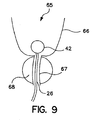
- FIG. 9 is a cutaway illustration of the positioning and anchoring of the distal portion of the optical fiber in the bladder, with the light diffuser portion of the optical fiber disposed in the prostatic portion of a patient's urethra.
- a patient portable PDT device 12 comprises a power source, or lithium ion rechargeable battery pack 14 ; a light source, or CCF tube 16 formed into an elongated “U” shape (best shown in FIG. 2 ) and adapted to draw power from the battery pack 14 ; at least one biocompatible optical fiber 18 (only one is shown) having a proximal portion 20 and a distal portion 22 , and adapted to channel light between the proximal portion 20 and the distal portion 22 ; and a coupling means 24 for coupling the CCF tube 16 in light channeling relation to the proximal portion 20 of the optical fiber 18 (best shown in FIG. 3 ).
- the optical fiber 18 is equipped with a diffusion means 26 (best shown in FIG. 1 ) for diffusing light as it exits the distal portion 22 of the optical fiber 18 .
- the battery pack 14 includes a warning light 28 and backup power reserve 30 .
- lithium ion rechargeable battery pack 14 one may use one or more nickel cadmium rechargeable batteries, one or more nickel metal hydride rechargeable batteries, or fuel cells, any other type of electrical power source polymer batteries, one or more, other rechargeable batteries or non-chargeable batteries that are sufficiently compact and substantially lightweight to be readily portable, i.e., readily carried about by the patient.
- a power source should preferably operate at a relatively low or ambient temperature.
- one or more laser diodes, fiber lasers, LEDs, incandescent lights, halogen lights, polymeric luminescent devices, other types of fluorescent lights, discharge lamps, or other electroluminescent devices can be employed for the light source, including those having at least one of the characteristics of being substantially compact, substantially lightweight, operating at a substantially low temperature, or being self-contained so that the light source is suitable for a portable system that is readily carried about by the patient.
- the diffusion means 26 any of the diffusers well known and documented in the prior art are suitable.
- the preferred coupling means 24 employed to channel light emitted by the light source in the proximal end of the optical fiber comprises a focusing lens 32 having a convex receiver side 34 and a convex delivery side 36 ; and a parabolic mirror 38 positioned so that the CCF tube 16 is generally disposed at or adjacent to the focal point of the parabolic mirror.
- the focusing lens 32 is positioned between the CCF tube 16 and the proximal portion 20 of the optical fiber 18 , so that the focusing lens receives the directly transmitted light from the CCF tube and the light reflected by the parabolic mirror 38 and focuses the light into the proximal end of the optical fiber 18 .
- the present invention further comprises an anchoring means 40 for anchoring the distal portion 22 of the optical fiber 18 within a patient's body.
- the anchoring means 40 preferably comprises a balloon 42 attached to the optical fiber 18 , a pressurized air source 44 that may be a syringe that is configured to deliver pressurized air (or other pressurized fluid) to the balloon 42 , a lumen 46 communicating between the air source 44 and the balloon 42 , and a selection means, or control 48 and valve 50 for selectively delivering pressurized air from the pressurized air source 44 to the balloon 42 and exhausting the pressurized air from the balloon 42 , so as to enable the selective inflation and deflation of the balloon.
- a pressurized air source 44 that may be a syringe that is configured to deliver pressurized air (or other pressurized fluid) to the balloon 42
- a lumen 46 communicating between the air source 44 and the balloon 42
- a selection means, or control 48 and valve 50 for selectively delivering pressurized air from
- the optical fiber 18 has a distal end 52 on which the balloon 42 is mounted.
- the lumen 46 extends in substantially parallel relationship to the optical fiber 18 and runs substantially the length of the optical fiber 18 , affixed to the side of the optical fiber over much of its length.
- the lumen is disposed within the optical fiber. Hollow optical fibers are well known in the optical fiber prior art.
- one or more balloons or other devices inflatable with pressurized fluids), lumens (or other channels capable of transporting gases or fluids), pressurized fluid sources, and/or other types of selection means (such as valves, switches, plugs or computer-, electrically- or mechanically-controlled components), can be employed in the present invention, in various configurations and combinations, without departing from the broad scope of the present invention.
- a heat activated shape memory metal anchor for example, one activated by heat developed by passing an electrical current therethrough, can be employed to hold the optical fiber in place.
- the battery pack 14 the battery pack 14 .
- COF tube 16 (best shown in FIG. 2 ) and coupling means 24 (best shown in FIG. 3 ) are mounted to means for enabling a patient to easily transport the battery pack 14 , CCF tube 16 , and coupling means 24 , i.e., at least one belt 54 (only one is shown) and are thus supported and substantially secured to a patient's body 56 as shown.
- the pressurized air source 44 (best shown in FIG.
- the air source preferably a syringe
- the air source preferably a syringe
- a needle 60 having a peel away sheath 62 is inserted into the patient's body while observed using an appropriate imaging system (such as CT, Ultrasound, MRI, X-ray) to the treatment site 58 within the patient's body 56 (not shown in full).
- an appropriate imaging system such as CT, Ultrasound, MRI, X-ray
- image guidance is preferred for achieving an accurate disposition of the optical fiber, it is optional and is not necessary, especially for disposition of the optical fiber to treat superficial lesions.
- the needle 60 is removed and the optical fiber 18 with the balloon 42 deflated is passed through the peel away sheath that was previously properly positioned at the treatment site.
- the position of the distal portion 22 is confirmed via the imaging modality used to pass the needle 60 , and the peel away sheath 62 is pulled up and split apart. The position of the distal portion 22 is then reconfirmed.
- the proximal portion of the optical fiber 18 is secured to the skin of the patient at an exit point 64 by way of suture, adhesive tape, or other fixation means (not shown).
- the pressurized air source 44 (best shown in FIG.
- pressurized air from the pressurized air source 44 is delivered to the balloon 42 in volume sufficient to inflate the balloon 42 so as to anchor the distal portion 22 of the optical fiber 18 at the treatment site 58 and tamponade any bleeding, which may have occurred during the introduction of the optical fiber 18 into the patient's body.
- the pressurized air source 44 is uncoupled from the lumen 46 .
- the pressurized air is prevented from escaping from the lumen 46 by the valve 50 (best seen in FIG. 4 ). Any dislodgement or displacement of the optical fiber 18 or its distal portion 22 due to movement of the patient will be resisted by the inflated balloon 42 .
- the patient fastens the belt 54 (best shown in FIG. 5 ), which supports and secures the battery pack 14 , CCF tube 16 (best shown in FIG. 2 ), and coupling means 24 (best shown in FIG. 3 ) to the patient.
- the battery pack 14 , CCF tube 16 , and coupling means 24 collectively are sufficiently compact and lightweight to be easily transported by the patient, and movement about by the patient during extended treatments is thus greatly facilitated.
- the CCF tube 16 is coupled to the battery pack 14 so as to draw electrical power.
- the proximal portion 20 of the optical fiber 18 is coupled to the CCF tube 16 by the coupling means 24 (best shown in FIG. 3 ).
- Other coupling means are possible as well, such as those described in U.S. Pat. No.
- the CCF tube 16 is activated with electrical current from the battery pack. As best shown in FIG. 3 , a quantity of light from the CCF tube 16 is reflected by the parabolic mirror 38 onto the receiver side 34 of the focusing lens 32 . The focusing lens 32 focuses light from the parabolic reflector and from the CCF tube into the proximal portion 20 of the optical fiber 18 . The light is channeled through the optical fiber 18 to the distal portion 22 of the optical fiber 18 , where it exits the distal portion 22 and is diffused by the diffusion means 26 . This diffused light is thus delivered to the treatment site 58 in a uniform manner.
- the battery pack 14 preferably provides at least 2 to 3 hours of operating time, depending on the power consumption of the light source, before it must be recharged. Inasmuch as it is removable and modular, it can be immediately replaced with a fresh battery pack and later recharged without interruption of the therapy. Once the battery pack 14 ′ begins to lose power, the warning light 28 on the battery pack 14 alerts the patient that the battery pack 14 must be replaced soon.
- the backup power reserve 30 provides the CCF tube 16 with power while the patient replaces the battery pack 14 with a fresh battery pack (not shown).
- the CCF tube 16 can be deactivated, the optical fiber 18 can be uncoupled from the coupling means 24 , and the valve 50 can be opened to allow the pressurized air in the balloon 42 to escape, to deflate the balloon 42 .
- the suture or adhesive tape securing the proximal portion of the optical fiber 18 , to the patient's body 56 at the exit point 64 can be removed, and the optical fiber 18 can be withdrawn from the patient's body.
- alternate preferred embodiments may incorporate a different positioning of the balloon 42 , such as at an intermediate point along the length of the optical fiber 18 to enable the distal portion 22 of the optical fiber 18 to abut a treatment site 58 as shown, rather than to be inserted within the treatment site 58 .
- light is directed toward the treatment site by a microlens 59 attached to the distal end of the fiber optic.
- the lens 59 enables light to be focused onto the peripheral boundary of the treatment site and penetrate into its depths without actually having to insert the fiber optic into the treatment site.
- Administering light therapy to the surface of the treatment site is preferable when the site should not be punctured with a needle, such as in the care of a highly vascular lesion, which would bleed excessively if the needle passed through a blood vessel.
- another aspect of the present invention is directed to a method for delivering light to a treatment site, comprising the steps of employing the power source, or battery pack 14 to energize the light source, or CCF tube 16 ; coupling the CCF tube 16 in light channeling relation to the proximal portion 20 of the biocompatible optical fiber 18 ; positioning the distal portion 22 of the optical fiber at the treatment site 58 within a patient's body; and administering the light through the optical fiber 18 to the treatment site 58 .
- the CCF tube 16 can be coupled in light channeling relation to the proximal portion by the coupling means 24 described in detail above and shown in FIG. 3 .
- the distal portion 22 can be positioned at the treatment site 58 in the manner outlined in detail above and shown in FIGS. 6 and 6A , where a needle 60 having a peel away sheath 62 is passed under image guidance (such as CT, Ultrasound, X-ray) to the treatment site 58 .
- image guidance such as CT, Ultrasound, X-ray
- the optical fiber 18 with the balloon 42 deflated is inserted through the peel away sheath.
- the position of the distal portion 22 is confirmed via the imaging modality used to position the needle 60 , and the peel away sheath 62 is pulled up and split apart. The position of the distal portion 22 is then reconfirmed. It should be readily apparent to one skilled in the art, based on the instant disclosure, that alternative steps maybe used in addition to or in place of those described above, without departing from the broad scope of the present invention.
- FIG. 9 illustrates treatment of bladder wherein the balloon 42 is inflated on the inside of the bladder wall 66 to keep the diffusion means 26 properly inserted in the urethra 67 .
- the prostate gland 68 is also schematically represented.
- another aspect of the present invention is directed to a method for anchoring the distal portion 22 of the optical fiber 18 at the treatment site 58 .
- This method includes the steps of mounting the balloon 42 to the optical fiber 18 ; coupling the pressurized air source 44 , configured to deliver pressurized air, in selective fluid communication with the balloon 42 ; positioning the balloon 42 (deflated) with the distal portion 22 into the treatment site 58 ; and activating the pressurized air source 44 to inflate the balloon 42 after positioning of the distal portion 22 of the optical fiber at the treatment site 58 .
- the pressurized air source 44 can be selectively coupled in fluid communication to the balloon 42 by the lumen 46 described in detail above, and employing the control 48 and valve 50 to control the inflation and deflation of the balloon, as described.
- the balloon 42 may be positioned at the distal end 52 of the optical fiber 18 as shown in FIGS. 7 and 7A , or at any intermediate point along the length of the optical fiber 18 as shown in FIGS. 8 and 8A .
- one or more balloons or other devices inflatable by gases or fluids), lumens (or other channels capable of transporting gases or fluids), pressurized fluid sources (or other gas or fluid sources), and selection means (such as valves, switches, plugs, or computer-, mechanically- or electrically-controlled components, such as shape memory metal anchoring devices), in various configurations and combinations, without departing from the broad scope of the present invention.
- yet another aspect of the present invention pertains to a method for securing the battery pack 14 and the CCF tube 16 to a patient.
- This method comprises the steps of securing the battery pack 14 and the CCF tube 16 to the belt 56 and attaching the belt 56 to a patient, as shown in FIG. 5 .
Abstract
Description
Claims (16)
Priority Applications (1)
| Application Number | Priority Date | Filing Date | Title |
|---|---|---|---|
| US10/211,784 US6986782B2 (en) | 1999-01-15 | 2002-08-01 | Ambulatory photodynamic therapy |
Applications Claiming Priority (2)
| Application Number | Priority Date | Filing Date | Title |
|---|---|---|---|
| US09/232,129 US6454789B1 (en) | 1999-01-15 | 1999-01-15 | Patient portable device for photodynamic therapy |
| US10/211,784 US6986782B2 (en) | 1999-01-15 | 2002-08-01 | Ambulatory photodynamic therapy |
Related Parent Applications (1)
| Application Number | Title | Priority Date | Filing Date |
|---|---|---|---|
| US09/232,129 Division US6454789B1 (en) | 1999-01-15 | 1999-01-15 | Patient portable device for photodynamic therapy |
Publications (2)
| Publication Number | Publication Date |
|---|---|
| US20020198576A1 US20020198576A1 (en) | 2002-12-26 |
| US6986782B2 true US6986782B2 (en) | 2006-01-17 |
Family
ID=22871981
Family Applications (2)
| Application Number | Title | Priority Date | Filing Date |
|---|---|---|---|
| US09/232,129 Expired - Lifetime US6454789B1 (en) | 1999-01-15 | 1999-01-15 | Patient portable device for photodynamic therapy |
| US10/211,784 Expired - Lifetime US6986782B2 (en) | 1999-01-15 | 2002-08-01 | Ambulatory photodynamic therapy |
Family Applications Before (1)
| Application Number | Title | Priority Date | Filing Date |
|---|---|---|---|
| US09/232,129 Expired - Lifetime US6454789B1 (en) | 1999-01-15 | 1999-01-15 | Patient portable device for photodynamic therapy |
Country Status (9)
| Country | Link |
|---|---|
| US (2) | US6454789B1 (en) |
| EP (1) | EP1144049B1 (en) |
| JP (1) | JP4358447B2 (en) |
| AT (1) | ATE390172T1 (en) |
| AU (1) | AU2725200A (en) |
| CA (1) | CA2356478C (en) |
| DE (1) | DE60038436T2 (en) |
| ES (1) | ES2302687T3 (en) |
| WO (1) | WO2000041768A1 (en) |
Cited By (49)
| Publication number | Priority date | Publication date | Assignee | Title |
|---|---|---|---|---|
| US20060167531A1 (en) * | 2005-01-25 | 2006-07-27 | Michael Gertner | Optical therapies and devices |
| US20060200212A1 (en) * | 2005-02-17 | 2006-09-07 | Brawn Peter R | Light therapy device for treatment of bone disorders and biostimulation of bone and soft tissue |
| US20060206173A1 (en) * | 2005-03-14 | 2006-09-14 | Michael Gertner | Devices, Methods and Kits for Radiation Treatment via a Target Body Surface |
| US20070021923A1 (en) * | 2005-07-21 | 2007-01-25 | Searete Llc, A Limited Liability Corporation Of The State Of Delaware | Selective resonance of chemical structures |
| US20070021458A1 (en) * | 2005-07-21 | 2007-01-25 | Searete Llc, A Limited Liability Corporation Of The State Of Delaware | Selective resonance of bodily agents |
| US20070021924A1 (en) * | 2005-07-21 | 2007-01-25 | Ishikawa Muriel Y | Selective resonance of chemical structures |
| US20070208395A1 (en) * | 2005-10-05 | 2007-09-06 | Leclerc Norbert H | Phototherapy Device and Method of Providing Phototherapy to a Body Surface |
| US20070219600A1 (en) * | 2006-03-17 | 2007-09-20 | Michael Gertner | Devices and methods for targeted nasal phototherapy |
| WO2007119084A1 (en) | 2006-04-19 | 2007-10-25 | Ruder Boskovic Institute | Intelligent sequential illuminating device for photodynamic therapy |
| US20070248930A1 (en) * | 2005-02-17 | 2007-10-25 | Biolux Research Ltd. | Light therapy apparatus and methods |
| US20080033519A1 (en) * | 2003-03-14 | 2008-02-07 | Light Sciences Oncology, Inc. | Light generating device for intravascular use |
| US20080069738A1 (en) * | 2005-07-21 | 2008-03-20 | Searete Llc, A Limited Liability Corporation Of The State Of Delaware | Selective resonant reconfiguration of chemical structures |
| US20080273329A1 (en) * | 2004-06-15 | 2008-11-06 | Belek Ronald E | High Power Led Electro-Optic Assembly |
| US20090057697A1 (en) * | 2004-10-28 | 2009-03-05 | Henkel Corporation | Led assembly with led-reflector interconnect |
| US20090071817A1 (en) * | 2005-07-21 | 2009-03-19 | Searete Llc | Selective resonance of chemical structures |
| US20090142415A1 (en) * | 2005-07-21 | 2009-06-04 | Searete Llc | Selective resonance of chemical structures |
| US20100118139A1 (en) * | 2008-07-19 | 2010-05-13 | Yuming Huang | Portable Device to Detect the Spin of Table Tennis Ball |
| US20100210995A1 (en) * | 2006-05-02 | 2010-08-19 | Cook Incorporated | Systems and methods for treating superficial venous malformations like spider veins |
| US7820143B2 (en) | 2002-06-27 | 2010-10-26 | Health Research, Inc. | Water soluble tetrapyrollic photosensitizers for photodynamic therapy |
| US20100274330A1 (en) * | 2003-03-14 | 2010-10-28 | Light Sciences Oncology, Inc. | Device for treatment of blood vessels using light |
| US7897140B2 (en) | 1999-12-23 | 2011-03-01 | Health Research, Inc. | Multi DTPA conjugated tetrapyrollic compounds for phototherapeutic contrast agents |
| US7989839B2 (en) | 2002-08-23 | 2011-08-02 | Koninklijke Philips Electronics, N.V. | Method and apparatus for using light emitting diodes |
| US8047686B2 (en) | 2006-09-01 | 2011-11-01 | Dahm Jonathan S | Multiple light-emitting element heat pipe assembly |
| US8096691B2 (en) | 1997-09-25 | 2012-01-17 | Koninklijke Philips Electronics N V | Optical irradiation device |
| US8113830B2 (en) | 2005-05-27 | 2012-02-14 | Kerr Corporation | Curing light instrument |
| US8231383B2 (en) | 2002-08-08 | 2012-07-31 | Kerr Corporation | Curing light instrument |
| US20120259187A1 (en) * | 2011-01-24 | 2012-10-11 | Ceramoptec Industries, Inc. | Dynamic colorectal pdt application |
| US8346484B2 (en) | 2005-07-21 | 2013-01-01 | The Invention Science Fund I, Llc | Selective resonance of chemical structures |
| US8535360B2 (en) | 2006-05-02 | 2013-09-17 | Green Medical, Ltd. | Systems and methods for treating superficial venous malformations like spider veins |
| US8568140B2 (en) | 1998-01-20 | 2013-10-29 | Jozef Kovac | Apparatus and method for curing materials with radiation |
| US9066777B2 (en) | 2009-04-02 | 2015-06-30 | Kerr Corporation | Curing light device |
| US9072572B2 (en) | 2009-04-02 | 2015-07-07 | Kerr Corporation | Dental light device |
| US9211332B2 (en) | 2005-07-21 | 2015-12-15 | The Invention Science Fund I, Llc | Selective resonance of bodily agents |
| US9242118B2 (en) | 2010-12-08 | 2016-01-26 | Biolux Research Ltd. | Methods useful for remodeling maxillofacial bone using light therapy and a functional appliance |
| US9370449B2 (en) | 2014-02-26 | 2016-06-21 | Luma Therapeutics, Inc. | Phototherapy dressing for treating psoriasis |
| US9427465B2 (en) | 2005-07-21 | 2016-08-30 | Deep Science, Llc | Selective resonance of chemical structures |
| US9717927B2 (en) | 2013-02-07 | 2017-08-01 | Rocomp Global, L.L.C. | Electromagnetic radiation targeting devices, assemblies, systems and methods |
| US9726435B2 (en) | 2002-07-25 | 2017-08-08 | Jonathan S. Dahm | Method and apparatus for using light emitting diodes for curing |
| US9730780B2 (en) | 2013-10-22 | 2017-08-15 | Biolux Research Ltd. | Intra-oral light-therapy apparatuses and methods for their use |
| WO2018022775A1 (en) | 2016-07-27 | 2018-02-01 | Zhang Jack K | Componentry and devices for light therapy delivery and methods related thereto |
| US9968800B2 (en) | 2016-02-09 | 2018-05-15 | Luma Therapeutics, Inc. | Methods, compositions and apparatuses for treating psoriasis by phototherapy |
| US10307610B2 (en) | 2006-01-18 | 2019-06-04 | Light Sciences Oncology Inc. | Method and apparatus for light-activated drug therapy |
| US10737110B2 (en) | 2011-11-09 | 2020-08-11 | John Stephan | Light therapy apparatus |
| US10744341B2 (en) | 2017-08-02 | 2020-08-18 | Multi Radiance Medical | System and method for directing light into a patients eye |
| USD906559S1 (en) | 2018-04-26 | 2020-12-29 | Milwaukee Electric Tool Corporation | Light |
| US11098858B2 (en) | 2018-04-26 | 2021-08-24 | Milwaukee Electric Tool Corporation | Portable light having a pivotable light head |
| US11458329B2 (en) | 2016-07-27 | 2022-10-04 | Z2020, Llc | Componentry and devices for light therapy delivery and methods related thereto |
| US11638833B2 (en) | 2017-08-02 | 2023-05-02 | Multi Radiance Medical | Reducing light polution in photobiomodulation therapy of a patients eye |
| USRE49724E1 (en) * | 2008-09-29 | 2023-11-14 | Tom Kerber | Device for photodynamical therapy of cancer |
Families Citing this family (50)
| Publication number | Priority date | Publication date | Assignee | Title |
|---|---|---|---|---|
| US6602274B1 (en) | 1999-01-15 | 2003-08-05 | Light Sciences Corporation | Targeted transcutaneous cancer therapy |
| EP1131099A2 (en) | 1999-01-15 | 2001-09-12 | Light Sciences Corporation | Noninvasive vascular therapy |
| US6454789B1 (en) | 1999-01-15 | 2002-09-24 | Light Science Corporation | Patient portable device for photodynamic therapy |
| US20050073839A1 (en) * | 2003-09-18 | 2005-04-07 | The Litebook Company Ltd | Light therapy device |
| CA2317319A1 (en) | 2000-03-14 | 2001-09-14 | The Litebook Company Ltd | Light therapy device |
| SE0003673D0 (en) * | 2000-10-10 | 2000-10-10 | Medeikonos Ab | Radiation device for photodynamic therapy |
| US20020087206A1 (en) * | 2000-12-28 | 2002-07-04 | Henry Hirschberg | Implantable intracranial photo applicator for long term fractionated photodynamic and radiation therapy in the brain and method of using the same |
| US7101384B2 (en) * | 2001-03-08 | 2006-09-05 | Tru-Light Corporation | Light processing of selected body components |
| US20050004632A1 (en) * | 2001-03-08 | 2005-01-06 | Mellen-Thomas Benedict | Universal light processing for a human body |
| US7316769B2 (en) * | 2001-03-19 | 2008-01-08 | Cornell Research Foundation, Inc. | Length-dependent recoil separation of long molecules |
| US7303578B2 (en) | 2001-11-01 | 2007-12-04 | Photothera, Inc. | Device and method for providing phototherapy to the brain |
| US20030130624A1 (en) * | 2002-01-07 | 2003-07-10 | Kowalik Francis C. | Medical infusion system with integrated power supply and pump therefor |
| US20040093056A1 (en) | 2002-10-26 | 2004-05-13 | Johnson Lianw M. | Medical appliance delivery apparatus and method of use |
| US20040101822A1 (en) * | 2002-11-26 | 2004-05-27 | Ulrich Wiesner | Fluorescent silica-based nanoparticles |
| US7637934B2 (en) * | 2003-03-31 | 2009-12-29 | Merit Medical Systems, Inc. | Medical appliance optical delivery and deployment apparatus and method |
| US7604660B2 (en) | 2003-05-01 | 2009-10-20 | Merit Medical Systems, Inc. | Bifurcated medical appliance delivery apparatus and method |
| US10252079B2 (en) * | 2003-06-06 | 2019-04-09 | Koninklijke Philips N.V. | Hand-held light therapy apparatus |
| US6974224B2 (en) * | 2003-07-30 | 2005-12-13 | Tru-Light Corporation | Modularized light processing of body components |
| US20060095102A1 (en) * | 2003-09-17 | 2006-05-04 | Thomas Perez | Method and apparatus for sublingual application of light to blood |
| US7052167B2 (en) * | 2004-02-25 | 2006-05-30 | Vanderschuit Carl R | Therapeutic devices and methods for applying therapy |
| US8257416B2 (en) * | 2004-02-25 | 2012-09-04 | Vanderschuit Carl R | Therapeutic devices and methods for applying therapy |
| US7862594B2 (en) * | 2004-02-27 | 2011-01-04 | Custom Spine, Inc. | Polyaxial pedicle screw assembly |
| US20060004281A1 (en) * | 2004-06-30 | 2006-01-05 | Michael Saracen | Vest-based respiration monitoring system |
| US20060095100A1 (en) * | 2004-10-29 | 2006-05-04 | Kian Shin Lee | Method and apparatus for regulating light administered at a patient treatment site |
| US20060173514A1 (en) * | 2005-02-02 | 2006-08-03 | Advanced Photodynamic Technologies, Inc. | Wound treatment device for photodynamic therapy and method of using same |
| US20060229689A1 (en) * | 2005-04-08 | 2006-10-12 | Led Technologies, Llc | LED therapy device |
| US8084001B2 (en) * | 2005-05-02 | 2011-12-27 | Cornell Research Foundation, Inc. | Photoluminescent silica-based sensors and methods of use |
| US8057464B2 (en) | 2006-05-03 | 2011-11-15 | Light Sciences Oncology, Inc. | Light transmission system for photoreactive therapy |
| US8480662B2 (en) * | 2007-08-22 | 2013-07-09 | Cardiac Pacemakers, Inc. | Systems and devices for photoablation |
| US20090088822A1 (en) * | 2007-09-27 | 2009-04-02 | Led Healing Light, Llc | Therapeutic pulse laser methods and apparatus |
| CA2891990C (en) | 2008-05-20 | 2022-07-26 | Ralph Sebastian Dacosta | Device and method for fluorescence-based imaging and monitoring |
| US7993640B2 (en) | 2008-08-06 | 2011-08-09 | Light Sciences Oncology, Inc. | Enhancement of light activated therapy by immune augmentation using anti-CTLA-4 antibody |
| EP2229979A1 (en) | 2009-03-18 | 2010-09-22 | Norbert Hilty | Irradiation-cooling combination for use in photodynamic therapy |
| US20110008372A1 (en) * | 2009-07-08 | 2011-01-13 | Light Sciences Oncology, Inc. | Enhancement of light activated drug therapy through combination with other therapeutic agents |
| CN103003368B (en) | 2010-03-17 | 2016-09-21 | 纳诺洛吉卡股份公司 | Folic acid fluorescent material, the multi-fluorescence porous combination thing of material and the potential application thereof strengthened |
| JP5970475B2 (en) * | 2011-01-27 | 2016-08-17 | 日東電工株式会社 | Phototherapy device and method containing optionally substituted terphenyl and quaterphenyl compounds |
| US10195379B2 (en) * | 2012-03-06 | 2019-02-05 | Koninklijke Philips N.V. | Patient interface having illuminated portion |
| CN102715981B (en) * | 2012-06-29 | 2014-08-20 | 深圳普门科技有限公司 | Annular light spot obtaining device for light therapy equipment, glaucoma treatment device and method for controlling annular light spots in annular light spot obtaining device |
| US9949889B2 (en) | 2013-11-11 | 2018-04-24 | Joylux, Inc. | At-home light-emitting diode and massage device for vaginal rejuvenation |
| DK3171765T3 (en) | 2014-07-24 | 2021-11-01 | Univ Health Network | COLLECTION AND ANALYSIS OF DATA FOR DIAGNOSTIC PURPOSES |
| WO2016035082A1 (en) * | 2014-09-04 | 2016-03-10 | Dr. Eyal Bressler Ltd. | Assembly for photodynamic therapy |
| US10179085B2 (en) | 2015-10-02 | 2019-01-15 | Joylux, Inc. | Light-emitting diode and massage device for delivering focused light for vaginal rejuvenation |
| KR20170128934A (en) * | 2016-05-16 | 2017-11-24 | 한국과학기술연구원 | Optical Control System for Lower Urinary Tract Dysfunctions |
| US11251635B2 (en) | 2017-12-19 | 2022-02-15 | Welch Allyn, Inc. | Vital signs monitor with a removable and dischargable battery |
| US11529153B2 (en) | 2020-08-21 | 2022-12-20 | University Of Washington | Vaccine generation |
| WO2022040258A1 (en) | 2020-08-21 | 2022-02-24 | University Of Washington | Disinfection method and apparatus |
| US11425905B2 (en) | 2020-09-02 | 2022-08-30 | University Of Washington | Antimicrobial preventive netting |
| WO2022103775A1 (en) | 2020-11-12 | 2022-05-19 | Singletto Inc. | Microbial disinfection for personal protection equipment |
| USD959683S1 (en) | 2021-04-30 | 2022-08-02 | Shenzhen Yihong Lighting Co., Ltd. | Red light therapy belt |
| US11878183B1 (en) | 2021-06-14 | 2024-01-23 | Jaals, Llc | Laser therapy device and method of conducting laser therapy |
Citations (100)
| Publication number | Priority date | Publication date | Assignee | Title |
|---|---|---|---|---|
| US2797213A (en) | 1954-08-20 | 1957-06-25 | Gen Aniline & Film Corp | Rosin derivatives of diazonaphthol-and diazophenol-sulfonamides |
| US3046120A (en) | 1950-10-31 | 1962-07-24 | Azoplate Corp | Light-sensitive layers for photomechanical reproduction |
| US3046118A (en) | 1949-07-23 | 1962-07-24 | Azoplate Corp | Process of making printing plates and light sensitive material suitable for use therein |
| US4337759A (en) | 1979-10-10 | 1982-07-06 | John M. Popovich | Radiant energy concentration by optical total internal reflection |
| US4675338A (en) | 1984-07-18 | 1987-06-23 | Nippon Petrochemicals Co., Ltd. | Tetrapyrrole therapeutic agents |
| US4693556A (en) | 1985-06-04 | 1987-09-15 | Laser Therapeutics, Inc. | Apparatus for producing a spherical pattern of light and method of manufacture |
| US4693885A (en) | 1984-07-18 | 1987-09-15 | Nippon Petrochemicals Co., Ltd. | Tetrapyrrole therapeutic agents |
| US4746840A (en) * | 1987-04-06 | 1988-05-24 | Lim Kenneth S | Fluorescent reflector lamp assembly |
| US4753958A (en) | 1985-02-07 | 1988-06-28 | University Of Cal | Photochemotherapy of epithelial diseases with derivatives of hematoporphyrins |
| US4823244A (en) | 1988-01-29 | 1989-04-18 | Niagara Medical Innovations Inc. | Light source assembly |
| US4849207A (en) | 1985-10-23 | 1989-07-18 | Nihon Medi-Physics Co., Ltd. | Porphyrin derivatives |
| US4932934A (en) | 1982-09-27 | 1990-06-12 | Health Research, Inc. | Methods for treatment of tumors |
| US4998930A (en) | 1988-08-03 | 1991-03-12 | Phototherapeutic Systems | Intracavity laser phototherapy method |
| US5002962A (en) | 1988-07-20 | 1991-03-26 | Health Research, Inc. | Photosensitizing agents |
| US5026367A (en) | 1988-03-18 | 1991-06-25 | Cardiovascular Laser Systems, Inc. | Laser angioplasty catheter and a method for use thereof |
| US5055446A (en) | 1988-10-21 | 1991-10-08 | University Of Cincinnati | Method to improve survival of patients during sepsis by diet composition |
| US5169395A (en) * | 1991-04-26 | 1992-12-08 | Pdt Cardiovascular, Inc. | Laser delivery system |
| US5171749A (en) | 1987-01-20 | 1992-12-15 | University Of British Columbia | Wavelength-specific cytotoxic agents |
| US5190536A (en) | 1988-11-08 | 1993-03-02 | Health Research, Inc. | Submersible lens fiberoptic assembly for use in PDT treatment |
| US5209748A (en) * | 1989-08-24 | 1993-05-11 | S.L.T. Japan Co., Ltd. | Laser light irradiation apparatus |
| US5263925A (en) | 1991-07-22 | 1993-11-23 | Gilmore Jr Thomas F | Photopheresis blood treatment |
| US5283255A (en) | 1987-01-20 | 1994-02-01 | The University Of British Columbia | Wavelength-specific cytotoxic agents |
| US5320618A (en) * | 1990-04-09 | 1994-06-14 | Morgan Gustafsson | Device for treatment of undesired skin disfigurements |
| US5344434A (en) | 1991-12-29 | 1994-09-06 | Technion Research & Development Foundation, Ltd. | Apparatus for the photodynamic therapy treatment |
| US5404869A (en) | 1992-04-16 | 1995-04-11 | Tir Technologies, Inc. | Faceted totally internally reflecting lens with individually curved faces on facets |
| US5445608A (en) | 1993-08-16 | 1995-08-29 | James C. Chen | Method and apparatus for providing light-activated therapy |
| US5454794A (en) * | 1993-10-15 | 1995-10-03 | Pdt Systems, Inc. | Steerable light diffusing catheter |
| US5456661A (en) | 1994-03-31 | 1995-10-10 | Pdt Cardiovascular | Catheter with thermally stable balloon |
| US5474765A (en) | 1992-03-23 | 1995-12-12 | Ut Sw Medical Ctr At Dallas | Preparation and use of steroid-polyanionic polymer-based conjugates targeted to vascular endothelial cells |
| US5474528A (en) | 1994-03-21 | 1995-12-12 | Dusa Pharmaceuticals, Inc. | Combination controller and patch for the photodynamic therapy of dermal lesion |
| US5482698A (en) | 1993-04-22 | 1996-01-09 | Immunomedics, Inc. | Detection and therapy of lesions with biotin/avidin polymer conjugates |
| US5484778A (en) | 1990-07-17 | 1996-01-16 | University Hospitals Of Cleveland | Phthalocyanine photosensitizers for photodynamic therapy and methods for their use |
| US5484803A (en) | 1992-09-21 | 1996-01-16 | Quadra Logic Technologies Inc. | Transcutaneous in vivo activation of photosensitive agents in blood |
| US5491765A (en) * | 1992-12-08 | 1996-02-13 | Olympus Optical Co., Ltd. | Light source devices for endoscopes |
| US5494793A (en) | 1986-12-15 | 1996-02-27 | British Technology Group Usa Inc. | Monomeric phthalocyanine reagents |
| US5514669A (en) | 1993-09-29 | 1996-05-07 | Medical College Of Ohio | Use of photodynamic therapy to treat prostatic tissue |
| US5519534A (en) | 1994-05-25 | 1996-05-21 | The Government Of The United States Of America As Represented By The Secretary Of The Department Of Health And Human Services | Irradiance attachment for an optical fiber to provide a uniform level of illumination across a plane |
| US5543514A (en) | 1989-12-21 | 1996-08-06 | Board Of Regents, The University Of Texas System | Water-soluble sapphyrins |
| US5565552A (en) | 1992-01-21 | 1996-10-15 | Pharmacyclics, Inc. | Method of expanded porphyrin-oligonucleotide conjugate synthesis |
| US5571152A (en) | 1995-05-26 | 1996-11-05 | Light Sciences Limited Partnership | Microminiature illuminator for administering photodynamic therapy |
| US5576013A (en) | 1995-03-21 | 1996-11-19 | Eastern Virginia Medical School | Treating vascular and neoplastic tissues |
| US5591855A (en) | 1994-10-14 | 1997-01-07 | Cephalon, Inc. | Fused pyrrolocarbazoles |
| US5594136A (en) | 1989-12-21 | 1997-01-14 | Pharmacyclics, Inc. | Texaphyrin solid supports and devices |
| US5613769A (en) | 1992-04-16 | 1997-03-25 | Tir Technologies, Inc. | Tir lens apparatus having non-circular configuration about an optical axis |
| US5616140A (en) | 1994-03-21 | 1997-04-01 | Prescott; Marvin | Method and apparatus for therapeutic laser treatment |
| US5630996A (en) | 1992-06-09 | 1997-05-20 | Neorx Corporation | Two-step pretargeting methods using improved biotin-active agent conjugates |
| US5634711A (en) | 1993-09-13 | 1997-06-03 | Kennedy; John | Portable light emitting apparatus with a semiconductor emitter array |
| US5643334A (en) | 1995-02-07 | 1997-07-01 | Esc Medical Systems Ltd. | Method and apparatus for the diagnostic and composite pulsed heating and photodynamic therapy treatment |
| US5645562A (en) | 1995-03-13 | 1997-07-08 | Cordis Corporation | Balloon catheter with light conductor |
| US5655832A (en) | 1992-04-16 | 1997-08-12 | Tir Technologies, Inc. | Multiple wavelength light processor |
| US5676453A (en) | 1992-04-16 | 1997-10-14 | Tir Technologies, Inc. | Collimating TIR lens devices employing fluorescent light sources |
| US5686113A (en) | 1995-03-21 | 1997-11-11 | Temple University Of The Commonwealth System Of Higher Education | Microcapsules of predetermined peptide(s) specificity (ies), their preparation and uses |
| US5698866A (en) | 1994-09-19 | 1997-12-16 | Pdt Systems, Inc. | Uniform illuminator for phototherapy |
| US5700243A (en) | 1992-10-30 | 1997-12-23 | Pdt Systems, Inc. | Balloon perfusion catheter |
| US5702432A (en) | 1996-10-03 | 1997-12-30 | Light Sciences Limited Partnership | Intracorporeal light treatment of blood |
| US5703896A (en) | 1995-06-07 | 1997-12-30 | The Regents Of The University Of Colorado | Silicon quantum dot laser |
| US5705518A (en) | 1992-11-20 | 1998-01-06 | University Of British Columbia | Method of activating photosensitive agents |
| US5707401A (en) | 1994-03-10 | 1998-01-13 | Esc Medical Systems, Ltd. | Apparatus for an efficient photodynamic treatment |
| US5709653A (en) | 1996-07-25 | 1998-01-20 | Cordis Corporation | Photodynamic therapy balloon catheter with microporous membrane |
| US5715837A (en) | 1996-08-29 | 1998-02-10 | Light Sciences Limited Partnership | Transcutaneous electromagnetic energy transfer |
| US5735817A (en) | 1995-05-19 | 1998-04-07 | Shantha; T. R. | Apparatus for transsphenoidal stimulation of the pituitary gland and adjoining brain structures |
| US5741316A (en) | 1996-12-02 | 1998-04-21 | Light Sciences Limited Partnership | Electromagnetic coil configurations for power transmission through tissue |
| US5746495A (en) | 1997-02-05 | 1998-05-05 | Klamm; Thomas L. | Portable work light with optical fiber adapter |
| US5746494A (en) | 1994-11-22 | 1998-05-05 | Asahi Kogaku Kogyo Kabushiki Kaisha | Illuminating apparatus of endoscope |
| US5757557A (en) | 1997-06-09 | 1998-05-26 | Tir Technologies, Inc. | Beam-forming lens with internal cavity that prevents front losses |
| US5766222A (en) | 1997-07-07 | 1998-06-16 | Petit; Michael G. | Nipple illuminator for photodynamic therapy |
| US5766234A (en) | 1996-03-07 | 1998-06-16 | Light Sciences Limited Partnership | Implanting and fixing a flexible probe for administering a medical therapy at a treatment site within a patient'body |
| US5770730A (en) | 1996-03-08 | 1998-06-23 | Health Research, Inc. | Synthesis of carbodimide analogs of chlorins and bacteriochlorins and their use for diagnosis and treatment of cancer |
| US5769844A (en) | 1991-06-26 | 1998-06-23 | Ghaffari; Shahriar | Conventional light-pumped high power system for medical applications |
| US5776427A (en) | 1992-03-05 | 1998-07-07 | Board Of Regents, The University Of Texas System | Methods for targeting the vasculature of solid tumors |
| US5775339A (en) | 1996-03-26 | 1998-07-07 | Pharmacyclics, Inc. | Photodynamic therapy of pigment-related lesions |
| US5776175A (en) | 1995-09-29 | 1998-07-07 | Esc Medical Systems Ltd. | Method and apparatus for treatment of cancer using pulsed electromagnetic radiation |
| US5782896A (en) | 1997-01-29 | 1998-07-21 | Light Sciences Limited Partnership | Use of a shape memory alloy to modify the disposition of a device within an implantable medical probe |
| US5797868A (en) | 1996-07-25 | 1998-08-25 | Cordis Corporation | Photodynamic therapy balloon catheter |
| US5798349A (en) | 1994-03-14 | 1998-08-25 | The General Hospital Corporation | Use of green porphyrins to treat neovasculature in the eye |
| US5803575A (en) | 1995-03-22 | 1998-09-08 | U.S. Philips Corporation | Light generator for introducing light into optical fibers |
| US5807881A (en) | 1992-05-27 | 1998-09-15 | Quadra Logic Technologies, Inc. | Method for selectively reducing activated leukocyte cell population |
| US5806955A (en) | 1992-04-16 | 1998-09-15 | Tir Technologies, Inc. | TIR lens for waveguide injection |
| US5811248A (en) | 1986-03-31 | 1998-09-22 | Charter Ventures | Atherosclerotic plaque specific antigens, antibodies thereto, and uses thereof |
| US5814008A (en) | 1996-07-29 | 1998-09-29 | Light Sciences Limited Partnership | Method and device for applying hyperthermia to enhance drug perfusion and efficacy of subsequent light therapy |
| US5817048A (en) | 1997-03-20 | 1998-10-06 | Brown University Research Foundation | Ultrasonic alternative to laser-based photodynamic therapy |
| US5824657A (en) | 1997-03-18 | 1998-10-20 | Cubist Pharmaceuticals, Inc. | Aminoacyl sulfamides for the treatment of hyperproliferative disorders |
| US5827186A (en) | 1997-04-11 | 1998-10-27 | Light Sciences Limited Partnership | Method and PDT probe for minimizing CT and MRI image artifacts |
| US5829448A (en) | 1996-10-30 | 1998-11-03 | Photogen, Inc. | Method for improved selectivity in photo-activation of molecular agents |
| US5835648A (en) | 1996-03-07 | 1998-11-10 | Miravant Systems, Inc. | Surface illuminator for photodynamic therapy |
| US5843143A (en) | 1992-10-23 | 1998-12-01 | Cancer Research Campaign Technology Ltd. | Light source |
| US5849027A (en) | 1996-09-04 | 1998-12-15 | Mbg Technologies, Inc. | Photodynamic therapy method and apparatus |
| US5851225A (en) | 1994-03-18 | 1998-12-22 | Spectra Science Corporation | Photoemitting catheters and other structures suitable for use in photo-dynamic therapy and other applications |
| US5855866A (en) | 1992-03-05 | 1999-01-05 | Board Of Regenis, The University Of Texas System | Methods for treating the vasculature of solid tumors |
| US5863538A (en) | 1992-03-05 | 1999-01-26 | Board Of Regents, The University Of Texas System | Compositions for targeting the vasculature of solid tumors |
| US5865840A (en) | 1997-10-22 | 1999-02-02 | Light Sciences Limited Partnership | Enhancement of light activation effect by immune augmentation |
| US5876427A (en) | 1997-01-29 | 1999-03-02 | Light Sciences Limited Partnership | Compact flexible circuit configuration |
| US5881200A (en) | 1994-09-29 | 1999-03-09 | British Telecommunications Public Limited Company | Optical fibre with quantum dots |
| US5882328A (en) | 1995-01-13 | 1999-03-16 | Qlt Phototherapeutics, Inc. | Method to prevent transplant rejection |
| US5882779A (en) | 1994-11-08 | 1999-03-16 | Spectra Science Corporation | Semiconductor nanocrystal display materials and display apparatus employing same |
| US5906579A (en) | 1996-08-16 | 1999-05-25 | Smith & Nephew Endoscopy, Inc. | Through-wall catheter steering and positioning |
| US5909670A (en) | 1995-01-09 | 1999-06-01 | U S West, Inc. | Method and system for playback of advertisements in an electronic classified advertising system |
| US5912257A (en) | 1995-09-06 | 1999-06-15 | The Research Foundation Of State University Of New York | Two-photon upconverting dyes and applications |
| US6048359A (en) * | 1997-08-25 | 2000-04-11 | Advanced Photodynamic Technologies, Inc. | Spatial orientation and light sources and method of using same for medical diagnosis and photodynamic therapy |
| US6429936B1 (en) * | 1998-11-06 | 2002-08-06 | C&L Instruments | Synchronous multiwavelength fluorescence system |
Family Cites Families (43)
| Publication number | Priority date | Publication date | Assignee | Title |
|---|---|---|---|---|
| JPS5384998A (en) | 1976-12-29 | 1978-07-26 | Takashi Yamamoto | Cancer controlling method |
| JPS57185220A (en) | 1981-05-07 | 1982-11-15 | Yakult Honsha Co Ltd | Carcinostatic agent containing chlorophyll derivative as active component |
| US5919217A (en) * | 1987-12-08 | 1999-07-06 | Medic-Light, Inc. | Portable phototherapy unit |
| US5913834A (en) * | 1993-11-04 | 1999-06-22 | Francais; Caramia | System for imparting sensory effects across a mother's abdomen to a fetus and monitoring effects on the fetus |
| US5989245A (en) * | 1994-03-21 | 1999-11-23 | Prescott; Marvin A. | Method and apparatus for therapeutic laser treatment |
| US5685308A (en) | 1994-08-05 | 1997-11-11 | Acuson Corporation | Method and apparatus for receive beamformer system |
| JPH0947518A (en) * | 1995-06-26 | 1997-02-18 | Lederle Japan Ltd | Optical fiber laser probe for photodynamic therapy |
| DE29517716U1 (en) * | 1995-11-08 | 1996-01-25 | Waldmann Gmbh & Co Herbert | Device for photodynamic radiation |
| US5952329A (en) * | 1996-01-23 | 1999-09-14 | The General Hospital Corporation | Benzophenothiazine and benzoporphyrin dye combination photodynamic therapy of tumors |
| US6135620A (en) * | 1996-04-10 | 2000-10-24 | Re-Energy, Inc. | CCFL illuminated device |
| WO1998006456A1 (en) | 1996-08-08 | 1998-02-19 | Light Sciences Limited Partnership | Method and apparatus to treat gingival and periodontal disease |
| US6080160A (en) | 1996-12-04 | 2000-06-27 | Light Sciences Limited Partnership | Use of shape memory alloy for internally fixing light emitting device at treatment site |
| US6021347A (en) * | 1996-12-05 | 2000-02-01 | Herbst; Ewa | Electrochemical treatment of malignant tumors |
| US5997569A (en) | 1997-01-29 | 1999-12-07 | Light Sciences Limited Partnership | Flexible and adjustable grid for medical therapy |
| US5957960A (en) | 1997-05-05 | 1999-09-28 | Light Sciences Limited Partnership | Internal two photon excitation device for delivery of PDT to diffuse abnormal cells |
| JP2002508753A (en) | 1997-05-20 | 2002-03-19 | エール ユニバーシティ | Drug dependent treatment using opiate antagonists and serotonin compounds |
| US6100893A (en) * | 1997-05-23 | 2000-08-08 | Light Sciences Limited Partnership | Constructing solid models using implicit functions defining connectivity relationships among layers of an object to be modeled |
| US5921244A (en) | 1997-06-11 | 1999-07-13 | Light Sciences Limited Partnership | Internal magnetic device to enhance drug therapy |
| SE9702272L (en) | 1997-06-13 | 1998-12-14 | Ericsson Telefon Ab L M | Device in a radio unit |
| US6138681A (en) | 1997-10-13 | 2000-10-31 | Light Sciences Limited Partnership | Alignment of external medical device relative to implanted medical device |
| US6071944A (en) * | 1997-11-12 | 2000-06-06 | Bowling Green State University | Method of treatment of pigmented cancer cells utilizing photodynamic therapy |
| US6331744B1 (en) | 1998-02-10 | 2001-12-18 | Light Sciences Corporation | Contactless energy transfer apparatus |
| US6281611B1 (en) * | 1998-02-10 | 2001-08-28 | Light Sciences Corporation | Use of moving element to produce heat |
| US5945762A (en) | 1998-02-10 | 1999-08-31 | Light Sciences Limited Partnership | Movable magnet transmitter for inducing electrical current in an implanted coil |
| US5997842A (en) | 1998-04-13 | 1999-12-07 | Light Sciences Limited Partnership | Radionuclide excited phosphorescent material for administering PDT |
| AU3969099A (en) | 1998-05-13 | 1999-11-29 | Light Sciences Limited Partnership | Controlled activation of targeted radionuclides |
| US6416531B2 (en) | 1998-06-24 | 2002-07-09 | Light Sciences Corporation | Application of light at plural treatment sites within a tumor to increase the efficacy of light therapy |
| US6096066A (en) | 1998-09-11 | 2000-08-01 | Light Sciences Limited Partnership | Conformal patch for administering light therapy to subcutaneous tumors |
| US20010049502A1 (en) | 1998-11-25 | 2001-12-06 | Light Sciences Corporation | Guide sheath for repeated placement of a device |
| US6344050B1 (en) * | 1998-12-21 | 2002-02-05 | Light Sciences Corporation | Use of pegylated photosensitizer conjugated with an antibody for treating abnormal tissue |
| JP2002534483A (en) | 1999-01-15 | 2002-10-15 | ライト サイエンシーズ コーポレイション | Therapeutic compositions for metabolic bone disorders or bone metastases |
| US6602274B1 (en) | 1999-01-15 | 2003-08-05 | Light Sciences Corporation | Targeted transcutaneous cancer therapy |
| US6454789B1 (en) | 1999-01-15 | 2002-09-24 | Light Science Corporation | Patient portable device for photodynamic therapy |
| EP1131099A2 (en) | 1999-01-15 | 2001-09-12 | Light Sciences Corporation | Noninvasive vascular therapy |
| US6273904B1 (en) | 1999-03-02 | 2001-08-14 | Light Sciences Corporation | Polymer battery for internal light device |
| US6210425B1 (en) | 1999-07-08 | 2001-04-03 | Light Sciences Corporation | Combined imaging and PDT delivery system |
| US6238426B1 (en) | 1999-07-19 | 2001-05-29 | Light Sciences Corporation | Real-time monitoring of photodynamic therapy over an extended time |
| US20030114434A1 (en) | 1999-08-31 | 2003-06-19 | James Chen | Extended duration light activated cancer therapy |
| US6319273B1 (en) | 1999-12-16 | 2001-11-20 | Light Sciences Corporation | Illuminating device for treating eye disease |
| US6534040B2 (en) | 1999-12-23 | 2003-03-18 | Health Research, Inc. | Chlorin and bacteriochlorin-based aminophenyl DTPA and N2S2 conjugates for MR contrast media and radiopharmaceuticals |
| EP1267935A2 (en) | 2000-01-12 | 2003-01-02 | Light Sciences Corporation | Novel treatment for eye disease |
| US6520669B1 (en) * | 2000-06-19 | 2003-02-18 | Light Sciences Corporation | Flexible substrate mounted solid-state light sources for exterior vehicular lighting |
| US6580228B1 (en) * | 2000-08-22 | 2003-06-17 | Light Sciences Corporation | Flexible substrate mounted solid-state light sources for use in line current lamp sockets |
-
1999
- 1999-01-15 US US09/232,129 patent/US6454789B1/en not_active Expired - Lifetime
-
2000
- 2000-01-14 EP EP00905599A patent/EP1144049B1/en not_active Expired - Lifetime
- 2000-01-14 WO PCT/US2000/000805 patent/WO2000041768A1/en active Application Filing
- 2000-01-14 DE DE60038436T patent/DE60038436T2/en not_active Expired - Lifetime
- 2000-01-14 AU AU27252/00A patent/AU2725200A/en not_active Abandoned
- 2000-01-14 ES ES00905599T patent/ES2302687T3/en not_active Expired - Lifetime
- 2000-01-14 CA CA2356478A patent/CA2356478C/en not_active Expired - Lifetime
- 2000-01-14 JP JP2000593376A patent/JP4358447B2/en not_active Expired - Lifetime
- 2000-01-14 AT AT00905599T patent/ATE390172T1/en not_active IP Right Cessation
-
2002
- 2002-08-01 US US10/211,784 patent/US6986782B2/en not_active Expired - Lifetime
Patent Citations (108)
| Publication number | Priority date | Publication date | Assignee | Title |
|---|---|---|---|---|
| US3046118A (en) | 1949-07-23 | 1962-07-24 | Azoplate Corp | Process of making printing plates and light sensitive material suitable for use therein |
| US3046120A (en) | 1950-10-31 | 1962-07-24 | Azoplate Corp | Light-sensitive layers for photomechanical reproduction |
| US2797213A (en) | 1954-08-20 | 1957-06-25 | Gen Aniline & Film Corp | Rosin derivatives of diazonaphthol-and diazophenol-sulfonamides |
| US4337759A (en) | 1979-10-10 | 1982-07-06 | John M. Popovich | Radiant energy concentration by optical total internal reflection |
| US4932934A (en) | 1982-09-27 | 1990-06-12 | Health Research, Inc. | Methods for treatment of tumors |
| US4675338A (en) | 1984-07-18 | 1987-06-23 | Nippon Petrochemicals Co., Ltd. | Tetrapyrrole therapeutic agents |
| US4693885A (en) | 1984-07-18 | 1987-09-15 | Nippon Petrochemicals Co., Ltd. | Tetrapyrrole therapeutic agents |
| US4753958A (en) | 1985-02-07 | 1988-06-28 | University Of Cal | Photochemotherapy of epithelial diseases with derivatives of hematoporphyrins |
| US4693556A (en) | 1985-06-04 | 1987-09-15 | Laser Therapeutics, Inc. | Apparatus for producing a spherical pattern of light and method of manufacture |
| US4849207A (en) | 1985-10-23 | 1989-07-18 | Nihon Medi-Physics Co., Ltd. | Porphyrin derivatives |
| US5811248A (en) | 1986-03-31 | 1998-09-22 | Charter Ventures | Atherosclerotic plaque specific antigens, antibodies thereto, and uses thereof |
| US5494793A (en) | 1986-12-15 | 1996-02-27 | British Technology Group Usa Inc. | Monomeric phthalocyanine reagents |
| US5283255A (en) | 1987-01-20 | 1994-02-01 | The University Of British Columbia | Wavelength-specific cytotoxic agents |
| US5399583A (en) | 1987-01-20 | 1995-03-21 | The University Of British Columbia | Method of treating skin diseases |
| US5171749A (en) | 1987-01-20 | 1992-12-15 | University Of British Columbia | Wavelength-specific cytotoxic agents |
| US4746840A (en) * | 1987-04-06 | 1988-05-24 | Lim Kenneth S | Fluorescent reflector lamp assembly |
| US4823244A (en) | 1988-01-29 | 1989-04-18 | Niagara Medical Innovations Inc. | Light source assembly |
| US5026367A (en) | 1988-03-18 | 1991-06-25 | Cardiovascular Laser Systems, Inc. | Laser angioplasty catheter and a method for use thereof |
| US5002962A (en) | 1988-07-20 | 1991-03-26 | Health Research, Inc. | Photosensitizing agents |
| US5314905A (en) | 1988-07-20 | 1994-05-24 | Health Research, Inc. | Pyropheophorbides conjugates and their use in photodynamic therapy |
| US4998930A (en) | 1988-08-03 | 1991-03-12 | Phototherapeutic Systems | Intracavity laser phototherapy method |
| US5055446A (en) | 1988-10-21 | 1991-10-08 | University Of Cincinnati | Method to improve survival of patients during sepsis by diet composition |
| US5190536A (en) | 1988-11-08 | 1993-03-02 | Health Research, Inc. | Submersible lens fiberoptic assembly for use in PDT treatment |
| US5209748A (en) * | 1989-08-24 | 1993-05-11 | S.L.T. Japan Co., Ltd. | Laser light irradiation apparatus |
| US5543514A (en) | 1989-12-21 | 1996-08-06 | Board Of Regents, The University Of Texas System | Water-soluble sapphyrins |
| US5594136A (en) | 1989-12-21 | 1997-01-14 | Pharmacyclics, Inc. | Texaphyrin solid supports and devices |
| US5320618A (en) * | 1990-04-09 | 1994-06-14 | Morgan Gustafsson | Device for treatment of undesired skin disfigurements |
| US5484778C1 (en) | 1990-07-17 | 2001-05-08 | Univ Cleveland Hospitals | Phthalocynine photosensitizers for photodynamic therapy and methods for their use |
| US5484778A (en) | 1990-07-17 | 1996-01-16 | University Hospitals Of Cleveland | Phthalocyanine photosensitizers for photodynamic therapy and methods for their use |
| US5169395A (en) * | 1991-04-26 | 1992-12-08 | Pdt Cardiovascular, Inc. | Laser delivery system |
| US5769844A (en) | 1991-06-26 | 1998-06-23 | Ghaffari; Shahriar | Conventional light-pumped high power system for medical applications |
| US5263925A (en) | 1991-07-22 | 1993-11-23 | Gilmore Jr Thomas F | Photopheresis blood treatment |
| US5344434A (en) | 1991-12-29 | 1994-09-06 | Technion Research & Development Foundation, Ltd. | Apparatus for the photodynamic therapy treatment |
| US5565552A (en) | 1992-01-21 | 1996-10-15 | Pharmacyclics, Inc. | Method of expanded porphyrin-oligonucleotide conjugate synthesis |
| US5863538A (en) | 1992-03-05 | 1999-01-26 | Board Of Regents, The University Of Texas System | Compositions for targeting the vasculature of solid tumors |
| US5855866A (en) | 1992-03-05 | 1999-01-05 | Board Of Regenis, The University Of Texas System | Methods for treating the vasculature of solid tumors |
| US5776427A (en) | 1992-03-05 | 1998-07-07 | Board Of Regents, The University Of Texas System | Methods for targeting the vasculature of solid tumors |
| US5474765A (en) | 1992-03-23 | 1995-12-12 | Ut Sw Medical Ctr At Dallas | Preparation and use of steroid-polyanionic polymer-based conjugates targeted to vascular endothelial cells |
| US5577492A (en) | 1992-04-16 | 1996-11-26 | Tir Technologies, Inc. | Collimating TIR lens with focusing filter lens |
| US5613769A (en) | 1992-04-16 | 1997-03-25 | Tir Technologies, Inc. | Tir lens apparatus having non-circular configuration about an optical axis |
| US5676453A (en) | 1992-04-16 | 1997-10-14 | Tir Technologies, Inc. | Collimating TIR lens devices employing fluorescent light sources |
| US5806955A (en) | 1992-04-16 | 1998-09-15 | Tir Technologies, Inc. | TIR lens for waveguide injection |
| US5655832A (en) | 1992-04-16 | 1997-08-12 | Tir Technologies, Inc. | Multiple wavelength light processor |
| US5404869A (en) | 1992-04-16 | 1995-04-11 | Tir Technologies, Inc. | Faceted totally internally reflecting lens with individually curved faces on facets |
| US5577493A (en) | 1992-04-16 | 1996-11-26 | Tir Technologies, Inc. | Auxiliary lens to modify the output flux distribution of a TIR lens |
| US5807881A (en) | 1992-05-27 | 1998-09-15 | Quadra Logic Technologies, Inc. | Method for selectively reducing activated leukocyte cell population |
| US5630996A (en) | 1992-06-09 | 1997-05-20 | Neorx Corporation | Two-step pretargeting methods using improved biotin-active agent conjugates |
| US5484803A (en) | 1992-09-21 | 1996-01-16 | Quadra Logic Technologies Inc. | Transcutaneous in vivo activation of photosensitive agents in blood |
| US5736563A (en) | 1992-09-21 | 1998-04-07 | Quadra Logic Technologies, Inc. | Transcutaneous in vivo activation of photosensitive agents in blood |
| US5843143A (en) | 1992-10-23 | 1998-12-01 | Cancer Research Campaign Technology Ltd. | Light source |
| US5700243A (en) | 1992-10-30 | 1997-12-23 | Pdt Systems, Inc. | Balloon perfusion catheter |
| US5705518A (en) | 1992-11-20 | 1998-01-06 | University Of British Columbia | Method of activating photosensitive agents |
| US5491765A (en) * | 1992-12-08 | 1996-02-13 | Olympus Optical Co., Ltd. | Light source devices for endoscopes |
| US5482698A (en) | 1993-04-22 | 1996-01-09 | Immunomedics, Inc. | Detection and therapy of lesions with biotin/avidin polymer conjugates |
| US5445608A (en) | 1993-08-16 | 1995-08-29 | James C. Chen | Method and apparatus for providing light-activated therapy |
| US5634711A (en) | 1993-09-13 | 1997-06-03 | Kennedy; John | Portable light emitting apparatus with a semiconductor emitter array |
| US5514669A (en) | 1993-09-29 | 1996-05-07 | Medical College Of Ohio | Use of photodynamic therapy to treat prostatic tissue |
| US5454794A (en) * | 1993-10-15 | 1995-10-03 | Pdt Systems, Inc. | Steerable light diffusing catheter |
| US5707401A (en) | 1994-03-10 | 1998-01-13 | Esc Medical Systems, Ltd. | Apparatus for an efficient photodynamic treatment |
| US5798349A (en) | 1994-03-14 | 1998-08-25 | The General Hospital Corporation | Use of green porphyrins to treat neovasculature in the eye |
| US5851225A (en) | 1994-03-18 | 1998-12-22 | Spectra Science Corporation | Photoemitting catheters and other structures suitable for use in photo-dynamic therapy and other applications |
| US5616140A (en) | 1994-03-21 | 1997-04-01 | Prescott; Marvin | Method and apparatus for therapeutic laser treatment |
| US5474528A (en) | 1994-03-21 | 1995-12-12 | Dusa Pharmaceuticals, Inc. | Combination controller and patch for the photodynamic therapy of dermal lesion |
| US5456661A (en) | 1994-03-31 | 1995-10-10 | Pdt Cardiovascular | Catheter with thermally stable balloon |
| US5519534A (en) | 1994-05-25 | 1996-05-21 | The Government Of The United States Of America As Represented By The Secretary Of The Department Of Health And Human Services | Irradiance attachment for an optical fiber to provide a uniform level of illumination across a plane |
| US5698866A (en) | 1994-09-19 | 1997-12-16 | Pdt Systems, Inc. | Uniform illuminator for phototherapy |
| US5881200A (en) | 1994-09-29 | 1999-03-09 | British Telecommunications Public Limited Company | Optical fibre with quantum dots |
| US5591855A (en) | 1994-10-14 | 1997-01-07 | Cephalon, Inc. | Fused pyrrolocarbazoles |
| US5882779A (en) | 1994-11-08 | 1999-03-16 | Spectra Science Corporation | Semiconductor nanocrystal display materials and display apparatus employing same |
| US5746494A (en) | 1994-11-22 | 1998-05-05 | Asahi Kogaku Kogyo Kabushiki Kaisha | Illuminating apparatus of endoscope |
| US5909670A (en) | 1995-01-09 | 1999-06-01 | U S West, Inc. | Method and system for playback of advertisements in an electronic classified advertising system |
| US5882328A (en) | 1995-01-13 | 1999-03-16 | Qlt Phototherapeutics, Inc. | Method to prevent transplant rejection |
| US5643334A (en) | 1995-02-07 | 1997-07-01 | Esc Medical Systems Ltd. | Method and apparatus for the diagnostic and composite pulsed heating and photodynamic therapy treatment |
| US5645562A (en) | 1995-03-13 | 1997-07-08 | Cordis Corporation | Balloon catheter with light conductor |
| US5576013A (en) | 1995-03-21 | 1996-11-19 | Eastern Virginia Medical School | Treating vascular and neoplastic tissues |
| US5686113A (en) | 1995-03-21 | 1997-11-11 | Temple University Of The Commonwealth System Of Higher Education | Microcapsules of predetermined peptide(s) specificity (ies), their preparation and uses |
| US5803575A (en) | 1995-03-22 | 1998-09-08 | U.S. Philips Corporation | Light generator for introducing light into optical fibers |
| US5735817A (en) | 1995-05-19 | 1998-04-07 | Shantha; T. R. | Apparatus for transsphenoidal stimulation of the pituitary gland and adjoining brain structures |
| US5571152A (en) | 1995-05-26 | 1996-11-05 | Light Sciences Limited Partnership | Microminiature illuminator for administering photodynamic therapy |
| US5703896A (en) | 1995-06-07 | 1997-12-30 | The Regents Of The University Of Colorado | Silicon quantum dot laser |
| US5912257A (en) | 1995-09-06 | 1999-06-15 | The Research Foundation Of State University Of New York | Two-photon upconverting dyes and applications |
| US5776175A (en) | 1995-09-29 | 1998-07-07 | Esc Medical Systems Ltd. | Method and apparatus for treatment of cancer using pulsed electromagnetic radiation |
| US5835648A (en) | 1996-03-07 | 1998-11-10 | Miravant Systems, Inc. | Surface illuminator for photodynamic therapy |
| US5800478A (en) | 1996-03-07 | 1998-09-01 | Light Sciences Limited Partnership | Flexible microcircuits for internal light therapy |
| US5766234A (en) | 1996-03-07 | 1998-06-16 | Light Sciences Limited Partnership | Implanting and fixing a flexible probe for administering a medical therapy at a treatment site within a patient'body |
| US5770730A (en) | 1996-03-08 | 1998-06-23 | Health Research, Inc. | Synthesis of carbodimide analogs of chlorins and bacteriochlorins and their use for diagnosis and treatment of cancer |
| US5864035A (en) | 1996-03-08 | 1999-01-26 | Health Research, Inc. | Synthesis of isoimide of chlorins and bacteriochlorins and their use for diagnosis and treatment of cancer |
| US5775339A (en) | 1996-03-26 | 1998-07-07 | Pharmacyclics, Inc. | Photodynamic therapy of pigment-related lesions |
| US5797868A (en) | 1996-07-25 | 1998-08-25 | Cordis Corporation | Photodynamic therapy balloon catheter |
| US5709653A (en) | 1996-07-25 | 1998-01-20 | Cordis Corporation | Photodynamic therapy balloon catheter with microporous membrane |
| US5814008A (en) | 1996-07-29 | 1998-09-29 | Light Sciences Limited Partnership | Method and device for applying hyperthermia to enhance drug perfusion and efficacy of subsequent light therapy |
| US5906579A (en) | 1996-08-16 | 1999-05-25 | Smith & Nephew Endoscopy, Inc. | Through-wall catheter steering and positioning |
| US5715837A (en) | 1996-08-29 | 1998-02-10 | Light Sciences Limited Partnership | Transcutaneous electromagnetic energy transfer |
| US5849027A (en) | 1996-09-04 | 1998-12-15 | Mbg Technologies, Inc. | Photodynamic therapy method and apparatus |
| US5702432A (en) | 1996-10-03 | 1997-12-30 | Light Sciences Limited Partnership | Intracorporeal light treatment of blood |
| US5829448A (en) | 1996-10-30 | 1998-11-03 | Photogen, Inc. | Method for improved selectivity in photo-activation of molecular agents |
| US5741316A (en) | 1996-12-02 | 1998-04-21 | Light Sciences Limited Partnership | Electromagnetic coil configurations for power transmission through tissue |
| US5876427A (en) | 1997-01-29 | 1999-03-02 | Light Sciences Limited Partnership | Compact flexible circuit configuration |
| US5782896A (en) | 1997-01-29 | 1998-07-21 | Light Sciences Limited Partnership | Use of a shape memory alloy to modify the disposition of a device within an implantable medical probe |
| US5746495A (en) | 1997-02-05 | 1998-05-05 | Klamm; Thomas L. | Portable work light with optical fiber adapter |
| US5824657A (en) | 1997-03-18 | 1998-10-20 | Cubist Pharmaceuticals, Inc. | Aminoacyl sulfamides for the treatment of hyperproliferative disorders |
| US5817048A (en) | 1997-03-20 | 1998-10-06 | Brown University Research Foundation | Ultrasonic alternative to laser-based photodynamic therapy |
| US5827186A (en) | 1997-04-11 | 1998-10-27 | Light Sciences Limited Partnership | Method and PDT probe for minimizing CT and MRI image artifacts |
| US5757557A (en) | 1997-06-09 | 1998-05-26 | Tir Technologies, Inc. | Beam-forming lens with internal cavity that prevents front losses |
| US5766222A (en) | 1997-07-07 | 1998-06-16 | Petit; Michael G. | Nipple illuminator for photodynamic therapy |
| US6048359A (en) * | 1997-08-25 | 2000-04-11 | Advanced Photodynamic Technologies, Inc. | Spatial orientation and light sources and method of using same for medical diagnosis and photodynamic therapy |
| US5865840A (en) | 1997-10-22 | 1999-02-02 | Light Sciences Limited Partnership | Enhancement of light activation effect by immune augmentation |
| US6429936B1 (en) * | 1998-11-06 | 2002-08-06 | C&L Instruments | Synchronous multiwavelength fluorescence system |
Non-Patent Citations (99)
| Title |
|---|
| Adili et al., "Local delivery of photosensitizing drugs in arteries: a novel approach to photodynamic therapy for the prevention of intimal hyperplasia", Proc. SPIE-INT. Soc. Opt. Eng., 2395:402-408 (1995) (Ger. Symp. Laser Angioplasty, 2nd, 1980). |
| Anonymous (1997) http://www.lumacare.com/, 2 pages. |
| Anonymous (May 1998) "The 1998 Photonics Circle of Excellence Award Winners", Photonics Spectra, pp. 95-96. |
| Article: "Photonics Application of High-Power Semiconductor Diode Laser Technology", AFRL Technology Horizons, 1(1), 35-36 (2000). |
| Barr et al., "Normal tissue Damage Following Photodynamic Therapy: Are There Biological Advantages?", Book: Photodynamic Therapy, Basic Principles and Clinical Applications, Barbara W. Henderson and Thomas J. Dougherty, (Eds.); Marcel Dekker, Inc. New York, pp. 201-216. |
| Bärwolff et al., "Semiconductor Diode Lasers: Research and Applications at the Max-Born-Institute", pp. 1-10 (1995). |
| Bayer et al., "Raw eggs and cancer therapy", Science Spectra, 12:34-41 (1998). |
| Beems et al., "Photosensitizing properties of bacteriochlorophyllin a and bacteriochlorin a, two derivatives of bacteriochlorophyll a", Photochem. Photobiol., 46(5):639-643 (1987). |
| Beems et al., Photosensitizing properties of bacteriochlorophyllin a and bacteriochlorin a, two derivatives of bacteriochlorophyll a, Photochem. Photobiol. 46(5): 639-643 (1987). |
| Bellnier et al., "Murine pharmacokinetics and antitumor efficacy of the photodynamic sensitizer 2-[1-hexyloxyethyl]-2-devinyl pyropheophorbide-a", J. Photochem. Photobiol. B: Biol., 20:55-61 (1993). |
| Bellnier et al., Murine pharmacokinetics and antitumor efficacy of the photodynamic sensitizer 2-[1-hexyloxyethyl]-2-devinyl pyropheophorbide-a, J. Photochem. Photobiol. B: Biol. 20: 55-61 (1993). |
| Birchler et al., "Selective Targeting and Photocoagulation of Ocular Angiogenesis Mediated by a Phage-Derived Human Antibody Fragment", Nature Biotechnol., 17:984-988 (1999). |
| Blaauwgeers et al., "Polarized Vascular Endothelial Growth Factor Secretion by Human Retinal Pigment Epithelium and Localization of Vascular Endothelial Growth Factor Receptors on the Inner Choriocapillaris", American Journal of Pathology, 155(2):421-428 (1999). |
| Boulton et al., "VEGF localization in diabetic retinopathy", Br J Ophthalmol, 82:561-568 (1998). |
| Brower, V., "Tumor Angiogenesis-New Drugs on the Block", Nature Biotechnology., 17:963-968 (1999). |
| Buda, Manuela, "Low-Confinement High-Power Semiconductor Lasers", Eindhoven University of Technology, The Netherlands (ed.), pp. 58-77 (1999). |
| Casalini et al., "Tumor Pretargeting: Role Of Avidin/Streptavidin On Monoclonal Antibody Internalization", J.Nuclear Med., 38(9):1878-1381 (1997). |
| Cattel et al., "The Role of Conjugation Processes and Linking Agents in the Preparation of Molecular/Particulate Conjugates-a Review", S.T.P. Pharma. Sci., 9(4):307-319 (1999). |
| Certified English Translation of Japanese Kokai [Unexamined Patent] No. 57-185220, "Anti-Cancer Drug Having Chlorophyll Derivative Effective Component,". |
| Certified English Translation of Japanese Patent Application No. Sho51-159879 (Japanese Kokai [Unexamined Patent] No. 53-84998), "Carcinostatic Method." |
| Chen et al., "New Technology for Deep Light Distribution in Tissue for Phototherapy", The Cancer J., 8(2):154-163 (2002). |
| Chen, J., "Next Generation Light Delivery System for Multi-Treatment Extended Duration Photodynamic Therapy (MED-PDT)", SPIE-Proceedings Series, 2972:161-167 (1997). |
| Ciulla et al., "Changing therapeutic paradigms for exudative age-related macular degeneration: antiangiogenic agents and photodynamic therapy", Exp. Opin. Invest. Drugs, 8(12):2173-2182 (1999). |
| Dartsch et al., "Photodynamic therapy of vascular stenoses? Response of cultured human smooth muscle cells from non-atherosclerotic arteries and atheromatous plaques following treatment with photosensitizing porphyrins", Proc. SPIE-INT. Soc. Opt. Eng., 1462:77-80 (1990). |
| De Jode et al., "A comparison of Novel Light Sources for Photodynamic Therapy", Lasers Med Sci, 12:260-268 (1997). |
| Dictionary of Cell Biology, Second Edition (Lackie & Dow, eds., 1989), p. 17. |
| Dillon et al., "In Vitro and In Vivo Protection Against Phototoxic Side Effects of Photodynamic Therapy by Radioprotective Agents WR-2721 and WR-77913", Photochemistry and Photobiology, 48(2):235-238 (1988). |
| Dimitroff et al., "Anti-angiogenic activity of selected receptor tyrosine kinase inhibitors, PD166285 and PD173074: Implications for combination treatment with photodynamic therapy", Investigational New Drugs, 17:121-135 (1999). |
| Dougherty et al., Review "Photodynamic Therapy", J. Nat. Cancer Inst., 90(12):889-905 (1998). |
| Dougherty et al., Yearly Review "Photodynamic Therapy", Photochem. Photobiol., 58(6):895-900 (1993). |
| Dougherty, T.J., "A Brief History of Clinical Photodynamic Therapy Development at Roswell Park Cancer Institute", J. Clin. Laser Med. & Surg., 14(5):219-221 (1996). |
| Dougherty, T.J., "Photosensitization of malignant tumors", Sem. Sur. Oncol., 2:24-37 (1986). |
| Dougherty, T.J., Photosensitization of malignant tumors, Seminars in Surgical Oncology 2:24-37 (1986). |
| Edamatsu et al., "One and Two-Photon Selective Excitation Spectroscopy of CuC1 Quantum Dots", Review, 17:15-16 (1998). |
| Fact Sheet: Laser Medical Pac, pp. 1-2 (1998). |
| Ferrario et al., "Antiangiogenic Treatment Enhances Photodynamic Therapy Responsiveness in a Mouse Mammary Carcinoma", Cancer Research, 60:4066-4069 (2000). |
| Fisher et al., "Simultaneous Two-Photon Activation of Type-1 Photodynamic Therapy Agents," Photochemistry and Photobiology, 66(2), 141-155 (1997). |
| Freiherr, G., "Advances in Photodynamic Therapy Lure Device Innovators", Medical Device & Diagnostic Industry, http://feedback@devicelink.com, 4 pages. |
| Fukuda, Mitsuo, Reiability and Degradation of Semiconductor Lasers and LEDs, Artech House, Inc., pp. 43-65, 115-118, and 134-136 (1991). |
| Gagel, M. P., Photodynamic therapy with porphyrins (1997), available at http://www.dermatology.org/laser/pdt.html. |
| Gilson et al., "Therapeutic ratio of photodynamic therapy in the treatment of superficial tumours of skin and subcutaneous tissues in man", J. Cancer, 58:665-667 (1988). |
| Granville et al., "Photodynamic Treatment with Benzoporphyrin Derivative Monoacid Ring A Produces Protein Tyrosine Phosphorylation Events and DNA Fragmentation in Murine P815 Cells", Photochem. Photobiol., 67(3):358-362 (1998). |
| Haas et al., "Phototherapy of Bladder Cancer: Dose/Effect Relationships," Journal of Urology, 136:525-528 (1986). |
| Henderson et al., "An in vivo quantitative structure-activity relationship for a congeneric series of pyropheophorbide derivatives as photosensitizers for photodynamic therapy", Cancer Res., 57:4000-4007 (1997). |
| Henderson et al., An in vivo quantitative structure-activity relationship for a congeneric series of pyropheophorbide derivatives as photosensitizers for photodynamic therapy, Cancer Research 57: 4000-4007 (1997). |
| Jacka et al., "A Lamp for Cancer Phototherapy", Aust. J. Phys., 36:221-226 (1983). |
| Jiang et al., "Enhanced photodynamic killing of target cells by either monoclonal antibody or low density lipoprotein mediated delivery systems", J. Controlled Release, 19:41-58 (1992). |
| Jiang et al., "Selective Depletion of a Thymocyte Subset in Vitro with an Immunomodulatory Photosensitizer", Clin. Immunol., 91(2):178-87 (1999). |
| Kashtan et al., "Photodynamic Therapy of Colorectal Cancer Using a New Light Source from In Vitro Studies to a Patient Treatment", Dis. Colon. Rectum., 39(4):379-383 (1996). |
| Kessel et al., "Photosensitization with bacteriochlorins", Photochem. Photobiol., 58(2):200-203 (1993). |
| Kessel et al., Photosensitization with bacteriochlorins, Photochem. Photobiol. 58(2): 200-203 (1993). |
| Kozyrev et al., "Effect of substituents in OsO<SUB>4 </SUB>reactions of metallochlorins regioselective synthesis of isobacteriochlorins and bacteriochlorins", Tetrahedron Letters, 37(22):3781-3784 (1996). |
| Kozyrev et al., Effect of substituents in OsO<SUB>4 </SUB>reactions of metallochlorins regioselective synthesis of isobacteriochlorins and bacteriochlorins, Tetrahedron Letters 37(22): 3781-3784 (1996). |
| Kreimer-Birnbaum, M., "Modified Porphyrins, Chlorins, Phthalocyanines, and Purpurins: Second-Generation Photosensitizers for Photodynamic Therapy", Seminars in Hematology 26(2):157-173 (1989). |
| Latham et al., "Biophotonics Applications of High-Power Semiconductor Diode Laser technology", pp. 1-3 (1998). |
| Lin et al., "Skin Necrosis due to Photodynamic Action of Benzoporphyrin Depends on Circulating Rather than Tissue Drug Levels: Implications for Control of Photodynamic Therapy", Photochem. Photobiol., 68(4):575-583 (1998). |
| Marcus, S. L., Photodynamic therapy of human cancer, Proc. of the IEEE 80(6): 869-889 (1992). |
| Marcus, S.L., "Photodynamic Therapy of Human Cancer", Proceedings of the IEEE, 80(6):869-889 (1992). |
| Margaron et al., "Photodynamic therapy inhibits cell adhesion without altering integrin expression", Biochimica et Biophysica Acta, 1359:200-210 (1997). |
| McMillan et al., "Tumor growth inhibition and regression induced by photothermal vascular targeting and angiogenesis inhibitor retinoic acid", Cancer Lett., 137:35-44 (1999). |
| Meerovich et al., "Photosensitizer for PDT based on phosphonate phthalocyanine derivative", Proc. SPIE-INT. Scc. Opt. Engl., 2924:86-90 (1996). |
| Merck Manual of Diagnosis and Therapy, 17th edition (Beers & Berkow, eds., 1999), pp. 816-817 and 1654-1657. |
| Mew et al., "Ability of Specific Monoclonal Antibodies and Conventional Antisera Conjugated to Hematoporphyrin to Label and Kill Selected Cell Lines Subsequent to Light Activation", Cancer Res., 45:4380-4386 (1985). |
| Mew et al., "Photoimmunotherapy: Treatment of Animal Tumors with Tumor-Specific Monoclonal Antibody-Hematoporphyrin Conjugates", Journal of Immunology, 130(3):1473-1477 (1983). |
| Middleton et al., "Synthetic Biodegradable Polymers as Medical Devices", Medical Plastics & Biomaterials, pp. 30-39 (1998). |
| Millson et al., "Ex-Vivo Treatment of Gastric Helicobacter Infection by Photodynamic Therapy", J. of Photochemistry and Photobiology B: Biology, 32:59-65 (1996). |
| Mizeret, et al., "Cylindrical Fiberoptic Light Diffuser for Medical Application", Lasers Surg. Med., 19:159-167 (1996). |
| Nakatani et al., "Chemistry and biochemistry of Chinese drugs. VII. Cytostatic pheophytins from silkworm excreta, and derived photocytotoxic pheophorbides", Chem. Pharm. Bull., 29(8):2261-2269 (1981). |
| Nemoto et al., "Inhibition by a new bisphosphonate (YM175) of bone resorption induced by the MBT-2 tumour of mice", Brit. J. Cancer, 67(5):893-897 (1993). |
| North et al., "Viral Inactivation in Blood and Red Cell Concentrates with Benzoporphyrin Derivative", Blood Cells 18: 129-140 (1992). |
| Pandey et al., "Comparative in vivo sensitizing efficacy of porphyrin and chlorin dimers joined with ester, ether, carbon-carbon or amide bonds", J. Molecular Recognition, 9:118-122 (1996). |
| Pandey et al., "Shedding some light on tumours", Chem. Indust., 1998:739-743 (1998). |
| Pandey et al., Comparative in vivo sensitizing efficacy of porphyrin and chlorin dimers joined with ester, ether, carbon-carbon or amide bonds, J. Molecular Recognition 9: 118-122 (1996). |
| Parrish, J.A., "Photobiologic Consideration in Photoradiation Therapy", Porphyrin Photosensitization, Kessel, D. and T.M. Dougherty (Eds.) New York: Plenum Press, 1983 pp. 91-108. |
| Pittau et al., "An Inexpensive Light Source for Oncologic Photodynamic Therapy", IEEE Eng. Med. Biol., pp. 105-106 (1998). |
| Prewett et al., "Antivascular Endothelial Growth Factor Receptor (Fetal Liver Kinase 1) Monoclonal Antibody Inhibits Tumor Angiogenesis and Growth of Several Mouse and Human Tumors", Cancer Research, 59:5209-5218 (1999). |
| Renno et al., "Photodynamic Therapy Using Lu-Tex Induces Apoptosis In Vitro, and its Effect is Potentiated by Angiostatin in Retinal Capillary Endothelial Cells", Investigative Opthalmol. & Visual Sci., 41(12):3963-3971 (2000). |
| Rimington et al., "Preparation and photosensitizing properties of hematoporphyrin ethers", Free Rad. Res. Comms., 7(3-6):139-142 (1989). |
| Rimington et al., Preparation and photosensitizing properties by hematoporphyrin ethers, Free Rad. Res. Comms. 7(3-6): 139-142 (1989). |
| Ruebner et al., "Carrier Systems in PDT II: Accumulate Strategies of Biotin-Avidin Coupled Photosensitizers Developed On Cultured Tumor Cells", SPIE, 2625:328-32 (1996). |
| Rungta et al., "Purpurinimides as photosensitizers: effect of the presence and position of the substituents in the in vivo photodynamic efficacy", Bioorg. Medicinal Chem. Letters, 10:1463-1466 (2000). |
| Rungta et al., Purpurinimides as photosensitizers: effect of the presence and position of the substituents in the in vivo photodynamic efficacy, Bioorg. Medicinal Chem. Letters 10: 1463-1466 (2000). |
| Savellano et al., "Pegylated BPD Verteporfin C225 Anti-EGF Receptor Direct Covalent Linkage Photosensitizer Immunoconjugates", Photochem. Photobiol., 69:38S (1999). |
| Savitsky et al., "Avidin-Biotin System for Targeting Delivery of Photosensitizers and Other Cytotoxic Agents Into Malignant Tissues", SPIE 3191:243-53 (1997). |
| Schmidt et al., "Size-dependent Two-Photon Excitation pectroscopy of CdSe Nanocrystals", Physical Review B, 53(19):12629-12632 (1996). |
| Schmidt-Erfurth et al., "In Vivo Uptake of Liposomal Benzoporphyrin Derivative and Photothrombosis in Experimental Corneal Neovascularization", Lasers in Surgery and Medicine, 17:178-188 (1995). |
| Schmidt-Erfurth et al., "Photodynamic Therapy of Experimental Choroidal Melanoma Using Lipoprotein-delivered Benzoporphyrin", Opthalmol., 101:89-99 (1994). |
| Schmidt-Erfurth et al., "Photodynamic therapy of subfoveal choroidal neovascularization: clinical and angiographic examples", Graefe's Arch. Clin. Exp. Ophthamol., 236:365-74 (1998). |
| Schmidt-Erfurth et al., "Vascular targeting in photodynamic occlusion of subretinal vessels", Ophthalmol., 101(12):1953-1961 (1994). |
| Schmidt-Erfurth et al., In vivo uptake of liposomal benzoporphyrin derivative and photothrombosis in experimental corneal neovascularization, Lasers in Surgery and Med. 17: 178-188 (1995). |
| Sharman et al., "Novel water-soluble phthalocyanines substituted with phosphonate moieties on the benzo rings", Tetrahedron Lett., 37(33):5831-5834 (1996). |
| Sigsestad et al., "Chemical Modification of Normal Tissue Damage Induced by Photodynamic Therapy", British Journal of Cancer, 74(Suppl.37):S89-92 (1996). |
| Spikes, J.D., "Porphyrins and related compounds as photodynamic sensitizers", Annals of the New York Academy of Sciences, 244:496-508 (1975). |
| Spikes, J.D., Porphyrins and related compounds as photodynamic sensitizers, Annals of the New York Academy of Sciences 244: 496-508 (1975). |
| Stedman's Medical Dictionary, 26th Edition, (Williams & Wilkens, 1995), pp. 268, 276-280, 726-727, 1165, 1182, and 1571-72. |
| Sternberg et al., "Porphyrin-based Photosensitizers for Use in Photodynamic Therapy", Tetrahedron, 54:4151-4202 (1998). |
| Su, F., Photodynamic Therapy: A Maturing Medical Technology, OE-Reports, SPIE, Feb. 2000, available at http://www.spie.org/web/oer/february/feb00/phototherapy.html. |
| Szeimies et al., "A New Light Source for PDT of Skin Lesions", http://www.lumacare.com/paper3.htm, 2 pages (after 1993). |
| Woodburn et al., "Evaluation of porphyrin characteristics required for photodynamic therapy", Photochem. Photobiol., 55(5):697-704 (1992). |
Cited By (93)
| Publication number | Priority date | Publication date | Assignee | Title |
|---|---|---|---|---|
| US8096691B2 (en) | 1997-09-25 | 2012-01-17 | Koninklijke Philips Electronics N V | Optical irradiation device |
| US9622839B2 (en) | 1998-01-20 | 2017-04-18 | Kerr Corporation | Apparatus and method for curing materials with radiation |
| US8568140B2 (en) | 1998-01-20 | 2013-10-29 | Jozef Kovac | Apparatus and method for curing materials with radiation |
| US9572643B2 (en) | 1998-01-20 | 2017-02-21 | Kerr Corporation | Apparatus and method for curing materials with radiation |
| US7897140B2 (en) | 1999-12-23 | 2011-03-01 | Health Research, Inc. | Multi DTPA conjugated tetrapyrollic compounds for phototherapeutic contrast agents |
| US7820143B2 (en) | 2002-06-27 | 2010-10-26 | Health Research, Inc. | Water soluble tetrapyrollic photosensitizers for photodynamic therapy |
| US9726435B2 (en) | 2002-07-25 | 2017-08-08 | Jonathan S. Dahm | Method and apparatus for using light emitting diodes for curing |
| US8231383B2 (en) | 2002-08-08 | 2012-07-31 | Kerr Corporation | Curing light instrument |
| US7989839B2 (en) | 2002-08-23 | 2011-08-02 | Koninklijke Philips Electronics, N.V. | Method and apparatus for using light emitting diodes |
| US20080033519A1 (en) * | 2003-03-14 | 2008-02-07 | Light Sciences Oncology, Inc. | Light generating device for intravascular use |
| US10376711B2 (en) | 2003-03-14 | 2019-08-13 | Light Sciences Oncology Inc. | Light generating guide wire for intravascular use |
| US20100274330A1 (en) * | 2003-03-14 | 2010-10-28 | Light Sciences Oncology, Inc. | Device for treatment of blood vessels using light |
| US20080273329A1 (en) * | 2004-06-15 | 2008-11-06 | Belek Ronald E | High Power Led Electro-Optic Assembly |
| US20090057697A1 (en) * | 2004-10-28 | 2009-03-05 | Henkel Corporation | Led assembly with led-reflector interconnect |
| US20060195165A1 (en) * | 2005-01-25 | 2006-08-31 | Michael Gertner | Optical therapy devices, systems, kits and methods for providing therapy to a body cavity |
| US20060271024A1 (en) * | 2005-01-25 | 2006-11-30 | Michael Gertner | Nasal Cavity Treatment Apparatus |
| US20060167531A1 (en) * | 2005-01-25 | 2006-07-27 | Michael Gertner | Optical therapies and devices |
| US20080208297A1 (en) * | 2005-01-25 | 2008-08-28 | Allux Medical, Inc. | Optical Therapy Devices, Systems, Kits and Methods for Providing Therapy to a body Cavity |
| US8109981B2 (en) | 2005-01-25 | 2012-02-07 | Valam Corporation | Optical therapies and devices |
| US20070248930A1 (en) * | 2005-02-17 | 2007-10-25 | Biolux Research Ltd. | Light therapy apparatus and methods |
| US20060200212A1 (en) * | 2005-02-17 | 2006-09-07 | Brawn Peter R | Light therapy device for treatment of bone disorders and biostimulation of bone and soft tissue |
| US8900282B2 (en) | 2005-02-17 | 2014-12-02 | Biolux Research Ltd. | Light therapy apparatus and methods |
| US20100318161A1 (en) * | 2005-02-17 | 2010-12-16 | Biolux Research Ltd. | Light therapy methods |
| US20100305668A1 (en) * | 2005-02-17 | 2010-12-02 | Biolux Research Ltd. | Methods for treatment of bone disorders and biostimulation of bone and soft tissue |
| US9308389B2 (en) | 2005-02-17 | 2016-04-12 | Biolux Research Ltd. | Light therapy apparatus and methods |
| US20060206171A1 (en) * | 2005-03-14 | 2006-09-14 | Michael Gertner | Devices, methods and kits for radiation treatment via a target body surface |
| US20060206173A1 (en) * | 2005-03-14 | 2006-09-14 | Michael Gertner | Devices, Methods and Kits for Radiation Treatment via a Target Body Surface |
| WO2006099413A3 (en) * | 2005-03-14 | 2007-04-12 | Allux Medical Inc | Devices, methods and kits for radiation treatment via a target body surface |
| WO2006099413A2 (en) * | 2005-03-14 | 2006-09-21 | Allux Medical, Inc. | Devices, methods and kits for radiation treatment via a target body surface |
| US8113830B2 (en) | 2005-05-27 | 2012-02-14 | Kerr Corporation | Curing light instrument |
| US8364407B2 (en) | 2005-07-21 | 2013-01-29 | The Invention Science Fund I, Llc | Selective resonance of chemical structures |
| US20070021927A1 (en) * | 2005-07-21 | 2007-01-25 | Searete Llc, A Limited Liability Corporation Of The State Of Delaware | Selective resonance of chemical structures |
| US9427465B2 (en) | 2005-07-21 | 2016-08-30 | Deep Science, Llc | Selective resonance of chemical structures |
| US20090142415A1 (en) * | 2005-07-21 | 2009-06-04 | Searete Llc | Selective resonance of chemical structures |
| US20070021920A1 (en) * | 2005-07-21 | 2007-01-25 | Searete Llc, A Limited Liability Corporation Of The State Of Delaware | Selective resonance of chemical structures |
| US20090071817A1 (en) * | 2005-07-21 | 2009-03-19 | Searete Llc | Selective resonance of chemical structures |
| US7979213B2 (en) | 2005-07-21 | 2011-07-12 | The Invention Science Fund I, Llc | Selective resonance of chemical structures |
| US20080069738A1 (en) * | 2005-07-21 | 2008-03-20 | Searete Llc, A Limited Liability Corporation Of The State Of Delaware | Selective resonant reconfiguration of chemical structures |
| US20070021458A1 (en) * | 2005-07-21 | 2007-01-25 | Searete Llc, A Limited Liability Corporation Of The State Of Delaware | Selective resonance of bodily agents |
| US20070021921A1 (en) * | 2005-07-21 | 2007-01-25 | Searete Llc, A Limited Liability Corporation Of The State Of Delaware | Selective resonance of chemical structures |
| US9211332B2 (en) | 2005-07-21 | 2015-12-15 | The Invention Science Fund I, Llc | Selective resonance of bodily agents |
| US8112233B2 (en) | 2005-07-21 | 2012-02-07 | The Invention Science Fund I, Llc | Selective resonance of chemical structures |
| US20070021923A1 (en) * | 2005-07-21 | 2007-01-25 | Searete Llc, A Limited Liability Corporation Of The State Of Delaware | Selective resonance of chemical structures |
| US8195403B2 (en) | 2005-07-21 | 2012-06-05 | The Invention Science Fund I, Llc | Selective resonance of bodily agents |
| US20070021924A1 (en) * | 2005-07-21 | 2007-01-25 | Ishikawa Muriel Y | Selective resonance of chemical structures |
| US20070021322A1 (en) * | 2005-07-21 | 2007-01-25 | Searete Llc, A Limited Liability Corporation Of The State Of Delaware | Selective resonance of chemical structures |
| US8346484B2 (en) | 2005-07-21 | 2013-01-01 | The Invention Science Fund I, Llc | Selective resonance of chemical structures |
| US20070021922A1 (en) * | 2005-07-21 | 2007-01-25 | Searete Llc, A Limited Liability Corporation Of The State Of Delaware | Selective resonance of chemical structures |
| US8364412B2 (en) | 2005-07-21 | 2013-01-29 | The Invention Science Fund I, Llc | Selective resonance of chemical structures |
| US8364423B2 (en) | 2005-07-21 | 2013-01-29 | The Invention Science Fund I, Llc | Selective resonance of chemical structures |
| US8386186B2 (en) | 2005-07-21 | 2013-02-26 | The Invention Science Fund I, Llc | Selective resonance of chemical structures |
| US8386183B2 (en) | 2005-07-21 | 2013-02-26 | The Invention Science Fund I, Llc | Selective resonant reconfiguration of chemical structures |
| US20070021658A1 (en) * | 2005-07-21 | 2007-01-25 | Searete Llc, A Limited Liability Corporation Of The State Of Delaware | Selective resonance of chemical structures |
| US20070208395A1 (en) * | 2005-10-05 | 2007-09-06 | Leclerc Norbert H | Phototherapy Device and Method of Providing Phototherapy to a Body Surface |
| US10307610B2 (en) | 2006-01-18 | 2019-06-04 | Light Sciences Oncology Inc. | Method and apparatus for light-activated drug therapy |
| US20070219600A1 (en) * | 2006-03-17 | 2007-09-20 | Michael Gertner | Devices and methods for targeted nasal phototherapy |
| WO2007119084A1 (en) | 2006-04-19 | 2007-10-25 | Ruder Boskovic Institute | Intelligent sequential illuminating device for photodynamic therapy |
| US20090099499A1 (en) * | 2006-04-19 | 2009-04-16 | Antun Persin | Intelligent sequential illuminating device for photodynamic therapy |
| US8535360B2 (en) | 2006-05-02 | 2013-09-17 | Green Medical, Ltd. | Systems and methods for treating superficial venous malformations like spider veins |
| US8470010B2 (en) | 2006-05-02 | 2013-06-25 | Green Medical, Inc. | Systems and methods for treating superficial venous malformations like spider veins |
| US20100210995A1 (en) * | 2006-05-02 | 2010-08-19 | Cook Incorporated | Systems and methods for treating superficial venous malformations like spider veins |
| US8047686B2 (en) | 2006-09-01 | 2011-11-01 | Dahm Jonathan S | Multiple light-emitting element heat pipe assembly |
| US20100118139A1 (en) * | 2008-07-19 | 2010-05-13 | Yuming Huang | Portable Device to Detect the Spin of Table Tennis Ball |
| USRE49724E1 (en) * | 2008-09-29 | 2023-11-14 | Tom Kerber | Device for photodynamical therapy of cancer |
| US9987110B2 (en) | 2009-04-02 | 2018-06-05 | Kerr Corporation | Dental light device |
| US9072572B2 (en) | 2009-04-02 | 2015-07-07 | Kerr Corporation | Dental light device |
| US9693846B2 (en) | 2009-04-02 | 2017-07-04 | Kerr Corporation | Dental light device |
| US9730778B2 (en) | 2009-04-02 | 2017-08-15 | Kerr Corporation | Curing light device |
| US9066777B2 (en) | 2009-04-02 | 2015-06-30 | Kerr Corporation | Curing light device |
| US9242118B2 (en) | 2010-12-08 | 2016-01-26 | Biolux Research Ltd. | Methods useful for remodeling maxillofacial bone using light therapy and a functional appliance |
| US20120259187A1 (en) * | 2011-01-24 | 2012-10-11 | Ceramoptec Industries, Inc. | Dynamic colorectal pdt application |
| US9034023B2 (en) * | 2011-01-24 | 2015-05-19 | Biolitec Pharma Marketing Ltd | Dynamic colorectal PDT application |
| US11273323B2 (en) | 2011-11-09 | 2022-03-15 | John Stephan | Light therapy apparatus |
| US10737110B2 (en) | 2011-11-09 | 2020-08-11 | John Stephan | Light therapy apparatus |
| US10688313B2 (en) | 2013-02-07 | 2020-06-23 | Rocomp Global, L.L.C. | Electromagnetic radiation targeting devices, assemblies, systems and methods |
| US9717927B2 (en) | 2013-02-07 | 2017-08-01 | Rocomp Global, L.L.C. | Electromagnetic radiation targeting devices, assemblies, systems and methods |
| US11638832B2 (en) | 2013-02-07 | 2023-05-02 | Rocomp Global, L.L.C. | Electromagnetic radiation targeting devices, assemblies, systems and methods |
| US9814901B1 (en) | 2013-02-07 | 2017-11-14 | Rocomp Global, L.L.C. | Electromagnetic radiation targeting devices, assemblies, systems and methods |
| US11491345B2 (en) | 2013-02-07 | 2022-11-08 | Rocomp Global, Llc | Electromagnetic radiation targeting devices, assemblies, systems and methods |
| US9814902B1 (en) | 2013-02-07 | 2017-11-14 | Rocomp Global, L.L.C. | Electromagnetic radiation targeting devices, assemblies, systems and methods |
| US11491344B2 (en) | 2013-02-07 | 2022-11-08 | Rocomp Global, L.L.C. | Electromagnetic radiation targeting devices, assemblies, systems and methods |
| US9730780B2 (en) | 2013-10-22 | 2017-08-15 | Biolux Research Ltd. | Intra-oral light-therapy apparatuses and methods for their use |
| US10729524B2 (en) | 2013-10-22 | 2020-08-04 | Biolux Research Holdings, Inc. | Intra-oral light-therapy apparatuses and methods for their use |
| US9370449B2 (en) | 2014-02-26 | 2016-06-21 | Luma Therapeutics, Inc. | Phototherapy dressing for treating psoriasis |
| US10058711B2 (en) | 2014-02-26 | 2018-08-28 | Luma Therapeutics, Inc. | Phototherapy dressing for treating psoriasis |
| US9968800B2 (en) | 2016-02-09 | 2018-05-15 | Luma Therapeutics, Inc. | Methods, compositions and apparatuses for treating psoriasis by phototherapy |
| US11458329B2 (en) | 2016-07-27 | 2022-10-04 | Z2020, Llc | Componentry and devices for light therapy delivery and methods related thereto |
| WO2018022775A1 (en) | 2016-07-27 | 2018-02-01 | Zhang Jack K | Componentry and devices for light therapy delivery and methods related thereto |
| US10744341B2 (en) | 2017-08-02 | 2020-08-18 | Multi Radiance Medical | System and method for directing light into a patients eye |
| US11638833B2 (en) | 2017-08-02 | 2023-05-02 | Multi Radiance Medical | Reducing light polution in photobiomodulation therapy of a patients eye |
| US11724121B2 (en) | 2017-08-02 | 2023-08-15 | Medical Quant Usa | System and method for directing light into a patients eye |
| US11098858B2 (en) | 2018-04-26 | 2021-08-24 | Milwaukee Electric Tool Corporation | Portable light having a pivotable light head |
| USD906559S1 (en) | 2018-04-26 | 2020-12-29 | Milwaukee Electric Tool Corporation | Light |
Also Published As
| Publication number | Publication date |
|---|---|
| DE60038436T2 (en) | 2009-04-23 |
| EP1144049B1 (en) | 2008-03-26 |
| US20020198576A1 (en) | 2002-12-26 |
| ATE390172T1 (en) | 2008-04-15 |
| DE60038436D1 (en) | 2008-05-08 |
| JP4358447B2 (en) | 2009-11-04 |
| EP1144049A1 (en) | 2001-10-17 |
| CA2356478C (en) | 2010-04-06 |
| US6454789B1 (en) | 2002-09-24 |
| WO2000041768A8 (en) | 2001-04-05 |
| JP2002534235A (en) | 2002-10-15 |
| AU2725200A (en) | 2000-08-01 |
| CA2356478A1 (en) | 2000-07-20 |
| ES2302687T3 (en) | 2008-08-01 |
| WO2000041768A1 (en) | 2000-07-20 |
Similar Documents
| Publication | Publication Date | Title |
|---|---|---|
| US6986782B2 (en) | Ambulatory photodynamic therapy | |
| US10307610B2 (en) | Method and apparatus for light-activated drug therapy | |
| ES2252578T3 (en) | PHOTODYNAMIC THERAPY DEVICE. | |
| EP0808195B1 (en) | Apparatus for irradiating living cells | |
| JP3648555B2 (en) | Improved phototherapy device for irradiating a columnar environment | |
| US6416531B2 (en) | Application of light at plural treatment sites within a tumor to increase the efficacy of light therapy | |
| US7730894B2 (en) | Photodynamic therapy apparatus and method for vascular tissue treatment | |
| US8961502B2 (en) | Device for irradiating an internal body surface | |
| US20040073278A1 (en) | Method of and device for therapeutic illumination of internal organs and tissues | |
| US9649504B2 (en) | Implantable CLIPT illumination system | |
| CN111111014A (en) | Phototherapy capsule and phototherapy capsule kit | |
| US20110190747A1 (en) | Disposable led/laser catheter | |
| US20110190748A1 (en) | Laparoscope for low laser level irradiation | |
| Mang et al. | Endoscopic Photodynamic Therapy: Fiber Optic Delivery For The Treatment Of Esophageal And Bronchial Cancer |
Legal Events
| Date | Code | Title | Description |
|---|---|---|---|
| AS | Assignment |
Owner name: LIGHT SCIENCES CORPORATION, WASHINGTON Free format text: ASSIGNMENT OF ASSIGNORS INTEREST;ASSIGNORS:CHEN, JAMES;HUSTON, DARRIN;MCQUADE, MIKE;REEL/FRAME:013390/0597;SIGNING DATES FROM 20011029 TO 20011114 |
|
| AS | Assignment |
Owner name: LIGHT SCIENCES CORPORATION, WASHINGTON Free format text: CORRECTIVE ASSIGNMENT TO CHANGE ASSIGNEE'S ADDRESS PREVIOUSLY RECORDED AT REEL 013390 FRAME 0597;ASSIGNORS:CHEN, JAMES;HUSTON, DARRIN;MCQUADE, MIKE;REEL/FRAME:013761/0948;SIGNING DATES FROM 20011029 TO 20011114 |
|
| STCF | Information on status: patent grant |
Free format text: PATENTED CASE |
|
| CC | Certificate of correction | ||
| AS | Assignment |
Owner name: LIGHT SCIENCES ONCOLOGY, INC., WASHINGTON Free format text: ASSIGNMENT OF ASSIGNORS INTEREST;ASSIGNOR:LIGHT SCIENCES, LLC;REEL/FRAME:018911/0652 Effective date: 20061228 |
|
| FPAY | Fee payment |
Year of fee payment: 4 |
|
| REMI | Maintenance fee reminder mailed | ||
| FPAY | Fee payment |
Year of fee payment: 8 |
|
| SULP | Surcharge for late payment |
Year of fee payment: 7 |
|
| FEPP | Fee payment procedure |
Free format text: PAT HOLDER NO LONGER CLAIMS SMALL ENTITY STATUS, ENTITY STATUS SET TO UNDISCOUNTED (ORIGINAL EVENT CODE: STOL); ENTITY STATUS OF PATENT OWNER: LARGE ENTITY |
|
| AS | Assignment |
Owner name: PURDUE PHARMACEUTICAL PRODUCTS L.P., CONNECTICUT Free format text: ASSIGNMENT OF ASSIGNORS INTEREST;ASSIGNOR:LIGHT SCIENCES ONCOLOGY, INC.;REEL/FRAME:032274/0112 Effective date: 20140129 |
|
| SULP | Surcharge for late payment | ||
| FPAY | Fee payment |
Year of fee payment: 12 |
|
| AS | Assignment |
Owner name: LIGHT SCIENCES ONCOLOGY INC., WASHINGTON Free format text: ASSIGNMENT OF ASSIGNORS INTEREST;ASSIGNOR:PURDUE PHARMACEUTICAL PRODUCTS L.P.;REEL/FRAME:048751/0954 Effective date: 20181122 |