US6648597B1 - Ceramic matrix composite turbine vane - Google Patents
Ceramic matrix composite turbine vane Download PDFInfo
- Publication number
- US6648597B1 US6648597B1 US10/158,966 US15896602A US6648597B1 US 6648597 B1 US6648597 B1 US 6648597B1 US 15896602 A US15896602 A US 15896602A US 6648597 B1 US6648597 B1 US 6648597B1
- Authority
- US
- United States
- Prior art keywords
- airfoil
- bond
- joint surfaces
- component
- matrix composite
- Prior art date
- Legal status (The legal status is an assumption and is not a legal conclusion. Google has not performed a legal analysis and makes no representation as to the accuracy of the status listed.)
- Expired - Lifetime
Links
Images


Classifications
-
- C—CHEMISTRY; METALLURGY
- C04—CEMENTS; CONCRETE; ARTIFICIAL STONE; CERAMICS; REFRACTORIES
- C04B—LIME, MAGNESIA; SLAG; CEMENTS; COMPOSITIONS THEREOF, e.g. MORTARS, CONCRETE OR LIKE BUILDING MATERIALS; ARTIFICIAL STONE; CERAMICS; REFRACTORIES; TREATMENT OF NATURAL STONE
- C04B37/00—Joining burned ceramic articles with other burned ceramic articles or other articles by heating
- C04B37/001—Joining burned ceramic articles with other burned ceramic articles or other articles by heating directly with other burned ceramic articles
-
- C—CHEMISTRY; METALLURGY
- C04—CEMENTS; CONCRETE; ARTIFICIAL STONE; CERAMICS; REFRACTORIES
- C04B—LIME, MAGNESIA; SLAG; CEMENTS; COMPOSITIONS THEREOF, e.g. MORTARS, CONCRETE OR LIKE BUILDING MATERIALS; ARTIFICIAL STONE; CERAMICS; REFRACTORIES; TREATMENT OF NATURAL STONE
- C04B37/00—Joining burned ceramic articles with other burned ceramic articles or other articles by heating
- C04B37/003—Joining burned ceramic articles with other burned ceramic articles or other articles by heating by means of an interlayer consisting of a combination of materials selected from glass, or ceramic material with metals, metal oxides or metal salts
- C04B37/005—Joining burned ceramic articles with other burned ceramic articles or other articles by heating by means of an interlayer consisting of a combination of materials selected from glass, or ceramic material with metals, metal oxides or metal salts consisting of glass or ceramic material
-
- F—MECHANICAL ENGINEERING; LIGHTING; HEATING; WEAPONS; BLASTING
- F01—MACHINES OR ENGINES IN GENERAL; ENGINE PLANTS IN GENERAL; STEAM ENGINES
- F01D—NON-POSITIVE DISPLACEMENT MACHINES OR ENGINES, e.g. STEAM TURBINES
- F01D9/00—Stators
- F01D9/02—Nozzles; Nozzle boxes; Stator blades; Guide conduits, e.g. individual nozzles
- F01D9/04—Nozzles; Nozzle boxes; Stator blades; Guide conduits, e.g. individual nozzles forming ring or sector
- F01D9/042—Nozzles; Nozzle boxes; Stator blades; Guide conduits, e.g. individual nozzles forming ring or sector fixing blades to stators
- F01D9/044—Nozzles; Nozzle boxes; Stator blades; Guide conduits, e.g. individual nozzles forming ring or sector fixing blades to stators permanently, e.g. by welding, brazing, casting or the like
-
- C—CHEMISTRY; METALLURGY
- C04—CEMENTS; CONCRETE; ARTIFICIAL STONE; CERAMICS; REFRACTORIES
- C04B—LIME, MAGNESIA; SLAG; CEMENTS; COMPOSITIONS THEREOF, e.g. MORTARS, CONCRETE OR LIKE BUILDING MATERIALS; ARTIFICIAL STONE; CERAMICS; REFRACTORIES; TREATMENT OF NATURAL STONE
- C04B2237/00—Aspects relating to ceramic laminates or to joining of ceramic articles with other articles by heating
- C04B2237/02—Aspects relating to interlayers, e.g. used to join ceramic articles with other articles by heating
- C04B2237/04—Ceramic interlayers
- C04B2237/06—Oxidic interlayers
- C04B2237/068—Oxidic interlayers based on refractory oxides, e.g. zirconia
-
- C—CHEMISTRY; METALLURGY
- C04—CEMENTS; CONCRETE; ARTIFICIAL STONE; CERAMICS; REFRACTORIES
- C04B—LIME, MAGNESIA; SLAG; CEMENTS; COMPOSITIONS THEREOF, e.g. MORTARS, CONCRETE OR LIKE BUILDING MATERIALS; ARTIFICIAL STONE; CERAMICS; REFRACTORIES; TREATMENT OF NATURAL STONE
- C04B2237/00—Aspects relating to ceramic laminates or to joining of ceramic articles with other articles by heating
- C04B2237/30—Composition of layers of ceramic laminates or of ceramic or metallic articles to be joined by heating, e.g. Si substrates
- C04B2237/32—Ceramic
- C04B2237/34—Oxidic
- C04B2237/341—Silica or silicates
-
- C—CHEMISTRY; METALLURGY
- C04—CEMENTS; CONCRETE; ARTIFICIAL STONE; CERAMICS; REFRACTORIES
- C04B—LIME, MAGNESIA; SLAG; CEMENTS; COMPOSITIONS THEREOF, e.g. MORTARS, CONCRETE OR LIKE BUILDING MATERIALS; ARTIFICIAL STONE; CERAMICS; REFRACTORIES; TREATMENT OF NATURAL STONE
- C04B2237/00—Aspects relating to ceramic laminates or to joining of ceramic articles with other articles by heating
- C04B2237/30—Composition of layers of ceramic laminates or of ceramic or metallic articles to be joined by heating, e.g. Si substrates
- C04B2237/32—Ceramic
- C04B2237/34—Oxidic
- C04B2237/343—Alumina or aluminates
-
- C—CHEMISTRY; METALLURGY
- C04—CEMENTS; CONCRETE; ARTIFICIAL STONE; CERAMICS; REFRACTORIES
- C04B—LIME, MAGNESIA; SLAG; CEMENTS; COMPOSITIONS THEREOF, e.g. MORTARS, CONCRETE OR LIKE BUILDING MATERIALS; ARTIFICIAL STONE; CERAMICS; REFRACTORIES; TREATMENT OF NATURAL STONE
- C04B2237/00—Aspects relating to ceramic laminates or to joining of ceramic articles with other articles by heating
- C04B2237/30—Composition of layers of ceramic laminates or of ceramic or metallic articles to be joined by heating, e.g. Si substrates
- C04B2237/32—Ceramic
- C04B2237/36—Non-oxidic
- C04B2237/365—Silicon carbide
-
- C—CHEMISTRY; METALLURGY
- C04—CEMENTS; CONCRETE; ARTIFICIAL STONE; CERAMICS; REFRACTORIES
- C04B—LIME, MAGNESIA; SLAG; CEMENTS; COMPOSITIONS THEREOF, e.g. MORTARS, CONCRETE OR LIKE BUILDING MATERIALS; ARTIFICIAL STONE; CERAMICS; REFRACTORIES; TREATMENT OF NATURAL STONE
- C04B2237/00—Aspects relating to ceramic laminates or to joining of ceramic articles with other articles by heating
- C04B2237/30—Composition of layers of ceramic laminates or of ceramic or metallic articles to be joined by heating, e.g. Si substrates
- C04B2237/32—Ceramic
- C04B2237/38—Fiber or whisker reinforced
-
- C—CHEMISTRY; METALLURGY
- C04—CEMENTS; CONCRETE; ARTIFICIAL STONE; CERAMICS; REFRACTORIES
- C04B—LIME, MAGNESIA; SLAG; CEMENTS; COMPOSITIONS THEREOF, e.g. MORTARS, CONCRETE OR LIKE BUILDING MATERIALS; ARTIFICIAL STONE; CERAMICS; REFRACTORIES; TREATMENT OF NATURAL STONE
- C04B2237/00—Aspects relating to ceramic laminates or to joining of ceramic articles with other articles by heating
- C04B2237/50—Processing aspects relating to ceramic laminates or to the joining of ceramic articles with other articles by heating
- C04B2237/61—Joining two substrates of which at least one is porous by infiltrating the porous substrate with a liquid, such as a molten metal, causing bonding of the two substrates, e.g. joining two porous carbon substrates by infiltrating with molten silicon
-
- C—CHEMISTRY; METALLURGY
- C04—CEMENTS; CONCRETE; ARTIFICIAL STONE; CERAMICS; REFRACTORIES
- C04B—LIME, MAGNESIA; SLAG; CEMENTS; COMPOSITIONS THEREOF, e.g. MORTARS, CONCRETE OR LIKE BUILDING MATERIALS; ARTIFICIAL STONE; CERAMICS; REFRACTORIES; TREATMENT OF NATURAL STONE
- C04B2237/00—Aspects relating to ceramic laminates or to joining of ceramic articles with other articles by heating
- C04B2237/50—Processing aspects relating to ceramic laminates or to the joining of ceramic articles with other articles by heating
- C04B2237/76—Forming laminates or joined articles comprising at least one member in the form other than a sheet or disc, e.g. two tubes or a tube and a sheet or disc
- C04B2237/765—Forming laminates or joined articles comprising at least one member in the form other than a sheet or disc, e.g. two tubes or a tube and a sheet or disc at least one member being a tube
-
- C—CHEMISTRY; METALLURGY
- C04—CEMENTS; CONCRETE; ARTIFICIAL STONE; CERAMICS; REFRACTORIES
- C04B—LIME, MAGNESIA; SLAG; CEMENTS; COMPOSITIONS THEREOF, e.g. MORTARS, CONCRETE OR LIKE BUILDING MATERIALS; ARTIFICIAL STONE; CERAMICS; REFRACTORIES; TREATMENT OF NATURAL STONE
- C04B2237/00—Aspects relating to ceramic laminates or to joining of ceramic articles with other articles by heating
- C04B2237/50—Processing aspects relating to ceramic laminates or to the joining of ceramic articles with other articles by heating
- C04B2237/80—Joining the largest surface of one substrate with a smaller surface of the other substrate, e.g. butt joining or forming a T-joint
-
- C—CHEMISTRY; METALLURGY
- C04—CEMENTS; CONCRETE; ARTIFICIAL STONE; CERAMICS; REFRACTORIES
- C04B—LIME, MAGNESIA; SLAG; CEMENTS; COMPOSITIONS THEREOF, e.g. MORTARS, CONCRETE OR LIKE BUILDING MATERIALS; ARTIFICIAL STONE; CERAMICS; REFRACTORIES; TREATMENT OF NATURAL STONE
- C04B2237/00—Aspects relating to ceramic laminates or to joining of ceramic articles with other articles by heating
- C04B2237/50—Processing aspects relating to ceramic laminates or to the joining of ceramic articles with other articles by heating
- C04B2237/84—Joining of a first substrate with a second substrate at least partially inside the first substrate, where the bonding area is at the inside of the first substrate, e.g. one tube inside another tube
-
- F—MECHANICAL ENGINEERING; LIGHTING; HEATING; WEAPONS; BLASTING
- F01—MACHINES OR ENGINES IN GENERAL; ENGINE PLANTS IN GENERAL; STEAM ENGINES
- F01D—NON-POSITIVE DISPLACEMENT MACHINES OR ENGINES, e.g. STEAM TURBINES
- F01D5/00—Blades; Blade-carrying members; Heating, heat-insulating, cooling or antivibration means on the blades or the members
- F01D5/12—Blades
- F01D5/28—Selecting particular materials; Particular measures relating thereto; Measures against erosion or corrosion
- F01D5/284—Selection of ceramic materials
-
- F—MECHANICAL ENGINEERING; LIGHTING; HEATING; WEAPONS; BLASTING
- F05—INDEXING SCHEMES RELATING TO ENGINES OR PUMPS IN VARIOUS SUBCLASSES OF CLASSES F01-F04
- F05D—INDEXING SCHEME FOR ASPECTS RELATING TO NON-POSITIVE-DISPLACEMENT MACHINES OR ENGINES, GAS-TURBINES OR JET-PROPULSION PLANTS
- F05D2230/00—Manufacture
- F05D2230/20—Manufacture essentially without removing material
- F05D2230/22—Manufacture essentially without removing material by sintering
-
- F—MECHANICAL ENGINEERING; LIGHTING; HEATING; WEAPONS; BLASTING
- F05—INDEXING SCHEMES RELATING TO ENGINES OR PUMPS IN VARIOUS SUBCLASSES OF CLASSES F01-F04
- F05D—INDEXING SCHEME FOR ASPECTS RELATING TO NON-POSITIVE-DISPLACEMENT MACHINES OR ENGINES, GAS-TURBINES OR JET-PROPULSION PLANTS
- F05D2300/00—Materials; Properties thereof
- F05D2300/60—Properties or characteristics given to material by treatment or manufacturing
- F05D2300/603—Composites; e.g. fibre-reinforced
- F05D2300/6033—Ceramic matrix composites [CMC]
Definitions
- This invention relates generally to the field of gas turbine engines, and more particularly to a ceramic matrix composite airfoil member for a gas turbine engine and a method of manufacturing the same.
- Gas turbine engines are known to include a compressor section for supplying a flow of compressed combustion air, a combustor section for burning a fuel in the compressed combustion air, and a turbine section for extracting thermal energy from the combustion air and converting that energy into mechanical energy in the form of a shaft rotation.
- a compressor section for supplying a flow of compressed combustion air
- a combustor section for burning a fuel in the compressed combustion air
- a turbine section for extracting thermal energy from the combustion air and converting that energy into mechanical energy in the form of a shaft rotation.
- Many parts of the combustor section and turbine section are exposed directly to the hot combustion gasses, for example the combustor, the transition duct between the combustor and the turbine section, and the turbine stationary vanes, rotating blades and surrounding ring segments.
- Ceramic and ceramic matrix composite (CMC) materials offer the potential for higher operating temperatures than do metal alloy materials due to the inherent nature of ceramic materials. This capability may be translated into a reduced cooling requirement that, in turn, may result in higher power, greater efficiency, and/or reduced emissions from the machine.
- High temperature insulation for ceramic matrix composites has been described in U.S. Pat. No. 6,197,424 B1, which issued on Mar. 6, 2001, and is commonly assigned with the present invention. That patent describes an oxide-based insulation system for a ceramic matrix composite substrate that is dimensionally and chemically stable at a temperature of approximately 1600° C. That patent also describes a stationary vane for a gas turbine engine formed from such an insulated CMC material.
- Prior art ceramic turbine airfoil members may be formed with an associated shroud or platform member.
- the platform defines a flow path between adjacent airfoil members for directing the hot combustion gasses past the airfoil members.
- the platform is exposed to the same high temperature gas environment as the airfoil member and thus may be formed of a ceramic or CMC material.
- the platform and the airfoil members may be formed as separate components that are unconnected and are allowed to have relative movement there between. However, such designs may not adequately transfer aerodynamic torque loads from the airfoil to the platform attachments.
- the platform and the airfoil may be formed as separate components that are mechanically joined together, as illustrated in U.S. Pat. No. 5,226,789. Such mechanical joints must be robust and thus tend to be complicated and expensive.
- Another alternative for joining the airfoil and the platform is to form the platform and the airfoil as a single integral part.
- Monolithic ceramic is readily moldable to form, but it is limited to small shapes and is insufficiently strain tolerant for robust designs.
- CMC materials incorporate ceramic fibers in a ceramic matrix for enhanced mechanical strength and ductility.
- conventional ceramic composite processing methods increase in complexity and cost in a complex three-dimensional component such as a turbine vane.
- U.S. Pat. No. 6,200,092 describes a turbine nozzle assembly having a vane forward segment formed of CMC material wherein the reinforcing fibers are specially oriented across the juncture of the airfoil and the platform members.
- the drying of the prepreg fabric restricts the lay-up time available in wet lay-up processes.
- the required lay-up time may exceed the allowable exposure time for the prepreg. Consequently, some portions of the component may dry before others, resulting in possible shrinkage cracks and related problems.
- the consolidation of complex parts frequently requires pressure application in multiple directions, thus requiring complex tooling and consolidation challenges.
- a method of manufacture for a vane component of a gas turbine is described herein as including: forming an airfoil member of a ceramic matrix composite material; forming a platform member of a ceramic matrix composite material; and forming an integral vane component by bonding respective joint surfaces of the airfoil member and the platform member.
- the method may further include: forming the airfoil member of a ceramic matrix composite material in a green body state; forming the platform member of a ceramic matrix composite material in a green body state; and urging the respective joint surfaces of the airfoil member and the platform member together at a firing temperature to form a sinter bond there between.
- the method may include densifying the sinter bond with a matrix infiltration process.
- the method may further include reinforcing the sinter bond with a fastener connected between the respective joint surfaces.
- the method may include bonding the respective joint surfaces of the airfoil member and the platform member with an adhesive.
- a vane component for a gas turbine is described herein as including: an airfoil member formed of a ceramic matrix composite material; a platform member formed of a ceramic matrix composite material; and a bond between respective joint surfaces of the airfoil member and the platform member.
- the bond may be a sinter bond formed by urging the respective joint surfaces together in a green body state at a firing temperature.
- the component may further include a density-increasing material infused into the sinter bond by a matrix infiltration process.
- the component may include a fastener connected between the respective joint surfaces.
- the bond may be an adhesive bond.
- the component may include a mechanical fastener connected between the respective joint surfaces, or a ceramic matrix composite reinforcing member sinter bonded to the respective joint surfaces.
- the reinforcing member may be a generally U-shaped cross-section having opposed legs disposed on opposed sides of the respective joint surfaces.
- FIG. 1 is a perspective view of a gas turbine vane having a CMC airfoil member integrally bonded to a separately formed CMC platform member.
- FIG. 2 is a partial cross-sectional view of one embodiment of the bond between the airfoil member and the platform member of FIG. 1 .
- FIG. 3 is a partial cross-sectional view of a second embodiment of the bond between the airfoil member and the platform member of FIG. 1 .
- FIG. 4 is a partial cross-sectional view of a third embodiment of the bond between the airfoil member and the platform member of FIG. 1 .
- FIG. 5 is a partial cross-sectional view of a fourth embodiment of the bond between the airfoil member and the platform member of FIG. 1 .
- FIG. 6 is a partial cross-sectional view of a fifth embodiment of the bond between the airfoil member and the platform member of FIG. 1 .
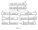
- FIG. 7 is a block diagram of the steps of a process that may be used to form the gas turbine vane of FIG. 1 .
- FIG. 1 A gas turbine vane component 10 having a ceramic matrix composite (CMC) airfoil member 12 integrally bonded to at least one shroud or platform member 14 is illustrated in FIG. 1 .
- the airfoil member 12 and the platform member 14 are bonded to each other along respective joint surfaces 16 , 18 , as may be better seen in the various embodiments of FIGS. 2-6, to form an integral vane component 10 .
- CMC ceramic matrix composite
- FIG. 2 illustrates one embodiment of turbine vane 10 wherein airfoil member 12 and platform 14 are bonded with an adhesive 20 , for example a high temperature ceramic adhesive such as from Cotronics (Resbond 989 or 904), Aremco (Ceramabond 503, 600, or 516), Sauerizon (phosphate based adhesives), or Zircar (ZR-COM) or variations on these basic adhesive types.
- the airfoil member 12 and the platform member 14 may each be formed separately of CMC materials using processes well known in the art.
- the ceramics utilized for the CMC material may be oxide or non-oxide materials, for example alumina, mullite, silcon carbide, etc.
- each of these components is a relatively simple shape, they may be formed using simplified tooling and fabrication methods.
- the airfoil member is formed to the green body state at step 22 of FIG. 7 and the platform member is formed to the green body state at step 24 .
- the terms green body and green body state are used herein to include stages of processing from still-wet perform to the semi-fired state where the parts are rigid enough to be self-supporting.
- the airfoil member 12 and/or the platform member 14 may be produced from a plurality of individual parts that are bonded or joined together in any variety of ways, or they may be formed as single-piece parts. For the embodiment of FIG.
- each of the green body parts are first cured to a final density at step 26 in order to allow shrinkage to occur prior to bonding, so that close tolerance fits can be maintained and so that residual stresses can be minimized.
- the joint surface 16 of the airfoil member 12 is then bonded to the joint surface 18 of the platform member 14 by a layer of adhesive 20 at step 28 .
- the adhesive may be applied in accordance with known procedures and in accordance with the adhesive manufacturer's instructions. Note that the geometry of the adhesive joint may be designed to place the adhesive 20 in a relatively cooler area of the component when compared to areas exposed most directly to the hot combustion gasses.
- FIG. 3 illustrates another embodiment of a bond 30 between the airfoil member 12 and the platform member 14 .
- the bond 30 is a sinter bond formed at step 32 by urging the respective joint surfaces 16 , 18 of the green body airfoil member 12 and platform member 14 together at a firing temperature.
- firing temperature is used herein to mean a temperature sufficiently high to cause curing, densification and sintering of the green body CMC materials to a final cured state.
- a typical firing temperature of 1,200-1,400 ° C. may be used for 1 - 5 hours to cure an alumina-based CMC material.
- the bond 30 provides a solid joint between the airfoil member 12 and platform member 14 without the need for special pre-form lay-up procedures.
- the bond 30 of the embodiment of FIG. 3 is further enhanced by the tapered joint geometry 34 .
- the joint surface 18 of platform member 14 is formed to include opposed sides that are disposed in a non-parallel orientation to define a tapered opening.
- the joint surface 16 of airfoil member 12 is similarly formed to include opposes sides that are disposed in a non-parallel orientation corresponding to the orientation of the platform member joint surface 18 .
- the airfoil member joint surface 16 is inserted into the platform member tapered opening so that the respective joint surfaces 16 , 18 are urged together during the curing process to form the sinter bond 30 .
- an adhesive joint may be utilized in lieu of the sinter bond 30 with a tapered joint geometry 34 .
- FIG. 4 illustrates another embodiment of a vane 10 wherein airfoil member 12 are joined to form an integral component by a bond such as sinter bond 30 , and that bond 30 is reinforced at step 36 by a reinforcing member such as a mechanical fastener 38 .
- the mechanical fastener 38 may be a bolt, clamp, pin, spring member, etc., and it may be formed of any compatible material such as a metal alloy or composite material such as a CMC material.
- the fastener 38 serves to provide compressive force between respective joint surfaces 16 , 18 and/or to function as a shear pin to resist sliding motion there between.
- the fastener 38 may be used to hold the airfoil member 12 and platform 14 together during the step 32 of forming the sinter bond 30 .
- the fastener 38 may be used to secure the parts while the adhesive cures at step 28 and may thus be integrally bonded to both parts.
- FIG. 5 illustrates another embodiment of a vane 10 having a joint 40 between airfoil member 12 and platform 14 wherein a CMC doubler reinforcing member 42 is placed across the joint 40 to reinforce the bond between the respective joint surfaces 16 , 18 .
- the airfoil member 12 and platform member 14 are formed of a CMC material in a green body shape, then doubler 42 is formed in a CMC green body shape to have a generally U-shaped cross-section with opposed legs 44 , 46 disposed on opposes sides of joint 40 .
- the entire assembly is then exposed to a firing temperature to co-cure and to sinter the entire joint 40 into an integral part.
- FIG. 6 illustrates a further embodiment of a vane 10 wherein joint 40 includes a shear pin 48 that is retained in position by generally U-shaped reinforcing member 42 .
- each of the airfoil member 12 , platform member 14 , reinforcing member 42 and shear pin 48 may be formed of CMC materials that are brought together in their green body state and then co-fired to form an integral vane component 10 .
- the joint 30 , 40 may be formed at step 50 through the co-infiltration of the assembled subcomponents 12 , 14 , 42 , 48 .
- This approach may also be used in conjunction with the co-curing method to further strengthen the joint that was previously made by a sinter bond.
- the infiltrate may be the original matrix material (slurry, sol-gel, polymer precursor, etc.) or a subset of the original matrix (e.g. the solution minus the particulate additives).
Abstract
Description
Claims (34)
Priority Applications (3)
| Application Number | Priority Date | Filing Date | Title |
|---|---|---|---|
| US10/158,966 US6648597B1 (en) | 2002-05-31 | 2002-05-31 | Ceramic matrix composite turbine vane |
| EP03010780.9A EP1367037B1 (en) | 2002-05-31 | 2003-05-14 | Ceramic matrix composite turbine vane |
| CA2430050A CA2430050C (en) | 2002-05-31 | 2003-05-29 | Ceramic matrix composite turbine vane |
Applications Claiming Priority (1)
| Application Number | Priority Date | Filing Date | Title |
|---|---|---|---|
| US10/158,966 US6648597B1 (en) | 2002-05-31 | 2002-05-31 | Ceramic matrix composite turbine vane |
Publications (1)
| Publication Number | Publication Date |
|---|---|
| US6648597B1 true US6648597B1 (en) | 2003-11-18 |
Family
ID=29419688
Family Applications (1)
| Application Number | Title | Priority Date | Filing Date |
|---|---|---|---|
| US10/158,966 Expired - Lifetime US6648597B1 (en) | 2002-05-31 | 2002-05-31 | Ceramic matrix composite turbine vane |
Country Status (3)
| Country | Link |
|---|---|
| US (1) | US6648597B1 (en) |
| EP (1) | EP1367037B1 (en) |
| CA (1) | CA2430050C (en) |
Cited By (157)
| Publication number | Priority date | Publication date | Assignee | Title |
|---|---|---|---|---|
| US20040115395A1 (en) * | 2002-12-13 | 2004-06-17 | General Electric Company | Assembly containing a composite article and assembly method therefor |
| US20040120808A1 (en) * | 2002-12-20 | 2004-06-24 | Alford Mary Ellen | Shroud segment and assembly with surface recessed seal bridging adjacent members |
| US20040120806A1 (en) * | 2002-12-20 | 2004-06-24 | Darkins Toby George | Shroud segment and assembly with circumferential seal at a planar segment surface |
| US20050129514A1 (en) * | 2003-06-30 | 2005-06-16 | Snecma Moteurs | Nozzle ring with adhesive bonded blading for aircraft engine compressor |
| US20050254942A1 (en) * | 2002-09-17 | 2005-11-17 | Siemens Westinghouse Power Corporation | Method of joining ceramic parts and articles so formed |
| FR2871847A1 (en) * | 2004-06-17 | 2005-12-23 | Snecma Moteurs Sa | MOUNTING A TURBINE DISPENSER ON A COMBUSTION CHAMBER WITH CMC WALLS IN A GAS TURBINE |
| US20060039793A1 (en) * | 2003-10-27 | 2006-02-23 | Holger Grote | Turbine blade for use in a gas turbine |
| US20060171812A1 (en) * | 2005-02-02 | 2006-08-03 | Siemens Westinghouse Power Corporation | Support system for a composite airfoil in a turbine engine |
| US20060211564A1 (en) * | 2005-03-16 | 2006-09-21 | Siemens Westinghouse Power Corporation | Ceramic matrix composite utilizing partially stabilized fibers |
| US20060228211A1 (en) * | 2005-04-07 | 2006-10-12 | Siemens Westinghouse Power Corporation | Multi-piece turbine vane assembly |
| US20060226290A1 (en) * | 2005-04-07 | 2006-10-12 | Siemens Westinghouse Power Corporation | Vane assembly with metal trailing edge segment |
| US20070031258A1 (en) * | 2005-08-04 | 2007-02-08 | Siemens Westinghouse Power Corporation | Pin-loaded mounting apparatus for a refractory component in a combustion turbine engine |
| US20070065676A1 (en) * | 2005-09-16 | 2007-03-22 | Bacalski Carlos F | Inert processing of oxide ceramic matrix composites and oxidation sensitive ceramic materials and intermediate structures and articles incorporating same |
| US20070128043A1 (en) * | 2005-01-21 | 2007-06-07 | Siemens Westinghouse Power Corporation | Cmc component and method of fabrication |
| US20070160466A1 (en) * | 2006-01-12 | 2007-07-12 | Siemens Power Generation, Inc. | CMC turbine shroud ring segment and fabrication method |
| JP2007182881A (en) * | 2006-01-03 | 2007-07-19 | General Electric Co <Ge> | Gas turbine stator and turbine blade assembly |
| JP2007255224A (en) * | 2006-03-20 | 2007-10-04 | Mitsubishi Heavy Ind Ltd | Turbine blade and gas turbine |
| US20070258811A1 (en) * | 2006-05-03 | 2007-11-08 | United Technologies Corporation | Ceramic matrix composite turbine engine vane |
| US20080115484A1 (en) * | 2004-09-29 | 2008-05-22 | Eric Conete | Mixer For Separate-Stream Nozzle |
| US20080178465A1 (en) * | 2007-01-25 | 2008-07-31 | Siemens Power Generation, Inc. | CMC to metal attachment mechanism |
| US20080279679A1 (en) * | 2007-05-09 | 2008-11-13 | Siemens Power Generation, Inc. | Multivane segment mounting arrangement for a gas turbine |
| US20090003993A1 (en) * | 2007-06-28 | 2009-01-01 | United Technologies Corporation | Ceramic matrix composite turbine engine vane |
| US20090014926A1 (en) * | 2007-07-09 | 2009-01-15 | Siemens Power Generation, Inc. | Method of constructing a hollow fiber reinforced structure |
| US20090208752A1 (en) * | 2008-02-14 | 2009-08-20 | United Technologies Corporation | Low transient and steady state thermal stress disk shaped components |
| US20100021290A1 (en) * | 2007-06-28 | 2010-01-28 | United Techonologies Corporation | Ceramic matrix composite turbine engine vane |
| US20100062210A1 (en) * | 2008-09-11 | 2010-03-11 | Marini Bonnie D | Ceramic matrix composite structure |
| US20100068034A1 (en) * | 2008-09-18 | 2010-03-18 | Schiavo Anthony L | CMC Vane Assembly Apparatus and Method |
| US20100189556A1 (en) * | 2009-01-28 | 2010-07-29 | United Technologies Corporation | Segmented ceramic matrix composite turbine airfoil component |
| JP2010180827A (en) * | 2009-02-06 | 2010-08-19 | Mitsubishi Heavy Ind Ltd | Gas turbine blade and gas turbine |
| WO2010110327A1 (en) | 2009-03-26 | 2010-09-30 | 株式会社Ihi | Cmc turbine stator vane |
| US20100279072A1 (en) * | 2009-04-29 | 2010-11-04 | Siemens Energy, Inc. | Gussets for Strengthening CMC Fillet Radii |
| US20110008156A1 (en) * | 2009-07-08 | 2011-01-13 | Ian Francis Prentice | Composite turbine nozzle |
| US20110041313A1 (en) * | 2009-08-24 | 2011-02-24 | James Allister W | Joining Mechanism with Stem Tension and Interlocked Compression Ring |
| US20110081240A1 (en) * | 2009-10-01 | 2011-04-07 | Pratt & Whitney Canada Corp. | Fabricated gas turbine vane ring |
| US8007242B1 (en) | 2009-03-16 | 2011-08-30 | Florida Turbine Technologies, Inc. | High temperature turbine rotor blade |
| US20110229337A1 (en) * | 2004-01-15 | 2011-09-22 | General Electric Company | Hybrid ceramic matrix composite turbine blades for improved processibility and performance and process for producing hybrid turbine blades |
| US20110243724A1 (en) * | 2010-04-01 | 2011-10-06 | Campbell Christian X | Turbine airfoil to shround attachment |
| US8061977B2 (en) | 2007-07-03 | 2011-11-22 | Siemens Energy, Inc. | Ceramic matrix composite attachment apparatus and method |
| US20110297344A1 (en) * | 2010-04-01 | 2011-12-08 | Campbell Christian X | Turbine airfoil to shroud attachment method |
| US20120057985A1 (en) * | 2009-03-26 | 2012-03-08 | Ihi Corporation | Cmc turbine stator blade |
| WO2012109421A1 (en) | 2011-02-09 | 2012-08-16 | Siemens Energy, Inc. | Joining mechanism and method for interlocking modular turbine engine component with a split ring |
| US8262345B2 (en) | 2009-02-06 | 2012-09-11 | General Electric Company | Ceramic matrix composite turbine engine |
| CN102678187A (en) * | 2011-03-07 | 2012-09-19 | 通用电气公司 | Turbine bucket for use in gas turbine engines and methods for fabricating the same |
| US8347636B2 (en) | 2010-09-24 | 2013-01-08 | General Electric Company | Turbomachine including a ceramic matrix composite (CMC) bridge |
| US8382436B2 (en) | 2009-01-06 | 2013-02-26 | General Electric Company | Non-integral turbine blade platforms and systems |
| US20130089416A1 (en) * | 2011-10-07 | 2013-04-11 | Pratt & Whitney Canada Corp. | Fabricated gas turbine duct |
| US20130089431A1 (en) * | 2011-10-07 | 2013-04-11 | General Electric Company | Airfoil for turbine system |
| US20130154194A1 (en) * | 2010-09-03 | 2013-06-20 | Borgwarner Inc. | Turbocharger housing seal |
| US20130189110A1 (en) * | 2010-09-29 | 2013-07-25 | Stephen Batt | Turbine arrangement and gas turbine engine |
| US8511975B2 (en) | 2011-07-05 | 2013-08-20 | United Technologies Corporation | Gas turbine shroud arrangement |
| WO2013141941A1 (en) * | 2011-12-30 | 2013-09-26 | Rolls-Royce Corporation | Turbine engine and vane system |
| WO2013154007A1 (en) | 2012-04-10 | 2013-10-17 | 株式会社Ihi | Method for manufacturing coupled turbine blades, and coupled turbine blades |
| US8616801B2 (en) | 2010-04-29 | 2013-12-31 | Siemens Energy, Inc. | Gusset with fibers oriented to strengthen a CMC wall intersection anisotropically |
| EP2728125A1 (en) * | 2012-11-02 | 2014-05-07 | Rolls-Royce plc | Method of forming a ceramic matrix composite component and corresponding ceramic matrix composite gas turbine engine component |
| US8739547B2 (en) | 2011-06-23 | 2014-06-03 | United Technologies Corporation | Gas turbine engine joint having a metallic member, a CMC member, and a ceramic key |
| US20140193270A1 (en) * | 2013-01-08 | 2014-07-10 | Coi Ceramics, Inc. | Ceramic composite matrix material bonded assembly and processes thereof |
| US20140199174A1 (en) * | 2013-01-11 | 2014-07-17 | General Electric Company | Method of forming a ceramic matrix composite component, a ceramic matrix composite component and a tip member |
| US8790067B2 (en) | 2011-04-27 | 2014-07-29 | United Technologies Corporation | Blade clearance control using high-CTE and low-CTE ring members |
| US20140212292A1 (en) * | 2012-12-18 | 2014-07-31 | United Technologies Corporation | Airfoil Member and Composite Platform Having Contoured Endwall |
| US20140241883A1 (en) * | 2013-02-23 | 2014-08-28 | Rolls-Royce Corporation | Gas turbine engine component |
| US20140248156A1 (en) * | 2012-12-21 | 2014-09-04 | United Technologies Corporation | Composite Articles and Methods |
| US20140255174A1 (en) * | 2012-12-21 | 2014-09-11 | United Technologies Corporation | Manufacture of full ring strut vane pack |
| US8864492B2 (en) | 2011-06-23 | 2014-10-21 | United Technologies Corporation | Reverse flow combustor duct attachment |
| US8920127B2 (en) | 2011-07-18 | 2014-12-30 | United Technologies Corporation | Turbine rotor non-metallic blade attachment |
| CN104271534A (en) * | 2012-03-22 | 2015-01-07 | 圣戈本陶瓷及塑料股份有限公司 | Sinter-bonded ceramic articles |
| US20150016972A1 (en) * | 2013-03-14 | 2015-01-15 | Rolls-Royce North American Technologies, Inc. | Bi-cast turbine vane |
| WO2015009388A1 (en) * | 2013-07-19 | 2015-01-22 | United Technologies Corporation | Gas turbine engine ceramic component assembly and bonding |
| WO2015009386A1 (en) | 2013-07-18 | 2015-01-22 | United Technologies Corporation | Gas turbine engine ceramic component assembly attachment |
| US20150064018A1 (en) * | 2012-03-29 | 2015-03-05 | Siemens Aktiengesellschaft | Turbine blade and associated method for producing a turbine blade |
| US20150071783A1 (en) * | 2012-03-29 | 2015-03-12 | Siemens Aktiengesellschaft | Turbine blade |
| US20150093249A1 (en) * | 2013-09-30 | 2015-04-02 | MTU Aero Engines AG | Blade for a gas turbine |
| WO2015047485A3 (en) * | 2013-07-29 | 2015-06-18 | United Technologies Corporation | Gas turbine engine cmc airfoil assembly |
| US9121365B1 (en) | 2014-04-17 | 2015-09-01 | Achates Power, Inc. | Liner component for a cylinder of an opposed-piston engine |
| US20150292540A1 (en) * | 2014-04-09 | 2015-10-15 | Natel Energy, Inc. | Wedge clamping system for beams |
| US9249669B2 (en) | 2012-04-05 | 2016-02-02 | General Electric Company | CMC blade with pressurized internal cavity for erosion control |
| US20160032735A1 (en) * | 2013-03-15 | 2016-02-04 | United Technologies Corporation | Transient liquid phase bonded tip shroud |
| US9290311B2 (en) | 2012-03-22 | 2016-03-22 | Saint-Gobain Ceramics & Plastics, Inc. | Sealed containment tube |
| US9335051B2 (en) | 2011-07-13 | 2016-05-10 | United Technologies Corporation | Ceramic matrix composite combustor vane ring assembly |
| US20160177749A1 (en) * | 2014-12-19 | 2016-06-23 | Alstom Technology Ltd | Blading member for a fluid flow machine |
| US9376916B2 (en) | 2012-06-05 | 2016-06-28 | United Technologies Corporation | Assembled blade platform |
| US9458726B2 (en) | 2013-03-13 | 2016-10-04 | Rolls-Royce Corporation | Dovetail retention system for blade tracks |
| US20160348528A1 (en) * | 2015-05-26 | 2016-12-01 | Daniel Kent Vetters | Ceramic matrix composite seal segment for a gas turbine engine |
| US9527262B2 (en) | 2012-09-28 | 2016-12-27 | General Electric Company | Layered arrangement, hot-gas path component, and process of producing a layered arrangement |
| US20170074110A1 (en) * | 2014-03-06 | 2017-03-16 | Herakles | Stator sector for a turbine engine, and a method of fabricating it |
| US20170254212A1 (en) * | 2014-08-27 | 2017-09-07 | Safran Aircraft Engines | A guide vane made of composite material for a gas turbine engine, and it's method of fabrication |
| US9759082B2 (en) | 2013-03-12 | 2017-09-12 | Rolls-Royce Corporation | Turbine blade track assembly |
| CN107266099A (en) * | 2017-06-16 | 2017-10-20 | 中国人民解放军第五七九工厂 | A kind of aero-engine ceramic matrix composite turbine stator blade near-net-shape fixture |
| US9938900B2 (en) | 2011-05-26 | 2018-04-10 | United Technologies Corporation | Ceramic matrix composite turbine exhaust case for a gas turbine engine |
| US9970307B2 (en) | 2014-03-19 | 2018-05-15 | Honeywell International Inc. | Turbine nozzles with slip joints impregnated by oxidation-resistant sealing material and methods for the production thereof |
| US20180135421A1 (en) * | 2016-11-17 | 2018-05-17 | United Technologies Corporation | Airfoil with panel fastened to core structure |
| US20180135452A1 (en) * | 2016-11-17 | 2018-05-17 | United Technologies Corporation | Airfoil with panel having perimeter seal |
| GB2556202A (en) * | 2016-10-12 | 2018-05-23 | Safran Aircraft Engines | Vane comprising an assembled platform and blade |
| US9995417B2 (en) | 2012-03-22 | 2018-06-12 | Saint-Gobain Ceramics & Plastics, Inc. | Extended length tube structures |
| US20180223680A1 (en) * | 2017-02-06 | 2018-08-09 | General Electric Company | Nozzle assembly and method for forming nozzle assembly |
| US20180340440A1 (en) * | 2017-05-23 | 2018-11-29 | Rolls-Royce North American Technologies Inc. | Turbine shroud assembly having ceramic matrix composite track segments with metallic attachment features |
| US10174619B2 (en) | 2013-03-08 | 2019-01-08 | Rolls-Royce North American Technologies Inc. | Gas turbine engine composite vane assembly and method for making same |
| US20190040746A1 (en) * | 2017-08-07 | 2019-02-07 | General Electric Company | Cmc blade with internal support |
| US10207471B2 (en) * | 2016-05-04 | 2019-02-19 | General Electric Company | Perforated ceramic matrix composite ply, ceramic matrix composite article, and method for forming ceramic matrix composite article |
| CN109424371A (en) * | 2017-08-30 | 2019-03-05 | 通用电气公司 | Flow path component and its assemble method for gas-turbine unit |
| US10260362B2 (en) | 2017-05-30 | 2019-04-16 | Rolls-Royce Corporation | Turbine vane assembly with ceramic matrix composite airfoil and friction fit metallic attachment features |
| CN110080825A (en) * | 2013-04-29 | 2019-08-02 | 通用电气公司 | Composite article and production method including composite material to metal interlock |
| US10415430B2 (en) * | 2016-04-05 | 2019-09-17 | MTU Aero Engines AG | Coupling assembly for components of ceramic matrix composites for a turbine center frame |
| JP2019194474A (en) * | 2018-05-02 | 2019-11-07 | ゼネラル・エレクトリック・カンパニイ | Cmc nozzle with interlocking mechanical joint and fabrication |
| US10577953B2 (en) | 2014-07-14 | 2020-03-03 | Ihi Corporation | Turbine stator vane of ceramic matrix composite |
| US10590798B2 (en) | 2013-03-25 | 2020-03-17 | United Technologies Corporation | Non-integral blade and platform segment for rotor |
| US10590786B2 (en) | 2016-05-03 | 2020-03-17 | General Electric Company | System and method for cooling components of a gas turbine engine |
| US20200095877A1 (en) * | 2018-09-26 | 2020-03-26 | Rolls-Royce Corporation | Anti-fret liner |
| US10605103B2 (en) | 2018-08-24 | 2020-03-31 | Rolls-Royce Corporation | CMC airfoil assembly |
| CN111059077A (en) * | 2018-10-16 | 2020-04-24 | 通用电气公司 | Fragile gas turbine engine airfoil with fused cavity |
| US20200248568A1 (en) * | 2019-02-01 | 2020-08-06 | Rolls-Royce Plc | Turbine vane assembly with ceramic matrix composite components and temperature management features |
| US10738628B2 (en) * | 2018-05-25 | 2020-08-11 | General Electric Company | Joint for band features on turbine nozzle and fabrication |
| US10767497B2 (en) | 2018-09-07 | 2020-09-08 | Rolls-Royce Corporation | Turbine vane assembly with ceramic matrix composite components |
| US10767493B2 (en) | 2019-02-01 | 2020-09-08 | Rolls-Royce Plc | Turbine vane assembly with ceramic matrix composite vanes |
| US10781708B2 (en) * | 2014-08-26 | 2020-09-22 | Safran Aircraft Engines | Guide vane made from composite material, comprising staggered attachment flanges for a gas turbine engine |
| US10794205B2 (en) | 2017-02-27 | 2020-10-06 | Rolls-Royce North American Technologies Inc. | Ceramic seal component for gas turbine engine and process of making the same |
| US10830063B2 (en) | 2018-07-20 | 2020-11-10 | Rolls-Royce North American Technologies Inc. | Turbine vane assembly with ceramic matrix composite components |
| US10859268B2 (en) | 2018-10-03 | 2020-12-08 | Rolls-Royce Plc | Ceramic matrix composite turbine vanes and vane ring assemblies |
| US10883376B2 (en) | 2019-02-01 | 2021-01-05 | Rolls-Royce Plc | Turbine vane assembly with ceramic matrix composite vanes |
| US10890076B1 (en) | 2019-06-28 | 2021-01-12 | Rolls-Royce Plc | Turbine vane assembly having ceramic matrix composite components with expandable spar support |
| IT201900011760A1 (en) * | 2019-07-15 | 2021-01-15 | Petroceramics S P A | METHOD FOR MAKING A COMPONENT IN FIBER-REINFORCED COMPOSITE MATERIAL |
| US10934870B2 (en) | 2018-09-17 | 2021-03-02 | Rolls Royce Plc | Turbine vane assembly with reinforced end wall joints |
| US10954802B2 (en) | 2019-04-23 | 2021-03-23 | Rolls-Royce Plc | Turbine section assembly with ceramic matrix composite vane |
| US10961857B2 (en) | 2018-12-21 | 2021-03-30 | Rolls-Royce Plc | Turbine section of a gas turbine engine with ceramic matrix composite vanes |
| US10975708B2 (en) | 2019-04-23 | 2021-04-13 | Rolls-Royce Plc | Turbine section assembly with ceramic matrix composite vane |
| US11008888B2 (en) * | 2018-07-17 | 2021-05-18 | Rolls-Royce Corporation | Turbine vane assembly with ceramic matrix composite components |
| US11008880B2 (en) | 2019-04-23 | 2021-05-18 | Rolls-Royce Plc | Turbine section assembly with ceramic matrix composite vane |
| EP3825519A1 (en) * | 2019-11-21 | 2021-05-26 | Raytheon Technologies Corporation | Vane with collar |
| US11041394B2 (en) | 2018-06-01 | 2021-06-22 | Rolls-Royce Corporation | CMC airfoil joint |
| US11047247B2 (en) | 2018-12-21 | 2021-06-29 | Rolls-Royce Plc | Turbine section of a gas turbine engine with ceramic matrix composite vanes |
| US11118481B2 (en) | 2017-02-06 | 2021-09-14 | Raytheon Technologies Corporation | Ceramic matrix composite turbine exhaust assembly for a gas turbine engine |
| US11149559B2 (en) * | 2019-05-13 | 2021-10-19 | Rolls-Royce Plc | Turbine section assembly with ceramic matrix composite vane |
| US11149568B2 (en) | 2018-12-20 | 2021-10-19 | Rolls-Royce Plc | Sliding ceramic matrix composite vane assembly for gas turbine engines |
| US11149590B2 (en) | 2017-06-21 | 2021-10-19 | Rolls-Royce Corporation | Ceramic matrix composite joints |
| US11149567B2 (en) | 2018-09-17 | 2021-10-19 | Rolls-Royce Corporation | Ceramic matrix composite load transfer roller joint |
| US11162372B2 (en) | 2019-12-04 | 2021-11-02 | Rolls-Royce Plc | Turbine vane doublet with ceramic matrix composite material construction |
| US11162377B2 (en) * | 2019-05-31 | 2021-11-02 | Rolls-Royce High Temperature Composites Inc. | Ceramic matrix composite turbine vane and method for making |
| US11193381B2 (en) | 2019-05-17 | 2021-12-07 | Rolls-Royce Plc | Turbine vane assembly having ceramic matrix composite components with sliding support |
| US11193393B2 (en) | 2019-04-23 | 2021-12-07 | Rolls-Royce Plc | Turbine section assembly with ceramic matrix composite vane |
| US11286798B2 (en) * | 2019-08-20 | 2022-03-29 | Rolls-Royce Corporation | Airfoil assembly with ceramic matrix composite parts and load-transfer features |
| US11319822B2 (en) | 2020-05-06 | 2022-05-03 | Rolls-Royce North American Technologies Inc. | Hybrid vane segment with ceramic matrix composite airfoils |
| US20220136397A1 (en) * | 2020-10-30 | 2022-05-05 | General Electric Company | Fabricated cmc nozzle assemblies for gas turbine engines |
| US11333037B2 (en) | 2020-02-06 | 2022-05-17 | Raytheon Technologies Corporation | Vane arc segment load path |
| US20220162945A1 (en) * | 2020-11-24 | 2022-05-26 | Raytheon Technologies Corporation | Vane arc segment with thermal insulation element |
| US11352887B2 (en) * | 2016-04-15 | 2022-06-07 | General Electric Company | Airfoil cooling using non-line of sight holes |
| US11415013B1 (en) * | 2021-09-30 | 2022-08-16 | Rolls-Royce Plc | Ceramic matrix composite vane with integrated platform joint |
| US11434177B2 (en) * | 2019-05-13 | 2022-09-06 | Rolls-Royce Plc | Ceramic matrix composite vane with hybrid construction |
| US11454128B2 (en) * | 2018-08-06 | 2022-09-27 | General Electric Company | Fairing assembly |
| US20220341339A1 (en) * | 2020-03-13 | 2022-10-27 | General Electric Company | Nozzle assembly with alternating inserted vanes for a turbine engine |
| US11486256B2 (en) | 2020-12-07 | 2022-11-01 | Raytheon Technologies Corporation | Vane arc segment with conformal thermal insulation blanket |
| US11555451B2 (en) * | 2020-11-23 | 2023-01-17 | Raytheon Technologies Corporation | Ceramic article with thermal insulation bushing |
| US11560799B1 (en) | 2021-10-22 | 2023-01-24 | Rolls-Royce High Temperature Composites Inc. | Ceramic matrix composite vane assembly with shaped load transfer features |
| US11702948B2 (en) | 2018-03-14 | 2023-07-18 | General Electric Company | CMC shroud segment with interlocking mechanical joints and fabrication |
| US11732596B2 (en) | 2021-12-22 | 2023-08-22 | Rolls-Royce Plc | Ceramic matrix composite turbine vane assembly having minimalistic support spars |
| US11802486B2 (en) * | 2017-11-13 | 2023-10-31 | General Electric Company | CMC component and fabrication using mechanical joints |
| US11890682B2 (en) | 2020-06-15 | 2024-02-06 | Rolls-Royce Corporation | Semi-compliant fasteners for mechanical locking |
| US20240044258A1 (en) * | 2022-08-05 | 2024-02-08 | Raytheon Technologies Corporation | Vane multiplet with conjoined singlet vanes |
| US11952917B2 (en) * | 2022-08-05 | 2024-04-09 | Rtx Corporation | Vane multiplet with conjoined singlet vanes |
Families Citing this family (10)
| Publication number | Priority date | Publication date | Assignee | Title |
|---|---|---|---|---|
| US8850823B2 (en) | 2009-12-29 | 2014-10-07 | Rolls-Royce North American Technologies, Inc. | Integrated aero-engine flowpath structure |
| US9212560B2 (en) † | 2011-06-30 | 2015-12-15 | United Technologies Corporation | CMC blade with integral 3D woven platform |
| CN105188996A (en) * | 2013-02-28 | 2015-12-23 | 戴蒙得创新股份有限公司 | CVI bonded and coated PCBN to WC tool body |
| GB201319366D0 (en) * | 2013-11-01 | 2013-12-18 | Mbda Uk Ltd | Method of manufacturing ceramic matrix composite objects |
| ES2848077T3 (en) | 2013-11-01 | 2021-08-05 | Mbda Uk Ltd | Manufacturing method of ceramic matrix composite objects |
| US10538013B2 (en) | 2014-05-08 | 2020-01-21 | United Technologies Corporation | Integral ceramic matrix composite fastener with non-polymer rigidization |
| US10371011B2 (en) * | 2014-05-08 | 2019-08-06 | United Technologies Corporation | Integral ceramic matrix composite fastener with polymer rigidization |
| EP3109043B1 (en) | 2015-06-22 | 2018-01-31 | Rolls-Royce Corporation | Method for integral joining infiltrated ceramic matrix composites |
| WO2019240754A2 (en) * | 2018-06-11 | 2019-12-19 | Siemens Aktiengesellschaft | Composite ceramic and metallic vane for combustion turbine engine |
| US11448080B2 (en) | 2020-02-13 | 2022-09-20 | Raytheon Technologies Corporation | Guide vane for a gas turbine engine and method for testing a bond seal of a guide vane for a gas turbine engine |
Citations (42)
| Publication number | Priority date | Publication date | Assignee | Title |
|---|---|---|---|---|
| US3910716A (en) | 1974-05-23 | 1975-10-07 | Westinghouse Electric Corp | Gas turbine inlet vane structure utilizing a stable ceramic spherical interface arrangement |
| US4076451A (en) * | 1976-03-05 | 1978-02-28 | United Technologies Corporation | Ceramic turbine stator |
| US4365933A (en) * | 1978-11-16 | 1982-12-28 | Volkswagenwerk Aktienbesellschaft | Axial vane ring consisting of ceramic materials for gas turbines |
| US4396349A (en) | 1981-03-16 | 1983-08-02 | Motoren-Und Turbinen-Union Munchen Gmbh | Turbine blade, more particularly turbine nozzle vane, for gas turbine engines |
| US4519745A (en) | 1980-09-19 | 1985-05-28 | Rockwell International Corporation | Rotor blade and stator vane using ceramic shell |
| US4530884A (en) | 1976-04-05 | 1985-07-23 | Brunswick Corporation | Ceramic-metal laminate |
| US4563125A (en) | 1982-12-15 | 1986-01-07 | Office National D'etudes Et De Recherches Aerospatiales | Ceramic blades for turbomachines |
| US4563128A (en) | 1983-02-26 | 1986-01-07 | Mtu Motoren-Und Turbinen-Union Muenchen Gmbh | Ceramic turbine blade having a metal support core |
| US4629397A (en) | 1983-07-28 | 1986-12-16 | Mtu Motoren-Und Turbinen-Union Muenchen Gmbh | Structural component for use under high thermal load conditions |
| US4639189A (en) | 1984-02-27 | 1987-01-27 | Rockwell International Corporation | Hollow, thermally-conditioned, turbine stator nozzle |
| US4643636A (en) | 1985-07-22 | 1987-02-17 | Avco Corporation | Ceramic nozzle assembly for gas turbine engine |
| US4645421A (en) | 1985-06-19 | 1987-02-24 | Mtu Motoren-Und Turbinen-Union Muenchen Gmbh | Hybrid vane or blade for a fluid flow engine |
| US4768924A (en) | 1986-07-22 | 1988-09-06 | Pratt & Whitney Canada Inc. | Ceramic stator vane assembly |
| US4790721A (en) | 1988-04-25 | 1988-12-13 | Rockwell International Corporation | Blade assembly |
| US4838031A (en) | 1987-08-06 | 1989-06-13 | Avco Corporation | Internally cooled combustion chamber liner |
| US4907946A (en) | 1988-08-10 | 1990-03-13 | General Electric Company | Resiliently mounted outlet guide vane |
| US5027604A (en) | 1986-05-06 | 1991-07-02 | Mtu Motoren- Und Turbinen Union Munchen Gmbh | Hot gas overheat protection device for gas turbine engines |
| US5226789A (en) | 1991-05-13 | 1993-07-13 | General Electric Company | Composite fan stator assembly |
| US5306554A (en) | 1989-04-14 | 1994-04-26 | General Electric Company | Consolidated member and method and preform for making |
| US5314309A (en) | 1990-05-25 | 1994-05-24 | Anthony Blakeley | Turbine blade with metallic attachment and method of making the same |
| US5328331A (en) | 1993-06-28 | 1994-07-12 | General Electric Company | Turbine airfoil with double shell outer wall |
| US5358379A (en) | 1993-10-27 | 1994-10-25 | Westinghouse Electric Corporation | Gas turbine vane |
| US5375978A (en) | 1992-05-01 | 1994-12-27 | General Electric Company | Foreign object damage resistant composite blade and manufacture |
| US5382453A (en) | 1992-09-02 | 1995-01-17 | Rolls-Royce Plc | Method of manufacturing a hollow silicon carbide fiber reinforced silicon carbide matrix component |
| US5484258A (en) | 1994-03-01 | 1996-01-16 | General Electric Company | Turbine airfoil with convectively cooled double shell outer wall |
| US5494402A (en) | 1994-05-16 | 1996-02-27 | Solar Turbines Incorporated | Low thermal stress ceramic turbine nozzle |
| US5493855A (en) | 1992-12-17 | 1996-02-27 | Alfred E. Tisch | Turbine having suspended rotor blades |
| US5584652A (en) | 1995-01-06 | 1996-12-17 | Solar Turbines Incorporated | Ceramic turbine nozzle |
| US5605046A (en) | 1995-10-26 | 1997-02-25 | Liang; George P. | Cooled liner apparatus |
| US5616001A (en) | 1995-01-06 | 1997-04-01 | Solar Turbines Incorporated | Ceramic cerami turbine nozzle |
| US5630700A (en) | 1996-04-26 | 1997-05-20 | General Electric Company | Floating vane turbine nozzle |
| US5640767A (en) | 1995-01-03 | 1997-06-24 | Gen Electric | Method for making a double-wall airfoil |
| US5720597A (en) | 1996-01-29 | 1998-02-24 | General Electric Company | Multi-component blade for a gas turbine |
| US5791879A (en) | 1996-05-20 | 1998-08-11 | General Electric Company | Poly-component blade for a gas turbine |
| US5820337A (en) | 1995-01-03 | 1998-10-13 | General Electric Company | Double wall turbine parts |
| US6000906A (en) | 1997-09-12 | 1999-12-14 | Alliedsignal Inc. | Ceramic airfoil |
| US6164903A (en) | 1998-12-22 | 2000-12-26 | United Technologies Corporation | Turbine vane mounting arrangement |
| US6197424B1 (en) | 1998-03-27 | 2001-03-06 | Siemens Westinghouse Power Corporation | Use of high temperature insulation for ceramic matrix composites in gas turbines |
| US6200092B1 (en) | 1999-09-24 | 2001-03-13 | General Electric Company | Ceramic turbine nozzle |
| US6241469B1 (en) | 1998-10-19 | 2001-06-05 | Asea Brown Boveri Ag | Turbine blade |
| US6325593B1 (en) | 2000-02-18 | 2001-12-04 | General Electric Company | Ceramic turbine airfoils with cooled trailing edge blocks |
| US6368663B1 (en) | 1999-01-28 | 2002-04-09 | Ishikawajima-Harima Heavy Industries Co., Ltd | Ceramic-based composite member and its manufacturing method |
Family Cites Families (3)
| Publication number | Priority date | Publication date | Assignee | Title |
|---|---|---|---|---|
| US4033792A (en) * | 1974-12-23 | 1977-07-05 | United Technologies Corporation | Composite single crystal article |
| US4501053A (en) * | 1982-06-14 | 1985-02-26 | United Technologies Corporation | Method of making rotor blade for a rotary machine |
| US5813832A (en) * | 1996-12-05 | 1998-09-29 | General Electric Company | Turbine engine vane segment |
-
2002
- 2002-05-31 US US10/158,966 patent/US6648597B1/en not_active Expired - Lifetime
-
2003
- 2003-05-14 EP EP03010780.9A patent/EP1367037B1/en not_active Expired - Fee Related
- 2003-05-29 CA CA2430050A patent/CA2430050C/en not_active Expired - Fee Related
Patent Citations (42)
| Publication number | Priority date | Publication date | Assignee | Title |
|---|---|---|---|---|
| US3910716A (en) | 1974-05-23 | 1975-10-07 | Westinghouse Electric Corp | Gas turbine inlet vane structure utilizing a stable ceramic spherical interface arrangement |
| US4076451A (en) * | 1976-03-05 | 1978-02-28 | United Technologies Corporation | Ceramic turbine stator |
| US4530884A (en) | 1976-04-05 | 1985-07-23 | Brunswick Corporation | Ceramic-metal laminate |
| US4365933A (en) * | 1978-11-16 | 1982-12-28 | Volkswagenwerk Aktienbesellschaft | Axial vane ring consisting of ceramic materials for gas turbines |
| US4519745A (en) | 1980-09-19 | 1985-05-28 | Rockwell International Corporation | Rotor blade and stator vane using ceramic shell |
| US4396349A (en) | 1981-03-16 | 1983-08-02 | Motoren-Und Turbinen-Union Munchen Gmbh | Turbine blade, more particularly turbine nozzle vane, for gas turbine engines |
| US4563125A (en) | 1982-12-15 | 1986-01-07 | Office National D'etudes Et De Recherches Aerospatiales | Ceramic blades for turbomachines |
| US4563128A (en) | 1983-02-26 | 1986-01-07 | Mtu Motoren-Und Turbinen-Union Muenchen Gmbh | Ceramic turbine blade having a metal support core |
| US4629397A (en) | 1983-07-28 | 1986-12-16 | Mtu Motoren-Und Turbinen-Union Muenchen Gmbh | Structural component for use under high thermal load conditions |
| US4639189A (en) | 1984-02-27 | 1987-01-27 | Rockwell International Corporation | Hollow, thermally-conditioned, turbine stator nozzle |
| US4645421A (en) | 1985-06-19 | 1987-02-24 | Mtu Motoren-Und Turbinen-Union Muenchen Gmbh | Hybrid vane or blade for a fluid flow engine |
| US4643636A (en) | 1985-07-22 | 1987-02-17 | Avco Corporation | Ceramic nozzle assembly for gas turbine engine |
| US5027604A (en) | 1986-05-06 | 1991-07-02 | Mtu Motoren- Und Turbinen Union Munchen Gmbh | Hot gas overheat protection device for gas turbine engines |
| US4768924A (en) | 1986-07-22 | 1988-09-06 | Pratt & Whitney Canada Inc. | Ceramic stator vane assembly |
| US4838031A (en) | 1987-08-06 | 1989-06-13 | Avco Corporation | Internally cooled combustion chamber liner |
| US4790721A (en) | 1988-04-25 | 1988-12-13 | Rockwell International Corporation | Blade assembly |
| US4907946A (en) | 1988-08-10 | 1990-03-13 | General Electric Company | Resiliently mounted outlet guide vane |
| US5306554A (en) | 1989-04-14 | 1994-04-26 | General Electric Company | Consolidated member and method and preform for making |
| US5314309A (en) | 1990-05-25 | 1994-05-24 | Anthony Blakeley | Turbine blade with metallic attachment and method of making the same |
| US5226789A (en) | 1991-05-13 | 1993-07-13 | General Electric Company | Composite fan stator assembly |
| US5375978A (en) | 1992-05-01 | 1994-12-27 | General Electric Company | Foreign object damage resistant composite blade and manufacture |
| US5382453A (en) | 1992-09-02 | 1995-01-17 | Rolls-Royce Plc | Method of manufacturing a hollow silicon carbide fiber reinforced silicon carbide matrix component |
| US5493855A (en) | 1992-12-17 | 1996-02-27 | Alfred E. Tisch | Turbine having suspended rotor blades |
| US5328331A (en) | 1993-06-28 | 1994-07-12 | General Electric Company | Turbine airfoil with double shell outer wall |
| US5358379A (en) | 1993-10-27 | 1994-10-25 | Westinghouse Electric Corporation | Gas turbine vane |
| US5484258A (en) | 1994-03-01 | 1996-01-16 | General Electric Company | Turbine airfoil with convectively cooled double shell outer wall |
| US5494402A (en) | 1994-05-16 | 1996-02-27 | Solar Turbines Incorporated | Low thermal stress ceramic turbine nozzle |
| US5820337A (en) | 1995-01-03 | 1998-10-13 | General Electric Company | Double wall turbine parts |
| US5640767A (en) | 1995-01-03 | 1997-06-24 | Gen Electric | Method for making a double-wall airfoil |
| US5584652A (en) | 1995-01-06 | 1996-12-17 | Solar Turbines Incorporated | Ceramic turbine nozzle |
| US5616001A (en) | 1995-01-06 | 1997-04-01 | Solar Turbines Incorporated | Ceramic cerami turbine nozzle |
| US5605046A (en) | 1995-10-26 | 1997-02-25 | Liang; George P. | Cooled liner apparatus |
| US5720597A (en) | 1996-01-29 | 1998-02-24 | General Electric Company | Multi-component blade for a gas turbine |
| US5630700A (en) | 1996-04-26 | 1997-05-20 | General Electric Company | Floating vane turbine nozzle |
| US5791879A (en) | 1996-05-20 | 1998-08-11 | General Electric Company | Poly-component blade for a gas turbine |
| US6000906A (en) | 1997-09-12 | 1999-12-14 | Alliedsignal Inc. | Ceramic airfoil |
| US6197424B1 (en) | 1998-03-27 | 2001-03-06 | Siemens Westinghouse Power Corporation | Use of high temperature insulation for ceramic matrix composites in gas turbines |
| US6241469B1 (en) | 1998-10-19 | 2001-06-05 | Asea Brown Boveri Ag | Turbine blade |
| US6164903A (en) | 1998-12-22 | 2000-12-26 | United Technologies Corporation | Turbine vane mounting arrangement |
| US6368663B1 (en) | 1999-01-28 | 2002-04-09 | Ishikawajima-Harima Heavy Industries Co., Ltd | Ceramic-based composite member and its manufacturing method |
| US6200092B1 (en) | 1999-09-24 | 2001-03-13 | General Electric Company | Ceramic turbine nozzle |
| US6325593B1 (en) | 2000-02-18 | 2001-12-04 | General Electric Company | Ceramic turbine airfoils with cooled trailing edge blocks |
Cited By (246)
| Publication number | Priority date | Publication date | Assignee | Title |
|---|---|---|---|---|
| US9068464B2 (en) | 2002-09-17 | 2015-06-30 | Siemens Energy, Inc. | Method of joining ceramic parts and articles so formed |
| US20050254942A1 (en) * | 2002-09-17 | 2005-11-17 | Siemens Westinghouse Power Corporation | Method of joining ceramic parts and articles so formed |
| US6830437B2 (en) * | 2002-12-13 | 2004-12-14 | General Electric Company | Assembly containing a composite article and assembly method therefor |
| US20040115395A1 (en) * | 2002-12-13 | 2004-06-17 | General Electric Company | Assembly containing a composite article and assembly method therefor |
| US20040120808A1 (en) * | 2002-12-20 | 2004-06-24 | Alford Mary Ellen | Shroud segment and assembly with surface recessed seal bridging adjacent members |
| US20040120806A1 (en) * | 2002-12-20 | 2004-06-24 | Darkins Toby George | Shroud segment and assembly with circumferential seal at a planar segment surface |
| US6808363B2 (en) * | 2002-12-20 | 2004-10-26 | General Electric Company | Shroud segment and assembly with circumferential seal at a planar segment surface |
| US6893214B2 (en) * | 2002-12-20 | 2005-05-17 | General Electric Company | Shroud segment and assembly with surface recessed seal bridging adjacent members |
| US7147434B2 (en) * | 2003-06-30 | 2006-12-12 | Snecma Moteurs | Nozzle ring with adhesive bonded blading for aircraft engine compressor |
| US20090148283A1 (en) * | 2003-06-30 | 2009-06-11 | Snecma Moteurs | Nozzle ring adhesive bonded blading for aircraft engine compressor |
| US7553130B1 (en) | 2003-06-30 | 2009-06-30 | Snecma | Nozzle ring adhesive bonded blading for aircraft engine compressor |
| US20050129514A1 (en) * | 2003-06-30 | 2005-06-16 | Snecma Moteurs | Nozzle ring with adhesive bonded blading for aircraft engine compressor |
| US20060039793A1 (en) * | 2003-10-27 | 2006-02-23 | Holger Grote | Turbine blade for use in a gas turbine |
| US7540710B2 (en) | 2003-10-27 | 2009-06-02 | Siemens Aktiengesellschaft | Turbine blade for use in a gas turbine |
| US20110229337A1 (en) * | 2004-01-15 | 2011-09-22 | General Electric Company | Hybrid ceramic matrix composite turbine blades for improved processibility and performance and process for producing hybrid turbine blades |
| US20060010879A1 (en) * | 2004-06-17 | 2006-01-19 | Snecma Moteurs | Mounting a turbine nozzle on a combustion chamber having CMC walls in a gas turbine |
| FR2871847A1 (en) * | 2004-06-17 | 2005-12-23 | Snecma Moteurs Sa | MOUNTING A TURBINE DISPENSER ON A COMBUSTION CHAMBER WITH CMC WALLS IN A GAS TURBINE |
| US7249462B2 (en) | 2004-06-17 | 2007-07-31 | Snecma | Mounting a turbine nozzle on a combustion chamber having CMC walls in a gas turbine |
| US20080115484A1 (en) * | 2004-09-29 | 2008-05-22 | Eric Conete | Mixer For Separate-Stream Nozzle |
| US7677026B2 (en) * | 2004-09-29 | 2010-03-16 | Snecma Propulsion Solide | Mixer for separate-flow nozzle |
| US20070128043A1 (en) * | 2005-01-21 | 2007-06-07 | Siemens Westinghouse Power Corporation | Cmc component and method of fabrication |
| US7258530B2 (en) | 2005-01-21 | 2007-08-21 | Siemens Power Generation, Inc. | CMC component and method of fabrication |
| US7326030B2 (en) | 2005-02-02 | 2008-02-05 | Siemens Power Generation, Inc. | Support system for a composite airfoil in a turbine engine |
| US20060171812A1 (en) * | 2005-02-02 | 2006-08-03 | Siemens Westinghouse Power Corporation | Support system for a composite airfoil in a turbine engine |
| US20060211564A1 (en) * | 2005-03-16 | 2006-09-21 | Siemens Westinghouse Power Corporation | Ceramic matrix composite utilizing partially stabilized fibers |
| US7300621B2 (en) | 2005-03-16 | 2007-11-27 | Siemens Power Generation, Inc. | Method of making a ceramic matrix composite utilizing partially stabilized fibers |
| US7837438B2 (en) | 2005-04-07 | 2010-11-23 | Siemens Energy, Inc. | Vane assembly with metal trailing edge segment |
| US7316539B2 (en) | 2005-04-07 | 2008-01-08 | Siemens Power Generation, Inc. | Vane assembly with metal trailing edge segment |
| US20060226290A1 (en) * | 2005-04-07 | 2006-10-12 | Siemens Westinghouse Power Corporation | Vane assembly with metal trailing edge segment |
| US7452182B2 (en) | 2005-04-07 | 2008-11-18 | Siemens Energy, Inc. | Multi-piece turbine vane assembly |
| US20060228211A1 (en) * | 2005-04-07 | 2006-10-12 | Siemens Westinghouse Power Corporation | Multi-piece turbine vane assembly |
| US20090003988A1 (en) * | 2005-04-07 | 2009-01-01 | Siemens Power Generation, Inc. | Vane assembly with metal trailing edge segment |
| US20070031258A1 (en) * | 2005-08-04 | 2007-02-08 | Siemens Westinghouse Power Corporation | Pin-loaded mounting apparatus for a refractory component in a combustion turbine engine |
| US7563071B2 (en) | 2005-08-04 | 2009-07-21 | Siemens Energy, Inc. | Pin-loaded mounting apparatus for a refractory component in a combustion turbine engine |
| US20070065676A1 (en) * | 2005-09-16 | 2007-03-22 | Bacalski Carlos F | Inert processing of oxide ceramic matrix composites and oxidation sensitive ceramic materials and intermediate structures and articles incorporating same |
| JP2007182881A (en) * | 2006-01-03 | 2007-07-19 | General Electric Co <Ge> | Gas turbine stator and turbine blade assembly |
| US7371043B2 (en) | 2006-01-12 | 2008-05-13 | Siemens Power Generation, Inc. | CMC turbine shroud ring segment and fabrication method |
| US20070160466A1 (en) * | 2006-01-12 | 2007-07-12 | Siemens Power Generation, Inc. | CMC turbine shroud ring segment and fabrication method |
| JP2007255224A (en) * | 2006-03-20 | 2007-10-04 | Mitsubishi Heavy Ind Ltd | Turbine blade and gas turbine |
| US20070258811A1 (en) * | 2006-05-03 | 2007-11-08 | United Technologies Corporation | Ceramic matrix composite turbine engine vane |
| US7452189B2 (en) | 2006-05-03 | 2008-11-18 | United Technologies Corporation | Ceramic matrix composite turbine engine vane |
| US20080178465A1 (en) * | 2007-01-25 | 2008-07-31 | Siemens Power Generation, Inc. | CMC to metal attachment mechanism |
| US7722317B2 (en) | 2007-01-25 | 2010-05-25 | Siemens Energy, Inc. | CMC to metal attachment mechanism |
| US20080279679A1 (en) * | 2007-05-09 | 2008-11-13 | Siemens Power Generation, Inc. | Multivane segment mounting arrangement for a gas turbine |
| US7824152B2 (en) | 2007-05-09 | 2010-11-02 | Siemens Energy, Inc. | Multivane segment mounting arrangement for a gas turbine |
| US20100021290A1 (en) * | 2007-06-28 | 2010-01-28 | United Techonologies Corporation | Ceramic matrix composite turbine engine vane |
| US8210803B2 (en) | 2007-06-28 | 2012-07-03 | United Technologies Corporation | Ceramic matrix composite turbine engine vane |
| US8206098B2 (en) | 2007-06-28 | 2012-06-26 | United Technologies Corporation | Ceramic matrix composite turbine engine vane |
| US20090003993A1 (en) * | 2007-06-28 | 2009-01-01 | United Technologies Corporation | Ceramic matrix composite turbine engine vane |
| US8061977B2 (en) | 2007-07-03 | 2011-11-22 | Siemens Energy, Inc. | Ceramic matrix composite attachment apparatus and method |
| US20090014926A1 (en) * | 2007-07-09 | 2009-01-15 | Siemens Power Generation, Inc. | Method of constructing a hollow fiber reinforced structure |
| US20090208752A1 (en) * | 2008-02-14 | 2009-08-20 | United Technologies Corporation | Low transient and steady state thermal stress disk shaped components |
| US8128866B2 (en) | 2008-02-14 | 2012-03-06 | United Technologies Corporation | Low transient and steady state thermal stress disk shaped components |
| US8043684B2 (en) | 2008-02-14 | 2011-10-25 | United Technologies Corporation | Low transient and steady state thermal stress disk shaped components |
| US8322983B2 (en) | 2008-09-11 | 2012-12-04 | Siemens Energy, Inc. | Ceramic matrix composite structure |
| US20100062210A1 (en) * | 2008-09-11 | 2010-03-11 | Marini Bonnie D | Ceramic matrix composite structure |
| US8292580B2 (en) | 2008-09-18 | 2012-10-23 | Siemens Energy, Inc. | CMC vane assembly apparatus and method |
| US20100183435A1 (en) * | 2008-09-18 | 2010-07-22 | Campbell Christian X | Gas Turbine Vane Platform Element |
| US8251652B2 (en) * | 2008-09-18 | 2012-08-28 | Siemens Energy, Inc. | Gas turbine vane platform element |
| US20100068034A1 (en) * | 2008-09-18 | 2010-03-18 | Schiavo Anthony L | CMC Vane Assembly Apparatus and Method |
| US8382436B2 (en) | 2009-01-06 | 2013-02-26 | General Electric Company | Non-integral turbine blade platforms and systems |
| US8511980B2 (en) | 2009-01-28 | 2013-08-20 | United Technologies Corporation | Segmented ceramic matrix composite turbine airfoil component |
| US20100189556A1 (en) * | 2009-01-28 | 2010-07-29 | United Technologies Corporation | Segmented ceramic matrix composite turbine airfoil component |
| US8251651B2 (en) | 2009-01-28 | 2012-08-28 | United Technologies Corporation | Segmented ceramic matrix composite turbine airfoil component |
| JP2010180827A (en) * | 2009-02-06 | 2010-08-19 | Mitsubishi Heavy Ind Ltd | Gas turbine blade and gas turbine |
| US8262345B2 (en) | 2009-02-06 | 2012-09-11 | General Electric Company | Ceramic matrix composite turbine engine |
| US8007242B1 (en) | 2009-03-16 | 2011-08-30 | Florida Turbine Technologies, Inc. | High temperature turbine rotor blade |
| US8956112B2 (en) * | 2009-03-26 | 2015-02-17 | Ihi Corporation | CMC turbine stator blade |
| EP2412929A4 (en) * | 2009-03-26 | 2018-02-28 | IHI Corporation | Cmc turbine stator vane |
| US20120057985A1 (en) * | 2009-03-26 | 2012-03-08 | Ihi Corporation | Cmc turbine stator blade |
| US20120009071A1 (en) * | 2009-03-26 | 2012-01-12 | Ihi Corporation | Cmc turbine stator blade |
| EP2412928A4 (en) * | 2009-03-26 | 2018-02-28 | IHI Corporation | Cmc turbine stator vane |
| US8926262B2 (en) * | 2009-03-26 | 2015-01-06 | Ihi Corporation | CMC turbine stator blade |
| WO2010110327A1 (en) | 2009-03-26 | 2010-09-30 | 株式会社Ihi | Cmc turbine stator vane |
| US8236409B2 (en) | 2009-04-29 | 2012-08-07 | Siemens Energy, Inc. | Gussets for strengthening CMC fillet radii |
| US20100279072A1 (en) * | 2009-04-29 | 2010-11-04 | Siemens Energy, Inc. | Gussets for Strengthening CMC Fillet Radii |
| US8206096B2 (en) * | 2009-07-08 | 2012-06-26 | General Electric Company | Composite turbine nozzle |
| US20110008156A1 (en) * | 2009-07-08 | 2011-01-13 | Ian Francis Prentice | Composite turbine nozzle |
| US20110041313A1 (en) * | 2009-08-24 | 2011-02-24 | James Allister W | Joining Mechanism with Stem Tension and Interlocked Compression Ring |
| US8256088B2 (en) | 2009-08-24 | 2012-09-04 | Siemens Energy, Inc. | Joining mechanism with stem tension and interlocked compression ring |
| US8469661B2 (en) * | 2009-10-01 | 2013-06-25 | Pratt & Whitney Canada Corp. | Fabricated gas turbine vane ring |
| US20110081240A1 (en) * | 2009-10-01 | 2011-04-07 | Pratt & Whitney Canada Corp. | Fabricated gas turbine vane ring |
| US8714920B2 (en) * | 2010-04-01 | 2014-05-06 | Siemens Energy, Inc. | Turbine airfoil to shround attachment |
| US8914976B2 (en) * | 2010-04-01 | 2014-12-23 | Siemens Energy, Inc. | Turbine airfoil to shroud attachment method |
| US20110297344A1 (en) * | 2010-04-01 | 2011-12-08 | Campbell Christian X | Turbine airfoil to shroud attachment method |
| US20110243724A1 (en) * | 2010-04-01 | 2011-10-06 | Campbell Christian X | Turbine airfoil to shround attachment |
| US8616801B2 (en) | 2010-04-29 | 2013-12-31 | Siemens Energy, Inc. | Gusset with fibers oriented to strengthen a CMC wall intersection anisotropically |
| DE112011102932T5 (en) | 2010-09-03 | 2013-07-18 | Borgwarner Inc. | Turbocharger housing seal |
| US20130154194A1 (en) * | 2010-09-03 | 2013-06-20 | Borgwarner Inc. | Turbocharger housing seal |
| US8347636B2 (en) | 2010-09-24 | 2013-01-08 | General Electric Company | Turbomachine including a ceramic matrix composite (CMC) bridge |
| US9238969B2 (en) * | 2010-09-29 | 2016-01-19 | Siemens Aktiengesellschaft | Turbine assembly and gas turbine engine |
| US20130189110A1 (en) * | 2010-09-29 | 2013-07-25 | Stephen Batt | Turbine arrangement and gas turbine engine |
| WO2012109421A1 (en) | 2011-02-09 | 2012-08-16 | Siemens Energy, Inc. | Joining mechanism and method for interlocking modular turbine engine component with a split ring |
| US8770930B2 (en) | 2011-02-09 | 2014-07-08 | Siemens Energy, Inc. | Joining mechanism and method for interlocking modular turbine engine component with a split ring |
| CN102678187A (en) * | 2011-03-07 | 2012-09-19 | 通用电气公司 | Turbine bucket for use in gas turbine engines and methods for fabricating the same |
| CN102678187B (en) * | 2011-03-07 | 2015-08-19 | 通用电气公司 | Turbine engine system and the turbine bucket for gas turbine engine |
| US8790067B2 (en) | 2011-04-27 | 2014-07-29 | United Technologies Corporation | Blade clearance control using high-CTE and low-CTE ring members |
| US10184402B2 (en) | 2011-05-26 | 2019-01-22 | United Technologies Corporation | Ceramic matrix composite turbine exhaust case for a gas turbine engine |
| US9938900B2 (en) | 2011-05-26 | 2018-04-10 | United Technologies Corporation | Ceramic matrix composite turbine exhaust case for a gas turbine engine |
| US8739547B2 (en) | 2011-06-23 | 2014-06-03 | United Technologies Corporation | Gas turbine engine joint having a metallic member, a CMC member, and a ceramic key |
| US8864492B2 (en) | 2011-06-23 | 2014-10-21 | United Technologies Corporation | Reverse flow combustor duct attachment |
| US8511975B2 (en) | 2011-07-05 | 2013-08-20 | United Technologies Corporation | Gas turbine shroud arrangement |
| US9335051B2 (en) | 2011-07-13 | 2016-05-10 | United Technologies Corporation | Ceramic matrix composite combustor vane ring assembly |
| US8920127B2 (en) | 2011-07-18 | 2014-12-30 | United Technologies Corporation | Turbine rotor non-metallic blade attachment |
| US8920117B2 (en) * | 2011-10-07 | 2014-12-30 | Pratt & Whitney Canada Corp. | Fabricated gas turbine duct |
| US20130089431A1 (en) * | 2011-10-07 | 2013-04-11 | General Electric Company | Airfoil for turbine system |
| US20130089416A1 (en) * | 2011-10-07 | 2013-04-11 | Pratt & Whitney Canada Corp. | Fabricated gas turbine duct |
| WO2013141941A1 (en) * | 2011-12-30 | 2013-09-26 | Rolls-Royce Corporation | Turbine engine and vane system |
| US9751686B2 (en) | 2012-03-22 | 2017-09-05 | Saint-Gobain Ceramics & Plastics, Inc. | Sinter bonded containment tube |
| CN104271534B (en) * | 2012-03-22 | 2019-11-12 | 圣戈本陶瓷及塑料股份有限公司 | Sinter bonded ceramic |
| CN104271534A (en) * | 2012-03-22 | 2015-01-07 | 圣戈本陶瓷及塑料股份有限公司 | Sinter-bonded ceramic articles |
| US9290311B2 (en) | 2012-03-22 | 2016-03-22 | Saint-Gobain Ceramics & Plastics, Inc. | Sealed containment tube |
| US9995417B2 (en) | 2012-03-22 | 2018-06-12 | Saint-Gobain Ceramics & Plastics, Inc. | Extended length tube structures |
| US20150064018A1 (en) * | 2012-03-29 | 2015-03-05 | Siemens Aktiengesellschaft | Turbine blade and associated method for producing a turbine blade |
| US20150071783A1 (en) * | 2012-03-29 | 2015-03-12 | Siemens Aktiengesellschaft | Turbine blade |
| US9249669B2 (en) | 2012-04-05 | 2016-02-02 | General Electric Company | CMC blade with pressurized internal cavity for erosion control |
| WO2013154007A1 (en) | 2012-04-10 | 2013-10-17 | 株式会社Ihi | Method for manufacturing coupled turbine blades, and coupled turbine blades |
| US9752445B2 (en) | 2012-04-10 | 2017-09-05 | Ihi Corporation | Method for producing coupled turbine vanes, and turbine vanes |
| US9376916B2 (en) | 2012-06-05 | 2016-06-28 | United Technologies Corporation | Assembled blade platform |
| US9527262B2 (en) | 2012-09-28 | 2016-12-27 | General Electric Company | Layered arrangement, hot-gas path component, and process of producing a layered arrangement |
| EP2728125A1 (en) * | 2012-11-02 | 2014-05-07 | Rolls-Royce plc | Method of forming a ceramic matrix composite component and corresponding ceramic matrix composite gas turbine engine component |
| US20140212292A1 (en) * | 2012-12-18 | 2014-07-31 | United Technologies Corporation | Airfoil Member and Composite Platform Having Contoured Endwall |
| US9598967B2 (en) * | 2012-12-18 | 2017-03-21 | United Technologies Corporation | Airfoil member and composite platform having contoured endwall |
| US20140248156A1 (en) * | 2012-12-21 | 2014-09-04 | United Technologies Corporation | Composite Articles and Methods |
| US20140255174A1 (en) * | 2012-12-21 | 2014-09-11 | United Technologies Corporation | Manufacture of full ring strut vane pack |
| US20140193270A1 (en) * | 2013-01-08 | 2014-07-10 | Coi Ceramics, Inc. | Ceramic composite matrix material bonded assembly and processes thereof |
| US20140199174A1 (en) * | 2013-01-11 | 2014-07-17 | General Electric Company | Method of forming a ceramic matrix composite component, a ceramic matrix composite component and a tip member |
| US9617857B2 (en) * | 2013-02-23 | 2017-04-11 | Rolls-Royce Corporation | Gas turbine engine component |
| US20140241883A1 (en) * | 2013-02-23 | 2014-08-28 | Rolls-Royce Corporation | Gas turbine engine component |
| US10174619B2 (en) | 2013-03-08 | 2019-01-08 | Rolls-Royce North American Technologies Inc. | Gas turbine engine composite vane assembly and method for making same |
| US11053801B2 (en) | 2013-03-08 | 2021-07-06 | Rolls-Royce Corporation | Gas turbine engine composite vane assembly and method for making the same |
| US10364693B2 (en) | 2013-03-12 | 2019-07-30 | Rolls-Royce Corporation | Turbine blade track assembly |
| US9759082B2 (en) | 2013-03-12 | 2017-09-12 | Rolls-Royce Corporation | Turbine blade track assembly |
| US9458726B2 (en) | 2013-03-13 | 2016-10-04 | Rolls-Royce Corporation | Dovetail retention system for blade tracks |
| US20150016972A1 (en) * | 2013-03-14 | 2015-01-15 | Rolls-Royce North American Technologies, Inc. | Bi-cast turbine vane |
| US10612402B2 (en) | 2013-03-14 | 2020-04-07 | Rolls-Royce North American Technologies Inc. | Method of assembly of bi-cast turbine vane |
| US9803486B2 (en) * | 2013-03-14 | 2017-10-31 | Rolls-Royce North American Technologies Inc. | Bi-cast turbine vane |
| US20160032735A1 (en) * | 2013-03-15 | 2016-02-04 | United Technologies Corporation | Transient liquid phase bonded tip shroud |
| US10590798B2 (en) | 2013-03-25 | 2020-03-17 | United Technologies Corporation | Non-integral blade and platform segment for rotor |
| CN110080825A (en) * | 2013-04-29 | 2019-08-02 | 通用电气公司 | Composite article and production method including composite material to metal interlock |
| EP3022406A4 (en) * | 2013-07-18 | 2016-08-31 | United Technologies Corp | Gas turbine engine ceramic component assembly attachment |
| WO2015009386A1 (en) | 2013-07-18 | 2015-01-22 | United Technologies Corporation | Gas turbine engine ceramic component assembly attachment |
| EP3022407A4 (en) * | 2013-07-19 | 2017-03-22 | United Technologies Corporation | Gas turbine engine ceramic component assembly and bonding |
| US10648668B2 (en) | 2013-07-19 | 2020-05-12 | United Technologies Corporation | Gas turbine engine ceramic component assembly and bonding material |
| WO2015009388A1 (en) * | 2013-07-19 | 2015-01-22 | United Technologies Corporation | Gas turbine engine ceramic component assembly and bonding |
| WO2015047485A3 (en) * | 2013-07-29 | 2015-06-18 | United Technologies Corporation | Gas turbine engine cmc airfoil assembly |
| US10125620B2 (en) | 2013-07-29 | 2018-11-13 | United Technologies Corporation | Gas turbine engine CMC airfoil assembly |
| US20150093249A1 (en) * | 2013-09-30 | 2015-04-02 | MTU Aero Engines AG | Blade for a gas turbine |
| US20170074110A1 (en) * | 2014-03-06 | 2017-03-16 | Herakles | Stator sector for a turbine engine, and a method of fabricating it |
| JP2017517663A (en) * | 2014-03-06 | 2017-06-29 | サフラン セラミクス | Stator sector for turbine engine and manufacturing method thereof |
| RU2684075C2 (en) * | 2014-03-06 | 2019-04-03 | Сафран Серамикс | Stator section for a turbine engine and method for producing a stator section, turbine engine stator, turbine engine compressor and turbine engine |
| US10190426B2 (en) * | 2014-03-06 | 2019-01-29 | Safran Ceramics | Stator sector for a turbine engine, and a method of fabricating it |
| US9970307B2 (en) | 2014-03-19 | 2018-05-15 | Honeywell International Inc. | Turbine nozzles with slip joints impregnated by oxidation-resistant sealing material and methods for the production thereof |
| US20150292540A1 (en) * | 2014-04-09 | 2015-10-15 | Natel Energy, Inc. | Wedge clamping system for beams |
| US9121365B1 (en) | 2014-04-17 | 2015-09-01 | Achates Power, Inc. | Liner component for a cylinder of an opposed-piston engine |
| US10577953B2 (en) | 2014-07-14 | 2020-03-03 | Ihi Corporation | Turbine stator vane of ceramic matrix composite |
| US10781708B2 (en) * | 2014-08-26 | 2020-09-22 | Safran Aircraft Engines | Guide vane made from composite material, comprising staggered attachment flanges for a gas turbine engine |
| US20170254212A1 (en) * | 2014-08-27 | 2017-09-07 | Safran Aircraft Engines | A guide vane made of composite material for a gas turbine engine, and it's method of fabrication |
| US10337337B2 (en) | 2014-12-19 | 2019-07-02 | General Electric Technology Gmbh | Blading member for a fluid flow machine |
| US20160177749A1 (en) * | 2014-12-19 | 2016-06-23 | Alstom Technology Ltd | Blading member for a fluid flow machine |
| US9963990B2 (en) * | 2015-05-26 | 2018-05-08 | Rolls-Royce North American Technologies, Inc. | Ceramic matrix composite seal segment for a gas turbine engine |
| US20160348528A1 (en) * | 2015-05-26 | 2016-12-01 | Daniel Kent Vetters | Ceramic matrix composite seal segment for a gas turbine engine |
| US10415430B2 (en) * | 2016-04-05 | 2019-09-17 | MTU Aero Engines AG | Coupling assembly for components of ceramic matrix composites for a turbine center frame |
| US11352887B2 (en) * | 2016-04-15 | 2022-06-07 | General Electric Company | Airfoil cooling using non-line of sight holes |
| US10590786B2 (en) | 2016-05-03 | 2020-03-17 | General Electric Company | System and method for cooling components of a gas turbine engine |
| US10207471B2 (en) * | 2016-05-04 | 2019-02-19 | General Electric Company | Perforated ceramic matrix composite ply, ceramic matrix composite article, and method for forming ceramic matrix composite article |
| GB2556202B (en) * | 2016-10-12 | 2021-04-14 | Safran Aircraft Engines | Vane comprising an assembled platform and blade |
| GB2556202A (en) * | 2016-10-12 | 2018-05-23 | Safran Aircraft Engines | Vane comprising an assembled platform and blade |
| US10428658B2 (en) * | 2016-11-17 | 2019-10-01 | United Technologies Corporation | Airfoil with panel fastened to core structure |
| US10731495B2 (en) * | 2016-11-17 | 2020-08-04 | Raytheon Technologies Corporation | Airfoil with panel having perimeter seal |
| US20180135421A1 (en) * | 2016-11-17 | 2018-05-17 | United Technologies Corporation | Airfoil with panel fastened to core structure |
| US20180135452A1 (en) * | 2016-11-17 | 2018-05-17 | United Technologies Corporation | Airfoil with panel having perimeter seal |
| US10851658B2 (en) * | 2017-02-06 | 2020-12-01 | General Electric Company | Nozzle assembly and method for forming nozzle assembly |
| US20180223680A1 (en) * | 2017-02-06 | 2018-08-09 | General Electric Company | Nozzle assembly and method for forming nozzle assembly |
| US11118481B2 (en) | 2017-02-06 | 2021-09-14 | Raytheon Technologies Corporation | Ceramic matrix composite turbine exhaust assembly for a gas turbine engine |
| US11255206B2 (en) | 2017-02-27 | 2022-02-22 | Rolls-Royce North American Technologies Inc. | Ceramic seal component for gas turbine engine and process of making the same |
| US10794205B2 (en) | 2017-02-27 | 2020-10-06 | Rolls-Royce North American Technologies Inc. | Ceramic seal component for gas turbine engine and process of making the same |
| US20180340440A1 (en) * | 2017-05-23 | 2018-11-29 | Rolls-Royce North American Technologies Inc. | Turbine shroud assembly having ceramic matrix composite track segments with metallic attachment features |
| US10683770B2 (en) * | 2017-05-23 | 2020-06-16 | Rolls-Royce North American Technologies Inc. | Turbine shroud assembly having ceramic matrix composite track segments with metallic attachment features |
| US10260362B2 (en) | 2017-05-30 | 2019-04-16 | Rolls-Royce Corporation | Turbine vane assembly with ceramic matrix composite airfoil and friction fit metallic attachment features |
| CN107266099A (en) * | 2017-06-16 | 2017-10-20 | 中国人民解放军第五七九工厂 | A kind of aero-engine ceramic matrix composite turbine stator blade near-net-shape fixture |
| US11149590B2 (en) | 2017-06-21 | 2021-10-19 | Rolls-Royce Corporation | Ceramic matrix composite joints |
| US10724380B2 (en) * | 2017-08-07 | 2020-07-28 | General Electric Company | CMC blade with internal support |
| US20190040746A1 (en) * | 2017-08-07 | 2019-02-07 | General Electric Company | Cmc blade with internal support |
| CN109424371B (en) * | 2017-08-30 | 2021-12-07 | 通用电气公司 | Flowpath assembly for a gas turbine engine and method of assembling the same |
| US11441436B2 (en) | 2017-08-30 | 2022-09-13 | General Electric Company | Flow path assemblies for gas turbine engines and assembly methods therefore |
| CN109424371A (en) * | 2017-08-30 | 2019-03-05 | 通用电气公司 | Flow path component and its assemble method for gas-turbine unit |
| US11802486B2 (en) * | 2017-11-13 | 2023-10-31 | General Electric Company | CMC component and fabrication using mechanical joints |
| US11702948B2 (en) | 2018-03-14 | 2023-07-18 | General Electric Company | CMC shroud segment with interlocking mechanical joints and fabrication |
| CN110439629A (en) * | 2018-05-02 | 2019-11-12 | 通用电气公司 | With the CMC nozzle of interlocked mechanical connector and manufacture |
| JP2019194474A (en) * | 2018-05-02 | 2019-11-07 | ゼネラル・エレクトリック・カンパニイ | Cmc nozzle with interlocking mechanical joint and fabrication |
| US11466580B2 (en) * | 2018-05-02 | 2022-10-11 | General Electric Company | CMC nozzle with interlocking mechanical joint and fabrication |
| US10738628B2 (en) * | 2018-05-25 | 2020-08-11 | General Electric Company | Joint for band features on turbine nozzle and fabrication |
| US11041394B2 (en) | 2018-06-01 | 2021-06-22 | Rolls-Royce Corporation | CMC airfoil joint |
| US11008888B2 (en) * | 2018-07-17 | 2021-05-18 | Rolls-Royce Corporation | Turbine vane assembly with ceramic matrix composite components |
| US10830063B2 (en) | 2018-07-20 | 2020-11-10 | Rolls-Royce North American Technologies Inc. | Turbine vane assembly with ceramic matrix composite components |
| US11454128B2 (en) * | 2018-08-06 | 2022-09-27 | General Electric Company | Fairing assembly |
| US10605103B2 (en) | 2018-08-24 | 2020-03-31 | Rolls-Royce Corporation | CMC airfoil assembly |
| US10767497B2 (en) | 2018-09-07 | 2020-09-08 | Rolls-Royce Corporation | Turbine vane assembly with ceramic matrix composite components |
| US11415014B2 (en) | 2018-09-17 | 2022-08-16 | Rolls-Royce Plc | Turbine vane assembly with reinforced end wall joints |
| US10934870B2 (en) | 2018-09-17 | 2021-03-02 | Rolls Royce Plc | Turbine vane assembly with reinforced end wall joints |
| US11149567B2 (en) | 2018-09-17 | 2021-10-19 | Rolls-Royce Corporation | Ceramic matrix composite load transfer roller joint |
| US20200095877A1 (en) * | 2018-09-26 | 2020-03-26 | Rolls-Royce Corporation | Anti-fret liner |
| US10890077B2 (en) * | 2018-09-26 | 2021-01-12 | Rolls-Royce Corporation | Anti-fret liner |
| US10859268B2 (en) | 2018-10-03 | 2020-12-08 | Rolls-Royce Plc | Ceramic matrix composite turbine vanes and vane ring assemblies |
| CN111059077B (en) * | 2018-10-16 | 2022-01-25 | 通用电气公司 | Fragile gas turbine engine airfoil with fused cavity |
| CN111059077A (en) * | 2018-10-16 | 2020-04-24 | 通用电气公司 | Fragile gas turbine engine airfoil with fused cavity |
| US11111815B2 (en) * | 2018-10-16 | 2021-09-07 | General Electric Company | Frangible gas turbine engine airfoil with fusion cavities |
| US11149568B2 (en) | 2018-12-20 | 2021-10-19 | Rolls-Royce Plc | Sliding ceramic matrix composite vane assembly for gas turbine engines |
| US10961857B2 (en) | 2018-12-21 | 2021-03-30 | Rolls-Royce Plc | Turbine section of a gas turbine engine with ceramic matrix composite vanes |
| US11047247B2 (en) | 2018-12-21 | 2021-06-29 | Rolls-Royce Plc | Turbine section of a gas turbine engine with ceramic matrix composite vanes |
| US20200248568A1 (en) * | 2019-02-01 | 2020-08-06 | Rolls-Royce Plc | Turbine vane assembly with ceramic matrix composite components and temperature management features |
| US10883376B2 (en) | 2019-02-01 | 2021-01-05 | Rolls-Royce Plc | Turbine vane assembly with ceramic matrix composite vanes |
| US10767493B2 (en) | 2019-02-01 | 2020-09-08 | Rolls-Royce Plc | Turbine vane assembly with ceramic matrix composite vanes |
| US11008880B2 (en) | 2019-04-23 | 2021-05-18 | Rolls-Royce Plc | Turbine section assembly with ceramic matrix composite vane |
| US10975708B2 (en) | 2019-04-23 | 2021-04-13 | Rolls-Royce Plc | Turbine section assembly with ceramic matrix composite vane |
| US11193393B2 (en) | 2019-04-23 | 2021-12-07 | Rolls-Royce Plc | Turbine section assembly with ceramic matrix composite vane |
| US10954802B2 (en) | 2019-04-23 | 2021-03-23 | Rolls-Royce Plc | Turbine section assembly with ceramic matrix composite vane |
| US11434177B2 (en) * | 2019-05-13 | 2022-09-06 | Rolls-Royce Plc | Ceramic matrix composite vane with hybrid construction |
| US11149559B2 (en) * | 2019-05-13 | 2021-10-19 | Rolls-Royce Plc | Turbine section assembly with ceramic matrix composite vane |
| US11193381B2 (en) | 2019-05-17 | 2021-12-07 | Rolls-Royce Plc | Turbine vane assembly having ceramic matrix composite components with sliding support |
| US11519279B2 (en) | 2019-05-31 | 2022-12-06 | Rolls-Royce High Temperature Composites Inc. | Ceramic matrix composite turbine vane and method for making |
| US11162377B2 (en) * | 2019-05-31 | 2021-11-02 | Rolls-Royce High Temperature Composites Inc. | Ceramic matrix composite turbine vane and method for making |
| US10890076B1 (en) | 2019-06-28 | 2021-01-12 | Rolls-Royce Plc | Turbine vane assembly having ceramic matrix composite components with expandable spar support |
| IT201900011760A1 (en) * | 2019-07-15 | 2021-01-15 | Petroceramics S P A | METHOD FOR MAKING A COMPONENT IN FIBER-REINFORCED COMPOSITE MATERIAL |
| EP3766691A1 (en) * | 2019-07-15 | 2021-01-20 | Petroceramics S.p.A. | A method for making a preform of fiber-reinforced composite material |
| US11286798B2 (en) * | 2019-08-20 | 2022-03-29 | Rolls-Royce Corporation | Airfoil assembly with ceramic matrix composite parts and load-transfer features |
| US11352894B2 (en) | 2019-11-21 | 2022-06-07 | Raytheon Technologies Corporation | Vane with collar |
| EP3825519A1 (en) * | 2019-11-21 | 2021-05-26 | Raytheon Technologies Corporation | Vane with collar |
| US11162372B2 (en) | 2019-12-04 | 2021-11-02 | Rolls-Royce Plc | Turbine vane doublet with ceramic matrix composite material construction |
| US11333037B2 (en) | 2020-02-06 | 2022-05-17 | Raytheon Technologies Corporation | Vane arc segment load path |
| US11846207B2 (en) * | 2020-03-13 | 2023-12-19 | General Electric Company | Nozzle assembly with alternating inserted vanes for a turbine engine |
| US20220341339A1 (en) * | 2020-03-13 | 2022-10-27 | General Electric Company | Nozzle assembly with alternating inserted vanes for a turbine engine |
| US11319822B2 (en) | 2020-05-06 | 2022-05-03 | Rolls-Royce North American Technologies Inc. | Hybrid vane segment with ceramic matrix composite airfoils |
| US11890682B2 (en) | 2020-06-15 | 2024-02-06 | Rolls-Royce Corporation | Semi-compliant fasteners for mechanical locking |
| US20220136397A1 (en) * | 2020-10-30 | 2022-05-05 | General Electric Company | Fabricated cmc nozzle assemblies for gas turbine engines |
| US11879360B2 (en) * | 2020-10-30 | 2024-01-23 | General Electric Company | Fabricated CMC nozzle assemblies for gas turbine engines |
| US11555451B2 (en) * | 2020-11-23 | 2023-01-17 | Raytheon Technologies Corporation | Ceramic article with thermal insulation bushing |
| US11536148B2 (en) * | 2020-11-24 | 2022-12-27 | Raytheon Technologies Corporation | Vane arc segment with thermal insulation element |
| US20220162945A1 (en) * | 2020-11-24 | 2022-05-26 | Raytheon Technologies Corporation | Vane arc segment with thermal insulation element |
| US11486256B2 (en) | 2020-12-07 | 2022-11-01 | Raytheon Technologies Corporation | Vane arc segment with conformal thermal insulation blanket |
| US11415013B1 (en) * | 2021-09-30 | 2022-08-16 | Rolls-Royce Plc | Ceramic matrix composite vane with integrated platform joint |
| US11560799B1 (en) | 2021-10-22 | 2023-01-24 | Rolls-Royce High Temperature Composites Inc. | Ceramic matrix composite vane assembly with shaped load transfer features |
| US11732596B2 (en) | 2021-12-22 | 2023-08-22 | Rolls-Royce Plc | Ceramic matrix composite turbine vane assembly having minimalistic support spars |
| US20240044258A1 (en) * | 2022-08-05 | 2024-02-08 | Raytheon Technologies Corporation | Vane multiplet with conjoined singlet vanes |
| US11952917B2 (en) * | 2022-08-05 | 2024-04-09 | Rtx Corporation | Vane multiplet with conjoined singlet vanes |
Also Published As
| Publication number | Publication date |
|---|---|
| EP1367037B1 (en) | 2013-08-28 |
| CA2430050A1 (en) | 2003-11-30 |
| CA2430050C (en) | 2011-03-01 |
| EP1367037A3 (en) | 2005-11-09 |
| EP1367037A2 (en) | 2003-12-03 |
Similar Documents
| Publication | Publication Date | Title |
|---|---|---|
| US6648597B1 (en) | Ceramic matrix composite turbine vane | |
| US9068464B2 (en) | Method of joining ceramic parts and articles so formed | |
| US11149569B2 (en) | Flow path assembly with airfoils inserted through flow path boundary | |
| CN108930556B (en) | Nozzle airfoil decoupled from and attached outside of a flowpath boundary | |
| US11828199B2 (en) | Methods and assemblies for attaching airfoils within a flow path | |
| US11466580B2 (en) | CMC nozzle with interlocking mechanical joint and fabrication | |
| US11441436B2 (en) | Flow path assemblies for gas turbine engines and assembly methods therefore | |
| US11143402B2 (en) | Unitary flow path structure | |
| US10371383B2 (en) | Unitary flow path structure | |
| US10370990B2 (en) | Flow path assembly with pin supported nozzle airfoils | |
| US11846207B2 (en) | Nozzle assembly with alternating inserted vanes for a turbine engine | |
| US8770930B2 (en) | Joining mechanism and method for interlocking modular turbine engine component with a split ring | |
| JP6887454B2 (en) | Composite components with T or L-shaped joints and methods for forming them | |
| EP3572625B1 (en) | Joint for a shroud platform in ceramic |
Legal Events
| Date | Code | Title | Description |
|---|---|---|---|
| AS | Assignment |
Owner name: SIEMENS WESTINGHOUSE POWER CORPORATION, FLORIDA Free format text: ASSIGNMENT OF ASSIGNORS INTEREST;ASSIGNORS:WIDRIG, SCOTT M.;MORRISON, JAY;ALBRECHT, HARRY A.;AND OTHERS;REEL/FRAME:012961/0790;SIGNING DATES FROM 20020530 TO 20020531 |
|
| STCF | Information on status: patent grant |
Free format text: PATENTED CASE |
|
| AS | Assignment |
Owner name: SIEMENS POWER GENERATION, INC., FLORIDA Free format text: CHANGE OF NAME;ASSIGNOR:SIEMENS WESTINGHOUSE POWER CORPORATION;REEL/FRAME:016996/0491 Effective date: 20050801 |
|
| FEPP | Fee payment procedure |
Free format text: PAYOR NUMBER ASSIGNED (ORIGINAL EVENT CODE: ASPN); ENTITY STATUS OF PATENT OWNER: LARGE ENTITY |
|
| FPAY | Fee payment |
Year of fee payment: 4 |
|
| AS | Assignment |
Owner name: SIEMENS ENERGY, INC., FLORIDA Free format text: CHANGE OF NAME;ASSIGNOR:SIEMENS POWER GENERATION, INC.;REEL/FRAME:022482/0740 Effective date: 20081001 Owner name: SIEMENS ENERGY, INC.,FLORIDA Free format text: CHANGE OF NAME;ASSIGNOR:SIEMENS POWER GENERATION, INC.;REEL/FRAME:022482/0740 Effective date: 20081001 |
|
| FPAY | Fee payment |
Year of fee payment: 8 |
|
| FPAY | Fee payment |
Year of fee payment: 12 |