US6177751B1 - Rotary electric machine and bobbin thereof - Google Patents
Rotary electric machine and bobbin thereof Download PDFInfo
- Publication number
- US6177751B1 US6177751B1 US09/377,787 US37778799A US6177751B1 US 6177751 B1 US6177751 B1 US 6177751B1 US 37778799 A US37778799 A US 37778799A US 6177751 B1 US6177751 B1 US 6177751B1
- Authority
- US
- United States
- Prior art keywords
- bobbins
- stator yokes
- stator
- case
- edges
- Prior art date
- Legal status (The legal status is an assumption and is not a legal conclusion. Google has not performed a legal analysis and makes no representation as to the accuracy of the status listed.)
- Expired - Fee Related
Links
Images


Classifications
-
- H—ELECTRICITY
- H02—GENERATION; CONVERSION OR DISTRIBUTION OF ELECTRIC POWER
- H02K—DYNAMO-ELECTRIC MACHINES
- H02K1/00—Details of the magnetic circuit
- H02K1/06—Details of the magnetic circuit characterised by the shape, form or construction
- H02K1/12—Stationary parts of the magnetic circuit
- H02K1/14—Stator cores with salient poles
- H02K1/146—Stator cores with salient poles consisting of a generally annular yoke with salient poles
- H02K1/148—Sectional cores
-
- H—ELECTRICITY
- H02—GENERATION; CONVERSION OR DISTRIBUTION OF ELECTRIC POWER
- H02K—DYNAMO-ELECTRIC MACHINES
- H02K3/00—Details of windings
- H02K3/46—Fastening of windings on the stator or rotor structure
- H02K3/52—Fastening salient pole windings or connections thereto
- H02K3/521—Fastening salient pole windings or connections thereto applicable to stators only
- H02K3/522—Fastening salient pole windings or connections thereto applicable to stators only for generally annular cores with salient poles
-
- H—ELECTRICITY
- H02—GENERATION; CONVERSION OR DISTRIBUTION OF ELECTRIC POWER
- H02K—DYNAMO-ELECTRIC MACHINES
- H02K15/00—Methods or apparatus specially adapted for manufacturing, assembling, maintaining or repairing of dynamo-electric machines
- H02K15/12—Impregnating, heating or drying of windings, stators, rotors or machines
-
- H—ELECTRICITY
- H02—GENERATION; CONVERSION OR DISTRIBUTION OF ELECTRIC POWER
- H02K—DYNAMO-ELECTRIC MACHINES
- H02K2203/00—Specific aspects not provided for in the other groups of this subclass relating to the windings
- H02K2203/12—Machines characterised by the bobbins for supporting the windings
-
- H—ELECTRICITY
- H02—GENERATION; CONVERSION OR DISTRIBUTION OF ELECTRIC POWER
- H02K—DYNAMO-ELECTRIC MACHINES
- H02K5/00—Casings; Enclosures; Supports
- H02K5/04—Casings or enclosures characterised by the shape, form or construction thereof
- H02K5/08—Insulating casings
Definitions
- the present invention relates to a miniature cylindrical radial-gap type rotary electric machine having improved mounting accuracy of stator yokes and handling such as assembly thereof and, more particularly, to a bobbin that allows positive positioning between the stator yokes and a rotary electric machine adopting the bobbin.
- an inner rotor type brushless DC motor has stator yokes arranged on the inside of a case of the motor and a rotor rotatably arranged at the center portion of the stator yokes wherein the stator yokes are excited to rotatably drive the rotor.
- a stator yoke comprises a salient pole composed of a plurality of laminated thin plates which is fitted into a bobbin and magnet wires wound around the bobbin. The stator yokes, thus fabricated are predetermined positions inside the case of the motor.
- the inventor of the present application proposed in Japanese Patent Application No. 178687/1997 a rotary electric machine wherein resin is injected in between a case of the motor and a stator portion to form them into one piece.
- This proposal brings such advantages that filling of the resin allows the stator to be secured to the case with the result that assembling accuracy is improved and durability is increased.
- stator yokes In the rotary electric machine above-mentioned wherein resin is injected in the case of the motor, the stator yokes must be positively held at predetermined positions until the resin completely solidifys. In this case, there are problems in that weak holding of the stator yokes causes displacement thereof or dislocation of the center thereof thereby reducing the efficiency of the motor.
- stator yokes are arranged so closely with each other at the edge portions thereof, resin flow will be blocked thus preventing resin from being filled in the whole stator yokes from the front to the rear surfaces thereof.
- stator yokes are positively positioned and secured so that smootly flow of resin is improved when the resin is filled in the armature portion including the case, and good durability is provided.
- a rotary electric machine is constituted as mentioned below in order to solve the foregoing problems.
- stator yokes in which magnetic wires are wound around said bobbins are radially arranged, and a rotor having a permanent magnet is rotatably provided against the salient pole of the stator yoke, both ends of the stator yoke bobbin are formed to contact with each other, whereby stator yokes can be arranged with accuracy by allowing an edge to contact with another edge and can be positively secured at predetermined positions as well.
- notches are formed at the bobbin, for example, at contact portions on the edge of the bobbin, and through-holes are formed which penetrate the stator yoke. Accordingly, injecting resin in between the stator yokes and the case causes the resin to flow through the through-holes out to the front and rear surfaces of the bobbin, whereby the stator yokes are secured into one piece with the resin, and thus assembly work can be simplified and the mounting accuracy of the motor can be improved.
- the through-holes may be not only notches or the like provided on the edge of the bobbin, but also holes that penetrate the bobbin itself.
- stator yoke may be provided, on the edge thereof, with a projection and depression so that other bobbins are mated with each other. This allows the stator yoke to be more secure when stator yokes are combined, and allows the securing force to be increased as well.
- the mating portion may have at least, but is not necessarily limited to, a projection and a depression that allows for no displacement between bobbins; the mating portion may be of a slidable type for assembly, may be provided with a pin and a hole for insertion, or may be mated with another one by bonding or adhesion.
- stator yoke may be provided on, but is not limited to, the outer circumference; the stator yoke may be arranged inside and a rotor outside.
- FIG. 1 is a longitudinal sectional view showing an embodiment of a motor as an example of a rotary electric machine according to the present invention
- FIG. 2 is a cross-sectional view of the motor shown in FIG. 1;
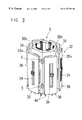
- FIG. 3 is a perspective view showing an embodiment of a stator of the motor shown in FIG. 1;
- FIG. 4 is a perspective view showing an embodiment of a stator yoke of the stator shown in FIG. 3;
- FIG. 5 is a perspective view showing a salient pole and a bobbin of the stator shown in FIG. 3;
- FIG. 6 is a view showing an embodiment of a joint portion of the stator yokes
- FIG. 7 is a view showing the stator yokes having the joint portion shown in FIG. 6;
- FIG. 8 is a view showing another embodiment of a joint portion of the stator yokes
- FIG. 9 a view showing further embodiment of a joint portion of the stator yokes.
- FIG. 10 is a view showing another embodiment of a motor as an example of a rotary electric machine according to the present invention.
- FIG. 1 shows a longitudinal section of a motor 2
- FIG. 2 shows a cross section of the motor 2
- the motor 2 is a 3-phase inner rotor type brushless DC motor having six salient poles and eight rotor field poles.
- the motor 2 comprises a case 4 , a stator 6 secured inside the case 4 , and a rotor 10 built into one piece with a rotary shaft 8 .
- the case 4 is made of metal, has an approximately cylindrical shape, and is provided with flanges 12 and 13 on both ends thereof.
- the flanges 12 and 13 are provided with bearings 20 and 21 . These bearings 20 and 21 rotatably support the rotary shaft 8 .
- the rotor 10 comprises the rotary shaft 8 , a rotor magnet with eight rotor field poles, and a sleeve, and is rotatably supported by the bearings 20 and 21 as mentioned above. Furthermore, the rotor 10 is provided with a spring holder 25 and a spring 23 , whereby the rotor 10 is adequately positioned in the axial direction thereof, and the pre-load onto the bearing 20 is adequately set.
- stator 6 comprises six stator yokes 32 and is secured radially inside the case 4 .
- a stator yoke 32 is shown in FIG. 4, wherein each stator yoke 32 comprises a salient pole 34 , a bobbin 36 for supporting the salient pole 34 , and a magnet wire 38 wound around the bobbin 36 .
- the salient pole 34 comprises nine pieces of electromagnetic steel plates, each having a thickness of 0.35 mm, punched into a shape of a letter T and laminated in parallel to the shaft.
- the narrowly formed portion of the salient pole 34 of T shape is inserted into a rectangular hole 37 of the bobbin 36 , while the elongated portion is so arranged as to project slightly from the bobbin 36 toward the rotary shaft 8 .
- the salient pole 34 may be laminated in the axial direction so as to be inserted into the rectangular hole 37 .
- the bobbin 36 which is made of resin, has collars 39 a and 39 b and a rectangular hole 37 , and is provided with a magnet wire 38 wound around the outer circumference of the rectangular hole 37 .
- the bobbin 36 is provided on the lower end thereof with terminals 40 in which the wound magnetic wire 38 is tied up at the end thereof.
- the magnet wire 38 is tied up at the terminals 40 and then soldered.
- the collar 39 b of the bobbin 36 is provided with notches 3 along the direction of insertion of the salient pole 34 .
- two notches 3 are provided on the upper and lower portions on each edge of the bobbin 36 , respectively in FIG. 3 .
- Combination of two bobbins 36 shown in FIG. 3 provides a through-hole 5 of the collar 39 b.
- stator yokes 32 when six stator yokes 32 are arranged as shown in FIG. 3, the salient poles 34 of the coil will face the rotor 10 via a small air gap, if the rotor 10 is inserted, and through-holes 5 will be provided at two portions, the upper and lower portions, on each assembled portion.
- the stator thus fabricated is arranged on the inner face of the case 4 of the motor 2 and secured there to with resin 58 .
- Mold resin is injected inside the case 4 of the motor 2 after the stator 6 has been arranged at the predetermined position. As shown in FIG. 2, the resin 58 is filled in between the stator 6 and the case 4 , leaving a space at the center for inserting the rotor 10 . The resin 58 is also filled in between the stator yokes 32 and towards the side of the rotor 10 through the through-holes 5 .
- the terminal 40 in which the magnet wire 38 is tied up is connected to a printed circuit board 50 on which electric circuits and electronic parts are mounted.
- the printed circuit board 50 is arranged in an electrically insulated condition on an end of the case 4 approximately in parallel to the flange 13 .
- the printed circuit board 50 includes hall sensors 52 (three in this arrangement) for detecting rotor field poles of the rotor 10 as well as electric circuits, and is connected to a connector 53 for external connection use. With this arrangement information on the position of the rotor 10 in provided via the connector 53 and the rotor 10 in driven by exciting each phase in accordance with such position information from the hall sensors 52 .
- a pin holder 57 made of resin is provided for protection of the connector 53 .
- the edge portions of the bobbins 36 of the stator yokes 32 engage with each other to form through-holes 5 penetrating from the front surface to the rear surface by combination of the bobbins.
- Such arrangement provides accurate coupling of the stator yokes 32 .
- the resin 58 injected after the stator yokes 32 have been accommodated in the case 4 will be filled in toward the side of the rotor 10 though the through-holes 5 . This allows complete filling of the resin 58 even at a low injection pressure, and thus allows shortening time of filling of the resin. Additionally secure fixing of the stator yokes 32 can be attained.
- Through-holes 5 may be provided not on the edges of the bobbin 36 , but may be formed through the collar 39 b itself.
- the bobbin 36 has a projection and a depression on both edge portions of the collar 39 thereof along a longitudinal direction thereof in a mirror image relationship. As shown in FIG. 6, when two bobbins 36 are brought into engagement with each other, the projection and depression of one bobbin 36 engages those of the other bobbin 36 to secured with each other.
- bobbins 36 can be easily handled before the stator 6 is accommodated in the case 4 and can be secured when accommodated in the case 4 , and, moreover, will never cause dislocation to occur when the resin 58 is injected. Furthermore, as the through-holes 5 are formed between the stator yokes 32 connected, if the resin 58 is injected after the stator 6 has been accommodated in the case 4 , then the resin 58 will penetrate through the through-holes 5 to one side and the other side of the bobbins 36 , whereby the stator 6 can be secured to the case 4 .
- the collar 39 b of a first bobbin 36 may be provided with a pin 41
- the collar 39 b of another bobbin 36 to be coupled to the first bobbin may be provided with a hole 43 which can fit the pin 41 , so that these two bobbins are coupled.
- a slot 45 may be adopted for coupling.
- FIG. 10 shows an outer rotor type rotary electric machine having the rotor 10 arranged on the outer circumference.
- the contact portions of a stator 6 arranged at the center are formed so as to secure surface contact with each other, thereby providing positive securing of the contact portions of the stator 6 .
- the collar 39 ′ of the bobbin 36 ′ may be provided with through-holes for allowing resin to pass through or a shape for engaging each other.
- stator structure of the rotary electric machine according to the present invention and the rotary electric machine are not limited to only a motor.
- the salient pole 34 may not be laminated in parallel to the axial direction of the rotary shaft 8 but may be laminated sequentially in the axial direction in the conventional manner.
- the contact portions of the stator yokes are contacted directly with each other so that handling and assembly of the stator will be easy, and secure fixing in the case will be expected.
- through-holes are formed at the stator yokes, so that when resin is filled in between the stator and the case, there will be easy flow of resin through the through-holes to one side and the other side of the collar thereby providing secure fixing of the stator by means of the resin.
- stator yokes is provided on the contact portion with an engagement portion to allow stators to engage each other, whereby a brushless DC motor can be provided allows easy handling in assembly and no dislocation due to the injection of resin, and has a long life and high reliability.
Abstract
Description
Claims (14)
Applications Claiming Priority (2)
| Application Number | Priority Date | Filing Date | Title |
|---|---|---|---|
| JP10-235507 | 1998-08-21 | ||
| JP23550798A JP3421251B2 (en) | 1998-08-21 | 1998-08-21 | Rotating electric machine and its bobbin |
Publications (1)
| Publication Number | Publication Date |
|---|---|
| US6177751B1 true US6177751B1 (en) | 2001-01-23 |
Family
ID=16987035
Family Applications (1)
| Application Number | Title | Priority Date | Filing Date |
|---|---|---|---|
| US09/377,787 Expired - Fee Related US6177751B1 (en) | 1998-08-21 | 1999-08-20 | Rotary electric machine and bobbin thereof |
Country Status (2)
| Country | Link |
|---|---|
| US (1) | US6177751B1 (en) |
| JP (1) | JP3421251B2 (en) |
Cited By (58)
| Publication number | Priority date | Publication date | Assignee | Title |
|---|---|---|---|---|
| US6411006B2 (en) * | 2000-02-24 | 2002-06-25 | Minebera Co., Ltd. | Electric rotary machine |
| US20020084716A1 (en) * | 2001-01-04 | 2002-07-04 | Harter Bernard G. | End cap assembly for a switched reluctance electric machine |
| US20020093269A1 (en) * | 2001-01-16 | 2002-07-18 | Harter Bernard G. | Slot area undercut for segmented stators |
| US20020125782A1 (en) * | 2001-01-04 | 2002-09-12 | Peachee C. T. | Segmented stator switched reluctance machine |
| US20020130577A1 (en) * | 2001-01-15 | 2002-09-19 | Minebea Co., Ltd. | DC motor |
| US20020135255A1 (en) * | 2001-03-26 | 2002-09-26 | Willliams Donald J. | Fan assembly including a segmented stator switched reluctance fan motor |
| US20020135254A1 (en) * | 2001-03-26 | 2002-09-26 | Peachee C. Theodore | Sensorless switched reluctance electric machine with segmented stator |
| US6555942B1 (en) * | 2002-05-10 | 2003-04-29 | Chun-Pu Hsu | Assembly type stator structure having flat wire wound coils |
| WO2003041244A1 (en) * | 2001-11-08 | 2003-05-15 | Matsushita Electric Industrial Co., Ltd. | Motor |
| US6580193B2 (en) * | 2000-03-31 | 2003-06-17 | Asmo Co., Ltd. | Rotary electric machine and manufacturing method therefor |
| US6584813B2 (en) | 2001-03-26 | 2003-07-01 | Emerson Electric Co. | Washing machine including a segmented stator switched reluctance motor |
| US20030141780A1 (en) * | 2002-01-31 | 2003-07-31 | Minebea Co., Ltd. | Electric rotary machine with armature of discrete salient pole structure |
| EP1339156A2 (en) * | 2002-02-25 | 2003-08-27 | Minebea Co., Ltd. | Electric rotary machine having bobbins with thin-walled extensions of flange |
| US20030160523A1 (en) * | 2002-02-27 | 2003-08-28 | Minebea Co., Ltd. | Electric rotary machine with stator armature including barrier walls |
| US6664701B1 (en) | 2002-06-13 | 2003-12-16 | Black & Decker Inc. | Brush assembly |
| US20040000837A1 (en) * | 2002-02-27 | 2004-01-01 | Minebea Co., Ltd. | Electric rotary machine |
| US20040007933A1 (en) * | 2002-07-12 | 2004-01-15 | Chun-Pu Hsu | Assembly type stator structure having flat wire wound coils |
| WO2004017488A1 (en) | 2002-08-16 | 2004-02-26 | Yamaha Hatsudoki Kabushiki Kaisha | Rotating electric machine |
| US6713916B1 (en) | 2002-10-31 | 2004-03-30 | Black & Decker Inc. | Electric motor assembly |
| US20040061386A1 (en) * | 2002-09-27 | 2004-04-01 | Hitachi, Ltd. | Resin-molded stator, a method of manufacturing the same, and a rotary machine using the same |
| US20040084981A1 (en) * | 2002-10-31 | 2004-05-06 | Ortt Earl M. | Electric motor end plate with visual alignment indicia |
| US20040084990A1 (en) * | 2002-10-31 | 2004-05-06 | Ortt Earl M. | Electric motor brush assembly |
| US20040104636A1 (en) * | 2001-02-23 | 2004-06-03 | Ortt Earl M. | Stator assembly with an overmolding that secures magnets to a flux ring and the flux ring to a stator housing |
| US20040113504A1 (en) * | 2002-02-22 | 2004-06-17 | Michael Agnes | Field assembly for a motor and method of making same |
| US20040164641A1 (en) * | 2003-02-26 | 2004-08-26 | Fujitsu General Limited | Axial gap electronic motor |
| US20050073213A1 (en) * | 2001-11-29 | 2005-04-07 | Shinya Naito | Axial gap type dynamo-electric machine |
| US6933646B2 (en) * | 2001-08-30 | 2005-08-23 | Yuki Kinoshita | Electric rotating machine and electromagnetic machine and apparatus |
| EP1573755A2 (en) * | 2002-12-20 | 2005-09-14 | Wellington Drive Technologies Limited | Electrodynamic machine |
| US20050212377A1 (en) * | 2004-03-23 | 2005-09-29 | Emerson Electric Co. | End cap for segmented stator |
| US20050218749A1 (en) * | 2004-03-31 | 2005-10-06 | Lg Electronics Inc | Stator of motor, and method for manufacturing the same |
| US20070013256A1 (en) * | 2002-10-31 | 2007-01-18 | Emerson Electric Co. | Segmented Stator with Improved Handling and Winding Characteristics |
| US20070114877A1 (en) * | 2004-03-23 | 2007-05-24 | Weirong Wang | End cap for interconnecting winding coils of segmented stator to reduce phase-on-phase conditions and associated methods |
| US20070145839A1 (en) * | 2004-03-31 | 2007-06-28 | Denso Corporation | Brushless synchronous motor |
| WO2008039081A3 (en) * | 2006-09-25 | 2008-07-24 | Wellington Drive Technologies | Electronic machines with composite poles |
| US20080303362A1 (en) * | 2007-06-08 | 2008-12-11 | Nissan Motor Co., Ltd. | Motor and motor system |
| WO2009016196A1 (en) * | 2007-08-01 | 2009-02-05 | Siemens Aktiengesellschaft | Electrical machine |
| US20090102310A1 (en) * | 2004-02-06 | 2009-04-23 | Daikin Industries, Ltd. | Stator of motor |
| US20090195112A1 (en) * | 2008-01-11 | 2009-08-06 | Chai Ji Dong | Stator for an electric motor |
| US20090243421A1 (en) * | 2007-02-13 | 2009-10-01 | Kabushiki Kaisha Yaskawa Denki | Electric motor stator and permanent magnet-type electric motor using the same |
| US20100156231A1 (en) * | 2008-12-23 | 2010-06-24 | Amotech Co., Ltd. | Slim type stator, slim type motor having the stator and direct drive apparatus for drum-washing machine |
| US20100181863A1 (en) * | 2009-01-16 | 2010-07-22 | Fujitsu General Limited | Electronic motor |
| US20110050020A1 (en) * | 2007-09-04 | 2011-03-03 | Wellington Drive Technologies Limited | Electronic machines with composite poles |
| CN102088218A (en) * | 2009-12-02 | 2011-06-08 | 大众汽车有限公司 | Winding for a motor rotor or stator and the method of manufacturing same |
| US20110198952A1 (en) * | 2010-02-15 | 2011-08-18 | Manabu Nakamura | Brushless dc motor |
| US20110273041A1 (en) * | 2010-05-10 | 2011-11-10 | Huan-Ching Tseng | Electricity-generating device |
| US20120128512A1 (en) * | 2009-08-03 | 2012-05-24 | Atlas Copco Airpower | Turbocompressor system |
| FR2968481A1 (en) * | 2010-12-07 | 2012-06-08 | Francecol Technology | Rotating alternating-current machine e.g. tetra-polar induction motor, has magnetic yoke comprising variable section in axial plane of machine and formed by assembling small unitary elements made of ferromagnetic material |
| US20120261534A1 (en) * | 2011-04-14 | 2012-10-18 | General Electric Corporation | Electrical Machine Component Mounting Apparatus |
| US20120299400A1 (en) * | 2009-05-29 | 2012-11-29 | Brose Fahrzeugteile Gmbh & Co. Kg, Wuerzburg | Stator for an electric motor |
| US8400041B2 (en) | 2010-05-28 | 2013-03-19 | Nidec Motor Corporation | Segmented stator assemblies having end caps |
| US20130278103A1 (en) * | 2010-12-13 | 2013-10-24 | Mark W. McPherson | Stator used in an electrical motor or generator with low loss magnetic material and method of manufacturing a stator |
| US20160020659A1 (en) * | 2013-01-15 | 2016-01-21 | Mikuni Corporation | Electric motor, pump device using electric motor, and stator |
| US20170141627A1 (en) * | 2012-02-08 | 2017-05-18 | Asmo Co., Ltd. | Stator, brushless motor, stator manufacturing method |
| US20170310180A1 (en) * | 2016-04-20 | 2017-10-26 | Hyundai Motor Company | Driving motor for environmentally friendly vehicles |
| CN107919747A (en) * | 2017-12-19 | 2018-04-17 | 珠海格力节能环保制冷技术研究中心有限公司 | Motor block stator structure and motor stator and motor |
| US9985488B2 (en) | 2011-07-22 | 2018-05-29 | RWXT Nuclear Operations Group, Inc. | Environmentally robust electromagnets and electric motors employing same for use in nuclear reactors |
| US20180166936A1 (en) * | 2016-12-13 | 2018-06-14 | Hyundai Motor Company | Rotor structure of wrsm motor |
| CN109997294A (en) * | 2016-11-28 | 2019-07-09 | 松下知识产权经营株式会社 | Motor |
Families Citing this family (4)
| Publication number | Priority date | Publication date | Assignee | Title |
|---|---|---|---|---|
| KR101134969B1 (en) | 2009-11-19 | 2012-04-09 | 현대자동차주식회사 | Method for manufacturing stator for electric water pump |
| KR101134970B1 (en) | 2009-11-19 | 2012-04-09 | 현대자동차주식회사 | Electric water pump |
| JP5594308B2 (en) * | 2012-03-08 | 2014-09-24 | 株式会社安川電機 | Linear motor armature, linear motor, and armature manufacturing method |
| JP6932546B2 (en) * | 2017-05-19 | 2021-09-08 | エドワーズ株式会社 | A vacuum pump, a magnetic bearing device used in the vacuum pump, and an annular electromagnet. |
Citations (4)
| Publication number | Priority date | Publication date | Assignee | Title |
|---|---|---|---|---|
| US2655613A (en) * | 1952-01-24 | 1953-10-13 | Allis Louis Co | Rotor for dynamoelectric machines |
| US2691113A (en) * | 1952-08-12 | 1954-10-05 | Gen Electric | Dynamoelectric machine rotor |
| US2870357A (en) * | 1955-11-30 | 1959-01-20 | Allis Chalmers Mfg Co | Dynamoelectric machine |
| US4795933A (en) * | 1982-08-06 | 1989-01-03 | Hitachi, Ltd. | Salient-pole rotary electric machine |
-
1998
- 1998-08-21 JP JP23550798A patent/JP3421251B2/en not_active Expired - Fee Related
-
1999
- 1999-08-20 US US09/377,787 patent/US6177751B1/en not_active Expired - Fee Related
Patent Citations (4)
| Publication number | Priority date | Publication date | Assignee | Title |
|---|---|---|---|---|
| US2655613A (en) * | 1952-01-24 | 1953-10-13 | Allis Louis Co | Rotor for dynamoelectric machines |
| US2691113A (en) * | 1952-08-12 | 1954-10-05 | Gen Electric | Dynamoelectric machine rotor |
| US2870357A (en) * | 1955-11-30 | 1959-01-20 | Allis Chalmers Mfg Co | Dynamoelectric machine |
| US4795933A (en) * | 1982-08-06 | 1989-01-03 | Hitachi, Ltd. | Salient-pole rotary electric machine |
Cited By (127)
| Publication number | Priority date | Publication date | Assignee | Title |
|---|---|---|---|---|
| US6411006B2 (en) * | 2000-02-24 | 2002-06-25 | Minebera Co., Ltd. | Electric rotary machine |
| US6580193B2 (en) * | 2000-03-31 | 2003-06-17 | Asmo Co., Ltd. | Rotary electric machine and manufacturing method therefor |
| US20020084716A1 (en) * | 2001-01-04 | 2002-07-04 | Harter Bernard G. | End cap assembly for a switched reluctance electric machine |
| US20020125782A1 (en) * | 2001-01-04 | 2002-09-12 | Peachee C. T. | Segmented stator switched reluctance machine |
| US7012350B2 (en) | 2001-01-04 | 2006-03-14 | Emerson Electric Co. | Segmented stator switched reluctance machine |
| US6744166B2 (en) * | 2001-01-04 | 2004-06-01 | Emerson Electric Co. | End cap assembly for a switched reluctance electric machine |
| US20020130577A1 (en) * | 2001-01-15 | 2002-09-19 | Minebea Co., Ltd. | DC motor |
| US20020093269A1 (en) * | 2001-01-16 | 2002-07-18 | Harter Bernard G. | Slot area undercut for segmented stators |
| US6903475B2 (en) | 2001-02-23 | 2005-06-07 | Black & Decker Inc. | Stator assembly with an overmolding that secures magnets to a flux ring and the flux ring to a stator housing |
| US6983529B2 (en) | 2001-02-23 | 2006-01-10 | Black & Decker Inc. | Stator assembly with an overmolding that secures magnets to a flux ring and the flux ring to a stator housing |
| US20040104636A1 (en) * | 2001-02-23 | 2004-06-03 | Ortt Earl M. | Stator assembly with an overmolding that secures magnets to a flux ring and the flux ring to a stator housing |
| US20050194854A1 (en) * | 2001-02-23 | 2005-09-08 | Michael Agnes | Field assembly for a motor and method of making same |
| US20050189831A1 (en) * | 2001-02-23 | 2005-09-01 | Ortt Earl M. | Stator assembly with an overmolding that secures magnets to a flux ring and the flux ring to a stator housing |
| US7088024B2 (en) | 2001-02-23 | 2006-08-08 | Black & Decker Inc. | Field assembly for a motor and method of making same |
| US20050188528A1 (en) * | 2001-02-23 | 2005-09-01 | Ortt Earl M. | Stator assembly with an overmolding that secures magnets to a flux ring and the flux ring to a stator housing |
| US7091642B2 (en) | 2001-02-23 | 2006-08-15 | Black & Decker Inc. | Field assembly for a motor and method of making same |
| US20050184610A1 (en) * | 2001-02-23 | 2005-08-25 | Michael Agnes | Field assembly for a motor and method of making same |
| US7119469B2 (en) | 2001-02-23 | 2006-10-10 | Black & Decker Inc. | Stator assembly with an overmolding that secures magnets to a flux ring and the flux ring to a stator housing |
| US6700284B2 (en) | 2001-03-26 | 2004-03-02 | Emerson Electric Co. | Fan assembly including a segmented stator switched reluctance fan motor |
| US6897591B2 (en) | 2001-03-26 | 2005-05-24 | Emerson Electric Co. | Sensorless switched reluctance electric machine with segmented stator |
| US20020135254A1 (en) * | 2001-03-26 | 2002-09-26 | Peachee C. Theodore | Sensorless switched reluctance electric machine with segmented stator |
| US6584813B2 (en) | 2001-03-26 | 2003-07-01 | Emerson Electric Co. | Washing machine including a segmented stator switched reluctance motor |
| US20020135255A1 (en) * | 2001-03-26 | 2002-09-26 | Willliams Donald J. | Fan assembly including a segmented stator switched reluctance fan motor |
| US6933646B2 (en) * | 2001-08-30 | 2005-08-23 | Yuki Kinoshita | Electric rotating machine and electromagnetic machine and apparatus |
| WO2003041244A1 (en) * | 2001-11-08 | 2003-05-15 | Matsushita Electric Industrial Co., Ltd. | Motor |
| US7218026B2 (en) | 2001-11-08 | 2007-05-15 | Matsushita Electric Industrial Co., Ltd. | Motor |
| US20050035680A1 (en) * | 2001-11-08 | 2005-02-17 | Hiroshi Murakami | Motor |
| US7173357B2 (en) * | 2001-11-29 | 2007-02-06 | Yamaha Hatsudoki Kabushiki Kaisha | Axial gap type dynamo-electric machine |
| US20050073213A1 (en) * | 2001-11-29 | 2005-04-07 | Shinya Naito | Axial gap type dynamo-electric machine |
| US6717319B2 (en) * | 2002-01-31 | 2004-04-06 | Minebea Co., Ltd. | Electric rotary machine with armature of discrete salient pole structure |
| US20030141780A1 (en) * | 2002-01-31 | 2003-07-31 | Minebea Co., Ltd. | Electric rotary machine with armature of discrete salient pole structure |
| US20040113504A1 (en) * | 2002-02-22 | 2004-06-17 | Michael Agnes | Field assembly for a motor and method of making same |
| US7038343B2 (en) | 2002-02-22 | 2006-05-02 | Black & Decker Inc. | Field assembly for a motor and method of making same |
| EP1339156A3 (en) * | 2002-02-25 | 2006-03-22 | Minebea Co., Ltd. | Electric rotary machine having bobbins with thin-walled extensions of flange |
| EP1339156A2 (en) * | 2002-02-25 | 2003-08-27 | Minebea Co., Ltd. | Electric rotary machine having bobbins with thin-walled extensions of flange |
| US20040000837A1 (en) * | 2002-02-27 | 2004-01-01 | Minebea Co., Ltd. | Electric rotary machine |
| EP1341289A1 (en) * | 2002-02-27 | 2003-09-03 | Minebea Co., Ltd. | Overmold stator including resin injection ports, barrier walls and terminals |
| US6822356B2 (en) | 2002-02-27 | 2004-11-23 | Minebea Co., Ltd. | Electric rotary machine with stator armature including barrier walls |
| US6833649B2 (en) * | 2002-02-27 | 2004-12-21 | Minebea Co., Ltd. | Electric rotary machine |
| US20030160523A1 (en) * | 2002-02-27 | 2003-08-28 | Minebea Co., Ltd. | Electric rotary machine with stator armature including barrier walls |
| US6555942B1 (en) * | 2002-05-10 | 2003-04-29 | Chun-Pu Hsu | Assembly type stator structure having flat wire wound coils |
| US7059038B2 (en) | 2002-06-13 | 2006-06-13 | Black & Decker Inc. | Brush assembly |
| US6664701B1 (en) | 2002-06-13 | 2003-12-16 | Black & Decker Inc. | Brush assembly |
| US20030230951A1 (en) * | 2002-06-13 | 2003-12-18 | Ortt Earl M. | Brush assembly |
| US20040004409A1 (en) * | 2002-06-13 | 2004-01-08 | Ortt Earl M. | Brush assembly |
| US20040007933A1 (en) * | 2002-07-12 | 2004-01-15 | Chun-Pu Hsu | Assembly type stator structure having flat wire wound coils |
| EP1536542A4 (en) * | 2002-08-16 | 2007-05-09 | Yamaha Motor Co Ltd | Rotating electric machine |
| WO2004017488A1 (en) | 2002-08-16 | 2004-02-26 | Yamaha Hatsudoki Kabushiki Kaisha | Rotating electric machine |
| EP1536542A1 (en) * | 2002-08-16 | 2005-06-01 | Yamaha Hatsudoki Kabushiki Kaisha | Rotating electric machine |
| US20040061386A1 (en) * | 2002-09-27 | 2004-04-01 | Hitachi, Ltd. | Resin-molded stator, a method of manufacturing the same, and a rotary machine using the same |
| US7067943B2 (en) * | 2002-09-27 | 2006-06-27 | Hitachi, Ltd. | Resin-molded stator, a method of manufacturing the same, and a rotary machine using the same |
| US20050285456A1 (en) * | 2002-09-27 | 2005-12-29 | Hitachi, Ltd. | Method of manufacturing a resin-molded stator |
| US7147929B2 (en) | 2002-09-27 | 2006-12-12 | Hitachi, Ltd. | Method of manufacturing a resin-molded stator |
| US7126242B2 (en) | 2002-10-31 | 2006-10-24 | Black & Decker Inc. | Electric motor assembly |
| US20080129142A1 (en) * | 2002-10-31 | 2008-06-05 | Emerson Electric Co. | Segmented Stator with Improved Handling and Winding Characteristics |
| US6713916B1 (en) | 2002-10-31 | 2004-03-30 | Black & Decker Inc. | Electric motor assembly |
| US7471025B2 (en) | 2002-10-31 | 2008-12-30 | Emerson Electric Co. | Segmented stator with improved handling and winding characteristics |
| US20040084981A1 (en) * | 2002-10-31 | 2004-05-06 | Ortt Earl M. | Electric motor end plate with visual alignment indicia |
| US20050191888A1 (en) * | 2002-10-31 | 2005-09-01 | Ortt Earl M. | Electric motor brush assembly |
| US20050184608A1 (en) * | 2002-10-31 | 2005-08-25 | Williams Robert B. | Electric motor assembly |
| US6858957B2 (en) | 2002-10-31 | 2005-02-22 | Black & Decker Inc. | Electric motor end plate with visual alignment indicia |
| US6798109B2 (en) | 2002-10-31 | 2004-09-28 | Black & Decker Inc. | Electric motor brush assembly |
| US7135796B2 (en) | 2002-10-31 | 2006-11-14 | Black & Decker Inc. | Electric motor brush assembly |
| US7345397B2 (en) * | 2002-10-31 | 2008-03-18 | Emerson Electric Co. | Segmented stator with improved handling and winding characteristics |
| US20070013256A1 (en) * | 2002-10-31 | 2007-01-18 | Emerson Electric Co. | Segmented Stator with Improved Handling and Winding Characteristics |
| US20040084990A1 (en) * | 2002-10-31 | 2004-05-06 | Ortt Earl M. | Electric motor brush assembly |
| EP1573755A2 (en) * | 2002-12-20 | 2005-09-14 | Wellington Drive Technologies Limited | Electrodynamic machine |
| EP1573755A4 (en) * | 2002-12-20 | 2009-01-21 | Wellington Drive Technologies | Electrodynamic machine |
| US20040164641A1 (en) * | 2003-02-26 | 2004-08-26 | Fujitsu General Limited | Axial gap electronic motor |
| US7221073B2 (en) * | 2003-02-26 | 2007-05-22 | Fujitsu General Limited | Axial gap electronic motor |
| US20090102310A1 (en) * | 2004-02-06 | 2009-04-23 | Daikin Industries, Ltd. | Stator of motor |
| US7944109B2 (en) * | 2004-02-06 | 2011-05-17 | Daikin Industries, Ltd. | Stator of motor having an insulator with lead out guide portions |
| US7382075B2 (en) | 2004-03-23 | 2008-06-03 | Emerson Electric Co. | End cap for segmented stator |
| US7578047B2 (en) | 2004-03-23 | 2009-08-25 | Emerson Electric Co. | Methods of stitching interconnecting wires on a stator to reduce phase-on-phase conditions |
| US20070114877A1 (en) * | 2004-03-23 | 2007-05-24 | Weirong Wang | End cap for interconnecting winding coils of segmented stator to reduce phase-on-phase conditions and associated methods |
| US7414347B2 (en) * | 2004-03-23 | 2008-08-19 | Emerson Electric Co. | End cap for segmented stator |
| US20080296996A1 (en) * | 2004-03-23 | 2008-12-04 | Emerson Electric Co. | End Cap For Segmented Stator |
| US20060028092A1 (en) * | 2004-03-23 | 2006-02-09 | Weirong Wang | End cap for segmented stator |
| US20050212377A1 (en) * | 2004-03-23 | 2005-09-29 | Emerson Electric Co. | End cap for segmented stator |
| US7586231B2 (en) | 2004-03-23 | 2009-09-08 | Emerson Electric Co. | End cap for segmented stator |
| US20050218749A1 (en) * | 2004-03-31 | 2005-10-06 | Lg Electronics Inc | Stator of motor, and method for manufacturing the same |
| US7253547B2 (en) * | 2004-03-31 | 2007-08-07 | Lg Electronics Inc. | Stator of motor, and method for manufacturing the same |
| US7501730B2 (en) * | 2004-03-31 | 2009-03-10 | Denso Corporation | Brushless synchronous motor |
| US20070145839A1 (en) * | 2004-03-31 | 2007-06-28 | Denso Corporation | Brushless synchronous motor |
| WO2008039081A3 (en) * | 2006-09-25 | 2008-07-24 | Wellington Drive Technologies | Electronic machines with composite poles |
| US7830061B2 (en) * | 2007-02-13 | 2010-11-09 | Kabushiki Kaisha Yaskawa Denki | Electric motor stator and permanent magnet-type electric motor using the same |
| US20090243421A1 (en) * | 2007-02-13 | 2009-10-01 | Kabushiki Kaisha Yaskawa Denki | Electric motor stator and permanent magnet-type electric motor using the same |
| US8049383B2 (en) * | 2007-06-08 | 2011-11-01 | Nissan Motor Co., Ltd. | Integrated capacitor-type stator |
| US20080303362A1 (en) * | 2007-06-08 | 2008-12-11 | Nissan Motor Co., Ltd. | Motor and motor system |
| WO2009016196A1 (en) * | 2007-08-01 | 2009-02-05 | Siemens Aktiengesellschaft | Electrical machine |
| US20110050020A1 (en) * | 2007-09-04 | 2011-03-03 | Wellington Drive Technologies Limited | Electronic machines with composite poles |
| US8294326B2 (en) * | 2008-01-11 | 2012-10-23 | Johnson Electric S.A. | Stator for an electric motor |
| US20090195112A1 (en) * | 2008-01-11 | 2009-08-06 | Chai Ji Dong | Stator for an electric motor |
| US20100156231A1 (en) * | 2008-12-23 | 2010-06-24 | Amotech Co., Ltd. | Slim type stator, slim type motor having the stator and direct drive apparatus for drum-washing machine |
| US7965012B2 (en) * | 2009-01-16 | 2011-06-21 | Fujitsu General Limited | Electronic motor |
| US20100181863A1 (en) * | 2009-01-16 | 2010-07-22 | Fujitsu General Limited | Electronic motor |
| US9413202B2 (en) * | 2009-05-29 | 2016-08-09 | Brose Fahrzeugteile Gmbh & Co. Kg, Wuerzburg | Stator for an electric motor |
| US20120299400A1 (en) * | 2009-05-29 | 2012-11-29 | Brose Fahrzeugteile Gmbh & Co. Kg, Wuerzburg | Stator for an electric motor |
| US9470238B2 (en) * | 2009-08-03 | 2016-10-18 | Atlas Copco Airpower, Naamloze Vennootschap | Electric motor having segmented stator windings |
| US20120128512A1 (en) * | 2009-08-03 | 2012-05-24 | Atlas Copco Airpower | Turbocompressor system |
| CN102575682A (en) * | 2009-08-03 | 2012-07-11 | 阿特拉斯·科普柯空气动力股份有限公司 | Turbocompressor system |
| CN102088218A (en) * | 2009-12-02 | 2011-06-08 | 大众汽车有限公司 | Winding for a motor rotor or stator and the method of manufacturing same |
| US20110198952A1 (en) * | 2010-02-15 | 2011-08-18 | Manabu Nakamura | Brushless dc motor |
| US20110273041A1 (en) * | 2010-05-10 | 2011-11-10 | Huan-Ching Tseng | Electricity-generating device |
| US8400041B2 (en) | 2010-05-28 | 2013-03-19 | Nidec Motor Corporation | Segmented stator assemblies having end caps |
| FR2968481A1 (en) * | 2010-12-07 | 2012-06-08 | Francecol Technology | Rotating alternating-current machine e.g. tetra-polar induction motor, has magnetic yoke comprising variable section in axial plane of machine and formed by assembling small unitary elements made of ferromagnetic material |
| US9762095B2 (en) * | 2010-12-13 | 2017-09-12 | Radam Motors, Llc | Stator used in an electrical motor or generator with low loss magnetic material and method of manufacturing a stator |
| US20130278103A1 (en) * | 2010-12-13 | 2013-10-24 | Mark W. McPherson | Stator used in an electrical motor or generator with low loss magnetic material and method of manufacturing a stator |
| US20120261534A1 (en) * | 2011-04-14 | 2012-10-18 | General Electric Corporation | Electrical Machine Component Mounting Apparatus |
| US10770942B2 (en) | 2011-07-22 | 2020-09-08 | Bwxt Nuclear Operations Group, Inc. | Environmentally robust electromagnets and electric motors employing same for use in nuclear reactors |
| US9985488B2 (en) | 2011-07-22 | 2018-05-29 | RWXT Nuclear Operations Group, Inc. | Environmentally robust electromagnets and electric motors employing same for use in nuclear reactors |
| US20170141627A1 (en) * | 2012-02-08 | 2017-05-18 | Asmo Co., Ltd. | Stator, brushless motor, stator manufacturing method |
| US10491057B2 (en) * | 2012-02-08 | 2019-11-26 | Denso Corporation | Stator, brushless motor, stator manufacturing method |
| US10305341B2 (en) * | 2013-01-15 | 2019-05-28 | Mikuni Corporation | Electric motor, pump device using electric motor, and stator |
| US20160020659A1 (en) * | 2013-01-15 | 2016-01-21 | Mikuni Corporation | Electric motor, pump device using electric motor, and stator |
| US10411541B2 (en) * | 2016-04-20 | 2019-09-10 | Hyundai Motor Company | Driving motor for environmentally friendly vehicles |
| US20170310180A1 (en) * | 2016-04-20 | 2017-10-26 | Hyundai Motor Company | Driving motor for environmentally friendly vehicles |
| CN109997294A (en) * | 2016-11-28 | 2019-07-09 | 松下知识产权经营株式会社 | Motor |
| EP3547506A4 (en) * | 2016-11-28 | 2019-11-20 | Panasonic Intellectual Property Management Co., Ltd. | Motor |
| EP3734806A1 (en) * | 2016-11-28 | 2020-11-04 | Panasonic Intellectual Property Management Co., Ltd. | Motor |
| EP3734805A1 (en) * | 2016-11-28 | 2020-11-04 | Panasonic Intellectual Property Management Co., Ltd. | Motor |
| CN109997294B (en) * | 2016-11-28 | 2021-09-28 | 松下知识产权经营株式会社 | Motor |
| CN108616176A (en) * | 2016-12-13 | 2018-10-02 | 现代自动车株式会社 | The rotor structure of WRSM motor |
| US10476331B2 (en) * | 2016-12-13 | 2019-11-12 | Hyundai Motor Company | Rotor structure of WRSM motor |
| US20180166936A1 (en) * | 2016-12-13 | 2018-06-14 | Hyundai Motor Company | Rotor structure of wrsm motor |
| CN108616176B (en) * | 2016-12-13 | 2021-02-19 | 现代自动车株式会社 | Rotor structure of wound rotor driving motor |
| CN107919747A (en) * | 2017-12-19 | 2018-04-17 | 珠海格力节能环保制冷技术研究中心有限公司 | Motor block stator structure and motor stator and motor |
Also Published As
| Publication number | Publication date |
|---|---|
| JP2000069703A (en) | 2000-03-03 |
| JP3421251B2 (en) | 2003-06-30 |
Similar Documents
| Publication | Publication Date | Title |
|---|---|---|
| US6177751B1 (en) | Rotary electric machine and bobbin thereof | |
| JP3146492B2 (en) | Brushless DC motor | |
| JP5945726B2 (en) | Brushless motor and manufacturing method thereof | |
| US7545074B2 (en) | Rotor for automotive alternator having improved magnet holder | |
| KR100362808B1 (en) | Resin molded brushless direct current motor and method of manufacturing the same | |
| JP5354889B2 (en) | Brushless motor | |
| EP0289043A1 (en) | Stepping motor | |
| US20040007934A1 (en) | Interconnecting ring and wire guide | |
| US6812611B2 (en) | Permanent magnet type electric rotating machine | |
| EP1345306B1 (en) | Electric rotary machine having positioning ring for securing salient poles in place | |
| US6737782B2 (en) | Electric rotary machine having bobbins with thin-walled extensions of flange | |
| EP1341289B1 (en) | A radial gap type electric rotary machine with overmould stator | |
| JPH04344137A (en) | Stator for motor and manufacture of the stator | |
| US6700262B2 (en) | Rotary electric machine | |
| US20110198952A1 (en) | Brushless dc motor | |
| JP4002451B2 (en) | Rotating electric machine | |
| EP1333557B1 (en) | Electric rotary machine with salient pole armature | |
| JP4743257B2 (en) | Rotor for rotating electrical machine and method for manufacturing the same | |
| CN113541342A (en) | Outer rotor type motor | |
| JPH11215745A (en) | Electric motor and formation of stator core | |
| US4433259A (en) | Electric rotating machine | |
| JPH10336941A (en) | Motor | |
| KR100240410B1 (en) | Assembling method for permanent type motor | |
| JP3741091B2 (en) | DC brushless motor and sealless pump using it | |
| US20230208265A1 (en) | Motor with Bidirectional Terminals |
Legal Events
| Date | Code | Title | Description |
|---|---|---|---|
| AS | Assignment |
Owner name: MINEBEA CO., LTD., JAPAN Free format text: ASSIGNMENT OF ASSIGNORS INTEREST;ASSIGNORS:SUZUKI, YUZURU;FUJITANI, SAKAE;MATSUSHITA, KUNITAKE;AND OTHERS;REEL/FRAME:010190/0805 Effective date: 19990730 |
|
| FPAY | Fee payment |
Year of fee payment: 4 |
|
| FEPP | Fee payment procedure |
Free format text: PAYOR NUMBER ASSIGNED (ORIGINAL EVENT CODE: ASPN); ENTITY STATUS OF PATENT OWNER: LARGE ENTITY |
|
| FPAY | Fee payment |
Year of fee payment: 8 |
|
| REMI | Maintenance fee reminder mailed | ||
| LAPS | Lapse for failure to pay maintenance fees | ||
| STCH | Information on status: patent discontinuation |
Free format text: PATENT EXPIRED DUE TO NONPAYMENT OF MAINTENANCE FEES UNDER 37 CFR 1.362 |
|
| FP | Lapsed due to failure to pay maintenance fee |
Effective date: 20130123 |