US6152396A - Variable-force discharge mechanism for materials loaded on a reel - Google Patents
Variable-force discharge mechanism for materials loaded on a reel Download PDFInfo
- Publication number
- US6152396A US6152396A US09/293,105 US29310599A US6152396A US 6152396 A US6152396 A US 6152396A US 29310599 A US29310599 A US 29310599A US 6152396 A US6152396 A US 6152396A
- Authority
- US
- United States
- Prior art keywords
- force
- reversing wheel
- reel
- resilient assembly
- counter
- Prior art date
- Legal status (The legal status is an assumption and is not a legal conclusion. Google has not performed a legal analysis and makes no representation as to the accuracy of the status listed.)
- Expired - Lifetime
Links
Images
Classifications
-
- B—PERFORMING OPERATIONS; TRANSPORTING
- B65—CONVEYING; PACKING; STORING; HANDLING THIN OR FILAMENTARY MATERIAL
- B65H—HANDLING THIN OR FILAMENTARY MATERIAL, e.g. SHEETS, WEBS, CABLES
- B65H59/00—Adjusting or controlling tension in filamentary material, e.g. for preventing snarling; Applications of tension indicators
- B65H59/38—Adjusting or controlling tension in filamentary material, e.g. for preventing snarling; Applications of tension indicators by regulating speed of driving mechanism of unwinding, paying-out, forwarding, winding, or depositing devices, e.g. automatically in response to variations in tension
-
- B—PERFORMING OPERATIONS; TRANSPORTING
- B65—CONVEYING; PACKING; STORING; HANDLING THIN OR FILAMENTARY MATERIAL
- B65H—HANDLING THIN OR FILAMENTARY MATERIAL, e.g. SHEETS, WEBS, CABLES
- B65H59/00—Adjusting or controlling tension in filamentary material, e.g. for preventing snarling; Applications of tension indicators
- B65H59/10—Adjusting or controlling tension in filamentary material, e.g. for preventing snarling; Applications of tension indicators by devices acting on running material and not associated with supply or take-up devices
- B65H59/36—Floating elements compensating for irregularities in supply or take-up of material
Definitions
- the present invention relates to a variable-force discharge mechanism for materials loaded on a reel, comprising
- the relevant materials to be discharged are especially pipes, rods, wires or cables of metal or plastics, which are discharged from a reel to an external device for effecting a cutting, a bending, a punching, a shaping or the like working process.
- An object of the invention is to provide a discharge mechanism of the above type, wherein the tensile stress fluctuations applied to a material can be largely stabilized without the above-mentioned drawbacks.
- An external device 1 draws a material 5 with a force F from a reel 2.
- the material 5 to be discharged comprises a pipe, a rod, a wire or a cable of metal or plastics.
- the material 5 is processed in the external device 1.
- the process in question could be cutting, bending, punching, shaping or the like. In a typical case, such processes require that the material 5 be drawn intermittently with intermissions between the drawing cycles. Since the material reel 2 can be very heavy indeed, the material 5 would be subjected to major fluctuations of tensile stress unless the material 5 were carried through a resilient assembly for stabilizing tensile stresses.
- the resilient assembly comprises a pneumatic piston-cylinder unit 7 associated with a reversing wheel 6, wherein the gas pressure producing a counter-force is adjustable with a regulating valve 9 which, through the intermediary of a tube 8, sustains a constant pressure in the space of the cylinder 7 next to the piston rod.
- the reversing wheel 6 is able to move over a certain displacement A towards the external device 1 in such a way that a counter-force produced for the force F remains nearly constant.
- the drawing speed fluctuates and the reel 2 has a fluctuating rotational speed
- the material 5 will nevertheless have a tensile stress which remains substantially constant.
- the level of tensile stress is determined on the basis of a gas pressure existing in the cylinder 7.
- the valve 9 can be used for setting various levels of constant pressure in the cylinder 7, which enables the adjustment of a variety of tensile stress levels selected in accordance with any given material 5 to be discharged.
- the resilient assembly 7-9 has an operating range which allows the certain displacement A for the reversing wheel 6.
- a discharge motor 3 is adapted to be controlled by a sensor 10 for the displacement of the reversing wheel 6 in such a way that the reel has discharge rate which increases as the reversing wheel 6 travels towards the material reel 2 and the external device 1, and said discharge rate being reduced as the reversing wheel 6 travels in the opposite direction.
- the displacement sensor can be continuously operating, e.g. a linear potentiometer, or it may operate stepwise by means of several sequential position sensors.
- a signal received from the displacement sensor 10 is used for controlling, through the intermediary of a regulating unit 12, the rotating speed of the motor 3 or the transmission ratio between the motor 3 and the reel 2.
- the cylinder 7 has its piston rod and the displacement sensor has its movable component attached to an element 11, which is movable along with the reversing wheel 6 and which is supported to be linearly reciprocating along slide bars 13. This motion of the reversing wheel 6 occurs as a result of the fluctuations of reversed forces produced by the resilient assembly 7-9 and the traction device 1.
- the reversing wheel 6 must have a sufficient radius in order not to shape the material but merely to deflect or reverse its traveling direction by 180°.
- the arrangement of the invention is capable of bringing the material to the traction device 1 as straight as possible.
- the components are mounted on frame structures, which are not shown and which a skilled person is able to implement in a variety of ways.
- the resilient assembly 7-9 functioning as "a buffer storage" for tensile stress produces an almost permanently constant counter-force over the relatively long displacement A.
- the control of discharge rate effected by means of the displacement sensor 10 makes sure that the resilient assembly always remains within its operating range.
- the resilient assembly may have its pneumatic counter-pressure based on a pressure produced by a fan applying to the linearly movable element.
- the resilient assembly can also be constructed hydraulically by using a flow-throttle regulating valve, which is controlled by means of a pressure sensor monitoring the pressure that produces the counter-force.
Abstract
The invention relates to a variable-force discharge mechanism for materials loaded on a reel. Some material is drawn with an external device (1) from a reel (2) around a reversing wheel (6), said reel being driven or decelerated with a discharge motor (3). In order to reduce the tensile stress fluctuations of a material (5), the reversing wheel (6) is afforded a certain displacement (A), within which a resilient assembly (7-9) produces a counter-force for a traction force (F). The counter-force produced by the resilient assembly is created by a piston-cylinder unit (7), having its gas pressure adjustable by a regulating valve (9) which sustains an adjustable, constant counter-force.
Description
The present invention relates to a variable-force discharge mechanism for materials loaded on a reel, comprising
a material reel
a discharge motor for assisting in unloading the reel
an external device for applying a discharging traction force to a material to be discharged
a reversing wheel between the material reel and the external device, and
a resilient assembly in connection with the reversing wheel for adjusting the discharge force.
This type of prior known mechanisms have employed weights or a spring as a resilient means for adjusting a discharge force. A problem associated with the use of counterweights is a major inertia which, as a result of speed fluctuations, subjects the material to major stress fluctuations. A problem in spring loading is the variation of a counter-force over a long operating range as well as the difficulty of swiftly adjusting the starting level of a counter-force to comply with the change of materials to be discharged.
When applying the invention, the relevant materials to be discharged are especially pipes, rods, wires or cables of metal or plastics, which are discharged from a reel to an external device for effecting a cutting, a bending, a punching, a shaping or the like working process.
An object of the invention is to provide a discharge mechanism of the above type, wherein the tensile stress fluctuations applied to a material can be largely stabilized without the above-mentioned drawbacks.
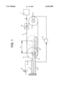
One exemplary embodiment of the invention will now be described in more detail with reference made to the accompanying drawing, which depicts a discharge mechanism of the invention according to one embodiment thereof schemantially in a lateral view.
An external device 1 draws a material 5 with a force F from a reel 2. The material 5 to be discharged comprises a pipe, a rod, a wire or a cable of metal or plastics. The material 5 is processed in the external device 1. The process in question could be cutting, bending, punching, shaping or the like. In a typical case, such processes require that the material 5 be drawn intermittently with intermissions between the drawing cycles. Since the material reel 2 can be very heavy indeed, the material 5 would be subjected to major fluctuations of tensile stress unless the material 5 were carried through a resilient assembly for stabilizing tensile stresses.
As for this invention, the resilient assembly comprises a pneumatic piston-cylinder unit 7 associated with a reversing wheel 6, wherein the gas pressure producing a counter-force is adjustable with a regulating valve 9 which, through the intermediary of a tube 8, sustains a constant pressure in the space of the cylinder 7 next to the piston rod. Thus, the reversing wheel 6 is able to move over a certain displacement A towards the external device 1 in such a way that a counter-force produced for the force F remains nearly constant. While the drawing speed fluctuates and the reel 2 has a fluctuating rotational speed, the material 5 will nevertheless have a tensile stress which remains substantially constant. The level of tensile stress is determined on the basis of a gas pressure existing in the cylinder 7. In addition, the valve 9 can be used for setting various levels of constant pressure in the cylinder 7, which enables the adjustment of a variety of tensile stress levels selected in accordance with any given material 5 to be discharged.
Hence, the resilient assembly 7-9 has an operating range which allows the certain displacement A for the reversing wheel 6. In order to hold the resilient assembly 7-9 within the operating range, a discharge motor 3 is adapted to be controlled by a sensor 10 for the displacement of the reversing wheel 6 in such a way that the reel has discharge rate which increases as the reversing wheel 6 travels towards the material reel 2 and the external device 1, and said discharge rate being reduced as the reversing wheel 6 travels in the opposite direction.
The displacement sensor can be continuously operating, e.g. a linear potentiometer, or it may operate stepwise by means of several sequential position sensors. A signal received from the displacement sensor 10 is used for controlling, through the intermediary of a regulating unit 12, the rotating speed of the motor 3 or the transmission ratio between the motor 3 and the reel 2. In the illustrated case, the cylinder 7 has its piston rod and the displacement sensor has its movable component attached to an element 11, which is movable along with the reversing wheel 6 and which is supported to be linearly reciprocating along slide bars 13. This motion of the reversing wheel 6 occurs as a result of the fluctuations of reversed forces produced by the resilient assembly 7-9 and the traction device 1. What is essential is that this action of the reversing wheel 6 is parallel to the discharging traction force F and the drawing direction of the material 5, the direction of material 5 present between the reversing wheel 6 and the traction device 1 remaining unchanged. Thus, it is possible to use between the reversing wheel 6 and the traction device 1 an alignment unit 14 provided with straightening rollers, having a straightening alignment which is always parallel to the material drawing direction.
Furthermore, the reversing wheel 6 must have a sufficient radius in order not to shape the material but merely to deflect or reverse its traveling direction by 180°.
The arrangement of the invention is capable of bringing the material to the traction device 1 as straight as possible. The components are mounted on frame structures, which are not shown and which a skilled person is able to implement in a variety of ways.
Another important feature in the invention is that the resilient assembly 7-9 functioning as "a buffer storage" for tensile stress produces an almost permanently constant counter-force over the relatively long displacement A. The control of discharge rate effected by means of the displacement sensor 10 makes sure that the resilient assembly always remains within its operating range.
The invention is not limited to the above exemplary embodiment. For example, the resilient assembly may have its pneumatic counter-pressure based on a pressure produced by a fan applying to the linearly movable element. The resilient assembly can also be constructed hydraulically by using a flow-throttle regulating valve, which is controlled by means of a pressure sensor monitoring the pressure that produces the counter-force. Many other modifications of structural design are also conceivable within the scope of the following claims.
Claims (1)
1. A variable-force discharge mechanism for pipe or rod of a metal material loaded on a reel, said mechanism comprising:
a reel (2) for containing metal material in the form of pipe or rod,
a discharge motor (3) for assisting in unloading the reel (2),
an external traction device (1) for applying a discharging traction force (F) to the metal material to be discharged, said external traction device (6) adapted to draw said metal material and to exert said discharging traction force in a predetermined direction,
a reversing wheel (6) between said reel (2) and said external traction device (1), said reversing wheel adapted to travel along slide bars (13),
an alignment unit (14) between said reversing wheel (6) and said external traction device (1), said alignment unit (14) having straightening rollers having straightening alignment which is parallel to said predetermined drawing direction, and
a resilient assembly (7-9) in connection with said reversing wheel (6) for adjustable creating a counter-force produced by said resilient assembly (7-9) in a direction opposite to said predetermined direction of said discharging traction force (F), said counterforce being adapted to be produced by a piston-cylinder unit (7) having a gas pressure that is adjustable by means of a regulating valve (9) sustaining said adjustable counter force, said resilient assembly (7-9) having an operating range which allows a certain displacement (A) for said reversing wheel (6) caused by said discharging traction force in said predetermined direction against said counter-force, said resilient assembly (7-9) producing, when operating within this range, said counter-force determined by said adjustable gas pressure for said discharging traction force (F) and thus reducing the fluctuation of tensile stress applied to the material (5),
a displacement sensor (10) for sensing the displacement of said reversing wheel (6) is adapted to control said discharge motor (3) for holding said resilient assembly (7-9) within said operating range, said displacement sensor (10) adapted to supply a regulating unit (12) of said discharge motor (3) continuously or stepwise with a regulation signal variable as a function of said reversing wheel displacement, said regulation signal increasing the discharge rate of said reel (2) as said reversing wheel (6) is displaced towards said reel (2) and said external traction device (1), wherein as a result of the fluctuation of forces produced by the resilient assembly (7-9) and said external traction device (1), the reversing wheel (6) is adapted to travel along said slide bars (13) linearly back and forth and parallel to said discharging traction force (F) and the drawing action of the material (5) whereby, when the material is moving, the material (5) present between said reversing wheel and said external traction device (1) maintains its direction unchanged.
Applications Claiming Priority (2)
| Application Number | Priority Date | Filing Date | Title |
|---|---|---|---|
| FI980854A FI112464B (en) | 1998-04-17 | 1998-04-17 | Dispensing device with adjustable force for roll-packed materials |
| FI980854 | 1998-04-17 |
Publications (1)
| Publication Number | Publication Date |
|---|---|
| US6152396A true US6152396A (en) | 2000-11-28 |
Family
ID=8551531
Family Applications (1)
| Application Number | Title | Priority Date | Filing Date |
|---|---|---|---|
| US09/293,105 Expired - Lifetime US6152396A (en) | 1998-04-17 | 1999-04-16 | Variable-force discharge mechanism for materials loaded on a reel |
Country Status (8)
| Country | Link |
|---|---|
| US (1) | US6152396A (en) |
| EP (1) | EP0950630B1 (en) |
| JP (1) | JPH11314850A (en) |
| KR (1) | KR19990083144A (en) |
| BR (1) | BR9901826A (en) |
| DE (1) | DE69908480T2 (en) |
| ES (1) | ES2195534T3 (en) |
| FI (1) | FI112464B (en) |
Cited By (6)
| Publication number | Priority date | Publication date | Assignee | Title |
|---|---|---|---|---|
| US20030172531A1 (en) * | 2002-03-14 | 2003-09-18 | Bhagwat Anand Waman | Method of manufacturing flat wire coil springs to improve fatigue life and avoid blue brittleness |
| US20100090051A1 (en) * | 2008-10-10 | 2010-04-15 | Abb Technology Ag | Automated dereeler |
| US10280035B2 (en) * | 2017-04-07 | 2019-05-07 | Dongguan City Qingfeng Electrical Machinery Co., Ltd. | Kind of power paying-off cradle and power paying-off full-automatic stranding cable machine |
| CN114671301A (en) * | 2022-03-17 | 2022-06-28 | 合肥通晟智能装备有限公司 | Extremely low tensile sectional type control system of tow in fiber placement equipment |
| CN114787059A (en) * | 2019-10-21 | 2022-07-22 | 里特机械公司 | Method for driving a mechanical element comprising a yarn catcher on a textile machine, device for moving a yarn on a textile machine and textile machine |
| US11415031B2 (en) | 2017-07-21 | 2022-08-16 | Bosal Emission Control Systems Nv | Method for forming a collar in a muffler housing |
Families Citing this family (6)
| Publication number | Priority date | Publication date | Assignee | Title |
|---|---|---|---|---|
| DE10154823B4 (en) * | 2001-11-08 | 2006-09-14 | Maschinenfabrik Niehoff Gmbh & Co. Kg | Device for rewinding and wrapping thin winding material |
| CN1304262C (en) * | 2004-10-10 | 2007-03-14 | 钱沛良 | Automatic tension controller |
| CN105084109A (en) * | 2015-08-27 | 2015-11-25 | 安庆日月电缆有限公司 | Laying tension adjusting mechanism of aluminum wire drawing machine and laying tension adjusting method of laying tension adjusting mechanism |
| CN105180755A (en) * | 2015-08-27 | 2015-12-23 | 安庆日月电缆有限公司 | Auxiliary tool for drawing machine |
| CN106429621A (en) * | 2016-09-28 | 2017-02-22 | 东莞市联洲知识产权运营管理有限公司 | Variable speed automatic recycling device for scrap edges of window membrane |
| CN110861971B (en) * | 2019-11-28 | 2021-08-27 | 湖南新耒传导材料科技有限公司 | Stranded wire plate rack capable of self-adapting to tension force |
Citations (22)
| Publication number | Priority date | Publication date | Assignee | Title |
|---|---|---|---|---|
| US2681184A (en) * | 1953-04-17 | 1954-06-15 | Lewis C Thomas | Wire tension control |
| CA663442A (en) * | 1963-05-21 | Vischulis George | Floating roller mounting for web tension control systems | |
| US3240058A (en) * | 1963-04-08 | 1966-03-15 | Mount Hope Machinery Ltd | Continuous tension monitor for webfeeding mechanisms |
| GB1048175A (en) * | 1965-07-09 | 1966-11-16 | Plamag Plauener Druckmaschinen | Paper web tension governor |
| US3509595A (en) * | 1964-12-14 | 1970-05-05 | Phillips Petroleum Co | Tension control of running thermoplastic filaments |
| SU642250A1 (en) * | 1976-04-16 | 1979-01-15 | Рыбинское Специальное Конструкторское Бюро Полиграфического Машиностроения | Tension regulator |
| US4151594A (en) * | 1976-02-26 | 1979-04-24 | Bobst-Champlain, Inc. | Web tension control for high-speed web handling equipment |
| US4316587A (en) * | 1979-06-08 | 1982-02-23 | Astin-France Assistance Technique Industrille | Device for regulating the tension of a travelling web |
| US4318513A (en) * | 1979-06-21 | 1982-03-09 | Martinez Manuel T | Tension adjustment system of the paper belt on feeding units of paper manufacturing machines |
| EP0114365A2 (en) * | 1982-12-27 | 1984-08-01 | Sumitomo Electric Industries Limited | Wire or thread tension controlling dancer roller device |
| DE8609191U1 (en) * | 1986-04-05 | 1986-08-07 | HTS-Elektrotechnik GmbH, 5206 Neunkirchen-Seelscheid | Unwinding device for bend-sensitive profile material |
| DE3525022A1 (en) * | 1985-07-11 | 1987-01-22 | Siemens Ag | Central helical spinner for elongate material |
| DE3702702A1 (en) * | 1986-02-27 | 1987-09-03 | Baer Maschf Josef | Control device for the thread tension in winding machines, in particular in fibre lap technology |
| EP0275852A1 (en) * | 1986-12-19 | 1988-07-27 | Nokia-Maillefer Holding S.A. | Method and device for feeding a cable |
| US4838498A (en) * | 1988-02-22 | 1989-06-13 | Rockwell International Corporation | Web tensioning system |
| DE3929897A1 (en) * | 1989-09-08 | 1991-03-14 | Ant Nachrichtentech | Optical fibre guidance - to stranding machine by lifting bracket stopping plate and machine unless fibre is raised off plate |
| US5186409A (en) * | 1989-05-12 | 1993-02-16 | Kabushikigaisha Tokyo Kikai Seisakusho | Tension control device for printing paper |
| WO1997002203A1 (en) * | 1995-07-06 | 1997-01-23 | Nokia-Maillefer Holding S.A. | Method and arrangement in connection with an accumulator of a cable or the like |
| US5632175A (en) * | 1995-10-27 | 1997-05-27 | Green; Paul O. | Rebar fabricating apparatus |
| US5713533A (en) * | 1996-09-09 | 1998-02-03 | Mechanical Tool & Engineering Co. | Stock feed apparatus |
| WO1998027002A1 (en) * | 1996-12-17 | 1998-06-25 | Nextrom Holding S.A. | Arrangement in connection with a spooler |
| US5887816A (en) * | 1997-07-28 | 1999-03-30 | Accra-Wire Controls Inc. | Dereeler for selectively feeding coiled stock into an associated fabricating machine |
-
1998
- 1998-04-17 FI FI980854A patent/FI112464B/en active
-
1999
- 1999-03-30 ES ES99660055T patent/ES2195534T3/en not_active Expired - Lifetime
- 1999-03-30 DE DE69908480T patent/DE69908480T2/en not_active Expired - Lifetime
- 1999-03-30 EP EP99660055A patent/EP0950630B1/en not_active Expired - Lifetime
- 1999-04-07 JP JP11100485A patent/JPH11314850A/en active Pending
- 1999-04-13 KR KR1019990012884A patent/KR19990083144A/en not_active Application Discontinuation
- 1999-04-16 US US09/293,105 patent/US6152396A/en not_active Expired - Lifetime
- 1999-04-16 BR BR9901826-8A patent/BR9901826A/en active Search and Examination
Patent Citations (22)
| Publication number | Priority date | Publication date | Assignee | Title |
|---|---|---|---|---|
| CA663442A (en) * | 1963-05-21 | Vischulis George | Floating roller mounting for web tension control systems | |
| US2681184A (en) * | 1953-04-17 | 1954-06-15 | Lewis C Thomas | Wire tension control |
| US3240058A (en) * | 1963-04-08 | 1966-03-15 | Mount Hope Machinery Ltd | Continuous tension monitor for webfeeding mechanisms |
| US3509595A (en) * | 1964-12-14 | 1970-05-05 | Phillips Petroleum Co | Tension control of running thermoplastic filaments |
| GB1048175A (en) * | 1965-07-09 | 1966-11-16 | Plamag Plauener Druckmaschinen | Paper web tension governor |
| US4151594A (en) * | 1976-02-26 | 1979-04-24 | Bobst-Champlain, Inc. | Web tension control for high-speed web handling equipment |
| SU642250A1 (en) * | 1976-04-16 | 1979-01-15 | Рыбинское Специальное Конструкторское Бюро Полиграфического Машиностроения | Tension regulator |
| US4316587A (en) * | 1979-06-08 | 1982-02-23 | Astin-France Assistance Technique Industrille | Device for regulating the tension of a travelling web |
| US4318513A (en) * | 1979-06-21 | 1982-03-09 | Martinez Manuel T | Tension adjustment system of the paper belt on feeding units of paper manufacturing machines |
| EP0114365A2 (en) * | 1982-12-27 | 1984-08-01 | Sumitomo Electric Industries Limited | Wire or thread tension controlling dancer roller device |
| DE3525022A1 (en) * | 1985-07-11 | 1987-01-22 | Siemens Ag | Central helical spinner for elongate material |
| DE3702702A1 (en) * | 1986-02-27 | 1987-09-03 | Baer Maschf Josef | Control device for the thread tension in winding machines, in particular in fibre lap technology |
| DE8609191U1 (en) * | 1986-04-05 | 1986-08-07 | HTS-Elektrotechnik GmbH, 5206 Neunkirchen-Seelscheid | Unwinding device for bend-sensitive profile material |
| EP0275852A1 (en) * | 1986-12-19 | 1988-07-27 | Nokia-Maillefer Holding S.A. | Method and device for feeding a cable |
| US4838498A (en) * | 1988-02-22 | 1989-06-13 | Rockwell International Corporation | Web tensioning system |
| US5186409A (en) * | 1989-05-12 | 1993-02-16 | Kabushikigaisha Tokyo Kikai Seisakusho | Tension control device for printing paper |
| DE3929897A1 (en) * | 1989-09-08 | 1991-03-14 | Ant Nachrichtentech | Optical fibre guidance - to stranding machine by lifting bracket stopping plate and machine unless fibre is raised off plate |
| WO1997002203A1 (en) * | 1995-07-06 | 1997-01-23 | Nokia-Maillefer Holding S.A. | Method and arrangement in connection with an accumulator of a cable or the like |
| US5632175A (en) * | 1995-10-27 | 1997-05-27 | Green; Paul O. | Rebar fabricating apparatus |
| US5713533A (en) * | 1996-09-09 | 1998-02-03 | Mechanical Tool & Engineering Co. | Stock feed apparatus |
| WO1998027002A1 (en) * | 1996-12-17 | 1998-06-25 | Nextrom Holding S.A. | Arrangement in connection with a spooler |
| US5887816A (en) * | 1997-07-28 | 1999-03-30 | Accra-Wire Controls Inc. | Dereeler for selectively feeding coiled stock into an associated fabricating machine |
Cited By (8)
| Publication number | Priority date | Publication date | Assignee | Title |
|---|---|---|---|---|
| US20030172531A1 (en) * | 2002-03-14 | 2003-09-18 | Bhagwat Anand Waman | Method of manufacturing flat wire coil springs to improve fatigue life and avoid blue brittleness |
| US7055244B2 (en) | 2002-03-14 | 2006-06-06 | Anand Waman Bhagwat | Method of manufacturing flat wire coil springs to improve fatigue life and avoid blue brittleness |
| US20100090051A1 (en) * | 2008-10-10 | 2010-04-15 | Abb Technology Ag | Automated dereeler |
| US8205819B2 (en) * | 2008-10-10 | 2012-06-26 | Abb Technology Ag | Automated dereeler |
| US10280035B2 (en) * | 2017-04-07 | 2019-05-07 | Dongguan City Qingfeng Electrical Machinery Co., Ltd. | Kind of power paying-off cradle and power paying-off full-automatic stranding cable machine |
| US11415031B2 (en) | 2017-07-21 | 2022-08-16 | Bosal Emission Control Systems Nv | Method for forming a collar in a muffler housing |
| CN114787059A (en) * | 2019-10-21 | 2022-07-22 | 里特机械公司 | Method for driving a mechanical element comprising a yarn catcher on a textile machine, device for moving a yarn on a textile machine and textile machine |
| CN114671301A (en) * | 2022-03-17 | 2022-06-28 | 合肥通晟智能装备有限公司 | Extremely low tensile sectional type control system of tow in fiber placement equipment |
Also Published As
| Publication number | Publication date |
|---|---|
| FI112464B (en) | 2003-12-15 |
| JPH11314850A (en) | 1999-11-16 |
| ES2195534T3 (en) | 2003-12-01 |
| DE69908480D1 (en) | 2003-07-10 |
| FI980854A (en) | 1999-10-18 |
| FI980854A0 (en) | 1998-04-17 |
| BR9901826A (en) | 1999-12-14 |
| KR19990083144A (en) | 1999-11-25 |
| EP0950630A1 (en) | 1999-10-20 |
| DE69908480T2 (en) | 2004-04-15 |
| EP0950630B1 (en) | 2003-06-04 |
Similar Documents
| Publication | Publication Date | Title |
|---|---|---|
| US6152396A (en) | Variable-force discharge mechanism for materials loaded on a reel | |
| RU2719038C2 (en) | Passive tensioning system for control of unwinding composite material | |
| US4565081A (en) | Forming machine | |
| US4481768A (en) | Pneumatic control system for machines | |
| EP0633076A1 (en) | Tube bending apparatus and method | |
| AU747820B2 (en) | Grinder pressing device | |
| US5481891A (en) | Tube bending apparatus and method | |
| KR100220346B1 (en) | Device and control method for buffering break-through of press | |
| DE1783132A1 (en) | Continuous casting machine | |
| CN1164817C (en) | Warp knitting machine with at least one guide bar | |
| US3994445A (en) | Compensator for controlling the tension of a wire travelling through a wire-working machine | |
| GB2140871A (en) | Piston and cylinder actuator control | |
| DE10331064A1 (en) | Material strip processing equipment has a sonic horn which meets a stop whose stop face position can be varied to create different processing gaps | |
| US4104899A (en) | Pneumatic buffering system | |
| US3370452A (en) | Mobile forging manipulators | |
| KR900004990A (en) | Tension control device of moving thread | |
| US3457797A (en) | Variable speed drive | |
| EP0086276A1 (en) | Device for maintaining the product of the delivery pressure and delivery rate of an adjustable pump at a constant level | |
| JPS6228329B2 (en) | ||
| US4629105A (en) | Apparatus for driving a taut rigid wire between two grooved wheels | |
| JP7341777B2 (en) | Press device, slide speed control method of press device, and slide speed control program | |
| US4213365A (en) | Press | |
| EP0422775A2 (en) | A window regulator | |
| US2847211A (en) | Web tension controlling device particularly for use in association with printing machines | |
| JPS6158979A (en) | Shape memory alloy actuator |
Legal Events
| Date | Code | Title | Description |
|---|---|---|---|
| AS | Assignment |
Owner name: T-DRILL OY, FINLAND Free format text: ASSIGNMENT OF ASSIGNORS INTEREST;ASSIGNORS:RAPILA, TERO;LEHTO, PERTTI;REEL/FRAME:010109/0424 Effective date: 19990712 |
|
| STCF | Information on status: patent grant |
Free format text: PATENTED CASE |
|
| FPAY | Fee payment |
Year of fee payment: 4 |
|
| FPAY | Fee payment |
Year of fee payment: 8 |
|
| FPAY | Fee payment |
Year of fee payment: 12 |