US6149433A - One-piece impression coping for customized implant restorative systems - Google Patents
One-piece impression coping for customized implant restorative systems Download PDFInfo
- Publication number
- US6149433A US6149433A US09/184,730 US18473098A US6149433A US 6149433 A US6149433 A US 6149433A US 18473098 A US18473098 A US 18473098A US 6149433 A US6149433 A US 6149433A
- Authority
- US
- United States
- Prior art keywords
- fixture
- impression
- mating
- dental
- coping device
- Prior art date
- Legal status (The legal status is an assumption and is not a legal conclusion. Google has not performed a legal analysis and makes no representation as to the accuracy of the status listed.)
- Expired - Lifetime
Links
- 230000010485 coping Effects 0.000 title claims abstract description 92
- 239000007943 implant Substances 0.000 title abstract description 8
- 230000013011 mating Effects 0.000 claims abstract description 47
- 239000004053 dental implant Substances 0.000 claims abstract description 7
- 239000000463 material Substances 0.000 claims description 9
- 230000000295 complement effect Effects 0.000 claims description 3
- 239000004417 polycarbonate Substances 0.000 claims description 3
- 229920000515 polycarbonate Polymers 0.000 claims description 3
- 239000004697 Polyetherimide Substances 0.000 claims description 2
- 229920005669 high impact polystyrene Polymers 0.000 claims description 2
- 239000004797 high-impact polystyrene Substances 0.000 claims description 2
- 229920001601 polyetherimide Polymers 0.000 claims description 2
- 210000004513 dentition Anatomy 0.000 description 17
- 230000036346 tooth eruption Effects 0.000 description 17
- 238000000034 method Methods 0.000 description 8
- 238000005259 measurement Methods 0.000 description 6
- 239000012778 molding material Substances 0.000 description 6
- 238000011179 visual inspection Methods 0.000 description 6
- 230000008569 process Effects 0.000 description 5
- 238000010276 construction Methods 0.000 description 3
- 238000003780 insertion Methods 0.000 description 3
- 230000037431 insertion Effects 0.000 description 3
- 230000007246 mechanism Effects 0.000 description 3
- 210000001519 tissue Anatomy 0.000 description 3
- 230000000007 visual effect Effects 0.000 description 3
- 210000000988 bone and bone Anatomy 0.000 description 2
- 238000005094 computer simulation Methods 0.000 description 2
- KPUWHANPEXNPJT-UHFFFAOYSA-N disiloxane Chemical class [SiH3]O[SiH3] KPUWHANPEXNPJT-UHFFFAOYSA-N 0.000 description 2
- -1 for example Substances 0.000 description 2
- 230000035876 healing Effects 0.000 description 2
- 238000004519 manufacturing process Methods 0.000 description 2
- 239000000758 substrate Substances 0.000 description 2
- 239000004721 Polyphenylene oxide Substances 0.000 description 1
- 239000000853 adhesive Substances 0.000 description 1
- 230000001070 adhesive effect Effects 0.000 description 1
- 210000003484 anatomy Anatomy 0.000 description 1
- 238000004873 anchoring Methods 0.000 description 1
- 239000000919 ceramic Substances 0.000 description 1
- 238000004891 communication Methods 0.000 description 1
- 239000002537 cosmetic Substances 0.000 description 1
- 230000008878 coupling Effects 0.000 description 1
- 238000010168 coupling process Methods 0.000 description 1
- 238000005859 coupling reaction Methods 0.000 description 1
- 238000005553 drilling Methods 0.000 description 1
- 238000001746 injection moulding Methods 0.000 description 1
- 238000000465 moulding Methods 0.000 description 1
- 230000003287 optical effect Effects 0.000 description 1
- 230000035479 physiological effects, processes and functions Effects 0.000 description 1
- 239000004033 plastic Substances 0.000 description 1
- 229920003023 plastic Polymers 0.000 description 1
- 229920000570 polyether Polymers 0.000 description 1
- 229920000642 polymer Polymers 0.000 description 1
- 230000000717 retained effect Effects 0.000 description 1
- 239000007787 solid Substances 0.000 description 1
- 229920002554 vinyl polymer Polymers 0.000 description 1
Images

Classifications
-
- A—HUMAN NECESSITIES
- A61—MEDICAL OR VETERINARY SCIENCE; HYGIENE
- A61C—DENTISTRY; APPARATUS OR METHODS FOR ORAL OR DENTAL HYGIENE
- A61C8/00—Means to be fixed to the jaw-bone for consolidating natural teeth or for fixing dental prostheses thereon; Dental implants; Implanting tools
- A61C8/0001—Impression means for implants, e.g. impression coping
-
- B—PERFORMING OPERATIONS; TRANSPORTING
- B33—ADDITIVE MANUFACTURING TECHNOLOGY
- B33Y—ADDITIVE MANUFACTURING, i.e. MANUFACTURING OF THREE-DIMENSIONAL [3-D] OBJECTS BY ADDITIVE DEPOSITION, ADDITIVE AGGLOMERATION OR ADDITIVE LAYERING, e.g. BY 3-D PRINTING, STEREOLITHOGRAPHY OR SELECTIVE LASER SINTERING
- B33Y80/00—Products made by additive manufacturing
Definitions
- the invention relates to the field of anatomical dental implant systems. More particularly, the invention relates to the field of impression copings for implant restorations.
- Dental restorative systems seek to provide cosmetic and functional replacements for missing teeth.
- methods for tooth replacement involve placement of an anchor, called a dental fixture, in the patient's jaw.
- the dental fixture is inserted into a hole drilled into the jaw. It provides a receptacle for the replacement tooth.
- an impression of the local dentition Prior to replacement, however, an impression of the local dentition must be taken.
- the impression should preserve features of the dentition, including the position and alignment of the site for tooth replacement.
- An integral feature of this process is the use of an impression coping device, which serves to orient and preserve the impression of the local dentition. This allows a technician to form a replacement tooth that matches the contour and orientation of the natural teeth.
- the impression coping device typically is placed into the bore of the dental fixture, described above.
- a screw or bolt is used to anchor the impression coping device in the dental fixture. Once the impression coping device is screwed into the dental fixture, an impression of the local dentition can be taken.
- the impression coping device aids in this process by providing a substrate for an impression of the area in which tooth replacement will occur.
- the impression is formed around the impression coping device in a patient's mouth.
- the impression coping device and the attached impression are then removed from the patient's mouth, and are used as a basis for construction and orientation of a replacement tooth by a dental technician.
- a screw assembly is used to secure an impression coping device to an implanted dental fixture.
- a dental fixture generally consists of a central bore with screw threads for receiving a screw.
- the exposed surface (i.e., the surface of the fixture protruding from bone) of an implanted dental fixture typically consists of a hexagonal or round interface for defining the orientation of attachment of a tooth analog.
- An impression coping device is attached to the dental fixture by a screw that threads through the coping and into a central bore of the fixture. The screw mates with threads in the fixture in order to secure the impression coping.
- An impression of the dentition surrounding the tooth to be replaced is then taken. The impression then is removed from the mouth and used to fabricate a tooth analog, as indicated above.
- impression coping devices that are quicker and easier to use, and that resist rotational and other influences that cause misalignment of new tooth implants.
- the present invention provides single-piece impression coping devices which allow easy visual inspection to determine whether the coping device has been properly positioned on a dental fixture.
- a coping device of the invention comprises the use of spaced-apart mating fingers which allow visual inspection to determine whether the coping is fully seated or engaged on the fixture in a proper spatial orientation. This allows quicker and easier tooth replacement, while maintaining the proper alignment of the replacement tooth with respect to the local dentition.
- An impression coping device of the invention attaches to an implanted dental fixture by a radial friction fit between the coping device and a corresponding mating surface of the dental fixture.
- the impression coping device forms a snap-fit connection with the dental fixture.
- the impression coping device is seated or engaged on a dental fixture and is secured thereto with a fastener (e.g., a screw).
- a snap-fit connection differs from a friction-fit connection in that a snap-fit implies that a lip or other clasping mechanism exists to secure the fit between the impression coping device and the dental fixture. Both friction-fit and snap-fit mechanisms form a releasable coupling between the impression coping device and the dental fixture.
- an impression coping device comprises a head.
- the head comprises a castellated end for releasably mating with a corresponding end of a dental fixture, the castellated end comprising axially-extending, radially-resilient fingers spaced apart sufficiently for viewing the fixture upon mating of the coping with the fixture, and a second end for attachment of an impression molding material.
- the mating portion of the head of the impression coping device forms a radial friction fit with its corresponding mating portion on the dental fixture. This causes releasable attachment of the impression coping device to the dental fixture. An impression of the local dentition can then be made. Once the impression is made, the impression coping device, along with impression molding material anchored to the second end of the head, is removed from the patient's mouth. Removal is accomplished by disengaging the radial friction fit between the coping device and the dental fixture.
- an impression coping device of the invention comprises a head having a castellated end for mating with a dental implant fixture, the castellated end comprising axially-extending, radially-resilient fingers spaced apart sufficiently for viewing the fixture upon mating of the coping with the fixture, and a second end to support an impression molding material.
- the castellated end may be any shape that is compatible with the interfacing surface of the fixture. Accordingly, the castellated end may be hexagonal, round, or any other shape that allows a mating interface to occur between the coping device and the fixture. In a preferred embodiment, shown in FIGS.
- the castellated end comprises a plurality of axially extending, radially resilient fingers which expand to form a radial friction fit with a mating surface of a dental fixture.
- the fingers preferably are spaced apart so that when the impression coping device is mated to the fixture, one can visually inspect the fixture through the spaces between the fingers.
- spaced-apart fingers e.g., as shown in FIGS. 4 and 5 assures that the dentist or technician can seat the impression coping on the fixture in its most advantageous spatial relationship with the fixture and the surrounding dentition.
- the mating surface of the dental fixture comprises a male hexagonal interface
- the inner surface of the fingers of the castellated end preferably comprise a female hexagonal interface.
- the castellated end there are three fingers on the castellated end that are spaced apart so that, when the impression coping device is mated to the fixture, one can visually inspect the fixture through the spaces between the fingers.
- the coping can be secured to the fixture by a fastener, such as a screw which threads into the fixture.
- the second end of the head of a device of the invention comprises at least one radially arranged flange protruding therefrom.
- the second end comprises a plurality of radially arranged flanges.
- the flanges provide a substrate to anchor an impression molding material, which allows one to take an impression of the dentition in the vicinity of the replacement site(s).
- An impression coping device of the invention preferably is constructed from a material such as, for example, polycarbonate or other resilient, moldable plastics or polymers.
- the head of a coping device of the invention is solid and has an outer surface that is substantially cylindrical in shape.
- a preferred inner diameter of the head is between about 3.00 mm and about 4.50 mm, and a preferred length of the head is between about 8.00 mm and about 9.00 mm.
- the overall length of device is preferably from about 13.00 mm to about 16.50 mm in length.
- the foregoing dimensions are based upon the dimensions of commonly-available dental fixtures. The skilled person recognizes that the dimensions of the impression coping device may be changed to accommodate a wide range of dental fixtures.
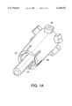
- FIG. 1A illustrates a bottom view of an impression coping device of the invention.
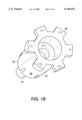
- FIG. 1B illustrates a top view of an impression coping device of the invention.
- FIG. 2A is a side view of an impression coping device of the invention.
- FIG. 2B is a cross-sectional view of the device shown in FIG. 2A.
- FIG. 3 is a bottom view of an impression coping device of the invention.
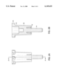
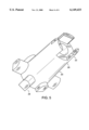
- FIG. 4 is a stylized side view of an impression coping device of the invention.
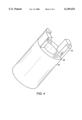
- FIG. 5 is a side view of an impression coping device of the invention.
- the invention relates to an improved impression coping device for establishing the relative position of a dental implant.
- the coping device has spaced-apart castellated fingers at the point of attachment to a dental fixture. The spaced-apart fingers allow visual inspection of the attached coping device.
- a device of the invention releasably attaches to a dental fixture by a friction-fit mating, a snap-fit mating, a threaded mating, or other mating means.
- a fastener e.g., a screw
- the device may be inserted and removed without disturbing its rotational alignment with respect to the existing dentition. This makes it quicker and easier for a practitioner to make an impression of the local dentition that is useful for construction of a replacement tooth that has the same geometric architecture as the surrounding area into which the replacement tooth is placed.
- an impression coping device of the invention may take many forms, depending, inter alia, on the dental fixture with which it mates, the location into which a replacement tooth is placed, the surface area necessary or desirable for anchoring an impression, and other factors known to the skilled person. Described below is a preferred embodiment of the invention for use with standard dental fixtures.
- a preferred device of the invention comprises a head having a first end that releasably attaches to a dental fixture.
- the first end preferably is castellated, as shown in FIGS. 1A and 1B.
- the castellated end comprises a plurality of axially extending, radially resilient fingers that deflect as they are friction fitted over a mating surface of a dental fixture.
- the castellated end comprises an inner surface which corresponds to mating detail on the surface of a dental fixture. Expansion of the fingers causes the castellated end to radially friction fit onto the reciprocal mating surface of the fixture.
- the radial friction fit between corresponding mating surfaces of the impression coping device and the dental fixture allows releasable attachment of the device to the dental fixture with or without the use of screws.
- the orientation and alignment of an impression of the local dentition are preserved.
- FIG. 1A A preferred impression coping device of the invention is shown in FIG. 1A. It has a first end comprising a head 10 that is substantially frusto-conical or cylindrical in shape.
- the head has a castellated end 18, which has a hexagonal inner surface for mating with a corresponding surface of a dental fixture (not shown).
- the castellated end of the head comprises axially-extending, radially-resilient fingers 12, which form a flexible hexagonal inner surface for providing a radial friction fit with a corresponding dental fixture mating surface.
- FIG. 3 shows a hexagonal mating detail of a device of the invention.
- Like reference numerals in FIGS. 1B and 3 refer to like elements in FIG. 1A.
- the hexagonal mating detail makes reciprocal contact with a corresponding mating detail on a dental fixture in order to hold the impression coping device in place.
- FIG. 5 A particularly-preferred impression coping device of the invention is shown in FIG. 5.
- the device has a first end comprising a head 20 that is substantially frusto-conical or cylindrical in shape.
- the head has a castellated end 28, which has an inner surface that is complementary to a hexagon for mating with a corresponding surface of a dental fixture (not shown).
- the castellated end of the head preferably comprises three spaced-apart axially-extending, radially resilient fingers 22, which form a flexible inner surface that is complementary to a hexagon for providing a radial friction fit with a corresponding dental fixture mating surface.
- FIG. 4 shows an alternative embodiment of the impression coping device with two axially-extending, radially resilient fingers.
- the spacing between fingers allows visual inspection of the coping device as attached to the fixture.
- the ability to visually inspect the attached device/fixture ensures that a proper mating has been achieved between the coping and the fixture (i.e., that the mating has retained proper geometry for taking an accurate impression).
- the spacing between fingers can be any distance that allows for visual inspection of the coping device as attached to the fixture.
- a preferred spacing of the fingers is between 0.5 mm and 3 mm.
- a particularly preferred spacing is between 1 mm and 2 mm.
- a second end of the head comprises one or more radially arranged flanges 16. These are arranged to provide an anchor for impression molding material applied to the dentition in the vicinity of the replacement site.
- the flanges provide surface area for attachment of the molding material, thereby facilitating its removal from the mouth upon curing.
- an impression coping device of the invention is constructed from a biologically compatible material.
- biologically compatible materials include, but are not limited to, polycarbonate, high-impact polystyrene, and polyetherimide.
- An impression coping device of the invention is made by well-known processes. Such processes include, for example, injection-molding or stereolithography. The precise method for manufacturing an impression coping device of the invention is immaterial to practice of the invention, as long as a device results from such process that forms a releasable friction fit with a dental fixture, as described above.
- An impression coping device of the invention is used as an aid in performing a single or multiple tooth restoration.
- a study cast of a patient's existing teeth is first made.
- a dental fixture such as that manufactured by Life Core, is implanted in a bore hole made in a patient's jaw at the site of desired tooth replacement.
- the implant site is surgically prepared by drilling into the jawbone after the gingival tissue surrounding the point of insertion of the implant has been retracted.
- a preferred dental fixture comprises a male hexagonal interface at its exposed end and is therefore compatible with an impression coping device of the invention having a female hexagonal interface on the castellated end of the head.
- the dental fixture also contains a hollow bore, which is open from the exposed end of the fixture and extends into the fixture.
- the hollow portion of the implant fixture may or may not have inner screw threads.
- a coping device of the invention is attached to the implanted dental fixture using a radial friction fit that is formed between the castellated end of the impression coping device and the corresponding hexagonal mating end of the dental fixture.
- the fingers of the castellated end expand as the device is forced over the male hexagonal interface of the fixture.
- the radial friction fit between the two hexagonal interfaces prevents the coping device from rotating on the fixture.
- a snap-fit connection may be used in which the mating end of the impression coping device comprises a lip that fits over the mating surface of the dental fixture, forming a removable or releasable communication between the two.
- the coping device of the invention is attached by a radial friction fit formed between the castellated end with three axially-extending, radially resilient fingers and the corresponding hexagonal mating end of the dental fixture.
- the three fingers provide for an easy visual determination of whether the coping device is properly engaged or seated with the dental fixture.
- the fingers of the castellated end expand as the device is forced over the male hexagonal interface of the fixture.
- the radial friction fit prevents the coping device from rotating on the fixture.
- a snap-fit connection may be used in which the mating end of the impression coping device comprises a lip that fits over the mating surface of the dental fixture, forming a removable or releasable connection between the two.
- Such a device is not clamped to a fixture, but is seated on the flats or "points" on the mating hex on the fixture, thereby providing a mating fit with resistance to rotation, but not requiring a clamping force.
- the spaced-apart fingers provide for easy visual determination of whether the coping device is properly engaged or seated with the dental fixture.
- the spacing between fingers can be any distance that allows for visual inspection of the coping device as attached to the fixture.
- a preferred spacing of the fingers is between 0.5 mm and 3 mm.
- a particularly preferred spacing is between 1 mm and 2 mm.
- a castellated end with two axially-extending, radially resilient fingers also is useful for visual determination of proper engagement or seating in either a friction-fit or snap-fit configuration.
- a fastener e.g., a screw
- an impression of the local dentition is made.
- An elastomeric impression material such as, for example, polyether siloxane or polyvinyl siloxane, is pressed onto the coping device and surrounding teeth. The impression preferably is made without contacting the gum tissue. The impression is allowed to harden for approximately one minute before removal.
- the impression coping device, and attached impression material are removed by pulling the coping away from the dental implant fixture. The coping and the impression are removed simultaneously.
- the gingival tissue is replaced over the bone and around the implanted dental fixture to promote healing. Healing generally occurs within about 4 to about 9 months.
- the impression coping device containing the attached impression material is attached to an analog fixture, which is then cast in a study cast previously made of the patient's mouth.
- the space surrounding the analog fixture is then filled and allowed to cure so that the analog fixture becomes part of the study cast.
- the rotational and positional alignment of the dental fixture is thus preserved with respect to the patient's natural dentition.
- a series of measurements are taken in order to guide the fabrication of an abutment and crown that closely approximate the tooth being replaced. Measurements are taken from all directions with respect to the angles of adjacent teeth and/or face construction. Measurements required to fabricate and position abutments for teeth are provided, for example, in Wheeler, Dental Anatomy, Physiology and Occlusion (5th ed. 1974), incorporated by reference herein. Measurements may be taken by several means including, but not limited to, a stent, a mold of the teeth, an optical device, or other measuring instrument.
- an abutment is fabricated for insertion into the implanted dental fixture. Measurements may be made using a computerized abutment model, as disclosed in co-owned, co-pending U.S. patent application Ser. No. 08/372,323, incorporated by reference herein.
- the computer model is based on general abutment parameters for the particular tooth or teeth being replaced.
- a wax model of the abutment is created on, for example, a Sanders Prototype, Inc. Model Maker 6 Pro® rapid prototyping machine.
- a crown that approximates the size and color of the patient's natural teeth is fabricated to fit over the abutment.
- a dental technician sculpts the crown with reference to the previously-prepared analog fixture and abutment.
- the crown is sculpted from, for example, wax or ceramic.
- the abutment is screwed into place in the dental fixture.
- the crown is attached to the abutment with an adhesive and/or a lateral set screw.
- An implant restoration is, therefore, performed without the necessity of screwing an impression coping into a dental fixture implanted in a patient's jaw.
- the impression coping device of the invention makes it quicker and easier for a practitioner to prepare a crown and abutment, while preserving the exact rotational and positional alignment of the patient's natural dentition.
Abstract
Description
Claims (10)
Priority Applications (3)
| Application Number | Priority Date | Filing Date | Title |
|---|---|---|---|
| US09/184,730 US6149433A (en) | 1997-05-05 | 1998-11-02 | One-piece impression coping for customized implant restorative systems |
| US09/663,728 US6540516B1 (en) | 1997-05-05 | 2000-09-15 | Impression coping platform and related methods |
| US09/662,700 US6524106B1 (en) | 1997-05-05 | 2000-09-15 | Fastener for attaching to a dental fixture and related methods |
Applications Claiming Priority (2)
| Application Number | Priority Date | Filing Date | Title |
|---|---|---|---|
| US08/851,836 US5829981A (en) | 1997-05-05 | 1997-05-05 | One-piece impression coping for customized implant restorative systems |
| US09/184,730 US6149433A (en) | 1997-05-05 | 1998-11-02 | One-piece impression coping for customized implant restorative systems |
Related Parent Applications (1)
| Application Number | Title | Priority Date | Filing Date |
|---|---|---|---|
| US08/851,836 Continuation-In-Part US5829981A (en) | 1997-05-05 | 1997-05-05 | One-piece impression coping for customized implant restorative systems |
Related Child Applications (2)
| Application Number | Title | Priority Date | Filing Date |
|---|---|---|---|
| US09/662,700 Continuation-In-Part US6524106B1 (en) | 1997-05-05 | 2000-09-15 | Fastener for attaching to a dental fixture and related methods |
| US09/663,728 Continuation-In-Part US6540516B1 (en) | 1997-05-05 | 2000-09-15 | Impression coping platform and related methods |
Publications (1)
| Publication Number | Publication Date |
|---|---|
| US6149433A true US6149433A (en) | 2000-11-21 |
Family
ID=26880423
Family Applications (1)
| Application Number | Title | Priority Date | Filing Date |
|---|---|---|---|
| US09/184,730 Expired - Lifetime US6149433A (en) | 1997-05-05 | 1998-11-02 | One-piece impression coping for customized implant restorative systems |
Country Status (1)
| Country | Link |
|---|---|
| US (1) | US6149433A (en) |
Cited By (27)
| Publication number | Priority date | Publication date | Assignee | Title |
|---|---|---|---|---|
| US6524106B1 (en) | 1997-05-05 | 2003-02-25 | Atlantis Components, Inc. | Fastener for attaching to a dental fixture and related methods |
| US6540516B1 (en) | 1997-05-05 | 2003-04-01 | Atlantis Components, Inc. | Impression coping platform and related methods |
| US20040018469A1 (en) * | 2002-07-23 | 2004-01-29 | Robert Summers | Impression support system for dental implants |
| US20040120781A1 (en) * | 2002-12-19 | 2004-06-24 | Luca Silvio Castello Branco De | Customized instruments and parts for medical-dental applications and method and blank for on-site machining of same |
| US20040234926A1 (en) * | 2001-11-01 | 2004-11-25 | Astra Tech Ab | Components for improved impression making |
| US6951460B2 (en) | 2001-11-01 | 2005-10-04 | Astra Tech Ab | Components and method for improved impression making |
| US20060040236A1 (en) * | 2004-08-17 | 2006-02-23 | Schmitt Stephen M | Design and manufacture of dental implant restorations |
| US20070190492A1 (en) * | 2006-02-15 | 2007-08-16 | Dental Implant Technologies, Inc. | Computer machined dental tooth system and method |
| US20070190481A1 (en) * | 2006-02-15 | 2007-08-16 | Dental Implant Technologies, Inc. | Method For Making A Virtual Computer Model of the Jaws |
| US20070293965A1 (en) * | 2006-06-16 | 2007-12-20 | Searete Llc, A Limited Liability Corporation Of The State Of Delaware | Stent customization system and method |
| US20070293756A1 (en) * | 2006-06-16 | 2007-12-20 | Searete Llc | Specialty stents with flow control features or the like |
| US20080058633A1 (en) * | 2006-06-16 | 2008-03-06 | Searete Llc, A Limited Liability Corporation Of The State Of Delaware | Methods and systems for specifying a blood vessel sleeve |
| US20080064008A1 (en) * | 2006-09-06 | 2008-03-13 | Dental Implant Technologies, Inc. | Methods for the virtual design and computer manufacture of intra oral devices |
| US20080077265A1 (en) * | 2006-06-16 | 2008-03-27 | Searete Llc, A Limited Liability Corporation Of The State Of Delaware | Methods and systems for making a blood vessel sleeve |
| US20080082160A1 (en) * | 2006-06-16 | 2008-04-03 | Searete Llc, A Limited Liability Corporation Of The State Of Delaware | Rapid-prototyped custom-fitted blood vessel sleeve |
| US20080085489A1 (en) * | 2006-10-07 | 2008-04-10 | Dental Implant Technologies, Inc. | Surgical guides and methods for positioning artificial teeth and dental implants |
| US20080201007A1 (en) * | 2006-06-16 | 2008-08-21 | Searete Llc, A Limited Liability Corporation Of The State Of Delaware | Methods and systems for making a blood vessel sleeve |
| KR100857363B1 (en) * | 2006-09-14 | 2008-09-05 | 현대자동차주식회사 | Variable type torsion bar of Coupled Torsion Beam Axle suspension |
| US20080228303A1 (en) * | 2007-03-13 | 2008-09-18 | Schmitt Stephen M | Direct manufacture of dental and medical devices |
| US8002547B2 (en) | 2000-01-18 | 2011-08-23 | Biomet 3I Llc | Preparation coping for creating an accurate permanent post to support a final prosthesis and method for creating the same |
| US8163003B2 (en) | 2006-06-16 | 2012-04-24 | The Invention Science Fund I, Llc | Active blood vessel sleeve methods and systems |
| US20120135370A1 (en) * | 2009-01-19 | 2012-05-31 | Aeton Medical Llc | Transfer copings and related methods for taking implant impressions |
| US8348669B1 (en) | 2009-11-04 | 2013-01-08 | Bankruptcy Estate Of Voxelogix Corporation | Surgical template and method for positioning dental casts and dental implants |
| US8577693B2 (en) | 2011-07-13 | 2013-11-05 | The Invention Science Fund I, Llc | Specialty stents with flow control features or the like |
| US8636511B2 (en) | 2002-11-13 | 2014-01-28 | Biomet 3I, Llc | Dental implant system |
| US9737380B2 (en) | 2009-02-13 | 2017-08-22 | Aeton Medical Llc | Components for use with implants and related methods |
| US9925024B2 (en) | 2011-06-28 | 2018-03-27 | Biomet 3I, Llc | Dental implant and abutment tools |
Citations (29)
| Publication number | Priority date | Publication date | Assignee | Title |
|---|---|---|---|---|
| US4681542A (en) * | 1986-02-18 | 1987-07-21 | Lloyd Baum | Retention system for dental prosthesis |
| US4758161A (en) * | 1987-01-28 | 1988-07-19 | Core-Vent Corporation | Coping insert for use with a dental implant |
| US4955811A (en) * | 1988-06-23 | 1990-09-11 | Implant Innovations, Inc. | Non-rotational single-tooth prosthodontic restoration |
| US4988297A (en) * | 1988-03-01 | 1991-01-29 | Implant Innovations, Inc. | Alignment corrector for dental implants |
| US5052929A (en) * | 1990-03-02 | 1991-10-01 | Seal D Greg | Method for constructing a custom abutment for use in association with dental implants |
| US5104318A (en) * | 1990-09-20 | 1992-04-14 | 2848-4293 Quebec Inc. | Implant assembly for anchoring an artificial tooth |
| US5106300A (en) * | 1990-09-26 | 1992-04-21 | Voitik Anton J | Dental implant attachment structure and method |
| US5125839A (en) * | 1990-09-28 | 1992-06-30 | Abraham Ingber | Dental implant system |
| US5125841A (en) * | 1990-01-18 | 1992-06-30 | Nobelpharma Ab | Impression top |
| US5193999A (en) * | 1991-11-14 | 1993-03-16 | Attachments International, Inc. | Abutment selector |
| US5213502A (en) * | 1992-06-10 | 1993-05-25 | Fereidoun Daftary | Interlockable two-piece impression coping for anatomical dental abutment restorative systems |
| US5297963A (en) * | 1993-05-17 | 1994-03-29 | Fereidoun Dafatry | Anatomical restoration dental implant system with interlockable elliptical healing cap assembly and matching abutment member |
| US5334024A (en) * | 1990-03-21 | 1994-08-02 | Core-Vent Corporation | Transfer abutment |
| US5338196A (en) * | 1993-04-08 | 1994-08-16 | Implant Innovations, Inc. | Dental laboratory components and procedures for anatomical restoration on artificial root fixtures |
| US5362235A (en) * | 1993-05-17 | 1994-11-08 | Fereidoun Daftary | Anatomical restoration dental implant system with interlockable angled abutment assembly |
| US5362237A (en) * | 1991-08-02 | 1994-11-08 | Wellesley Research Associates, Inc. | Dental post construction |
| US5417568A (en) * | 1994-02-25 | 1995-05-23 | Giglio; Graziano D. | Gingival contoured abutment |
| US5447435A (en) * | 1991-09-18 | 1995-09-05 | Brodbeck; Urs | Device for the reconstruction of teeth |
| US5492471A (en) * | 1994-03-23 | 1996-02-20 | Gary Singer | Healing cap system |
| US5527182A (en) * | 1993-12-23 | 1996-06-18 | Adt Advanced Dental Technologies, Ltd. | Implant abutment systems, devices, and techniques |
| US5571015A (en) * | 1994-09-26 | 1996-11-05 | Siegmund; Ernie | Dental replacement mounting system |
| WO1996034576A1 (en) * | 1995-05-03 | 1996-11-07 | Astra Aktiebolag | Ball impression coping |
| US5658147A (en) * | 1995-09-19 | 1997-08-19 | Shopvest, Inc. | Working model for prosthodontic preparation of a crown for installation on an implant fixture |
| US5662476A (en) * | 1992-06-29 | 1997-09-02 | Nobel Biocare Ab | Prosthetic implant restoration method |
| US5674073A (en) * | 1996-01-30 | 1997-10-07 | Nobel Biocare Ab | Impression coping |
| US5685715A (en) * | 1995-03-10 | 1997-11-11 | Beaty; Keith D. | Self-indexing transfer impression coping |
| US5688123A (en) * | 1994-05-04 | 1997-11-18 | Degussa Aktiengesellschaft | Transfer cap for dental implants |
| US5829981A (en) * | 1997-05-05 | 1998-11-03 | Atlantis Components, Inc. | One-piece impression coping for customized implant restorative systems |
| US5938443A (en) * | 1994-11-08 | 1999-08-17 | Implant Innovations, Inc. | Impression coping for use in an open tray and closed tray impression methodology |
-
1998
- 1998-11-02 US US09/184,730 patent/US6149433A/en not_active Expired - Lifetime
Patent Citations (31)
| Publication number | Priority date | Publication date | Assignee | Title |
|---|---|---|---|---|
| US4681542A (en) * | 1986-02-18 | 1987-07-21 | Lloyd Baum | Retention system for dental prosthesis |
| US4758161A (en) * | 1987-01-28 | 1988-07-19 | Core-Vent Corporation | Coping insert for use with a dental implant |
| US4988297A (en) * | 1988-03-01 | 1991-01-29 | Implant Innovations, Inc. | Alignment corrector for dental implants |
| US4955811A (en) * | 1988-06-23 | 1990-09-11 | Implant Innovations, Inc. | Non-rotational single-tooth prosthodontic restoration |
| US5125841A (en) * | 1990-01-18 | 1992-06-30 | Nobelpharma Ab | Impression top |
| US5052929A (en) * | 1990-03-02 | 1991-10-01 | Seal D Greg | Method for constructing a custom abutment for use in association with dental implants |
| US5334024A (en) * | 1990-03-21 | 1994-08-02 | Core-Vent Corporation | Transfer abutment |
| US5104318A (en) * | 1990-09-20 | 1992-04-14 | 2848-4293 Quebec Inc. | Implant assembly for anchoring an artificial tooth |
| US5106300A (en) * | 1990-09-26 | 1992-04-21 | Voitik Anton J | Dental implant attachment structure and method |
| US5125839A (en) * | 1990-09-28 | 1992-06-30 | Abraham Ingber | Dental implant system |
| US5362237A (en) * | 1991-08-02 | 1994-11-08 | Wellesley Research Associates, Inc. | Dental post construction |
| US5447435A (en) * | 1991-09-18 | 1995-09-05 | Brodbeck; Urs | Device for the reconstruction of teeth |
| US5193999A (en) * | 1991-11-14 | 1993-03-16 | Attachments International, Inc. | Abutment selector |
| US5213502A (en) * | 1992-06-10 | 1993-05-25 | Fereidoun Daftary | Interlockable two-piece impression coping for anatomical dental abutment restorative systems |
| US5662476A (en) * | 1992-06-29 | 1997-09-02 | Nobel Biocare Ab | Prosthetic implant restoration method |
| US5338196A (en) * | 1993-04-08 | 1994-08-16 | Implant Innovations, Inc. | Dental laboratory components and procedures for anatomical restoration on artificial root fixtures |
| US5476383A (en) * | 1993-04-08 | 1995-12-19 | Implant Innovations, Inc. | Dental restoration on artificial root fixtures |
| US5419702A (en) * | 1993-04-08 | 1995-05-30 | Implant Innovations, Inc. | Dental restoration on artificial root fixtures |
| US5362235A (en) * | 1993-05-17 | 1994-11-08 | Fereidoun Daftary | Anatomical restoration dental implant system with interlockable angled abutment assembly |
| US5297963A (en) * | 1993-05-17 | 1994-03-29 | Fereidoun Dafatry | Anatomical restoration dental implant system with interlockable elliptical healing cap assembly and matching abutment member |
| US5527182A (en) * | 1993-12-23 | 1996-06-18 | Adt Advanced Dental Technologies, Ltd. | Implant abutment systems, devices, and techniques |
| US5417568A (en) * | 1994-02-25 | 1995-05-23 | Giglio; Graziano D. | Gingival contoured abutment |
| US5492471A (en) * | 1994-03-23 | 1996-02-20 | Gary Singer | Healing cap system |
| US5688123A (en) * | 1994-05-04 | 1997-11-18 | Degussa Aktiengesellschaft | Transfer cap for dental implants |
| US5571015A (en) * | 1994-09-26 | 1996-11-05 | Siegmund; Ernie | Dental replacement mounting system |
| US5938443A (en) * | 1994-11-08 | 1999-08-17 | Implant Innovations, Inc. | Impression coping for use in an open tray and closed tray impression methodology |
| US5685715A (en) * | 1995-03-10 | 1997-11-11 | Beaty; Keith D. | Self-indexing transfer impression coping |
| WO1996034576A1 (en) * | 1995-05-03 | 1996-11-07 | Astra Aktiebolag | Ball impression coping |
| US5658147A (en) * | 1995-09-19 | 1997-08-19 | Shopvest, Inc. | Working model for prosthodontic preparation of a crown for installation on an implant fixture |
| US5674073A (en) * | 1996-01-30 | 1997-10-07 | Nobel Biocare Ab | Impression coping |
| US5829981A (en) * | 1997-05-05 | 1998-11-03 | Atlantis Components, Inc. | One-piece impression coping for customized implant restorative systems |
Non-Patent Citations (2)
| Title |
|---|
| Wheeler, Dental Anatomy, Physiology and Occlusion 3 23 (Fifth Edition, 1974). * |
| Wheeler, Dental Anatomy, Physiology and Occlusion 3-23 (Fifth Edition, 1974). |
Cited By (58)
| Publication number | Priority date | Publication date | Assignee | Title |
|---|---|---|---|---|
| US6524106B1 (en) | 1997-05-05 | 2003-02-25 | Atlantis Components, Inc. | Fastener for attaching to a dental fixture and related methods |
| US6540516B1 (en) | 1997-05-05 | 2003-04-01 | Atlantis Components, Inc. | Impression coping platform and related methods |
| US8002547B2 (en) | 2000-01-18 | 2011-08-23 | Biomet 3I Llc | Preparation coping for creating an accurate permanent post to support a final prosthesis and method for creating the same |
| US20040234926A1 (en) * | 2001-11-01 | 2004-11-25 | Astra Tech Ab | Components for improved impression making |
| US6824386B2 (en) | 2001-11-01 | 2004-11-30 | Astra Tech Ab | Components for improved impression making |
| US6951460B2 (en) | 2001-11-01 | 2005-10-04 | Astra Tech Ab | Components and method for improved impression making |
| US20040018469A1 (en) * | 2002-07-23 | 2004-01-29 | Robert Summers | Impression support system for dental implants |
| US6905336B2 (en) | 2002-07-23 | 2005-06-14 | Robert Summers | Impression support system for dental implants |
| US9883927B2 (en) | 2002-11-13 | 2018-02-06 | Biomet 3I, Llc | Dental implant system |
| US9931182B2 (en) | 2002-11-13 | 2018-04-03 | Biomet 3I, Llc | Dental implant system |
| US9549793B2 (en) | 2002-11-13 | 2017-01-24 | Biomet 3I, Llc | Dental implant system |
| US8636511B2 (en) | 2002-11-13 | 2014-01-28 | Biomet 3I, Llc | Dental implant system |
| US20040120781A1 (en) * | 2002-12-19 | 2004-06-24 | Luca Silvio Castello Branco De | Customized instruments and parts for medical-dental applications and method and blank for on-site machining of same |
| US7322824B2 (en) | 2004-08-17 | 2008-01-29 | Schmitt Stephen M | Design and manufacture of dental implant restorations |
| US20060040236A1 (en) * | 2004-08-17 | 2006-02-23 | Schmitt Stephen M | Design and manufacture of dental implant restorations |
| US20070190492A1 (en) * | 2006-02-15 | 2007-08-16 | Dental Implant Technologies, Inc. | Computer machined dental tooth system and method |
| US20070190481A1 (en) * | 2006-02-15 | 2007-08-16 | Dental Implant Technologies, Inc. | Method For Making A Virtual Computer Model of the Jaws |
| US8366442B2 (en) | 2006-02-15 | 2013-02-05 | Bankruptcy Estate Of Voxelogix Corporation | Dental apparatus for radiographic and non-radiographic imaging |
| US8043091B2 (en) | 2006-02-15 | 2011-10-25 | Voxelogix Corporation | Computer machined dental tooth system and method |
| US8430922B2 (en) | 2006-06-16 | 2013-04-30 | The Invention Science Fund I, Llc | Stent customization system and method |
| US8163003B2 (en) | 2006-06-16 | 2012-04-24 | The Invention Science Fund I, Llc | Active blood vessel sleeve methods and systems |
| US20080058633A1 (en) * | 2006-06-16 | 2008-03-06 | Searete Llc, A Limited Liability Corporation Of The State Of Delaware | Methods and systems for specifying a blood vessel sleeve |
| US20070293965A1 (en) * | 2006-06-16 | 2007-12-20 | Searete Llc, A Limited Liability Corporation Of The State Of Delaware | Stent customization system and method |
| US20080077265A1 (en) * | 2006-06-16 | 2008-03-27 | Searete Llc, A Limited Liability Corporation Of The State Of Delaware | Methods and systems for making a blood vessel sleeve |
| US20080082160A1 (en) * | 2006-06-16 | 2008-04-03 | Searete Llc, A Limited Liability Corporation Of The State Of Delaware | Rapid-prototyped custom-fitted blood vessel sleeve |
| US20070293756A1 (en) * | 2006-06-16 | 2007-12-20 | Searete Llc | Specialty stents with flow control features or the like |
| US20080201007A1 (en) * | 2006-06-16 | 2008-08-21 | Searete Llc, A Limited Liability Corporation Of The State Of Delaware | Methods and systems for making a blood vessel sleeve |
| US20070294150A1 (en) * | 2006-06-16 | 2007-12-20 | Searete Llc, A Limited Liability Corporation Of The State Of Delaware | Specialty stents with flow control features or the like |
| US8721706B2 (en) | 2006-06-16 | 2014-05-13 | The Invention Science Fund I, Llc | Specialty stents with flow control features or the like |
| US20090084844A1 (en) * | 2006-06-16 | 2009-04-02 | Jung Edward K Y | Specialty stents with flow control features or the like |
| US7769603B2 (en) | 2006-06-16 | 2010-08-03 | The Invention Science Fund I, Llc | Stent customization system and method |
| US7818084B2 (en) | 2006-06-16 | 2010-10-19 | The Invention Science Fund, I, LLC | Methods and systems for making a blood vessel sleeve |
| US20070294279A1 (en) * | 2006-06-16 | 2007-12-20 | Searete Llc, A Limited Liability Corporation Of The State Of Delaware | Stent customization system and method |
| US8551155B2 (en) | 2006-06-16 | 2013-10-08 | The Invention Science Fund I, Llc | Stent customization system and method |
| US20070293966A1 (en) * | 2006-06-16 | 2007-12-20 | Searete Llc, A Limited Liability Corporation Of The State Of Delaware | Specialty stents with flow control features or the like |
| US20070294152A1 (en) * | 2006-06-16 | 2007-12-20 | Searete Llc, A Limited Liability Corporation Of The State Of Delaware | Specialty stents with flow control features or the like |
| US8095382B2 (en) | 2006-06-16 | 2012-01-10 | The Invention Science Fund I, Llc | Methods and systems for specifying a blood vessel sleeve |
| US8147537B2 (en) | 2006-06-16 | 2012-04-03 | The Invention Science Fund I, Llc | Rapid-prototyped custom-fitted blood vessel sleeve |
| US20070294151A1 (en) * | 2006-06-16 | 2007-12-20 | Searete Llc, A Limited Liability Corporation Of The State Of Delaware | Specialty stents with flow control features or the like |
| US8550344B2 (en) | 2006-06-16 | 2013-10-08 | The Invention Science Fund I, Llc | Specialty stents with flow control features or the like |
| US8478437B2 (en) | 2006-06-16 | 2013-07-02 | The Invention Science Fund I, Llc | Methods and systems for making a blood vessel sleeve |
| US8475517B2 (en) | 2006-06-16 | 2013-07-02 | The Invention Science Fund I, Llc | Stent customization system and method |
| US20070294280A1 (en) * | 2006-06-16 | 2007-12-20 | Searete Llc, A Limited Liability Corporation Of The State Of Delaware | Stent customization system and method |
| US20070293963A1 (en) * | 2006-06-16 | 2007-12-20 | Searete Llc, A Limited Liability Corporation Of The State Of Delaware | Stent customization system and method |
| US20080064008A1 (en) * | 2006-09-06 | 2008-03-13 | Dental Implant Technologies, Inc. | Methods for the virtual design and computer manufacture of intra oral devices |
| KR100857363B1 (en) * | 2006-09-14 | 2008-09-05 | 현대자동차주식회사 | Variable type torsion bar of Coupled Torsion Beam Axle suspension |
| US8364301B2 (en) | 2006-10-07 | 2013-01-29 | Bankruptcy Estate Of Voxelogix Corporation | Surgical guides and methods for positioning artificial teeth and dental implants |
| US20080085489A1 (en) * | 2006-10-07 | 2008-04-10 | Dental Implant Technologies, Inc. | Surgical guides and methods for positioning artificial teeth and dental implants |
| US20110066267A1 (en) * | 2006-10-07 | 2011-03-17 | Schmitt Stephen M | Surgical guides and methods for positioning artificial teeth and dental implants |
| US7835811B2 (en) | 2006-10-07 | 2010-11-16 | Voxelogix Corporation | Surgical guides and methods for positioning artificial teeth and dental implants |
| US20080228303A1 (en) * | 2007-03-13 | 2008-09-18 | Schmitt Stephen M | Direct manufacture of dental and medical devices |
| US8936468B2 (en) * | 2009-01-19 | 2015-01-20 | Roger S. Ranck | Transfer copings and related methods for taking implant impressions |
| US20120135370A1 (en) * | 2009-01-19 | 2012-05-31 | Aeton Medical Llc | Transfer copings and related methods for taking implant impressions |
| US9737380B2 (en) | 2009-02-13 | 2017-08-22 | Aeton Medical Llc | Components for use with implants and related methods |
| US8348669B1 (en) | 2009-11-04 | 2013-01-08 | Bankruptcy Estate Of Voxelogix Corporation | Surgical template and method for positioning dental casts and dental implants |
| US9925024B2 (en) | 2011-06-28 | 2018-03-27 | Biomet 3I, Llc | Dental implant and abutment tools |
| US10952826B2 (en) | 2011-06-28 | 2021-03-23 | Biomet 3I, Llc | System and method of dental implant and interface to abutment for restoration |
| US8577693B2 (en) | 2011-07-13 | 2013-11-05 | The Invention Science Fund I, Llc | Specialty stents with flow control features or the like |
Similar Documents
| Publication | Publication Date | Title |
|---|---|---|
| US6149433A (en) | One-piece impression coping for customized implant restorative systems | |
| US5829981A (en) | One-piece impression coping for customized implant restorative systems | |
| US6382977B1 (en) | Snap-in impression coping | |
| US6283752B1 (en) | Universal impression coping system | |
| US5674073A (en) | Impression coping | |
| US6666684B1 (en) | Impression and foundation system for implant-supported prosthesis | |
| US5052929A (en) | Method for constructing a custom abutment for use in association with dental implants | |
| EP1317221B1 (en) | Impression cap | |
| USRE43470E1 (en) | Dental implant systems and methods | |
| US6824386B2 (en) | Components for improved impression making | |
| US6951460B2 (en) | Components and method for improved impression making | |
| US5915962A (en) | Dental implant and prosthesis positioning | |
| EP0879023B1 (en) | Emergence profile system having a combined healing abutment and impression coping | |
| US5106300A (en) | Dental implant attachment structure and method | |
| US5651675A (en) | Healing cap system | |
| US20070281278A1 (en) | Transfer coping for dental implants | |
| US6672871B2 (en) | Coping with standoffs | |
| US20060121416A1 (en) | Multiple use impression coping | |
| US5755574A (en) | Endosseous dental implant and method of manufacture | |
| JP2012517861A (en) | Components used with implants and associated methods | |
| AU2002347710A1 (en) | Components and method for improved impression making | |
| EP0288445B1 (en) | A socket for carrying a dental prosthesis | |
| US6540516B1 (en) | Impression coping platform and related methods | |
| US20190247149A1 (en) | Custom dental component and scan body | |
| US6524106B1 (en) | Fastener for attaching to a dental fixture and related methods |
Legal Events
| Date | Code | Title | Description |
|---|---|---|---|
| AS | Assignment |
Owner name: ATLANTIS COMPONENTS, INC., MASSACHUSETTS Free format text: ASSIGNMENT OF ASSIGNORS INTEREST;ASSIGNORS:ZIEGLER, ANDREW;COLE, THOMAS J.;REEL/FRAME:009712/0439;SIGNING DATES FROM 19990113 TO 19990119 |
|
| STCF | Information on status: patent grant |
Free format text: PATENTED CASE |
|
| FEPP | Fee payment procedure |
Free format text: PAYOR NUMBER ASSIGNED (ORIGINAL EVENT CODE: ASPN); ENTITY STATUS OF PATENT OWNER: LARGE ENTITY |
|
| FPAY | Fee payment |
Year of fee payment: 4 |
|
| FEPP | Fee payment procedure |
Free format text: PAYER NUMBER DE-ASSIGNED (ORIGINAL EVENT CODE: RMPN); ENTITY STATUS OF PATENT OWNER: LARGE ENTITY Free format text: PAYOR NUMBER ASSIGNED (ORIGINAL EVENT CODE: ASPN); ENTITY STATUS OF PATENT OWNER: LARGE ENTITY |
|
| FEPP | Fee payment procedure |
Free format text: PAYER NUMBER DE-ASSIGNED (ORIGINAL EVENT CODE: RMPN); ENTITY STATUS OF PATENT OWNER: LARGE ENTITY Free format text: PAYOR NUMBER ASSIGNED (ORIGINAL EVENT CODE: ASPN); ENTITY STATUS OF PATENT OWNER: LARGE ENTITY Free format text: PAT HOLDER NO LONGER CLAIMS SMALL ENTITY STATUS, ENTITY STATUS SET TO UNDISCOUNTED (ORIGINAL EVENT CODE: STOL); ENTITY STATUS OF PATENT OWNER: LARGE ENTITY |
|
| REFU | Refund |
Free format text: REFUND - PAYMENT OF MAINTENANCE FEE, 8TH YR, SMALL ENTITY (ORIGINAL EVENT CODE: R2552); ENTITY STATUS OF PATENT OWNER: LARGE ENTITY |
|
| FPAY | Fee payment |
Year of fee payment: 8 |
|
| FPAY | Fee payment |
Year of fee payment: 12 |