US6068301A - Method and apparatus for impeding the counterfeiting of cards, instruments and documents - Google Patents

Method and apparatus for impeding the counterfeiting of cards, instruments and documents Download PDF

Info

Publication number
US6068301A
US6068301A US09/084,844 US8484498A US6068301A US 6068301 A US6068301 A US 6068301A US 8484498 A US8484498 A US 8484498A US 6068301 A US6068301 A US 6068301A
Authority
US
United States
Prior art keywords
card
mark
instrument
issuance
marks
Prior art date
Legal status (The legal status is an assumption and is not a legal conclusion. Google has not performed a legal analysis and makes no representation as to the accuracy of the status listed.)
Expired - Fee Related
Application number
US09/084,844
Inventor
Wenyu Han
Victor Zazzu
Current Assignee (The listed assignees may be inaccurate. Google has not performed a legal analysis and makes no representation or warranty as to the accuracy of the list.)
Individual
Original Assignee
Individual
Priority date (The priority date is an assumption and is not a legal conclusion. Google has not performed a legal analysis and makes no representation as to the accuracy of the date listed.)
Filing date
Publication date
Application filed by Individual filed Critical Individual
Priority to US09/084,844 priority Critical patent/US6068301A/en
Priority to US09/300,969 priority patent/US6354506B1/en
Priority to PCT/US1999/011524 priority patent/WO1999062027A1/en
Priority to AU42036/99A priority patent/AU4203699A/en
Priority to CA002297830A priority patent/CA2297830A1/en
Priority to EP99925823A priority patent/EP1010135A1/en
Priority to JP2000551357A priority patent/JP2002517046A/en
Priority to US09/434,959 priority patent/US6135355A/en
Application granted granted Critical
Publication of US6068301A publication Critical patent/US6068301A/en
Anticipated expiration legal-status Critical
Expired - Fee Related legal-status Critical Current

Links

Images

Classifications

    • GPHYSICS
    • G06COMPUTING; CALCULATING OR COUNTING
    • G06KGRAPHICAL DATA READING; PRESENTATION OF DATA; RECORD CARRIERS; HANDLING RECORD CARRIERS
    • G06K19/00Record carriers for use with machines and with at least a part designed to carry digital markings
    • G06K19/06Record carriers for use with machines and with at least a part designed to carry digital markings characterised by the kind of the digital marking, e.g. shape, nature, code
    • G06K19/067Record carriers with conductive marks, printed circuits or semiconductor circuit elements, e.g. credit or identity cards also with resonating or responding marks without active components
    • G06K19/07Record carriers with conductive marks, printed circuits or semiconductor circuit elements, e.g. credit or identity cards also with resonating or responding marks without active components with integrated circuit chips
    • G06K19/077Constructional details, e.g. mounting of circuits in the carrier
    • G06K19/07716Constructional details, e.g. mounting of circuits in the carrier the record carrier comprising means for customization, e.g. being arranged for personalization in batch
    • GPHYSICS
    • G06COMPUTING; CALCULATING OR COUNTING
    • G06KGRAPHICAL DATA READING; PRESENTATION OF DATA; RECORD CARRIERS; HANDLING RECORD CARRIERS
    • G06K17/00Methods or arrangements for effecting co-operative working between equipments covered by two or more of main groups G06K1/00 - G06K15/00, e.g. automatic card files incorporating conveying and reading operations
    • GPHYSICS
    • G06COMPUTING; CALCULATING OR COUNTING
    • G06KGRAPHICAL DATA READING; PRESENTATION OF DATA; RECORD CARRIERS; HANDLING RECORD CARRIERS
    • G06K19/00Record carriers for use with machines and with at least a part designed to carry digital markings
    • G06K19/06Record carriers for use with machines and with at least a part designed to carry digital markings characterised by the kind of the digital marking, e.g. shape, nature, code
    • G06K19/08Record carriers for use with machines and with at least a part designed to carry digital markings characterised by the kind of the digital marking, e.g. shape, nature, code using markings of different kinds or more than one marking of the same kind in the same record carrier, e.g. one marking being sensed by optical and the other by magnetic means
    • G06K19/10Record carriers for use with machines and with at least a part designed to carry digital markings characterised by the kind of the digital marking, e.g. shape, nature, code using markings of different kinds or more than one marking of the same kind in the same record carrier, e.g. one marking being sensed by optical and the other by magnetic means at least one kind of marking being used for authentication, e.g. of credit or identity cards
    • G06K19/18Constructional details

Definitions

  • This invention relates to valuable cards, instruments and documents and, in particular, to a method and apparatus for preventing the counterfeiting and falsification of these cards, instruments and documents.
  • cards such as debit cards (or cash value cards) which are issued to individuals in payment of a certain sum of money.
  • debit cards are also referred to as cash value cards or cash cards since they may be redeemed for cash or the equivalent in goods and/or services.
  • a card holder uses the card when making withdrawals at a money dispensing or card acceptance machine.
  • FIG. 8A a person may insert cash ($) into a card vending machine 95 and the card vending machine will issue a debit or cash value card 100.
  • the purchaser of the card can insert the card 100 into a cash dispensing (card accepting) machine 97 to withdraw all or part of the cash value of the card 100.
  • each time the card holder makes a withdrawal a hole is punched through the card to indicate the amount of the withdrawal. For example, assume that a card issued for payment of $2,000.00 has a value of $2,000.00 and that the $2000.00 card is arranged to have 20 units with each unit representing a value of $100.00. A card holder may then make partial cash withdrawals (receive payment) in units of $100.00, or the card holder may receive goods (e.g., tokens, chips, balls) or services meted out in units of $100.00. For each unit (e.g., $100.00) withdrawn, a hole is punched in the card to indicate that the value of the card has been decreased by one unit (e.g., $100.00). If a card has a value of 20 units, there can be a maximum of 20 unit holes punched in the card to indicate that the entire value of the card has been used up.
  • goods e.g., tokens, chips, balls
  • a card 100 is shown in FIG. 1.
  • the card has a strip 102 along which holes may be punched.
  • an issuance hole 1A is punched into the card by the card vending machine 95 at the time of the issuance of the card so as to validate the card.
  • 20 additional holes (2-21) may be punched into the card by the cash dispensing machine 97 each time a withdrawal is made.
  • Hole number 2 is punched into the card after the first unit value is used up (e.g., $100.00 is withdrawn).
  • hole number 3 is punched into the card after the second unit value is used up (e.g., another $100.00 is withdrawn), and so on.
  • a problem with the above scheme is that it is possible to falsify the value of the card by simply filling in the holes of the cards using an opaque material. After the holes in the card have been filled up, the counterfeiter (thief) can reuse the card as if it were new and make cash (or the equivalent) withdrawals for the full value of the underlying card. The counterfeiter can then reuse the card an indefinite number of times.
  • a counterfeiter may reuse a canceled card by cutting off a portion of the top of the hologram stripe (e.g., section 101A) above the holes; and then pasting the portion of the hologram stripe (101A) on the portion (101B) of a previously canceled card so that the holes are covered.
  • a counterfeiter may produce a false hologram to place over a strip 101 even though its placement in an appropriate manner so as to fool a dispensing machine presents a significant problem.
  • the counterfeiting process is then normally completed by punching an issuance hole in the first position (i.e., the card issuance position).
  • An object of the invention is to make the falsification of the value of a cash card or the counterfeiting of such cards extremely difficult, if not impossible.
  • the cash card is an example of a particular application of the invention. It is an object of the invention to impede the counterfeiting and/or falsification of any valuable instrument/card/document. Therefore, note that in the discussion to follow and in the appended claims, when the term “instrument” is used without limitation, it is intended that the term “card” or “document” be included and vice-versa.
  • a card, instrument or document is encoded with first and second marks with the distance between the first mark and the second mark being programmable, such that the distance between the first mark and the second mark may be different for different cards (instruments or documents).
  • the first mark may be a reference mark and the second mark may be an issuance mark.
  • the issuance mark used in the embodiments is an "issuance hole". However, it should be understood that, in practicing the invention, any suitable "issuance mark" may be used instead of an issuance hole.
  • the location of the issuance hole may be selected to be placed anywhere on a card. In other embodiments, the location of the issuance hole may be any one of "N" possible hole locations located along a row or strip of a card; where N may be any integer greater than one.
  • the reference mark may be any number of different indicia and may be formed such that different points, or parts, of the reference mark may be used as the reference point to measure the distance to the issuance hole.
  • the reference mark is a hologram. In other embodiments, the reference mark is a bar code image (which may be visible or invisible to the naked eye). In still other embodiments, the reference mark may be a graphic image. In still other embodiments, the reference mark may be a "reference" hole.
  • the cash cards include a magnetic strip on which is written encoded information pertaining to the relationship between the reference mark and the issuance hole.
  • a card vending machine may be programmed to locate (or form) a reference mark on a card and to form an issuance mark on the card at different distances relative to the reference mark.
  • the information relating to the distance is encoded (encrypted) and stored in an information storage medium (e.g., a magnetic stripe) located on the card.
  • a user may use the card containing the reference and issuance marks to obtain either cash, goods or services from a dispensing machine programmed to read and decode the information stored in the storage medium.
  • FIG. 1 illustrates one side of a cash (value) card
  • FIG. 2 shows the one side of a cash card with a hologram stripe and a row of punched holes
  • FIG. 3 shows the one side of a cash card with a holographic image formed within the hologram stripe
  • FIG. 4 illustrates one side of a cash card with a reference mark used to define the location of an issuance hole
  • FIG. 5 illustrates one side of a cash card with a bar code used to define the location of an issuance hole
  • FIG. 6 illustrates one side of a cash card on which is formed a holostripe on top of a magnetic stripe
  • FIG. 6A illustrates the use of different storage mediums on a card
  • FIG. 7 illustrates one side of a cash card and different points which may be used to locate the issuance hole
  • FIG. 8A is a very basic block diagram of a card vending (card producing) machine
  • FIG. 8B is a very basic block diagram of a cash dispensing (card accepting) machine
  • FIG. 9A is a simplified block diagram of a portion of a card vending machine modified in accordance with the invention.
  • FIG. 9B is a simplified block diagram of a portion of a vending machine modified in accordance with the invention.
  • FIG. 9A a "blank" card (a card to be annotated) 100a is propagated along a motorized carriage 190 through the machine 95A.
  • the machine includes a microcontroller 191 which supplies critical signals to a reference image (mark) generator 192, an issuance mark generator 193 and a data encoder and writer 194.
  • the reference mark generator 192 places a reference mark, whose shape may also be controlled and programmably altered, onto the card.
  • the issuance mark generator 193 then places an issuance mark on the card of a shape and at a location programmably controlled by controller 191.
  • the distance "d" between the reference mark, or an arbitrary point on the reference mark, and the issuance mark is then determined by the controller 191.
  • the controller 191 includes, in combination with a data encoder and writer 194, means for encoding the data and then writing the encoded information onto the card.
  • the controller 191 may be programmed to vary the shape and location of the reference mark. Likewise, the controller 191 may be programmed to vary the location of the issuance mark relative to the reference mark. The spacing (distance) between the reference and issuance marks may be sensed by the distance programmer 195 coupled to the controller 191 which then decodes the information and supplies it to data writer 194. The controller may also be programmed to vary the shape of the reference mark to further increase the difficulty of counterfeiting the mark.
  • the reference and/or issuance marks may be: holes punched in the card; graphic symbols engraved or burned into the card; holographic images; or any other indicia which is machine readable or which may be rendered machine readable.
  • the dispensing (card accepting) machine may be modified as shown in FIG. 9B.
  • the dispensing machine 97A includes a sensor 201 to sense the reference mark location, a sensor 202 to sense the location of the issuance mark and a data reader (decoder) 203. Sensors 201 and 202, and reader/decoder 203 are coupled to a controller/checker 204.
  • the reader/decoder 203 reads (senses) the stored information written in a magnetic strip (or other storage medium) located on the card.
  • the controller 204 is provided with the information about the shapes of the reference and issuance marks and the distance between these marks.
  • the reference mark sensor 201 senses information regarding the location and shape of the reference mark which it senses and feeds this information to the controller.
  • the issuance mark sensor 202 senses information regarding the location and shape of the issuance mark which it sees and feeds this information to the controller 204.
  • the controller 204 evaluates the information received from sensors 201, 202 and 203 and compares the received information to the information received from reader/decoder 203. If the information matches, controller/checker 204 signals the dispenser to issue cash, goods or services. If the information does not match, controller/checker 204 will send an alarm indicative of the presence of a false card.
  • the location of the issuance hole is programmed to be placed in any one of N predetermined positions on a card such as shown in FIGS. 1 and 2, where the N holes will be punched along the strip 102 or 101 and N is any integer greater than one.
  • N is any integer greater than one.
  • a card vending machine such as 95A in FIG. 9A may be programmed to locate the issuance hole in any one of 21 possible positions.
  • the location of the issuance hole is then encoded (encrypted) by the vending machine and then written (stored) by the machine onto a magnetic stripe (see FIG.
  • the card issuance hole may be located in any one of twenty one positions. This reduces the odds of a counterfeiter getting the issuance hole in the correct position to 1 in 21.
  • a holostripe placed on the cards as shown in FIG. 2. Contained within this holostripe is an image that is detectable by machine readable means. Since the cards are made on a mass production basis, it is difficult for the card manufacturer to accurately register the edge of the holostripe to the card edge.
  • An aspect of the present invention is to use the inherent randomness of the manufacturing process in which the holostripe is randomly placed on the card to effectively deter any attempts to counterfeit the card. Since the holographic image located in the holostripe has a finite size and a definite start of image characteristic, the random location of the hologram image is used to calculate and to then store on the card the information pertaining to the location of the card issuance hole.
  • FIG. 3 shows a holographic image (holoimage) 111 and an issuance hole 1A located a distance "d" from the back edge 113 of holoimage 111.
  • a vending machine 95A as shown in FIG. 9A, which includes a motorized carriage for moving the card through a reader (or like sensor) at a constant speed.
  • the vending machine 95A modified in accordance with the invention, includes sensing and logic circuitry and the appropriate software to very accurately calculate the distance "d" between the beginning (or some other predetermined point) of the holographic image 111 and the location where the issuance hole is punched (which can be located in any one of N, e.g., 21, positions). The distance measurement is then written (encoded) together with additional information onto the magnetic stripe (or any other suitable storage medium) located on the card for future verification. If the counterfeiter cuts a stripe from an existing card and attempts to cover the existing holes on a previously canceled card, it will be impossible for the counterfeiter to exactly duplicate the holoimage position.
  • the accurate measurement calculations between the image 111 and the issuance hole 1A will not match the condition set by the vending machine issuing the card.
  • the issuance hole is algorithmically defined to be one of N (e.g., 21 or more) locations, it is very difficult to identify which hole is the issuance hole.
  • the issuance hole 1A is located at a distance "d" from a random indicator mark 140, which may be a hole punched into the card or any other suitable marker or indicia.
  • Mark 140 is a reference mark which may be a randomly placed mark or a random indicator mark, in that it may be place at virtually any selected (random) location on the card. In this instance, no reliance is made on the holographic image 111 or stripe to locate the issuance hole 1A.
  • information pertaining to the distance "d" between a reference mark and an issuance mark is stored in a storage medium located on the card, as shown, for example, in FIGS. 6 and 6A. Also, any pertinent parameters and information regarding the reference mark and/or the issuance mark may be stored in the information storage medium.
  • the information storage medium is a magnetic stripe.
  • cards embodying the invention may include a holostripe 101 containing a holoimage 111 and a magnetic stripe 121.
  • the magnetic stripe may be formed immediately below the holostripe or it may be formed adjacent to the holostripe, on the same side of the card, or the magnetic stripe may be formed on the side of the card opposite to the side on which the holostripe is formed.
  • the storage medium is a thin film 122 on which may be formed semiconductor devices to electronically store information.
  • Another information storage medium, shown in FIG. 6A, is a strip 123 on which may be printed an alphanumeric code. It should be noted that the dispensing machines 97A will include reading systems capable of reading the information stored in the cards.
  • the distance "d" in FIGS. 3, 4 or 5 may have a first value (e.g., 0.5 inches) for one card. This value (information) is encrypted in the magnetic stripe of that card.
  • the distance "d” in FIGS. 3, 4 and 5 may have a second value (e.g., 0.6 inches). By varying the distance "d", the location of the issuance hole has been "randomized”.
  • the issuance hole is referenced to some point associated with holographic image 111. That point, for example, may be the beginning or the end or some intermediate bar of holographic image 111.
  • the random mark 140 may be, for example, a hole or an image of some animal or fruit. If an animal, such as a horse with 4 legs is used, the distance "d" may be referenced to any one of the 4 legs of the horse or to any other suitable point on the animal.
  • the issuance hole is referenced to a bar code image 150.
  • the location of the issuance hole may be located at a distance "d" relative to any one of a number of different bars of the bar code.
  • the distance "d” may vary and the bar or space on the bar code being used as a reference may vary.
  • each vending machine 95A may be manufactured with a unique electronic serial number. That serial number will be written to the storage medium (e.g., magnetic portion) of the card. However, once the theft of the "valid" machine is detected, the serial number of a stolen machine can then be electronically downloaded to all of the cash dispensing machines. The cash dispensing machines will then cross-check the vending serial number against the downloaded information to prevent pay out on a "counterfeit" card.
  • FIG. 7 is designed to illustrate that the distance measurements from the issuance hole 1A may be referenced to either one of the following points:
  • the card vending machine 95A is programmed to determine which one of the measurements (or the combination of measurements), shown in FIG. 7, are used to define the issuance hole and the reference mark.
  • the card vending machine is also programmed to code the information and to generate a cryptogram containing the information.
  • the encrypted (encoded) information is then written into and/or onto the magnetic stripe (or any other storage medium located on the card) and the issuance hole is punched on the card.
  • Card vending machine 95A includes a carriage driven by a motor to advance the card along a path.
  • the gear rotation of the motor may be used to determine the distances between the reference and the issuance marks.
  • vending machine 95A may include an electronic timer (not shown) or any other suitable system which can be used to determine the various distances.
  • the issuance hole is used by way of example and any "issuance mark" may be used. That is, the issuance mark may be formed by a laser beam or by a heating element or by any other suitable means to indicate, or form, an issuance mark (e.g., second mark) at a programmable distance from a reference mark (e.g., first mark) and which "issuance mark" can be read or sensed by a suitable electronic or electro-optic sensor.
  • a suitable electronic or electro-optic sensor e.g., electro-optic sensor
  • a "blank" card may come formed or prepared with a reference mark, in which case, the "vending" machine would first identify its location before forming an issuance mark.
  • the vending machine will form and locate a reference mark by using the reference mark generator as discussed above.

Abstract

To impede the counterfeiting of a valuable instrument (e.g., a cash card, negotiable instrument or any document), an issuance mark is formed on the instrument at a programmed distance from a reference mark located on the instrument. The information pertaining to the distance is encoded and written onto a storage medium located in the instrument. In a particular system embodying the invention, a card vending machine is programmed to encode cards with various parameters, such as the distance between the reference and issuance marks, by writing the parametric information into an information storage medium located in the card. As a corollary, in a particular system embodying the invention, a dispensing machine is programmed to read the information stored in the information storage medium and the parametric information present in the card and to then compare the stored information with the values of the actual parameters present in the card.

Description

BACKGROUND OF THE INVENTION
This invention relates to valuable cards, instruments and documents and, in particular, to a method and apparatus for preventing the counterfeiting and falsification of these cards, instruments and documents.
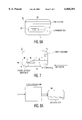
For ease of discussion, the invention will be illustrated using cards, such as debit cards (or cash value cards) which are issued to individuals in payment of a certain sum of money. These debit cards are also referred to as cash value cards or cash cards since they may be redeemed for cash or the equivalent in goods and/or services. In fact, a card holder uses the card when making withdrawals at a money dispensing or card acceptance machine. By way of example, as shown in FIG. 8A, a person may insert cash ($) into a card vending machine 95 and the card vending machine will issue a debit or cash value card 100. Subsequently, as shown in FIG. 8B, the purchaser of the card can insert the card 100 into a cash dispensing (card accepting) machine 97 to withdraw all or part of the cash value of the card 100.
In one application, each time the card holder makes a withdrawal, a hole is punched through the card to indicate the amount of the withdrawal. For example, assume that a card issued for payment of $2,000.00 has a value of $2,000.00 and that the $2000.00 card is arranged to have 20 units with each unit representing a value of $100.00. A card holder may then make partial cash withdrawals (receive payment) in units of $100.00, or the card holder may receive goods (e.g., tokens, chips, balls) or services meted out in units of $100.00. For each unit (e.g., $100.00) withdrawn, a hole is punched in the card to indicate that the value of the card has been decreased by one unit (e.g., $100.00). If a card has a value of 20 units, there can be a maximum of 20 unit holes punched in the card to indicate that the entire value of the card has been used up.
By way of example, a card 100 is shown in FIG. 1. The card has a strip 102 along which holes may be punched. Typically, as shown in FIG. 1, an issuance hole 1A is punched into the card by the card vending machine 95 at the time of the issuance of the card so as to validate the card. Subsequently, 20 additional holes (2-21) may be punched into the card by the cash dispensing machine 97 each time a withdrawal is made. Hole number 2 is punched into the card after the first unit value is used up (e.g., $100.00 is withdrawn). Subsequently, hole number 3 is punched into the card after the second unit value is used up (e.g., another $100.00 is withdrawn), and so on. Thus, if the card holder used up the 20 units of value on the card by making 20 individual withdrawals, there would be a hole at each of twenty positions, plus an additional card issuance hole for a total of twenty one holes. In some prior art applications, if the card purchaser used up two units at a single transaction, there would be a single hole at the two unit position. Likewise, if the card used up twenty units in a single transaction, there would be a single hole at the 20 unit position. In any event, in accordance with the prior art, one or more holes are punched into a cash card until all the holes are punched or until the last hole (unit 20) is punched.
A problem with the above scheme is that it is possible to falsify the value of the card by simply filling in the holes of the cards using an opaque material. After the holes in the card have been filled up, the counterfeiter (thief) can reuse the card as if it were new and make cash (or the equivalent) withdrawals for the full value of the underlying card. The counterfeiter can then reuse the card an indefinite number of times.
It is known to deter the efforts of a counterfeiter (or falsifier) by manufacturing the cash cards 100 with a hologram stripe 101 on which is formed a holographic type of image in the same plane as the one in which the holes are to be punched, as shown in FIG. 2. For such cards, the holes simply cannot be filled up by conventional methods to fool a dispensing machine. If there is a hole in the holographic image, it becomes very difficult, if not impossible, for a counterfeiter to fill up the hologram image without using some very expensive methods. Nevertheless, it is still possible for a counterfeiter to reuse a canceled card by cutting off a portion of the top of the hologram stripe (e.g., section 101A) above the holes; and then pasting the portion of the hologram stripe (101A) on the portion (101B) of a previously canceled card so that the holes are covered. Alternatively, a counterfeiter may produce a false hologram to place over a strip 101 even though its placement in an appropriate manner so as to fool a dispensing machine presents a significant problem. In either method, the counterfeiting process is then normally completed by punching an issuance hole in the first position (i.e., the card issuance position).
An object of the invention is to make the falsification of the value of a cash card or the counterfeiting of such cards extremely difficult, if not impossible.
As noted above, the cash card is an example of a particular application of the invention. It is an object of the invention to impede the counterfeiting and/or falsification of any valuable instrument/card/document. Therefore, note that in the discussion to follow and in the appended claims, when the term "instrument" is used without limitation, it is intended that the term "card" or "document" be included and vice-versa.
SUMMARY OF THE INVENTION
In systems embodying the invention, a card, instrument or document is encoded with first and second marks with the distance between the first mark and the second mark being programmable, such that the distance between the first mark and the second mark may be different for different cards (instruments or documents). The first mark may be a reference mark and the second mark may be an issuance mark. In the discussion to follow, the issuance mark used in the embodiments is an "issuance hole". However, it should be understood that, in practicing the invention, any suitable "issuance mark" may be used instead of an issuance hole.
In some embodiments, the location of the issuance hole may be selected to be placed anywhere on a card. In other embodiments, the location of the issuance hole may be any one of "N" possible hole locations located along a row or strip of a card; where N may be any integer greater than one.
The reference mark may be any number of different indicia and may be formed such that different points, or parts, of the reference mark may be used as the reference point to measure the distance to the issuance hole.
In certain embodiments, the reference mark is a hologram. In other embodiments, the reference mark is a bar code image (which may be visible or invisible to the naked eye). In still other embodiments, the reference mark may be a graphic image. In still other embodiments, the reference mark may be a "reference" hole.
In certain embodiments of the invention, the cash cards include a magnetic strip on which is written encoded information pertaining to the relationship between the reference mark and the issuance hole.
In systems embodying the invention a card vending machine may be programmed to locate (or form) a reference mark on a card and to form an issuance mark on the card at different distances relative to the reference mark. The information relating to the distance is encoded (encrypted) and stored in an information storage medium (e.g., a magnetic stripe) located on the card.
Subsequently, a user may use the card containing the reference and issuance marks to obtain either cash, goods or services from a dispensing machine programmed to read and decode the information stored in the storage medium.
BRIEF DESCRIPTION OF THE DRAWINGS
In the accompanying drawings, like reference characters denote like components, and
FIG. 1 illustrates one side of a cash (value) card;
FIG. 2 shows the one side of a cash card with a hologram stripe and a row of punched holes;
FIG. 3 shows the one side of a cash card with a holographic image formed within the hologram stripe;
FIG. 4 illustrates one side of a cash card with a reference mark used to define the location of an issuance hole;
FIG. 5 illustrates one side of a cash card with a bar code used to define the location of an issuance hole;
FIG. 6 illustrates one side of a cash card on which is formed a holostripe on top of a magnetic stripe;
FIG. 6A illustrates the use of different storage mediums on a card;
FIG. 7 illustrates one side of a cash card and different points which may be used to locate the issuance hole;
FIG. 8A is a very basic block diagram of a card vending (card producing) machine;
FIG. 8B is a very basic block diagram of a cash dispensing (card accepting) machine;
FIG. 9A is a simplified block diagram of a portion of a card vending machine modified in accordance with the invention; and
FIG. 9B is a simplified block diagram of a portion of a vending machine modified in accordance with the invention.
DESCRIPTION OF THE INVENTION
In order to counter attempts to counterfeit or falsify the value of a debit card (cash card), applicants developed a system to render attempts to counterfeit or falsify the debit cards extremely difficult and/or inordinately expensive, if not impossible.
In order to produce cards in accordance with the invention, the prior art vending machine may be modified as shown in FIG. 9A. Thus, in FIG. 9A, a "blank" card (a card to be annotated) 100a is propagated along a motorized carriage 190 through the machine 95A. The machine includes a microcontroller 191 which supplies critical signals to a reference image (mark) generator 192, an issuance mark generator 193 and a data encoder and writer 194. Under the control of controller 191, the reference mark generator 192 places a reference mark, whose shape may also be controlled and programmably altered, onto the card. The issuance mark generator 193 then places an issuance mark on the card of a shape and at a location programmably controlled by controller 191. The distance "d" between the reference mark, or an arbitrary point on the reference mark, and the issuance mark is then determined by the controller 191. The controller 191 includes, in combination with a data encoder and writer 194, means for encoding the data and then writing the encoded information onto the card.
In accordance with the invention, the controller 191 may be programmed to vary the shape and location of the reference mark. Likewise, the controller 191 may be programmed to vary the location of the issuance mark relative to the reference mark. The spacing (distance) between the reference and issuance marks may be sensed by the distance programmer 195 coupled to the controller 191 which then decodes the information and supplies it to data writer 194. The controller may also be programmed to vary the shape of the reference mark to further increase the difficulty of counterfeiting the mark. The reference and/or issuance marks may be: holes punched in the card; graphic symbols engraved or burned into the card; holographic images; or any other indicia which is machine readable or which may be rendered machine readable.
In order to read or sense the cards embodying the invention, the dispensing (card accepting) machine may be modified as shown in FIG. 9B. As shown in FIG. 9B, the dispensing machine 97A includes a sensor 201 to sense the reference mark location, a sensor 202 to sense the location of the issuance mark and a data reader (decoder) 203. Sensors 201 and 202, and reader/decoder 203 are coupled to a controller/checker 204. Typically, when a card is inserted into dispenser 97A, the reader/decoder 203 reads (senses) the stored information written in a magnetic strip (or other storage medium) located on the card. This information is decoded and the controller 204 is provided with the information about the shapes of the reference and issuance marks and the distance between these marks. The reference mark sensor 201 senses information regarding the location and shape of the reference mark which it senses and feeds this information to the controller. Likewise, the issuance mark sensor 202 senses information regarding the location and shape of the issuance mark which it sees and feeds this information to the controller 204. The controller 204 evaluates the information received from sensors 201, 202 and 203 and compares the received information to the information received from reader/decoder 203. If the information matches, controller/checker 204 signals the dispenser to issue cash, goods or services. If the information does not match, controller/checker 204 will send an alarm indicative of the presence of a false card.
In accordance with one embodiment of the invention, the location of the issuance hole is programmed to be placed in any one of N predetermined positions on a card such as shown in FIGS. 1 and 2, where the N holes will be punched along the strip 102 or 101 and N is any integer greater than one. For example, there may be 20 possible locations for punching cancellation holes in the card and one location for punching the card issuance hole. That is, in accordance with the invention, a card vending machine such as 95A in FIG. 9A may be programmed to locate the issuance hole in any one of 21 possible positions. The location of the issuance hole is then encoded (encrypted) by the vending machine and then written (stored) by the machine onto a magnetic stripe (see FIG. 6) or any suitable storage medium located on the card, as shown, for example, in FIG. 6A discussed below. Therefore, for the example of a card with 20 possible hole locations and one issuance hole location, the card issuance hole may be located in any one of twenty one positions. This reduces the odds of a counterfeiter getting the issuance hole in the correct position to 1 in 21.
In accordance with another embodiment of the invention, in the manufacturing of the debit cards, there is a holostripe placed on the cards as shown in FIG. 2. Contained within this holostripe is an image that is detectable by machine readable means. Since the cards are made on a mass production basis, it is difficult for the card manufacturer to accurately register the edge of the holostripe to the card edge. An aspect of the present invention is to use the inherent randomness of the manufacturing process in which the holostripe is randomly placed on the card to effectively deter any attempts to counterfeit the card. Since the holographic image located in the holostripe has a finite size and a definite start of image characteristic, the random location of the hologram image is used to calculate and to then store on the card the information pertaining to the location of the card issuance hole.
FIG. 3 shows a holographic image (holoimage) 111 and an issuance hole 1A located a distance "d" from the back edge 113 of holoimage 111. At the time the card is issued to a purchaser, it is passed through a vending machine 95A, as shown in FIG. 9A, which includes a motorized carriage for moving the card through a reader (or like sensor) at a constant speed. During this operation, the vending machine 95A, modified in accordance with the invention, includes sensing and logic circuitry and the appropriate software to very accurately calculate the distance "d" between the beginning (or some other predetermined point) of the holographic image 111 and the location where the issuance hole is punched (which can be located in any one of N, e.g., 21, positions). The distance measurement is then written (encoded) together with additional information onto the magnetic stripe (or any other suitable storage medium) located on the card for future verification. If the counterfeiter cuts a stripe from an existing card and attempts to cover the existing holes on a previously canceled card, it will be impossible for the counterfeiter to exactly duplicate the holoimage position. If the new stripe is positioned such that the issuance hole of the "falsified" card is at a distance other than "d" from the selected point on the reference mark, the accurate measurement calculations between the image 111 and the issuance hole 1A will not match the condition set by the vending machine issuing the card. In addition, where the issuance hole is algorithmically defined to be one of N (e.g., 21 or more) locations, it is very difficult to identify which hole is the issuance hole.
In still another embodiment of the invention, as shown in FIG. 4, the issuance hole 1A is located at a distance "d" from a random indicator mark 140, which may be a hole punched into the card or any other suitable marker or indicia. Mark 140 is a reference mark which may be a randomly placed mark or a random indicator mark, in that it may be place at virtually any selected (random) location on the card. In this instance, no reliance is made on the holographic image 111 or stripe to locate the issuance hole 1A.
In systems embodying the invention, information pertaining to the distance "d" between a reference mark and an issuance mark is stored in a storage medium located on the card, as shown, for example, in FIGS. 6 and 6A. Also, any pertinent parameters and information regarding the reference mark and/or the issuance mark may be stored in the information storage medium. In FIG. 6, the information storage medium is a magnetic stripe. As shown in FIG. 6, cards embodying the invention may include a holostripe 101 containing a holoimage 111 and a magnetic stripe 121. The magnetic stripe may be formed immediately below the holostripe or it may be formed adjacent to the holostripe, on the same side of the card, or the magnetic stripe may be formed on the side of the card opposite to the side on which the holostripe is formed. In FIG. 6A, the storage medium is a thin film 122 on which may be formed semiconductor devices to electronically store information. Another information storage medium, shown in FIG. 6A, is a strip 123 on which may be printed an alphanumeric code. It should be noted that the dispensing machines 97A will include reading systems capable of reading the information stored in the cards.
As part of the system to make the cards more secure (i.e., more difficult to falsify or counterfeit) information is encoded (written in code) on the magnetic stripe. For example, when one card is issued from vending machine 95A, the distance "d" in FIGS. 3, 4 or 5 may have a first value (e.g., 0.5 inches) for one card. This value (information) is encrypted in the magnetic stripe of that card. When another card is issued by the card dispensing machine, the distance "d" in FIGS. 3, 4 and 5 may have a second value (e.g., 0.6 inches). By varying the distance "d", the location of the issuance hole has been "randomized". Furthermore, its location on the card can only be determined by ascertaining which "indicium" or "marker" the issuance hole is referenced to. In FIG. 3, the issuance hole is referenced to some point associated with holographic image 111. That point, for example, may be the beginning or the end or some intermediate bar of holographic image 111.
In FIG. 4, the random mark 140 may be, for example, a hole or an image of some animal or fruit. If an animal, such as a horse with 4 legs is used, the distance "d" may be referenced to any one of the 4 legs of the horse or to any other suitable point on the animal.
Likewise, in FIG. 5, the issuance hole is referenced to a bar code image 150. The location of the issuance hole may be located at a distance "d" relative to any one of a number of different bars of the bar code. The distance "d" may vary and the bar or space on the bar code being used as a reference may vary. Thus, a counterfeiter or falsifier of a card must be able to solve these additional problems in order to reuse a canceled card (or a partially used card) or to produce another card which when inserted into a dispensing machine 95B will be recognized as a valid card.
Applicants' invention is also applicable to instances where a counterfeiter becomes able to "exactly" duplicate debit cards. This can conceivably occur where a counterfeiter stole a debit card vending machine. Such machine would include a "correct" or valid hole punching algorithm. Accordingly, the cards dispensed from a stolen vending machine would contain the correct hole punching algorithms and would pass the security system outline. To counter this problem, each vending machine 95A may be manufactured with a unique electronic serial number. That serial number will be written to the storage medium (e.g., magnetic portion) of the card. However, once the theft of the "valid" machine is detected, the serial number of a stolen machine can then be electronically downloaded to all of the cash dispensing machines. The cash dispensing machines will then cross-check the vending serial number against the downloaded information to prevent pay out on a "counterfeit" card.
FIG. 7 is designed to illustrate that the distance measurements from the issuance hole 1A may be referenced to either one of the following points:
(a) the front edge of the card 116 (distances d3+d2+d4); or
(b) the front edge 112 of the holographic image 111 (distances d3+d2); or
(c) the back edge 113 of the holographic image 111 (distance d3); or
(d) any intermediate point along the hologram; or
(e) the randomly placed mark or hole 140 (distance d1); or
(f) any permutation or combination of distances d1, d2, d3 and d4.
The card vending machine 95A is programmed to determine which one of the measurements (or the combination of measurements), shown in FIG. 7, are used to define the issuance hole and the reference mark. The card vending machine is also programmed to code the information and to generate a cryptogram containing the information. The encrypted (encoded) information is then written into and/or onto the magnetic stripe (or any other storage medium located on the card) and the issuance hole is punched on the card.
Card vending machine 95A includes a carriage driven by a motor to advance the card along a path. The gear rotation of the motor may be used to determine the distances between the reference and the issuance marks. Alternatively, vending machine 95A may include an electronic timer (not shown) or any other suitable system which can be used to determine the various distances.
Cards, which may be of the plastic type in common use, have been used by way of example to illustrate the application of the invention. It should be appreciated that the invention may be used with other materials such as specially treated paper (similar to travelers checks or any like negotiable instrument) or any document (e.g., a passport). Therefore, in the appended claims reference to an instrument is intended to mean any item of manufacture or any document (e.g., a passport) suitable for the placing thereon of a (e.g., first) reference mark and an issuance (e.g., second) mark in accordance with the invention.
As noted above the issuance hole is used by way of example and any "issuance mark" may be used. That is, the issuance mark may be formed by a laser beam or by a heating element or by any other suitable means to indicate, or form, an issuance mark (e.g., second mark) at a programmable distance from a reference mark (e.g., first mark) and which "issuance mark" can be read or sensed by a suitable electronic or electro-optic sensor.
Regarding the reference mark, a "blank" card may come formed or prepared with a reference mark, in which case, the "vending" machine would first identify its location before forming an issuance mark. Alternatively, if a blank card does not contain a reference mark, the vending machine will form and locate a reference mark by using the reference mark generator as discussed above.
The invention has been illustrated using a "reference mark" and an "issuance" mark. However, it should be appreciated that any "first" and "second" marks may be used.

Claims (25)

What is claimed is:
1. An instrument comprising:
a first mark located on the surface of said instrument; wherein said first mark is a reference hole punched into said instrument;
a second mark formed on said instrument at a programmably selected distance "d" from said first mark, said second mark being located at any one of a plurality of different possible locations on the surface area of said instrument; and
an information storage medium located on said instrument for storing encoded information pertaining to the distance "d" between said first and second marks.
2. An instrument as claimed in claim 1 wherein said information storage medium is a magnetic stripe.
3. An instrument as claimed in claim 1 wherein said information storage medium is an electronic storage device.
4. An instrument as claimed in claim 1 wherein said information storage medium includes encoded data printed on said instrument.
5. An instrument as claimed in claim 1 wherein at least one of said first and second marks is a holographic image.
6. An instrument as claimed in claim 1 wherein at least one of said first and second marks includes a machine readable image.
7. An instrument as claimed in claim 1 wherein at least one of said first and second marks includes a bar code.
8. An instrument as claimed in claim 7 wherein at least one of said first and second marks is invisible to the naked eye.
9. An instrument as claimed in claim 1 wherein said first mark is a reference mark and said second mark is an issuance mark.
10. The invention as claimed in claim 9 wherein said instrument is a card.
11. The invention as claimed in claim 10 wherein said card is a cash value card and wherein at least one of said reference and issuance marks is a hole punched into the card.
12. The invention as claimed in claim 10 wherein the information storage medium located on said card is a magnetic stripe.
13. A card including:
a reference mark located on said card; wherein said reference mark includes a reference hole punched in said card;
an issuance mark located on said card at a programmably selected distance "d" from said reference mark, said reference mark and said issuance mark being located at any of a plurality of different possible locations present on and within the surface area of said card; and
an information storage medium located on said card for storing encoded information pertaining to the distance "d" between said reference and issuance marks.
14. A card as claimed in claim 13 wherein said information storage medium is a magnetic stripe.
15. A card as claimed in claim 13 wherein at least one of said reference and issuance marks is a holographic image.
16. A card as claimed in claim 13 wherein at least one of said reference and issuance marks is a bar code.
17. A card as claimed in claim 13 wherein said bar code is invisible to the naked eye.
18. A card as claimed in claim 13 wherein said reference and issuance marks are machine readable.
19. An instrument as claimed in claim 1, wherein said first mark is randomly located at any selected location on the surface of said instrument; wherein said instrument includes a plurality of defined locations; and wherein said second mark may be selected to be located at any one of said plurality of locations.
20. An instrument as claimed in claim 19, wherein said first mark is a reference mark, wherein said second mark is an issuance mark, and wherein the remaining defined locations indicate a designated value of the instrument.
21. An instrument as claimed in claim 20, wherein said second mark is a issuance hole punched in said instrument.
22. An instrument as claimed in claim 1 wherein said instrument includes a plurality of defined locations and wherein said first mark may be any one of said plurality of locations and said second mark may be any other one of said plurality of locations.
23. An instrument as claimed in claim 1 wherein said storage medium includes semiconductor devices for electronically storing information.
24. An instrument as claimed in claim 1, wherein said information storage medium also stores information pertaining to the location of the first and second marks.
25. A card as claimed in claim 13 wherein said issuance mark is an issuance hole.
US09/084,844 1998-05-26 1998-05-26 Method and apparatus for impeding the counterfeiting of cards, instruments and documents Expired - Fee Related US6068301A (en)

Priority Applications (8)

Application Number Priority Date Filing Date Title
US09/084,844 US6068301A (en) 1998-05-26 1998-05-26 Method and apparatus for impeding the counterfeiting of cards, instruments and documents
US09/300,969 US6354506B1 (en) 1998-05-26 1999-04-28 Method and apparatus for impeding the counterfeiting of cards, instruments and documents
AU42036/99A AU4203699A (en) 1998-05-26 1999-05-25 Method and apparatus for impeding the counterfeiting of cards, instruments and documents
CA002297830A CA2297830A1 (en) 1998-05-26 1999-05-25 Method and apparatus for impeding the counterfeiting of cards, instruments and documents
PCT/US1999/011524 WO1999062027A1 (en) 1998-05-26 1999-05-25 Method and apparatus for impeding the counterfeiting of cards, instruments and documents
EP99925823A EP1010135A1 (en) 1998-05-26 1999-05-25 Method and apparatus for impeding the counterfeiting of cards, instruments and documents
JP2000551357A JP2002517046A (en) 1998-05-26 1999-05-25 Method and apparatus for eliminating imitation of cards, instruments and documents
US09/434,959 US6135355A (en) 1998-05-26 1999-11-05 Method and apparatus for impeding the counterfeiting of cards, instruments and documents

Applications Claiming Priority (1)

Application Number Priority Date Filing Date Title
US09/084,844 US6068301A (en) 1998-05-26 1998-05-26 Method and apparatus for impeding the counterfeiting of cards, instruments and documents

Related Child Applications (2)

Application Number Title Priority Date Filing Date
US09/300,969 Division US6354506B1 (en) 1998-05-26 1999-04-28 Method and apparatus for impeding the counterfeiting of cards, instruments and documents
US09/434,959 Division US6135355A (en) 1998-05-26 1999-11-05 Method and apparatus for impeding the counterfeiting of cards, instruments and documents

Publications (1)

Publication Number Publication Date
US6068301A true US6068301A (en) 2000-05-30

Family

ID=22187577

Family Applications (3)

Application Number Title Priority Date Filing Date
US09/084,844 Expired - Fee Related US6068301A (en) 1998-05-26 1998-05-26 Method and apparatus for impeding the counterfeiting of cards, instruments and documents
US09/300,969 Expired - Fee Related US6354506B1 (en) 1998-05-26 1999-04-28 Method and apparatus for impeding the counterfeiting of cards, instruments and documents
US09/434,959 Expired - Fee Related US6135355A (en) 1998-05-26 1999-11-05 Method and apparatus for impeding the counterfeiting of cards, instruments and documents

Family Applications After (2)

Application Number Title Priority Date Filing Date
US09/300,969 Expired - Fee Related US6354506B1 (en) 1998-05-26 1999-04-28 Method and apparatus for impeding the counterfeiting of cards, instruments and documents
US09/434,959 Expired - Fee Related US6135355A (en) 1998-05-26 1999-11-05 Method and apparatus for impeding the counterfeiting of cards, instruments and documents

Country Status (6)

Country Link
US (3) US6068301A (en)
EP (1) EP1010135A1 (en)
JP (1) JP2002517046A (en)
AU (1) AU4203699A (en)
CA (1) CA2297830A1 (en)
WO (1) WO1999062027A1 (en)

Cited By (9)

* Cited by examiner, † Cited by third party
Publication number Priority date Publication date Assignee Title
US6199761B1 (en) * 1996-12-09 2001-03-13 Drexler Technology Corporation Validation method for electronic cash cards and digital identity cards utilizing optical data storage
US6491324B1 (en) * 1997-07-24 2002-12-10 Giesecke & Devrient Gmbh Safety document
US20080041955A1 (en) * 2006-03-22 2008-02-21 Stephan Volkening Method and Device For Reading Information Optically
US20090007258A1 (en) * 2006-01-06 2009-01-01 Verichk Global Technologies Inc. Secure Access to Information Associated With a Value Item
US20100155463A1 (en) * 2008-12-22 2010-06-24 Roquemore Iii John P Fraudulent document detection system and method
USD635186S1 (en) * 2008-06-30 2011-03-29 Jpmorgan Chase Bank, N.A. Metal transaction device
USD636021S1 (en) 2008-07-17 2011-04-12 Jpmorgan Chase Bank, N.A. Eco-friendly transaction device
US8020754B2 (en) 2001-08-13 2011-09-20 Jpmorgan Chase Bank, N.A. System and method for funding a collective account by use of an electronic tag
US20160092761A1 (en) * 2013-05-13 2016-03-31 Skimprot, Limited Liability Company Protective stripe for bank cards

Families Citing this family (21)

* Cited by examiner, † Cited by third party
Publication number Priority date Publication date Assignee Title
NL1008097C2 (en) * 1998-01-22 1999-07-26 Unicate Software Management N Method and system for identifying one or more objects.
US6321981B1 (en) * 1998-12-22 2001-11-27 Eastman Kodak Company Method and apparatus for transaction card security utilizing embedded image data
JP3733268B2 (en) * 1999-10-26 2006-01-11 キヤノン株式会社 Image processing apparatus and method, and storage medium
EP1136960A1 (en) 2000-03-24 2001-09-26 Infineon Technologies AG Individual arrangement
US7025265B2 (en) * 2001-04-10 2006-04-11 Excel Precision Corp. Information card system
US7028884B2 (en) * 2001-11-22 2006-04-18 Leif Nyfelt Method of verifying ID-papers and the like
US20040267622A1 (en) * 2002-01-10 2004-12-30 Taylor John David Taylor corp.pre-paid cash cards unlimited
US7708189B1 (en) 2002-05-17 2010-05-04 Cipriano Joseph J Identification verification system and method
US8171567B1 (en) 2002-09-04 2012-05-01 Tracer Detection Technology Corp. Authentication method and system
GB0402025D0 (en) * 2004-01-30 2004-03-03 Hewlett Packard Development Co Physical object with memory tag and apparatus for use with such objects
US8943325B2 (en) * 2004-02-06 2015-01-27 Signoptic Technologies Savoie Technolac Use of a digital signature obtained from at least one structural characteristic of a material element to protect the direct reading of sensitive data and method for reading this protected data
FR2870376B1 (en) * 2004-05-11 2006-09-22 Yann Boutant METHOD FOR RECOGNIZING FIBROUS MEDIA, AND APPLICATIONS OF SUCH A METHOD IN THE COMPUTER FIELD, IN PARTICULAR
US7860318B2 (en) 2004-11-09 2010-12-28 Intelli-Check, Inc System and method for comparing documents
US7648076B2 (en) * 2005-11-21 2010-01-19 Jds Uniphase Corporation Magnetic tape with holographic hidden pattern, method of making same and reader for reading same
CN101479750A (en) * 2006-05-11 2009-07-08 奇异编号有限公司 Method of identifying an object, an identification tag, an object adapted to be identified, and related device and system
AT504658B1 (en) * 2007-01-26 2008-07-15 Czak Christian Dkfm SECURING OBJECT
KR20100009952A (en) * 2008-07-21 2010-01-29 삼성에스디아이 주식회사 Method for driving plasma display panel, and plasma display apparatus adopting the method
CH699477A1 (en) * 2008-08-29 2010-03-15 Unica Technology Ag Identification feature.
TWI622969B (en) 2012-12-17 2018-05-01 印奈克斯托股份有限公司 Method and apparatus for marking manufactured items using physical characteristic
US10373409B2 (en) 2014-10-31 2019-08-06 Intellicheck, Inc. Identification scan in compliance with jurisdictional or other rules
EP3293680A1 (en) * 2016-09-12 2018-03-14 Authentic Vision GmbH Sheet-like product and method for authenticating a security tag

Citations (6)

* Cited by examiner, † Cited by third party
Publication number Priority date Publication date Assignee Title
US3676644A (en) * 1970-03-05 1972-07-11 Columbia Controls Research Cor Coded document and system for automatically reading same
US4507550A (en) * 1983-05-13 1985-03-26 Umc Industries, Inc. High security credit card, system and method
US4621188A (en) * 1983-10-05 1986-11-04 Stockburger H Data card and data strip measuring means
US4630845A (en) * 1983-08-25 1986-12-23 Light Signatures, Inc. Authentication document system
US5319476A (en) * 1992-01-10 1994-06-07 Dai Nippon Printing Co., Ltd. Multiply recorded hologram for security
US5559885A (en) * 1994-01-14 1996-09-24 Drexler Technology Corporation Two stage read-write method for transaction cards

Family Cites Families (15)

* Cited by examiner, † Cited by third party
Publication number Priority date Publication date Assignee Title
US4013894A (en) * 1975-05-27 1977-03-22 Addressograph Multigraph Corporation Secure property document and system
US4025759A (en) * 1975-10-16 1977-05-24 The Grey Lab. Establishment Checking apparatus for documents
US4141044A (en) * 1976-09-17 1979-02-20 The Mosler Safe Company Magnetically encoded card read/write/capture apparatus
US4675669A (en) * 1980-06-23 1987-06-23 Light Signatures, Inc. System of issuing secure documents of various denomination
DE3038614A1 (en) * 1980-10-13 1982-04-22 Copytex-Abrechnungssysteme für Dienstleistungsautomaten GbmH, 7742 St Georgen METHOD FOR RETURNING RETURN OF INFORMATION ENTERING ON A DATA CARRIER AND DEVICE FOR READING IN AND / OR READING OUT INFORMATION PROTECTED AGAINST RETURN TRANSFER
US4745267A (en) * 1983-12-28 1988-05-17 Fairview Partners Fraudulent card intercept system
JPH0636266B2 (en) * 1985-10-18 1994-05-11 キヤノン株式会社 Information recording / reproducing device
GB2183875B (en) * 1985-12-05 1990-02-21 Burroughs Corp Card reading apparatus
JPS63187384A (en) * 1987-01-30 1988-08-02 Canon Inc Data collator
JPH01190482A (en) * 1988-01-25 1989-07-31 Material Eng Tech Lab Inc Seal
NL9001368A (en) * 1990-06-15 1992-01-02 Tel Developments B V SECURITY OF OBJECTS OR DOCUMENTS.
US5491326A (en) * 1994-11-23 1996-02-13 Xcp, Inc. Card metering system
JP2950190B2 (en) * 1995-03-28 1999-09-20 株式会社田村電機製作所 Card issuing device
GB2309568B (en) * 1996-01-25 1999-09-29 Central Research Lab Ltd Method of identifying a data carrier
US5770846A (en) * 1996-02-15 1998-06-23 Mos; Robert Method and apparatus for securing and authenticating encoded data and documents containing such data

Patent Citations (6)

* Cited by examiner, † Cited by third party
Publication number Priority date Publication date Assignee Title
US3676644A (en) * 1970-03-05 1972-07-11 Columbia Controls Research Cor Coded document and system for automatically reading same
US4507550A (en) * 1983-05-13 1985-03-26 Umc Industries, Inc. High security credit card, system and method
US4630845A (en) * 1983-08-25 1986-12-23 Light Signatures, Inc. Authentication document system
US4621188A (en) * 1983-10-05 1986-11-04 Stockburger H Data card and data strip measuring means
US5319476A (en) * 1992-01-10 1994-06-07 Dai Nippon Printing Co., Ltd. Multiply recorded hologram for security
US5559885A (en) * 1994-01-14 1996-09-24 Drexler Technology Corporation Two stage read-write method for transaction cards

Cited By (14)

* Cited by examiner, † Cited by third party
Publication number Priority date Publication date Assignee Title
US6199761B1 (en) * 1996-12-09 2001-03-13 Drexler Technology Corporation Validation method for electronic cash cards and digital identity cards utilizing optical data storage
US6491324B1 (en) * 1997-07-24 2002-12-10 Giesecke & Devrient Gmbh Safety document
US8020754B2 (en) 2001-08-13 2011-09-20 Jpmorgan Chase Bank, N.A. System and method for funding a collective account by use of an electronic tag
US20090007258A1 (en) * 2006-01-06 2009-01-01 Verichk Global Technologies Inc. Secure Access to Information Associated With a Value Item
US9397837B2 (en) * 2006-01-06 2016-07-19 Sicpa Holding Sa Secure access to information associated with a value item
US8534557B2 (en) * 2006-03-22 2013-09-17 Bayer Innovation Gmbh Method and device for reading information optically
US20080041955A1 (en) * 2006-03-22 2008-02-21 Stephan Volkening Method and Device For Reading Information Optically
USD635186S1 (en) * 2008-06-30 2011-03-29 Jpmorgan Chase Bank, N.A. Metal transaction device
USD643062S1 (en) 2008-06-30 2011-08-09 Jpmorgan Chase Bank, N.A. Metal transaction device
USD636021S1 (en) 2008-07-17 2011-04-12 Jpmorgan Chase Bank, N.A. Eco-friendly transaction device
US8317085B2 (en) * 2008-12-22 2012-11-27 Ncr Corporation Fraudulent document detection system and method
US20100155463A1 (en) * 2008-12-22 2010-06-24 Roquemore Iii John P Fraudulent document detection system and method
US20160092761A1 (en) * 2013-05-13 2016-03-31 Skimprot, Limited Liability Company Protective stripe for bank cards
US9524455B2 (en) * 2013-05-13 2016-12-20 Skimport Protective stripe for bank cards

Also Published As

Publication number Publication date
JP2002517046A (en) 2002-06-11
CA2297830A1 (en) 1999-12-02
AU4203699A (en) 1999-12-13
US6354506B1 (en) 2002-03-12
WO1999062027A1 (en) 1999-12-02
US6135355A (en) 2000-10-24
EP1010135A1 (en) 2000-06-21

Similar Documents

Publication Publication Date Title
US6068301A (en) Method and apparatus for impeding the counterfeiting of cards, instruments and documents
US4745267A (en) Fraudulent card intercept system
US5790662A (en) Data carrier and write/read device therefor
EP0644508B1 (en) Secure optical identification method and means
WO1992016913A1 (en) Securing financial transactions
EP0152703A2 (en) Fraudulent card intercept system
US6560017B1 (en) Compound secure optical identification method and means
WO1995010905A1 (en) Apparatus for dispensing money orders
CA2197070A1 (en) Credit document connected to a document or customised card, independent customised credit card and associated issuance and validation equipment
US3774743A (en) Changeable verification check controlled vending
US7766245B2 (en) Virtual code window
EP1316923A2 (en) Media dispensing
JPH0776981B2 (en) Card-type recording medium recording / reproducing apparatus and method for preventing unauthorized use thereof
ES2321374T3 (en) PROCEDURE OF MARKING AND AUTHENTICATION OF AN OBJECT.
GB1410723A (en) System for automatically dispensing money or the like
JPH068077B2 (en) Card and card authenticity determination method
EP0660959A1 (en) Diffraction surface data detector
JPH01188397A (en) Recording medium
JPH01249495A (en) Card
US7617986B2 (en) Laminate security feature
JP3624714B2 (en) Underage identification device for vending machines
KR200302633Y1 (en) Magnetic stripe lottery ticket for lottery ticket vending machine
JPS6379168A (en) Controller for magnetic card reader
JPH0747792A (en) Card and method of determining genuieness and spuriousness of card
GB2407424A (en) Marking of articles

Legal Events

Date Code Title Description
REMI Maintenance fee reminder mailed
REIN Reinstatement after maintenance fee payment confirmed
FP Lapsed due to failure to pay maintenance fee

Effective date: 20040530

FEPP Fee payment procedure

Free format text: PETITION RELATED TO MAINTENANCE FEES FILED (ORIGINAL EVENT CODE: PMFP); ENTITY STATUS OF PATENT OWNER: SMALL ENTITY

FEPP Fee payment procedure

Free format text: PETITION RELATED TO MAINTENANCE FEES GRANTED (ORIGINAL EVENT CODE: PMFG); ENTITY STATUS OF PATENT OWNER: SMALL ENTITY

FPAY Fee payment

Year of fee payment: 4

SULP Surcharge for late payment
PRDP Patent reinstated due to the acceptance of a late maintenance fee

Effective date: 20050921

FPAY Fee payment

Year of fee payment: 8

REMI Maintenance fee reminder mailed
LAPS Lapse for failure to pay maintenance fees
STCH Information on status: patent discontinuation

Free format text: PATENT EXPIRED DUE TO NONPAYMENT OF MAINTENANCE FEES UNDER 37 CFR 1.362

FP Lapsed due to failure to pay maintenance fee

Effective date: 20120530