US5937935A - Heat exchanger and method of making the same - Google Patents
Heat exchanger and method of making the same Download PDFInfo
- Publication number
- US5937935A US5937935A US08/992,324 US99232497A US5937935A US 5937935 A US5937935 A US 5937935A US 99232497 A US99232497 A US 99232497A US 5937935 A US5937935 A US 5937935A
- Authority
- US
- United States
- Prior art keywords
- folded
- links
- members
- deformable links
- heat exchanger
- Prior art date
- Legal status (The legal status is an assumption and is not a legal conclusion. Google has not performed a legal analysis and makes no representation as to the accuracy of the status listed.)
- Expired - Lifetime
Links
Images


Classifications
-
- F—MECHANICAL ENGINEERING; LIGHTING; HEATING; WEAPONS; BLASTING
- F28—HEAT EXCHANGE IN GENERAL
- F28F—DETAILS OF HEAT-EXCHANGE AND HEAT-TRANSFER APPARATUS, OF GENERAL APPLICATION
- F28F9/00—Casings; Header boxes; Auxiliary supports for elements; Auxiliary members within casings
- F28F9/001—Casings in the form of plate-like arrangements; Frames enclosing a heat exchange core
-
- B—PERFORMING OPERATIONS; TRANSPORTING
- B21—MECHANICAL METAL-WORKING WITHOUT ESSENTIALLY REMOVING MATERIAL; PUNCHING METAL
- B21D—WORKING OR PROCESSING OF SHEET METAL OR METAL TUBES, RODS OR PROFILES WITHOUT ESSENTIALLY REMOVING MATERIAL; PUNCHING METAL
- B21D53/00—Making other particular articles
- B21D53/02—Making other particular articles heat exchangers or parts thereof, e.g. radiators, condensers fins, headers
- B21D53/04—Making other particular articles heat exchangers or parts thereof, e.g. radiators, condensers fins, headers of sheet metal
-
- F—MECHANICAL ENGINEERING; LIGHTING; HEATING; WEAPONS; BLASTING
- F28—HEAT EXCHANGE IN GENERAL
- F28D—HEAT-EXCHANGE APPARATUS, NOT PROVIDED FOR IN ANOTHER SUBCLASS, IN WHICH THE HEAT-EXCHANGE MEDIA DO NOT COME INTO DIRECT CONTACT
- F28D1/00—Heat-exchange apparatus having stationary conduit assemblies for one heat-exchange medium only, the media being in contact with different sides of the conduit wall, in which the other heat-exchange medium is a large body of fluid, e.g. domestic or motor car radiators
- F28D1/02—Heat-exchange apparatus having stationary conduit assemblies for one heat-exchange medium only, the media being in contact with different sides of the conduit wall, in which the other heat-exchange medium is a large body of fluid, e.g. domestic or motor car radiators with heat-exchange conduits immersed in the body of fluid
- F28D1/03—Heat-exchange apparatus having stationary conduit assemblies for one heat-exchange medium only, the media being in contact with different sides of the conduit wall, in which the other heat-exchange medium is a large body of fluid, e.g. domestic or motor car radiators with heat-exchange conduits immersed in the body of fluid with plate-like or laminated conduits
- F28D1/0308—Heat-exchange apparatus having stationary conduit assemblies for one heat-exchange medium only, the media being in contact with different sides of the conduit wall, in which the other heat-exchange medium is a large body of fluid, e.g. domestic or motor car radiators with heat-exchange conduits immersed in the body of fluid with plate-like or laminated conduits the conduits being formed by paired plates touching each other
- F28D1/0325—Heat-exchange apparatus having stationary conduit assemblies for one heat-exchange medium only, the media being in contact with different sides of the conduit wall, in which the other heat-exchange medium is a large body of fluid, e.g. domestic or motor car radiators with heat-exchange conduits immersed in the body of fluid with plate-like or laminated conduits the conduits being formed by paired plates touching each other the plates having lateral openings therein for circulation of the heat-exchange medium from one conduit to another
- F28D1/0333—Heat-exchange apparatus having stationary conduit assemblies for one heat-exchange medium only, the media being in contact with different sides of the conduit wall, in which the other heat-exchange medium is a large body of fluid, e.g. domestic or motor car radiators with heat-exchange conduits immersed in the body of fluid with plate-like or laminated conduits the conduits being formed by paired plates touching each other the plates having lateral openings therein for circulation of the heat-exchange medium from one conduit to another the plates having integrated connecting members
-
- F—MECHANICAL ENGINEERING; LIGHTING; HEATING; WEAPONS; BLASTING
- F28—HEAT EXCHANGE IN GENERAL
- F28D—HEAT-EXCHANGE APPARATUS, NOT PROVIDED FOR IN ANOTHER SUBCLASS, IN WHICH THE HEAT-EXCHANGE MEDIA DO NOT COME INTO DIRECT CONTACT
- F28D1/00—Heat-exchange apparatus having stationary conduit assemblies for one heat-exchange medium only, the media being in contact with different sides of the conduit wall, in which the other heat-exchange medium is a large body of fluid, e.g. domestic or motor car radiators
- F28D1/02—Heat-exchange apparatus having stationary conduit assemblies for one heat-exchange medium only, the media being in contact with different sides of the conduit wall, in which the other heat-exchange medium is a large body of fluid, e.g. domestic or motor car radiators with heat-exchange conduits immersed in the body of fluid
- F28D1/03—Heat-exchange apparatus having stationary conduit assemblies for one heat-exchange medium only, the media being in contact with different sides of the conduit wall, in which the other heat-exchange medium is a large body of fluid, e.g. domestic or motor car radiators with heat-exchange conduits immersed in the body of fluid with plate-like or laminated conduits
- F28D1/0391—Heat-exchange apparatus having stationary conduit assemblies for one heat-exchange medium only, the media being in contact with different sides of the conduit wall, in which the other heat-exchange medium is a large body of fluid, e.g. domestic or motor car radiators with heat-exchange conduits immersed in the body of fluid with plate-like or laminated conduits a single plate being bent to form one or more conduits
-
- F—MECHANICAL ENGINEERING; LIGHTING; HEATING; WEAPONS; BLASTING
- F28—HEAT EXCHANGE IN GENERAL
- F28F—DETAILS OF HEAT-EXCHANGE AND HEAT-TRANSFER APPARATUS, OF GENERAL APPLICATION
- F28F3/00—Plate-like or laminated elements; Assemblies of plate-like or laminated elements
- F28F3/02—Elements or assemblies thereof with means for increasing heat-transfer area, e.g. with fins, with recesses, with corrugations
- F28F3/025—Elements or assemblies thereof with means for increasing heat-transfer area, e.g. with fins, with recesses, with corrugations the means being corrugated, plate-like elements
-
- F—MECHANICAL ENGINEERING; LIGHTING; HEATING; WEAPONS; BLASTING
- F28—HEAT EXCHANGE IN GENERAL
- F28F—DETAILS OF HEAT-EXCHANGE AND HEAT-TRANSFER APPARATUS, OF GENERAL APPLICATION
- F28F3/00—Plate-like or laminated elements; Assemblies of plate-like or laminated elements
- F28F3/02—Elements or assemblies thereof with means for increasing heat-transfer area, e.g. with fins, with recesses, with corrugations
- F28F3/04—Elements or assemblies thereof with means for increasing heat-transfer area, e.g. with fins, with recesses, with corrugations the means being integral with the element
- F28F3/042—Elements or assemblies thereof with means for increasing heat-transfer area, e.g. with fins, with recesses, with corrugations the means being integral with the element in the form of local deformations of the element
- F28F3/044—Elements or assemblies thereof with means for increasing heat-transfer area, e.g. with fins, with recesses, with corrugations the means being integral with the element in the form of local deformations of the element the deformations being pontual, e.g. dimples
-
- F—MECHANICAL ENGINEERING; LIGHTING; HEATING; WEAPONS; BLASTING
- F28—HEAT EXCHANGE IN GENERAL
- F28F—DETAILS OF HEAT-EXCHANGE AND HEAT-TRANSFER APPARATUS, OF GENERAL APPLICATION
- F28F3/00—Plate-like or laminated elements; Assemblies of plate-like or laminated elements
- F28F3/12—Elements constructed in the shape of a hollow panel, e.g. with channels
-
- F—MECHANICAL ENGINEERING; LIGHTING; HEATING; WEAPONS; BLASTING
- F28—HEAT EXCHANGE IN GENERAL
- F28F—DETAILS OF HEAT-EXCHANGE AND HEAT-TRANSFER APPARATUS, OF GENERAL APPLICATION
- F28F9/00—Casings; Header boxes; Auxiliary supports for elements; Auxiliary members within casings
- F28F9/02—Header boxes; End plates
- F28F9/0202—Header boxes having their inner space divided by partitions
- F28F9/0204—Header boxes having their inner space divided by partitions for elongated header box, e.g. with transversal and longitudinal partitions
- F28F9/0207—Header boxes having their inner space divided by partitions for elongated header box, e.g. with transversal and longitudinal partitions the longitudinal or transversal partitions being separate elements attached to header boxes
-
- F—MECHANICAL ENGINEERING; LIGHTING; HEATING; WEAPONS; BLASTING
- F28—HEAT EXCHANGE IN GENERAL
- F28F—DETAILS OF HEAT-EXCHANGE AND HEAT-TRANSFER APPARATUS, OF GENERAL APPLICATION
- F28F9/00—Casings; Header boxes; Auxiliary supports for elements; Auxiliary members within casings
- F28F9/22—Arrangements for directing heat-exchange media into successive compartments, e.g. arrangements of guide plates
- F28F2009/222—Particular guide plates, baffles or deflectors, e.g. having particular orientation relative to an elongated casing or conduit
-
- Y—GENERAL TAGGING OF NEW TECHNOLOGICAL DEVELOPMENTS; GENERAL TAGGING OF CROSS-SECTIONAL TECHNOLOGIES SPANNING OVER SEVERAL SECTIONS OF THE IPC; TECHNICAL SUBJECTS COVERED BY FORMER USPC CROSS-REFERENCE ART COLLECTIONS [XRACs] AND DIGESTS
- Y10—TECHNICAL SUBJECTS COVERED BY FORMER USPC
- Y10S—TECHNICAL SUBJECTS COVERED BY FORMER USPC CROSS-REFERENCE ART COLLECTIONS [XRACs] AND DIGESTS
- Y10S165/00—Heat exchange
- Y10S165/454—Heat exchange having side-by-side conduits structure or conduit section
- Y10S165/464—Conduits formed by joined pairs of matched plates
-
- Y—GENERAL TAGGING OF NEW TECHNOLOGICAL DEVELOPMENTS; GENERAL TAGGING OF CROSS-SECTIONAL TECHNOLOGIES SPANNING OVER SEVERAL SECTIONS OF THE IPC; TECHNICAL SUBJECTS COVERED BY FORMER USPC CROSS-REFERENCE ART COLLECTIONS [XRACs] AND DIGESTS
- Y10—TECHNICAL SUBJECTS COVERED BY FORMER USPC
- Y10T—TECHNICAL SUBJECTS COVERED BY FORMER US CLASSIFICATION
- Y10T29/00—Metal working
- Y10T29/49—Method of mechanical manufacture
- Y10T29/4935—Heat exchanger or boiler making
- Y10T29/49366—Sheet joined to sheet
-
- Y—GENERAL TAGGING OF NEW TECHNOLOGICAL DEVELOPMENTS; GENERAL TAGGING OF CROSS-SECTIONAL TECHNOLOGIES SPANNING OVER SEVERAL SECTIONS OF THE IPC; TECHNICAL SUBJECTS COVERED BY FORMER USPC CROSS-REFERENCE ART COLLECTIONS [XRACs] AND DIGESTS
- Y10—TECHNICAL SUBJECTS COVERED BY FORMER USPC
- Y10T—TECHNICAL SUBJECTS COVERED BY FORMER US CLASSIFICATION
- Y10T29/00—Metal working
- Y10T29/53—Means to assemble or disassemble
- Y10T29/53113—Heat exchanger
- Y10T29/53122—Heat exchanger including deforming means
Definitions
- the present invention relates generally to a heat exchanger for an automotive vehicle. More particularly, the present invention relates to a plate-fin type heat exchanger, such as an evaporator, manufactured by folding a plurality of plates formed contiguously in a sheet of material.
- Plate-fin heat exchangers are well known in the art.
- a plurality of elongated plates are joined together, such as through a lamination process to define a plurality of passageways for the movement of a fluid therethrough.
- Each of the passageways is formed by the inwardly facing surfaces of a pair of joined plates.
- the interior surfaces of the joined plates generally define a central fluid conducting section.
- the passageways are interconnected so that a fluid may flow through the plurality of joined plates forming the heat exchanger.
- conductive fin strips are located between outwardly facing surfaces of the pairs of joined plates. Heat exchangers of this type have particular utility as evaporators for air conditioning systems of motor vehicles.
- the present invention overcomes the above problems with the prior art by providing a method of making a heat exchanger comprising the steps of providing a sheet of deformable material and forming a plurality of generally planar plate members from the sheet of material, each of the plate members being connected to an adjacent plate member by a deformable link.
- the method further includes forming a plurality of tube members by folding the plurality of plate members at the deformable links so that adjacent plate members form a tube member, inserting a fin member between adjacent tube members, and compressing the plurality of tube members and fin members under a predetermined load to form a heat exchanger core, including forming a plurality of folded deformable links projecting outwardly from the core.
- the method also includes the steps of bending the folded deformable links against the core and brazing the core at a predetermined temperature.
- the step of bending the folded deformable links against the core includes the step of applying a force against the folded deformable links to bend substantially all of the first folded deformable links of the plurality instantaneously.
- the present invention also contemplates a heat exchanger manufactured according to the above method.
- FIG. 1 is a front view of a heat exchanger structured in accord with the principles of the present invention.
- FIG. 2 is a to plan view showing a portion of a strip of preformed plates.
- FIG. 3 is a side view showing a portion of a strip of preformed plates being folded into a core.
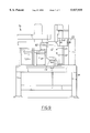
- FIG. 4 is a side view of a machine for folding the strip of plates into a core.
- FIG. 5 is a top plan view of the machine of FIG. 4.
- FIG. 6 is a top plan view of a heat exchanger structured in accord with the principles of the present invention prior to the links being folded.
- FIG. 7 is a top plan view of a heat exchanger structured in accord with the principles of the present invention after the links have been folded.
- FIG. 8 is a top plan view of a machine for bending the folded links in accord with the present invention.
- FIG. 9 is a side view of the machine of FIG. 8.
- FIGS. 10A and B are enlarged views of a portion of the machine of FIG. 8.
- FIG. 1 shows a plate-tube heat exchanger, generally designated by the numeral 10, in the form of an evaporator particularly adapted for use in an automobile air conditioning system.
- the heat exchanger 10 comprises a stack of formed, elongated plates 12, pairs of which are joined together in face-to-face relationship so that adjacent pairs provide alternate passageways for the flow of refrigerant therebetween as will be described further below.
- the plates may be joined in any of a variety of known processes, such as through brazing or a lamination process.
- Heat transfer fins 14 are positioned between joined pairs of plates 12 to provide increased heat transfer area as is well known in the art.
- the joined plate pairs and fin assemblies are contained within endsheets 16.
- the heat exchanger 10 includes an inlet port 20 and an outlet port 22 formed within a header 18 at either one or both ends of the heat exchanger 10.
- the header is in direct communication with the passageways between the joined pairs of plates 12 as will become apparent from the following description.
- the plates 12 have aligned apertures at the ends thereof providing communication between inlet and outlet ports 20, 22, respectively, of header 18.
- each of the plates can include apertures at either one or both ends thereof and the inlet and outlet ports 20, 22 can be located at opposite ends of the heat exchanger as is well known in the art.
- refrigerant is directed into the inlet port 20, passed through the pair plurality of joined plates 12 in a known manner. The refrigerant then exits through outlet ports 22 to complete the cooling cycle.
- the plate members 26 are formed from a single sheet of material 24 and are interconnected by a first set of deformable links 27 and a second set of deformable links 29 which will be described in greater detail below.
- Each of the plates 24 is generally planar and include a longitudinal axis denoted by line L--L and a transverse axis denoted by line T--T.
- the longitudinal axis of the plates (L--L) is parallel to the longitudinal axis of the heat exchanger core. Stated another way, the longitudinal axis of the heat exchanger core is perpendicular to the general direction of air flow passing through the core.
- the material 24 can be an aluminum material coated with an aluminum brazing alloy as is known in the art.
- a sheet of material 24 can either be of a predetermined length with a predetermined number of plate members 26 therein or may be formed as a continuous strip of material which is cut at a predetermined number of plates to form a heat exchanger of predetermined size.
- the plate members 26 are stamped using pneumatic and/or hydraulic activated details in a die controlled by a PLC ⁇ PLS or other computerized means known in the die pressing art.
- Each of the plate members 26 includes a pair of end portions 28 and an intermediate portion 30 therebetween.
- a plurality of apertures 32 can be formed in each of the end portions 28 or alternatively, a single aperture can be formed therein.
- the apertures are aligned when the heat exchanger is assembled to provide for a fluid conduit for the heat exchanger fluid to pass therethrough.
- the central aperture includes a radius portion. The radius portion provides for alignment of the inlet tube during its insertion into the core during the assembly process.
- Each of the intermediate portions 30 of the plate members 26 includes a plurality of beads 34 which, as is well known in the art, provide a circuitous path for the fluid to pass through the plate tube 12 to increase the turbulence of the fluid and provide for better heat transfer characteristics.
- selected end portions 28 of plate members 26 include end portions in which the apertures 32 are not included.
- These blanked ends 36 provide a baffle means in the heat exchanger by not allowing the fluid to pass thereby, forcing the fluid to assume a new flow direction within the heat exchanger. This provides an advantage over known heat exchangers without the baffle means which may not work as effectively as the present invention.
- the deformable links 27 and 29 are indented at predetermined locations to form a series of preferential bend zones indicated by dashed lines 58, 60.
- the bend zone indicated by dashed line 60 is the preferred bending zone when adjacent pairs of mating plates are to be folded face-to-face.
- the bend zones indicated by dashed lines 58 are the preferred locations at which the links 27, 29 are to be bent between pairs of mating plates.
- the distance between the bend zones 58 is preferably the same distance as the thickness of the fin members 14 to be inserted between the pairs of mating plates.
- the formation of the core element of the heat exchanger 10 can be accomplished by a corrugation machine.
- An example of one such machine which can be used to form a heat exchanger core is shown in FIGS. 4 and 5.
- the deformable links 27, 29 of the continuous strip of alternating plates are initially folded in a folding area by a fold forming machine to impart to the continuous strip an initial corrugation.
- the initial corrugated strip is then gathered in a gathering area by a gathering mechanism in which the folding of the deformable links is substantially completed and which results in a first set of folded deformable links and a second set of deformable links.
- the difference between the first and second set of deformable links results from the different bending zones, 58 and 60, located in each link. These differences will be described in greater detail below.
- Fin members 14 are then inserted between adjacent plate tubes by a fin stuffing machine.
- FIGS. 4 and 5 illustrate one example of a corrugation machine for fabricating such a heat exchanger core.
- the corrugation machine 100 has a base 102 including a feed mechanism 104 provided at one end for feeding the strip containing preformed plates to a material guide 106 which longitudinally aligns the strip in the machine, a fold forming mechanism 112, a gathering mechanism 116, a fin stuffing mechanism 120 and a link cut-off device 124.
- the corrugation machine 100 includes a process control monitor 108 and a fold forming mechanism 112.
- the process control monitor may be an optical or mechanical device adapted to detect predetermined plates such as the end plates of a core element and to count the number of plates between the predetermined plates to assure that each core severed from the continues strip of preformed plates will have the proper number of plates.
- the fold forming mechanism 112 consists of two pairs of opposing tractor or caterpillar drives 114 disposed on opposite sides of plates 12. The drives include lugs which engage the plates 12 such that as the drives rotate, the plates are caused to begin folding at the deformable links 27, 29.
- the gathering of the folded plates after they exit the fold forming mechanism 112 is accomplished by a pair of gathering belts 116, 118 (FIG. 5). Each of these belts has an upper and lower belt including lugs for engaging the plates and controlling the folding between mated pairs of plates as well as between individual plates.
- corrugated fins are inserted between mated pairs of plates. This is accomplished by a fin stuffing machine 120 which collects a predetermined number of fins corresponding to the number of spaces between mated pairs of plates. The fins are then dropped or pushed by the stuffing machine 120 into appropriate spaces between mated pairs of plates.
- An electronic controller 130 controls the number of fins aligned in the stuffing machine and the placing of the fins into the heat exchanger core. After the fins are stuffed into the core, the gathering belts are restarted to transport a new batch of folded plates under the fin stuffing machine.
- a link is cut to separate this formed core from the next adjacent core.
- the folded links are cut at both ends of the heat exchanger core, but only those links between adjacent cores are cut.
- FIG. 6 shows a top plan view of one end of the heat exchanger core 10 after the core has been through the link cut-off machine.
- the core includes a plurality of folded links projecting outwardly from the core. These links include a first set of links 70 and a second set of links 72.
- the first set of folded links 70 is formed at bend zones 58 and separate adjacent, mated pairs of plates to define the open space into which the fin members 14 are placed.
- the first set of folded links 70 are more open than the second set of folded links 72.
- the second set of folded links 72 are formed at bend zones 60 which act to mate two adjacent plate members to one another to form a plate tube. Because the mated plates must be physically connected to an adjacent plate, the second set of folded links 72 are somewhat more narrow than the first set of links 70.
- projecting folded links 70, 72 would interfere with packaging, such as a heat exchanger case, when inserted into such. Also, during transport of the cores 10 to a brazing furnace or for use in assembly, the cores 10 are often stacked one upon another. These projecting folded links interfere and get tangled with adjacent, stacked cores, often resulting in punctured or damaged heat exchanger cores. To overcome this problem, the projecting links are folded against the heat exchanger core such as is shown in FIG. 7.
- FIG. 7 shows that both of the first 70 and second 72 sets of folded links are folded against the heat exchanger core and do not extend or project outwardly as far from the core as before.
- Each plate member 12 is a generally planar, elongate member having a longitudinal and traverse axes. Fluid flow through mated plate pairs (plate tubes) typically is parallel to the longitudinal axis of the plates. Keeping this orientation, the first set of folded links 70 are folded against the core in a direction generally parallel to the longitudinal axis of the plate members.
- the second set of folded links 72 are folded in a direction different than the first set of links 70, although they could be folded the same. In the preferred embodiment, the second set of links 72 are folded in a direction generally perpendicular to the longitudinal axis of the plates 12, in a direction generally parallel to the transverse direction of the plates 12.
- FIGS. 8-10 show a machine for bending the folded links according to the present invention.
- the machine 76 can be an integrated part of the corrugation machine described in FIGS. 4 and 5, or may be a stand alone machine. After the heat exchanger cores 10 leave the link cut-off machine 124 and before they are sent to a brazing furnace, the cores are transported to the link bending machine 76.
- the machine 76 has a base 78 and a transport mechanism 79 for transporting the cores 10 to the work station 80 in the machine. After the cores 10 are transported to the machine 76, the cores are locked into a predetermined orientation, one which exposes the first set of folded links 70 outwardly from the machine 76.
- a reciprocating die or punch 82 activated hydraulically or pneumatically, engages the entire first set of folded links 70 and applies a force against the first set of links 70 in a direction generally perpendicularly to the plane of the plate members. This causes all the links in the first set 70 to bend instantaneously in a direction generally parallel to the longitudinal axis of the plate member 12.
- a pair of rollers 81 are urged against the second set of folded links 72.
- the pair of rollers 81 fold each of the links in the second set serially, or one after another.
- the rollers 81 apply a force against the links 72 in a direction generally perpendicular to the plane of the plates 12 and bend the links 72 in a direction generally parallel to the transverse axis (T--T) of the plate 12.
- T--T transverse axis
- the rollers 81 rotates at the end of a rigid arm 83 which can be hydraulically or pneumatically controlled.
- the arms 83 move fore and aft to contact the links 72 and reciprocate in a vertical, up-and-down direction to bend each of the links 72 serially.
- the rollers 81' can selectively engage and disengage the second set of links 72.
- the heat exchanger core 10 includes fluid manifolds (inlet and outlet) which project from the middle of the fluid tanks as opposed from the ends. With this design, the fluid manifolds are spaced between and project through the second set of folded links 72. The rollers 81' must be able to navigate around these manifolds to bend the links 72 without causing damage to the manifolds.
- FIG. 10B shows a design of a roller 81' which can accomplish this.
- the rollers 81' includes a flexible member 84 which contains a sensor.
- the sensor either optical or mechanical, determines the presence of the manifold or other obstruction and sends a signal to a controller which raises the rigid arms away from the core. After the obstruction has passed, the controller causes the arms and rollers to engage the links once again.
- the rollers 81' can be preprogrammed so that the controller automatically raises and lowers the rigid arms to avoid the manifold or other obstructions.
- the core is then placed into a brazing furnace and passed through a brazing operation in which the metal brazes together in order to form the completed article.
Abstract
Description
Claims (19)
Priority Applications (4)
| Application Number | Priority Date | Filing Date | Title |
|---|---|---|---|
| US08/992,324 US5937935A (en) | 1997-12-17 | 1997-12-17 | Heat exchanger and method of making the same |
| DE69814020T DE69814020T2 (en) | 1997-12-17 | 1998-11-05 | Heat exchanger and process for its manufacture |
| EP98309076A EP0927864B1 (en) | 1997-12-17 | 1998-11-05 | Heat exchanger and method of making the same |
| KR2019980025228U KR19990034673U (en) | 1997-12-17 | 1998-12-16 | heat transmitter |
Applications Claiming Priority (1)
| Application Number | Priority Date | Filing Date | Title |
|---|---|---|---|
| US08/992,324 US5937935A (en) | 1997-12-17 | 1997-12-17 | Heat exchanger and method of making the same |
Publications (1)
| Publication Number | Publication Date |
|---|---|
| US5937935A true US5937935A (en) | 1999-08-17 |
Family
ID=25538197
Family Applications (1)
| Application Number | Title | Priority Date | Filing Date |
|---|---|---|---|
| US08/992,324 Expired - Lifetime US5937935A (en) | 1997-12-17 | 1997-12-17 | Heat exchanger and method of making the same |
Country Status (4)
| Country | Link |
|---|---|
| US (1) | US5937935A (en) |
| EP (1) | EP0927864B1 (en) |
| KR (1) | KR19990034673U (en) |
| DE (1) | DE69814020T2 (en) |
Cited By (11)
| Publication number | Priority date | Publication date | Assignee | Title |
|---|---|---|---|---|
| US6152216A (en) * | 1998-10-13 | 2000-11-28 | DBB Fuel Cell Engines Gesellschaft mit beschrankter Haftung | Evaporator unit |
| US6212764B1 (en) * | 1997-12-17 | 2001-04-10 | Visteon Global Technologies, Inc. | Link bending machine |
| US6269869B1 (en) * | 1999-12-22 | 2001-08-07 | Visteon Global Technologies, Inc. | Continuous corrugated heat exchanger and method of making same |
| US6332266B1 (en) * | 1998-12-11 | 2001-12-25 | Halla Climate Control Corporation | Heat exchanger assembling apparatus |
| US6467536B1 (en) * | 1999-12-22 | 2002-10-22 | Visteon Global Technologies, Inc. | Evaporator and method of making same |
| US20060175047A1 (en) * | 2005-02-07 | 2006-08-10 | Denso Corporation | Heat exchanger, method of manufacturing heat exchanger and plate-shaped fin for heat exchanger |
| JP2010270953A (en) * | 2009-05-21 | 2010-12-02 | Mitsubishi Electric Corp | Drawn cup type heat exchanger |
| JP2010286222A (en) * | 2009-06-15 | 2010-12-24 | Showa Denko Kk | Heat exchanger |
| US20140352936A1 (en) * | 2011-12-30 | 2014-12-04 | Behr Gmbh & Co. Kg | Heat exchanger |
| US20140374074A1 (en) * | 2011-12-30 | 2014-12-25 | Behr Gmbh & Co. Kg | Heat exchanger |
| US10343239B2 (en) | 2015-11-20 | 2019-07-09 | Samsung Electronics Co., Ltd. | Apparatus and method for manufacturing heat exchanger |
Families Citing this family (1)
| Publication number | Priority date | Publication date | Assignee | Title |
|---|---|---|---|---|
| DE102010052621B4 (en) * | 2010-11-29 | 2014-03-13 | Benteler Automobiltechnik Gmbh | Method for producing a heat exchanger |
Citations (22)
| Publication number | Priority date | Publication date | Assignee | Title |
|---|---|---|---|---|
| US2006383A (en) * | 1932-11-22 | 1935-07-02 | Modine Mfg Co | Machine for fabricating radiator cores |
| US3207216A (en) * | 1963-02-27 | 1965-09-21 | Borg Warner | Heat exchanger |
| US3425113A (en) * | 1966-09-21 | 1969-02-04 | Reynolds Metals Co | Method of making composite sheet structures with internal passages by roll bonding |
| US3734171A (en) * | 1971-04-19 | 1973-05-22 | Singer Co | Coil for air duct installation |
| US3762031A (en) * | 1970-02-05 | 1973-10-02 | Graenges Essem Ab | Method for manufacturing elongate heat-exchange element blanks |
| US4175309A (en) * | 1978-06-15 | 1979-11-27 | General Motors Corporation | Conveyorized fin accumulator |
| US4274482A (en) * | 1978-08-21 | 1981-06-23 | Nihon Radiator Co., Ltd. | Laminated evaporator |
| US4350201A (en) * | 1981-01-12 | 1982-09-21 | United Aircraft Products, Inc. | Self fixturing heat exchanger |
| US4434643A (en) * | 1978-11-08 | 1984-03-06 | Reheat Ab | Method and a device for embossing heat exchanger plates |
| US4562630A (en) * | 1980-10-21 | 1986-01-07 | Gunnar Larsson | Method for the manufacture of heat exchanger elements |
| JPS61217697A (en) * | 1985-03-25 | 1986-09-27 | Nippon Denso Co Ltd | Laminated type heat exchanger |
| US4679410A (en) * | 1986-10-30 | 1987-07-14 | General Motors Corporation | Integral evaporator and accumulator for air conditioning system |
| JPS62203632A (en) * | 1986-02-28 | 1987-09-08 | Showa Alum Corp | Production of lamination type heat exchanger |
| JPS63187097A (en) * | 1987-01-28 | 1988-08-02 | Nippon Denso Co Ltd | Layered type heat exchanger |
| JPS63278621A (en) * | 1987-05-08 | 1988-11-16 | Nippon Denso Co Ltd | Heat exchanger |
| US4901414A (en) * | 1989-03-27 | 1990-02-20 | General Motors Corporation | Method for assembling pairs of heat exchanger plates |
| US5125453A (en) * | 1991-12-23 | 1992-06-30 | Ford Motor Company | Heat exchanger structure |
| US5507338A (en) * | 1995-08-30 | 1996-04-16 | Ford Motor Company | Tab for an automotive heat exchanger |
| US5603159A (en) * | 1994-09-29 | 1997-02-18 | Zexel Corporation | Method of producing heat exchangers |
| US5628114A (en) * | 1995-06-26 | 1997-05-13 | Stern; Mel | Screen frame and method of manufacture thereof |
| US5632080A (en) * | 1994-07-26 | 1997-05-27 | Burr Oak Tool & Gauge Company, Inc. | Tube cutter/bender to lacer transfer station |
| US5732460A (en) * | 1996-05-17 | 1998-03-31 | Livernois Research & Development Company | Corrugation machine for making a core for a heat exchanger |
Family Cites Families (5)
| Publication number | Priority date | Publication date | Assignee | Title |
|---|---|---|---|---|
| US3258832A (en) * | 1962-05-14 | 1966-07-05 | Gen Motors Corp | Method of making sheet metal heat exchangers |
| US3211118A (en) * | 1962-12-20 | 1965-10-12 | Borg Warner | Heat exchanger |
| JPS62203631A (en) * | 1986-02-28 | 1987-09-08 | Showa Alum Corp | Producton of lamination type heat exchanger |
| JPS63306394A (en) * | 1987-06-05 | 1988-12-14 | Nippon Denso Co Ltd | Laminated heat exchanger |
| US6212764B1 (en) * | 1997-12-17 | 2001-04-10 | Visteon Global Technologies, Inc. | Link bending machine |
-
1997
- 1997-12-17 US US08/992,324 patent/US5937935A/en not_active Expired - Lifetime
-
1998
- 1998-11-05 EP EP98309076A patent/EP0927864B1/en not_active Expired - Lifetime
- 1998-11-05 DE DE69814020T patent/DE69814020T2/en not_active Expired - Lifetime
- 1998-12-16 KR KR2019980025228U patent/KR19990034673U/en not_active Application Discontinuation
Patent Citations (22)
| Publication number | Priority date | Publication date | Assignee | Title |
|---|---|---|---|---|
| US2006383A (en) * | 1932-11-22 | 1935-07-02 | Modine Mfg Co | Machine for fabricating radiator cores |
| US3207216A (en) * | 1963-02-27 | 1965-09-21 | Borg Warner | Heat exchanger |
| US3425113A (en) * | 1966-09-21 | 1969-02-04 | Reynolds Metals Co | Method of making composite sheet structures with internal passages by roll bonding |
| US3762031A (en) * | 1970-02-05 | 1973-10-02 | Graenges Essem Ab | Method for manufacturing elongate heat-exchange element blanks |
| US3734171A (en) * | 1971-04-19 | 1973-05-22 | Singer Co | Coil for air duct installation |
| US4175309A (en) * | 1978-06-15 | 1979-11-27 | General Motors Corporation | Conveyorized fin accumulator |
| US4274482A (en) * | 1978-08-21 | 1981-06-23 | Nihon Radiator Co., Ltd. | Laminated evaporator |
| US4434643A (en) * | 1978-11-08 | 1984-03-06 | Reheat Ab | Method and a device for embossing heat exchanger plates |
| US4562630A (en) * | 1980-10-21 | 1986-01-07 | Gunnar Larsson | Method for the manufacture of heat exchanger elements |
| US4350201A (en) * | 1981-01-12 | 1982-09-21 | United Aircraft Products, Inc. | Self fixturing heat exchanger |
| JPS61217697A (en) * | 1985-03-25 | 1986-09-27 | Nippon Denso Co Ltd | Laminated type heat exchanger |
| JPS62203632A (en) * | 1986-02-28 | 1987-09-08 | Showa Alum Corp | Production of lamination type heat exchanger |
| US4679410A (en) * | 1986-10-30 | 1987-07-14 | General Motors Corporation | Integral evaporator and accumulator for air conditioning system |
| JPS63187097A (en) * | 1987-01-28 | 1988-08-02 | Nippon Denso Co Ltd | Layered type heat exchanger |
| JPS63278621A (en) * | 1987-05-08 | 1988-11-16 | Nippon Denso Co Ltd | Heat exchanger |
| US4901414A (en) * | 1989-03-27 | 1990-02-20 | General Motors Corporation | Method for assembling pairs of heat exchanger plates |
| US5125453A (en) * | 1991-12-23 | 1992-06-30 | Ford Motor Company | Heat exchanger structure |
| US5632080A (en) * | 1994-07-26 | 1997-05-27 | Burr Oak Tool & Gauge Company, Inc. | Tube cutter/bender to lacer transfer station |
| US5603159A (en) * | 1994-09-29 | 1997-02-18 | Zexel Corporation | Method of producing heat exchangers |
| US5628114A (en) * | 1995-06-26 | 1997-05-13 | Stern; Mel | Screen frame and method of manufacture thereof |
| US5507338A (en) * | 1995-08-30 | 1996-04-16 | Ford Motor Company | Tab for an automotive heat exchanger |
| US5732460A (en) * | 1996-05-17 | 1998-03-31 | Livernois Research & Development Company | Corrugation machine for making a core for a heat exchanger |
Cited By (15)
| Publication number | Priority date | Publication date | Assignee | Title |
|---|---|---|---|---|
| US6212764B1 (en) * | 1997-12-17 | 2001-04-10 | Visteon Global Technologies, Inc. | Link bending machine |
| US6152216A (en) * | 1998-10-13 | 2000-11-28 | DBB Fuel Cell Engines Gesellschaft mit beschrankter Haftung | Evaporator unit |
| US6332266B1 (en) * | 1998-12-11 | 2001-12-25 | Halla Climate Control Corporation | Heat exchanger assembling apparatus |
| US6269869B1 (en) * | 1999-12-22 | 2001-08-07 | Visteon Global Technologies, Inc. | Continuous corrugated heat exchanger and method of making same |
| US6438840B2 (en) | 1999-12-22 | 2002-08-27 | Visteon Global Technologies, Inc. | Method of making continuous corrugated heat exchanger |
| US6467536B1 (en) * | 1999-12-22 | 2002-10-22 | Visteon Global Technologies, Inc. | Evaporator and method of making same |
| US20060175047A1 (en) * | 2005-02-07 | 2006-08-10 | Denso Corporation | Heat exchanger, method of manufacturing heat exchanger and plate-shaped fin for heat exchanger |
| KR100741524B1 (en) * | 2005-02-07 | 2007-07-20 | 가부시키가이샤 덴소 | Heat exchanger, method of manufacturing heat exchanger and plate-shaped fin for heat exchanger |
| JP2010270953A (en) * | 2009-05-21 | 2010-12-02 | Mitsubishi Electric Corp | Drawn cup type heat exchanger |
| JP2010286222A (en) * | 2009-06-15 | 2010-12-24 | Showa Denko Kk | Heat exchanger |
| US20140352936A1 (en) * | 2011-12-30 | 2014-12-04 | Behr Gmbh & Co. Kg | Heat exchanger |
| US20140374074A1 (en) * | 2011-12-30 | 2014-12-25 | Behr Gmbh & Co. Kg | Heat exchanger |
| US9845997B2 (en) * | 2011-12-30 | 2017-12-19 | Mahle International Gmbh | Heat exchanger |
| US9958210B2 (en) * | 2011-12-30 | 2018-05-01 | Mahle International Gmbh | Heat exchanger |
| US10343239B2 (en) | 2015-11-20 | 2019-07-09 | Samsung Electronics Co., Ltd. | Apparatus and method for manufacturing heat exchanger |
Also Published As
| Publication number | Publication date |
|---|---|
| DE69814020T2 (en) | 2003-12-18 |
| KR19990034673U (en) | 1999-08-25 |
| EP0927864A3 (en) | 2000-03-01 |
| DE69814020D1 (en) | 2003-06-05 |
| EP0927864A2 (en) | 1999-07-07 |
| EP0927864B1 (en) | 2003-05-02 |
Similar Documents
| Publication | Publication Date | Title |
|---|---|---|
| EP0646231B1 (en) | Heat exchange tubes | |
| US5937935A (en) | Heat exchanger and method of making the same | |
| US5507338A (en) | Tab for an automotive heat exchanger | |
| EP0271319B1 (en) | Method of making a heat exchanger assembly with integral fin units | |
| US3780799A (en) | Heat exchangers and method of making same | |
| US5190101A (en) | Heat exchanger manifold | |
| US7140107B2 (en) | Stacking-type, multi-flow, heat exchangers and methods for manufacturing such heat exchangers | |
| US4173998A (en) | Formed coil assembly | |
| US4197625A (en) | Plate fin coil assembly | |
| US5855240A (en) | Automotive heat exchanger | |
| US5482115A (en) | Heat exchanger and plate fin therefor | |
| US5732460A (en) | Corrugation machine for making a core for a heat exchanger | |
| CZ130293A3 (en) | Process for producing metallic tube suitable for brazing and provided with holes for insertion of other tubes | |
| US6269869B1 (en) | Continuous corrugated heat exchanger and method of making same | |
| US5890288A (en) | Method for making a heat exchanger tube | |
| US4881311A (en) | Heat exchanger assembly with integral fin unit | |
| US6212764B1 (en) | Link bending machine | |
| EP0736346B1 (en) | Method of making an automotive evaporator | |
| US2998639A (en) | Method of making heat exchangers | |
| EP2990751A1 (en) | Heat exchanger fin retention feature | |
| US20040200070A1 (en) | Method of manufacturing tube and apparatus for manufacturing the same | |
| US2927369A (en) | Method of making multiple passage heat exchanger | |
| EP0866301A1 (en) | Heat exchanger and method of manufacturing same | |
| EP1111321A2 (en) | Beaded plate for a heat exchanger and method of making same | |
| JP2990301B2 (en) | Meandering heat exchanger with plate and fin, and method and apparatus for manufacturing the same |
Legal Events
| Date | Code | Title | Description |
|---|---|---|---|
| AS | Assignment |
Owner name: FORD MOTOR COMPANY, MICHIGAN Free format text: ASSIGNMENT OF ASSIGNORS INTEREST;ASSIGNORS:SCHORNHORST, CARL ECKHARDT;SELM, GERALD JOSEPH;WISE, KEVIN BENNETT;REEL/FRAME:009049/0452;SIGNING DATES FROM 19971216 TO 19971217 |
|
| STCF | Information on status: patent grant |
Free format text: PATENTED CASE |
|
| AS | Assignment |
Owner name: VISTEON GLOBAL TECHNOLOGIES, INC., MICHIGAN Free format text: ASSIGNMENT OF ASSIGNORS INTEREST;ASSIGNOR:FORD MOTOR COMPANY;REEL/FRAME:010968/0220 Effective date: 20000615 |
|
| FPAY | Fee payment |
Year of fee payment: 4 |
|
| FPAY | Fee payment |
Year of fee payment: 8 |
|
| AS | Assignment |
Owner name: JPMORGAN CHASE BANK, N.A., AS ADMINISTRATIVE AGENT Free format text: SECURITY AGREEMENT;ASSIGNOR:VISTEON GLOBAL TECHNOLOGIES, INC.;REEL/FRAME:020497/0733 Effective date: 20060613 |
|
| AS | Assignment |
Owner name: JPMORGAN CHASE BANK, TEXAS Free format text: SECURITY INTEREST;ASSIGNOR:VISTEON GLOBAL TECHNOLOGIES, INC.;REEL/FRAME:022368/0001 Effective date: 20060814 Owner name: JPMORGAN CHASE BANK,TEXAS Free format text: SECURITY INTEREST;ASSIGNOR:VISTEON GLOBAL TECHNOLOGIES, INC.;REEL/FRAME:022368/0001 Effective date: 20060814 |
|
| AS | Assignment |
Owner name: WILMINGTON TRUST FSB, AS ADMINISTRATIVE AGENT, MIN Free format text: ASSIGNMENT OF SECURITY INTEREST IN PATENTS;ASSIGNOR:JPMORGAN CHASE BANK, N.A., AS ADMINISTRATIVE AGENT;REEL/FRAME:022575/0186 Effective date: 20090415 Owner name: WILMINGTON TRUST FSB, AS ADMINISTRATIVE AGENT,MINN Free format text: ASSIGNMENT OF SECURITY INTEREST IN PATENTS;ASSIGNOR:JPMORGAN CHASE BANK, N.A., AS ADMINISTRATIVE AGENT;REEL/FRAME:022575/0186 Effective date: 20090415 |
|
| AS | Assignment |
Owner name: THE BANK OF NEW YORK MELLON, AS ADMINISTRATIVE AGE Free format text: ASSIGNMENT OF PATENT SECURITY INTEREST;ASSIGNOR:JPMORGAN CHASE BANK, N.A., A NATIONAL BANKING ASSOCIATION;REEL/FRAME:022974/0057 Effective date: 20090715 |
|
| AS | Assignment |
Owner name: VISTEON GLOBAL TECHNOLOGIES, INC., MICHIGAN Free format text: RELEASE BY SECURED PARTY AGAINST SECURITY INTEREST IN PATENTS RECORDED AT REEL 022974 FRAME 0057;ASSIGNOR:THE BANK OF NEW YORK MELLON;REEL/FRAME:025095/0711 Effective date: 20101001 |
|
| AS | Assignment |
Owner name: VISTEON GLOBAL TECHNOLOGIES, INC., MICHIGAN Free format text: RELEASE BY SECURED PARTY AGAINST SECURITY INTEREST IN PATENTS RECORDED AT REEL 022575 FRAME 0186;ASSIGNOR:WILMINGTON TRUST FSB, AS ADMINISTRATIVE AGENT;REEL/FRAME:025105/0201 Effective date: 20101001 |
|
| AS | Assignment |
Owner name: MORGAN STANLEY SENIOR FUNDING, INC., AS AGENT, NEW Free format text: SECURITY AGREEMENT (REVOLVER);ASSIGNORS:VISTEON CORPORATION;VC AVIATION SERVICES, LLC;VISTEON ELECTRONICS CORPORATION;AND OTHERS;REEL/FRAME:025238/0298 Effective date: 20101001 Owner name: MORGAN STANLEY SENIOR FUNDING, INC., AS AGENT, NEW Free format text: SECURITY AGREEMENT;ASSIGNORS:VISTEON CORPORATION;VC AVIATION SERVICES, LLC;VISTEON ELECTRONICS CORPORATION;AND OTHERS;REEL/FRAME:025241/0317 Effective date: 20101007 |
|
| FPAY | Fee payment |
Year of fee payment: 12 |
|
| AS | Assignment |
Owner name: VISTEON INTERNATIONAL BUSINESS DEVELOPMENT, INC., Free format text: RELEASE BY SECURED PARTY AGAINST SECURITY INTEREST IN PATENTS ON REEL 025241 FRAME 0317;ASSIGNOR:MORGAN STANLEY SENIOR FUNDING, INC.;REEL/FRAME:026178/0412 Effective date: 20110406 Owner name: VISTEON INTERNATIONAL HOLDINGS, INC., MICHIGAN Free format text: RELEASE BY SECURED PARTY AGAINST SECURITY INTEREST IN PATENTS ON REEL 025241 FRAME 0317;ASSIGNOR:MORGAN STANLEY SENIOR FUNDING, INC.;REEL/FRAME:026178/0412 Effective date: 20110406 Owner name: VISTEON ELECTRONICS CORPORATION, MICHIGAN Free format text: RELEASE BY SECURED PARTY AGAINST SECURITY INTEREST IN PATENTS ON REEL 025241 FRAME 0317;ASSIGNOR:MORGAN STANLEY SENIOR FUNDING, INC.;REEL/FRAME:026178/0412 Effective date: 20110406 Owner name: VISTEON CORPORATION, MICHIGAN Free format text: RELEASE BY SECURED PARTY AGAINST SECURITY INTEREST IN PATENTS ON REEL 025241 FRAME 0317;ASSIGNOR:MORGAN STANLEY SENIOR FUNDING, INC.;REEL/FRAME:026178/0412 Effective date: 20110406 Owner name: VISTEON GLOBAL TECHNOLOGIES, INC., MICHIGAN Free format text: RELEASE BY SECURED PARTY AGAINST SECURITY INTEREST IN PATENTS ON REEL 025241 FRAME 0317;ASSIGNOR:MORGAN STANLEY SENIOR FUNDING, INC.;REEL/FRAME:026178/0412 Effective date: 20110406 Owner name: VC AVIATION SERVICES, LLC, MICHIGAN Free format text: RELEASE BY SECURED PARTY AGAINST SECURITY INTEREST IN PATENTS ON REEL 025241 FRAME 0317;ASSIGNOR:MORGAN STANLEY SENIOR FUNDING, INC.;REEL/FRAME:026178/0412 Effective date: 20110406 Owner name: VISTEON EUROPEAN HOLDING, INC., MICHIGAN Free format text: RELEASE BY SECURED PARTY AGAINST SECURITY INTEREST IN PATENTS ON REEL 025241 FRAME 0317;ASSIGNOR:MORGAN STANLEY SENIOR FUNDING, INC.;REEL/FRAME:026178/0412 Effective date: 20110406 Owner name: VISTEON SYSTEMS, LLC, MICHIGAN Free format text: RELEASE BY SECURED PARTY AGAINST SECURITY INTEREST IN PATENTS ON REEL 025241 FRAME 0317;ASSIGNOR:MORGAN STANLEY SENIOR FUNDING, INC.;REEL/FRAME:026178/0412 Effective date: 20110406 Owner name: VISTEON GLOBAL TREASURY, INC., MICHIGAN Free format text: RELEASE BY SECURED PARTY AGAINST SECURITY INTEREST IN PATENTS ON REEL 025241 FRAME 0317;ASSIGNOR:MORGAN STANLEY SENIOR FUNDING, INC.;REEL/FRAME:026178/0412 Effective date: 20110406 |
|
| AS | Assignment |
Owner name: HALLA VISTEON CLIMATE CONTROL CORPORATION, KOREA, Free format text: ASSIGNMENT OF ASSIGNORS INTEREST;ASSIGNOR:VISTEON GLOBAL TECHNOLOGIES, INC.;REEL/FRAME:030935/0969 Effective date: 20130726 |
|
| AS | Assignment |
Owner name: VISTEON GLOBAL TREASURY, INC., MICHIGAN Free format text: RELEASE OF SECURITY INTEREST IN INTELLECTUAL PROPERTY;ASSIGNOR:MORGAN STANLEY SENIOR FUNDING, INC.;REEL/FRAME:033107/0717 Effective date: 20140409 Owner name: VISTEON INTERNATIONAL BUSINESS DEVELOPMENT, INC., Free format text: RELEASE OF SECURITY INTEREST IN INTELLECTUAL PROPERTY;ASSIGNOR:MORGAN STANLEY SENIOR FUNDING, INC.;REEL/FRAME:033107/0717 Effective date: 20140409 Owner name: VISTEON CORPORATION, MICHIGAN Free format text: RELEASE OF SECURITY INTEREST IN INTELLECTUAL PROPERTY;ASSIGNOR:MORGAN STANLEY SENIOR FUNDING, INC.;REEL/FRAME:033107/0717 Effective date: 20140409 Owner name: VISTEON GLOBAL TECHNOLOGIES, INC., MICHIGAN Free format text: RELEASE OF SECURITY INTEREST IN INTELLECTUAL PROPERTY;ASSIGNOR:MORGAN STANLEY SENIOR FUNDING, INC.;REEL/FRAME:033107/0717 Effective date: 20140409 Owner name: VC AVIATION SERVICES, LLC, MICHIGAN Free format text: RELEASE OF SECURITY INTEREST IN INTELLECTUAL PROPERTY;ASSIGNOR:MORGAN STANLEY SENIOR FUNDING, INC.;REEL/FRAME:033107/0717 Effective date: 20140409 Owner name: VISTEON INTERNATIONAL HOLDINGS, INC., MICHIGAN Free format text: RELEASE OF SECURITY INTEREST IN INTELLECTUAL PROPERTY;ASSIGNOR:MORGAN STANLEY SENIOR FUNDING, INC.;REEL/FRAME:033107/0717 Effective date: 20140409 Owner name: VISTEON SYSTEMS, LLC, MICHIGAN Free format text: RELEASE OF SECURITY INTEREST IN INTELLECTUAL PROPERTY;ASSIGNOR:MORGAN STANLEY SENIOR FUNDING, INC.;REEL/FRAME:033107/0717 Effective date: 20140409 Owner name: VISTEON ELECTRONICS CORPORATION, MICHIGAN Free format text: RELEASE OF SECURITY INTEREST IN INTELLECTUAL PROPERTY;ASSIGNOR:MORGAN STANLEY SENIOR FUNDING, INC.;REEL/FRAME:033107/0717 Effective date: 20140409 Owner name: VISTEON EUROPEAN HOLDINGS, INC., MICHIGAN Free format text: RELEASE OF SECURITY INTEREST IN INTELLECTUAL PROPERTY;ASSIGNOR:MORGAN STANLEY SENIOR FUNDING, INC.;REEL/FRAME:033107/0717 Effective date: 20140409 |
|
| AS | Assignment |
Owner name: HANON SYSTEMS, KOREA, REPUBLIC OF Free format text: CHANGE OF NAME;ASSIGNOR:HALLA VISTEON CLIMATE CONTROL CORPORATION;REEL/FRAME:037007/0103 Effective date: 20150728 |