US5881525A - Window screen frame - Google Patents
Window screen frame Download PDFInfo
- Publication number
- US5881525A US5881525A US08/958,650 US95865097A US5881525A US 5881525 A US5881525 A US 5881525A US 95865097 A US95865097 A US 95865097A US 5881525 A US5881525 A US 5881525A
- Authority
- US
- United States
- Prior art keywords
- wall
- frame
- leg
- side wall
- tube
- Prior art date
- Legal status (The legal status is an assumption and is not a legal conclusion. Google has not performed a legal analysis and makes no representation as to the accuracy of the status listed.)
- Expired - Fee Related
Links
- 239000002184 metal Substances 0.000 claims abstract description 11
- 239000004744 fabric Substances 0.000 claims description 4
- 230000001154 acute effect Effects 0.000 claims 4
- 239000004593 Epoxy Substances 0.000 description 1
- 150000001875 compounds Chemical class 0.000 description 1
- 238000010276 construction Methods 0.000 description 1
Images

Classifications
-
- E—FIXED CONSTRUCTIONS
- E06—DOORS, WINDOWS, SHUTTERS, OR ROLLER BLINDS IN GENERAL; LADDERS
- E06B—FIXED OR MOVABLE CLOSURES FOR OPENINGS IN BUILDINGS, VEHICLES, FENCES OR LIKE ENCLOSURES IN GENERAL, e.g. DOORS, WINDOWS, BLINDS, GATES
- E06B9/00—Screening or protective devices for wall or similar openings, with or without operating or securing mechanisms; Closures of similar construction
- E06B9/52—Devices affording protection against insects, e.g. fly screens; Mesh windows for other purposes
Definitions
- the invention pertains to window screen frames, more particularly to a window screen frame that is made by folding a strip of formed stock.
- U.S. Pat. No. 1,596,950 patented Aug. 24, 1926 by P. F. Semonin describes a stamped sheet metal strip folded into a frame.
- a narrow longitudinal portion of the strip forms the outer wall of the frame.
- the side walls of the frame are 90 degree folded upward portions of the strip which are each folded again toward one another so that a longitudinal slot is formed along the inner center of each leg of the frame by the facing edges of the side walls.
- opposite portions of the side walls are removed each by 90 degree and 45 degree cuts which meet at the longitudinal fold line between the side wall and the narrow longitudinal portion.
- the 90 degree and the 45 degree cuts in each wall abut.
- a hole near each corner is formed by circular notches in the facing edges of the longitudinal slot so that a rod mounting one side of the screen can be held within the leg behind the slot in each of two opposing legs of the frame.
- U.S. Pat. No. 5,018,263 patented May 28, 1991 by M. J. Stern describes a continuous thin die cut metal strip which when folded to form a corner of a frame, has the side walls of one leg of the frame epoxy fastened within the adjacent leg of the frame to 45 degree end-cut side walls of the adjacent leg.
- the side walls are further formed into longitudinal channels extending the length of each leg for receiving screen fabric.
- the frame can be made by folding the sheet into a tube and screen holding element, and folding the tube to form corners of the frame.
- compound lock means is operated by folding the tube to lock the fold.
- a metallic frame for a screen formed from a metal sheet in a single unit includes an outer wall connected to a first side wall and to a second side wall that is opposite the first side wall, and an inner wall connected to the first side wall and to the second side wall, the outer wall, first side wall, second side wall, and inner wall form a tube in which the inner wall is closed.
- a first V-cut across the tube extends through the inner wall the first side wall and the second side wall, and has an apex at the outer wall.
- the outer wall has a fold at the apex which forms a first corner of the screen frame and makes of the tube a first leg of the frame and a second leg of the frame attached to the first leg by the outer wall at the first corner.
- Means for holding screen fabric extends from the tube.
- Locking means comprising the inner wall and one of the first side wall and the second side wall is configured to move in the direction of the fold and crosswise to the direction of the fold for locking the tube into the fold when the tube is folded at the apex.
- a first portion of the inner wall on the first leg extends through the inner wall on the second leg and holds the fold closed.
- the first portion is preferably spaced from the first side wall and the second side wall.
- the tube includes catch means on the inner wall at the first end of the tube, and the frame further includes an insert mounted in the tube and spring hook means on the insert in the catch means.
- the insert attaches the first end to the second end at a corner of the frame.
- the catch means is preferably spaced from the first side wall and from the second side wall.
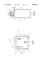
- FIG. 1 is a front schematic view of an assembled frame of the invention, and in broken line three legs of the frame in a position before they are folded to make the frame.
- FIG. 2 is a cross section view of a leg of the frame of FIG. 1 taken along line 2--2 and rotated.
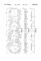
- FIG. 3 is a top schematic view of the flat metal strip blank for constructing the frame of FIG. 1.
- FIG. 4 is a top view of the blank of FIG. 1, folded longitudinally for constructing the frame of FIG. 1.
- FIG. 5 is a front view of the blank of FIG. 4.
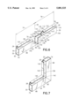
- FIG. 6 is a perspective view of a corner section of the longitudinally folded blank of FIG. 4. Only the corner ends of the frame legs are shown.
- FIG. 7 is a perspective view of the corner section of FIG. 6, folded into a completed corner. Only the corner ends of the frame legs are shown.
- FIG. 8 is a perspective view of the extreme ends of the blank of FIG. 4 oriented for attaching together by a corner fastener. Only the corner ends of the frame legs are shown.
- FIG. 9 is a perspective view of the corner ends of the legs of FIG. 8 attached together by the corner fastener.
- frame 20 is designed to receive as window screen 24 which is held in channel 28 by rubber spline 32.
- Corners 34, 36, and 38 of frame 20 are made by folding stock strip 40 on fold lines 44, 46 and 48 respectively which coincide respectively with the apexes of V-cut pairs 45, 50; 47, 51; and 49, 53.
- Corner 42 is made by attaching ends 52 and 54 of the frame length segment of stock strip 40 together.
- Stock strip 40 is preferably made by stamping from sheet metal ribbon in a continuous operation. Individual frame length segments are then separated from the ribbon. FIG. 3 shows one frame length.
- stock strip 40 is folded to about 90 degrees along longitudinal lines 60 and 62 to form side walls 64 and 66.
- Strip 70 forms outer wall 74 of the frame.
- Sections 76, 78, 80 and 82 respectively form legs 86, 88, 90, and 92 of the frame.
- Fold lines 44, 46, and 48 form corners 34, 36, and 38 respectively.
- the thin wall sheet metal is folded at fold lines 60, 62, 108, and 102 to form tube 30, and folded on lines 104, 106, 110, 112, and 114 to make channel 28.
- strip 116 is covered by strip 118, and strip 120 is covered by strips 122 and 124.
- Inner wall 140 of the frame comprises strip 132 in section 76, combination strips 135 and 134, in section 78, strip 136 in section 80, and strip 138 in section 82 which are adjacent to fold line 102, and strip 139, 137, 143, and 145 which are adjacent to fold line 108 in sections 76, 78, 80 and 82 respectively.
- Outer wall 74, side walls 64 and 66, and inner wall 140 are continuous around the tube, extending along a longitudinal portion of each leg.
- strip 40 folds on lines 60, 62, 108, and 102 to form tube 30.
- Folds on lines 104, 106, 110, 112, and 114 form channel 28 wherein strip 116 is covered by strip 118, and strip 120 is covered by strips 122 and 124 like in section 78.
- Tab 144 of leg 88 extends from inner wall 140 generally parallel with inner wall 140 and transverse to the length of leg 86 side walls 64, 66 at the center of inner wall 140, spaced from side walls 64, 66, through inner wall 140 into tube 30 and hooks by notch 142 onto wall 140, behind wall 140.
- Tube 30 is the same diameter on both sides of the V-cut.
- walls 64 and 66 of the section 78 leg are inserted into tube 30 between walls 64 and 66 of the section 76 leg, side walls 64 and 66 of the section 78 leg are forced toward one another about slot 150.
- Strips 135 and 137 provide a spring out resistance to the closing force that makes the telescoping walls fit tightly together which prevents twisting of the frame at the folded corner.
- walls 64 and 66 about slot 150 are forced closer together where they are inserted in the tube than where they are attached to wall 140 where it is closed 158, which moves strips 135 and 137 closer together on tab 144 locking it between them.
- tab 160 locks behind strips 135 and 137 which comprise inner wall 140 at section 78.
- tab 162 locks behind strips 135 and 137 which comprise inner wall 140 at section 82.
- tab 144 cam surfaces 170 and 172 bear laterally against inner wall strips 135 and 137 as the tab enters through inner wall 140, so that tab 144 cams strips 135 and 137 further apart and also cams side walls 64 and 66 further apart. This is in opposition to the squeezing force applied by the tube that they enter.
- tab 160 of section 80 enters through inner wall 140, spreading apart strips 135 and 137 of inner wall 140 of section 78 and locks behind them within the tube of that leg.
- tab 162 enters through inner wall 140, spreading apart strips 135 and 137 of inner wall 140 of section 82 and locks behind them within the tube of that leg.
- hook 180 on resilient arm 182 is forced into hole 184 in inner wall 140 by arm 182 when plastic bracket 190 is forced into tube 30 at end 52 of section 76.
- Plastic bracket 190 closely fits tube 30. The configuration prevents rotation or cocking of tube 30.
- Hook 192 on resilient arm 193 fits into hole 194 in inner wall 140 when the bracket is forced into tube 30 at end 54 of section 82.
Landscapes
- Engineering & Computer Science (AREA)
- Structural Engineering (AREA)
- Life Sciences & Earth Sciences (AREA)
- Insects & Arthropods (AREA)
- Pest Control & Pesticides (AREA)
- Architecture (AREA)
- Civil Engineering (AREA)
- Toys (AREA)
Abstract
Description
Claims (12)
Priority Applications (1)
| Application Number | Priority Date | Filing Date | Title |
|---|---|---|---|
| US08/958,650 US5881525A (en) | 1997-10-27 | 1997-10-27 | Window screen frame |
Applications Claiming Priority (1)
| Application Number | Priority Date | Filing Date | Title |
|---|---|---|---|
| US08/958,650 US5881525A (en) | 1997-10-27 | 1997-10-27 | Window screen frame |
Publications (1)
| Publication Number | Publication Date |
|---|---|
| US5881525A true US5881525A (en) | 1999-03-16 |
Family
ID=25501153
Family Applications (1)
| Application Number | Title | Priority Date | Filing Date |
|---|---|---|---|
| US08/958,650 Expired - Fee Related US5881525A (en) | 1997-10-27 | 1997-10-27 | Window screen frame |
Country Status (1)
| Country | Link |
|---|---|
| US (1) | US5881525A (en) |
Cited By (20)
| Publication number | Priority date | Publication date | Assignee | Title |
|---|---|---|---|---|
| US6109331A (en) * | 1997-11-26 | 2000-08-29 | Story, Jr.; Paul J. | Screen frame and screen door |
| US6681833B2 (en) | 2002-04-23 | 2004-01-27 | Saint-Gobain Bayform America, Inc. | Screen frame having corners under compression |
| US20040020157A1 (en) * | 2002-08-01 | 2004-02-05 | Home Improvement System, Inc. | Free-standing window screen fabrication system |
| US6845593B2 (en) | 2002-03-01 | 2005-01-25 | Silverline Building Products Corp. | Movable window frames having retaining latches |
| US20050103964A1 (en) * | 2003-11-17 | 2005-05-19 | Sonoco Development, Inc. | Tubular structure for supporting a product |
| US20050135877A1 (en) * | 2003-12-22 | 2005-06-23 | Anchor Tool & Die Company | Door frame miter brace |
| US20050257496A1 (en) * | 2004-05-19 | 2005-11-24 | Martineau Robert C | Frame for supporting an article and a method of forming a corner of the frame |
| US20060174588A1 (en) * | 2005-01-11 | 2006-08-10 | Anderson Audrey E | Stabilizing brace for a window buck |
| US7251917B2 (en) * | 2003-06-11 | 2007-08-07 | Sava Cvek | Methods and arrangements for securing fabric |
| US20080134627A1 (en) * | 2006-11-17 | 2008-06-12 | Formtek Metal Forming, Inc. | Window spacer and corner-fastening concept |
| WO2008131759A1 (en) * | 2007-04-26 | 2008-11-06 | Vkr Holding A/S | A screening arrangement comprising means for mounting side rails and method of mounting such a screening arrangement |
| US20090172586A1 (en) * | 2007-12-31 | 2009-07-02 | Lori Weaver | Window screen using woven image |
| US20100077694A1 (en) * | 2008-09-30 | 2010-04-01 | Mark Quintile | Frame member fastening device and method of manufacture |
| US20100242400A1 (en) * | 2009-03-27 | 2010-09-30 | Sawyers Jeff V | Frame Assembly And A Method Of Manufacturing The Same |
| US20110192556A1 (en) * | 2010-02-08 | 2011-08-11 | Frey Robert M | Groove-Mount Fabric Display System With Two-Part Frame |
| US20110265387A1 (en) * | 2010-04-30 | 2011-11-03 | Industries Spectal Inc. | Modular window assembly |
| USRE43457E1 (en) * | 1996-09-20 | 2012-06-12 | Justin J. Anderson | Window buck and method of assembly |
| EP2690246A1 (en) * | 2007-04-26 | 2014-01-29 | VKR Holding A/S | A screening arrangement comprising means for mounting side rails and method of mounting such a screening arrangement |
| DE102014000770A1 (en) * | 2013-11-08 | 2015-05-13 | Johnson Controls Gmbh | Seat part, backrest and vehicle seat |
| US20150224555A1 (en) * | 2012-01-10 | 2015-08-13 | Seoul Laser Dieboard System Co., Ltd. | Device and method for generating channel letters |
Citations (20)
| Publication number | Priority date | Publication date | Assignee | Title |
|---|---|---|---|---|
| US1596950A (en) * | 1923-05-09 | 1926-08-24 | Paul F Semonin | Fire screen |
| US1695091A (en) * | 1927-07-19 | 1928-12-11 | Harry H Everhard | Ventilating screen |
| US1775717A (en) * | 1929-04-09 | 1930-09-16 | Harry H Everhard | Screen-frame construction |
| US2006925A (en) * | 1934-07-13 | 1935-07-02 | Karl Oswald | Bag frame and method of making it |
| US2045770A (en) * | 1935-06-03 | 1936-06-30 | Golden Abraham | Picture frame and method of making the same |
| US2094991A (en) * | 1936-04-18 | 1937-10-05 | Lang Albert | Metal screen and method of manufacture |
| US2312721A (en) * | 1941-10-22 | 1943-03-02 | Roll Away Window Screen Compan | Window screen frame |
| US3097684A (en) * | 1960-01-14 | 1963-07-16 | Le Tarte Company Inc | Method of forming a closed corner in a hollow rectilinear metal workpiece |
| US3327766A (en) * | 1965-09-23 | 1967-06-27 | Air Balance | Damper frame |
| US3376670A (en) * | 1966-08-31 | 1968-04-09 | Excel Corp | Window sash and method for making same |
| US3879894A (en) * | 1973-02-05 | 1975-04-29 | Anderson Mfg Co V E | Sliding screen door |
| US4112622A (en) * | 1976-09-07 | 1978-09-12 | Empire Metal Products Corp. | Roller assembly for sliding screen door, and the like |
| US4357744A (en) * | 1980-06-05 | 1982-11-09 | Mckenzie Everett R | Method of connecting insulated glass frame |
| US4420920A (en) * | 1979-08-29 | 1983-12-20 | Hewitt Michael John | Cored plastics profiles and manufacture of frames for windows and the like therefrom |
| US4462237A (en) * | 1979-02-15 | 1984-07-31 | Josef Kauferle KG | Method of bending frame material for the production of compound plates, particularly compound glass panes |
| US4503640A (en) * | 1983-03-17 | 1985-03-12 | Stern Melvin J | Unitized construction for sliding closures and method for making |
| US4562677A (en) * | 1983-11-03 | 1986-01-07 | Stavebni Strojirenstvi A Lehka Prefabrikace Generalni Reditelstvi | Metal door frame constructed of a channel section and method of making same |
| US4628582A (en) * | 1981-12-04 | 1986-12-16 | Glass Equipment Development, Inc. | Method of making spacer frame for an insulating glass panel |
| US4665652A (en) * | 1981-04-10 | 1987-05-19 | Norfab, Inc. | Door frame structure |
| US5018263A (en) * | 1989-10-02 | 1991-05-28 | Stern Melvin J | Method for making a metal screen door frame |
-
1997
- 1997-10-27 US US08/958,650 patent/US5881525A/en not_active Expired - Fee Related
Patent Citations (20)
| Publication number | Priority date | Publication date | Assignee | Title |
|---|---|---|---|---|
| US1596950A (en) * | 1923-05-09 | 1926-08-24 | Paul F Semonin | Fire screen |
| US1695091A (en) * | 1927-07-19 | 1928-12-11 | Harry H Everhard | Ventilating screen |
| US1775717A (en) * | 1929-04-09 | 1930-09-16 | Harry H Everhard | Screen-frame construction |
| US2006925A (en) * | 1934-07-13 | 1935-07-02 | Karl Oswald | Bag frame and method of making it |
| US2045770A (en) * | 1935-06-03 | 1936-06-30 | Golden Abraham | Picture frame and method of making the same |
| US2094991A (en) * | 1936-04-18 | 1937-10-05 | Lang Albert | Metal screen and method of manufacture |
| US2312721A (en) * | 1941-10-22 | 1943-03-02 | Roll Away Window Screen Compan | Window screen frame |
| US3097684A (en) * | 1960-01-14 | 1963-07-16 | Le Tarte Company Inc | Method of forming a closed corner in a hollow rectilinear metal workpiece |
| US3327766A (en) * | 1965-09-23 | 1967-06-27 | Air Balance | Damper frame |
| US3376670A (en) * | 1966-08-31 | 1968-04-09 | Excel Corp | Window sash and method for making same |
| US3879894A (en) * | 1973-02-05 | 1975-04-29 | Anderson Mfg Co V E | Sliding screen door |
| US4112622A (en) * | 1976-09-07 | 1978-09-12 | Empire Metal Products Corp. | Roller assembly for sliding screen door, and the like |
| US4462237A (en) * | 1979-02-15 | 1984-07-31 | Josef Kauferle KG | Method of bending frame material for the production of compound plates, particularly compound glass panes |
| US4420920A (en) * | 1979-08-29 | 1983-12-20 | Hewitt Michael John | Cored plastics profiles and manufacture of frames for windows and the like therefrom |
| US4357744A (en) * | 1980-06-05 | 1982-11-09 | Mckenzie Everett R | Method of connecting insulated glass frame |
| US4665652A (en) * | 1981-04-10 | 1987-05-19 | Norfab, Inc. | Door frame structure |
| US4628582A (en) * | 1981-12-04 | 1986-12-16 | Glass Equipment Development, Inc. | Method of making spacer frame for an insulating glass panel |
| US4503640A (en) * | 1983-03-17 | 1985-03-12 | Stern Melvin J | Unitized construction for sliding closures and method for making |
| US4562677A (en) * | 1983-11-03 | 1986-01-07 | Stavebni Strojirenstvi A Lehka Prefabrikace Generalni Reditelstvi | Metal door frame constructed of a channel section and method of making same |
| US5018263A (en) * | 1989-10-02 | 1991-05-28 | Stern Melvin J | Method for making a metal screen door frame |
Cited By (37)
| Publication number | Priority date | Publication date | Assignee | Title |
|---|---|---|---|---|
| USRE43457E1 (en) * | 1996-09-20 | 2012-06-12 | Justin J. Anderson | Window buck and method of assembly |
| US6109331A (en) * | 1997-11-26 | 2000-08-29 | Story, Jr.; Paul J. | Screen frame and screen door |
| US6845593B2 (en) | 2002-03-01 | 2005-01-25 | Silverline Building Products Corp. | Movable window frames having retaining latches |
| US6681833B2 (en) | 2002-04-23 | 2004-01-27 | Saint-Gobain Bayform America, Inc. | Screen frame having corners under compression |
| US20040020157A1 (en) * | 2002-08-01 | 2004-02-05 | Home Improvement System, Inc. | Free-standing window screen fabrication system |
| US8061107B2 (en) | 2003-06-11 | 2011-11-22 | Sava Cvek | Methods and arrangements for securing fabric |
| US7251917B2 (en) * | 2003-06-11 | 2007-08-07 | Sava Cvek | Methods and arrangements for securing fabric |
| US20080028716A1 (en) * | 2003-06-11 | 2008-02-07 | Sava Cvek | Methods and Arrangements for Securing Fabric |
| US20050103964A1 (en) * | 2003-11-17 | 2005-05-19 | Sonoco Development, Inc. | Tubular structure for supporting a product |
| US7028964B2 (en) * | 2003-11-17 | 2006-04-18 | Sonoco Development, Inc. | Tubular structure for supporting a product |
| US20050135877A1 (en) * | 2003-12-22 | 2005-06-23 | Anchor Tool & Die Company | Door frame miter brace |
| US7223044B2 (en) * | 2003-12-22 | 2007-05-29 | Anchor Tool & Die Company | Door frame miter brace |
| US20050257496A1 (en) * | 2004-05-19 | 2005-11-24 | Martineau Robert C | Frame for supporting an article and a method of forming a corner of the frame |
| US7418806B2 (en) | 2004-05-19 | 2008-09-02 | Quanex Corporation | Frame for supporting an article and a method of forming a corner of the frame |
| US20060174588A1 (en) * | 2005-01-11 | 2006-08-10 | Anderson Audrey E | Stabilizing brace for a window buck |
| US20080134627A1 (en) * | 2006-11-17 | 2008-06-12 | Formtek Metal Forming, Inc. | Window spacer and corner-fastening concept |
| US8104238B2 (en) * | 2006-11-17 | 2012-01-31 | Formtek Metal Forming, Inc. | Window spacer and corner-fastening concept |
| EP2690246A1 (en) * | 2007-04-26 | 2014-01-29 | VKR Holding A/S | A screening arrangement comprising means for mounting side rails and method of mounting such a screening arrangement |
| US20100116449A1 (en) * | 2007-04-26 | 2010-05-13 | Henning Ebbesen | Screening arrangement comprising means for mounting side rails and method of mounting such a screening arrangement |
| US8833426B2 (en) | 2007-04-26 | 2014-09-16 | Vkr Holding A/S | Screening arrangement comprising means for mounting side rails and method of mounting such a screening arrangement |
| CN101663457B (en) * | 2007-04-26 | 2014-06-11 | Vkr控股公司 | A screening arrangement comprising means for mounting side rails and method of mounting such a screening arrangement |
| WO2008131759A1 (en) * | 2007-04-26 | 2008-11-06 | Vkr Holding A/S | A screening arrangement comprising means for mounting side rails and method of mounting such a screening arrangement |
| US7997035B2 (en) * | 2007-12-31 | 2011-08-16 | Lori Weaver | Window screen using woven image |
| US20090172586A1 (en) * | 2007-12-31 | 2009-07-02 | Lori Weaver | Window screen using woven image |
| US20100077694A1 (en) * | 2008-09-30 | 2010-04-01 | Mark Quintile | Frame member fastening device and method of manufacture |
| US8087208B2 (en) | 2008-09-30 | 2012-01-03 | Mark Quintile | Frame member fastening device and method of manufacture |
| US20100242400A1 (en) * | 2009-03-27 | 2010-09-30 | Sawyers Jeff V | Frame Assembly And A Method Of Manufacturing The Same |
| US8528293B2 (en) | 2009-03-27 | 2013-09-10 | Quanex Building Products Corporation | Foldable cornerlock for a frame assembly |
| US8572925B2 (en) | 2009-03-27 | 2013-11-05 | Quanex Building Products Corporation | Frame assembly and a method of manufacturing the same |
| US20100242399A1 (en) * | 2009-03-27 | 2010-09-30 | Sawyers Jeff V | Foldable Cornerlock For A Frame Assembly |
| US8240072B2 (en) * | 2010-02-08 | 2012-08-14 | Moss, Inc. | Groove-mount fabric display system with two-part frame |
| US20110192556A1 (en) * | 2010-02-08 | 2011-08-11 | Frey Robert M | Groove-Mount Fabric Display System With Two-Part Frame |
| US20110265387A1 (en) * | 2010-04-30 | 2011-11-03 | Industries Spectal Inc. | Modular window assembly |
| US8782956B2 (en) * | 2010-04-30 | 2014-07-22 | Bdc Capital Inc. | Modular window assembly |
| US20150224555A1 (en) * | 2012-01-10 | 2015-08-13 | Seoul Laser Dieboard System Co., Ltd. | Device and method for generating channel letters |
| US10220426B2 (en) * | 2012-01-10 | 2019-03-05 | Seoul Laser Dieboard System Co., Ltd | Device and method for generating channel letters |
| DE102014000770A1 (en) * | 2013-11-08 | 2015-05-13 | Johnson Controls Gmbh | Seat part, backrest and vehicle seat |
Similar Documents
| Publication | Publication Date | Title |
|---|---|---|
| US5881525A (en) | Window screen frame | |
| US6209907B1 (en) | Device for fixing a gas bag in its folded position and a side gas bag module | |
| CA2579978C (en) | Muntin bar clip and muntin bar assembly | |
| RU2009130722A (en) | FASTENING CORD FOR USE WITH SEAL FOR WINDOW SEAL | |
| KR940011119A (en) | Tube for heat exchanger and its manufacturing method | |
| US5555695A (en) | Extrusions providing for low deformability | |
| DE19852120C2 (en) | Intumescent fire protection device for sealing pipes through walls or ceilings | |
| BRPI0615869B1 (en) | door fastener with bracket housing | |
| CA2101997A1 (en) | Extruded molding trim for vehicles, appliances and the like | |
| US8656684B1 (en) | Metal door | |
| US2784782A (en) | Screen framing arrangement | |
| CA2350537C (en) | Louver control bar with bendable louver attachment members | |
| DE19523349B4 (en) | Slat for a sheet of a shutter for a gate, a door, a window or the like opening, in particular for a roller shutter | |
| AU2002311121A1 (en) | Louver control bar with bendable louver attachment members | |
| US11628705B2 (en) | Variable-length tie rod made of plastic material | |
| US7543624B2 (en) | Curtain hook apparatus and method | |
| JPS6213853Y2 (en) | ||
| US20080134627A1 (en) | Window spacer and corner-fastening concept | |
| GB2061363A (en) | Yoke for use in concrete formwork | |
| JPH0523843Y2 (en) | ||
| KR870000539Y1 (en) | Handle of window frame | |
| JPS5847860Y2 (en) | watch band clasp | |
| DE19719671A1 (en) | Slat for a wall closure movable between open and closed positions | |
| JP2507509Y2 (en) | Hanging mount for articles | |
| JPH0616070Y2 (en) | Blindfold material |
Legal Events
| Date | Code | Title | Description |
|---|---|---|---|
| AS | Assignment |
Owner name: HARMEL AUTOMATION, INC., TEXAS Free format text: ASSIGNMENT OF ASSIGNORS INTEREST;ASSIGNOR:RIEGELMAN, HARRY M.;REEL/FRAME:008802/0606 Effective date: 19971021 Owner name: HARMEL AUTOMATION, INC., TEXAS Free format text: ASSIGNMENT OF ASSIGNORS INTEREST;ASSIGNOR:STERN, MELVIN J.;REEL/FRAME:008802/0583 Effective date: 19971022 |
|
| FPAY | Fee payment |
Year of fee payment: 4 |
|
| REMI | Maintenance fee reminder mailed | ||
| LAPS | Lapse for failure to pay maintenance fees | ||
| STCH | Information on status: patent discontinuation |
Free format text: PATENT EXPIRED DUE TO NONPAYMENT OF MAINTENANCE FEES UNDER 37 CFR 1.362 |
|
| FP | Lapsed due to failure to pay maintenance fee |
Effective date: 20070316 |