US5546451A - Call waiting cancellation device - Google Patents
Call waiting cancellation device Download PDFInfo
- Publication number
- US5546451A US5546451A US08/455,517 US45551795A US5546451A US 5546451 A US5546451 A US 5546451A US 45551795 A US45551795 A US 45551795A US 5546451 A US5546451 A US 5546451A
- Authority
- US
- United States
- Prior art keywords
- call waiting
- call
- signal
- hook
- telephone line
- Prior art date
- Legal status (The legal status is an assumption and is not a legal conclusion. Google has not performed a legal analysis and makes no representation as to the accuracy of the status listed.)
- Expired - Lifetime
Links
Images


Classifications
-
- H—ELECTRICITY
- H04—ELECTRIC COMMUNICATION TECHNIQUE
- H04N—PICTORIAL COMMUNICATION, e.g. TELEVISION
- H04N1/00—Scanning, transmission or reproduction of documents or the like, e.g. facsimile transmission; Details thereof
- H04N1/32—Circuits or arrangements for control or supervision between transmitter and receiver or between image input and image output device, e.g. between a still-image camera and its memory or between a still-image camera and a printer device
- H04N1/327—Initiating, continuing or ending a single-mode communication; Handshaking therefor
- H04N1/32704—Establishing a communication with one of a facsimile and another telecommunication apparatus sharing a single line
- H04N1/32706—Type of the other apparatus
- H04N1/32708—Telephone
-
- H—ELECTRICITY
- H04—ELECTRIC COMMUNICATION TECHNIQUE
- H04M—TELEPHONIC COMMUNICATION
- H04M3/00—Automatic or semi-automatic exchanges
- H04M3/42—Systems providing special services or facilities to subscribers
- H04M3/428—Arrangements for placing incoming calls on hold
-
- H—ELECTRICITY
- H04—ELECTRIC COMMUNICATION TECHNIQUE
- H04N—PICTORIAL COMMUNICATION, e.g. TELEVISION
- H04N1/00—Scanning, transmission or reproduction of documents or the like, e.g. facsimile transmission; Details thereof
- H04N1/32—Circuits or arrangements for control or supervision between transmitter and receiver or between image input and image output device, e.g. between a still-image camera and its memory or between a still-image camera and a printer device
- H04N1/327—Initiating, continuing or ending a single-mode communication; Handshaking therefor
- H04N1/32704—Establishing a communication with one of a facsimile and another telecommunication apparatus sharing a single line
- H04N1/32715—Detecting
- H04N1/32717—Detecting a calling tone, e.g. CI
-
- H—ELECTRICITY
- H04—ELECTRIC COMMUNICATION TECHNIQUE
- H04N—PICTORIAL COMMUNICATION, e.g. TELEVISION
- H04N1/00—Scanning, transmission or reproduction of documents or the like, e.g. facsimile transmission; Details thereof
- H04N1/32—Circuits or arrangements for control or supervision between transmitter and receiver or between image input and image output device, e.g. between a still-image camera and its memory or between a still-image camera and a printer device
- H04N1/327—Initiating, continuing or ending a single-mode communication; Handshaking therefor
- H04N1/32704—Establishing a communication with one of a facsimile and another telecommunication apparatus sharing a single line
- H04N1/32715—Detecting
- H04N1/32728—Detecting an off-hook condition
-
- H—ELECTRICITY
- H04—ELECTRIC COMMUNICATION TECHNIQUE
- H04N—PICTORIAL COMMUNICATION, e.g. TELEVISION
- H04N1/00—Scanning, transmission or reproduction of documents or the like, e.g. facsimile transmission; Details thereof
- H04N1/32—Circuits or arrangements for control or supervision between transmitter and receiver or between image input and image output device, e.g. between a still-image camera and its memory or between a still-image camera and a printer device
- H04N1/327—Initiating, continuing or ending a single-mode communication; Handshaking therefor
- H04N1/32704—Establishing a communication with one of a facsimile and another telecommunication apparatus sharing a single line
- H04N1/32763—Supplying power to the apparatus
Definitions
- This invention relates to a device that connects a particular telecommunication device, for example, a telephone instrument or a data terminal, such as a modem or a facsimile machine, to a telephone line, and which is capable of automatically generating a call-waiting cancellation code.
- a particular telecommunication device for example, a telephone instrument or a data terminal, such as a modem or a facsimile machine, to a telephone line, and which is capable of automatically generating a call-waiting cancellation code.
- Call waiting is a custom calling feature offered by most telephone companies, and can be subscribed to for a nominal monthly fee.
- a second call is announced by a soft "beep.”
- the subscriber normally asks a current caller to wait while the second call is answered.
- the second call is answered by generating a "flash" signal, typically by briefly depressing the hook switch of the telephone which indicates the handset is momentarily on-hook.
- the subscriber is returned to the first caller.
- the subscriber can cancel call waiting to avoid interruption during an important call or during a data transmission with, for example, a facsimile machine or another terminal using a modem.
- the subscriber normally must generate "*70" for tone dialers or "1170" for pulse dialers prior to starting a call. If a call is in progress, these codes must be preceded by a flash signal. This is feasible, for example, during voice transmission if the subscriber initiates the call and is available to generate the appropriate signal.
- a telephone line for both voice and data transmission.
- a given line might have several telecommunication devices connected to it in parallel.
- various devices such as telephone instruments, answering machines, facsimile machines, modems, meter interface communication circuits (alarm systems), video terminals, or personal computers, may share a common line.
- a user may desire to subscribe to call waiting for voice transmission applications, but still wish to use the line for data transmissions.
- the call waiting cancellation device utilizes a single port or multiple ports to directly link one or more telecommunication devices to a telephone line.
- the CWC device When an incoming call is initially received by a telecommunication device connected to the call waiting cancellation (CWC) device, the CWC device temporarily puts the data terminals on hold. It then generates an appropriate cancellation code ("*70" or "1170") and transmits the cancellation code to the telephone switching central office. The CWC device then returns the line back to the telecommunication device to resume the original transmission. Subsequent to this operation, no call waiting tone can be generated from a second caller during transmission, thereby preventing further interruption.
- CWC call waiting cancellation
- the CWC device is AC powered or battery powered.
- the CWC device can be switched for tone or pulse line systems.
- the CWC device puts the attached terminal on hold and repeatedly generates the appropriate cancellation code at a predetermined interval which corresponds to an interval at which the local telephone company resets the call waiting feature.
- FIG. 1 is a block diagram generally illustrating a call waiting cancellation device according to the present invention.
- FIG. 2 is a more detailed block representation of a call waiting cancellation device according to an embodiment of the present invention.
- FIG. 3 is a flow chart illustrating the operation of a call waiting cancellation device according to an embodiment of the present invention.
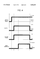
- FIG. 4 is a timing diagram relating to an embodiment of the present invention.
- FIG. 5 is a diagram showing a more detailed circuit configuration for an embodiment of the present invention.
- FIG. 6 is an illustration of alternate embodiment of the invention in which the device according to the invention monitors incoming calls to a plurality of extensions.
- FIG. 7 is a block diagram of still another embodiment of the present invention in which both incoming and outgoing calls are monitored.
- FIG. 8 is a partial flow-chart showing the operation of yet another embodiment of the present invention.
- FIG. 1 is a block diagram showing a call waiting cancellation (CWC) device according to the invention.
- a plurality of extensions 2 are provided at a remote location from a telephone switching central office 1 and are connected thereto via a standard telephone line, for example, a twisted pair 5.
- An additional extension shown as telecommunication device 4 is connected in series with the telephone line 5 through a CWC device 3.
- the telecommunication device 4 represents any device which transmits or receives communications signals over a telephone line, including a telephone instrument, an answering machine, a facsimile, a meter interface communication circuit or alarm system, a video or message terminal, a transaction terminal, a facsimile device, or any other device utilizing a modem for data transmission.
- the call waiting cancellation device 3 operates in two modes. In a first mode, calls are initiated by the telecommunication device 4 or are received (or initiated) by other extensions 2. In this mode, the call waiting cancellation device is passive. Thus, when an outgoing call is made from the telecommunication device 4, the call waiting cancellation device 3 has no effect on the telephone line or on the features provided from the central office 1. Similarly, the call waiting cancellation device has no effect when other extensions 2 are used exclusively of the telecommunications device 4 to place or receive a call.
- a second mode calls are received by the telecommunications device 4. That is, in response to a ring signal received from the central office 1 over the telephone line 5, the telecommunications device 4 goes off-hook, thereby receiving the incoming call. Under these conditions, the CWC device 3 temporarily disconnects the terminal 4 from the telephone line 5 and then transmits an appropriate cancellation code to the central office 1 to cancel subsequent call waiting signals during the call. If the system utilizes tone dialing, a *70 code is transmitted; if the system utilizes pulse dialing, an 1170 code is transmitted.
- FIG. 2 A more detailed organization of the preferred embodiment of the invention is illustrated in the block diagram of FIG. 2 in which a CWC device 10 is shown in dashed lines.
- the CWC device 10 is attached in series to a facsimile machine 90. While reference is made in the following discussion of this embodiment to a facsimile machine 90, any telecommunication device may be advantageously connected to the CWC device.
- the CWC device 10 is additionally connected to a standard telephone line 95.
- the CWC device 10 in this example is also connected in parallel to a second extension 15, shown as a telephone instrument 15.
- the CWC device 10 comprises a switch 20 and an off-hook detector circuit 30 which connected in series with the facsimile machine 90 and the telephone line 95 from the central office. Both the switch 20 and the off-hook detector circuit 30 are operatively coupled to a controller 40. Also connected to the telephone line 95 are a ring detector circuit 70 and a signal generator 80. Both of these circuits are connected to the controller 40. Also provided is a tone/pulse switch 85 which indicates the type of service subscribed to. As shown, the controller 40 is connected to both a power supply 60 and an auxiliary line power circuit 50. The power supply 60 provides power to the CWC device from either a rectified AC supply or from a DC supply, such as a battery, in accordance with conventional techniques.
- a ringing signal passes through the switch 20 (maintained in a closed position) and through the off-hook detector circuit 30 to the facsimile machine 90.
- the incoming ringing signal also passes through the ring detector circuit 70.
- the ring detector circuit 70 On detecting a ringing signal, the ring detector circuit 70 notifies the controller 40 of an incoming call. Thereupon, the controller 40 instructs the off-hook detector 30 to monitor the line 97 going to the facsimile machine 90.
- Step F101 begins with the CWC device 10 operating in the first mode referred to above.
- the controller 40 monitors the incoming line 95 at step F102 through ring detector circuit 70. As long as no ring is detected, the CWC device 10 remains in the first mode. However, if a ring is detected, the controller then, at step F103, determines through off-hook detector circuit, 30 whether the device connected to the outgoing line 97 is off-hook. If not, the CWC device 10 again remains in the first mode.
- the extension telephone 15 is connected in parallel to the CWC device 10.
- the off-hook detector 30 will not detect an off-hook condition for the device connected to the outgoing line 97.
- the result at step F103 will be a "no" when the extension goes off-hook, and therefore the controller will not activate subsequent call waiting cancellation sequences represented in FIG. 3 by steps F104 to F108.
- the controller 40 determines that the device connected to the outgoing line 97 has gone off-hook in response to an incoming call, at step F104, the controller 40 instructs the switch 20 to disconnect the connection between the incoming line 95 and the outgoing line 97. Because many devices, such as facsimile machines, are designed to automatically terminate transmission or reception when a disconnect is detected, at step F105, the controller optionally may instruct the auxiliary line power circuit 50 to provide a nominal tip-ring voltage of, for example, 5 V or more, to the outgoing line 97. In the example shown in FIG. 2, this prevents the facsimile machine 90 from terminating the call.
- the controller 40 instructs the signal generator 80 to send a hook flash signal, and then a call waiting cancellation code to the central office. If the tone/pulse switch 85 indicates that a pulse dialing is used, the code "1170" is transmitted. On the other hand, if the tone/pulse switch 85 indicates that tone dialing is used, the code "*70" is transmitted.
- the controller 40 then disables the auxiliary line power provided to the outgoing line 97. Approximately simultaneously, the controller 40 also controls the switch 20 to return to a closed state to reconnect the incoming line 95 with the outgoing line 97 to the facsimile machine 90 (step F107).
- the controller 40 then waits for the call to terminate.
- the controller 40 could be suitably programmed to permit an interrupt from the off-hook detector 30 which indicates that the outgoing line 97 has returned on-hook.
- the CWC device is returned to the first mode at step F101 and the sequence resumes.
- FIG. 4 generally shows the time sequence of the actions taken by the CWC device according to the invention in an idealized plot.
- the overall time dependent action of the CWC device begins after the outgoing line to a telecommunication device connected to the CWC device is taken off-hook (for example, after a "yes" result is detected at step F103).
- the device connected to the CWC device takes the line to the central office off-hook.
- the switch within the CWC device which controls the connection between the incoming line from the central office and the outgoing line to the connected device switches from a closed position to an open position, thereby disconnecting the outgoing line from the central office.
- auxiliary line power is supplied to the outgoing line to ensure that the connected device does not automatically disconnect.
- the signal generator within the CWC device generates a cancellation code which is provided to the line to the central office.
- the signal generator's transmission terminates, and the switch is closed and the auxiliary power is discontinued.
- the interval (t 2 -t 2 ) should not be too short.
- this time interval should not exceed approximately 2 seconds, otherwise, the facsimile machine may begin transmission of data signals before the call is resumed.
- the interval (t 2 -t 1 ) should be approximately 500 ms.
- the disconnection of the incoming line and the outgoing line to the connected device is equivalent to an on-hook condition.
- the time between the switch opening at t 2 and the time at which signal generator opens the line at t 3 a hookflash signal is transmitted to the central office. Accordingly, the hook flash signal precedes the generation of a call waiting cancellation code. Care must be exercised to ensure that the hook flash signal is interpreted correctly by the central office. If this action is too fast, the central office will not interpret the signals as a hook flash. On the other hand, if the momentary on-hook condition is too long, the central office will disconnect the line. Generally, the momentary on-hook condition interval t 3 -t 2 should be between 300 and 1100 ms.
- the signal generator within the CWC device sends the appropriate call waiting cancellation code.
- the tone code is "*70" and the pulse signal is 1170.
- the appropriate one of these signals should be sent within 200 to 500 ms in order for the central office to terminate the call waiting service for the duration of the call.
- the overall time (t 4 -t 1 ) for the connected device to take the incoming line off-hook and then for the CWC device to return the line back to the connected device is approximately 1.5 seconds.
- the connected device is a facsimile machine, it will typically be attempting to establish a connection with the calling party by transmitting the appropriate signals.
- the delay of 1.5 seconds will normally not be long enough to cause the facsimile machine to determine that an error has occurred or to disconnect from the line.
- FIG. 5 is a circuit diagram illustrating a preferred embodiment of a CWC device 300 according to the invention. Shown in dashed lines are the main components of the CWC device 300. These include a ring detector circuit 320, a controller circuit 340, an off-hook detector circuit 360, a signal generator circuit 380, and a switch/auxiliary power circuit 400.
- the LINE IN from a central office is coupled to the ring detect circuit 320 and to the off-hook detector circuit 360 via a fuse 302.
- the LINE OUT to a telecommunication device connected to the CWC device 300 is coupled to the switch/auxiliary power circuit 400.
- the switch/auxiliary power circuit 400 selectively couples the line out to either the LINE IN or to a +13 V power supply via a resistor 408 in accordance with a logic Signal supplied from the controller circuit 340.
- the ring detector circuit 320 comprises a capacitor 322 connected in series with two zener diodes 324 and 326, a resistor 332 coupled in series with the fuse 302, and an ac optocouple 330 (in this example, a Motorola optocouple, part no. H11AA2) which provides a logic signal to the controller circuit 340. Also provided across the line in is a diode 328. Arranged as shown, this circuit detects a change in voltage across the LINE IN which occurs when a ring signal is transmitted from the central office. The optocouple 330 produces a logic signal in response to a detected ring signal.
- the off-hook detect circuit 360 is coupled between the LINE IN and the LINE OUT, and detects whether a point therebetween is on-hook or off-hook.
- the LINE IN is coupled directly to one input of a second ac optocouple 368.
- This line is provided to the switch circuit 400 via a resistor 362.
- the same line is coupled via resistor 364 and capacitor 366 (arranged in parallel) to a second input to the optocouple 368.
- the optocouple 368 detects a change in voltage on the line connecting the LINE IN to the LINE OUT. This change in voltage indicates whether the line is off-hook or on-hook.
- the optocouple 368 produces a corresponding logic signal which is output to the controller circuit 340 on the signal line 370 labelled "OFF-HOOK.”
- the switch/auxiliary power circuit 400 comprises a dual relay 402 which contains ganged switches 402a and 402b.
- the switches 402a and 402b selectively couple the LINE OUT to either the LINE IN or a +13 V auxiliary power source via a resistor 408.
- the relay is controlled according to the on-off state of a transistor 404, which operates in response to a logic signal supplied via a resistor 406 from the controller circuit 340.
- the signal generator circuit 380 includes a DTMF generator component 396.
- a DTMF generator manufactured by SGS Thomson, part number EFG 7189 is used.
- the DTMF generator 396 is coupled to a 3.6 MHz crystal oscillator 398.
- the DTMF generator 396 receives logic signals comprising an ACK signal and a four bit signal (DTMF 0-3) indicative of the tone to be produced by the DTMF generator 396.
- the DTMF generator 396 produces an appropriate cancellation code which is provided to the LINE IN via a resistor 394, a capacitor 390, transistors 384 and 388 and a diode bridge rectifier 382 (in this example, part no. DF04 by Diodes Inc.).
- the base of transistor 388 is further coupled to an input of the controller circuit 340 via a resistor 392.
- the main component of the controller circuit 340 consists of microcontroller 356.
- a Microchip PIC16C54-X microcontroller is utilized to provide appropriate DTMF logic signals to the DTMF generator 396 in response to the off-hook and ring-detect signals received respectively from the off-hook detection circuit 360 and the ring detector circuit 320.
- the controller 356 is operatively coupled to a 4 MHz crystal oscillator 352.
- a reset circuit is coupled to a MCLR input to reset the microcontroller in the event of a system failure. As shown, the reset circuit comprises three resistors 342, 344 and 348 and a transistor 346.
- the microcontroller 356 is suitably programmed according to manufacture specifications to implement, for example, the sequence of steps described with reference to FIG. 3. In this way, upon detection of a ring signal and a subsequent off-hook condition, the controller circuit 340 outputs a series of control signal causing the generator circuit 380 to produce an appropriate call waiting cancellation code.
- FIG. 6 shows another embodiment of the invention in which identical elements are referred to with the same reference numerals as FIG. 2.
- a CWC device 100 according to the invention is provided with several ports (typically standard telephone line jacks) so that a plurality of telecommunication devices can be attached in parallel.
- any telephone extension 110, 112, 114 connected respectively to ports 102, 104, 106 of the CWC device 100 go off-hook in response to an incoming call
- the CWC device 100 will send a call waiting cancellation signal in response to an off-hook detection signal generated from the detector circuit 30.
- FIG. 7 illustrates a third embodiment of the invention in which a CWC device 200 sends a call waiting cancellation signal regardless of whether an incoming call is being received or an outgoing call is being placed.
- no ring detector circuit is utilized. Accordingly, a call waiting cancellation signal is transmitted whenever a connected device, such as a facsimile machine 90, goes off-hook.
- FIG. 8 is a partial flow-chart of still another embodiment of the invention.
- This embodiment may be advantageously utilized in areas in which the telephone switching central office periodically resets the call waiting features at a predetermined interval. In such areas, there is the risk that the central office will reset call waiting during a call even though a call waiting cancellation code was initially sent.
- the controller provided in the CWC device is programmed to periodically resend the appropriate cancellation code at intervals equal to or less than the predetermined interval at which the call waiting feature would otherwise be reset.
- the controller is programmed to wait at a step F109 a time of N seconds which is equal or less than the predetermined interval which occurs subsequent to the initial transmission of the call waiting cancellation code. This process continues until disconnection of the call is detected.
- the invention may advantageously be integrated into several different types of telecommunication devices or add-on modules to telecommunication devices.
- Such devices include distinctive ringing selection devices, facsimile machines, answering machines, telephone sets, computer systems, telephone add-on devices, meter interface communication circuits or alarm systems, and other devices using modems. Examples of such applications of the invention are now described.
- distinctive ringing selection devices utilize a microprocessor based system to allow an effective way of sharing one line among several answering devices.
- Common units are the "Ring Selector” by Aastra Corporation, “ComShare” devices by Command Communications, Inc. and “Ring Director” by Lynx Automation, Inc. These devices work with a telephone company's distinctive ringing services such as those known by trade names such as RingMaster, SmartRing, Priority Ring, RingMate, Personalized Ring, Ident-A-Ring, Ident-A-Call and others. This service provides up to four numbers on a single line. Different ringing sequences or ring cadences are associated with each telephone number.
- a distinctive ringing selection device With a distinctive ringing selection device, only the selected ringing sequence will be allowed to pass through. As such, if a facsimile machine is connected to a distinctive ringing selection device, it will only be activated if an incoming call is a facsimile data transmission.
- a CWC device may be incorporated within the same housing as the distinctive ringing selection device.
- a common microprocessor provides the call waiting cancellation functions described above with reference to controller 40 and also operates to provide switching among different devices connected to the same line.
- Other common components can provide the functional aspects of the distinctive ringer units and the CWC device.
- the CWC device can comprise a stand-alone unit incorporated under the same housing as the conventional device. Alternatively, it can be redesigned to take advantage of using the same microcontroller as the controller for the device. In such a situation, no off-hook detection circuit or switch is required.
- a microcontroller is programmed to temporarily put the line on hold with a hook flash signal, and then to generate a call waiting cancellation code as described above. After the code is generated, the line is then connected back to the conventional components of the terminal. Once reconnection is established, the answering machine can begin its introductory message. Similarly, a facsimile machine or modem may operate to transmit its protocol tones for initiation of data transmission once reconnection is established.
- the CWC device according to the invention may be advantageously used even with voice communication applications.
- the user typically wants the call waiting feature active, in certain situations, it is desirable to render call waiting inactive.
- users of particular extensions may dislike the interruption which takes place from a second call.
- Such extensions can be coupled to the CWC device so that call waiting is disabled for incoming calls received by those extensions.
- the invention can be implemented with, for example, a manually operated button that would initiate a hook flash and then a call waiting cancellation signal.
- CWC software could comprise part of the overall software used in a modem or a facsimile machine to answer an incoming call.
- the software would open the line when ringing is detected according to conventional techniques, but then also send a hook flash signal and a call waiting cancellation signal before data protocol signals are transmitted.
- Such a software implementation could be incorporated into the code provided in a facsimile or modem computer card.
- this software implementation can be code-embedded in existing communications software, such as Winfax by Delina of Ontario, Canada, or ProComm Plus by Datastorm of Columbia, Mo., or it can comprise add-on software.
- a CWC device according to the invention can also be incorporated as part of other telephone add-on devices, such as caller identifier modules and call waiting display modules.
- This automatic cancellation system can be extended to other network features such as busy call return (also known as "call again”) or other network features that send signals that may interrupt ongoing data transmission.
- PBX private branch exchange
Abstract
Description
Claims (22)
Priority Applications (1)
| Application Number | Priority Date | Filing Date | Title |
|---|---|---|---|
| US08/455,517 US5546451A (en) | 1995-05-31 | 1995-05-31 | Call waiting cancellation device |
Applications Claiming Priority (1)
| Application Number | Priority Date | Filing Date | Title |
|---|---|---|---|
| US08/455,517 US5546451A (en) | 1995-05-31 | 1995-05-31 | Call waiting cancellation device |
Publications (1)
| Publication Number | Publication Date |
|---|---|
| US5546451A true US5546451A (en) | 1996-08-13 |
Family
ID=23809133
Family Applications (1)
| Application Number | Title | Priority Date | Filing Date |
|---|---|---|---|
| US08/455,517 Expired - Lifetime US5546451A (en) | 1995-05-31 | 1995-05-31 | Call waiting cancellation device |
Country Status (1)
| Country | Link |
|---|---|
| US (1) | US5546451A (en) |
Cited By (19)
| Publication number | Priority date | Publication date | Assignee | Title |
|---|---|---|---|---|
| GB2303272A (en) * | 1995-07-10 | 1997-02-12 | Hong Kong Telecommunications L | Telephone network |
| US5737094A (en) * | 1995-08-09 | 1998-04-07 | Ricoh Company, Ltd. | Secure fax adapter method and apparatus |
| US5835239A (en) * | 1995-01-16 | 1998-11-10 | Samsung Electronics Co., Ltd. | Facsimile apparatus having access function to a plurality of telephone lines and access method |
| WO1999017519A2 (en) * | 1997-09-26 | 1999-04-08 | Telefonaktiebolaget Lm Ericsson (Publ) | A method and an arrangement relating to functions in a telecommunication network |
| EP0944285A2 (en) * | 1998-03-20 | 1999-09-22 | Deutsche Telekom AG | Apparatus and method for automatically activating and deactivating services |
| US6289092B1 (en) * | 1997-05-01 | 2001-09-11 | Fujitsu Limited | Method and apparatus for selectively suspending or activating a call waiting service |
| US6496283B1 (en) * | 1998-03-30 | 2002-12-17 | Brother Kogyo Kabushiki Kaisha | Communication device |
| US6546091B1 (en) * | 1998-08-28 | 2003-04-08 | Thomson Licensing S.A. | Automatic detection of phone system settings for dial-up modem connections |
| US20040120495A1 (en) * | 2002-12-24 | 2004-06-24 | Rice Steven A. | Method of disabling call-waiting before receiving incoming fax |
| US20040264681A1 (en) * | 2003-06-30 | 2004-12-30 | Silver Edward Michael | Caller controlled network-based timed ring suppression |
| US20040266490A1 (en) * | 2003-06-30 | 2004-12-30 | Silver Edward Michael | Timed ring suppressor |
| US20050195953A1 (en) * | 2004-03-05 | 2005-09-08 | Rice Steven A. | Method for carrying out predetermined actions by a receiving telecom device using an answer prefix |
| US20050271197A1 (en) * | 2004-06-03 | 2005-12-08 | Mcclure William C | Apparatus and method for CNG detection with call waiting |
| US20070121921A1 (en) * | 2003-06-30 | 2007-05-31 | Silver Edward M | Network-based timed ring suppression |
| US7352854B1 (en) * | 2003-09-29 | 2008-04-01 | At&T Delaware Intellectual Property, Inc. | Call waiting suppression |
| US7443967B1 (en) | 2003-09-29 | 2008-10-28 | At&T Intellectual Property I, L.P. | Second communication during ring suppression |
| CN100583927C (en) * | 2005-10-18 | 2010-01-20 | 华为技术有限公司 | Method for communication terminal to select calls in call waiting |
| WO2010145622A1 (en) * | 2009-10-27 | 2010-12-23 | 中兴通讯股份有限公司 | Method for processing flash-hook service and application server thereof |
| CN101155398B (en) * | 2006-09-25 | 2011-01-05 | 华为技术有限公司 | Call control method and communication system |
Citations (12)
| Publication number | Priority date | Publication date | Assignee | Title |
|---|---|---|---|---|
| US4661975A (en) * | 1985-03-13 | 1987-04-28 | Bell Communications Research, Inc. | Enhanced call-waiting service |
| JPS63250256A (en) * | 1987-04-06 | 1988-10-18 | Hitachi Ltd | Call waiting service system |
| US4852151A (en) * | 1988-02-24 | 1989-07-25 | Hayes Microcomputer Products, Inc. | Modem with call waiting |
| US4995074A (en) * | 1989-04-03 | 1991-02-19 | Goldman Bruce J | Switched line modem interface system |
| JPH0491546A (en) * | 1990-08-06 | 1992-03-25 | Fujitsu Ltd | Call waiting service controlling system |
| US5287401A (en) * | 1993-03-15 | 1994-02-15 | Intel Corporation | Apparatus and method for a modem for detecting a call waiting signal |
| US5327488A (en) * | 1992-03-20 | 1994-07-05 | At&T Bell Laboratories | Remotely initiated telemetry calling system |
| US5337351A (en) * | 1992-02-28 | 1994-08-09 | Nec America, Inc. | Feature interaction arbitrator |
| US5425092A (en) * | 1992-12-14 | 1995-06-13 | Mitel Corporation | Delayed cancel call waiting |
| US5432616A (en) * | 1991-01-17 | 1995-07-11 | Fuji Xerox Co., Ltd. | Data communication apparatus for notification of the receipt of a call waiting signal |
| US5432845A (en) * | 1992-12-21 | 1995-07-11 | At&T Corp. | Post answer telephone call redirection or rerouting |
| US5448631A (en) * | 1992-10-13 | 1995-09-05 | U S West Advanced Technologies, Inc. | Apparatus for handling features in a telephone network |
-
1995
- 1995-05-31 US US08/455,517 patent/US5546451A/en not_active Expired - Lifetime
Patent Citations (12)
| Publication number | Priority date | Publication date | Assignee | Title |
|---|---|---|---|---|
| US4661975A (en) * | 1985-03-13 | 1987-04-28 | Bell Communications Research, Inc. | Enhanced call-waiting service |
| JPS63250256A (en) * | 1987-04-06 | 1988-10-18 | Hitachi Ltd | Call waiting service system |
| US4852151A (en) * | 1988-02-24 | 1989-07-25 | Hayes Microcomputer Products, Inc. | Modem with call waiting |
| US4995074A (en) * | 1989-04-03 | 1991-02-19 | Goldman Bruce J | Switched line modem interface system |
| JPH0491546A (en) * | 1990-08-06 | 1992-03-25 | Fujitsu Ltd | Call waiting service controlling system |
| US5432616A (en) * | 1991-01-17 | 1995-07-11 | Fuji Xerox Co., Ltd. | Data communication apparatus for notification of the receipt of a call waiting signal |
| US5337351A (en) * | 1992-02-28 | 1994-08-09 | Nec America, Inc. | Feature interaction arbitrator |
| US5327488A (en) * | 1992-03-20 | 1994-07-05 | At&T Bell Laboratories | Remotely initiated telemetry calling system |
| US5448631A (en) * | 1992-10-13 | 1995-09-05 | U S West Advanced Technologies, Inc. | Apparatus for handling features in a telephone network |
| US5425092A (en) * | 1992-12-14 | 1995-06-13 | Mitel Corporation | Delayed cancel call waiting |
| US5432845A (en) * | 1992-12-21 | 1995-07-11 | At&T Corp. | Post answer telephone call redirection or rerouting |
| US5287401A (en) * | 1993-03-15 | 1994-02-15 | Intel Corporation | Apparatus and method for a modem for detecting a call waiting signal |
Cited By (44)
| Publication number | Priority date | Publication date | Assignee | Title |
|---|---|---|---|---|
| US5835239A (en) * | 1995-01-16 | 1998-11-10 | Samsung Electronics Co., Ltd. | Facsimile apparatus having access function to a plurality of telephone lines and access method |
| GB2303272A (en) * | 1995-07-10 | 1997-02-12 | Hong Kong Telecommunications L | Telephone network |
| GB2303272B (en) * | 1995-07-10 | 2000-02-23 | Hong Kong Telecommunications L | Telephone network |
| US6008909A (en) * | 1995-08-09 | 1999-12-28 | Ricoh Company, Ltd. | Secure fax adapter method and apparatus |
| US5737094A (en) * | 1995-08-09 | 1998-04-07 | Ricoh Company, Ltd. | Secure fax adapter method and apparatus |
| US6289092B1 (en) * | 1997-05-01 | 2001-09-11 | Fujitsu Limited | Method and apparatus for selectively suspending or activating a call waiting service |
| GB2344968A (en) * | 1997-09-26 | 2000-06-21 | Ericsson Telefon Ab L M | A method and an arrangement relating to functions in a telecommunication network |
| WO1999017519A3 (en) * | 1997-09-26 | 1999-06-17 | Ericsson Telefon Ab L M | A method and an arrangement relating to functions in a telecommunication network |
| GB2344968B (en) * | 1997-09-26 | 2002-08-28 | Ericsson Telefon Ab L M | A method and an arrangement relating to functions in a telecommunication network |
| AU752742B2 (en) * | 1997-09-26 | 2002-09-26 | Telefonaktiebolaget Lm Ericsson (Publ) | A method and an arrangement relating to functions in a telecommunication network |
| WO1999017519A2 (en) * | 1997-09-26 | 1999-04-08 | Telefonaktiebolaget Lm Ericsson (Publ) | A method and an arrangement relating to functions in a telecommunication network |
| EP0944285A2 (en) * | 1998-03-20 | 1999-09-22 | Deutsche Telekom AG | Apparatus and method for automatically activating and deactivating services |
| DE19812283B4 (en) * | 1998-03-20 | 2005-11-10 | Deutsche Telekom Ag | Device for automatic deactivation of features in an exchange |
| EP0944285A3 (en) * | 1998-03-20 | 2006-01-04 | Deutsche Telekom AG | Apparatus and method for automatically activating and deactivating services |
| US6496283B1 (en) * | 1998-03-30 | 2002-12-17 | Brother Kogyo Kabushiki Kaisha | Communication device |
| US6546091B1 (en) * | 1998-08-28 | 2003-04-08 | Thomson Licensing S.A. | Automatic detection of phone system settings for dial-up modem connections |
| US20040120495A1 (en) * | 2002-12-24 | 2004-06-24 | Rice Steven A. | Method of disabling call-waiting before receiving incoming fax |
| US7660610B2 (en) | 2003-06-30 | 2010-02-09 | At&T Intellectual Property I, L. P. | Methods, systems, and products for timed ring suppression |
| US7529564B2 (en) | 2003-06-30 | 2009-05-05 | At&T Intellectual Property I, L.P. | Timed ring suppressor |
| US9426280B2 (en) | 2003-06-30 | 2016-08-23 | At&T Intellectual Property I, L.P. | Network-based timed ring suppression |
| US20040266490A1 (en) * | 2003-06-30 | 2004-12-30 | Silver Edward Michael | Timed ring suppressor |
| US7113586B2 (en) | 2003-06-30 | 2006-09-26 | Edward Michael Silver | Caller controlled network-based timed ring suppression |
| US8548158B2 (en) | 2003-06-30 | 2013-10-01 | At&T Intellectual Property I, L. P. | Network based timed ring suppression |
| US20070121921A1 (en) * | 2003-06-30 | 2007-05-31 | Silver Edward M | Network-based timed ring suppression |
| US20070121920A1 (en) * | 2003-06-30 | 2007-05-31 | Silver Edward M | Caller controlled network-based timed ring suppression |
| US7239693B2 (en) | 2003-06-30 | 2007-07-03 | Bellsouth Intellectual Property Corporation | Network-based timed ring suppression |
| US7840238B2 (en) | 2003-06-30 | 2010-11-23 | At&T Intellectual Property I, L.P. | Methods, systems, and products for timed ring suppression |
| US20100098239A1 (en) * | 2003-06-30 | 2010-04-22 | Edward Michael Silver | Methods, Systems, and Products for Timed Ring Suppression |
| US20040264681A1 (en) * | 2003-06-30 | 2004-12-30 | Silver Edward Michael | Caller controlled network-based timed ring suppression |
| US20090207989A1 (en) * | 2003-06-30 | 2009-08-20 | Edward Michael Silver | Methods, Systems, and Products for Timed Ring Suppression |
| US8619954B2 (en) | 2003-09-29 | 2013-12-31 | At&T Intellectual Property I, L.P. | Methods, systems, and products for ring suppression |
| US9936069B2 (en) | 2003-09-29 | 2018-04-03 | At&T Intellectual Property I, L.P. | Methods, systems, and products for suppression of alerts |
| US7443967B1 (en) | 2003-09-29 | 2008-10-28 | At&T Intellectual Property I, L.P. | Second communication during ring suppression |
| US7352854B1 (en) * | 2003-09-29 | 2008-04-01 | At&T Delaware Intellectual Property, Inc. | Call waiting suppression |
| US20090052652A1 (en) * | 2003-09-29 | 2009-02-26 | Edward Michael Silver | Methods, Systems, and Products for Ring Suppression |
| US9525774B2 (en) | 2003-09-29 | 2016-12-20 | At&T Intellectual Property I, L.P. | Methods, systems, and products for suppression of alerts |
| US9137382B2 (en) | 2003-09-29 | 2015-09-15 | At&T Intellectual Property I, L.P. | Methods, systems, and products for suppression of alerts |
| US20050195953A1 (en) * | 2004-03-05 | 2005-09-08 | Rice Steven A. | Method for carrying out predetermined actions by a receiving telecom device using an answer prefix |
| US7359500B2 (en) * | 2004-03-05 | 2008-04-15 | Lexmark International Inc. | Method for carrying out predetermined actions by a receiving telecom device using an answer prefix |
| US7184537B2 (en) * | 2004-06-03 | 2007-02-27 | Command Communications, Inc. | Apparatus and method for CNG detection with call waiting |
| US20050271197A1 (en) * | 2004-06-03 | 2005-12-08 | Mcclure William C | Apparatus and method for CNG detection with call waiting |
| CN100583927C (en) * | 2005-10-18 | 2010-01-20 | 华为技术有限公司 | Method for communication terminal to select calls in call waiting |
| CN101155398B (en) * | 2006-09-25 | 2011-01-05 | 华为技术有限公司 | Call control method and communication system |
| WO2010145622A1 (en) * | 2009-10-27 | 2010-12-23 | 中兴通讯股份有限公司 | Method for processing flash-hook service and application server thereof |
Similar Documents
| Publication | Publication Date | Title |
|---|---|---|
| US5546451A (en) | Call waiting cancellation device | |
| US7139585B2 (en) | Wireless communication apparatus and system | |
| KR950008865B1 (en) | Interface control device | |
| US5812646A (en) | Switching controller with supervisory mode for communication terminals | |
| JPH0821992B2 (en) | Multi-terminal communication controller | |
| JP3091065B2 (en) | Communication device for data transmission by no ringing | |
| JP2961849B2 (en) | Private branch exchange system | |
| JP2680587B2 (en) | Communication device | |
| JP2633253B2 (en) | Telephone terminal device | |
| JP2982686B2 (en) | Private branch exchange | |
| JP3133703B2 (en) | Modem system | |
| JP2664175B2 (en) | Communications system | |
| KR100479418B1 (en) | Message transfer device of answering machine and method | |
| JPH0738661A (en) | Telephone switchboard | |
| JP3249802B2 (en) | No-ringing communication equipment | |
| JP2543060B2 (en) | Telephone exchange | |
| JP3349487B2 (en) | No ringing communication device | |
| JP3668903B2 (en) | Automatic loop starting method and apparatus | |
| JP2802328B2 (en) | Automatic selection receiver | |
| JPS63248295A (en) | Communication equipment | |
| JP3688893B2 (en) | Button telephone with power failure function | |
| JP3249220B2 (en) | Facsimile machine with built-in telephone | |
| JPH01233870A (en) | Telephone set | |
| JP2001036659A (en) | Telephone set connector | |
| JPH05160920A (en) | Communication control unit |
Legal Events
| Date | Code | Title | Description |
|---|---|---|---|
| AS | Assignment |
Owner name: AASTRA CORPORATION, CANADA Free format text: ASSIGNMENT OF ASSIGNORS INTEREST;ASSIGNOR:SHEN, ANTHONY P.;REEL/FRAME:007531/0728 Effective date: 19950526 |
|
| AS | Assignment |
Owner name: AASTRA TECHNOLOGIES INC., CANADA Free format text: ASSIGNMENT OF ASSIGNORS INTEREST;ASSIGNOR:AASTRA CORPORATION;REEL/FRAME:008004/0059 Effective date: 19960625 |
|
| STCF | Information on status: patent grant |
Free format text: PATENTED CASE |
|
| FEPP | Fee payment procedure |
Free format text: PAYOR NUMBER ASSIGNED (ORIGINAL EVENT CODE: ASPN); ENTITY STATUS OF PATENT OWNER: LARGE ENTITY |
|
| FPAY | Fee payment |
Year of fee payment: 4 |
|
| FEPP | Fee payment procedure |
Free format text: PAT HOLDER NO LONGER CLAIMS SMALL ENTITY STATUS, ENTITY STATUS SET TO UNDISCOUNTED (ORIGINAL EVENT CODE: STOL); ENTITY STATUS OF PATENT OWNER: LARGE ENTITY |
|
| REFU | Refund |
Free format text: REFUND - PAYMENT OF MAINTENANCE FEE, 8TH YR, SMALL ENTITY (ORIGINAL EVENT CODE: R2552); ENTITY STATUS OF PATENT OWNER: LARGE ENTITY |
|
| FPAY | Fee payment |
Year of fee payment: 8 |
|
| FPAY | Fee payment |
Year of fee payment: 12 |
|
| REMI | Maintenance fee reminder mailed |