US5328540A - Mechanized lay up assembly line for composite structures - Google Patents
Mechanized lay up assembly line for composite structures Download PDFInfo
- Publication number
- US5328540A US5328540A US07/847,518 US84751892A US5328540A US 5328540 A US5328540 A US 5328540A US 84751892 A US84751892 A US 84751892A US 5328540 A US5328540 A US 5328540A
- Authority
- US
- United States
- Prior art keywords
- rollers
- tool
- vacuum
- working surface
- diaphragm
- Prior art date
- Legal status (The legal status is an assumption and is not a legal conclusion. Google has not performed a legal analysis and makes no representation as to the accuracy of the status listed.)
- Expired - Lifetime
Links
Images


Classifications
-
- B—PERFORMING OPERATIONS; TRANSPORTING
- B29—WORKING OF PLASTICS; WORKING OF SUBSTANCES IN A PLASTIC STATE IN GENERAL
- B29C—SHAPING OR JOINING OF PLASTICS; SHAPING OF MATERIAL IN A PLASTIC STATE, NOT OTHERWISE PROVIDED FOR; AFTER-TREATMENT OF THE SHAPED PRODUCTS, e.g. REPAIRING
- B29C70/00—Shaping composites, i.e. plastics material comprising reinforcements, fillers or preformed parts, e.g. inserts
- B29C70/04—Shaping composites, i.e. plastics material comprising reinforcements, fillers or preformed parts, e.g. inserts comprising reinforcements only, e.g. self-reinforcing plastics
- B29C70/28—Shaping operations therefor
- B29C70/30—Shaping by lay-up, i.e. applying fibres, tape or broadsheet on a mould, former or core; Shaping by spray-up, i.e. spraying of fibres on a mould, former or core
-
- B—PERFORMING OPERATIONS; TRANSPORTING
- B29—WORKING OF PLASTICS; WORKING OF SUBSTANCES IN A PLASTIC STATE IN GENERAL
- B29C—SHAPING OR JOINING OF PLASTICS; SHAPING OF MATERIAL IN A PLASTIC STATE, NOT OTHERWISE PROVIDED FOR; AFTER-TREATMENT OF THE SHAPED PRODUCTS, e.g. REPAIRING
- B29C33/00—Moulds or cores; Details thereof or accessories therefor
- B29C33/34—Moulds or cores; Details thereof or accessories therefor movable, e.g. to or from the moulding station
-
- B—PERFORMING OPERATIONS; TRANSPORTING
- B29—WORKING OF PLASTICS; WORKING OF SUBSTANCES IN A PLASTIC STATE IN GENERAL
- B29C—SHAPING OR JOINING OF PLASTICS; SHAPING OF MATERIAL IN A PLASTIC STATE, NOT OTHERWISE PROVIDED FOR; AFTER-TREATMENT OF THE SHAPED PRODUCTS, e.g. REPAIRING
- B29C70/00—Shaping composites, i.e. plastics material comprising reinforcements, fillers or preformed parts, e.g. inserts
- B29C70/04—Shaping composites, i.e. plastics material comprising reinforcements, fillers or preformed parts, e.g. inserts comprising reinforcements only, e.g. self-reinforcing plastics
- B29C70/28—Shaping operations therefor
- B29C70/40—Shaping or impregnating by compression not applied
- B29C70/42—Shaping or impregnating by compression not applied for producing articles of definite length, i.e. discrete articles
- B29C70/44—Shaping or impregnating by compression not applied for producing articles of definite length, i.e. discrete articles using isostatic pressure, e.g. pressure difference-moulding, vacuum bag-moulding, autoclave-moulding or expanding rubber-moulding
-
- B—PERFORMING OPERATIONS; TRANSPORTING
- B29—WORKING OF PLASTICS; WORKING OF SUBSTANCES IN A PLASTIC STATE IN GENERAL
- B29C—SHAPING OR JOINING OF PLASTICS; SHAPING OF MATERIAL IN A PLASTIC STATE, NOT OTHERWISE PROVIDED FOR; AFTER-TREATMENT OF THE SHAPED PRODUCTS, e.g. REPAIRING
- B29C37/00—Component parts, details, accessories or auxiliary operations, not covered by group B29C33/00 or B29C35/00
- B29C37/006—Degassing moulding material or draining off gas during moulding
-
- Y—GENERAL TAGGING OF NEW TECHNOLOGICAL DEVELOPMENTS; GENERAL TAGGING OF CROSS-SECTIONAL TECHNOLOGIES SPANNING OVER SEVERAL SECTIONS OF THE IPC; TECHNICAL SUBJECTS COVERED BY FORMER USPC CROSS-REFERENCE ART COLLECTIONS [XRACs] AND DIGESTS
- Y10—TECHNICAL SUBJECTS COVERED BY FORMER USPC
- Y10T—TECHNICAL SUBJECTS COVERED BY FORMER US CLASSIFICATION
- Y10T156/00—Adhesive bonding and miscellaneous chemical manufacture
- Y10T156/17—Surface bonding means and/or assemblymeans with work feeding or handling means
- Y10T156/1702—For plural parts or plural areas of single part
- Y10T156/1744—Means bringing discrete articles into assembled relationship
- Y10T156/1751—At least three articles
- Y10T156/1761—Stacked serially
Definitions
- This invention is directed to a mechanized lay up assembly line utilized for lay up and debulking of composite materials on lay up tools.
- composite parts are being increasingly used as structural components in a variety of articles including air craft.
- Typical composite part materials include glass or graphite fibers that are embedded in resins such as epoxy, phenolic or bismaleimide resins. Generally the fiber and resin is "laid up” over a die or mold and then is cured under elevated temperature and pressure.
- a widely utilized system for forming composite structural parts uses materials that are identified as "prepregs". These are sheets of fiber that have uncured resin embedded therein.
- the prepreg is positioned in a forming die or tool and is then subjected to heat and pressure to cure the prepreg into the composite material.
- a prepreg may be initially formed into a composite structure directly in the forming tool or it may be laid up on an additional tool identified as a lay up tool and then later transferred to the forming tool.
- the tools utilized for prepreg lay up and cure must meet exacting standards as to dimensions and stability. This normally requires that these tools be of a sufficient size to maintain dimensional stability and be of a material having a low thermal expansion or a controlled thermal expansion. Typical of such tools are aluminum alloy metallic tools and bulk graphite tools. By their very nature such tools are heavy and are usually of such a size as to preclude direct manipulation of the tool by a human without some sort of mechanical assistance.
- plies of prepreg are individually draped over or into the lay up tool by a technician. This lay up is facilitated by raising the temperature of the prepreg to soften it and make it more pliable. Such heating can be accomplished by the use of heat guns, infrared lamps, or by heating the tool itself.
- the plies are generally smoothed on one another to avoid wrinkles and to achieve the desirable ply orientation.
- the plies Prior to subjecting the prepreg material to a heat and pressurization cure cycle, the plies are generally debulked or consolidated. Such debulking or consolidation insures that the plies assume the shape of the lay up tool and removes air bubbles or other voids between individual ply layers. It is often desirable to debulk and consolidate several times during the lay up of the plies, especially if a large number of plies are utilized for a composite part.
- a lay up tool would be moved by mechanical means, as for instance forklifts, gantries or other mechanical assisting devices to a position wherein a lay up technician could gain access to the tool.
- the technician then applies a number of plies of prepreg to the tool. If consolidation is required between application of plies a consolidation diaphragm needs to be applied over the tool and a vacuum introduced between the tool and the diaphragm. Once consolidation is complete, the lay up technician can then proceed to complete the lay up of additional plies.
- Lay up technicians are humans of different statures. Thus because the lay up technicians come in different sizes and temperaments, tooling positioning that is optimally placed for one technician may not be optimally placed for a further technician.
- a mechanized lay up assembly line for handling composite materials that includes a tool delivery station and a work station.
- the tool delivery station includes a roller means for moving tools from one point to the other on the delivery station.
- the work station includes a working surface for supporting a tool.
- the working surface includes a retractable roller means for assisting in moving tools from one point to another point on the working surface.
- the retractable roller means is mounted with respect to the working surface so as to move with respect to that surface between first and second positions wherein in the first position at least a portion of the roller means extends above the plane of the working surface for supporting and moving tools over the working surface and in the second position the roller means is retracted below the plane of the working surface allowing tools to contact the working surface.
- the mechanized lay up assembly line can further include at least one tool dispatch station also located immediately adjacent the work station.
- the tool dispatch station also includes roller means for moving tools from one point to the other point on the dispatch station.
- the apices of the delivery station roller means would be located in a moving plane with this same moving plane also being positioned at the apices of the roller means of the tool dispatch station. Further, when the roller means of the work station are in their first or elevated position, the apices of these roller means would also be located in the same moving plane allowing for ease of tool movement from the tool delivery station to the work station and from the tool work station to the tool dispatch station.
- the invention further includes a debulking means operatively associated with the work station working surface.
- the debulking means is for debulking composite materials on tools.
- the debulking means includes a frame means, a diaphragm means and a pressure differential means.
- the diaphragm means is supported in the frame means.
- the pressure differential means is for creating a pressure differential across the diaphragm means.
- the diaphragm means includes a seal means for sealing the diaphragm means to the working surface and the pressure differential means includes a vacuum means for creating a vacuum between the working surface and the diaphragm means when the diaphragm is sealed to the working surface.
- the vacuum means includes a vacuum reservoir means for isolating a volume of space at a low pressure. It further includes a fluid passageway means for connecting the vacuum reservoir to the area between the working surface and the diaphragm means when the diaphragm means is sealed to the working surface. Additionally, a heating means can be operatively associated with the working surface for heating the working surface. The heating means allows for maintaining a tool in an elevated heated state by conduction of heat from the working surface to the tool.
- the roller means includes a retracting and lifting means.
- the retracting and lifting means is for moving the roller means between elevated and recessed positions.
- the retracting and lifting means can include a bladder means.
- the bladder means is capable of expanding when filled with fluid and is in operative association with the roller means for moving the roller means from a recessed position to an elevated position with respect to the working surface.
- the retracting and lifting means can include a spring means for biasing the roller means back to a recessed position.
- a plurality of openings are located in the working surface with the roller means comprising a plurality of rollers each individually mounted in one of the openings in the working surface.
- At least one chamber is sealed to the under side of the surface and surrounds the openings in the surface.
- An inflatable bladder is located in the chamber between the chamber and the rollers and is connected to a means for inflating and deflating the bladder with a working fluid.
- a process of conveying heavy tools includes selecting a delivery station that has a roller means for moving tools on the delivery station.
- the process further includes selecting a working station that includes a working surface and a retractable roller means associated with the working surface.
- the retractable roller means is for moving tools on the working station in an elevated position and further for retracting below the working surface to a retracted position wherein tools are directly supported on the working surface.
- the tool delivery station is located adjacent to the working station and a tool is located on the delivery station.
- the working station roller means are moved to an elevated position and the tool is moved from the delivery station to the working station. Once on the working station, the roller means are retracted to locate the tool directly on the working surface.
- a process of laying up and debulking composite materials on a tool that includes the steps of selecting a work station to include a working surface and a plurality of rollers associated with the working surface. The steps further include selecting the work station to include a vacuum port in the working surface and a means for generating a vacuum at the vacuum port.
- a delivery station having rollers is located adjacent to the work station and a frame having a flexible diaphragm is located in association with the work station.
- a lay up tool is positioned on the delivery station and the work station rollers are elevated such that at least a portion of the rollers extend above the working station surface. The tool is moved from the delivery station rollers to the work station rollers and is positioned at the work station.
- the work station rollers are then retracted below the plane of the working surface to position the tool directly on the working surface.
- Next layers of composite material are laid up on the tool and are debulked by moving the frame with respect to the working surface to engage the diaphragm against the composite material on the tool.
- a vacuum is drawn at the vacuum port to debulk the composite material on the tool followed by release of the vacuum and movement of the frame and diaphragm away from the tool having the composite thereon.
- the work station rollers are elevated and the tool having the laid up debulked composite material thereon is then moved from the work station.
- FIG. 1 is a box diagram showing cycling of tools on the mechanized lay up assembly line of the invention
- FIG. 2 is a representational diagram showing movement of a tool from a delivery station to a work station, lowering the tool on to the work station, raising the tool on the work station and finally moving the tool to a dispatch station;
- FIG. 3 is an isometric view of the delivery station, work station and dispatch station of the invention.
- FIG. 4 is an elevational view in partial section of the work station component of FIG. 3;
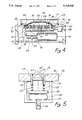
- FIG. 5 is a side elevational view in partial section of one of the retractable rollers utilized on the work station of the invention.
- Illustrated in the flow diagram of FIG. 1 is the movement of a tool as it is progressed along the composite structure mechanized lay up and assembly line of the invention.
- a tool from a tool storage or preheat station 10 is delivered to a tool delivery station 12. From the tool delivery station 12 the tool is then moved to a tool work station 14. While at the tool work station 14 the various plies of a composite part are assembled on the tool and they are debulked. After assembly and debulking is completed the tool having the composite part plies located thereon is then moved to a dispatch station 16. From the dispatch station the composite part bearing tool is then moved to a part transfer and/or cure station 18. I f a composite structure is to be cured directly in the tool on which it was laid up, curing would be effected at station 18. If the part is to transferred to a further curing tool, this also would occur at the station 18. In any event, after transfer and/or cure and removal of the composite part, the tool is then returned to the tool storage and/or preheat station 10.
- FIG. 2 Movement of the tool between the tool delivery station 12, the work station 14 and the dispatch station 16 is shown in a diagrammatic way in FIG. 2.
- the tool dispatch station includes a plurality of rollers 22, as hereinafter described in greater detail, that support the tool 20 at the tool delivery station 12.
- the bottom of the tool 20 is located and supported in plane, a moving plane, depicted by the phantom line 24.
- the work station 14 Adjacent to the tool delivery station 12 is the work station 14.
- the work station 14 includes a plurality of rollers collectively identified by the number 26.
- the rollers 26 differ from the rollers 22, however, in that the rollers 26 can move from the position shown in solid line identified by the numeral 26a to the position shown in phantom line identified by the numeral 26b.
- the apex of these rollers also locate the bottom 28 of the tool 20 in the moving plane 24.
- the rollers 26 move to a retracted position shown by the numeral 26b, the bottom 28 of the tool 20 is moved downward from the moving plane 24 and rests upon a working surface 30 that is part of the work station 14.
- the numeral 20b is utilized to identify the phantom line representation of the tool 20 when it rests on the work surface 28.
- the tool When the tool is in the phantom line position, as shown by the numeral 20b, it is firmly seated on the work surface 30 allowing an operator or technician to assemble an appropriate lay up of composite material plies on the tool.
- the rollers 26 are once again elevated from their recessed position 26b to their elevated position 26a. This raises the tool to an elevated position as depicted by the solid line tool 20a on the work station 14. This once again positions the bottom 28 of the tool in the moving plane 24 allowing the tool 20 to then be rolled across the moving plane to rollers collectively identified by the numeral 32 that are located at the dispatch station 16. Since the apex of the rollers 32 are also located in the moving plane 24, the tool 20 is easily moved from the work station 14 to the dispatch station 16. Tool movement between the tool deliver station 12, the work station 14 and the dispatch station 16 is easily effected by simply hand moving the tool by an operator or technician.
- laying up prepreg plies as for instance a bismaleimide ply, it is generally preferred to drape such plies on a tool that has been preheated to 130° F. ⁇ 10°.
- generally tool preheating can be done, as for instance at a tool storage and preheating station depicted by numeral 10 in FIG. 1.
- the heated state of the tool is maintained by heating the work surface 30 allowing heat to be conducted from the work surface 30 to the tool.
- the work surface 30 is therefore heated in order to maintain the tool at a heated temperature during lay up of the composite plies thereon.
- a typical tool as for instance a 60" by 24" by 4" thick aluminum tool, might weigh upwards of 300 to 500 lbs. Maintaining this heated tool at an elevated temperature can be effected by maintaining the working surface 30 also at an elevated temperature allowing for conduction of heat to the tool. Further, such a tool is easily moved through the moving plane 24 by simple hand movement of an operator because of the ease of movement of the tools on the rollers 22, 26 and 32, respectively, between the tool delivery station 12, the work station 14 and the dispatch station 16.
- FIG. 3 shows the details of the tool delivery station, the work station and the dispatch station of the invention. Again for ease of understanding of the various figures of the drawings, the numerals 12, 14 and 16 also will be utilized to identify the delivery station, work station and dispatch station in FIG. 3.
- the delivery table 34 can be selected as a ball transfer table available from Matthews Conveyor Products. It includes a plurality of caged ball rollers 36 located in a matrix on the table surface 38. Legs 40 (only one of which is shown in the figures) of table 34 are adjustable allowing for alignment of the height of the table surface 38 and the caged ball rollers 36 thereon. Front and back guard rails 42 and 44 are positioned in a parallel arrangement along the sides of the table 34. This allows for entry of a tool at end 46 onto the table 34. Other arrangements could be utilized wherein one or the other of the guard rails 42 or 44 are removed allowing for movement of a tool onto the delivery table 34 from a position other than from the end 46. Shown located on the delivery table 34 is a tool 48.
- the work table 50 Shown located adjacent the delivery table 34 at work station 14 is a work table 50.
- the work table 50 is shown in further detail in FIG. 4.
- the work table 50 includes a platen 52 that is supported by legs, collectively identified by the numeral 54.
- the top of the platen 52 forms a work surface 56.
- Presently preferred for the platen 52 is hard anodized aluminum. Such material is both durable and is a good heat conductor.
- a fixed row of caged ball rollers 58 is located on the left hand end of the work surface 56 and an identical fixed row of fixed caged ball rollers 60 is located on the other end.
- the apex of the roller balls in the assemblies 58 and 60 are at the same height as are the caged ball rollers 36 of the delivery table 34.
- caged ball rollers are positioned with respect to the work surface such that they can be moved to a first or elevated position wherein they project above the work surface 56 or they can be depressed to a second or retracted position wherein they are below the plane of the work surface 56.
- These caged ball rollers are generally identified by the numeral 62 in FIGS. 3 and 4 and one of them is shown in greater detail in FIG. 5.
- the work surface 56 includes a plurality of openings, collectively identified by the numeral 64. Each of the caged ball rollers 62 are located in one of these openings. The caged ball rollers 62 move upwardly and downwardly in these openings as discussed in greater detail below in describing FIG. 5.
- a matrix of inscribed vacuum channels 68 connect between the vacuum port 66 for propagating vacuum across the totality of the work surface 56 as hereinafter explained.
- Hinged via hinges 70 to the work table 50 is a diaphragm frame 72. Located around the edge of the diaphragm frame 72 is seal 74. Integral with the seal 74 is a diaphragm 76. When the frame is rotated about the hinges 70, the seal 74 contacts the work surface 56 inboard of the caged ball rollers 58 and 60, but outboard of the caged ball rollers 62. Further, the vacuum port 66 and inscribed vacuum channels 68 are also inboard of the periphery of the seal 74.
- a seal is positioned directly on the surface of a lay up tool.
- seals do not need to be included on tools.
- the seal 74 could be positioned on the work surface 56, it is preferred in this invention to position the seal 74 directly on the diaphragm frame 72 at the edge of the diaphragm 76. This allows for movement of the seal 74 upward and away from the working surface 56 during tool movement onto and off of the working surface 56. Such positioning of the seal 74 removes it out of harms way during tool movement and thus contributes to longer life of the seal 74.
- the diaphragm 76 is formed of a rubber material that is flexible yet of sufficient strength to impart debulking and consolidation pressure onto composite material laid up on a tool, as for instance, on tool 48.
- the diaphragm 76 can be suspended in the diaphragm frame 72 via "bungie" type straps collectively identified by the numeral 78 that suspend the diaphragm 76 in the diaphragm frame 72 but allow for flexure of the diaphragm 76 downwardly onto a tool and composite prepreg plies located on that tool.
- Dispatch station 16 is formed of a dispatch table 80 that can be identical to the delivery table 34. It would include caged ball rollers 82, legs 84, guard rails 86 and 88 and end 90 essentially as described for the delivery table 34.
- a control unit 92 Located on the front of the work table 50 is a control unit 92. Located below the work table 50 is a vacuum reservoir 94. As is seen in FIG. 4 the vacuum reservoir 94 is connected via vacuum line 96 to vacuum valve 98 and from vacuum valve 98 via line 100 to the vacuum ports 66 located in the working surface 56 of the work table 50. A further vacuum line 102 feeds a control valve 104 for creating a vacuum or low pressure environment within the vacuum reservoir 94.
- heating blankets are located on the bottom of the work table 50 and are connected to and controlled by heater controller 108.
- heater controller 108 In illustrating the heating blankets 106, they are shown in a representational nature only in FIG. 4.
- Other heating means could be utilized to heat the platen 52 of the work table 50.
- insulators could be provided in association with heaters 106 to prevent heat loss from the underneath side of the platen 52.
- the heat controller 108 would be switched on and would maintain the platen 52 of the work table 50 at a preset temperature during a work shift to allow for maintaining of tools at a preset desired temperature when they are located on the work surface 56.
- FIG. 5 Shown in FIG. 5 is the platen 52 and one of the caged ball rollers 62.
- the caged ball roller 62 fits within one of the openings 64 that extend through the working surface 56 into the platen 52.
- a bushing 112 positioned in the platen 52 forms the opening 64.
- the caged ball roller 62 is free to slide in the bushing 112 such that the level of its roller ball 114 is raised and lowered.
- an 0-ring 116 is utilized to seal the cage of the caged ball roller 62 to the opening 64 in the bushing 112.
- a seal 118 is utilized to seal the entirety of the chamber 110 to the underside of the table 50.
- the 0-ring 116 need not be used and the tolerances between the caged ball roller 62 and the bushing 112 can be increased.
- the caged ball roller 62 rests upon a lifting plate 120.
- a spring 122 is positioned between the lifting plate 120 and the bushing 112.
- An inflatable bladder 124 is located within the chamber 110 below the lifting plate 120.
- An air line 126 from a controller 128 connects to the bladder 124.
- the caged ball roller 62 is raised in the bushing 112 by inflating the bladder 124. Inflation of the bladder presses against lifting plate 120 which in turn lifts the caged ball roller 62 and positions the roller ball 114 above the plane of the surface 56. This simultaneously compresses the spring 122. When gas pressure in the bladder 124 is released, the tension in the spring 122 as well as force imparted to the roller ball 114 of the caged ball roller 62 by a tool that may be located on the roller ball 114 depresses the caged ball roller 62 downward within the bushing 112 to a position wherein the apex of the roller ball 114 is below the working surface 56.
- the tool 48 of FIG. 3 has been moved into position on the work table 50 and a series of prepreg plies 130 have been laid onto the tool 48 by a technician or operator of the device.
- a breather cloth 132 is next laid over the top of the plies 130.
- the diaphragm frame 72 is brought down over the combination of the tool, the plies 130 laid up thereon and the breather cloth 122.
- the vacuum reservoir 94 has been evacuated through the vacuum line 102 under the control of the valve 104.
- the valve 98 is then opened allowing for exhaustion of all air between the diaphragm 76 and the working surface 56. This removes any air from between the individual plies 130 and consolidates them under the pressure difference between atmospheric pressure and the evacuated pressure between the diaphragm 76 and the working surface 56. Such evacuation pressure is maintained by the seal 74 against the working surface 56.
- the vacuum is released and the diaphragm frame 72 raised.
- the tool having the consolidated plies of the composite part is then raised by inflating the rubber inflatable bladders 124 within the chambers 110 to raise the caged ball rollers 62 to an elevated position. This raises the tool above the surface 56 allowing for rolling of the tool 56 to the dispatch table 80 at the dispatch station 16.
- vacuum can be slowly created in the reservoir 94 and then essentially instantaneously transferred to the vacuum ports 66 for rapid consolidation of the plies on the tool 48. If a vacuum line was directly fed to the vacuum ports 66 consolidation would be slow as a vacuum was slowly created between the diaphragm 76 and the working surface 56.
- Use of the vacuum reservoir 94 speeds up the consolidation process by pre-creating a vacuum in the reservoir 74 and then opening of a vacuum line between the reservoir 94 and the area between the diaphragm 76 and the working surface 56.
- the tool can be preheated prior to location of the tool at the tool delivery station 12.
- the rollers or caged ball rollers 62 at the work station 14 are then raised allowing for rolling of the tool to the work station 14.
- the caged ball rollers 62 are then retracted to firmly position the tool on the working surface of the work station 14.
- Plies are laid up on the tool as required followed by placement of a release film and a glass cloth on the plies.
- the diaphragm is then brought down onto the ply bearing tool and vacuum is applied to the diaphragm to consolidate the plies on the tool.
- the diaphragm frame is raised, the tool is first raised from the working surface at the work station 14. Then the tool having the consolidated plies thereon is moved to the dispatch station 16 for further processing in forming a composite part.
- the frame 72 is not hinged to the work table 50 but is suspended above the work table 50 by an appropriate mechanical or hydraulic system.
- the suspended frame is lowered and raised towards and upwards from the work table by the mechanical or hydraulic system under the control of an operator of the lay up assembly line.
Abstract
Description
Claims (23)
Priority Applications (1)
| Application Number | Priority Date | Filing Date | Title |
|---|---|---|---|
| US07/847,518 US5328540A (en) | 1992-03-06 | 1992-03-06 | Mechanized lay up assembly line for composite structures |
Applications Claiming Priority (1)
| Application Number | Priority Date | Filing Date | Title |
|---|---|---|---|
| US07/847,518 US5328540A (en) | 1992-03-06 | 1992-03-06 | Mechanized lay up assembly line for composite structures |
Publications (1)
| Publication Number | Publication Date |
|---|---|
| US5328540A true US5328540A (en) | 1994-07-12 |
Family
ID=25300828
Family Applications (1)
| Application Number | Title | Priority Date | Filing Date |
|---|---|---|---|
| US07/847,518 Expired - Lifetime US5328540A (en) | 1992-03-06 | 1992-03-06 | Mechanized lay up assembly line for composite structures |
Country Status (1)
| Country | Link |
|---|---|
| US (1) | US5328540A (en) |
Cited By (27)
| Publication number | Priority date | Publication date | Assignee | Title |
|---|---|---|---|---|
| US5648109A (en) * | 1995-05-03 | 1997-07-15 | Massachusetts Institute Of Technology | Apparatus for diaphragm forming |
| US5954898A (en) * | 1994-05-13 | 1999-09-21 | Lockheed Fort Worth Company | Method and system for fabricating parts from composite materials |
| US5993184A (en) * | 1998-02-05 | 1999-11-30 | The Boeing Company | Magnetic fairing bars for bonding tools |
| WO2000044543A1 (en) * | 1999-01-29 | 2000-08-03 | Alliant Techsystems Inc. | Vacuum debulking table for thermoplastic materials |
| US6478926B1 (en) * | 2000-03-31 | 2002-11-12 | Solectria Corporation | Apparatus and method for forming structural preforms |
| US6786318B1 (en) * | 2003-03-06 | 2004-09-07 | Paul G. Pace | Low frictional transfer apparatus |
| WO2004078442A1 (en) * | 2003-03-06 | 2004-09-16 | Vestas Wind Systems A/S | Pre-consolidated pre-form and method of pre-consolidating pre-forms |
| US20060044376A1 (en) * | 2004-08-26 | 2006-03-02 | Baird Richard W | Apparatus and methods for applying images to a surface |
| US20060197250A1 (en) * | 2005-03-07 | 2006-09-07 | Masanori Shimada | Method of manufacturing reinforcing cloth of sheet pad and apparatus therefor |
| US20070002921A1 (en) * | 2001-11-21 | 2007-01-04 | General Atomics | Laser Containing a Distributed Gain Medium |
| WO2008023293A3 (en) * | 2006-06-28 | 2008-05-02 | Alenia Aeronautica Spa | Method, system and equipment for making parts made of composite material, in particular reinforced parts for aircraft fuselages |
| WO2008135913A1 (en) * | 2007-05-03 | 2008-11-13 | Alenia Aeronautica S.P.A. | Method of manufacturing a z-section component from composite material |
| US20090257860A1 (en) * | 2006-08-21 | 2009-10-15 | Gerhard Schafer | Apparatus and method for unloading trays having a pallet layer loaded |
| US20100077822A1 (en) * | 2008-10-01 | 2010-04-01 | Formtek, Inc. | Duct blank seam and apparatus for making a duct blank seam |
| US20100140831A1 (en) * | 2008-12-05 | 2010-06-10 | Computerized Cutters, Inc. | Molded object-forming apparatus and method |
| US20110185588A1 (en) * | 2005-12-28 | 2011-08-04 | Au Optronics Corp. | Low-Pressure Process Apparatus |
| US20110272257A1 (en) * | 2008-12-19 | 2011-11-10 | Dmitry Borisovich Nikishichev | Rotation unit |
| US8365395B2 (en) | 2010-08-16 | 2013-02-05 | Reading Truck Body, Llc | Tables for assembling composite panels |
| US20130170934A1 (en) * | 2010-09-08 | 2013-07-04 | Bae Systems Plc | System integration |
| US8826509B2 (en) | 2011-10-21 | 2014-09-09 | Spirit Aerosystems, Inc. | Automated multi-stage machine for forming composite details |
| US20150158211A1 (en) * | 2011-11-22 | 2015-06-11 | Premium Aerotec Gmbh | Forming a Profiled Prepreg Component |
| US10213969B2 (en) * | 2016-02-29 | 2019-02-26 | The Boeing Company | Integrated smart susceptor heater blanket and vacuum bag deployment system for large composite skin laminate debulk |
| JP2019107882A (en) * | 2017-12-18 | 2019-07-04 | ザ・ボーイング・カンパニーThe Boeing Company | Lay-up tools that facilitate transfer of laminates to cure tools |
| US10821685B2 (en) | 2018-07-23 | 2020-11-03 | The Boeing Company | Semi-rigid frame for large vacuum bag deployment in composite manufacturing |
| WO2021055224A1 (en) * | 2019-09-19 | 2021-03-25 | Spirit Aerosystems, Inc. | Continuous manufacturing process for composite parts |
| US11155049B2 (en) | 2016-02-23 | 2021-10-26 | Subaru Corporation | Composite material shaping device and composite material shaping method |
| US20220184902A1 (en) * | 2018-12-21 | 2022-06-16 | The Boeing Company | Ply transporting and compacting apparatus and method therefor |
Citations (14)
| Publication number | Priority date | Publication date | Assignee | Title |
|---|---|---|---|---|
| US4036345A (en) * | 1974-10-11 | 1977-07-19 | Hydaroll Limited | Conveyors |
| US4133711A (en) * | 1977-07-11 | 1979-01-09 | Grumman Aerospace Corporation | Automated integrated composite lamination system |
| US4347794A (en) * | 1979-07-19 | 1982-09-07 | Nordstroem Claes | Pallet for use as a load-carrying support |
| US4627526A (en) * | 1985-07-15 | 1986-12-09 | Camillo Masciarelli | Conveyor system with rollers and plungers |
| US4700474A (en) * | 1986-11-26 | 1987-10-20 | Multitek Corporation | Apparatus and method for temporarily sealing holes in printed circuit boards |
| US4706793A (en) * | 1985-07-15 | 1987-11-17 | Camillo Masciarelli | Conveyor system with rollers and plungers |
| US4819554A (en) * | 1987-08-28 | 1989-04-11 | Deere & Company | Transfer and quick change system |
| US4869770A (en) * | 1987-12-03 | 1989-09-26 | The Boeing Company | Method and apparatus for laminating composite materials |
| US4886442A (en) * | 1988-05-26 | 1989-12-12 | The Boeing Company | Vacuum bag tooling apparatus with inflatable seal |
| US4900379A (en) * | 1988-05-20 | 1990-02-13 | The Boeing Company | Method for producing composite materials |
| US4944824A (en) * | 1988-09-23 | 1990-07-31 | E. I. Du Pont De Nemours And Company | Process for preparation of tooling of carbon fiber reinforced polyimide for composites manufacture |
| US4963215A (en) * | 1987-12-07 | 1990-10-16 | The Boeing Company | Method for debulking precured thermoplastic composite laminae |
| US5008520A (en) * | 1988-11-10 | 1991-04-16 | John Georgiou | Method and apparatus for reading a bar code on a moving sheet |
| US5116216A (en) * | 1991-02-28 | 1992-05-26 | The United States Of America As Represented By The Secretary Of The Navy | Apparatus for preparing thermoplastic composites |
-
1992
- 1992-03-06 US US07/847,518 patent/US5328540A/en not_active Expired - Lifetime
Patent Citations (14)
| Publication number | Priority date | Publication date | Assignee | Title |
|---|---|---|---|---|
| US4036345A (en) * | 1974-10-11 | 1977-07-19 | Hydaroll Limited | Conveyors |
| US4133711A (en) * | 1977-07-11 | 1979-01-09 | Grumman Aerospace Corporation | Automated integrated composite lamination system |
| US4347794A (en) * | 1979-07-19 | 1982-09-07 | Nordstroem Claes | Pallet for use as a load-carrying support |
| US4627526A (en) * | 1985-07-15 | 1986-12-09 | Camillo Masciarelli | Conveyor system with rollers and plungers |
| US4706793A (en) * | 1985-07-15 | 1987-11-17 | Camillo Masciarelli | Conveyor system with rollers and plungers |
| US4700474A (en) * | 1986-11-26 | 1987-10-20 | Multitek Corporation | Apparatus and method for temporarily sealing holes in printed circuit boards |
| US4819554A (en) * | 1987-08-28 | 1989-04-11 | Deere & Company | Transfer and quick change system |
| US4869770A (en) * | 1987-12-03 | 1989-09-26 | The Boeing Company | Method and apparatus for laminating composite materials |
| US4963215A (en) * | 1987-12-07 | 1990-10-16 | The Boeing Company | Method for debulking precured thermoplastic composite laminae |
| US4900379A (en) * | 1988-05-20 | 1990-02-13 | The Boeing Company | Method for producing composite materials |
| US4886442A (en) * | 1988-05-26 | 1989-12-12 | The Boeing Company | Vacuum bag tooling apparatus with inflatable seal |
| US4944824A (en) * | 1988-09-23 | 1990-07-31 | E. I. Du Pont De Nemours And Company | Process for preparation of tooling of carbon fiber reinforced polyimide for composites manufacture |
| US5008520A (en) * | 1988-11-10 | 1991-04-16 | John Georgiou | Method and apparatus for reading a bar code on a moving sheet |
| US5116216A (en) * | 1991-02-28 | 1992-05-26 | The United States Of America As Represented By The Secretary Of The Navy | Apparatus for preparing thermoplastic composites |
Cited By (50)
| Publication number | Priority date | Publication date | Assignee | Title |
|---|---|---|---|---|
| US5954898A (en) * | 1994-05-13 | 1999-09-21 | Lockheed Fort Worth Company | Method and system for fabricating parts from composite materials |
| US5648109A (en) * | 1995-05-03 | 1997-07-15 | Massachusetts Institute Of Technology | Apparatus for diaphragm forming |
| US5993184A (en) * | 1998-02-05 | 1999-11-30 | The Boeing Company | Magnetic fairing bars for bonding tools |
| WO2000044543A1 (en) * | 1999-01-29 | 2000-08-03 | Alliant Techsystems Inc. | Vacuum debulking table for thermoplastic materials |
| US6312247B1 (en) | 1999-01-29 | 2001-11-06 | Alliant Techsystems Inc. | Vacuum debulking table for thermoplastic materials |
| US6478926B1 (en) * | 2000-03-31 | 2002-11-12 | Solectria Corporation | Apparatus and method for forming structural preforms |
| US20070002921A1 (en) * | 2001-11-21 | 2007-01-04 | General Atomics | Laser Containing a Distributed Gain Medium |
| US6786318B1 (en) * | 2003-03-06 | 2004-09-07 | Paul G. Pace | Low frictional transfer apparatus |
| WO2004078442A1 (en) * | 2003-03-06 | 2004-09-16 | Vestas Wind Systems A/S | Pre-consolidated pre-form and method of pre-consolidating pre-forms |
| US20060044376A1 (en) * | 2004-08-26 | 2006-03-02 | Baird Richard W | Apparatus and methods for applying images to a surface |
| US7350890B2 (en) | 2004-08-26 | 2008-04-01 | The Boeing Company | Apparatus and methods for applying images to a surface |
| US20080152807A1 (en) * | 2004-08-26 | 2008-06-26 | The Boeing Company | Applying images to a surface |
| US20060197250A1 (en) * | 2005-03-07 | 2006-09-07 | Masanori Shimada | Method of manufacturing reinforcing cloth of sheet pad and apparatus therefor |
| US8926309B2 (en) * | 2005-03-07 | 2015-01-06 | Toyota Tsusho Corporation | Method of manufacturing reinforcing cloth of a seat pad and apparatus therefor |
| US7758802B2 (en) | 2005-03-07 | 2010-07-20 | Toyota Tsusho Corporation | Method of manufacturing reinforcing cloth of sheet pad and apparatus therefor |
| US20090191298A1 (en) * | 2005-03-07 | 2009-07-30 | Toyota Tsusho Corporation | Method of manufacturing reinforcing cloth of sheet pad and apparatus therefor |
| US20110185588A1 (en) * | 2005-12-28 | 2011-08-04 | Au Optronics Corp. | Low-Pressure Process Apparatus |
| US8458872B2 (en) * | 2005-12-28 | 2013-06-11 | Au Optronics Corp. | Low-pressure process apparatus |
| US8950046B2 (en) * | 2005-12-28 | 2015-02-10 | Au Optronics Corp. | Low-pressure process apparatus |
| US20130239383A1 (en) * | 2005-12-28 | 2013-09-19 | Au Optronics Corp. | Low-Pressure Process Apparatus |
| WO2008023293A3 (en) * | 2006-06-28 | 2008-05-02 | Alenia Aeronautica Spa | Method, system and equipment for making parts made of composite material, in particular reinforced parts for aircraft fuselages |
| US20090250165A1 (en) * | 2006-06-28 | 2009-10-08 | Alenia Aeronautica S.P.A. | Method, system and equipment for making parts made of composite material, in particular reinforced parts for aircraft fuselages |
| US7967596B2 (en) | 2006-06-28 | 2011-06-28 | Alenia Aeronautica S.P.A. | Method, system and equipment for making parts made of composite material, in particular reinforced parts for aircraft fuselages |
| US20090257860A1 (en) * | 2006-08-21 | 2009-10-15 | Gerhard Schafer | Apparatus and method for unloading trays having a pallet layer loaded |
| US7735625B2 (en) * | 2006-08-21 | 2010-06-15 | SSI Schäfer Noell GmbH Lager- und Systemtechnik | Apparatus and method for unloading trays having a pallet layer loaded |
| US8118961B2 (en) | 2007-05-03 | 2012-02-21 | Alenia Aeronautica S.P.A. | Method of manufacturing a Z-section component from composite material |
| WO2008135913A1 (en) * | 2007-05-03 | 2008-11-13 | Alenia Aeronautica S.P.A. | Method of manufacturing a z-section component from composite material |
| US20100126658A1 (en) * | 2007-05-03 | 2010-05-27 | Alenia Aeronautica S.P.A. | Method of manufacturing a z-section component from composite material |
| US9810447B2 (en) | 2008-10-01 | 2017-11-07 | Mestek Machinery, Inc. | Duct blank seam and apparatus for making a duct blank seam |
| US8561448B2 (en) * | 2008-10-01 | 2013-10-22 | Mestek Machinery, Inc. | Duct blank seam and apparatus for making a duct blank seam |
| US20100077822A1 (en) * | 2008-10-01 | 2010-04-01 | Formtek, Inc. | Duct blank seam and apparatus for making a duct blank seam |
| US8950229B2 (en) | 2008-10-01 | 2015-02-10 | Mestek Machinery, Inc. | Duct blank seam and apparatus for making a duct blank seam |
| WO2010065533A1 (en) * | 2008-12-05 | 2010-06-10 | Computerized Cutters, Inc. | Molded object-forming apparatus and method |
| US20100140831A1 (en) * | 2008-12-05 | 2010-06-10 | Computerized Cutters, Inc. | Molded object-forming apparatus and method |
| US20110272257A1 (en) * | 2008-12-19 | 2011-11-10 | Dmitry Borisovich Nikishichev | Rotation unit |
| US8365395B2 (en) | 2010-08-16 | 2013-02-05 | Reading Truck Body, Llc | Tables for assembling composite panels |
| US20130170934A1 (en) * | 2010-09-08 | 2013-07-04 | Bae Systems Plc | System integration |
| US8960401B2 (en) * | 2010-09-08 | 2015-02-24 | Bae Systems Plc | System integration |
| US8826509B2 (en) | 2011-10-21 | 2014-09-09 | Spirit Aerosystems, Inc. | Automated multi-stage machine for forming composite details |
| US20150158211A1 (en) * | 2011-11-22 | 2015-06-11 | Premium Aerotec Gmbh | Forming a Profiled Prepreg Component |
| US10737415B2 (en) * | 2011-11-22 | 2020-08-11 | Premium Aerotec Gmbh | Forming a profiled prepreg component |
| US11155049B2 (en) | 2016-02-23 | 2021-10-26 | Subaru Corporation | Composite material shaping device and composite material shaping method |
| US10213969B2 (en) * | 2016-02-29 | 2019-02-26 | The Boeing Company | Integrated smart susceptor heater blanket and vacuum bag deployment system for large composite skin laminate debulk |
| US11014313B2 (en) | 2016-02-29 | 2021-05-25 | The Boeing Company | Integrated smart susceptor heater blanket and vacuum bag deployment system for large composite skin laminate debulk |
| JP2019107882A (en) * | 2017-12-18 | 2019-07-04 | ザ・ボーイング・カンパニーThe Boeing Company | Lay-up tools that facilitate transfer of laminates to cure tools |
| US10821685B2 (en) | 2018-07-23 | 2020-11-03 | The Boeing Company | Semi-rigid frame for large vacuum bag deployment in composite manufacturing |
| US20220184902A1 (en) * | 2018-12-21 | 2022-06-16 | The Boeing Company | Ply transporting and compacting apparatus and method therefor |
| US11697255B2 (en) * | 2018-12-21 | 2023-07-11 | The Boeing Company | Ply transporting and compacting apparatus and method therefor |
| WO2021055224A1 (en) * | 2019-09-19 | 2021-03-25 | Spirit Aerosystems, Inc. | Continuous manufacturing process for composite parts |
| US11865803B2 (en) | 2019-09-19 | 2024-01-09 | Spirit Aerosystems, Inc. | Continuous manufacturing process for composite parts |
Similar Documents
| Publication | Publication Date | Title |
|---|---|---|
| US5328540A (en) | Mechanized lay up assembly line for composite structures | |
| US5772950A (en) | Method of vacuum forming a composite | |
| US10974464B2 (en) | Method for forming contoured composite laminates | |
| EP1507647B1 (en) | Controlled atmospheric pressure resin infusion process | |
| US6705853B1 (en) | Six station rotary thermoforming machine | |
| US5209804A (en) | Integrated, automted composite material manufacturing system for pre-cure processing of preimpregnated composite materials | |
| EP0228719A2 (en) | Method and apparatus for consolidating composite materials | |
| EP2512786B1 (en) | High temperature composite tool | |
| US5820894A (en) | Method and apparatus for consolidating a workpiece at elevated temperature | |
| US4859267A (en) | Method for consolidating composite materials | |
| EP1147001B1 (en) | Vacuum debulking table for thermoplastic materials | |
| US20080210372A1 (en) | Composite article debulking process | |
| CN105773996B (en) | Forming includes the forming tool and method and building mortion of the semi-finished product of reinforcing fiber | |
| KR101786384B1 (en) | Apparatus and method manufacturing fiber reinforced plastic products | |
| JP7022175B2 (en) | Laminate molding system and laminating molding method and laminating equipment | |
| CN111347752B (en) | Laminate conveying and compacting apparatus and method | |
| EP4241972A1 (en) | Stringer forming apparatus and method | |
| JP2574424B2 (en) | Manufacturing method of pile mat with backing rubber | |
| KR20150127470A (en) | Mould for forming fiber-reinforced composite material easying gas emissions | |
| US11383462B2 (en) | Auto-aligning vacuum press | |
| EP4019234A2 (en) | Forming apparatus, method, and system | |
| KR20240030439A (en) | Apparatus for forming prepreg | |
| JP3228443B2 (en) | Molding equipment for resin molded products | |
| JP2783907B2 (en) | Thermoplastic resin high performance fiber reinforced composite sheet forming equipment | |
| GB2300138A (en) | Seal arrangement in vacuum bagging moulding |
Legal Events
| Date | Code | Title | Description |
|---|---|---|---|
| AS | Assignment |
Owner name: NORTHROP CORPORATION A CORPORATION OF DE, CALIF Free format text: ASSIGNMENT OF ASSIGNORS INTEREST.;ASSIGNORS:CLAYTON, COLIN G.;CHANG, FRANK R.;REEL/FRAME:006055/0346 Effective date: 19920306 |
|
| STCF | Information on status: patent grant |
Free format text: PATENTED CASE |
|
| FEPP | Fee payment procedure |
Free format text: PAYOR NUMBER ASSIGNED (ORIGINAL EVENT CODE: ASPN); ENTITY STATUS OF PATENT OWNER: LARGE ENTITY |
|
| AS | Assignment |
Owner name: SANDIA CORPORATION, NEW MEXICO Free format text: ASSIGNMENT OF ASSIGNORS INTEREST;ASSIGNOR:DRAPER, BRUCE L.;REEL/FRAME:008764/0465 Effective date: 19971006 |
|
| FPAY | Fee payment |
Year of fee payment: 4 |
|
| FPAY | Fee payment |
Year of fee payment: 8 |
|
| REMI | Maintenance fee reminder mailed | ||
| FPAY | Fee payment |
Year of fee payment: 12 |
|
| AS | Assignment |
Owner name: NORTHROP GRUMMAN SYSTEMS CORPORATION, CALIFORNIA Free format text: ASSIGNMENT OF ASSIGNORS INTEREST;ASSIGNOR:NORTHROP GRUMMAN CORPORATION;REEL/FRAME:025597/0505 Effective date: 20110104 |