US5237520A - Foot measurement and footwear sizing system - Google Patents
Foot measurement and footwear sizing system Download PDFInfo
- Publication number
- US5237520A US5237520A US07/891,166 US89116692A US5237520A US 5237520 A US5237520 A US 5237520A US 89116692 A US89116692 A US 89116692A US 5237520 A US5237520 A US 5237520A
- Authority
- US
- United States
- Prior art keywords
- foot
- menu
- reference surface
- portions
- footwear
- Prior art date
- Legal status (The legal status is an assumption and is not a legal conclusion. Google has not performed a legal analysis and makes no representation as to the accuracy of the status listed.)
- Expired - Lifetime
Links
- 238000005259 measurement Methods 0.000 title description 14
- 238000004513 sizing Methods 0.000 title description 9
- 238000000034 method Methods 0.000 claims abstract description 21
- 230000000007 visual effect Effects 0.000 claims abstract description 5
- 230000003287 optical effect Effects 0.000 claims description 10
- 239000003086 colorant Substances 0.000 claims description 9
- 238000013507 mapping Methods 0.000 claims description 3
- 238000012545 processing Methods 0.000 claims description 3
- 210000002683 foot Anatomy 0.000 description 161
- 238000004519 manufacturing process Methods 0.000 description 21
- 238000003860 storage Methods 0.000 description 19
- 238000010586 diagram Methods 0.000 description 14
- 238000004891 communication Methods 0.000 description 7
- 230000008569 process Effects 0.000 description 6
- 238000007619 statistical method Methods 0.000 description 5
- 239000011257 shell material Substances 0.000 description 4
- 235000019642 color hue Nutrition 0.000 description 3
- 230000007246 mechanism Effects 0.000 description 3
- 238000012552 review Methods 0.000 description 3
- 210000003371 toe Anatomy 0.000 description 3
- 238000004458 analytical method Methods 0.000 description 2
- 238000004422 calculation algorithm Methods 0.000 description 2
- 210000001872 metatarsal bone Anatomy 0.000 description 2
- 238000012546 transfer Methods 0.000 description 2
- 230000004913 activation Effects 0.000 description 1
- 239000008280 blood Substances 0.000 description 1
- 210000004369 blood Anatomy 0.000 description 1
- 238000004364 calculation method Methods 0.000 description 1
- 230000008859 change Effects 0.000 description 1
- 230000002860 competitive effect Effects 0.000 description 1
- 238000010276 construction Methods 0.000 description 1
- 238000013500 data storage Methods 0.000 description 1
- 230000001419 dependent effect Effects 0.000 description 1
- 238000013461 design Methods 0.000 description 1
- 238000012938 design process Methods 0.000 description 1
- 230000007613 environmental effect Effects 0.000 description 1
- 210000004744 fore-foot Anatomy 0.000 description 1
- 230000006870 function Effects 0.000 description 1
- 230000004886 head movement Effects 0.000 description 1
- 238000009413 insulation Methods 0.000 description 1
- 238000007726 management method Methods 0.000 description 1
- 239000000463 material Substances 0.000 description 1
- 238000000691 measurement method Methods 0.000 description 1
- 238000012986 modification Methods 0.000 description 1
- 230000004048 modification Effects 0.000 description 1
- 230000002093 peripheral effect Effects 0.000 description 1
- 238000003825 pressing Methods 0.000 description 1
- 230000009467 reduction Effects 0.000 description 1
- 230000003595 spectral effect Effects 0.000 description 1
- 230000003068 static effect Effects 0.000 description 1
Images


Classifications
-
- A—HUMAN NECESSITIES
- A43—FOOTWEAR
- A43D—MACHINES, TOOLS, EQUIPMENT OR METHODS FOR MANUFACTURING OR REPAIRING FOOTWEAR
- A43D1/00—Foot or last measuring devices; Measuring devices for shoe parts
- A43D1/02—Foot-measuring devices
- A43D1/025—Foot-measuring devices comprising optical means, e.g. mirrors, photo-electric cells, for measuring or inspecting feet
-
- A—HUMAN NECESSITIES
- A61—MEDICAL OR VETERINARY SCIENCE; HYGIENE
- A61B—DIAGNOSIS; SURGERY; IDENTIFICATION
- A61B5/00—Measuring for diagnostic purposes; Identification of persons
- A61B5/103—Detecting, measuring or recording devices for testing the shape, pattern, colour, size or movement of the body or parts thereof, for diagnostic purposes
- A61B5/1036—Measuring load distribution, e.g. podologic studies
-
- A—HUMAN NECESSITIES
- A61—MEDICAL OR VETERINARY SCIENCE; HYGIENE
- A61B—DIAGNOSIS; SURGERY; IDENTIFICATION
- A61B5/00—Measuring for diagnostic purposes; Identification of persons
- A61B5/103—Detecting, measuring or recording devices for testing the shape, pattern, colour, size or movement of the body or parts thereof, for diagnostic purposes
- A61B5/107—Measuring physical dimensions, e.g. size of the entire body or parts thereof
- A61B5/1074—Foot measuring devices
Definitions
- This invention relates in general to the footwear manufacturing process including sales from a retail store, footwear design, last production, and finally the manufacturing of footwear. More particularly, it relates to an integrated computerized system for measuring and sizing feet and providing custom fit footwear for customers while maintaining optimized inventory of footwear for retail stores and manufacture of footwear. In addition, through statistical analysis of customer orders, it can be determined which footwear lasts are most likely to be required for producing footwear to fit a particular portion of the general population. This system thereby enables more accurate and efficient production of footwear and lasts for the general public consumption. Further, the present invention utilizes the foot sizing method and last production method disclosed in a co-pending U.S. patent application Ser. No. 416,624, filed Oct. 3, 1989, now issued as U.S. Pat. No. 5,123,169 on Jun. 23, 1992, hereinafter referred to as the TWACTM measurement system.
- the footwear industry has been a highly specialized and competitive environment. Most footwear manufacturers have felt a need to be as efficient as possible while providing high quality footwear for the majority of consumers. In recent years, this desire for efficiency has been increased due to the rise in international trade and competition as well as increased consumer demand. Therefore, footwear manufacturers have found it necessary to adapt to the market conditions by providing as many styles and sizes of shoes as possible to the public to better serve the needs of the consumers.
- computerized automation of the footwear industry has been relatively limited; however, with the advent of more sophisticated computing machines and software to drive the computing machines, it has become possible to integrate the entire process of manufacturing footwear.
- the present invention provides a solution to this need for improved productivity and efficiency by integrating the entire process of selling retail footwear. As will be discussed below, the present invention seeks to integrate the entire footwear sales process including, at least, improved measurement capabilities, matching the foot to particular footwear, and the footwear design process, the footwear manufacturing process.
- a method for measuring bottom facing surfaces of foot which comprises the steps of placing a foot against a reference surface within the scanning field of the scanner, scanning bottom facing surfaces of a foot, and electronically displaying the scan of the foot bottom facing surfaces on a visual display to produce a scanned foot image articulating distances of portions of the foot bottom facing surface from the reference surface.
- the electronically displaying step may further include assigning gray scale values to distances articulated to produce a scan foot image comprising more than two gray scale intensities so that a grey scale image with a stereoscopic appearance is provided.
- the electronically displaying step may include assigning color hues to the distances articulated to produce an image comprising more than two spectral hues so that a color image with a stereoscopic appearance is provided.
- a method for measuring bottom facing surfaces of the foot which includes a step of electronically displaying the scan of the foot bottom facing surfaces on a visual display to produce a scan foot image distinguishing regions of the foot bottom facing surface exerting different pressures against the reference surface and assigning grey scale or color values to the foot pressure regions.
- a system for topographically mapping bottom facing surfaces of a foot is provided.
- FIG. 1 is a block diagram showing a generalized diagram of the present computerized system.
- FIG. 2 is a block diagram showing a preferred embodiment of the present electro-optical foot scanner system.
- FIG. 3 is a block diagram showing a detailed depiction of the elements of the preferred embodiment central computer.
- FIG. 3A is a block diagram showing a detailed depiction of the elements of the preferred embodiment electro-optical foot scanner.
- FIGS. 4A, 4B and 4C show a flowchart diagramming an example of operating a preferred embodiment electro-optical foot scanner unit from a user's point of view.
- FIG. 5 shows a flowchart diagramming an alternative example of operating a preferred embodiment electro-optical scanner unit from a user's point of view.
- FIGS. 6 through 67 are representations of example menu/screen displays presented to a user during operation of the preferred embodiment electro-optical scanner unit in accordance with the flowchart diagrams, shown in FIGS. 4A, 4B, 4C and 5.
- FIG. 1 is a block diagram showing a generalized diagram of the present computerized system.
- the present computerized system encompasses a preferred footwear manufacturing environment from the retail store outlet through the manufacturing process and back to the retail footwear store.
- an electro-optical foot scanner unit 100 would preferably be placed to determine customer footwear size needs.
- Foot scanner unit 100 would derive a three-dimensional topographical image of a particular customer's feet. From the electronically derived topographical image of the feet, a foot size is electronically computed.
- the foot size could be assigned according to any foot sizing method including, for example, the Brannock measuring system, the TWACTM measurement system and others.
- Foot measurement information for the particular customer would be stored in a database for a later transference to a centralized database.
- a substantially instantaneous electronic query can be made by way of a computing device into electronically stored inventory data to determine if such a size is available of the desired footwear to provide to the particular customer.
- the following will describe the procedures for transferring the foot sizing information of a particular customer to the manufacturing facilities so that custom fit footwear can be made and subsequent transference of that finished product back to the retail footwear store is accomplished.
- information is transferred to a central storage facility for a particular retail footwear store 102.
- a centralized database 104 by way of one of several communication methods including a computerized network transfer, serial data communication, parallel data communication, and modem communication or by transferring a storage medium such as a floppy disk, magnetic tape, optical disk, punch tape, punch card, or other storage medium readable by an electronic computing means.
- a query into an existing footwear last database 116 is checked electronically for a last which could be used to manufacture a custom fit piece of footwear for the particular customer.
- information would be stored on all lasts kept for use in manufacturing particular footwear according to size and style.
- lasts preferably would be selected which closely match the particular customer's needs as well as lasts which exactly match the particular customer's needs. If it is determined that a last exists which would be useable for the particular custom footwear, information can be transferred to footwear production facilities 114 so that the chosen last can be used to manufacture custom fit footwear and other footwear products for the customer.
- Custom footwear products could include items such as custom fit insoles, heel cups, metatarsal support, volume adjustment shims, and the like. Custom footwear could include boots, shoes, and other various forms of footwear.
- the foot measurement information for the customer can be transferred to a CAD/CAM machine 110 which electronically receives the scanned feet data and style preference information. From the received data the CAD/CAM machine 110 generates machine control code for producing a last. Once the machine control code is generated, the information may be transferred electronically or otherwise to a last production machine 112 which can produce a unique last for the customer. After producing the unique last for the customer, the last can be transferred to the footwear manufacturing facilities 114 so that custom footwear and footwear products can be manufactured for the customer. In the preferred embodiment, the manufactured footwear and footwear products can then be sent to the retail footwear store 102 for delivery to the customer. The unique last may also be transferred to the retail footwear store for storage at the retail footwear store or delivery to the customer so that the customer can save the last for subsequent manufacturing of custom footwear and footwear products.
- Centralized footwear database 104 also has links to a mechanism which can perform statistical trend analysis 106 for determining such information as may be desired.
- Some of the statistical trend analysis may include particular styles or sizes of styles which are requested frequently by customers as well as which lasts are the best lasts to store for subsequent use in manufacturing products for other customers.
- the statistical analysis mechanism 106 can transfer the information to quality and inventory control mechanisms 108 so that improvements in the styles and sizes of existing lasts used in mass production of footwear can be made if desirable by modifying the information stored in the existing last database 116. Substantial last and footwear inventory reductions are possibly utilizing this improved method of last inventory management.
- FIG. 2 a block diagram showing the preferred embodiment of the present electro-optical foot scanner system 100 is shown.
- a central computing device 120 controls operations of several peripheral devices.
- Display 122 is coupled to central computer 120 so that information which is received by the central computer may be displayed for viewing by a user.
- Display 122 in the preferred embodiment includes an electronic video display capable of reproducing images consisting of a plurality of hues and shades of color.
- central computer 120 is coupled to inventory data 124 which can be stored in storage device 130 or in other storage devices proximate foot scanner unit 100.
- Inventory data 124 includes information concerning number of footwear available at retail footwear store 102 in particular styles and sizes. Further inventory data 124 may include information which indicates all footwear styles and sizes available from a footwear manufacturer 114 at a particular retail footwear store 102 on request, or other information.
- Input device 126 provides means for obtaining information from a user and supplying such information to central computer 120.
- Input device 126 may include many types of electronic input devices including a keyboard, mouse, track ball, light pen, electronic tablet, and touch screen, voice recognition unit, or other devices. It will be appreciated by those skilled in the art that improved input devices may be substituted for use in the preferred embodiment as they are developed.
- foot scanner unit 100 is optimized for use with a combination of keyboard and touch screen input devices. These input devices are used to select menu choice options presented on display 122 as well as input and retrieve information used by central computer 120.
- a storage device 130 is coupled to central computer 120 for local storage of information received by central computer 120.
- Storage device 130 may be configured in several forms including combination of tape drives, hard disk drives, floppy disk drives, optical disk drives, static ram or other electronic storage devices. It will be appreciated by those skilled in the art that the particular storage device used will be highly dependent upon the performance characteristics desired for use in the particular environment in which the foot scanner unit is to be utilized. In the preferred embodiment, a hard disk drive is utilized for local storage of information.
- a scanner unit 134 is coupled to central computer 120.
- the scanner unit 134 provides a three-dimensional, topographical electronic image of a foot which has been scanned.
- the scanner unit 134 provides precision contour mapping of bottom surfaces and substantially bottom facing surfaces of a scanned foot.
- Particular topographical information concerning a particular foot may be derived by determining the intensity of lightness and darkness of portions of the scanned foot image with respect to other portions of the scanned foot image. In particular, image portions which are generally lighter in color or intensity are designated as being closer to the scanner unit than portions of the foot which are darker in color or intensity.
- parts of the foot which actually touch the surface of the electro-optical scanner 134 are all the same distance from the surface of the scanner; however, the color of the scanned foot still varies.
- the color of the surface of the foot pressed against the surface of the scanner 134 may vary according to the amount of pressure applied to the surface of the scanner unit in direct correlation to the amount of blood flowing through the foot surface at that particular point.
- foot surfaces under extreme pressure will be lighter in color hue than foot surfaces under less pressure which will be generally pinkish or skin tone in color.
- the foot scanner 134 may be adjusted to accommodate a foot with light skin tone, dark skin tone, a white sock, or even a dark sock by varying the intensity of the light source used in the electro-optical scanning process which is directed at the foot being scanned. It will be appreciated by those skilled in the art that improved scanner units may be substituted for use in the preferred embodiment foot sizing system without departing from the teachings of the present invention.
- topographical information on a foot may be utilized such as laser-optic scanners, CAT scanners, pressure plate scanners, resistive force plates, nuclear magnetic scanners, acoustic-based scanners, variable height pin and electromechanical array based scanners, or other three-dimensional measurement devices in place of the preferred embodiment electro-optical scanner.
- a printer 128 may also be coupled to central computer 120 so that hard copy of information which has been displayed on display 122 may be provided to a user or customer.
- the information stored and manipulated by central computer 120 may also be provided to statistical analysis tools 132 for use in computing optimum retail store inventory of footwear, ordering more inventory of footwear, determining the most popular styles of footwear, or other various statistical analysis which may utilize information already stored through central computer 120.
- Central computer 120 preferably includes several optimized elements for manipulating and interfacing with externally coupled devices.
- Central computer 120 is generally operated through a central processing unit (CPU) 142 which is logically coupled to a central bus 140.
- Bus 140 passes data between all of the elements of central computer 120.
- CPU 142 communicates with a scanner basic input/output system (BIOS) 144 which is in turn coupled through bus 140 to a small computer system interface (SCSI) 150 operatively interconnected to the scanner.
- BIOS 144 provides instructions to the scanner during the scanning process and helps control the flow of information to and from the scanner.
- CPU 142 further communicates through bus 140 to video controller 146 which is operatively interconnected to the display or monitor.
- Video controller 146 generates display screens compatible with the monitor from information provided by CPU 142. Such information may include an electronically enhanced scanned image of a customer's foot, footwear catalog information, pricing, and retail footwear store inventory.
- the electronically enhanced scanned image preferably is displayed in a plurality of colors or shades of a single color.
- those portions of the scanned foot image which have been determined to be closest to the scanner 134 surface by central computer 120 are assigned the colors of lightest hue or shades of a single color of highest intensity.
- the portions of the foot surface deemed to be furthest away from the scanner 134 surface by central computer 120 are assigned colors of darker hues or shades of a single color which are darker in light intensity than those assigned to portions of the foot which were deemed closer to the scanner 134 surface by central computer 120.
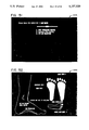
- a scanned foot image such as the one shown in FIGS. 8 and 9, has a stereoscopic appearance due to the assignment of shades of gray which are lighter or darker based on distance of the foot from the scanner 134 surface.
- lighter shades of gray have been assigned to the bottoms of the toes and heel which are under higher pressure due to the weight of the owner of the foot than the surrounding areas which are also touching the scanner 134 surface.
- the portions of the scanned foot which are not touching the surface of the scanner are also assigned lighter shades of gray if those portions are nearer the scanner 134 surface than the surrounding areas which are not touching the scanner 134 surface.
- CPU 142 is further coupled through bus 140 to serial input/output interface 148 which provides a communication port through which input devices, preferably including a keyboard and touch screen may provide information to CPU 142.
- serial input/output (I/O) device 148 is operatively interconnected to remotely located inventory data 124 via a local area network, modem or other form of serial communication.
- the remotely located inventory data 124 may be stored within centralized database 104.
- CPU 142 is operatively interconnected through bus 140 to specialized micro-chip controllers which improve the performance of central computer 120 by reducing the demands on CPU 142.
- These specialized chips include a math co-microprocessor 156 and direct memory access (DMA) controller 154.
- Math co-microprocessor 156 alleviates much of the computational demand placed on CPU 142 for the graphic intensive operations of central computer 120 thereby allowing CPU 142 to work on other tasks more efficiently.
- DMA controller 154 also alleviates part of the data manipulation load placed on CPU 142 by controlling data access to relatively slow data storage devices such as the storage devices connected to hard disk controller 158 and data being received from serial I/O device 148 as well as SCSI controller 150.
- a parallel input/output device controller 152 is included in central computer 120 for controlling communications through bus 140 to CPU 142 which are from a printer or other external device using a parallel input/output interface.
- electro-optical foot scanner 134 includes an optical scan head 160 which moves along a fixed track 162 during the scan process.
- Scanner 134 also includes a control unit 164 which adjusts the light intensity of the optical scan head 160, the speed at which the optical scan head 160 moves within track 162 during scanning operations, and the flow of data to and from central computer 120 which is coupled to scanner 134 through logical connection 166.
- Scanner 134 also includes a planar reference surface 170. Other shaped reference surfaces may be substituted for planar reference surface 120 without departing from the teachings of the present invention. For instance, a reference surface generally formed such that it conforms to the bottom surface of a foot may be utilized.
- control unit 164 consists of a Tokyo Electric Company, Limited optical scanner engine which provides a reference surface which is large enough to accommodate foot sizes up to twenty according to the Brannock measuring system or more specifically 520 ⁇ 220 pixel resolution where each pixel is 5 mm square.
- the Tokyo Electric Company, Limited engine allows adjustment of the light source intensity used in conjunction with the optical scan head including eight levels of brightness and six levels of contrast.
- the Tokyo Electric Company, Limited engine provides relatively quick optical scan head movement and therefore relatively quick scanning of the bottom facing surface of foot 168.
- the central computer 120 includes computational elements for deriving a level heel to foot length, foot width, arch-line, and foot curvature measurement from the data received from foot image data received from scanner 134. It will be appreciated by those skilled in the art that other scanners may be substituted for the particular scanner specified above which meet or exceed the particular specifications of the Tokyo Electric Company, Limited scanner engine.
- FIGS. 4A, 4B, and 4C these figures encompass a flowchart of an example showing the use of the preferred electro-optical foot scanner unit, shown in FIG. 2.
- the flowchart diagram is an example of using electro-optical foot scanner unit from a user's point of view by depicting graphical and textual information which may be shown to a user. This information preferably is shown to a user on a video display screen for review and/or for providing continued navigation through a series of display screens.
- a user is given a choice to select from a plurality of options including an option to go to a scan foot menu/screen display 202.
- an input device 126 hereinafter referred to as selecting
- a scan foot menu/screen display 202 such as the one shown in FIG. 7 is presented on the display 122.
- a user may choose to select scanning of foot which is bare, which has a light sock, or which has a dark sock.
- a foot is scanned by scanner 134.
- the information is processed by central computer 120 and the scanned foot image 204 is displayed on display 122.
- display screen 204 (not shown) displays the portion of the particular foot which has already been scanned.
- a user will focus their attention on the scanned image rather than the length of time that it actually takes to scan the foot, thereby causing the scanning of the foot to be relatively quick from a user's point of view.
- open menu/screen display 200 is presented to the user once again. After scanning both the left and right foot in a substantially similar manner as described above, the user may choose to calculate information about the scanned feet.
- display scanned foot information menu/screen display 206 upon selecting to calculate the feet information, is presented on display 122.
- Menu/screen display 206 displays information about each of the scanned feet including Brannock foot sizes and TWACTM foot sizes.
- Menu/screen display 206 further displays an image of the scanned foot which contains overlaid highlight lines including a heel to toe length highlight, center line highlight, heel width highlight, ball width highlight and T point circle highlight.
- the TWACTM measurement system includes calculating a length measurement from a foot centerline from the heel to toe, a width line between medial and lateral portions of the foot or between flexion points, an arch-line type, and the angle of curvature of the medial edge and the lateral edge of the foot as determined from a heel point at the base of the heel. Also included in the TWACTM foot sizing measurement system are calculations of heel width and foot volume.
- enter volume information menu/screen display 208 is displayed on the screen display 122.
- the volume information may be automatically measured by the scanner unit and entered into the center computer.
- a user is prompted to enter a volume number measured by a strap wrapped from the heel to the instep of the foot.
- menu/screen display 210 is presented on display 122.
- a user may select from a plurality of options including correcting volume information or branching to three other software program modules including complete data module, quick fit module, style fit module. If a user chooses to correct volume information, menu/screen display 208 is presented on display 122 for the particular foot selected.
- select name option menu/screen display 212 Upon selecting the complete data module, select name option menu/screen display 212, shown in FIG. 11, is presented on display 122.
- menu/screen display 214 Upon selecting to attach the foot scan image information to a file, menu/screen display 214, shown in FIG. 12, is presented on display 122.
- a user selects one of five available current customer files to save the customer information under.
- menu/screen display 216 Upon selecting a particular current customer file to save the scanned foot image information under which automatically assigns new input to a storage file in storage device 130, menu/screen display 216, shown in FIG. 13, is presented on screen display 122.
- the display screen keyboard prompts the user to input a customer name, address, phone number and age by selecting the characters on menu/screen display 216.
- menu/screen display 220 is presented on display 122.
- menu/screen display 222 is presented on screen display 122.
- menu/screen display 224 is presented on display 122.
- menu/screen display 226, shown in FIG. 18, is presented on display 122.
- menu/screen display 228, shown in FIG. 19 is presented on display 122.
- menu/screen display 230 is presented on display 122.
- the user shall review the scanned foot image and select the amount of pronation of the foot or select unable to answer this question and central computer 120 shall determine the amount of pronation.
- menu/screen display 232 shown in FIG. 21, is presented on display 122.
- the user is prompted to check the customer information for errors and correct such information where needed.
- the information can be corrected by selecting the incorrect information, returning to that particular menu/screen display, correcting the information and returning to menu/screen display 232.
- menu/screen display 212 shown in FIG. 11, is once again presented on screen display 122.
- the user may now choose to select a particular piece of footwear.
- Screen display 234 indicates that central computer 120 is loading footwear information into memory.
- menu/screen display 236, shown in FIG. 23, automatically is displayed on display 122.
- a user selects one of the current customer files for which to find footwear.
- the user may choose to exit this portion of the program and return to menu/screen display 200, shown in FIG. 6.
- the user may choose to retrieve customer information from a file stored in storage device 130 to use in conjunction with selecting particular footwear.
- a user may choose to indicate that a quick fit of footwear would like to be accomplished.
- menu/screen display 240 Upon choosing to select particular footwear, menu/screen display 240, shown in FIG. 25, is presented on display 122 wherein the user is prompted to either select another person for which to find footwear and automatically returns to menu/screen display 236 or selects to continue operation by running the footwear selection module.
- menu/screen display 242 shown in FIG. 26, is presented on display 122.
- central computer 120 determines that a foot of unusual dimensions has been scanned, the user is presented with menu/screen display 241, shown in FIG. 26A, which asks the user to branch directly to the fitting specifications menu/screen display 246, shown in FIG. 30, before recommending footwear for the customer.
- a priority assignment and sorting algorithm is used to select footwear models and sizes that match the use categories previously selected by the user.
- the first seven footwear styles selected by the algorithm are presented on menu/screen display 243, shown in FIG. 27.
- the items automatically checked for availability in inventory and those which are available are preferably shown in darker (more definite) characters. Similarly, those which are not available in current inventory are preferably displayed in a lighter (less definite) characters.
- menu/screen display 244, shown in FIG. 28, is presented on display 122.
- the user is asked to select whether or not adjustment to the fitting specifications is necessary. If such adjustments to the fitting specifications are indicated by the user, menu/screen display 246, shown in FIG. 30, is presented on display 122.
- indicators 249 are shown next to particular information categories which central computer 120 has calculated most likely to require adjustment to allow more precise fitting of a customer's foot. Thus, a customer can be prompted to adjust the most likely categories to need adjustment based on the information that central computer 120 has previously been given.
- a particular category such as heel width as depicted in menu/screen display 247, shown in FIG. 31, the user is prompted to adjust the fitting specifications. After adjusting the fitting specifications, the user selects to continue program operation and menu/screen display 242, shown in FIG. 26, is presented on display 122.
- menu/screen display 245, shown in FIG. 29, is presented on display 122.
- the user may choose to print a hard copy of the suggested footwear on printer 128.
- the user may select three different printout formats including complete hard copy of suggested footwear information for footwear in current inventory, only the names of particular suggested footwear, or all suggested footwear without an inventory check for current availability.
- the user preferably selects to continue program operation and branch point menu/screen display 248, shown in FIG. 32 is presented on display 122. From this menu/screen display, a user may choose to select a shoe for the next person, make changes to current data, return to the fit screen control program, branch to the footwear product catalog, branch to the last overlay viewing program module, or branch to the fit aid recommendations program module.
- central computer 120 Upon indicating a desire to select a shoe for the next person, central computer 120 branches to menu/screen display 236, shown in FIG. 23, and continues normal operation from that point. Upon indicating to make data changes, central computer 120 branches to menu/screen display 246, shown in FIG. 28, and continues normal operation from that point. Upon indicating a desire to branch to fit/scan control, central computer 120 branches to menu/screen display 200, shown in FIG. 6, and continues normal operation from that point. Alternatively, upon indicating a desire to review the footwear product catalog, menu/screen display 260, as shown in FIG. 38, is presented on display 122 and central computer 120 continues normal operation from that point in the flow diagram shown on FIG. 4C.
- menu/screen display 272 shown in FIG. 44
- normal operation of central computer 120 is continued as shown in the flow diagram shown in FIG. 4C.
- menu/screen display 282 shown in FIG. 49
- central computer 120 continues normal operation from that point as shown in program flow diagram FIG. 4A.
- a user may choose to enter the quick fit module.
- the quick fit program module is designed to work with only scan data and without customer information.
- menu/screen display 234, shown in FIG. 22 is presented on display 122.
- Menu/screen display 234 indicates that central computer 120 is loading footwear information into memory.
- menu/screen display 238, shown in FIG. 24, is presented on display 122.
- screen display 240 is presented on display 122 and central computer 120 continues on in the program flow as indicated in FIG. 4B and as previously detailed in the discussion of the complete data module.
- menu/screen display 210 shown in FIG. 10
- the user may select to enter the style fit module.
- menu/screen display 250 shown in FIG. 33
- the user is prompted to select a particular style of footwear which they would like to be fitted for. For instance, a user may choose to pick a particular shoe from the selections shown in menu option entitled page 1.
- menu/screen display 252 shown in FIG. 34
- a user is prompted to select a particular style of footwear for which to be fitted.
- menu/screen display 254 shown in FIG. 39
- Menu/screen display 254 provides particular information about the chosen style of footwear including sizes and widths available according to the Brannock measurement system and particular features of this footwear, including liner, insole, insulation, dressing, construction and sole. A user may choose to return immediately to one of the particular style pages such as page 1, shown in menu/screen display 252, return to the main style menu/screen display 250, or to fit this style.
- menu/screen display 256 Upon choosing to fit this particular style, menu/screen display 256, shown in FIG. 36, is presented to the user. After entering the particular sex of the customer, last overlay menu/screen display 258, shown in FIG. 37, is presented on display 122. The last overlay menu/screen display 258 shows how the particular chosen style of footwear will fit on the currently selected scanned foot information. The user may move the style last overlay outline 259 with respect to the scanned foot image 257 by selecting movement indicator menu options 255. After viewing the particular style last overlay 259 on the scanned foot, the user selects to return to menu/screen display 250. Subsequently, from menu/screen display 250, the user may choose to return to menu/screen display 200, shown in FIG. 6, or fit another footwear style to the particular foot currently selected.
- menu/screen display 210 shown in FIG. 10
- the user may select to enter the catalog module.
- menu/screen display 260 shown in FIG. 38
- display 122 is presented on display 122.
- the styles available may be presented on display 122 in textual menus as shown in menu/screen display 260.
- the styles may be shown in graphical depictions of particular styles of shoes available such as hiking boots, running shoes, service shoes, work boots, etc. For example, a user may choose to view shoes from page 3, as shown in menu/screen 262, shown in FIG. 39.
- the list of particular footwear may be shown in a textual or graphical manner as discussed above. Such that miniature graphical representatives of footwear may be shown in place of the textual listing of the name of the footwear.
- a user may choose to view a particular piece of footwear.
- menu/screen display 264 shown in FIG. 40, is presented on display 122.
- Information about the particular footwear selected is presented to the user including sizes and widths available according to the Brannock sizing system and particular features of this particular footwear.
- a user may choose to return to the same or different pages of the catalog or to the main menu catalog screen 260, shown in FIG. 38. Alternatively, a user may choose to more closely view the particular footwear selected.
- menu/screen display 264 includes miniature pictures of the side 263, top 263' and bottom 263" views of the particular footwear selected. A user may choose to more closely view one of these particular views of the footwear selected. Upon choosing to more closely view one of the several views of the selected footwear, one of several larger views of that particular footwear is presented on display 122. For example, screen display 266, 268, and 270, as shown in FIGS. 41, 42 and 43, respectively, are presented on display 122.
- menu/screen display 200 shown in FIG. 6, the user may select to enter the last overlay module.
- menu/screen display 272 shown in FIG. 44
- menu/screen display 274 is presented on display 122.
- menu/screen display 274 is presented on display 122.
- menu/screen display 276, shown in FIG. 46 is presented on display 122.
- menu/screen display 278, shown in FIG. 47 is presented on display 122.
- menu/screen display 280 shown in FIG. 48, is presented on display 122.
- the outline of the last may be moved with respect to the scanned foot image through the use of overlay movement menu options so that a user can see how a particular style and size of footwear will fit on the particular scanned foot.
- menu/screen display 272, shown in FIG. 44 is presented on display 122 and central computer 120 continues normal operation from that point as shown in the program flow diagram FIG. 4C.
- a hidden option on menu/screen display 200 is available.
- central computer 120 operates interactively with remotely stored inventory data 124 as shown in FIG. 4C.
- menu/screen display 330 shown in FIG. 65, is presented on display 122.
- the user is prompted to update inventory information.
- menu/screen display 332, shown in FIG. 66 is presented on display 122 while central computer 120 receives information from remotely located inventory data 124.
- menu/screen display 330 is presented on display 122.
- menu/screen display 334 Upon selecting the second updating step of updating quick access files, menu/screen display 334, shown in FIG. 67, is presented on display 122. After updating the quick access files, menu/screen display 330 is presented on display 122. Preferably, the user chooses to return to main open menu/screen display 200, shown in FIG. 6, and central computer 120 continues on in the program flow as indicated in FIG. 4A.
- the fit aids module may be entered from open menu/screen display 200, shown in FIG. 6, or through branch point 310.
- menu/screen display 282 shown in FIG. 49
- menu/screen display 284, shown in FIG. 50 is presented on display 122 so that a user may select a particular customer for which to suggest fit aids.
- the user may choose to enter a current customer number, return to open main menu/screen 200, or retrieve customer information from storage device 130.
- menu/screen display 284 is not shown on display 122.
- branch point menu/screen display 286, shown in FIG. 52 is presented on display 122.
- the user may choose to display a foot comparison of the selected customer foot image compared to a standard foot.
- menu/screen display 288, shown in FIG. 52 is presented on display 122.
- Information concerning the variation of the particular customer foot from a standard foot is given. For instance, in the example foot shown in menu/screen display 288, the selected foot has a wide heel width, low pronation and extra low volume.
- menu/screen display 286 is returned to for continued program operation.
- menu/screen display 290 provides fit aid recommendations for the particular selected customer foot including items such as a heel cup, heel cushion, wedge, arch support, forefoot cushion, volume adjust shim, and the like.
- the prices for each of the fit aid products are provided for customer feedback. Further, suggested socks and prices are presented so that a user may choose the best socks available in the retail store based on previously entered customer preferences for the particular foot.
- a user may generate a hard copy on printer 128 of the suggested fit aids, draw a picture of the particular suggested fit aids or branch to an alternative branch point menu.
- a menu/screen display 292 like the one shown in FIG. 54, is presented on display 122.
- the suggested fit aids include a Red Wing insole, heel cup, heel cushion, metatarsal support and volume adjust shim.
- menu/screen display 290 is redisplayed.
- branch point menu/screen display 294 Upon choosing to go to a return menu, branch point menu/screen display 294, shown in FIG. 55, is presented on display 122. From the branch point menu/screen display 294, the user may choose to return to the beginning of the fit aid module through branch point 310 and choose fit aids for the next customer. Alternatively, a user may choose to adjust the fitting specifications through the use of menu/screen display 295, shown in FIG. 56, which functions in a similar manner to the adjust fitting specification operation described for menu/screen displays 246 and 247, shown in FIGS. 30 and 31, respectively. Alternatively, a user may choose to select a particular style of footwear by branching to the style fit module through branch point 312. Alternatively, a user may choose to view the footwear catalog by branching through branch point 306 to the catalog module. Alternatively, a user may choose to return to the fit aid recommendations menu/screen display 290 and continue program operation through central computer 120.
- a user may choose to enter the file locator module.
- menu/screen display 296, shown in FIG. 57 is presented on display 122.
- search storage device 130 by one of several search methods including searching by customer number, alphabetical search, the date that the customer file was first entered, and a simple incremental search.
- the user may generate a label and print a hard copy on printer 128 and return to open menu/screen display 200.
- menu/screen display 298, shown in FIG. 58 is presented on display 122.
- menu/screen display 300 preferably displays the first customer file record found which matches the search string as well as the preceding two customer file records and the following two customer file records.
- a user may choose to find the next customer file record containing the search character string or exit to menu/screen display 296.
- footwear information can be displayed in a plurality of different ways.
- ski boot footwear is being displayed.
- Ski boot footwear information is displayed in menu/screen display 320 as shown in FIG. 60.
- Ski boot information includes various parameters which are utilized by the ski boot industry including flex index with volume pronation and several features of the particular ski boot including buckle type fit material, liner cover, liner features, foot bed type, foot bed adjustability, shell type, shell materials, and shell features.
- menu/screen display 320 a user may choose to view the particular ski boot by selecting the computer graphic image of the ski boot.
- menu/screen display 328 is presented on display 122. After viewing the ski boot image, the user returns to menu/screen display 320.
- the user may choose to view an alternative last overlay tailored for footwear having sidewall liners, or liners and an outer shell.
- menu/screen display 322 shown in FIG. 61, is presented on display 122.
- the user may select a particular boot internal perimeter outline (BIPO) to overlay the scanned foot image currently selected by selecting a particular BIPO size.
- BIPO boot internal perimeter outline
- menu/screen display 324 shown in FIG. 62, is presented on display 122.
- a double-lined boot image 325 (also referred to as a liner region image) is overlaid on a scanned foot image.
- the double-lined boot image outline 325 may be moved with respect to the foot image.
- a user may choose to show the particular pressure points between the boot and scanned foot image.
- menu/screen 326 is presented on display 122.
- Menu/screen display 326 displays a filled boot outline image 327 between the two-lined image 325 shown in menu/screen display 324.
- portions of the foot image 323 which are between the inner (the line generally nearer the foot image) and outer lines (the line generally further from the foot image) of the filled boot image 257 are highlighted so that a user may discern the amount of pressure a foot would encounter from the inner lining pressing against the foot.
Abstract
Systems and methods are provided for measuring bottom facing surfaces of a foot which comprise placing the foot against a reference surface, projecting light against the foot, and displaying an image of the foot on a visual display to differentiate relative distances of portions of the foot from the reference surface. In addition, the image differentiates portions of the foot exerting different pressures against the reference surface.
Description
This is a continuation of application Ser. No. 07/520,592, filed May 11, 1990, now issued as U.S. Pat. No. 5,128,880 on Jul. 7, 1992.
This invention relates in general to the footwear manufacturing process including sales from a retail store, footwear design, last production, and finally the manufacturing of footwear. More particularly, it relates to an integrated computerized system for measuring and sizing feet and providing custom fit footwear for customers while maintaining optimized inventory of footwear for retail stores and manufacture of footwear. In addition, through statistical analysis of customer orders, it can be determined which footwear lasts are most likely to be required for producing footwear to fit a particular portion of the general population. This system thereby enables more accurate and efficient production of footwear and lasts for the general public consumption. Further, the present invention utilizes the foot sizing method and last production method disclosed in a co-pending U.S. patent application Ser. No. 416,624, filed Oct. 3, 1989, now issued as U.S. Pat. No. 5,123,169 on Jun. 23, 1992, hereinafter referred to as the TWAC™ measurement system.
Throughout modern history, the footwear industry has been a highly specialized and competitive environment. Most footwear manufacturers have felt a need to be as efficient as possible while providing high quality footwear for the majority of consumers. In recent years, this desire for efficiency has been increased due to the rise in international trade and competition as well as increased consumer demand. Therefore, footwear manufacturers have found it necessary to adapt to the market conditions by providing as many styles and sizes of shoes as possible to the public to better serve the needs of the consumers. Until recently, computerized automation of the footwear industry has been relatively limited; however, with the advent of more sophisticated computing machines and software to drive the computing machines, it has become possible to integrate the entire process of manufacturing footwear. The present invention provides a solution to this need for improved productivity and efficiency by integrating the entire process of selling retail footwear. As will be discussed below, the present invention seeks to integrate the entire footwear sales process including, at least, improved measurement capabilities, matching the foot to particular footwear, and the footwear design process, the footwear manufacturing process.
A method is provided for measuring bottom facing surfaces of foot which comprises the steps of placing a foot against a reference surface within the scanning field of the scanner, scanning bottom facing surfaces of a foot, and electronically displaying the scan of the foot bottom facing surfaces on a visual display to produce a scanned foot image articulating distances of portions of the foot bottom facing surface from the reference surface. The electronically displaying step may further include assigning gray scale values to distances articulated to produce a scan foot image comprising more than two gray scale intensities so that a grey scale image with a stereoscopic appearance is provided. Alternatively, the electronically displaying step may include assigning color hues to the distances articulated to produce an image comprising more than two spectral hues so that a color image with a stereoscopic appearance is provided. In addition, a method is provided for measuring bottom facing surfaces of the foot which includes a step of electronically displaying the scan of the foot bottom facing surfaces on a visual display to produce a scan foot image distinguishing regions of the foot bottom facing surface exerting different pressures against the reference surface and assigning grey scale or color values to the foot pressure regions. In addition, a system for topographically mapping bottom facing surfaces of a foot is provided.
FIG. 1 is a block diagram showing a generalized diagram of the present computerized system.
FIG. 2 is a block diagram showing a preferred embodiment of the present electro-optical foot scanner system.
FIG. 3 is a block diagram showing a detailed depiction of the elements of the preferred embodiment central computer.
FIG. 3A is a block diagram showing a detailed depiction of the elements of the preferred embodiment electro-optical foot scanner.
FIGS. 4A, 4B and 4C show a flowchart diagramming an example of operating a preferred embodiment electro-optical foot scanner unit from a user's point of view.
FIG. 5 shows a flowchart diagramming an alternative example of operating a preferred embodiment electro-optical scanner unit from a user's point of view.
FIGS. 6 through 67 are representations of example menu/screen displays presented to a user during operation of the preferred embodiment electro-optical scanner unit in accordance with the flowchart diagrams, shown in FIGS. 4A, 4B, 4C and 5.
Detailed preferred embodiments of the present invention are disclosed. It is to be understood, however, that the disclosed embodiments are merely exemplary of the invention, which may be embodied in various forms. Therefore, specific structural and functional details disclosed are not to be interpreted as limiting, but rather as a representative basis for teaching one skilled in the art to variously employ the present invention in virtually any appropriately detailed system or structure.
Referring now more particularly to FIG. 1, which is a block diagram showing a generalized diagram of the present computerized system. The present computerized system encompasses a preferred footwear manufacturing environment from the retail store outlet through the manufacturing process and back to the retail footwear store. In particular, within the preferred retail footwear store 102, an electro-optical foot scanner unit 100 would preferably be placed to determine customer footwear size needs. Foot scanner unit 100 would derive a three-dimensional topographical image of a particular customer's feet. From the electronically derived topographical image of the feet, a foot size is electronically computed. The foot size could be assigned according to any foot sizing method including, for example, the Brannock measuring system, the TWAC™ measurement system and others. Foot measurement information for the particular customer would be stored in a database for a later transference to a centralized database. After determining the particular size of footwear required for the customer, a substantially instantaneous electronic query can be made by way of a computing device into electronically stored inventory data to determine if such a size is available of the desired footwear to provide to the particular customer.
By way of example, the following will describe the procedures for transferring the foot sizing information of a particular customer to the manufacturing facilities so that custom fit footwear can be made and subsequent transference of that finished product back to the retail footwear store is accomplished. After electro-optical scanning of the particular customer's feet with foot scanner 100, information is transferred to a central storage facility for a particular retail footwear store 102. Subsequently, such information is electronically transferred to a centralized database 104 by way of one of several communication methods including a computerized network transfer, serial data communication, parallel data communication, and modem communication or by transferring a storage medium such as a floppy disk, magnetic tape, optical disk, punch tape, punch card, or other storage medium readable by an electronic computing means. Once the customer foot size information is in the centralized database 104, a query into an existing footwear last database 116 is checked electronically for a last which could be used to manufacture a custom fit piece of footwear for the particular customer. In the preferred embodiment, information would be stored on all lasts kept for use in manufacturing particular footwear according to size and style. In querying the existing last database 116 with sizing information for the particular customer, lasts preferably would be selected which closely match the particular customer's needs as well as lasts which exactly match the particular customer's needs. If it is determined that a last exists which would be useable for the particular custom footwear, information can be transferred to footwear production facilities 114 so that the chosen last can be used to manufacture custom fit footwear and other footwear products for the customer. Custom footwear products could include items such as custom fit insoles, heel cups, metatarsal support, volume adjustment shims, and the like. Custom footwear could include boots, shoes, and other various forms of footwear.
If a last which would produce footwear fitting the particular customer is not found in the existing last database 116, the foot measurement information for the customer can be transferred to a CAD/CAM machine 110 which electronically receives the scanned feet data and style preference information. From the received data the CAD/CAM machine 110 generates machine control code for producing a last. Once the machine control code is generated, the information may be transferred electronically or otherwise to a last production machine 112 which can produce a unique last for the customer. After producing the unique last for the customer, the last can be transferred to the footwear manufacturing facilities 114 so that custom footwear and footwear products can be manufactured for the customer. In the preferred embodiment, the manufactured footwear and footwear products can then be sent to the retail footwear store 102 for delivery to the customer. The unique last may also be transferred to the retail footwear store for storage at the retail footwear store or delivery to the customer so that the customer can save the last for subsequent manufacturing of custom footwear and footwear products.
Centralized footwear database 104 also has links to a mechanism which can perform statistical trend analysis 106 for determining such information as may be desired. Some of the statistical trend analysis may include particular styles or sizes of styles which are requested frequently by customers as well as which lasts are the best lasts to store for subsequent use in manufacturing products for other customers. Thus, by providing improved statistical analysis of actual feet, it is possible to more efficiently "nest" the last production itself. For example, such "nesting" may occur due to phenomenon such as gender, occupation, geography, ethnic background, or other diverse characteristics. In addition, the statistical analysis mechanism 106 can transfer the information to quality and inventory control mechanisms 108 so that improvements in the styles and sizes of existing lasts used in mass production of footwear can be made if desirable by modifying the information stored in the existing last database 116. Substantial last and footwear inventory reductions are possibly utilizing this improved method of last inventory management.
Referring now more particularly to FIG. 2, a block diagram showing the preferred embodiment of the present electro-optical foot scanner system 100 is shown. In the preferred embodiment, a central computing device 120 controls operations of several peripheral devices. Display 122 is coupled to central computer 120 so that information which is received by the central computer may be displayed for viewing by a user. Display 122 in the preferred embodiment includes an electronic video display capable of reproducing images consisting of a plurality of hues and shades of color.
In addition, central computer 120 is coupled to inventory data 124 which can be stored in storage device 130 or in other storage devices proximate foot scanner unit 100. Inventory data 124 includes information concerning number of footwear available at retail footwear store 102 in particular styles and sizes. Further inventory data 124 may include information which indicates all footwear styles and sizes available from a footwear manufacturer 114 at a particular retail footwear store 102 on request, or other information.
A storage device 130 is coupled to central computer 120 for local storage of information received by central computer 120. Storage device 130 may be configured in several forms including combination of tape drives, hard disk drives, floppy disk drives, optical disk drives, static ram or other electronic storage devices. It will be appreciated by those skilled in the art that the particular storage device used will be highly dependent upon the performance characteristics desired for use in the particular environment in which the foot scanner unit is to be utilized. In the preferred embodiment, a hard disk drive is utilized for local storage of information.
A scanner unit 134 is coupled to central computer 120. The scanner unit 134, as will be further detailed in FIG. 3A, provides a three-dimensional, topographical electronic image of a foot which has been scanned. In other words, the scanner unit 134 provides precision contour mapping of bottom surfaces and substantially bottom facing surfaces of a scanned foot. Particular topographical information concerning a particular foot may be derived by determining the intensity of lightness and darkness of portions of the scanned foot image with respect to other portions of the scanned foot image. In particular, image portions which are generally lighter in color or intensity are designated as being closer to the scanner unit than portions of the foot which are darker in color or intensity. Further, parts of the foot which actually touch the surface of the electro-optical scanner 134 are all the same distance from the surface of the scanner; however, the color of the scanned foot still varies. For example, the color of the surface of the foot pressed against the surface of the scanner 134 may vary according to the amount of pressure applied to the surface of the scanner unit in direct correlation to the amount of blood flowing through the foot surface at that particular point. In this case, foot surfaces under extreme pressure will be lighter in color hue than foot surfaces under less pressure which will be generally pinkish or skin tone in color. By further defining the topographical image of the scanned foot which is in contact with the surface of the scanner 134 to include variations according to foot surface color, a more accurate image of the scanned foot is formed.
In addition, the foot scanner 134 may be adjusted to accommodate a foot with light skin tone, dark skin tone, a white sock, or even a dark sock by varying the intensity of the light source used in the electro-optical scanning process which is directed at the foot being scanned. It will be appreciated by those skilled in the art that improved scanner units may be substituted for use in the preferred embodiment foot sizing system without departing from the teachings of the present invention. More particularly, alternative methods of obtaining topographical information on a foot may be utilized such as laser-optic scanners, CAT scanners, pressure plate scanners, resistive force plates, nuclear magnetic scanners, acoustic-based scanners, variable height pin and electromechanical array based scanners, or other three-dimensional measurement devices in place of the preferred embodiment electro-optical scanner.
In an alternative embodiment, a printer 128 may also be coupled to central computer 120 so that hard copy of information which has been displayed on display 122 may be provided to a user or customer. In addition, the information stored and manipulated by central computer 120 may also be provided to statistical analysis tools 132 for use in computing optimum retail store inventory of footwear, ordering more inventory of footwear, determining the most popular styles of footwear, or other various statistical analysis which may utilize information already stored through central computer 120.
Referring now more particularly to central computer 120, as detailed in FIG. 3. Central computer 120 preferably includes several optimized elements for manipulating and interfacing with externally coupled devices. Central computer 120 is generally operated through a central processing unit (CPU) 142 which is logically coupled to a central bus 140. Bus 140 passes data between all of the elements of central computer 120. By way of bus 140, CPU 142 communicates with a scanner basic input/output system (BIOS) 144 which is in turn coupled through bus 140 to a small computer system interface (SCSI) 150 operatively interconnected to the scanner. BIOS 144 provides instructions to the scanner during the scanning process and helps control the flow of information to and from the scanner.
The electronically enhanced scanned image preferably is displayed in a plurality of colors or shades of a single color. Preferably, those portions of the scanned foot image which have been determined to be closest to the scanner 134 surface by central computer 120 are assigned the colors of lightest hue or shades of a single color of highest intensity. In addition, the portions of the foot surface deemed to be furthest away from the scanner 134 surface by central computer 120 are assigned colors of darker hues or shades of a single color which are darker in light intensity than those assigned to portions of the foot which were deemed closer to the scanner 134 surface by central computer 120. It will be appreciated by those skilled in the art that the shades of a color or a plurality of colors may be assigned in a variety of different manners while precisely depicting the topographical contours of the foot. The present invention should not be limited to the particular colors or shades of color assignment schemes detailed hereinafter.
For example, in the preferred embodiment, a scanned foot image, such as the one shown in FIGS. 8 and 9, has a stereoscopic appearance due to the assignment of shades of gray which are lighter or darker based on distance of the foot from the scanner 134 surface. In particular, lighter shades of gray have been assigned to the bottoms of the toes and heel which are under higher pressure due to the weight of the owner of the foot than the surrounding areas which are also touching the scanner 134 surface. Similarly, the portions of the scanned foot which are not touching the surface of the scanner are also assigned lighter shades of gray if those portions are nearer the scanner 134 surface than the surrounding areas which are not touching the scanner 134 surface. It will be appreciated that a similar light to dark assignment of scheme can be applied if a color display were utilized such that colors which correspond to lighter or more bright hues could be assigned to the foot image portions which are to appear closer than foot image portions which are to appear as if they are farther away. This assignment of shades of gray and colors is in accordance with the natural perceptive techniques that the human eye uses to assign depth to a two-dimensional image it is viewing. Further, it will be appreciated that numerous modifications to the assignment of shades and color hues presented on the display 122 for a foot image can be made without departing from the scope of the present invention.
The remotely located inventory data 124 may be stored within centralized database 104. CPU 142 is operatively interconnected through bus 140 to specialized micro-chip controllers which improve the performance of central computer 120 by reducing the demands on CPU 142. These specialized chips include a math co-microprocessor 156 and direct memory access (DMA) controller 154. Math co-microprocessor 156 alleviates much of the computational demand placed on CPU 142 for the graphic intensive operations of central computer 120 thereby allowing CPU 142 to work on other tasks more efficiently. DMA controller 154 also alleviates part of the data manipulation load placed on CPU 142 by controlling data access to relatively slow data storage devices such as the storage devices connected to hard disk controller 158 and data being received from serial I/O device 148 as well as SCSI controller 150.
In an alternative embodiment, a parallel input/output device controller 152 is included in central computer 120 for controlling communications through bus 140 to CPU 142 which are from a printer or other external device using a parallel input/output interface.
Referring now more particularly to FIG. 3A which shows a detailed depiction of the elements of a preferred embodiment electro-optical foot scanner 134 includes an optical scan head 160 which moves along a fixed track 162 during the scan process. Scanner 134 also includes a control unit 164 which adjusts the light intensity of the optical scan head 160, the speed at which the optical scan head 160 moves within track 162 during scanning operations, and the flow of data to and from central computer 120 which is coupled to scanner 134 through logical connection 166. Scanner 134 also includes a planar reference surface 170. Other shaped reference surfaces may be substituted for planar reference surface 120 without departing from the teachings of the present invention. For instance, a reference surface generally formed such that it conforms to the bottom surface of a foot may be utilized. During a typical scanning operation a foot to be scanned 168 is placed on one side of reference surface 170 such that the bottom facing surfaces of the foot 168 are proximate the reference surface 170. Optical scan head 160 moves along track 162 along the other side of reference surface 170. In the preferred embodiment control unit 164 consists of a Tokyo Electric Company, Limited optical scanner engine which provides a reference surface which is large enough to accommodate foot sizes up to twenty according to the Brannock measuring system or more specifically 520×220 pixel resolution where each pixel is 5 mm square. In addition, the Tokyo Electric Company, Limited engine allows adjustment of the light source intensity used in conjunction with the optical scan head including eight levels of brightness and six levels of contrast. In addition the Tokyo Electric Company, Limited engine provides relatively quick optical scan head movement and therefore relatively quick scanning of the bottom facing surface of foot 168. Further, the central computer 120 includes computational elements for deriving a level heel to foot length, foot width, arch-line, and foot curvature measurement from the data received from foot image data received from scanner 134. It will be appreciated by those skilled in the art that other scanners may be substituted for the particular scanner specified above which meet or exceed the particular specifications of the Tokyo Electric Company, Limited scanner engine.
Referring now to FIGS. 4A, 4B, and 4C, these figures encompass a flowchart of an example showing the use of the preferred electro-optical foot scanner unit, shown in FIG. 2. The flowchart diagram is an example of using electro-optical foot scanner unit from a user's point of view by depicting graphical and textual information which may be shown to a user. This information preferably is shown to a user on a video display screen for review and/or for providing continued navigation through a series of display screens.
Referring now more particularly to FIG. 4A, by starting at the open menu/screen display 200 (shown in FIG. 6) a user is given a choice to select from a plurality of options including an option to go to a scan foot menu/screen display 202. Upon selecting with an input device 126 (hereinafter referred to as selecting) either scan left foot or scan right foot options from open menu/display screen 200, a scan foot menu/screen display 202 such as the one shown in FIG. 7 is presented on the display 122. At this point a user may choose to select scanning of foot which is bare, which has a light sock, or which has a dark sock. After selecting a foot scanning option, a foot is scanned by scanner 134. As the foot is scanned, the information is processed by central computer 120 and the scanned foot image 204 is displayed on display 122. Preferably, as the scanner scans through the length of a particular foot proximate scanner 134, display screen 204 (not shown) displays the portion of the particular foot which has already been scanned. By displaying the image of the scanned foot or screen display 204 as scanner 134 scans the particular foot, a user will focus their attention on the scanned image rather than the length of time that it actually takes to scan the foot, thereby causing the scanning of the foot to be relatively quick from a user's point of view. After scanning and displaying the scanned foot image, open menu/screen display 200 is presented to the user once again. After scanning both the left and right foot in a substantially similar manner as described above, the user may choose to calculate information about the scanned feet.
Referring now more particularly to FIG. 4B, upon selecting to calculate the feet information, display scanned foot information menu/screen display 206, shown in FIG. 8, is presented on display 122. Menu/screen display 206 displays information about each of the scanned feet including Brannock foot sizes and TWAC™ foot sizes. Menu/screen display 206 further displays an image of the scanned foot which contains overlaid highlight lines including a heel to toe length highlight, center line highlight, heel width highlight, ball width highlight and T point circle highlight. The TWAC™ measurement system includes calculating a length measurement from a foot centerline from the heel to toe, a width line between medial and lateral portions of the foot or between flexion points, an arch-line type, and the angle of curvature of the medial edge and the lateral edge of the foot as determined from a heel point at the base of the heel. Also included in the TWAC™ foot sizing measurement system are calculations of heel width and foot volume.
Upon selecting to continue entering information about each foot, enter volume information menu/screen display 208, shown in FIG. 9, is displayed on the screen display 122. In an alternative embodiment, the volume information may be automatically measured by the scanner unit and entered into the center computer. A user is prompted to enter a volume number measured by a strap wrapped from the heel to the instep of the foot. After entering the volume information, menu/screen display 210, shown in FIG. 10, is presented on display 122. A user may select from a plurality of options including correcting volume information or branching to three other software program modules including complete data module, quick fit module, style fit module. If a user chooses to correct volume information, menu/screen display 208 is presented on display 122 for the particular foot selected.
Upon selecting the complete data module, select name option menu/screen display 212, shown in FIG. 11, is presented on display 122. Upon selecting to attach the foot scan image information to a file, menu/screen display 214, shown in FIG. 12, is presented on display 122. A user selects one of five available current customer files to save the customer information under. Upon selecting a particular current customer file to save the scanned foot image information under which automatically assigns new input to a storage file in storage device 130, menu/screen display 216, shown in FIG. 13, is presented on screen display 122. The display screen keyboard prompts the user to input a customer name, address, phone number and age by selecting the characters on menu/screen display 216. After completing this information, menu/screen display 218, shown in FIG. 14, is presented on screen display 122. After selecting the appropriate customer sex, menu/screen display 220, shown in FIG. 15, is presented on display 122. After selecting the particular footwear fit pressure preference, menu/screen display 222, shown in FIG. 16, is presented on screen display 122. After selecting the customer sock thickness preference, menu/screen display 224, shown in FIG. 17, is presented on display 122. After selecting the particular footwear category which the customer desires to be fitted to, menu/screen display 226, shown in FIG. 18, is presented on display 122. After selecting the particular occupation which the customer plans to use the particular footwear for, menu/screen display 228, shown in FIG. 19, is presented on display 122. After selecting the particular environmental condition in which the footwear would most frequently be worn, menu/screen display 230 is presented on display 122. The user shall review the scanned foot image and select the amount of pronation of the foot or select unable to answer this question and central computer 120 shall determine the amount of pronation. After selecting the amount of pronation of the foot by either method, menu/screen display 232, shown in FIG. 21, is presented on display 122. At this point the user is prompted to check the customer information for errors and correct such information where needed. The information can be corrected by selecting the incorrect information, returning to that particular menu/screen display, correcting the information and returning to menu/screen display 232.
After indicating that all of the information is correct and that program operation should continue, menu/screen display 212, shown in FIG. 11, is once again presented on screen display 122. The user may now choose to select a particular piece of footwear. After selecting to choose a particular piece of footwear, menu/screen display 234, shown in FIG. 22, is presented on display 122. Screen display 234 indicates that central computer 120 is loading footwear information into memory. After loading the footwear information into memory, menu/screen display 236, shown in FIG. 23, automatically is displayed on display 122. Preferably, a user selects one of the current customer files for which to find footwear.
Alternatively, the user may choose to exit this portion of the program and return to menu/screen display 200, shown in FIG. 6. Alternatively, the user may choose to retrieve customer information from a file stored in storage device 130 to use in conjunction with selecting particular footwear. Alternatively, a user may choose to indicate that a quick fit of footwear would like to be accomplished.
Upon choosing to select particular footwear, menu/screen display 240, shown in FIG. 25, is presented on display 122 wherein the user is prompted to either select another person for which to find footwear and automatically returns to menu/screen display 236 or selects to continue operation by running the footwear selection module. Upon choosing to run the footwear selection module, menu/screen display 242, shown in FIG. 26, is presented on display 122. Alternatively, if central computer 120 determines that a foot of unusual dimensions has been scanned, the user is presented with menu/screen display 241, shown in FIG. 26A, which asks the user to branch directly to the fitting specifications menu/screen display 246, shown in FIG. 30, before recommending footwear for the customer.
A priority assignment and sorting algorithm is used to select footwear models and sizes that match the use categories previously selected by the user. The first seven footwear styles selected by the algorithm are presented on menu/screen display 243, shown in FIG. 27. The items automatically checked for availability in inventory and those which are available are preferably shown in darker (more definite) characters. Similarly, those which are not available in current inventory are preferably displayed in a lighter (less definite) characters. After selecting to view the remaining suggested footwear, menu/screen display 244, shown in FIG. 28, is presented on display 122. The user is asked to select whether or not adjustment to the fitting specifications is necessary. If such adjustments to the fitting specifications are indicated by the user, menu/screen display 246, shown in FIG. 30, is presented on display 122. Within menu/screen display 246, indicators 249 are shown next to particular information categories which central computer 120 has calculated most likely to require adjustment to allow more precise fitting of a customer's foot. Thus, a customer can be prompted to adjust the most likely categories to need adjustment based on the information that central computer 120 has previously been given. Upon selecting a particular category, such as heel width as depicted in menu/screen display 247, shown in FIG. 31, the user is prompted to adjust the fitting specifications. After adjusting the fitting specifications, the user selects to continue program operation and menu/screen display 242, shown in FIG. 26, is presented on display 122.
Alternatively, if from menu/screen display 244, shown in FIG. 28, a user indicates that no adjustments to the fitting specifications are necessary, menu/screen display 245, shown in FIG. 29, is presented on display 122. The user may choose to print a hard copy of the suggested footwear on printer 128. The user may select three different printout formats including complete hard copy of suggested footwear information for footwear in current inventory, only the names of particular suggested footwear, or all suggested footwear without an inventory check for current availability. After printing the desired information, the user preferably selects to continue program operation and branch point menu/screen display 248, shown in FIG. 32 is presented on display 122. From this menu/screen display, a user may choose to select a shoe for the next person, make changes to current data, return to the fit screen control program, branch to the footwear product catalog, branch to the last overlay viewing program module, or branch to the fit aid recommendations program module.
Upon indicating a desire to select a shoe for the next person, central computer 120 branches to menu/screen display 236, shown in FIG. 23, and continues normal operation from that point. Upon indicating to make data changes, central computer 120 branches to menu/screen display 246, shown in FIG. 28, and continues normal operation from that point. Upon indicating a desire to branch to fit/scan control, central computer 120 branches to menu/screen display 200, shown in FIG. 6, and continues normal operation from that point. Alternatively, upon indicating a desire to review the footwear product catalog, menu/screen display 260, as shown in FIG. 38, is presented on display 122 and central computer 120 continues normal operation from that point in the flow diagram shown on FIG. 4C. Alternatively, upon indicating a desire to view last overlay, menu/screen display 272, shown in FIG. 44, is presented on display 122 and normal operation of central computer 120 is continued as shown in the flow diagram shown in FIG. 4C. Alternatively, upon indicating a desire to branch to the fit aid recommendations module, menu/screen display 282, shown in FIG. 49, is presented on display 122 and central computer 120 continues normal operation from that point as shown in program flow diagram FIG. 4A.
Alternatively, from menu/screen display 210, shown in FIG. 10, a user may choose to enter the quick fit module. The quick fit program module is designed to work with only scan data and without customer information. After choosing to enter the quick fit module, menu/screen display 234, shown in FIG. 22, is presented on display 122. Menu/screen display 234 indicates that central computer 120 is loading footwear information into memory. After accomplishing the loading of such information, menu/screen display 238, shown in FIG. 24, is presented on display 122. After selecting the sex of the quick fit customer, screen display 240 is presented on display 122 and central computer 120 continues on in the program flow as indicated in FIG. 4B and as previously detailed in the discussion of the complete data module.
Alternatively, as shown in menu/screen display 210, shown in FIG. 10, the user may select to enter the style fit module. Upon selecting to enter the style fit module, menu/screen display 250, shown in FIG. 33, is presented on display 122. The user is prompted to select a particular style of footwear which they would like to be fitted for. For instance, a user may choose to pick a particular shoe from the selections shown in menu option entitled page 1. After such selection, menu/screen display 252, shown in FIG. 34, is presented on display 122. A user is prompted to select a particular style of footwear for which to be fitted. After selecting a particular style of footwear, menu/screen display 254, shown in FIG. 39, is presented on display 122. Menu/screen display 254 provides particular information about the chosen style of footwear including sizes and widths available according to the Brannock measurement system and particular features of this footwear, including liner, insole, insulation, dressing, construction and sole. A user may choose to return immediately to one of the particular style pages such as page 1, shown in menu/screen display 252, return to the main style menu/screen display 250, or to fit this style.
Upon choosing to fit this particular style, menu/screen display 256, shown in FIG. 36, is presented to the user. After entering the particular sex of the customer, last overlay menu/screen display 258, shown in FIG. 37, is presented on display 122. The last overlay menu/screen display 258 shows how the particular chosen style of footwear will fit on the currently selected scanned foot information. The user may move the style last overlay outline 259 with respect to the scanned foot image 257 by selecting movement indicator menu options 255. After viewing the particular style last overlay 259 on the scanned foot, the user selects to return to menu/screen display 250. Subsequently, from menu/screen display 250, the user may choose to return to menu/screen display 200, shown in FIG. 6, or fit another footwear style to the particular foot currently selected.
Alternatively, as shown in menu/screen display 210, shown in FIG. 10, the user may select to enter the catalog module. Upon selecting to enter the catalog module, menu/screen display 260, shown in FIG. 38, is presented on display 122. Through menu/screen display 260, a user may browse through the current catalog listings of footwear according to different styles without having previously selected customer information to be used in conjunction with selecting a particular style. The styles available may be presented on display 122 in textual menus as shown in menu/screen display 260. Alternatively, the styles may be shown in graphical depictions of particular styles of shoes available such as hiking boots, running shoes, service shoes, work boots, etc. For example, a user may choose to view shoes from page 3, as shown in menu/screen 262, shown in FIG. 39. The list of particular footwear may be shown in a textual or graphical manner as discussed above. Such that miniature graphical representatives of footwear may be shown in place of the textual listing of the name of the footwear. After viewing the list of particular footwear listed on catalog page 3, a user may choose to view a particular piece of footwear. Upon choosing a particular piece of footwear, menu/screen display 264, shown in FIG. 40, is presented on display 122. Information about the particular footwear selected is presented to the user including sizes and widths available according to the Brannock sizing system and particular features of this particular footwear. A user may choose to return to the same or different pages of the catalog or to the main menu catalog screen 260, shown in FIG. 38. Alternatively, a user may choose to more closely view the particular footwear selected. In the preferred embodiment, menu/screen display 264 includes miniature pictures of the side 263, top 263' and bottom 263" views of the particular footwear selected. A user may choose to more closely view one of these particular views of the footwear selected. Upon choosing to more closely view one of the several views of the selected footwear, one of several larger views of that particular footwear is presented on display 122. For example, screen display 266, 268, and 270, as shown in FIGS. 41, 42 and 43, respectively, are presented on display 122.
Alternatively, as shown in menu/screen display 200, shown in FIG. 6, the user may select to enter the last overlay module. Upon selecting to enter the last overlay module, menu/screen display 272, shown in FIG. 44, is presented on display 122. After selecting the particular shoe size of the last to be overlaid on the scanned foot, menu/screen display 274, shown in FIG. 45, is presented on display 122. After selecting the width of the last to be overlaid on the scanned foot, menu/screen display 276, shown in FIG. 46, is presented on display 122. After indicating the last series (style of footwear) to be overlaid on the scanned foot, menu/screen display 278, shown in FIG. 47, is presented on display 122. The user is prompted to change any of the last overlay parameters, return to the main menu/screen display 200 through branch 302, or to overlay the last outline on the scanned foot image. Upon choosing to display the last overlay on the scanned foot image, menu/screen display 280, shown in FIG. 48, is presented on display 122. The outline of the last may be moved with respect to the scanned foot image through the use of overlay movement menu options so that a user can see how a particular style and size of footwear will fit on the particular scanned foot. After viewing how the particular selected last fits the scanned foot image and choosing to exit menu/screen display 280, menu/screen display 272, shown in FIG. 44, is presented on display 122 and central computer 120 continues normal operation from that point as shown in the program flow diagram FIG. 4C.
Alternatively, a hidden option on menu/screen display 200, shown in FIG. 6, is available. Upon activation of the hidden menu option in menu/screen display 200, central computer 120 operates interactively with remotely stored inventory data 124 as shown in FIG. 4C. Upon selection of the hidden option, menu/screen display 330, shown in FIG. 65, is presented on display 122. The user is prompted to update inventory information. Upon choosing the first updating step, including polling a remotely located computer including inventory data 124, menu/screen display 332, shown in FIG. 66, is presented on display 122 while central computer 120 receives information from remotely located inventory data 124. After receiving the inventory data 124, menu/screen display 330 is presented on display 122. Upon selecting the second updating step of updating quick access files, menu/screen display 334, shown in FIG. 67, is presented on display 122. After updating the quick access files, menu/screen display 330 is presented on display 122. Preferably, the user chooses to return to main open menu/screen display 200, shown in FIG. 6, and central computer 120 continues on in the program flow as indicated in FIG. 4A.
Alternatively, from open menu/screen display 200, shown in FIG. 6, or through branch point 310, the fit aids module may be entered. Upon entering the fit aids module, menu/screen display 282, shown in FIG. 49, is presented on display 122. If a customer file has not been previously selected, menu/screen display 284, shown in FIG. 50, is presented on display 122 so that a user may select a particular customer for which to suggest fit aids. The user may choose to enter a current customer number, return to open main menu/screen 200, or retrieve customer information from storage device 130. Alternatively, if a particular customer file has already been selected prior to entering menu/screen display 282, then menu/screen display 284 is not shown on display 122. In either situation, after a particular customer file has been selected, branch point menu/screen display 286, shown in FIG. 52, is presented on display 122. From branch point menu/display screen 286, the user may choose to display a foot comparison of the selected customer foot image compared to a standard foot. Upon selecting foot comparison display, menu/screen display 288, shown in FIG. 52, is presented on display 122. Information concerning the variation of the particular customer foot from a standard foot is given. For instance, in the example foot shown in menu/screen display 288, the selected foot has a wide heel width, low pronation and extra low volume. After viewing the foot comparison, menu/screen display 286 is returned to for continued program operation.
Alternatively, from branch point menu/screen display 286, a user may choose to go to menu/screen display 284 and select a different customer file. Alternatively, from branch point menu/screen display 286, the user may choose to select fit aids. Upon choosing to select fit aids, menu/screen display 290, shown in FIG. 53, is presented on display 122. Menu/screen display 290 provides fit aid recommendations for the particular selected customer foot including items such as a heel cup, heel cushion, wedge, arch support, forefoot cushion, volume adjust shim, and the like. In addition, the prices for each of the fit aid products are provided for customer feedback. Further, suggested socks and prices are presented so that a user may choose the best socks available in the retail store based on previously entered customer preferences for the particular foot. After displaying all of the recommended fit aids for the particular customer, a user may generate a hard copy on printer 128 of the suggested fit aids, draw a picture of the particular suggested fit aids or branch to an alternative branch point menu. Upon choosing to display suggested fit aids for the particular customer, a menu/screen display 292, like the one shown in FIG. 54, is presented on display 122. In menu/screen display 292, only the suggested fit aids for the particular selected customer foot image file are shown. For instance, in the example shown, the suggested fit aids include a Red Wing insole, heel cup, heel cushion, metatarsal support and volume adjust shim. After viewing the suggested fit aids for the selected customer fit image file, menu/screen display 290 is redisplayed.
Upon choosing to go to a return menu, branch point menu/screen display 294, shown in FIG. 55, is presented on display 122. From the branch point menu/screen display 294, the user may choose to return to the beginning of the fit aid module through branch point 310 and choose fit aids for the next customer. Alternatively, a user may choose to adjust the fitting specifications through the use of menu/screen display 295, shown in FIG. 56, which functions in a similar manner to the adjust fitting specification operation described for menu/screen displays 246 and 247, shown in FIGS. 30 and 31, respectively. Alternatively, a user may choose to select a particular style of footwear by branching to the style fit module through branch point 312. Alternatively, a user may choose to view the footwear catalog by branching through branch point 306 to the catalog module. Alternatively, a user may choose to return to the fit aid recommendations menu/screen display 290 and continue program operation through central computer 120.
Alternatively, from open menu/screen display 200, shown in FIG. 6, a user may choose to enter the file locator module. Upon entering the file locator module, menu/screen display 296, shown in FIG. 57, is presented on display 122. From menu/screen display 296, a user may choose to search storage device 130 by one of several search methods including searching by customer number, alphabetical search, the date that the customer file was first entered, and a simple incremental search. In addition, from menu/screen display 296, the user may generate a label and print a hard copy on printer 128 and return to open menu/screen display 200. After choosing the particular search method, for instance by an alphabetical search, menu/screen display 298, shown in FIG. 58, is presented on display 122. The user is prompted to input a string of characters which is to be searched for in storage device 130. After entering the string of characters to be searched for, a menu/screen display 300, such as the one shown in FIG. 59, is presented on display 122. Menu/screen display 300 preferably displays the first customer file record found which matches the search string as well as the preceding two customer file records and the following two customer file records. In addition, a user may choose to find the next customer file record containing the search character string or exit to menu/screen display 296.
In alternative embodiment, as shown in FIG. 5, footwear information can be displayed in a plurality of different ways. In this example, ski boot footwear is being displayed. However, it will be appreciated by those skilled in the art that the principle shown herein may be applied to all forms of footwear. Ski boot footwear information is displayed in menu/screen display 320 as shown in FIG. 60. Ski boot information includes various parameters which are utilized by the ski boot industry including flex index with volume pronation and several features of the particular ski boot including buckle type fit material, liner cover, liner features, foot bed type, foot bed adjustability, shell type, shell materials, and shell features. From menu/screen display 320, a user may choose to view the particular ski boot by selecting the computer graphic image of the ski boot. After selecting the computer graphic image of the ski boot, menu/screen display 328, as shown in FIG. 64, is presented on display 122. After viewing the ski boot image, the user returns to menu/screen display 320.
In addition, the user may choose to view an alternative last overlay tailored for footwear having sidewall liners, or liners and an outer shell. After choosing to view this alternative last overlay, menu/screen display 322, shown in FIG. 61, is presented on display 122. The user may select a particular boot internal perimeter outline (BIPO) to overlay the scanned foot image currently selected by selecting a particular BIPO size. After selecting the particular BIPO size to overlay on the image 323 of the scanned foot currently selected, menu/screen display 324, shown in FIG. 62, is presented on display 122. As shown in menu/screen display 324, a double-lined boot image 325 (also referred to as a liner region image) is overlaid on a scanned foot image. By manipulating menu options 321, the double-lined boot image outline 325 may be moved with respect to the foot image. After placing the boot image 325 precisely, a user may choose to show the particular pressure points between the boot and scanned foot image. Upon choosing to view the pressure points, menu/screen 326, as shown in FIG. 63, is presented on display 122. Menu/screen display 326 displays a filled boot outline image 327 between the two-lined image 325 shown in menu/screen display 324. In addition, portions of the foot image 323 which are between the inner (the line generally nearer the foot image) and outer lines (the line generally further from the foot image) of the filled boot image 257 are highlighted so that a user may discern the amount of pressure a foot would encounter from the inner lining pressing against the foot. This allows the user to adjust the size of the boot desired to properly fit the scanned foot with an optimally chosen size of boot and liner in accordance with the pressure preferences for the owner of the particular foot which has been scanned. From menu/screen display 326, a user may choose to adjust the size of the boot image by returning to menu/screen display 322 or exit the display footwear information module.
Although the present invention has been described and illustrated with a certain degree of particularity, it is understood that the present disclosure of embodiments has been made by way of example only and that numerous changes in arrangement and combination of parts as well as steps may be resorted to by those skilled in the art without departing from the spirit and scope of the present invention as claimed. In particular, it will be appreciated by those skilled in the art that a plurality of foot measurement techniques are available for use in such a system, including the Brannock measurement system and the TWAC™ measurement system. In addition, the hardware and software components used for the present invention may be modified in view of future technological improvements including, but not limited to, faster computing devices, higher resolution displays and improved electro-optical scanners or other devices for capturing the three-dimensional image of a foot.
Claims (6)
1. A system for mapping surfaces of a foot, the system comprising:
a) a reference surface permitting viewing of the foot from below a bottom surface of the foot when the foot is positioned above the reference surface;
b) a light source positioned to project light on the bottom surface of the foot;
c) optical measuring means for measuring light reflected off of the foot to determine light intensity levels and color levels of the foot;
d) processing means for converting the optically determined light intensity levels of the light reflected off the foot into distance values representing distances of the foot from the reference surface; and the processing means further converting the optically determined color levels of the light reflected off of the foot into pressure values representing pressures exerted by the foot on the reference surface; and
e) display means for displaying the distance values so that portions of the foot surfaces which are closer to the reference surface are differentiated from other portions of the foot surfaces which are relatively distant from the reference surface, the display means further displaying the pressure values so that portions of the foot surfaces which are exerting greater pressure against the reference surface are differentiated from other portions of the foot surfaces which are exerting less pressure against the reference surface.
2. The system of claim 1, wherein the display means further displays the distance values so that portions of the foot surfaces which are closer to the reference surface appear in closer three dimensional visual relief in comparison with other portions of the foot surfaces which are relatively distant from the reference surface.
3. The system of claim 2, wherein the display means further displays the pressure values so that portions of the foot surfaces which are exerting greater pressure against the reference surface appear in closer three dimensional visual relief in comparison with other portions of the foot surfaces which are exerting less pressure against the reference surface.
4. The system of claim 1, wherein the display means further displays the distance values so that portions of the foot surfaces which are closer to the reference surface than other portions of the foot are displayed with colors of greater wavelength or gray scale values of greater intensity than the portions of the foot which are relatively distant.
5. The system of claim 4, wherein the display means further displays the pressure values so that portions of the foot surfaces exerting greater pressure against the reference surface than other portions of the foot are displayed with colors of greater wavelength or gray scale values of greater intensity than the portions of the foot exerting less pressure.
6. A method of measuring the displaying surfaces of a foot, the method comprising the steps of:
a) placing a bottom surface of a foot adjacent a top of a reference surface;
b) projecting light against the bottom surface of the foot;
c) optically measuring light reflected off of the foot to determine light intensity levels and color levels of the foot; and
d) assigning distance values to the optically determined light intensity levels of the foot;
e) assigning pressure values to the optically determined color levels of the foot;
f) displaying the distance values to show relative distances from the reference surface of different portions of the foot surfaces; and
g) displaying the pressure values to show relative pressures exerted against the reference surface by different portions of the foot surfaces.
Priority Applications (1)
| Application Number | Priority Date | Filing Date | Title |
|---|---|---|---|
| US07/891,166 US5237520A (en) | 1990-05-11 | 1992-05-29 | Foot measurement and footwear sizing system |
Applications Claiming Priority (2)
| Application Number | Priority Date | Filing Date | Title |
|---|---|---|---|
| US07/520,592 US5128880A (en) | 1990-05-11 | 1990-05-11 | Foot measurement and footwear sizing system |
| US07/891,166 US5237520A (en) | 1990-05-11 | 1992-05-29 | Foot measurement and footwear sizing system |
Related Parent Applications (1)
| Application Number | Title | Priority Date | Filing Date |
|---|---|---|---|
| US07/520,592 Continuation US5128880A (en) | 1990-05-11 | 1990-05-11 | Foot measurement and footwear sizing system |
Publications (1)
| Publication Number | Publication Date |
|---|---|
| US5237520A true US5237520A (en) | 1993-08-17 |
Family
ID=27060196
Family Applications (1)
| Application Number | Title | Priority Date | Filing Date |
|---|---|---|---|
| US07/891,166 Expired - Lifetime US5237520A (en) | 1990-05-11 | 1992-05-29 | Foot measurement and footwear sizing system |
Country Status (1)
| Country | Link |
|---|---|
| US (1) | US5237520A (en) |
Cited By (97)
| Publication number | Priority date | Publication date | Assignee | Title |
|---|---|---|---|---|
| US5659395A (en) * | 1992-06-23 | 1997-08-19 | Footmark, Inc. | Method and apparatus for analyzing feet |
| EP0792597A1 (en) * | 1996-02-28 | 1997-09-03 | Trudbert Ackermann | Method of producing the parts of the upper for orthopaedic shoes |
| US5671055A (en) * | 1996-01-23 | 1997-09-23 | Acushnet Company | Apparatus, system and method for laser measurement of an object shape |
| US5678566A (en) * | 1995-09-13 | 1997-10-21 | Diagnostic Thermographics, Inc. | Method and apparatus of thermographic evaluation of the plantar surface of feet |
| US5689446A (en) * | 1995-11-03 | 1997-11-18 | Amfit, Inc. | Foot contour digitizer |
| US5687467A (en) * | 1994-11-30 | 1997-11-18 | Bergmann Orthotic Lab, Inc. | Method for preparing an orthotic appliance |
| US5712803A (en) * | 1995-06-23 | 1998-01-27 | Kreon Industrie | Method of acquiring and digitizing objects through a transparent wall |
| US5753931A (en) * | 1995-07-13 | 1998-05-19 | Nike, Inc. | Object imaging device and method using line striping |
| US5790256A (en) * | 1992-06-23 | 1998-08-04 | Footmark, Inc. | Foot analyzer |
| US6192593B1 (en) | 1998-09-02 | 2001-02-27 | Nike International Ltd. | Internal shoe sizing apparatus and method for sizing shoes |
| US6205230B1 (en) | 1998-11-12 | 2001-03-20 | Amfit, Inc. | Optical contour digitizer |
| US20010002232A1 (en) * | 1999-03-16 | 2001-05-31 | Daniel David Young | Method and system for forming custom shoe insoles |
| US6289107B1 (en) | 1996-05-23 | 2001-09-11 | Nike, Inc. | Apparatus and method of measuring human extremities using peripheral illumination techniques |
| US20010041494A1 (en) * | 1998-10-30 | 2001-11-15 | Mattel, Inc. | Personalized toy and method for manufacturing and delivering the same |
| US20010047246A1 (en) * | 2000-03-13 | 2001-11-29 | Fullen Jeryl G. | Method for computer aided orthotic inlay fabrication |
| US20020065456A1 (en) * | 2000-11-29 | 2002-05-30 | Roland Bazin | Process for acquiring scanned image data relating to an external body portion and/or a product applied thereto |
| US20020071597A1 (en) * | 2000-12-13 | 2002-06-13 | Ravitz Marjorie C. | System and method for fitting shoes |
| WO2002061655A1 (en) * | 2001-01-31 | 2002-08-08 | Orthomatic Industries Of Houston Llc | Internet base orthotic insole marketing and production |
| US20030001314A1 (en) * | 1995-08-02 | 2003-01-02 | Lyden Robert M. | Method of making custom insoles and point of purchase display |
| US6546356B1 (en) * | 2000-05-01 | 2003-04-08 | Genovation Inc. | Body part imaging method |
| US20030069807A1 (en) * | 2000-03-10 | 2003-04-10 | Lyden Robert M. | Customized article of footwear and method of conducting retail and internet business |
| US20030073944A1 (en) * | 2001-10-15 | 2003-04-17 | Surefit, Inc. | Method for providing custom fit therapeutic footwear |
| US6550149B2 (en) | 2001-04-30 | 2003-04-22 | Mark Dowdell | Method for sizing feet |
| WO2003034918A1 (en) * | 2001-10-24 | 2003-05-01 | Fbi's Limited | Method and apparatus for dynamic motion analysis |
| EP1354528A1 (en) * | 2002-04-19 | 2003-10-22 | Ciscal S.p.A | Method for grading a series of shoe lasts distributed on a series of sizes starting from a base last and shoe last so obtained |
| US6654705B1 (en) | 1999-10-07 | 2003-11-25 | Joel W. Benson | System for detecting a surface contour of the human foot |
| US20040073407A1 (en) * | 2002-07-08 | 2004-04-15 | Philip Nguyen | Method and system for sizing feet and fitting shoes |
| US20040081336A1 (en) * | 2002-10-16 | 2004-04-29 | Jeffrey S. Brooks, Inc. | Foot scanning and measurement system and method |
| US20040225532A1 (en) * | 2002-11-27 | 2004-11-11 | Grigorii Gadiyak | System, method, and article of manufacture for providing automated podiatry-related consultation |
| US20050049816A1 (en) * | 2003-06-19 | 2005-03-03 | Mizuno Corporation | System and method for assisting shoe selection |
| US20050061332A1 (en) * | 2003-09-23 | 2005-03-24 | Greenawalt Kent S. | Method and apparatus for scanning feet for the purpose of manufacturing orthotics and other footwear |
| US20050071242A1 (en) * | 2003-09-30 | 2005-03-31 | Nike International Ltd. | Method and system for custom-manufacturing footwear |
| US6879945B1 (en) | 2000-11-21 | 2005-04-12 | Nike, Inc. | System and method for sizing footwear over a computer network |
| US20050171456A1 (en) * | 2004-01-29 | 2005-08-04 | Hirschman Gordon B. | Foot pressure and shear data visualization system |
| US20060098896A1 (en) * | 2004-08-11 | 2006-05-11 | Acushnet Company | Apparatus and method for scanning an object |
| US20060130364A1 (en) * | 2002-05-14 | 2006-06-22 | Nike, Inc. | System for modifying properties of an article of footwear |
| US20060247892A1 (en) * | 2005-04-28 | 2006-11-02 | Peterson William E | Method and apparatus for manufacturing custom orthotic footbeds that accommodate the effects of tibial torsion |
| US20060283243A1 (en) * | 2005-04-28 | 2006-12-21 | Peterson William E | Method and apparatus for manufacturing custom orthotic footbeds |
| US20070033750A1 (en) * | 2005-08-12 | 2007-02-15 | Nike, Inc. | Custom fit system with adjustable last and method for custom fitting athletic shoes |
| US7206718B2 (en) | 2004-09-21 | 2007-04-17 | Diapedic, L.L.C. | Method for design and manufacture of insoles |
| US20070156362A1 (en) * | 2006-01-03 | 2007-07-05 | D2 Investments, Llc | Systems and methods for providing a customized lower extremity product |
| US20070253004A1 (en) * | 2003-12-22 | 2007-11-01 | Fitracks Ltd. | Foot Measuring Device |
| US20080083416A1 (en) * | 2006-09-21 | 2008-04-10 | Bin Xia | Footcare product dispensing kiosk |
| US20080097720A1 (en) * | 2006-10-20 | 2008-04-24 | Amfit, Inc. | Method for determining relative mobility or regions of an object |
| US20080292179A1 (en) * | 2007-04-11 | 2008-11-27 | Busch Kaia | System and method for evaluating the needs of a person and manufacturing a custom orthotic device |
| US20090071038A1 (en) * | 2007-09-18 | 2009-03-19 | Esoles, L.L.C. | Multi-component footbeds |
| US20090076772A1 (en) * | 2007-09-18 | 2009-03-19 | Esoles, Llc | Footbeds and a Method and Apparatus for Producing Such Footbeds |
| US20100058855A1 (en) * | 2006-10-20 | 2010-03-11 | Amfit, Inc. | Method for determining mobility of regions of an object |
| US7752775B2 (en) | 2000-03-10 | 2010-07-13 | Lyden Robert M | Footwear with removable lasting board and cleats |
| US20100318442A1 (en) * | 2009-05-30 | 2010-12-16 | Nike, Inc. | On-Line Design of Consumer Products |
| US20110109621A1 (en) * | 2009-11-09 | 2011-05-12 | Pal Health Technology | System and Method for Designing an Insert Based on a Three Dimensional Image of a Foot |
| US20120010730A1 (en) * | 2004-05-28 | 2012-01-12 | Christophe Guy Lecomte | Foot prosthesis with resilient multi-axial ankle |
| US20140039657A1 (en) * | 2006-04-21 | 2014-02-06 | Donald Spector | Orthopods and equipment to generate orthopedic supports from computerized data inputs |
| US20140114795A1 (en) * | 2001-08-09 | 2014-04-24 | Acushnet Company | Computerized article customization system and method for use thereof |
| US20140115795A1 (en) * | 2007-12-05 | 2014-05-01 | Internacional De Calzado Ten Pac, S.A. De C.V. | Protective Toe Cap for Industrial Footwear |
| US20150000157A1 (en) * | 2013-07-01 | 2015-01-01 | M-Support Limited Company | Manufacturing method of insole and insole manufactured by the method |
| US8961618B2 (en) | 2011-12-29 | 2015-02-24 | össur hf | Prosthetic foot with resilient heel |
| US9009614B2 (en) | 2011-12-15 | 2015-04-14 | Nike, Inc. | Customized article type |
| US9019359B2 (en) | 2012-03-29 | 2015-04-28 | Nike, Inc. | Foot imaging and measurement apparatus |
| US9038482B2 (en) | 2006-09-21 | 2015-05-26 | Msd Consumer Care, Inc. | Footcare product dispensing kiosk |
| US9070160B2 (en) | 2011-12-15 | 2015-06-30 | Nike, Inc. | Customized design for an article of footwear |
| US9212903B2 (en) | 2014-03-19 | 2015-12-15 | Footmaxx Of Virginia, Inc. | Articulated scanner |
| US9442614B2 (en) | 2014-05-15 | 2016-09-13 | Bebop Sensors, Inc. | Two-dimensional sensor arrays |
| US9546921B2 (en) | 2009-10-16 | 2017-01-17 | Bebop Sensors, Inc. | Piezoresistive sensors and sensor arrays |
| US9569746B2 (en) | 2002-03-14 | 2017-02-14 | Nike, Inc. | Custom fit sale of footwear |
| US9696833B2 (en) | 2014-05-15 | 2017-07-04 | Bebop Sensors, Inc. | Promoting sensor isolation and performance in flexible sensor arrays |
| US9710060B2 (en) | 2014-06-09 | 2017-07-18 | BeBop Senors, Inc. | Sensor system integrated with a glove |
| US9721553B2 (en) | 2015-10-14 | 2017-08-01 | Bebop Sensors, Inc. | Sensor-based percussion device |
| USD795433S1 (en) | 2015-06-30 | 2017-08-22 | Össur Iceland Ehf | Prosthetic foot cover |
| US9753568B2 (en) | 2014-05-15 | 2017-09-05 | Bebop Sensors, Inc. | Flexible sensors and applications |
| USD797292S1 (en) | 2014-06-30 | 2017-09-12 | össur hf | Prosthetic foot plate |
| WO2017173183A1 (en) * | 2016-03-30 | 2017-10-05 | Aetrex Worldwide, Inc. | Improved system and method for identifying physical properties of feet |
| US9797802B2 (en) | 2013-03-04 | 2017-10-24 | Jay White | Virtual testing model for use in simulated aerodynamic testing |
| US9827996B2 (en) | 2015-06-25 | 2017-11-28 | Bebop Sensors, Inc. | Sensor systems integrated with steering wheels |
| US9836151B2 (en) | 2012-03-14 | 2017-12-05 | Bebop Sensors, Inc. | Multi-touch pad controller |
| US9863823B2 (en) | 2015-02-27 | 2018-01-09 | Bebop Sensors, Inc. | Sensor systems integrated with footwear |
| US9867425B2 (en) * | 2016-02-26 | 2018-01-16 | Nike, Inc. | Method of customizing forefoot cushioning in articles of footwear |
| US9910425B2 (en) | 2006-04-21 | 2018-03-06 | Donald Spector | Method for creating custom orthopedic supports from computerized data inputs |
| US9965076B2 (en) | 2014-05-15 | 2018-05-08 | Bebop Sensors, Inc. | Piezoresistive sensors and applications |
| US10002376B2 (en) | 2016-03-25 | 2018-06-19 | Future Shoe Inc. | Systems and methods of uniform remote sizing and selling of articles such as footwear and other apparel |
| US10013803B2 (en) | 2014-09-30 | 2018-07-03 | Fitfully Ltd. | System and method of 3D modeling and virtual fitting of 3D objects |
| US10082381B2 (en) | 2015-04-30 | 2018-09-25 | Bebop Sensors, Inc. | Sensor systems integrated with vehicle tires |
| US10362989B2 (en) | 2014-06-09 | 2019-07-30 | Bebop Sensors, Inc. | Sensor system integrated with a glove |
| US10466667B2 (en) | 2006-04-21 | 2019-11-05 | Donald Spector | Method for creating custom orthopedic supports from computerized data inputs |
| US10492712B2 (en) | 2016-03-30 | 2019-12-03 | Aetrex Worldwide, Inc. | System and method for identifying physical properties of feet |
| US10653204B2 (en) * | 2018-05-29 | 2020-05-19 | Matmarket, LLC | High performance footbed and method of manufacturing same |
| US10660562B2 (en) * | 2015-05-29 | 2020-05-26 | Conopco, Inc. | System and method for measuring hair diameter |
| US10856773B2 (en) | 2015-10-30 | 2020-12-08 | Conopco, Inc. | Hair diameter measurement |
| US10884496B2 (en) | 2018-07-05 | 2021-01-05 | Bebop Sensors, Inc. | One-size-fits-all data glove |
| US10922576B2 (en) | 2015-10-30 | 2021-02-16 | Conopco, Inc. | Hair curl measurement |
| USD915596S1 (en) | 2018-04-10 | 2021-04-06 | Össur Iceland Ehf | Prosthetic foot with tapered fasteners |
| TWI733699B (en) * | 2016-09-22 | 2021-07-21 | 荷蘭商圖亞特Ip公司 | Method and machine for preparing insoles |
| US11134863B2 (en) | 2015-10-05 | 2021-10-05 | Scholl's Wellness Company Llc | Generating orthotic product recommendations |
| US11259951B2 (en) | 2006-04-21 | 2022-03-01 | Donald Spector | Method for creating custom orthopedic supports from computerized data inputs |
| US11399591B2 (en) | 2020-03-16 | 2022-08-02 | Robert Lyden | Article of footwear, method of making the same, and method of conducting retail and internet business |
| US11480481B2 (en) | 2019-03-13 | 2022-10-25 | Bebop Sensors, Inc. | Alignment mechanisms sensor systems employing piezoresistive materials |
| US11854058B2 (en) | 2017-10-13 | 2023-12-26 | Scholl's Wellness Company Llc | Footcare product dispensing kiosk |
Citations (64)
| Publication number | Priority date | Publication date | Assignee | Title |
|---|---|---|---|---|
| US2009471A (en) * | 1932-11-19 | 1935-07-30 | Brauer Bros Inc | Apparatus for grading and marking lasts |
| US3192627A (en) * | 1962-01-03 | 1965-07-06 | Scholl Mfg Co Inc | Foot measuring and pedograph revealing machine |
| US3391392A (en) * | 1965-10-18 | 1968-07-02 | California Comp Products Inc | Method and apparatus for pattern data processing |
| US3457647A (en) * | 1966-10-05 | 1969-07-29 | David J Cohen | Shoe-size indicating apparatus |
| US3573546A (en) * | 1967-08-15 | 1971-04-06 | Charles Ets | Template copying apparatus |
| US3609322A (en) * | 1969-04-17 | 1971-09-28 | Cincinnati Milacron Inc | Digital tracer control |
| US3614237A (en) * | 1969-01-21 | 1971-10-19 | Lockheed Aircraft Corp | Method and apparatus for contour measurement |
| US3696456A (en) * | 1971-02-22 | 1972-10-10 | Intern Nominees Bahamas Ltd | Custom shoe construction system |
| US3764877A (en) * | 1971-12-23 | 1973-10-09 | Koehring Co | Structure for and method of pattern tracing control |
| US3814521A (en) * | 1972-09-12 | 1974-06-04 | Hoffmann La Roche | Object recognition |
| US3878761A (en) * | 1971-03-03 | 1975-04-22 | Schmermund Maschf Alfred | Curve milling or curve grinding machines |
| US3980938A (en) * | 1974-04-22 | 1976-09-14 | Yoneda Tekkosho Ltd. | Scale control device for use in profiling machine tool |
| US4084244A (en) * | 1975-09-30 | 1978-04-11 | Siemens Aktiengesellschaft | Electrical duplicating control apparatus |
| US4117385A (en) * | 1977-01-26 | 1978-09-26 | Automation Equipment Inc. | Tracer control circuit |
| US4158507A (en) * | 1977-07-27 | 1979-06-19 | Recognition Equipment Incorporated | Laser measuring system for inspection |
| US4164815A (en) * | 1976-05-06 | 1979-08-21 | Establissements Francois Salomon Et Fils | Device for measuring a human foot |
| US4185918A (en) * | 1975-08-27 | 1980-01-29 | Solid Photography Inc. | Arrangement for sensing the characteristics of a surface and determining the position of points thereon |
| US4215960A (en) * | 1976-08-05 | 1980-08-05 | Toyota Jidosha Kogyo Kabushiki Kaisha | Copying-milling apparatus |
| US4224670A (en) * | 1978-03-23 | 1980-09-23 | Fujitsu Fanuc Limited | Tracer control system |
| US4267728A (en) * | 1978-07-04 | 1981-05-19 | Manley Michael T | Apparatus for analyzing the forces acting on a human foot |
| US4296473A (en) * | 1978-03-23 | 1981-10-20 | Fujitsu Fanuc Limited | Profile control system |
| US4299491A (en) * | 1979-12-11 | 1981-11-10 | United Technologies Corporation | Noncontact optical gauging system |
| US4328050A (en) * | 1978-12-11 | 1982-05-04 | Kabushiki Kaisha Tanaka Seisakusho | Method of controlling an operation of a copy-cutting apparatus |
| US4385360A (en) * | 1980-08-04 | 1983-05-24 | Micro-Power Computer Systems | Computer-controlled reproduction device |
| US4394608A (en) * | 1980-11-20 | 1983-07-19 | Gettys Manufacturing Co., Inc. | Machine tool tracing system |
| US4406544A (en) * | 1980-02-19 | 1983-09-27 | Unitika, Ltd. | Method and apparatus for measuring human body or the like |
| US4412364A (en) * | 1980-03-18 | 1983-11-01 | Fernando Orea Mateo | Process for the normalized manufacture of shoes |
| US4424570A (en) * | 1980-06-18 | 1984-01-03 | Fujitsu Fanuc Limited | Tracer control system |
| US4433275A (en) * | 1980-06-03 | 1984-02-21 | Fujitsu Fanuc Ltd. | Three-dimensional tracer control system |
| US4450014A (en) * | 1982-07-23 | 1984-05-22 | Kabushiki Kaisha Tanaka Seisakusho | Method of controlling an operation of a copy-cutting apparatus |
| US4452057A (en) * | 1981-11-13 | 1984-06-05 | Usm Corporation | Shoe machine |
| US4454618A (en) * | 1980-09-02 | 1984-06-19 | Amfit, Inc. | System and method for forming custom-made shoe insert |
| US4458689A (en) * | 1982-09-03 | 1984-07-10 | Medtronic, Inc. | Ultrasound scanner with mapped data storage |
| US4472782A (en) * | 1981-01-26 | 1984-09-18 | Nissan Motor Company, Limited | Method of operating an NC machine tool in accordance with workpiece and tool profile data |
| US4517504A (en) * | 1979-03-12 | 1985-05-14 | Kabushiki Kaisha Sankyo Seiki Seisakusho | Apparatus for sensing and memorizing model profile and for controlling machining operation thereby |
| US4534365A (en) * | 1984-04-05 | 1985-08-13 | Canadian Ursus Rubber Limited | Apparatus for evaluating foot condition |
| US4538353A (en) * | 1984-12-21 | 1985-09-03 | Interco, Incorporated | Electronic foot measuring apparatus and method |
| US4541054A (en) * | 1980-06-10 | 1985-09-10 | Usm Corporation | Determining an operating path of a tool in relation to a three-dimensional surface of a workpiece |
| US4558420A (en) * | 1982-10-25 | 1985-12-10 | Gerber Scientific Inc. | Computer generated mold for contoured garment piece formation |
| US4575805A (en) * | 1980-12-24 | 1986-03-11 | Moermann Werner H | Method and apparatus for the fabrication of custom-shaped implants |
| US4598376A (en) * | 1984-04-27 | 1986-07-01 | Richman Brothers Company | Method and apparatus for producing custom manufactured items |
| US4600016A (en) * | 1985-08-26 | 1986-07-15 | Biomechanical Engineering Corporation | Method and apparatus for gait recording and analysis |
| US4603285A (en) * | 1982-12-07 | 1986-07-29 | Fanuc Ltd. | Tracer control method |
| US4604807A (en) * | 1984-12-21 | 1986-08-12 | Interco, Incorporated | Electronic foot measuring apparatus and method |
| US4662079A (en) * | 1983-05-10 | 1987-05-05 | Graf Peter M | Process and apparatus for forming customized footwear |
| US4665492A (en) * | 1984-07-02 | 1987-05-12 | Masters William E | Computer automated manufacturing process and system |
| US4745290A (en) * | 1987-03-19 | 1988-05-17 | David Frankel | Method and apparatus for use in making custom shoes |
| FR2607252A1 (en) * | 1986-11-24 | 1988-05-27 | Fried Francoise | Stress, temperature and shape sensors, for biomedical and industrial uses, using cholesteric polymers |
| US4803348A (en) * | 1987-06-30 | 1989-02-07 | Lohrey David W | Automated customer interface for services involving drop-off and pickup |
| US4817222A (en) * | 1987-10-15 | 1989-04-04 | Shafir Aaron | Method and apparatus for making shoe lasts and/or shoe components |
| US4858621A (en) * | 1988-03-16 | 1989-08-22 | Biokinetics, Inc. | Foot pressure measurement system |
| US4867570A (en) * | 1985-12-10 | 1989-09-19 | Canon Kabushiki Kaisha | Three-dimensional information processing method and apparatus for obtaining three-dimensional information of object by projecting a plurality of pattern beams onto object |
| DE3812287A1 (en) * | 1988-04-13 | 1989-10-26 | Brunner Wolfgang | Device to measure the shape of surfaces |
| US4876758A (en) * | 1987-03-31 | 1989-10-31 | Amfit Inc. | System and method for forming custom-made shoe inserts |
| US4897924A (en) * | 1988-08-19 | 1990-02-06 | Tgc Corporation | Hand measurement apparatus |
| US4917105A (en) * | 1987-12-24 | 1990-04-17 | Karhu-Titan | Foot testing method |
| WO1990005345A1 (en) * | 1988-10-31 | 1990-05-17 | Nathaniel Gould Diagnostics, Inc. | Pedotopography apparatus and method using moire fringe analysis to measure foot shapes |
| US4952149A (en) * | 1987-02-13 | 1990-08-28 | Hennson International | Process and apparatus for taking a medical cast |
| US5033014A (en) * | 1987-04-14 | 1991-07-16 | Northrop Corporation | Integrated manufacturing system |
| US5088503A (en) * | 1987-05-21 | 1992-02-18 | Peter Seitz | Method and apparatus for the production of inserts |
| US5123169A (en) * | 1989-10-03 | 1992-06-23 | Foot Image Technology, Inc. | Foot sizing method |
| US5126948A (en) * | 1989-11-08 | 1992-06-30 | Ltv Aerospace And Defense Company | Digital position encoder and data optimizer |
| US5128880A (en) * | 1990-05-11 | 1992-07-07 | Foot Image Technology, Inc. | Foot measurement and footwear sizing system |
| US5128870A (en) * | 1989-06-09 | 1992-07-07 | Regents Of The University Of Minnesota | Automated high-precision fabrication of objects of complex and unique geometry |
-
1992
- 1992-05-29 US US07/891,166 patent/US5237520A/en not_active Expired - Lifetime
Patent Citations (65)
| Publication number | Priority date | Publication date | Assignee | Title |
|---|---|---|---|---|
| US2009471A (en) * | 1932-11-19 | 1935-07-30 | Brauer Bros Inc | Apparatus for grading and marking lasts |
| US3192627A (en) * | 1962-01-03 | 1965-07-06 | Scholl Mfg Co Inc | Foot measuring and pedograph revealing machine |
| US3391392A (en) * | 1965-10-18 | 1968-07-02 | California Comp Products Inc | Method and apparatus for pattern data processing |
| US3457647A (en) * | 1966-10-05 | 1969-07-29 | David J Cohen | Shoe-size indicating apparatus |
| US3573546A (en) * | 1967-08-15 | 1971-04-06 | Charles Ets | Template copying apparatus |
| US3614237A (en) * | 1969-01-21 | 1971-10-19 | Lockheed Aircraft Corp | Method and apparatus for contour measurement |
| US3609322A (en) * | 1969-04-17 | 1971-09-28 | Cincinnati Milacron Inc | Digital tracer control |
| US3696456A (en) * | 1971-02-22 | 1972-10-10 | Intern Nominees Bahamas Ltd | Custom shoe construction system |
| US3878761A (en) * | 1971-03-03 | 1975-04-22 | Schmermund Maschf Alfred | Curve milling or curve grinding machines |
| US3764877A (en) * | 1971-12-23 | 1973-10-09 | Koehring Co | Structure for and method of pattern tracing control |
| US3814521A (en) * | 1972-09-12 | 1974-06-04 | Hoffmann La Roche | Object recognition |
| US3980938A (en) * | 1974-04-22 | 1976-09-14 | Yoneda Tekkosho Ltd. | Scale control device for use in profiling machine tool |
| US4185918A (en) * | 1975-08-27 | 1980-01-29 | Solid Photography Inc. | Arrangement for sensing the characteristics of a surface and determining the position of points thereon |
| US4084244A (en) * | 1975-09-30 | 1978-04-11 | Siemens Aktiengesellschaft | Electrical duplicating control apparatus |
| US4164815A (en) * | 1976-05-06 | 1979-08-21 | Establissements Francois Salomon Et Fils | Device for measuring a human foot |
| US4215960A (en) * | 1976-08-05 | 1980-08-05 | Toyota Jidosha Kogyo Kabushiki Kaisha | Copying-milling apparatus |
| US4117385A (en) * | 1977-01-26 | 1978-09-26 | Automation Equipment Inc. | Tracer control circuit |
| US4158507A (en) * | 1977-07-27 | 1979-06-19 | Recognition Equipment Incorporated | Laser measuring system for inspection |
| US4224670A (en) * | 1978-03-23 | 1980-09-23 | Fujitsu Fanuc Limited | Tracer control system |
| US4296473A (en) * | 1978-03-23 | 1981-10-20 | Fujitsu Fanuc Limited | Profile control system |
| US4267728A (en) * | 1978-07-04 | 1981-05-19 | Manley Michael T | Apparatus for analyzing the forces acting on a human foot |
| US4328050A (en) * | 1978-12-11 | 1982-05-04 | Kabushiki Kaisha Tanaka Seisakusho | Method of controlling an operation of a copy-cutting apparatus |
| US4449699A (en) * | 1978-12-11 | 1984-05-22 | Kabushiki Kaisha Tanaka Seisakusho | Method of controlling an operation of a copy-cutting apparatus |
| US4517504A (en) * | 1979-03-12 | 1985-05-14 | Kabushiki Kaisha Sankyo Seiki Seisakusho | Apparatus for sensing and memorizing model profile and for controlling machining operation thereby |
| US4299491A (en) * | 1979-12-11 | 1981-11-10 | United Technologies Corporation | Noncontact optical gauging system |
| US4406544A (en) * | 1980-02-19 | 1983-09-27 | Unitika, Ltd. | Method and apparatus for measuring human body or the like |
| US4412364A (en) * | 1980-03-18 | 1983-11-01 | Fernando Orea Mateo | Process for the normalized manufacture of shoes |
| US4433275A (en) * | 1980-06-03 | 1984-02-21 | Fujitsu Fanuc Ltd. | Three-dimensional tracer control system |
| US4541054A (en) * | 1980-06-10 | 1985-09-10 | Usm Corporation | Determining an operating path of a tool in relation to a three-dimensional surface of a workpiece |
| US4424570A (en) * | 1980-06-18 | 1984-01-03 | Fujitsu Fanuc Limited | Tracer control system |
| US4385360A (en) * | 1980-08-04 | 1983-05-24 | Micro-Power Computer Systems | Computer-controlled reproduction device |
| US4454618A (en) * | 1980-09-02 | 1984-06-19 | Amfit, Inc. | System and method for forming custom-made shoe insert |
| US4394608A (en) * | 1980-11-20 | 1983-07-19 | Gettys Manufacturing Co., Inc. | Machine tool tracing system |
| US4575805A (en) * | 1980-12-24 | 1986-03-11 | Moermann Werner H | Method and apparatus for the fabrication of custom-shaped implants |
| US4472782A (en) * | 1981-01-26 | 1984-09-18 | Nissan Motor Company, Limited | Method of operating an NC machine tool in accordance with workpiece and tool profile data |
| US4452057A (en) * | 1981-11-13 | 1984-06-05 | Usm Corporation | Shoe machine |
| US4450014A (en) * | 1982-07-23 | 1984-05-22 | Kabushiki Kaisha Tanaka Seisakusho | Method of controlling an operation of a copy-cutting apparatus |
| US4458689A (en) * | 1982-09-03 | 1984-07-10 | Medtronic, Inc. | Ultrasound scanner with mapped data storage |
| US4558420A (en) * | 1982-10-25 | 1985-12-10 | Gerber Scientific Inc. | Computer generated mold for contoured garment piece formation |
| US4603285A (en) * | 1982-12-07 | 1986-07-29 | Fanuc Ltd. | Tracer control method |
| US4662079A (en) * | 1983-05-10 | 1987-05-05 | Graf Peter M | Process and apparatus for forming customized footwear |
| US4534365A (en) * | 1984-04-05 | 1985-08-13 | Canadian Ursus Rubber Limited | Apparatus for evaluating foot condition |
| US4598376A (en) * | 1984-04-27 | 1986-07-01 | Richman Brothers Company | Method and apparatus for producing custom manufactured items |
| US4665492A (en) * | 1984-07-02 | 1987-05-12 | Masters William E | Computer automated manufacturing process and system |
| US4604807A (en) * | 1984-12-21 | 1986-08-12 | Interco, Incorporated | Electronic foot measuring apparatus and method |
| US4538353A (en) * | 1984-12-21 | 1985-09-03 | Interco, Incorporated | Electronic foot measuring apparatus and method |
| US4600016A (en) * | 1985-08-26 | 1986-07-15 | Biomechanical Engineering Corporation | Method and apparatus for gait recording and analysis |
| US4867570A (en) * | 1985-12-10 | 1989-09-19 | Canon Kabushiki Kaisha | Three-dimensional information processing method and apparatus for obtaining three-dimensional information of object by projecting a plurality of pattern beams onto object |
| FR2607252A1 (en) * | 1986-11-24 | 1988-05-27 | Fried Francoise | Stress, temperature and shape sensors, for biomedical and industrial uses, using cholesteric polymers |
| US4952149A (en) * | 1987-02-13 | 1990-08-28 | Hennson International | Process and apparatus for taking a medical cast |
| US4745290A (en) * | 1987-03-19 | 1988-05-17 | David Frankel | Method and apparatus for use in making custom shoes |
| US4876758A (en) * | 1987-03-31 | 1989-10-31 | Amfit Inc. | System and method for forming custom-made shoe inserts |
| US5033014A (en) * | 1987-04-14 | 1991-07-16 | Northrop Corporation | Integrated manufacturing system |
| US5088503A (en) * | 1987-05-21 | 1992-02-18 | Peter Seitz | Method and apparatus for the production of inserts |
| US4803348A (en) * | 1987-06-30 | 1989-02-07 | Lohrey David W | Automated customer interface for services involving drop-off and pickup |
| US4817222A (en) * | 1987-10-15 | 1989-04-04 | Shafir Aaron | Method and apparatus for making shoe lasts and/or shoe components |
| US4917105A (en) * | 1987-12-24 | 1990-04-17 | Karhu-Titan | Foot testing method |
| US4858621A (en) * | 1988-03-16 | 1989-08-22 | Biokinetics, Inc. | Foot pressure measurement system |
| DE3812287A1 (en) * | 1988-04-13 | 1989-10-26 | Brunner Wolfgang | Device to measure the shape of surfaces |
| US4897924A (en) * | 1988-08-19 | 1990-02-06 | Tgc Corporation | Hand measurement apparatus |
| WO1990005345A1 (en) * | 1988-10-31 | 1990-05-17 | Nathaniel Gould Diagnostics, Inc. | Pedotopography apparatus and method using moire fringe analysis to measure foot shapes |
| US5128870A (en) * | 1989-06-09 | 1992-07-07 | Regents Of The University Of Minnesota | Automated high-precision fabrication of objects of complex and unique geometry |
| US5123169A (en) * | 1989-10-03 | 1992-06-23 | Foot Image Technology, Inc. | Foot sizing method |
| US5126948A (en) * | 1989-11-08 | 1992-06-30 | Ltv Aerospace And Defense Company | Digital position encoder and data optimizer |
| US5128880A (en) * | 1990-05-11 | 1992-07-07 | Foot Image Technology, Inc. | Foot measurement and footwear sizing system |
Non-Patent Citations (27)
| Title |
|---|
| "The All-Important Last," published in American shoemaking Magazine, Sep. 1988, pp. 49-52. |
| Article from Applied Optics, vol. 23, No. 21, pp. 3837 3844 entitled Laser Range Finder Based on Synchronized Scanners , dated Nov. 1, 1984. * |
| Article from Applied Optics, vol. 23, No. 21, pp. 3837-3844 entitled "Laser Range Finder Based on Synchronized Scanners", dated Nov. 1, 1984. |
| Article from Handbook on Non Topographic Photogrammetry, pp. 167 184 entitled Moir Topography Systems and Potential Applications . * |
| Article from Handbook on Non-Topographic Photogrammetry, pp. 167-184 entitled "Moire Topography Systems and Potential Applications". |
| Article from Journal of Prosthetics and Orthotics, vol. 1, No. 3, pp. 182 186 entitled Computer Aided Design and Computer Aided Manufacturing of Foot Orthoses . * |
| Article from Journal of Prosthetics and Orthotics, vol. 1, No. 3, pp. 182-186 entitled "Computer Aided Design and Computer Aided Manufacturing of Foot Orthoses". |
| Article from Photogrammetry, pp. 579 562 entitled Special Photogrammetric Systems and Applications . * |
| Article from Photogrammetry, pp. 579-562 entitled "Special Photogrammetric Systems and Applications". |
| Betts et al.; A device for measuring plantar pressures under the sole of the foot; Engineering in Medicine; vol. 7, p. 223 (1978). * |
| Brannock photograph. * |
| Dana Fitter photograph. * |
| Harvard Business School publication 9 188 083 titled The Florsheim Shoe Company Express Shop , dated 1988, 14 pp. * |
| Harvard Business School publication 9-188-083 titled "The Florsheim Shoe Company-Express Shop", dated 1988, 14 pp. |
| Jackson Hogen, "The Best Boots for the Dollar", Aug. 1989, Snow Country Magazine, pp. 72-78. |
| Jackson Hogen, The Best Boots for the Dollar , Aug. 1989, Snow Country Magazine, pp. 72 78. * |
| Letter dated Apr. 4, 1990, from Dimensional Measurement Systems, Inc., from Mr. Tom Barnes, Product Director, Red Wing Shoe Company, Inc. * |
| Medical and Biological Engineering and Computing, vol. 18, No. 5, Sep. 1980, Stevenage FB pp. 674 684; Betts et al.; Static and Dynamic Foot Pressure Measurements in Clinical Orthopeadics. * |
| Medical and Biological Engineering and Computing, vol. 18, No. 5, Sep. 1980, Stevenage FB pp. 674-684; Betts et al.; Static and Dynamic Foot-Pressure Measurements in Clinical Orthopeadics. |
| Patent Abstracts of Japan, vol. 12, No. 100 (P 683) (2947), dated Apr. 1988, Application No. 611 77920 concerns a shape measuring instrument for the feet. * |
| Patent Abstracts of Japan, vol. 12, No. 100 (P-683) (2947), dated Apr. 1988, Application No. 611-77920 concerns a shape measuring instrument for the feet. |
| Promotional Information photograph distributed by By Video, Inc. * |
| The All Important Last, published in American shoemaking Magazine, Sep. 1988, pp. 49 52. * |
| Toshiba "Foot-Fitter" advertisement and promotional literature. |
| Toshiba Foot Fitter advertisement and promotional literature. * |
| William A. Rossi, "The 14-Point Fit Test" Jul. 1987, Footwear News Magazine. |
| William A. Rossi, The 14 Point Fit Test Jul. 1987, Footwear News Magazine. * |
Cited By (170)
| Publication number | Priority date | Publication date | Assignee | Title |
|---|---|---|---|---|
| US5659395A (en) * | 1992-06-23 | 1997-08-19 | Footmark, Inc. | Method and apparatus for analyzing feet |
| US5790256A (en) * | 1992-06-23 | 1998-08-04 | Footmark, Inc. | Foot analyzer |
| US5687467A (en) * | 1994-11-30 | 1997-11-18 | Bergmann Orthotic Lab, Inc. | Method for preparing an orthotic appliance |
| US6006412A (en) * | 1994-11-30 | 1999-12-28 | Bergmann Orthotic Lab, Inc. | Method for preparing an orthotic appliance |
| US5712803A (en) * | 1995-06-23 | 1998-01-27 | Kreon Industrie | Method of acquiring and digitizing objects through a transparent wall |
| US5753931A (en) * | 1995-07-13 | 1998-05-19 | Nike, Inc. | Object imaging device and method using line striping |
| US20030001314A1 (en) * | 1995-08-02 | 2003-01-02 | Lyden Robert M. | Method of making custom insoles and point of purchase display |
| US6939502B2 (en) | 1995-08-02 | 2005-09-06 | Robert M. Lyden | Method of making custom insoles and point of purchase display |
| US5678566A (en) * | 1995-09-13 | 1997-10-21 | Diagnostic Thermographics, Inc. | Method and apparatus of thermographic evaluation of the plantar surface of feet |
| US5689446A (en) * | 1995-11-03 | 1997-11-18 | Amfit, Inc. | Foot contour digitizer |
| US5671055A (en) * | 1996-01-23 | 1997-09-23 | Acushnet Company | Apparatus, system and method for laser measurement of an object shape |
| EP0792597A1 (en) * | 1996-02-28 | 1997-09-03 | Trudbert Ackermann | Method of producing the parts of the upper for orthopaedic shoes |
| US6289107B1 (en) | 1996-05-23 | 2001-09-11 | Nike, Inc. | Apparatus and method of measuring human extremities using peripheral illumination techniques |
| US6192593B1 (en) | 1998-09-02 | 2001-02-27 | Nike International Ltd. | Internal shoe sizing apparatus and method for sizing shoes |
| US20010041494A1 (en) * | 1998-10-30 | 2001-11-15 | Mattel, Inc. | Personalized toy and method for manufacturing and delivering the same |
| US6205230B1 (en) | 1998-11-12 | 2001-03-20 | Amfit, Inc. | Optical contour digitizer |
| US20010002232A1 (en) * | 1999-03-16 | 2001-05-31 | Daniel David Young | Method and system for forming custom shoe insoles |
| US6654705B1 (en) | 1999-10-07 | 2003-11-25 | Joel W. Benson | System for detecting a surface contour of the human foot |
| US20040073399A1 (en) * | 1999-10-07 | 2004-04-15 | Benson Joel W. | Method for selecting shoes |
| US20030069807A1 (en) * | 2000-03-10 | 2003-04-10 | Lyden Robert M. | Customized article of footwear and method of conducting retail and internet business |
| US7770306B2 (en) | 2000-03-10 | 2010-08-10 | Lyden Robert M | Custom article of footwear |
| US8209883B2 (en) | 2000-03-10 | 2012-07-03 | Robert Michael Lyden | Custom article of footwear and method of making the same |
| US7752775B2 (en) | 2000-03-10 | 2010-07-13 | Lyden Robert M | Footwear with removable lasting board and cleats |
| US6804571B2 (en) * | 2000-03-13 | 2004-10-12 | Fullen Systems, Llc | Method for computer aided orthotic inlay fabrication |
| US20010047246A1 (en) * | 2000-03-13 | 2001-11-29 | Fullen Jeryl G. | Method for computer aided orthotic inlay fabrication |
| AU2001247427B2 (en) * | 2000-03-13 | 2005-08-11 | Fullen Systems, Llc | A method for computer aided orthotic inlay fabrication |
| US6546356B1 (en) * | 2000-05-01 | 2003-04-08 | Genovation Inc. | Body part imaging method |
| US6879945B1 (en) | 2000-11-21 | 2005-04-12 | Nike, Inc. | System and method for sizing footwear over a computer network |
| US20020065456A1 (en) * | 2000-11-29 | 2002-05-30 | Roland Bazin | Process for acquiring scanned image data relating to an external body portion and/or a product applied thereto |
| WO2002052918A2 (en) * | 2000-12-13 | 2002-07-11 | Marjorie Ravitz | System and method for fitting shoes |
| WO2002052918A3 (en) * | 2000-12-13 | 2003-01-30 | Marjorie Ravitz | System and method for fitting shoes |
| US20020071597A1 (en) * | 2000-12-13 | 2002-06-13 | Ravitz Marjorie C. | System and method for fitting shoes |
| US20040133431A1 (en) * | 2001-01-31 | 2004-07-08 | Toma Udiljak | Integrated internet-based orthotic shoe insole marketing and production system |
| WO2002061655A1 (en) * | 2001-01-31 | 2002-08-08 | Orthomatic Industries Of Houston Llc | Internet base orthotic insole marketing and production |
| US6550149B2 (en) | 2001-04-30 | 2003-04-22 | Mark Dowdell | Method for sizing feet |
| US20140114795A1 (en) * | 2001-08-09 | 2014-04-24 | Acushnet Company | Computerized article customization system and method for use thereof |
| US7153457B2 (en) * | 2001-10-15 | 2006-12-26 | Surefit, Inc. | Method for providing custom fit therapeutic footwear |
| US20030073944A1 (en) * | 2001-10-15 | 2003-04-17 | Surefit, Inc. | Method for providing custom fit therapeutic footwear |
| US20050085700A1 (en) * | 2001-10-24 | 2005-04-21 | Sharp Christopher N. | Method and apparatus for dynamic motion analysis |
| WO2003034918A1 (en) * | 2001-10-24 | 2003-05-01 | Fbi's Limited | Method and apparatus for dynamic motion analysis |
| US9569746B2 (en) | 2002-03-14 | 2017-02-14 | Nike, Inc. | Custom fit sale of footwear |
| US10318920B2 (en) | 2002-03-14 | 2019-06-11 | Nike, Inc. | Custom fit sale of footwear |
| WO2003088778A3 (en) * | 2002-04-19 | 2003-12-24 | Ciscal S P A | Method for grading a series of shoe lasts distributed on a series of sizes starting from a base last and shoe last so obtained |
| WO2003088778A2 (en) * | 2002-04-19 | 2003-10-30 | Ciscal S.P.A. | Method for grading a series of shoe lasts distributed on a series of sizes starting from a base last and shoe last so obtained |
| EP1354528A1 (en) * | 2002-04-19 | 2003-10-22 | Ciscal S.p.A | Method for grading a series of shoe lasts distributed on a series of sizes starting from a base last and shoe last so obtained |
| US20060130364A1 (en) * | 2002-05-14 | 2006-06-22 | Nike, Inc. | System for modifying properties of an article of footwear |
| US7392604B2 (en) | 2002-05-14 | 2008-07-01 | Nike, Inc. | System for modifying properties of an article of footwear |
| US7114260B2 (en) * | 2002-07-08 | 2006-10-03 | Olly Shoes Llc | Method and system for sizing feet and fitting shoes |
| US20040073407A1 (en) * | 2002-07-08 | 2004-04-15 | Philip Nguyen | Method and system for sizing feet and fitting shoes |
| US7051452B2 (en) | 2002-10-16 | 2006-05-30 | Jeffrey S. Brooks, Inc. | Foot scanning and measurement system and method |
| US20040081336A1 (en) * | 2002-10-16 | 2004-04-29 | Jeffrey S. Brooks, Inc. | Foot scanning and measurement system and method |
| US20040225532A1 (en) * | 2002-11-27 | 2004-11-11 | Grigorii Gadiyak | System, method, and article of manufacture for providing automated podiatry-related consultation |
| US7089152B2 (en) * | 2003-06-19 | 2006-08-08 | Mizuno Corporation | System and method for assisting shoe selection |
| US20050049816A1 (en) * | 2003-06-19 | 2005-03-03 | Mizuno Corporation | System and method for assisting shoe selection |
| US20050061332A1 (en) * | 2003-09-23 | 2005-03-24 | Greenawalt Kent S. | Method and apparatus for scanning feet for the purpose of manufacturing orthotics and other footwear |
| US20050071242A1 (en) * | 2003-09-30 | 2005-03-31 | Nike International Ltd. | Method and system for custom-manufacturing footwear |
| US20070253004A1 (en) * | 2003-12-22 | 2007-11-01 | Fitracks Ltd. | Foot Measuring Device |
| US7336377B2 (en) * | 2003-12-22 | 2008-02-26 | Fitracks Ltd. | Foot measuring device |
| US20050171456A1 (en) * | 2004-01-29 | 2005-08-04 | Hirschman Gordon B. | Foot pressure and shear data visualization system |
| US9132022B2 (en) * | 2004-05-28 | 2015-09-15 | össur hf | Foot prosthesis with resilient multi-axial ankle |
| US9668887B2 (en) | 2004-05-28 | 2017-06-06 | össur hf | Foot prosthesis with resilient multi-axial ankle |
| US20120010730A1 (en) * | 2004-05-28 | 2012-01-12 | Christophe Guy Lecomte | Foot prosthesis with resilient multi-axial ankle |
| US20100157388A1 (en) * | 2004-08-11 | 2010-06-24 | Hamid Pishdadian | Apparatus and method for scanning an object |
| US7706028B2 (en) | 2004-08-11 | 2010-04-27 | Acushnet Company | Apparatus and method for scanning an object |
| US7978378B2 (en) | 2004-08-11 | 2011-07-12 | Acushnet Company | Apparatus and method for scanning an object |
| US20060098896A1 (en) * | 2004-08-11 | 2006-05-11 | Acushnet Company | Apparatus and method for scanning an object |
| US7206718B2 (en) | 2004-09-21 | 2007-04-17 | Diapedic, L.L.C. | Method for design and manufacture of insoles |
| US7552494B2 (en) | 2005-04-28 | 2009-06-30 | Esoles, L.L.C. | Method and apparatus for manufacturing custom orthotic footbeds that accommodate the effects of tibial torsion |
| US20060247892A1 (en) * | 2005-04-28 | 2006-11-02 | Peterson William E | Method and apparatus for manufacturing custom orthotic footbeds that accommodate the effects of tibial torsion |
| US20060283243A1 (en) * | 2005-04-28 | 2006-12-21 | Peterson William E | Method and apparatus for manufacturing custom orthotic footbeds |
| US7392559B2 (en) * | 2005-04-28 | 2008-07-01 | Esoles L.L.C. | Method and apparatus for manufacturing custom orthotic footbeds |
| US7757325B2 (en) | 2005-08-12 | 2010-07-20 | Nike, Inc. | Custom fit system and method for custom fitting athletic shoes |
| US7980007B2 (en) | 2005-08-12 | 2011-07-19 | Nike, Inc. | Custom fit system with adjustable last and method for custom fitting athletic shoes |
| US7287293B2 (en) | 2005-08-12 | 2007-10-30 | Nike, Inc. | Custom fit system with adjustable last and method for custom fitting athletic shoes |
| US20070033750A1 (en) * | 2005-08-12 | 2007-02-15 | Nike, Inc. | Custom fit system with adjustable last and method for custom fitting athletic shoes |
| US20100275392A1 (en) * | 2005-08-12 | 2010-11-04 | Nike, Inc. | Custom Fit System With Adjustable Last And Method For Custom Fitting Athletic Shoes |
| US20100275461A1 (en) * | 2005-08-12 | 2010-11-04 | Nike, Inc. | Custom Fit System With Adjustable Last and Method for Custom Fitting Athletic Shoes |
| US7992243B2 (en) | 2005-08-12 | 2011-08-09 | Nike, Inc. | Custom fit system with adjustable last and method for custom fitting athletic shoes |
| US20090044429A1 (en) * | 2005-08-12 | 2009-02-19 | Cook Christopher S | Custom fit system and method for custom fitting athletic shoes |
| US20070156362A1 (en) * | 2006-01-03 | 2007-07-05 | D2 Investments, Llc | Systems and methods for providing a customized lower extremity product |
| US7661170B2 (en) * | 2006-01-03 | 2010-02-16 | D2 Investments, Llc | Systems and methods for providing a customized lower extremity product |
| US11259951B2 (en) | 2006-04-21 | 2022-03-01 | Donald Spector | Method for creating custom orthopedic supports from computerized data inputs |
| US9020626B2 (en) * | 2006-04-21 | 2015-04-28 | Donald Spector | Orthopods and equipment to generate orthopedic supports from computerized data inputs |
| US10466667B2 (en) | 2006-04-21 | 2019-11-05 | Donald Spector | Method for creating custom orthopedic supports from computerized data inputs |
| US9910425B2 (en) | 2006-04-21 | 2018-03-06 | Donald Spector | Method for creating custom orthopedic supports from computerized data inputs |
| US20140039657A1 (en) * | 2006-04-21 | 2014-02-06 | Donald Spector | Orthopods and equipment to generate orthopedic supports from computerized data inputs |
| US8117922B2 (en) | 2006-09-21 | 2012-02-21 | Msd Consumer Care, Inc. | Footcare product dispensing kiosk |
| US9576311B2 (en) | 2006-09-21 | 2017-02-21 | Bayer Healthcare Llc | Footcare product dispensing kiosk |
| US20120191554A1 (en) * | 2006-09-21 | 2012-07-26 | Msd Consumer Care, Inc. | Footcare product dispensing kiosk |
| US9038482B2 (en) | 2006-09-21 | 2015-05-26 | Msd Consumer Care, Inc. | Footcare product dispensing kiosk |
| US20080083416A1 (en) * | 2006-09-21 | 2008-04-10 | Bin Xia | Footcare product dispensing kiosk |
| US20120143092A1 (en) * | 2006-09-21 | 2012-06-07 | Msd Consumer Care, Inc. | Footcare product dispensing kiosk |
| US7617068B2 (en) | 2006-10-20 | 2009-11-10 | Amfit, Inc. | Method for determining relative mobility or regions of an object |
| US20080097720A1 (en) * | 2006-10-20 | 2008-04-24 | Amfit, Inc. | Method for determining relative mobility or regions of an object |
| US8290739B2 (en) | 2006-10-20 | 2012-10-16 | Amfit, Inc. | Method for determining relative mobility of regions of an object |
| US20100058855A1 (en) * | 2006-10-20 | 2010-03-11 | Amfit, Inc. | Method for determining mobility of regions of an object |
| US20080292179A1 (en) * | 2007-04-11 | 2008-11-27 | Busch Kaia | System and method for evaluating the needs of a person and manufacturing a custom orthotic device |
| US8250783B2 (en) | 2007-09-18 | 2012-08-28 | Esoles Llc | Multi-component footbeds |
| US20090076772A1 (en) * | 2007-09-18 | 2009-03-19 | Esoles, Llc | Footbeds and a Method and Apparatus for Producing Such Footbeds |
| US20090071038A1 (en) * | 2007-09-18 | 2009-03-19 | Esoles, L.L.C. | Multi-component footbeds |
| US20140115795A1 (en) * | 2007-12-05 | 2014-05-01 | Internacional De Calzado Ten Pac, S.A. De C.V. | Protective Toe Cap for Industrial Footwear |
| US10045586B2 (en) * | 2007-12-05 | 2018-08-14 | Internacional De Calzado Ten Pac, S.A. De C.V. | Protective toe cap for industrial footwear |
| US8639585B2 (en) | 2009-05-30 | 2014-01-28 | Nike, Inc. | On-line design of consumer products |
| US20100318442A1 (en) * | 2009-05-30 | 2010-12-16 | Nike, Inc. | On-Line Design of Consumer Products |
| US10753814B2 (en) | 2009-10-16 | 2020-08-25 | Bebop Sensors, Inc. | Piezoresistive sensors and sensor arrays |
| US9546921B2 (en) | 2009-10-16 | 2017-01-17 | Bebop Sensors, Inc. | Piezoresistive sensors and sensor arrays |
| US10288507B2 (en) | 2009-10-16 | 2019-05-14 | Bebop Sensors, Inc. | Piezoresistive sensors and sensor arrays |
| US20110109621A1 (en) * | 2009-11-09 | 2011-05-12 | Pal Health Technology | System and Method for Designing an Insert Based on a Three Dimensional Image of a Foot |
| US11857030B2 (en) | 2011-12-15 | 2024-01-02 | Nike, Inc. | Customized article type |
| US10795538B2 (en) | 2011-12-15 | 2020-10-06 | Nike, Inc. | Customized design for an article of footwear |
| US10228817B2 (en) | 2011-12-15 | 2019-03-12 | Nike, Inc. | Customized design for an article of footwear |
| US9009614B2 (en) | 2011-12-15 | 2015-04-14 | Nike, Inc. | Customized article type |
| US10592069B2 (en) | 2011-12-15 | 2020-03-17 | Nike, Inc. | Customized design for an article of footwear |
| US10617178B2 (en) | 2011-12-15 | 2020-04-14 | Nike, Inc. | Customized article type |
| US9070160B2 (en) | 2011-12-15 | 2015-06-30 | Nike, Inc. | Customized design for an article of footwear |
| US9949534B2 (en) | 2011-12-15 | 2018-04-24 | Nike, Inc. | Customized article type |
| US10905201B2 (en) | 2011-12-15 | 2021-02-02 | Nike, Inc. | Customized article type |
| US9898160B2 (en) | 2011-12-15 | 2018-02-20 | Nike, Inc. | Customized design for an article of footwear |
| US8961618B2 (en) | 2011-12-29 | 2015-02-24 | össur hf | Prosthetic foot with resilient heel |
| US10114493B2 (en) | 2012-03-14 | 2018-10-30 | Bebop Sensors, Inc. | Multi-touch pad controller |
| US9836151B2 (en) | 2012-03-14 | 2017-12-05 | Bebop Sensors, Inc. | Multi-touch pad controller |
| US10802641B2 (en) | 2012-03-14 | 2020-10-13 | Bebop Sensors, Inc. | Piezoresistive sensors and applications |
| US11204664B2 (en) | 2012-03-14 | 2021-12-21 | Bebop Sensors, Inc | Piezoresistive sensors and applications |
| US9019359B2 (en) | 2012-03-29 | 2015-04-28 | Nike, Inc. | Foot imaging and measurement apparatus |
| US9797802B2 (en) | 2013-03-04 | 2017-10-24 | Jay White | Virtual testing model for use in simulated aerodynamic testing |
| US10648883B2 (en) | 2013-03-04 | 2020-05-12 | Jay White | Virtual testing model for use in simulated aerodynamic testing |
| US20150000157A1 (en) * | 2013-07-01 | 2015-01-01 | M-Support Limited Company | Manufacturing method of insole and insole manufactured by the method |
| US9212903B2 (en) | 2014-03-19 | 2015-12-15 | Footmaxx Of Virginia, Inc. | Articulated scanner |
| US9965076B2 (en) | 2014-05-15 | 2018-05-08 | Bebop Sensors, Inc. | Piezoresistive sensors and applications |
| US9696833B2 (en) | 2014-05-15 | 2017-07-04 | Bebop Sensors, Inc. | Promoting sensor isolation and performance in flexible sensor arrays |
| US9753568B2 (en) | 2014-05-15 | 2017-09-05 | Bebop Sensors, Inc. | Flexible sensors and applications |
| US9652101B2 (en) | 2014-05-15 | 2017-05-16 | Bebop Sensors, Inc. | Two-dimensional sensor arrays |
| US10268315B2 (en) | 2014-05-15 | 2019-04-23 | Bebop Sensors, Inc. | Two-dimensional sensor arrays |
| US10282011B2 (en) | 2014-05-15 | 2019-05-07 | Bebop Sensors, Inc. | Flexible sensors and applications |
| US9442614B2 (en) | 2014-05-15 | 2016-09-13 | Bebop Sensors, Inc. | Two-dimensional sensor arrays |
| US11147510B2 (en) | 2014-06-09 | 2021-10-19 | Bebop Sensors, Inc. | Flexible sensors and sensor systems |
| US10362989B2 (en) | 2014-06-09 | 2019-07-30 | Bebop Sensors, Inc. | Sensor system integrated with a glove |
| US9710060B2 (en) | 2014-06-09 | 2017-07-18 | BeBop Senors, Inc. | Sensor system integrated with a glove |
| US9999524B2 (en) | 2014-06-30 | 2018-06-19 | össur hf | Prosthetic feet and foot covers |
| USD797292S1 (en) | 2014-06-30 | 2017-09-12 | össur hf | Prosthetic foot plate |
| US11147692B2 (en) | 2014-06-30 | 2021-10-19 | Össur Iceland Ehf | Prosthetic feet and foot covers |
| US10013803B2 (en) | 2014-09-30 | 2018-07-03 | Fitfully Ltd. | System and method of 3D modeling and virtual fitting of 3D objects |
| US9863823B2 (en) | 2015-02-27 | 2018-01-09 | Bebop Sensors, Inc. | Sensor systems integrated with footwear |
| US10352787B2 (en) | 2015-02-27 | 2019-07-16 | Bebop Sensors, Inc. | Sensor systems integrated with footwear |
| US10082381B2 (en) | 2015-04-30 | 2018-09-25 | Bebop Sensors, Inc. | Sensor systems integrated with vehicle tires |
| US10660562B2 (en) * | 2015-05-29 | 2020-05-26 | Conopco, Inc. | System and method for measuring hair diameter |
| US10654486B2 (en) | 2015-06-25 | 2020-05-19 | Bebop Sensors, Inc. | Sensor systems integrated with steering wheels |
| US9827996B2 (en) | 2015-06-25 | 2017-11-28 | Bebop Sensors, Inc. | Sensor systems integrated with steering wheels |
| USD795433S1 (en) | 2015-06-30 | 2017-08-22 | Össur Iceland Ehf | Prosthetic foot cover |
| US11134863B2 (en) | 2015-10-05 | 2021-10-05 | Scholl's Wellness Company Llc | Generating orthotic product recommendations |
| US9721553B2 (en) | 2015-10-14 | 2017-08-01 | Bebop Sensors, Inc. | Sensor-based percussion device |
| US10856773B2 (en) | 2015-10-30 | 2020-12-08 | Conopco, Inc. | Hair diameter measurement |
| US10922576B2 (en) | 2015-10-30 | 2021-02-16 | Conopco, Inc. | Hair curl measurement |
| US10798994B2 (en) | 2016-02-26 | 2020-10-13 | Nike, Inc. | Method of customizing forefoot cushioning in articles of footwear |
| US9867425B2 (en) * | 2016-02-26 | 2018-01-16 | Nike, Inc. | Method of customizing forefoot cushioning in articles of footwear |
| US11889887B2 (en) | 2016-02-26 | 2024-02-06 | Nike, Inc. | Systems and methods for customizing forefoot cushioning in articles of footwear |
| US11484093B2 (en) | 2016-02-26 | 2022-11-01 | Nike, Inc. | Method of customizing forefoot cushioning in articles of footwear |
| US10194712B2 (en) | 2016-02-26 | 2019-02-05 | Nike, Inc. | Method of customizing forefoot cushioning in articles of footwear |
| US10002376B2 (en) | 2016-03-25 | 2018-06-19 | Future Shoe Inc. | Systems and methods of uniform remote sizing and selling of articles such as footwear and other apparel |
| US10210556B2 (en) | 2016-03-25 | 2019-02-19 | Future Shoe Inc. | Systems and methods of uniform remote sizing and selling of articles such as footwear and other apparel |
| WO2017173183A1 (en) * | 2016-03-30 | 2017-10-05 | Aetrex Worldwide, Inc. | Improved system and method for identifying physical properties of feet |
| US10492712B2 (en) | 2016-03-30 | 2019-12-03 | Aetrex Worldwide, Inc. | System and method for identifying physical properties of feet |
| US10463257B2 (en) * | 2016-03-30 | 2019-11-05 | Aetrex Worldwide, Inc. | System and method for identifying physical properties of feet |
| TWI733699B (en) * | 2016-09-22 | 2021-07-21 | 荷蘭商圖亞特Ip公司 | Method and machine for preparing insoles |
| US11854058B2 (en) | 2017-10-13 | 2023-12-26 | Scholl's Wellness Company Llc | Footcare product dispensing kiosk |
| USD915596S1 (en) | 2018-04-10 | 2021-04-06 | Össur Iceland Ehf | Prosthetic foot with tapered fasteners |
| US10653204B2 (en) * | 2018-05-29 | 2020-05-19 | Matmarket, LLC | High performance footbed and method of manufacturing same |
| US10884496B2 (en) | 2018-07-05 | 2021-01-05 | Bebop Sensors, Inc. | One-size-fits-all data glove |
| US11480481B2 (en) | 2019-03-13 | 2022-10-25 | Bebop Sensors, Inc. | Alignment mechanisms sensor systems employing piezoresistive materials |
| US11399591B2 (en) | 2020-03-16 | 2022-08-02 | Robert Lyden | Article of footwear, method of making the same, and method of conducting retail and internet business |
Similar Documents
| Publication | Publication Date | Title |
|---|---|---|
| US5237520A (en) | Foot measurement and footwear sizing system | |
| EP0527732B1 (en) | Foot measurement and footwear sizing system | |
| US5195030A (en) | System and method of foot shape imaging and overlay | |
| US5206804A (en) | Footwear visual image cataloging and sizing | |
| US5339252A (en) | Integrated system for foot measurement, last and footwear manufacture | |
| US5216594A (en) | Method of inventory management for footwear and last manufacture | |
| EP0793922B1 (en) | Integrated system for foot measurement, last and footwear manufacture | |
| AU648027B2 (en) | System of imaging, cataloging, and overlaying feet and footwear | |
| US20170255185A1 (en) | System and method for generating custom shoe insole | |
| CN103006231B (en) | Foot measurement apparatus | |
| US20040168329A1 (en) | Shoe pattern design method, shoe pattern design device, foot measurer, and foot positioning device of foot measurer | |
| CN101547639A (en) | Foot measurement apparatus | |
| JP3474534B2 (en) | Shoe last design method and last design apparatus |
Legal Events
| Date | Code | Title | Description |
|---|---|---|---|
| STCF | Information on status: patent grant |
Free format text: PATENTED CASE |
|
| FPAY | Fee payment |
Year of fee payment: 4 |
|
| FPAY | Fee payment |
Year of fee payment: 8 |
|
| FPAY | Fee payment |
Year of fee payment: 12 |