US5085502A - Method and apparatus for digital morie profilometry calibrated for accurate conversion of phase information into distance measurements in a plurality of directions - Google Patents
Method and apparatus for digital morie profilometry calibrated for accurate conversion of phase information into distance measurements in a plurality of directions Download PDFInfo
- Publication number
- US5085502A US5085502A US07/045,110 US4511087A US5085502A US 5085502 A US5085502 A US 5085502A US 4511087 A US4511087 A US 4511087A US 5085502 A US5085502 A US 5085502A
- Authority
- US
- United States
- Prior art keywords
- profile
- planes
- phase
- phase information
- volume
- Prior art date
- Legal status (The legal status is an assumption and is not a legal conclusion. Google has not performed a legal analysis and makes no representation as to the accuracy of the status listed.)
- Expired - Fee Related
Links
Images


Classifications
-
- H—ELECTRICITY
- H04—ELECTRIC COMMUNICATION TECHNIQUE
- H04N—PICTORIAL COMMUNICATION, e.g. TELEVISION
- H04N9/00—Details of colour television systems
- H04N9/12—Picture reproducers
- H04N9/31—Projection devices for colour picture display, e.g. using electronic spatial light modulators [ESLM]
- H04N9/3179—Video signal processing therefor
- H04N9/3185—Geometric adjustment, e.g. keystone or convergence
-
- G—PHYSICS
- G01—MEASURING; TESTING
- G01B—MEASURING LENGTH, THICKNESS OR SIMILAR LINEAR DIMENSIONS; MEASURING ANGLES; MEASURING AREAS; MEASURING IRREGULARITIES OF SURFACES OR CONTOURS
- G01B11/00—Measuring arrangements characterised by the use of optical techniques
- G01B11/24—Measuring arrangements characterised by the use of optical techniques for measuring contours or curvatures
- G01B11/25—Measuring arrangements characterised by the use of optical techniques for measuring contours or curvatures by projecting a pattern, e.g. one or more lines, moiré fringes on the object
- G01B11/2504—Calibration devices
Definitions
- the present invention relates to digital moire interferometry, and particularly to a system and method using a calibrated volume to provide absolute measurements of distance from digital moire phase information obtained from an object under test, regardless of phase ambiguities in such information.
- the invention is especially suitable for use in machine vision systems for measuring the contour of three dimension objects through selected cross-sections thereof. Such measurements may be used for inspection of objects as well as for defining their location in space.
- Digital moire techniques are known where a line grating is projected on an object under test. Digitized video information is obtained with a camera viewing the object under test at an angle with respect to the axis of the optics which project the grating. Phase information is derived from the digitized video using a spatial synchronous algorithm (by convolving the digitized video information from the camera with orthogonal reference sine and cosine functions). See K. H. Womack, "Interferometric Phase Measurement Using Spatial Synchronous Detection", Optical Engineering, Vol 23 No. 4, Page 391, July/August 1984.
- Phase information obtained as a result of such measurements is only relevant with respect to a reference plane and becomes ambiguous at distances greater than a half period of the projected grating as it is viewed at the camera.
- Techniques for removing the ambiguity have involved taking into account the geometric relationship of the projector and the camera (triangulation) to obtain a reference plane and stepping of the grating to different positions along the path of the light projected on the object in order to obtain phase information representing the profile of objects which are large with respect to the grating. See U.S. Pat. No. 4,641,972 issued Feb. 10, 1987.
- measurement accuracy is limited by the alignment of the various optical elements (the projectors and the cameras or other photoelectric detectors), aberrations in the lenses and the proximity of the reference plane to the surface of the object under test from which the projected light is reflected.
- the measurements provided by such systems are only the relative phase with respect to the reference plane.
- an absolute measurement of surface coordinates can be obtained by calibrating the phase information with respect to a calibration grating (hereinafter also referred to as a ruling) in a plurality of planes at different incremental distances from the detector (e.g. a video camera).
- a calibration grating hereinafter also referred to as a ruling
- the detector e.g. a video camera
- the detector e.g. a video camera
- the absolute measurements are automatically compensated for any such misalignments, aberrations and other distortions.
- a profile of a three dimensional object can be provided by utilizing a plurality of camera and projector arrangements which cover different aspects of the object.
- the volume in space which is covered by each camera and projector arrangement is calibrated so as to provide a three dimensional volume in which the object under test can be located.
- the measurements of the distances defining the profile of the object under test through a cross-section thereof is obtained by combining the information obtained from each of the several aspects which are covered by each camera/projector arrangement.
- FIG. 1 is an elevational view schematically showing a system embodying the invention.
- FIG. 2 is a plan view schematically illustrating a system embodying the invention which is capable of measuring the profile of an object in three dimensions.
- FIG. 3 is an elevational view of the calibration target which is used in calibrating the system illustrated in FIGS. 1 and 2.
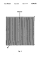
- FIG. 4 is a view of a variable frequency Ronchi grating used in the system shown in FIGS. 1 and 2; the grating having marked lines which provide marker fringes between predetermined rulings (the ruling along the horizontal center line of the grating and the next vertically displaced ruling and rulings eight periods below the marked ruling) so as to enable calibration of a large volume where the object under test might be located.
- FIG. 5A shows a portion of a horizontal window at a height W i ; the window containing a pattern of lines of the calibration grating (FIG. 3) about the center line thereof as imaged on the sensors of the camera.
- FIG. 5B is a curve illustrating the variation in the phase measured at the pixel locations on the right side and left side of the center line, respectively. The correspondence between distance and phase being shown on the ordinate of the curves.
- FIG. 6A is a diagram showing the window illustrated in FIG. 5A with the projected Ronchi grating superimposed thereon and showing the location of the marker fringe along the center line of the Ronchi grating when the calibration target (FIG. 3) is stepped to a certain location, Z n closer to the camera than an initial location of the calibration target at Z 0 .
- FIG. 6B is a curve showing the cumulative phase (the phase measurement at the window to the phase measurement at the marker fringe plus the number of 360° phase transitions therebetween) for each plane at which the calibration grating (FIG. 3) is located, plane Z 0 being furthest from the camera and plane Z 31 being closest to the camera.
- FIG. 7A is a diagram similar to FIG. 6A showing the location of a convolution window which is used to measure the phase in the horizontal direction along a window W i .
- These phase measurements being used for calibration in each of the planes Z 0 to Z n in which the calibration grating (FIG. 3) may be located.
- Z 0 being the plane at the origin with higher numbered planes being successively closer to the camera.
- FIG. 7B is a series of curves showing the cumulative phase between measurements with the convolution window at different pixel positions for each of three successive planes Z 0 , Z 1 and Z 2 ; the remaining planes not being shown to simplify the illustration.
- FIG. 8 is a diagrammatic view in an elevational orientation as shown in FIG. 1.
- FIG. 8 shows the location of the projected Ronchi grating in successive calibration planes Z n and Z n+1 and also showing the location of an intermediate plane. The figure illustrates how the cumulative phase measurements made at the calibration planes may be interpolated to determine the phase measurement and the distance at an intermediate plane between the calibration planes.
- FIG. 9 is a view in a horizontal plane of the calibration planes Z n and Z n+1 and also another calibration plane Z n-1 further from the camera than Z n and showing the location of the surface of the object under test with respect to these planes so as to illustrate how the phase measurements at each pixel location in each plane through a cross-section of the object is mapped to the distance of the object, directly from the phase information using the z calibration information which is plotted in FIG. 7B.
- FIG. 10 is a diagram showing the relationship between absolute phase ( ⁇ ) and unwrapped phase U( ⁇ ) which takes into account successive 360° transitions. The curves show how absolute phase measurements are ambiguous, and how the ambiguity can be removed through the use of unwrapped or cumulative phase.
- FIGS. 11A and B together constitute a functional block diagram of the profilometer system as implemented with the three sets of cameras and projectors which cover successive overlapping aspects of an object under test and the computer system as shown in FIGS. 1 and 2;
- FIGS. 12A, B and C show: in FIG. 12A the images of a cylindrical object of elliptical cross-section imaged at each of three different cameras, 120° apart as shown in FIG. 2; in FIG. 12B the variation in phase in the x direction cross a horizontal window W i ; and in FIG. 12C the distances in the z and x directions into which the phase information is converted through the use of calibration information.
- FIG. 13 is a functional block diagram illustrating in greater detail how the phase calculations are performed in the system illustrated in FIGS. 11A and 11B;
- FIG. 14 is a functional block diagram illustrating the operation of the calibration system to obtain the tables in memory in the system shown in FIGS. 11A and 11B.
- FIGS. 15A, 15B and 15C are functional block diagrams illustrating in greater detail the calibration, marker fringe table generation, and z calibration, respectively.
- a calibration fixture 11 has a calibration target 10 mounted on a stage 12 and 14 which permits the target to be rotated about a vertical axis which is indicated as the "y" axis and translated along the "z" axis.
- the stage includes plates 16 and 18 mounted on a table 14 which provides for rotation.
- the plate 18 is translatable in the z direction.
- the surface of the plate 18 is leveled with reference to gravity.
- the objects for example, may be bodies for which the contour of a cross section is to be determined. These bodies may be moved through the calibrated volume on a conveyor belt which is also leveled to gravity so that the axis of the body is approximately along the y axis.
- the translation stage is designed to enable the calibration target to move through 32 planes, Z 0-31 .
- the 0th plane is through the y axis and the other z planes are a fraction of the period of a line pattern from a Ronchi ruling which is projected on the calibration target.
- This pattern in an exemplary embodiment may have a period of 1/4 inch.
- the translation steps may then suitably be 1/8 inch.
- steps may be equally spaced, their spacing is not critical as long as they are less than half the period of the ruling as projected on the calibration target.
- the resolution of the calibration and also of the profile measurements depends upon the period of the ruling. It has been found that, with a period of approximately 1/4inch, measurement accuracy to ⁇ 0.001 inch is obtainable.
- the calibration target is rotatable to three positions 120° apart as shown in FIG. 2. In each of these positions, the calibration target, which presents a flat surface on which the vertical pattern shown in FIG. 3 appears, is located opposite a projector camera assembly. These assemblies are indicated as PC#1, PC#2 and PC#3 in FIG. 2. All of these assemblies are identical.
- PC#1 includes a video camera which is preferably a charge couple device or CCD camera which has a CCD sensor array. The array may be a matrix of about 320 horizontal and about 250 vertical elements. The video signals from these elements are digitized in a computer system 22 which is connected to the camera 20.
- the video image is digitized into a matrix of 256 horizontal and 240 vertical elements (pixels) as represented by bytes of digitized information from the CCD sensor elements. Each of these elements of digitized information corresponds to a pixel of the field viewed by the array. This field is focused on the array by a lens in the camera. The focus is set to the mean location of the surface being imaged, with a suitable depth of field to cover the calibrated volume. Since the digitized array has 256 pixels in the horizontal direction, the center pixel is 128, the column of 240 pixels along the center (pixel 128 in each row) is aligned with the y axis in the plane of the z axis (the zy plane). Such alignment may be accomplished manually using conventional positioning devices.
- the projectors each include a projector lens which focuses light projected through the variable period Ronchi ruling 26 on the plane of the calibration target. While the optical axis of the camera is aligned with the z axis and is horizontal, the optical axis of the projector is tilted at an acute angle, suitably 45° to the optical axis of the camera.
- the camera optical axis is indicated at 28 and the projector optical axis is indicated at 30. These axes are aligned to be in the z,y plane using the positioning devices.
- the Ronchi ruling 26 is illustrated in greater detail in FIG. 4. It desirably has a variable period. When an inverting projection lens is used, the lines are closer at the top than at the bottom. The variable spacing compensates for the tilt of the projector axis 30 so that the projected lines are parallel and equally spaced on the calibration target 10 when in place or upon objects under test.
- the optimum focus is set for the location of the calibration target surface in the middle of its translation range (at step 16).
- the focus of the camera 20 may be similar.
- the F stop of the projector and camera is selected to provide a depth of field over the entire translation range.
- the Ronchi ruling as shown in FIG. 4 contains at line 33, which extends along the middle of the grating, perpendicular to the constructive center line, an area which provides a marker fringe 34. Also between lines spaced below the center ruling 33 and intersecting the center line is another marker fringe area 36.
- the lower fringe 36 may be eight lines below the center fringe 34.
- the additional marker fringe areas on opposite sides of the lower center line fringe area 36 are indicated at 42 and 44.
- the fringes adjacent to ruling 33 are 75% transmissive, as compared to totally transparent (100% transmissive), the marker fringes 36, 42 and 44 between the lower lines are suitably 85% transmissive.
- the amount of transmissivity and the relationship of the transmissivities of the fringes may be varied or reversed.
- further marker fringes spaced downwardly or upwardly from the center line may be used in order to provide a larger area in the z direction which can be calibrated and used (providing a larger calibrated volume for the object under test).
- the selected transmissivity is provided by a half tone area where the percentage transmissivity is determined by the percentage of the transparent to dark areas of the half tone.
- Another optional means for covering and calibrating over a larger area in the z direction is to use a reduced angle of tilt, for example less than 45° between the optical axes 28 and 30.
- the use of additional marker fringes for covering larger areas is preferred since greater resolution is obtained than would be the case by decreasing the tilt angle.
- Each of the camera projector assemblies PC#1-#3 covers a separate aspect (or view) of the object under test and the calibrated volume; 120° aspects in this embodiment. Each 120° aspect is calibrated separately so as to cover the entire volume.
- FIG. 2 illustrates the Z 0 plane for the aspect viewed by P/C#1, which is along the rotation axis (y) and several of the additional z planes each of which is successively closer to the camera. Exemplary z planes for the other aspects which are viewed by the other camera and projector assemblies are also shown.
- the calibration target is shown in detail in FIG. 3. It has accurate rulings which may be fabricated by a photolithography process on a planar surface, such as a glass plate.
- the lines are suitably 1/8 inch wide black lines separated by a 1/8 inch white space, thereby providing a 1/4 inch period.
- the selection of line spacing is governed by the resolution required, the field of view to be covered, and the receptor matrix in the sensor used. Since the accuracy of the calibration depends upon the precision of the lines, they are desirably made to an accuracy which exceeds the measurement of accuracy of the system, for example an order of magnitude more accurate than the desired measurement accuracy.
- the exemplary target may be a square plate 8 inches on a side.
- the flatness of the ruled surface of the plate is preferably an order of magnitude higher than the resolution of the measurements (e.g., in this case 0.0001 inch). It is desirably mounted in the calibration fixture 11 so that the lines are parallel to the rotation axis.
- the alignment of the camera projector assemblies is facilitated by the outer marker fringes so that the projected ruling pattern at the target will constitute lines which are perpendicular to the lines of the calibration target.
- the alignment is not critical since the calibration process compensates for errors in alignment and also for aberrations in the lenses and sensors of the camera and projector.
- the projector is illuminated by a strobe lamp (not shown) which may be connected to the projector housing by fiber optics.
- a general illumination light source is provided on each camera projector assembly. A typical one of these light sources is a lamp shown at 46. These lamps provide diffuse lighting and illuminate the calibration target. They may be incandescent lamps.
- the projection strobe lamps for each projector and the illumination lamps for each camera are controlled by the computer 22.
- the computer provides horizontal and vertical sync signals to each camera. Separate control lines are provided for the projector strobe lights and the camera constant illumination lights 46.
- the computer also controls the rotation and translation of the stages 12 and 14 by operating stepper motors connected to the stages. These stepper motors and appropriate gearing are not shown to simplify the illustration.
- the computer processes the video information both for calibration and during tests on actual objects (run time).
- the computer system for both calibration and run time is described hereinafter in connection with FIGS. 11-15.
- the calibration process utilizes the calibration target rulings and the projected Ronchi pattern. Their use and the operation of the system during calibration will become more apparent from FIGS. 5-10.
- the system may be compensated for temperature variations as will be explained more fully below. Also in order to minimize the adverse effects of environment, including ambient light, it is desirable that the entire system be enclosed in a chamber. This chamber may be maintained slightly above atmospheric pressure in order to minimize air currents and to exclude dust which might cause optical interference. In the event that the facility in which the system is used is subject to vibration, it is also desirable to mount the entire system on a table which is isolated for vibration. It is also desirable to avoid large temperature changes (e.g., greater than ⁇ 5° F.); smaller changes are accommodated by a temperature control function described hereinafter. The system may be enclosed in a chamber which is temperature controlled to prevent such large temperature changes.
- calibration is carried out to map the relationship of phase and distance in a plurality of planes (the z planes) which extend between the rotation axis and the cameras.
- These maps contain the phase and distance relationships at a plurality of different heights in the y direction.
- Each height may be considered to include a window which extends in the horizontal direction.
- the calibration is carried out first using the calibration target alone illuminated with the constant illumination from the respective lamps 46.
- a phase measurement is then made from which the distances in the x direction from the center of the vertical lines on the calibration target is obtained.
- Distance is correlated to the positions of the pixels across the row, i.e., the distance of each pixel from the center pixel. Because the vertical lines of the calibration pattern have a predetermined spacing (1/4 inch in this example), the phase measurements are also directly correlated with distance.
- Each window contains 32 data points, which again may be increased or decreased as desired.
- the Ronchi ruling with the marker fringes is projected onto the calibration target by flashing the strobe lamp.
- the relative position of the window W i with respect to the marker fringe is determined. Any other one of the horizontal windows may alternatively be used. This is done by storing phase information as to the location of the marker fringe and phase information as to the location of the window plus the number of lines of the projected pattern (horizontal lines) between the marker fringe and the window. This number of lines is determined by counting the cycles of 360° of phase variation between the marker fringe and the window. It will be appreciated that the marker fringe location is indicated by a dip in the pattern of intensity variation along the vertical or y direction. This pattern would normally be sinusoidal because of the equally spaced lines of the projected grating.
- the 75% and 85% fringes can be discriminated by the difference in the amplitude of the intensity variations.
- the fringe 34 at the center of the projected pattern may move out of the field of view. This may occur at planes close to the camera. Then the other fringe 36 will appear. Since it is of different transmissivity, the detection thereof can be used in place of the central marker fringe 34 merely by adding the phase displacement corresponding to the number of lines of separation between the fringes 34 and 36. In this example there are eight lines or 8 times 360° of phase displacement.
- Absolute phase information between the marker fringe and the window is measured in unwrapped phase.
- the meaning of unwrapped phase will be apparent from FIG. 10.
- the sawtooth curves indicated by the dash lines marked ⁇ represents absolute phase versus distance.
- phase varies 360°.
- Unwrapped phase as indicated by the line marked U( ⁇ ) is the unwrapped phase.
- the 360° cycles of phase variation are cumulative; thus as the distance along the projected ruling between the location of the marker fringe and the location of the window increases, the unwrapped phase will increase. For example, consider the absolute phase over the distance indicated as ⁇ x in the figure. ⁇ x starts at 315°, passes through 360°, and continues for another 45°.
- ⁇ x is ambiguous because of the transition in the absolute measurement.
- unwrapped phase the ambiguity is removed.
- the unwrapped phase measurement is 360° plus 45° or 405°.
- the absolute phase measurement is only 45°, and this measurement is ambiguous as to the location of the ⁇ x interval with respect to x.
- phase number corresponding exactly to the plane is obtained.
- This phase number corresponds exactly to distance in the z direction since the phase number for phase Z 0 corresponds to the plane at the axis of rotation (the vertical axis through the origin--see FIG. 1--which is the axis about which the stage 12 rotates).
- the phase number for the plane Z 1 corresponds to a plane 1/8 inch away from the axis in the z direction
- the phase number for the plane Z 2 corresponds to a plane 1/4 inch from the axis of rotation and so forth.
- a table of the phase numbers therefore precisely locates all of the planes in the z direction.
- Maps calibrating each of these z planes in terms of the phase at each calibrated pixel position along the window are obtained by making absolute phase measurements at each pixel position. This phase is compared to the phase found for that pixel at the preceding plane. The difference accumulated, is referred to as Z-calibration.
- These illuminated pixel positions are those pixels between the vertical lines on the calibration target. Not every pixel is measured, because for some, the projected ruling pattern is of low visibility due to the dark rulings on the flat calibration surface of the target 10. In general, due to perspective effect, the pixel at which the phase is determined is not the pixel at which the calibration values are stored. By a linear interpretation of adjacent phases, the phase at the calibration pixel may be found.
- Maps of phase measurements are made taking into account the phase measurements at the Z 0 plane. At Z 0 there is no preceding plane. The phase map thus originates there. Each calibration pixel phase (recall this may be interpreted from the phase of adjacent pixels) begins as an offset from the center phase (phase at pixel 128). This compensates for aberration and distortion in the optics and sensors (cameras, etc.). The center phases are taken as zero at the Z 0 plane and constitute the link between the marked fringe array and the Z-calibration array.
- FIG. 5A Shown is the calibration procedure used to calibrate window W i of plane Z n .
- W i There are 32 calibration windows, W i , at each Z plane. These are the lines about the center line or pixel 128 as viewed by the camera.
- a convolution window one pixel wide in the y direction and 25 pixels long in the x direction is moved both to the right and to the left of the center line.
- phase measurements relating the pixels along the row encompassed by the window are shown in FIG. 5B in terms of unwrapped phase.
- each cycle of unwrapped phase corresponds to a 1/4 inch (the distance between the centers of the white spaces between the lines)
- there is a direct correlation in the x direction between phase and distance are stored in a separate region of computer memory for each plane, Z 0 -Z 31 .
- the x calibration as shown in FIGS. 5A and B is carried out under constant illumination and before the projector strobe is illuminated to project the Ronchi pattern onto the calibration target.
- FIG. 6A shows the portion of the window and also the portion of the pattern projected on the camera having the marker fringe 34.
- the total cumulative phase from the position of the marker fringe y mf to the position of the window y wi is ⁇ mf.
- Total cumulative phase varies in each plane, Z n .
- This cumulative phase takes into account the number of lines of the projected pattern between the marker fringe and the window.
- the phase measurements are made using a convolution window 1 pixel wide in the x direction and 25 pixels wide in the y direction. The spacing between lines will encompass at least 3 pixels.
- the convolution window moves upwardly from y mf to the position of the window y wi , there will be a sinusoidal variation in phase with each period of such variation corresponding to movement of the window a distance equal to the period between lines of the projected pattern.
- the cumulative phase is determined. This cumulative phase is stored for each Z n plane in the z direction (Z 0 to Z 31 ) and correlates the distance of these planes from the rotation axis to the phase measurements.
- FIG. 8 shows how the position of the marker fringe with respect to the window varies in the different planes.
- Two planes are shown Z n and Z n+1 , Z n+1 being the plane adjacent to Z n which is closer to the camera.
- the marker fringe 34 is shown, it will be appreciated that in some cases, particularly in planes close to the camera, the lower marker fringe 36 will be used and the unwrapped phase corresponding to the 8 cycles (8 lines) between these marker fringes 34 and 36 will be taken into account in the stored value of ⁇ mf .
- FIG. 6B shows the variation in cumulative phase ⁇ mfzn with the planes as the planes move closer to the camera.
- the plane at the origin Z has a certain cumulative phase. This phase continues and then reverses as the location of the marker fringe moves to the opposite side of the window W i .
- FIG. 8 there is shown also between the Z n and Z n+1 planes, a plane indicating the location of the surface of an object or part under test as would be the case during the run time after calibration.
- the plane of FIG. 8 is taken through the center line (a plane including the axis of rotation and the optical axes) so that pixel 128 will be intersected by this plane. This pixel is indicated at p 128 in FIG. 8.
- the measurement of cumulative phase is ⁇ mfp is proportional to the distance from the origin of the Z n and Z n+1 planes.
- the phase measurements correlate to this distance in accordance with the following relationships which define the depth between the Z n and Z n+1 planes (%Z)
- the size of the step ( ⁇ Z) is 1/8 inch.
- Z n is the size of the step times the number of the plane from the origin.
- FIG. 7A only the pattern of the calibration target (vertical bars) and the projected pattern (horizontal bars) in the vicinity of the center line (pixel 128) is shown.
- the calibration bars are marked “etched lines” and the lines of the projected pattern are marked “projected lines” in FIG. 7A.
- the Z 0 plane is calibrated. This is accomplished by moving the convolution window and making phase measurements at the pixel positions which are exposed between the etched lines. In FIG. 7A these are pixel positions 116, 122, 128, 134 and 140 for plane Z n . It is noted that these pixel locations will vary with plane number, as consequence of parallax.
- Absolute phase measurements are made by the synchronous detection process which is discussed in the above-identified article by Womack and will be discussed further below in connection with the computer operations.
- the phase measurements are cumulative phase with respect to the Z 0 plane and the phase measurements in the Z 0 plane are taken into account in the cumulative phase measurements for all of the other 31 z planes in each 120° aspect. By taking into account these phase measurements, misalignments and aberrations are automatically compensated.
- the phase information for the Z 0 plane may be stored in terms of the difference in the phase measurements at the pixel positions outward from the pixel 128 along the center line to the phase at pixel 128.
- the phase measurements at each of these pixels would be 0.
- the phase measurements can vary. Therefore the value stored for phase at each pixel position will vary to accommodate these misalignments and aberrations.
- unwrapped phase was discussed in connection with FIG. 10 above.
- FIG. 7B illustrates how the cumulative phase values changes as the planes come closer to the camera in the pixel positions 116, 122, 128, 134 and 140 about the center of the sensor array.
- the curvatures take into account lens and sensor aberrations and characteristics, parallax errors and alignment errors.
- the Z-calibration phase values are used directly by interpolation to locate the surface of an object as shown in FIG. 9 wherein the surface of a part is depicted passing through plane Z n-1 , Z n and Z n+1 .
- the absolute distance calculation for each of these pixels can be calculated from the cumulative (unwrapped) phase difference in accordance with the following relationships, wherein x is the pixel number where the Z distances is to be measured, ⁇ x is the phase at the pixel x, ⁇ x-1 is the phase at the x-1 pixel adjacent to the x pixel, P is the cumulative phase to plane Z n (just before--further from the camera than--the unknown distance), P' is the cumulative phase to plane Z n+1 (just after the unknown distance), P x-1 is the cumulative phase in the x direction at the x-1 pixel, P x is the cumulative phase in the x direction at the x pixel, Z and Z' are the distances from the origin of the calibration planes which stra
- the absolute distance at Z 129 may be determined using the following calculations.
- the computer operates by strobing each of the projectors in each of the three camera projector assemblies in succession.
- the camera input is then digitized in a 256 by 240 byte array.
- Each byte has 8 bits to indicate the gray level (variations in intensity).
- the control function of strobing and digitization of the CCD arrays is indicated by the block 100.
- the computer stores the arrays from each of the 3 cameras in an area of 512 bytes by 512 bytes in a video memory section of the computer memory. This storage may be in random access memory (RAM) in the computer memory.
- RAM random access memory
- the storage arrays for each camera (1-3) is indicated by block 102.
- the video camera sees a pattern such as indicated under #1 in FIG. 12A.
- Cameras #2 and #3 which are 120° apart have imaged thereon patterns shown under #2 and #3 in FIG. 12A.
- the calibration window which was referred to in FIGS. 5A, 6A and 7A is indicated at W i by way of example. The obtaining of the profile of the object at a cross-section perpendicular to the axis of the object which includes the window W i will be explained. It will be appreciated that this window may be one of several, if the entire surface profile of the object is to be derived.
- Each camera utilizes a similar phase calculation and distance conversion subsystem 104, 106 and 108.
- the subsystem 104 for camera #1 is shown in detail.
- the marked fringe is first located using the bytes stored in the array for camera #1 in the video memory 102.
- the bytes are scanned along the column containing pixel 128 and the variations in gray level (intensity) vary sinusoidally except in the area of the marked fringe.
- the row containing the marked fringe location is located and flagged.
- the fringe is removed by scaling the gray level of the byte representing the marked fringe so that the bytes along pixel 128 will vary sinusoidally in amplitude.
- the marked fringe is removed; however, it need not be removed, if it is not located in the window which includes the cross-section at which profile measurements are being made. If any of the other marked fringes are in any of the cross-sections, their gray level is scaled to restore the variation intensity and eliminate the effect of the marked fringe.
- phase at the marked fringe and the phase of the pattern at the window are determined.
- FIG. 6A and 8 above explained in general how this phase was measured and used to determine the phase at the object and convert that phase measurement to distance using equations (1) and (2).
- FIG. 13 illustrates the spatial synchronous detection phase measurement in general at a pixel location indicated as pixel (x, y,).
- the video memory 102 is used.
- the bytes contained in a window centered at pixel x,y are extracted.
- the window is vertical and may be one pixel wide by 25 pixels long.
- the window runs horizontally.
- the bytes in the window are indicated by block 110.
- the pixels in the window are convolved with sine and cosine attenuated functions which are stored in a cosine function memory and a sine function memory 114 and 116.
- the functions stored in these memories are obtained by selection of the convolution window width, the period of sinusoidal activity within the window, and a low pass filter function (e.g., Blackman or Blackman-Harris). As indicated above, a 25 pixel width is used; however, the width may vary depending upon the resolution requirements.
- the period of the pixels in the window are then known because of the period of the rulings in the projected grating. For example with the grating discussed above, there are generally 21/2 to 31/2 periods of the sinewave in a 25 pixel window.
- sine and cosine functions are generated which are pure sine and cosines. These functions are multiplied by a digital filter function.
- the Womack article describes the use of Hamming filter function. It has been found that a Blackman filter or Blackman-Harris function is preferable.
- the cosine function and low pass filter generation processes provide the filtered sine and cosine functions which are stored in the memories 114 and 116 and are convolved with the bytes representing the pixels in the window 110. These are convolutions Ml and M2.
- M1 is the convolution of the pixel information shown at 110 which is extracted from the video memory 102 with the filtered cosine function.
- the other convolution, M2 is with the Blackman filtered sine function.
- the phase is determined by taking the arc tangent of these convolutions as discussed in the Womack article. This phase value is stored and represents the phase at pixel x, y. In this manner, the phase at the location of the marker fringe and at the location of the window for pixel 128 is determined.
- This absolute phase is converted into cumulative phase by measuring the number of 360° transitions in phase between the marked fringe location and the window location. This is determined by the number peaks in the values of the intensity levels along the pixel 128 column. Using this cumulative phase information and the table which correlates cummulative phase of the marked fringes at each of the 32 planes Z 0 to Z 31 , the numbers of the calibration planes between which the center of the surface of the object is located as well as the distance in the z direction from the origin Z 0 ) is determined.
- the marked fringe table is obtained during calibration by phase measurements upon the calibration target as shown in FIG. 15B and as discussed above in connection with FIGS. 6A and 8.
- the marked fringe is located. Then a gray level scaling is applied to the pixels in the column along the center line to remove the modulation and intensity variation due to the marked fringe. From the remaining sinusoidal phase information, the cumulative phase from the marked fringe to the window is measured. This is the phase ⁇ mf. For each of the z planes, the ⁇ mf value is stored. These values are used to determine between which calibration planes (straddling Z planes) the image of the surface of the object at the center of the camera array lies.
- phase at all of the pixel positions in the window on both sides of the center pixel column is calculated using the synchronous detection technique discussed above. This provides phase values at each of the pixel positions x. This variation in phase for the image viewed by camera 3, as shown in FIG. 12A, is shown in FIG. 12B. These phase measurements are converted into absolute distance measurements utilizing the x and z calibration tables as explained in connection with FIG. 9.
- each of the 32 calibration planes has 32 by 32 x values; thus generating the 32 by 32 by 32 matricies discussed earlier.
- each 32 by 32 matrix may be considered to be a separate look-up table; thus for each camera there are 32 x distance look-up tables and 32 z phase look-up tables.
- FIG. 15C shows how the z phase information at a window in a calibration plane is obtained.
- the phase is measured at the center pixel p c (pixel 128) and then at each calibration point. It will be noted that these calibration points may not necessarily be equally spaced at 6 pixels from the center due to the bars of the calibration target pattern. If a bar blocks the calibration point, the phase is measured at a unblocked point and interpolated back to the calibration point. Then an unwrapped phase difference calculation is made to develop the table of 32 values of z phase at the window W i for the base plane.
- the phase measurements at each calibration point in the base plane Z 0 is then used for developing the z phase values in the next reference plane, Z 1 .
- the temporary memory stores the phase values in the preceeding planes so that unwrapped phase difference from the previous planes phase can be determined.
- the phase values are obtained by adding the phase difference in unwrapped phase from the previous plane to the phase values in the previous plane for each of the 32 calibration values in the x direction.
- FIG. 15C shows how the z phase values are obtained in the Z 0 plane as well as the z phase values for the same window in each of the other calibration planes.
- the total calibration operation is illustrated in FIG. 14.
- the calibration target is illuminated with the constant or uniform illumination from the incandescent light sources 46; the projectors of the Ronchi pattern being off.
- x-calibration is carried out for all windows in the first, Z 0 calibration plane.
- the projector is strobed and the marked fringe table is generated for all windows in the Z 0 plane.
- the video memory has sufficient information to obtain the z phase calibration for all windows in the Z 0 plane.
- the stepper motor is turned on and the Z 1 plane is calibrated.
- the stepper motor steps the calibration target to the Z 2 and that plane is calibrated.
- the calibration target is rotated 120° to face the next camera projector assembly and reindexed back to the Z 0 position.
- the planes are recalibrated for the new camera/projector array.
- the calibration target is rotated another 120° to face the third camera projector array and the 32 planes are again calibrated. All of the calibration information is stored in the tables.
- the calibration target can then be removed and the system used for object profilometry in three dimensions. Once the system is calibrated, it may be recalibrated from time to time depending upon changes in alignments which may occur during use. For example in installations subject to vibration or other changes which may affect the positioning of the elements, recalibration may be needed more frequently than otherwise would be the case.
- phase measurements are converted into x and z distance measurements using the x and z phase tables as explained in connection with FIG. 9.
- %Z %p 128 which is the center pixel in the window.
- an interpolation program in z and x may be used to obtain the calibrated values in the z planes for the intermediate pixel positions.
- the distance conversion thus provides a family of x and z values at any cross-section of the object under test or at a plurality of cross-sections if more than one cross-section is to be measured.
- the object under test is imaged onto a number of pixels, there will be a number of x and z values in each aspect.
- the number of X 1 and Z 1 values equal to the number of pixels in camera #1 on which the object is imaged.
- X 2 and Z 2 values and X 3 and Z 3 values corresponding to the number of pixels in the second and third cameras on which the object is imaged.
- the offsets are corrections that are used in merging the three cameras' coordinate systems.
- the offsets are measured through the use of a reference object, when the measurements are designed to compare the measured values with a standard.
- the standard object is then measured and the offsets from the known standard are stored in an offset table. This standard is referred to as a golden master and is measured at a reference time and temperature.
- the offset values are indicated as ⁇ X off and ⁇ Z off .
- the temperature change is also an offset.
- the temperature can be detected by the use of a target which remains in the system.
- This target has a pattern of lines similar to that of the calibration target but may be smaller, since only a phase measurement at a pixel position near the top of the CCD sensor array is used.
- This may be pixel 128 in row 12, or closer to the top if a smaller convolution window is used.
- the pixel used may be that closest to P 128 in row 12 which is at the intersection of bright areas between the projected grating and the temperature target ruling.
- Both the x and z measurements at this pixel position are used as an offset and added to the standard offset in an offset accumulator for each of the three aspects, with the offsets added to the values of x and z (or subtracted as the case may be) to provide new values X' 1 , Z' 1 ; X' 2 , Z' 2 ; and X' 3 , Z' 3 .
- the X' 2 , Z' 2 and X' 3 , Z' 3 values are given +120° and -120° coordinate transformations, respectively. There are therefore a succession of x and z values for successive locations 360° about the cross-section. These x and z values are stored in memory.
- a measurement of greater than 1/8 inch corresponds to a phase ambiguity and is considered aberrated data. If the data does not change monotonically (either increasing or decreasing), the probability is that the data is aberrated. Such data points are also removed. It may also be desirable, optionally and especially where the centroid of a cross-section is to be computed from the data, to remove any redundant data point. This will provide only data in the areas which do not overlap.
- the output data represents the cross-section of the object. It can be compared to standard cross-sections, either in area or along particular radii for the purpose of inspection and acceptance of parts.
- the distance measurements may also be used to provide machine vision inputs to robot arms which must move precisely with respect to the objects under test.
- phase measurements may be made using temporal synchronous detection rather than spatial synchronous detection, for example translating the projected grating and measuring the relative phase shifts at each translation. Accordingly the foregoing description should be taken as illustrative and not in a limiting sense.
Abstract
Description
%Z=(φmfz-φmfp)/(φmfz.sub.n -φmfz.sub.n+1)
Z=Z.sub.n +%Z (ΔZ). (2)
U (Δφ)=U (φ.sub.x -φ.sub.x-1) (3)
P.sub.x =P.sub.x-1 +U (Δφ) (4)
%p.sub.x =(P-p.sub.x)/(P-P') (5)
Z.sub.x =Z+%p.sub.x (Z-Z') (6)
U (Δφ)=U (φ.sub.129 -φ.sub.128) (7)
p.sub.129 =p.sub.128 +U (Δφ) (8)
%p.sub.129 =(P-p.sub.129)/P-P') (9)
Z.sub.129 =Z+%p.sub.129 (Z-Z') (10)
%Z=(φmfz-φmfp)/(φmfz.sub.n -φmfz.sub.n +1) (1)
(viz., ΔZ=Z-Z'=Z.sub.n -Z.sub.n+1) (2)
p128=P+%Z (P'-P) (3)
U (Δφ)=U(φ.sub.x -φ.sub.x-1) (4)
Px-p.sub.x-1 U (Δ0) (5)
%p.sub.x =(P-p.sub.x)/(P-P') (6)
Z.sub.x =Z+%px (Z-Z') (7)
Claims (35)
Priority Applications (4)
| Application Number | Priority Date | Filing Date | Title |
|---|---|---|---|
| US07/045,110 US5085502A (en) | 1987-04-30 | 1987-04-30 | Method and apparatus for digital morie profilometry calibrated for accurate conversion of phase information into distance measurements in a plurality of directions |
| DE3813692A DE3813692A1 (en) | 1987-04-30 | 1988-04-22 | METHOD AND DEVICE FOR DIGITAL MOIREPROFILOMETRY, CALIBRATED FOR THE ACCURATE CONVERSION OF PHASE INFORMATION IN DISTANCE MEASUREMENTS IN A VARIETY OF DIRECTIONS |
| GB8809852A GB2204397B (en) | 1987-04-30 | 1988-04-26 | Method and apparatus for digital moire profilometry calibrated for accurate conversion of phase information into distance measurements in a plurality of dire |
| FR8805820A FR2614691A1 (en) | 1987-04-30 | 1988-04-29 | PROFILE MEASUREMENT APPARATUS, BY DIGITAL MOIRE TECHNIQUE, CALIBRATED TO ALLOW A PRECISE CONVERSION OF PHASE INFORMATION INTO DISTANCE MEASUREMENTS FOLLOWING SEVERAL DIRECTIONS |
Applications Claiming Priority (1)
| Application Number | Priority Date | Filing Date | Title |
|---|---|---|---|
| US07/045,110 US5085502A (en) | 1987-04-30 | 1987-04-30 | Method and apparatus for digital morie profilometry calibrated for accurate conversion of phase information into distance measurements in a plurality of directions |
Publications (1)
| Publication Number | Publication Date |
|---|---|
| US5085502A true US5085502A (en) | 1992-02-04 |
Family
ID=21936048
Family Applications (1)
| Application Number | Title | Priority Date | Filing Date |
|---|---|---|---|
| US07/045,110 Expired - Fee Related US5085502A (en) | 1987-04-30 | 1987-04-30 | Method and apparatus for digital morie profilometry calibrated for accurate conversion of phase information into distance measurements in a plurality of directions |
Country Status (4)
| Country | Link |
|---|---|
| US (1) | US5085502A (en) |
| DE (1) | DE3813692A1 (en) |
| FR (1) | FR2614691A1 (en) |
| GB (1) | GB2204397B (en) |
Cited By (65)
| Publication number | Priority date | Publication date | Assignee | Title |
|---|---|---|---|---|
| US5345866A (en) * | 1992-04-25 | 1994-09-13 | Koenig & Bauer Aktiengesellschaft | Doctor blade bar assembly |
| US5345867A (en) * | 1992-04-25 | 1994-09-13 | Koenig & Bauer Aktiengesellschaft | Doctor blade bar assembly |
| US5379107A (en) * | 1992-05-29 | 1995-01-03 | Carl-Zeiss-Stiftung | Process and apparatus for the measurement of object topographies by means of projected fringe patterns |
| US5557410A (en) * | 1994-05-26 | 1996-09-17 | Lockheed Missiles & Space Company, Inc. | Method of calibrating a three-dimensional optical measurement system |
| US5636025A (en) * | 1992-04-23 | 1997-06-03 | Medar, Inc. | System for optically measuring the surface contour of a part using more fringe techniques |
| US5691815A (en) * | 1996-01-02 | 1997-11-25 | Lockheed Missiles & Space Co., Inc. | Laser inspection tool system |
| US5757500A (en) * | 1995-09-07 | 1998-05-26 | Virtek Vision Corp. | Calibration system for large tooling fixtures |
| EP0877914A1 (en) * | 1996-01-29 | 1998-11-18 | Medar, Inc. | Scanning phase measuring method and system for an object at a vision station |
| WO1998055826A2 (en) * | 1997-06-05 | 1998-12-10 | Electronic Packaging Services, Ltd. Co. | Measuring surface flatness using shadow moire technology and phase-stepping image processing |
| WO2000003198A1 (en) * | 1998-07-08 | 2000-01-20 | Ppt Vision, Inc. | Machine vision and semiconductor handling |
| US6055056A (en) * | 1996-05-06 | 2000-04-25 | Fraunhofer-Gesellschaft Zur Foerderung Der Angewandten Forschung E.V. | Device for non-contact measurement of the surface of a three dimensional object |
| US6252623B1 (en) * | 1998-05-15 | 2001-06-26 | 3Dmetrics, Incorporated | Three dimensional imaging system |
| US6331848B1 (en) * | 1996-04-27 | 2001-12-18 | U.S. Philips Corporation | Projection display system |
| EP1170572A2 (en) * | 2000-06-30 | 2002-01-09 | Thermo Radiometrie Oy | Apparatus and method for determining surface shapes |
| US20020006217A1 (en) * | 2000-04-28 | 2002-01-17 | Orametrix, Inc. | Methods for registration of three-dimensional frames to create three-dimensional virtual models of objects |
| WO2002010679A1 (en) * | 2000-07-28 | 2002-02-07 | Yamatake Corporation | Surface shape measuring system |
| US6359680B1 (en) * | 1996-09-13 | 2002-03-19 | Orametrix, Inc. | Three-dimensional object measurement process and device |
| US6438272B1 (en) * | 1997-12-31 | 2002-08-20 | The Research Foundation Of State University Of Ny | Method and apparatus for three dimensional surface contouring using a digital video projection system |
| US6456384B1 (en) | 2000-11-09 | 2002-09-24 | Tropel Corporation | Moiré interferometer with overlapping illumination and imaging systems |
| US20020171847A1 (en) * | 2001-04-27 | 2002-11-21 | Tadashi Fukumoto | Three-dimensional shape-measuring system |
| US6486963B1 (en) | 2000-06-20 | 2002-11-26 | Ppt Vision, Inc. | Precision 3D scanner base and method for measuring manufactured parts |
| US6488390B1 (en) | 1998-03-19 | 2002-12-03 | Ppt Vision, Inc. | Color-adjusted camera light and method |
| US6501554B1 (en) | 2000-06-20 | 2002-12-31 | Ppt Vision, Inc. | 3D scanner and method for measuring heights and angles of manufactured parts |
| US6504605B1 (en) | 2000-10-24 | 2003-01-07 | The Regents Of The University Of California | Method and apparatus for determining the coordinates of an object |
| US6509559B1 (en) | 2000-06-20 | 2003-01-21 | Ppt Vision, Inc. | Binary optical grating and method for generating a moire pattern for 3D imaging |
| WO2003014665A1 (en) * | 2001-08-01 | 2003-02-20 | Unilever N.V. | Device and method for 3d imaging |
| US6547397B1 (en) | 2000-04-19 | 2003-04-15 | Laser Projection Technologies, Inc. | Apparatus and method for projecting a 3D image |
| US20030096210A1 (en) * | 1999-11-30 | 2003-05-22 | Orametrix, Inc. | Interactive orthodontic care system based on intra-oral scanning of teeth |
| US20030193658A1 (en) * | 1998-05-25 | 2003-10-16 | Kenya Uomori | Ranger finder device and camera |
| US6788411B1 (en) | 1999-07-08 | 2004-09-07 | Ppt Vision, Inc. | Method and apparatus for adjusting illumination angle |
| US20040246497A1 (en) * | 2001-09-26 | 2004-12-09 | Jean-Pierre Chambard | Method and device for measuring at least a geometric quantity of an optically reflecting surface |
| US20040256368A1 (en) * | 2002-12-24 | 2004-12-23 | Eo Technics Co., Ltd. | Chip scale marker and method of calibrating marking position |
| US20050021285A1 (en) * | 2003-06-17 | 2005-01-27 | Troxler Electronic Laboratories, Inc. | Method of determining a dimension of a sample of a construction material and associated apparatus |
| US20050022213A1 (en) * | 2003-07-25 | 2005-01-27 | Hitachi, Ltd. | Method and apparatus for synchronizing applications for data recovery using storage based journaling |
| US20050029168A1 (en) * | 2003-08-01 | 2005-02-10 | Jones William J. | Currency processing device, method and system |
| US20050111726A1 (en) * | 1998-07-08 | 2005-05-26 | Hackney Joshua J. | Parts manipulation and inspection system and method |
| US7023559B1 (en) | 1999-07-14 | 2006-04-04 | Solvision Inc. | Method and system for measuring the relief of an object |
| US20060072123A1 (en) * | 2003-01-25 | 2006-04-06 | Wilson John E | Methods and apparatus for making images including depth information |
| US20060077400A1 (en) * | 2004-10-13 | 2006-04-13 | Akrometrix, Llc | Systems and methods for measuring sample surface flatness of continuously moving samples |
| US20060103853A1 (en) * | 2004-11-12 | 2006-05-18 | The Boeing Company | Optical projection system |
| US20070075997A1 (en) * | 2005-09-22 | 2007-04-05 | Janos Rohaly | Artifact mitigation in three-dimensional imaging |
| US20070146727A1 (en) * | 2000-03-24 | 2007-06-28 | Solvision Inc. | System for simultaneous projections of multiple phase-shifted patterns for the three-dimensional inspection of an object |
| WO2008017878A2 (en) * | 2006-08-11 | 2008-02-14 | The University Of Leeds | Optical imaging of physical objects |
| US20080075328A1 (en) * | 2006-09-15 | 2008-03-27 | Sciammarella Cesar A | System and method for analyzing displacements and contouring of surfaces |
| US7353954B1 (en) | 1998-07-08 | 2008-04-08 | Charles A. Lemaire | Tray flipper and method for parts inspection |
| US7525669B1 (en) * | 2004-07-09 | 2009-04-28 | Mohsen Abdollahi | High-speed, scanning phase-shifting profilometry using 2D CMOS sensor |
| US20090185800A1 (en) * | 2008-01-23 | 2009-07-23 | Sungkyunkwan University Foundation For Corporate Collaboration | Method and system for determining optimal exposure of structured light based 3d camera |
| US20100295941A1 (en) * | 2009-05-21 | 2010-11-25 | Koh Young Technology Inc. | Shape measurement apparatus and method |
| US20110026014A1 (en) * | 2009-07-31 | 2011-02-03 | Lightcraft Technology, Llc | Methods and systems for calibrating an adjustable lens |
| ITBI20090007A1 (en) * | 2009-09-11 | 2011-03-12 | Mego Roberto Ganio | ADJUSTABLE INTERFACE DEVICE FOR ROTARY AXIS CALIBRATION INSTRUMENT. |
| WO2012056724A1 (en) * | 2010-10-29 | 2012-05-03 | 富士フイルム株式会社 | Phase contrast radiation imaging device |
| US8320031B1 (en) * | 2009-12-10 | 2012-11-27 | The Boeing Company | Method for real time holographic fringe blazing by determining adjacent fringe minima and blazing intermediate the minima |
| US20130004082A1 (en) * | 2011-06-28 | 2013-01-03 | Sony Corporation | Image processing device, method of controlling image processing device, and program for enabling computer to execute same method |
| US8643305B2 (en) | 1998-03-19 | 2014-02-04 | Lemaire Illumination Technologies, Llc | Apparatus for L.E.D. illumination |
| US20140253929A1 (en) * | 2011-10-18 | 2014-09-11 | Nanyang Technological University | Apparatus and method for 3d surface measurement |
| CN104215200A (en) * | 2013-04-30 | 2014-12-17 | 埃梅斯服务有限责任公司 | Device and method for the simultaneous three-dimensional measurement of surfaces with several wavelengths |
| US9273951B2 (en) | 2011-06-06 | 2016-03-01 | Troxler Electronic Laboratories, Inc. | Optical method and apparatus for determining a characteristic such as volume and density of an excavated void in a construction material |
| US9587938B2 (en) | 2003-06-17 | 2017-03-07 | Troxler Electronic Laboratories, Inc. | Method and apparatus for determining a characteristic of a construction material |
| US10209698B2 (en) | 2014-12-26 | 2019-02-19 | Industrial Technology Research Institute | Calibration method and automation machining apparatus using the same |
| CN109724531A (en) * | 2018-10-18 | 2019-05-07 | 苏州光图智能科技有限公司 | 360 ° of contour measuring methods |
| US10571585B2 (en) | 2016-08-31 | 2020-02-25 | Chevron U.S.A. Inc. | System and method for time-lapsing seismic imaging |
| US10580123B2 (en) | 2016-03-22 | 2020-03-03 | Fraunhofer-Gesellschaft Zur Förderung Der | Device and method of combining measurement signals from illumination signals |
| US20200232789A1 (en) * | 2017-02-20 | 2020-07-23 | Siemens Aktiengesellschaft | Devices and Methods for Calibrating a Measuring Apparatus Using Projected Patterns |
| US11143499B2 (en) * | 2018-09-18 | 2021-10-12 | Electronics And Telecommunications Research Institute | Three-dimensional information generating device and method capable of self-calibration |
| CN114459383A (en) * | 2022-02-28 | 2022-05-10 | 嘉兴市像景智能装备有限公司 | Calibration method based on sine stripe phase shift profilometry and implementation device |
Families Citing this family (12)
| Publication number | Priority date | Publication date | Assignee | Title |
|---|---|---|---|---|
| DE3907430C1 (en) * | 1988-12-23 | 1991-03-21 | Klaus 8206 Bruckmuehl De Pfister | |
| CH677972A5 (en) * | 1989-01-17 | 1991-07-15 | Kern & Co Ag | |
| DE4007502A1 (en) * | 1990-03-09 | 1991-09-12 | Zeiss Carl Fa | METHOD AND DEVICE FOR CONTACTLESS MEASUREMENT OF OBJECT SURFACES |
| DE4011780C1 (en) * | 1990-04-11 | 1991-09-26 | Hans Dr. 8032 Graefelfing De Langer | Scanning surface by projection of modulation pattern - ascertaining coordinates by observing at angle to projection direction line pattern produced when second modulation pattern is projected |
| DE4013283C1 (en) * | 1990-04-26 | 1991-10-02 | Hans Dr. 8032 Graefelfing De Langer | Scanning surface by projecting modulation pattern - observing surface by optics via second modulation pattern at angle to direction of projection |
| DE4017299A1 (en) * | 1990-05-30 | 1991-12-05 | Langer Hans | Distortion-free scanning of surfaces - transforming scan coordinates of surface from central projection to parallel projection |
| JPH05504842A (en) * | 1990-10-24 | 1993-07-22 | ベーラー ゲゼルシャフト ミット ベシュレンクテル ハフツング | Method and device for photoelectrically measuring objects |
| DE4130237A1 (en) * | 1991-09-11 | 1993-03-18 | Zeiss Carl Fa | METHOD AND DEVICE FOR THE THREE-DIMENSIONAL OPTICAL MEASUREMENT OF OBJECT SURFACES |
| FR2696542A1 (en) * | 1992-10-05 | 1994-04-08 | Controle Ind | Optical detector and test system for metrological use - has structured plane light source, diffused light source and a matrix camera in same enclosure |
| GB9420638D0 (en) * | 1994-10-13 | 1994-11-30 | Moore John H | Three-dimensional digitiser |
| AU5270596A (en) * | 1995-03-30 | 1996-10-16 | Pipetech Aps | System identification |
| CN101466998B (en) * | 2005-11-09 | 2015-09-16 | 几何信息学股份有限公司 | The method and apparatus of absolute-coordinate three-dimensional surface imaging |
Citations (17)
| Publication number | Priority date | Publication date | Assignee | Title |
|---|---|---|---|---|
| US4009965A (en) * | 1972-05-15 | 1977-03-01 | Timothy Reed Pryor | Method and apparatus for determining object dimension and other characteristics using diffraction waves |
| US4131365A (en) * | 1974-09-13 | 1978-12-26 | Pryor Timothy R | Method and apparatus for determining object position and dimension using a diffraction wave |
| US4139304A (en) * | 1977-02-10 | 1979-02-13 | National Research Development Corporation | Methods and apparatus for measuring variations in distance to a surface |
| US4340306A (en) * | 1980-02-04 | 1982-07-20 | Balasubramanian N | Optical system for surface topography measurement |
| US4387994A (en) * | 1980-02-04 | 1983-06-14 | Balasubramanian N | Optical system for surface topography measurement |
| US4391526A (en) * | 1981-08-24 | 1983-07-05 | Itek Corporation | Interferometric surface contour measuring arrangement |
| US4452534A (en) * | 1981-09-01 | 1984-06-05 | Gribanov Dmitry D | Method of determining geometric parameters of object's surface and device therefor |
| US4456339A (en) * | 1980-06-16 | 1984-06-26 | The United States Of America As Represented By The United States Department Of Energy | Laser heterodyne surface profiler |
| US4457625A (en) * | 1981-07-13 | 1984-07-03 | Itek Corporation | Self calibrating contour measuring system using fringe counting interferometers |
| US4490617A (en) * | 1979-11-26 | 1984-12-25 | European Electronic Systems Limited | Optical width measuring system using two cameras |
| US4498770A (en) * | 1979-05-29 | 1985-02-12 | Beta Industries, Inc. | Apparatus and method for determining the configuration of a reflective surface |
| US4627734A (en) * | 1983-06-30 | 1986-12-09 | Canadian Patents And Development Limited | Three dimensional imaging method and device |
| US4641972A (en) * | 1984-09-14 | 1987-02-10 | New York Institute Of Technology | Method and apparatus for surface profilometry |
| US4641971A (en) * | 1983-12-27 | 1987-02-10 | International Business Machines Corporation | White light interferometer |
| US4657394A (en) * | 1984-09-14 | 1987-04-14 | New York Institute Of Technology | Apparatus and method for obtaining three dimensional surface contours |
| US4682894A (en) * | 1985-03-21 | 1987-07-28 | Robotic Vision Systems, Inc. | Calibration of three-dimensional space |
| US4752964A (en) * | 1984-04-17 | 1988-06-21 | Kawasaki Jukogyo Kabushiki Kaisha | Method and apparatus for producing three-dimensional shape |
Family Cites Families (5)
| Publication number | Priority date | Publication date | Assignee | Title |
|---|---|---|---|---|
| DE2456585A1 (en) * | 1974-11-29 | 1976-08-12 | Hans Dr Ing Rottenkolber | Object testing method for correctness of shape - is by generation of contour lines by light rays |
| US4269513A (en) * | 1975-08-27 | 1981-05-26 | Solid Photography Inc. | Arrangement for sensing the surface of an object independent of the reflectance characteristics of the surface |
| DE2919863C2 (en) * | 1979-05-17 | 1982-05-06 | Deutsche Forschungs- und Versuchsanstalt für Luft- und Raumfahrt e.V., 5000 Köln | Method and device for recording and displaying the shape or change in shape of the surface of objects |
| DE3205362A1 (en) * | 1982-02-15 | 1983-08-25 | Pfeifer, Tilo, Prof. Dr.-Ing. | Spatial displacement measuring system |
| US4634278A (en) * | 1984-02-06 | 1987-01-06 | Robotic Vision Systems, Inc. | Method of three-dimensional measurement with few projected patterns |
-
1987
- 1987-04-30 US US07/045,110 patent/US5085502A/en not_active Expired - Fee Related
-
1988
- 1988-04-22 DE DE3813692A patent/DE3813692A1/en not_active Ceased
- 1988-04-26 GB GB8809852A patent/GB2204397B/en not_active Expired - Fee Related
- 1988-04-29 FR FR8805820A patent/FR2614691A1/en active Pending
Patent Citations (18)
| Publication number | Priority date | Publication date | Assignee | Title |
|---|---|---|---|---|
| US4009965A (en) * | 1972-05-15 | 1977-03-01 | Timothy Reed Pryor | Method and apparatus for determining object dimension and other characteristics using diffraction waves |
| US4131365A (en) * | 1974-09-13 | 1978-12-26 | Pryor Timothy R | Method and apparatus for determining object position and dimension using a diffraction wave |
| US4139304A (en) * | 1977-02-10 | 1979-02-13 | National Research Development Corporation | Methods and apparatus for measuring variations in distance to a surface |
| US4498770A (en) * | 1979-05-29 | 1985-02-12 | Beta Industries, Inc. | Apparatus and method for determining the configuration of a reflective surface |
| US4490617A (en) * | 1979-11-26 | 1984-12-25 | European Electronic Systems Limited | Optical width measuring system using two cameras |
| US4499383A (en) * | 1979-11-26 | 1985-02-12 | European Electronic Systems Ltd. | Edge detection apparatus |
| US4340306A (en) * | 1980-02-04 | 1982-07-20 | Balasubramanian N | Optical system for surface topography measurement |
| US4387994A (en) * | 1980-02-04 | 1983-06-14 | Balasubramanian N | Optical system for surface topography measurement |
| US4456339A (en) * | 1980-06-16 | 1984-06-26 | The United States Of America As Represented By The United States Department Of Energy | Laser heterodyne surface profiler |
| US4457625A (en) * | 1981-07-13 | 1984-07-03 | Itek Corporation | Self calibrating contour measuring system using fringe counting interferometers |
| US4391526A (en) * | 1981-08-24 | 1983-07-05 | Itek Corporation | Interferometric surface contour measuring arrangement |
| US4452534A (en) * | 1981-09-01 | 1984-06-05 | Gribanov Dmitry D | Method of determining geometric parameters of object's surface and device therefor |
| US4627734A (en) * | 1983-06-30 | 1986-12-09 | Canadian Patents And Development Limited | Three dimensional imaging method and device |
| US4641971A (en) * | 1983-12-27 | 1987-02-10 | International Business Machines Corporation | White light interferometer |
| US4752964A (en) * | 1984-04-17 | 1988-06-21 | Kawasaki Jukogyo Kabushiki Kaisha | Method and apparatus for producing three-dimensional shape |
| US4641972A (en) * | 1984-09-14 | 1987-02-10 | New York Institute Of Technology | Method and apparatus for surface profilometry |
| US4657394A (en) * | 1984-09-14 | 1987-04-14 | New York Institute Of Technology | Apparatus and method for obtaining three dimensional surface contours |
| US4682894A (en) * | 1985-03-21 | 1987-07-28 | Robotic Vision Systems, Inc. | Calibration of three-dimensional space |
Non-Patent Citations (2)
| Title |
|---|
| K. H. Womack, "Interferometic Phase Measurement Using Spatial Synchronous Detection", Optical Engineering, vol. 23, No. 4, p. 391, Jul. Aug. 1984. |
| K. H. Womack, Interferometic Phase Measurement Using Spatial Synchronous Detection , Optical Engineering, vol. 23, No. 4, p. 391, Jul. Aug. 1984. * |
Cited By (125)
| Publication number | Priority date | Publication date | Assignee | Title |
|---|---|---|---|---|
| US5636025A (en) * | 1992-04-23 | 1997-06-03 | Medar, Inc. | System for optically measuring the surface contour of a part using more fringe techniques |
| US5345866A (en) * | 1992-04-25 | 1994-09-13 | Koenig & Bauer Aktiengesellschaft | Doctor blade bar assembly |
| US5345867A (en) * | 1992-04-25 | 1994-09-13 | Koenig & Bauer Aktiengesellschaft | Doctor blade bar assembly |
| US5379107A (en) * | 1992-05-29 | 1995-01-03 | Carl-Zeiss-Stiftung | Process and apparatus for the measurement of object topographies by means of projected fringe patterns |
| US5557410A (en) * | 1994-05-26 | 1996-09-17 | Lockheed Missiles & Space Company, Inc. | Method of calibrating a three-dimensional optical measurement system |
| US5612786A (en) * | 1994-05-26 | 1997-03-18 | Lockheed Missiles & Space Company, Inc. | Contour measurement system |
| US5757500A (en) * | 1995-09-07 | 1998-05-26 | Virtek Vision Corp. | Calibration system for large tooling fixtures |
| US5691815A (en) * | 1996-01-02 | 1997-11-25 | Lockheed Missiles & Space Co., Inc. | Laser inspection tool system |
| EP0877914A1 (en) * | 1996-01-29 | 1998-11-18 | Medar, Inc. | Scanning phase measuring method and system for an object at a vision station |
| USRE39978E1 (en) | 1996-01-29 | 2008-01-01 | Ismeca Europe Semiconductor Sa | Scanning phase measuring method and system for an object at a vision station |
| EP0877914A4 (en) * | 1996-01-29 | 2000-05-31 | Medar Inc | Scanning phase measuring method and system for an object at a vision station |
| US6331848B1 (en) * | 1996-04-27 | 2001-12-18 | U.S. Philips Corporation | Projection display system |
| US6055056A (en) * | 1996-05-06 | 2000-04-25 | Fraunhofer-Gesellschaft Zur Foerderung Der Angewandten Forschung E.V. | Device for non-contact measurement of the surface of a three dimensional object |
| US6359680B1 (en) * | 1996-09-13 | 2002-03-19 | Orametrix, Inc. | Three-dimensional object measurement process and device |
| WO1998055826A2 (en) * | 1997-06-05 | 1998-12-10 | Electronic Packaging Services, Ltd. Co. | Measuring surface flatness using shadow moire technology and phase-stepping image processing |
| WO1998055826A3 (en) * | 1997-06-05 | 1999-03-18 | Electronic Packaging Services | Measuring surface flatness using shadow moire technology and phase-stepping image processing |
| US5969819A (en) * | 1997-06-05 | 1999-10-19 | Electronics Packaging Services Ltd. Co. | Measuring surface flatness using shadow moire technology and phase-stepping image processing |
| US6438272B1 (en) * | 1997-12-31 | 2002-08-20 | The Research Foundation Of State University Of Ny | Method and apparatus for three dimensional surface contouring using a digital video projection system |
| US8829808B1 (en) | 1998-03-19 | 2014-09-09 | Led Tech Development, Llc | Apparatus and method for pulsed L.E.D. illumination |
| US8643305B2 (en) | 1998-03-19 | 2014-02-04 | Lemaire Illumination Technologies, Llc | Apparatus for L.E.D. illumination |
| US9907137B1 (en) | 1998-03-19 | 2018-02-27 | Lemaire Illumination Technologies, Llc | Pulsed L.E.D. illumination |
| US6808287B2 (en) | 1998-03-19 | 2004-10-26 | Ppt Vision, Inc. | Method and apparatus for a pulsed L.E.D. illumination source |
| US20030095406A1 (en) * | 1998-03-19 | 2003-05-22 | Ppt Vision, Inc. | Method and apparatus for a pulsed L.E.D. illumination source |
| US6488390B1 (en) | 1998-03-19 | 2002-12-03 | Ppt Vision, Inc. | Color-adjusted camera light and method |
| US6252623B1 (en) * | 1998-05-15 | 2001-06-26 | 3Dmetrics, Incorporated | Three dimensional imaging system |
| US6897946B2 (en) * | 1998-05-25 | 2005-05-24 | Matsushita Electric Industrial Co., Ltd. | Ranger finder device and camera |
| US20030193658A1 (en) * | 1998-05-25 | 2003-10-16 | Kenya Uomori | Ranger finder device and camera |
| US6603103B1 (en) | 1998-07-08 | 2003-08-05 | Ppt Vision, Inc. | Circuit for machine-vision system |
| US7353954B1 (en) | 1998-07-08 | 2008-04-08 | Charles A. Lemaire | Tray flipper and method for parts inspection |
| US6522777B1 (en) | 1998-07-08 | 2003-02-18 | Ppt Vision, Inc. | Combined 3D- and 2D-scanning machine-vision system and method |
| US8408379B2 (en) | 1998-07-08 | 2013-04-02 | Charles A. Lemaire | Parts manipulation, inspection, and replacement |
| US7397550B2 (en) | 1998-07-08 | 2008-07-08 | Charles A. Lemaire | Parts manipulation and inspection system and method |
| US8286780B2 (en) | 1998-07-08 | 2012-10-16 | Charles A. Lemaire | Parts manipulation, inspection, and replacement system and method |
| US6956963B2 (en) | 1998-07-08 | 2005-10-18 | Ismeca Europe Semiconductor Sa | Imaging for a machine-vision system |
| US7773209B2 (en) | 1998-07-08 | 2010-08-10 | Charles A. Lemaire | Method and apparatus for parts manipulation, inspection, and replacement |
| US20090180679A1 (en) * | 1998-07-08 | 2009-07-16 | Charles A. Lemaire | Method and apparatus for parts manipulation, inspection, and replacement |
| US20090078620A1 (en) * | 1998-07-08 | 2009-03-26 | Charles A. Lemaire | Tray flipper, tray, and method for parts inspection |
| US20050111726A1 (en) * | 1998-07-08 | 2005-05-26 | Hackney Joshua J. | Parts manipulation and inspection system and method |
| US20090073427A1 (en) * | 1998-07-08 | 2009-03-19 | Charles A. Lemaire | Parts manipulation, inspection, and replacement system and method |
| US7719670B2 (en) | 1998-07-08 | 2010-05-18 | Charles A. Lemaire | Parts manipulation, inspection, and replacement system and method |
| WO2000003198A1 (en) * | 1998-07-08 | 2000-01-20 | Ppt Vision, Inc. | Machine vision and semiconductor handling |
| US8056700B2 (en) | 1998-07-08 | 2011-11-15 | Charles A. Lemaire | Tray flipper, tray, and method for parts inspection |
| US7142301B2 (en) | 1999-07-08 | 2006-11-28 | Ppt Vision | Method and apparatus for adjusting illumination angle |
| US7557920B2 (en) | 1999-07-08 | 2009-07-07 | Lebens Gary A | Method and apparatus for auto-adjusting illumination |
| US6788411B1 (en) | 1999-07-08 | 2004-09-07 | Ppt Vision, Inc. | Method and apparatus for adjusting illumination angle |
| USRE42899E1 (en) | 1999-07-14 | 2011-11-08 | Zygo Corporation | Method and system for measuring the relief of an object |
| US7023559B1 (en) | 1999-07-14 | 2006-04-04 | Solvision Inc. | Method and system for measuring the relief of an object |
| US6648640B2 (en) | 1999-11-30 | 2003-11-18 | Ora Metrix, Inc. | Interactive orthodontic care system based on intra-oral scanning of teeth |
| US20030096210A1 (en) * | 1999-11-30 | 2003-05-22 | Orametrix, Inc. | Interactive orthodontic care system based on intra-oral scanning of teeth |
| US7029275B2 (en) | 1999-11-30 | 2006-04-18 | Orametrix, Inc. | Interactive orthodontic care system based on intra-oral scanning of teeth |
| US20070146727A1 (en) * | 2000-03-24 | 2007-06-28 | Solvision Inc. | System for simultaneous projections of multiple phase-shifted patterns for the three-dimensional inspection of an object |
| US7403650B2 (en) | 2000-03-24 | 2008-07-22 | Solvision Inc. | System for simultaneous projections of multiple phase-shifted patterns for the three-dimensional inspection of an object |
| US6547397B1 (en) | 2000-04-19 | 2003-04-15 | Laser Projection Technologies, Inc. | Apparatus and method for projecting a 3D image |
| US20020006217A1 (en) * | 2000-04-28 | 2002-01-17 | Orametrix, Inc. | Methods for registration of three-dimensional frames to create three-dimensional virtual models of objects |
| US7027642B2 (en) | 2000-04-28 | 2006-04-11 | Orametrix, Inc. | Methods for registration of three-dimensional frames to create three-dimensional virtual models of objects |
| US6486963B1 (en) | 2000-06-20 | 2002-11-26 | Ppt Vision, Inc. | Precision 3D scanner base and method for measuring manufactured parts |
| US6509559B1 (en) | 2000-06-20 | 2003-01-21 | Ppt Vision, Inc. | Binary optical grating and method for generating a moire pattern for 3D imaging |
| US6501554B1 (en) | 2000-06-20 | 2002-12-31 | Ppt Vision, Inc. | 3D scanner and method for measuring heights and angles of manufactured parts |
| EP1170572A2 (en) * | 2000-06-30 | 2002-01-09 | Thermo Radiometrie Oy | Apparatus and method for determining surface shapes |
| EP1170572A3 (en) * | 2000-06-30 | 2003-07-30 | Thermo Radiometrie Oy | Apparatus and method for determining surface shapes |
| WO2002010679A1 (en) * | 2000-07-28 | 2002-02-07 | Yamatake Corporation | Surface shape measuring system |
| US6504605B1 (en) | 2000-10-24 | 2003-01-07 | The Regents Of The University Of California | Method and apparatus for determining the coordinates of an object |
| US6456384B1 (en) | 2000-11-09 | 2002-09-24 | Tropel Corporation | Moiré interferometer with overlapping illumination and imaging systems |
| US20020171847A1 (en) * | 2001-04-27 | 2002-11-21 | Tadashi Fukumoto | Three-dimensional shape-measuring system |
| US6798527B2 (en) * | 2001-04-27 | 2004-09-28 | Minolta Co., Ltd. | Three-dimensional shape-measuring system |
| WO2003014665A1 (en) * | 2001-08-01 | 2003-02-20 | Unilever N.V. | Device and method for 3d imaging |
| US20040246497A1 (en) * | 2001-09-26 | 2004-12-09 | Jean-Pierre Chambard | Method and device for measuring at least a geometric quantity of an optically reflecting surface |
| US7672485B2 (en) * | 2001-09-26 | 2010-03-02 | Holo 3 | Method and device for measuring at least a geometric quantity of an optically reflecting surface |
| US20040256368A1 (en) * | 2002-12-24 | 2004-12-23 | Eo Technics Co., Ltd. | Chip scale marker and method of calibrating marking position |
| US7126083B2 (en) * | 2002-12-24 | 2006-10-24 | Eo Technics Co., Ltd. | Chip scale marker and method of calibrating marking position |
| US20060072123A1 (en) * | 2003-01-25 | 2006-04-06 | Wilson John E | Methods and apparatus for making images including depth information |
| US20060119848A1 (en) * | 2003-01-25 | 2006-06-08 | Wilson John E | Methods and apparatus for making images including depth information |
| US7389199B2 (en) | 2003-06-17 | 2008-06-17 | Troxler Electronics Laboratories, Inc. | Method of determining a dimension of a sample of a construction material and associated apparatus |
| US20080249738A1 (en) * | 2003-06-17 | 2008-10-09 | Robert Ernest Troxler | Method of determining a dimension of a sample of a construction material and associated apparatus |
| US8185344B2 (en) | 2003-06-17 | 2012-05-22 | Troxler Electronic Laboratories, Inc. | Method of determining a dimension of a sample of a construction material and associated apparatus |
| US9587938B2 (en) | 2003-06-17 | 2017-03-07 | Troxler Electronic Laboratories, Inc. | Method and apparatus for determining a characteristic of a construction material |
| US20050021285A1 (en) * | 2003-06-17 | 2005-01-27 | Troxler Electronic Laboratories, Inc. | Method of determining a dimension of a sample of a construction material and associated apparatus |
| US20050022213A1 (en) * | 2003-07-25 | 2005-01-27 | Hitachi, Ltd. | Method and apparatus for synchronizing applications for data recovery using storage based journaling |
| US20050029168A1 (en) * | 2003-08-01 | 2005-02-10 | Jones William J. | Currency processing device, method and system |
| US7525669B1 (en) * | 2004-07-09 | 2009-04-28 | Mohsen Abdollahi | High-speed, scanning phase-shifting profilometry using 2D CMOS sensor |
| US20090051931A1 (en) * | 2004-10-13 | 2009-02-26 | Dirk Adrian Zwemer | Systems and methods for measuring sample surface flatness of continuously moving samples |
| US7369253B2 (en) | 2004-10-13 | 2008-05-06 | Akrometrix, Llc | Systems and methods for measuring sample surface flatness of continuously moving samples |
| US20060077400A1 (en) * | 2004-10-13 | 2006-04-13 | Akrometrix, Llc | Systems and methods for measuring sample surface flatness of continuously moving samples |
| US20070271053A1 (en) * | 2004-11-12 | 2007-11-22 | The Boeing Company | Optical Projection System |
| US20060103853A1 (en) * | 2004-11-12 | 2006-05-18 | The Boeing Company | Optical projection system |
| US7268893B2 (en) * | 2004-11-12 | 2007-09-11 | The Boeing Company | Optical projection system |
| US7519501B2 (en) | 2004-11-12 | 2009-04-14 | The Boeing Company | Optical projection system |
| US7742635B2 (en) * | 2005-09-22 | 2010-06-22 | 3M Innovative Properties Company | Artifact mitigation in three-dimensional imaging |
| WO2007038330A3 (en) * | 2005-09-22 | 2008-01-17 | 3M Innovative Properties Co | Artifact mitigation in three-dimensional imaging |
| US20070075997A1 (en) * | 2005-09-22 | 2007-04-05 | Janos Rohaly | Artifact mitigation in three-dimensional imaging |
| WO2008017878A3 (en) * | 2006-08-11 | 2008-04-03 | Univ Heriot Watt | Optical imaging of physical objects |
| US20100177319A1 (en) * | 2006-08-11 | 2010-07-15 | The University Of Leeds | Optical imaging of physical objects |
| WO2008017878A2 (en) * | 2006-08-11 | 2008-02-14 | The University Of Leeds | Optical imaging of physical objects |
| US8054471B2 (en) * | 2006-09-15 | 2011-11-08 | Sciammarella Cesar A | System and method for analyzing displacements and contouring of surfaces |
| US20080075328A1 (en) * | 2006-09-15 | 2008-03-27 | Sciammarella Cesar A | System and method for analyzing displacements and contouring of surfaces |
| US7957639B2 (en) * | 2008-01-23 | 2011-06-07 | Sungkyunkwan University Foundation For Corporate Collaboration | Method and system for determining optimal exposure of structured light based 3D camera |
| USRE48595E1 (en) * | 2008-01-23 | 2021-06-15 | Sungkyunkwan University Foundation For Corporate Collaboration | Method and system for determining optimal exposure of structured light based 3D camera |
| US20090185800A1 (en) * | 2008-01-23 | 2009-07-23 | Sungkyunkwan University Foundation For Corporate Collaboration | Method and system for determining optimal exposure of structured light based 3d camera |
| DE102010029091B4 (en) * | 2009-05-21 | 2015-08-20 | Koh Young Technology Inc. | Form measuring device and method |
| US9275292B2 (en) | 2009-05-21 | 2016-03-01 | Koh Young Technology Inc. | Shape measurement apparatus and method |
| JP2010271316A (en) * | 2009-05-21 | 2010-12-02 | Koh Young Technology Inc | Device and method for measuring shape |
| US20100295941A1 (en) * | 2009-05-21 | 2010-11-25 | Koh Young Technology Inc. | Shape measurement apparatus and method |
| US8310663B2 (en) * | 2009-07-31 | 2012-11-13 | Lightcraft Technology, Llc | Methods and systems for calibrating an adjustable lens |
| US20110026014A1 (en) * | 2009-07-31 | 2011-02-03 | Lightcraft Technology, Llc | Methods and systems for calibrating an adjustable lens |
| ITBI20090007A1 (en) * | 2009-09-11 | 2011-03-12 | Mego Roberto Ganio | ADJUSTABLE INTERFACE DEVICE FOR ROTARY AXIS CALIBRATION INSTRUMENT. |
| US8320031B1 (en) * | 2009-12-10 | 2012-11-27 | The Boeing Company | Method for real time holographic fringe blazing by determining adjacent fringe minima and blazing intermediate the minima |
| US8781069B2 (en) | 2010-10-29 | 2014-07-15 | Fujifilm Corporation | Radiographic phase-contrast imaging apparatus |
| WO2012056724A1 (en) * | 2010-10-29 | 2012-05-03 | 富士フイルム株式会社 | Phase contrast radiation imaging device |
| US9273951B2 (en) | 2011-06-06 | 2016-03-01 | Troxler Electronic Laboratories, Inc. | Optical method and apparatus for determining a characteristic such as volume and density of an excavated void in a construction material |
| US20130004082A1 (en) * | 2011-06-28 | 2013-01-03 | Sony Corporation | Image processing device, method of controlling image processing device, and program for enabling computer to execute same method |
| US8879847B2 (en) * | 2011-06-28 | 2014-11-04 | Sony Corporation | Image processing device, method of controlling image processing device, and program for enabling computer to execute same method |
| US20140253929A1 (en) * | 2011-10-18 | 2014-09-11 | Nanyang Technological University | Apparatus and method for 3d surface measurement |
| US9322643B2 (en) * | 2011-10-18 | 2016-04-26 | Nanyang Technological University | Apparatus and method for 3D surface measurement |
| US20150098092A1 (en) * | 2013-04-30 | 2015-04-09 | Aimess Services Gmbh | Device and Method For the Simultaneous Three-Dimensional Measurement of Surfaces With Several Wavelengths |
| CN104215200A (en) * | 2013-04-30 | 2014-12-17 | 埃梅斯服务有限责任公司 | Device and method for the simultaneous three-dimensional measurement of surfaces with several wavelengths |
| US10209698B2 (en) | 2014-12-26 | 2019-02-19 | Industrial Technology Research Institute | Calibration method and automation machining apparatus using the same |
| EP3433577B1 (en) * | 2016-03-22 | 2020-08-12 | Fraunhofer Gesellschaft zur Förderung der Angewand | Device and method for linking measurement signals from lighting signals |
| US10580123B2 (en) | 2016-03-22 | 2020-03-03 | Fraunhofer-Gesellschaft Zur Förderung Der | Device and method of combining measurement signals from illumination signals |
| US10571585B2 (en) | 2016-08-31 | 2020-02-25 | Chevron U.S.A. Inc. | System and method for time-lapsing seismic imaging |
| US20200232789A1 (en) * | 2017-02-20 | 2020-07-23 | Siemens Aktiengesellschaft | Devices and Methods for Calibrating a Measuring Apparatus Using Projected Patterns |
| US11143499B2 (en) * | 2018-09-18 | 2021-10-12 | Electronics And Telecommunications Research Institute | Three-dimensional information generating device and method capable of self-calibration |
| CN109724531B (en) * | 2018-10-18 | 2021-05-28 | 苏州光图智能科技有限公司 | 360-degree profile measuring method |
| CN109724531A (en) * | 2018-10-18 | 2019-05-07 | 苏州光图智能科技有限公司 | 360 ° of contour measuring methods |
| CN114459383A (en) * | 2022-02-28 | 2022-05-10 | 嘉兴市像景智能装备有限公司 | Calibration method based on sine stripe phase shift profilometry and implementation device |
| CN114459383B (en) * | 2022-02-28 | 2023-12-15 | 嘉兴市像景智能装备有限公司 | Calibration method based on sine stripe phase shift profilometry |
Also Published As
| Publication number | Publication date |
|---|---|
| GB2204397B (en) | 1991-09-25 |
| GB2204397A (en) | 1988-11-09 |
| GB8809852D0 (en) | 1988-06-02 |
| FR2614691A1 (en) | 1988-11-04 |
| DE3813692A1 (en) | 1988-11-17 |
Similar Documents
| Publication | Publication Date | Title |
|---|---|---|
| US5085502A (en) | Method and apparatus for digital morie profilometry calibrated for accurate conversion of phase information into distance measurements in a plurality of directions | |
| US5075562A (en) | Method and apparatus for absolute Moire distance measurements using a grating printed on or attached to a surface | |
| US4842411A (en) | Method of automatically measuring the shape of a continuous surface | |
| US5307151A (en) | Method and apparatus for three-dimensional optical measurement of object surfaces | |
| US4988886A (en) | Moire distance measurement method and apparatus | |
| US4794550A (en) | Extended-range moire contouring | |
| US5636025A (en) | System for optically measuring the surface contour of a part using more fringe techniques | |
| CA2278332C (en) | Optoelectronic system using spatiochromatic triangulation | |
| Reid et al. | Absolute and comparative measurements of three-dimensional shape by phase measuring moiré topography | |
| US4939678A (en) | Method for calibration of coordinate measuring machine | |
| US5289264A (en) | Method and apparatus for ascertaining the absolute coordinates of an object | |
| US7532333B2 (en) | Method and apparatus for determining the shape and the local surface normals of specular surfaces | |
| US5003187A (en) | Method and apparatus for surveying the surface of an object by projection of fringe patterns | |
| US5371951A (en) | Two-axis inclinometer | |
| US4697927A (en) | Method and apparatus for measuring a forming error of an object | |
| CA2048358A1 (en) | Field shift moire system | |
| US5187539A (en) | Mirror surface characteristic testing | |
| CN1675515A (en) | Common-path frequency-scanning interferometer | |
| EP0985133B1 (en) | Apparatus for position determination | |
| US7649621B2 (en) | Optical inclinometer | |
| Chang et al. | Phase-measuring profilometry using sinusoidal grating | |
| EP0502162B1 (en) | Moire distance measurements using a grating printed on or attached to a surface | |
| EP0786072A1 (en) | Method and apparatus for three-dimensional digitising of object surfaces | |
| US4895434A (en) | Apparatus and method for 3-D measurement using holographic scanning | |
| US4725146A (en) | Method and apparatus for sensing position |
Legal Events
| Date | Code | Title | Description |
|---|---|---|---|
| AS | Assignment |
Owner name: EASTMAN KODAK COMPANY, A CORP. OF NJ Free format text: ASSIGNMENT OF ASSIGNORS INTEREST.;ASSIGNORS:WOMACK, KENNETH H.;KWARTA, BRIAN J.;OUTTERSON, DAVID H.;AND OTHERS;REEL/FRAME:004712/0363;SIGNING DATES FROM 19870429 TO 19870430 |
|
| FEPP | Fee payment procedure |
Free format text: PAYOR NUMBER ASSIGNED (ORIGINAL EVENT CODE: ASPN); ENTITY STATUS OF PATENT OWNER: LARGE ENTITY |
|
| AS | Assignment |
Owner name: VIDEK CORPORATION, NEW YORK Free format text: ASSIGNMENT OF ASSIGNORS INTEREST.;ASSIGNOR:EASTMAN KODAK COMPANY;REEL/FRAME:006469/0906 Effective date: 19930112 |
|
| FEPP | Fee payment procedure |
Free format text: PAT HOLDER CLAIMS SMALL ENTITY STATUS - SMALL BUSINESS (ORIGINAL EVENT CODE: SM02); ENTITY STATUS OF PATENT OWNER: LARGE ENTITY |
|
| FPAY | Fee payment |
Year of fee payment: 4 |
|
| AS | Assignment |
Owner name: DANFOSS A/S, DENMARK Free format text: ASSIGNMENT OF ASSIGNORS INTEREST;ASSIGNOR:VIDEK CORPORATION;REEL/FRAME:007715/0417 Effective date: 19951106 |
|
| FEPP | Fee payment procedure |
Free format text: PAYER NUMBER DE-ASSIGNED (ORIGINAL EVENT CODE: RMPN); ENTITY STATUS OF PATENT OWNER: LARGE ENTITY Free format text: PAT HLDR NO LONGER CLAIMS SMALL ENT STAT AS SMALL BUSINESS (ORIGINAL EVENT CODE: LSM2); ENTITY STATUS OF PATENT OWNER: LARGE ENTITY |
|
| FPAY | Fee payment |
Year of fee payment: 8 |
|
| AS | Assignment |
Owner name: VIDEK LLC, NEW YORK Free format text: ASSIGNMENT OF ASSIGNORS INTEREST;ASSIGNOR:DANFOSS A/S;REEL/FRAME:010589/0145 Effective date: 19991215 |
|
| AS | Assignment |
Owner name: VIDEK, INC., NEW YORK Free format text: ASSIGNMENT OF ASSIGNORS INTEREST;ASSIGNOR:VIDEK, LLC;REEL/FRAME:012083/0585 Effective date: 20010808 |
|
| REMI | Maintenance fee reminder mailed | ||
| LAPS | Lapse for failure to pay maintenance fees | ||
| FP | Lapsed due to failure to pay maintenance fee |
Effective date: 20040204 |
|
| STCH | Information on status: patent discontinuation |
Free format text: PATENT EXPIRED DUE TO NONPAYMENT OF MAINTENANCE FEES UNDER 37 CFR 1.362 |