US5075866A - Apparatus for automatically designing jig - Google Patents

Apparatus for automatically designing jig Download PDF

Info

Publication number
US5075866A
US5075866A US07/426,875 US42687589A US5075866A US 5075866 A US5075866 A US 5075866A US 42687589 A US42687589 A US 42687589A US 5075866 A US5075866 A US 5075866A
Authority
US
United States
Prior art keywords
jig
workpiece
model
sub
linkage
Prior art date
Legal status (The legal status is an assumption and is not a legal conclusion. Google has not performed a legal analysis and makes no representation as to the accuracy of the status listed.)
Expired - Fee Related
Application number
US07/426,875
Inventor
Sunao Goto
Masaru Kawano
Current Assignee (The listed assignees may be inaccurate. Google has not performed a legal analysis and makes no representation or warranty as to the accuracy of the list.)
Mazda Motor Corp
Original Assignee
Mazda Motor Corp
Priority date (The priority date is an assumption and is not a legal conclusion. Google has not performed a legal analysis and makes no representation as to the accuracy of the date listed.)
Filing date
Publication date
Application filed by Mazda Motor Corp filed Critical Mazda Motor Corp
Assigned to MAZDA MOTOR CORPORATION, A CORP. OF JAPAN reassignment MAZDA MOTOR CORPORATION, A CORP. OF JAPAN ASSIGNMENT OF ASSIGNORS INTEREST. Assignors: GOTO, SUNAO, KAWANO, MASARU
Application granted granted Critical
Publication of US5075866A publication Critical patent/US5075866A/en
Anticipated expiration legal-status Critical
Expired - Fee Related legal-status Critical Current

Links

Images

Classifications

    • GPHYSICS
    • G06COMPUTING; CALCULATING OR COUNTING
    • G06FELECTRIC DIGITAL DATA PROCESSING
    • G06F17/00Digital computing or data processing equipment or methods, specially adapted for specific functions
    • GPHYSICS
    • G05CONTROLLING; REGULATING
    • G05BCONTROL OR REGULATING SYSTEMS IN GENERAL; FUNCTIONAL ELEMENTS OF SUCH SYSTEMS; MONITORING OR TESTING ARRANGEMENTS FOR SUCH SYSTEMS OR ELEMENTS
    • G05B19/00Programme-control systems
    • G05B19/02Programme-control systems electric
    • G05B19/18Numerical control [NC], i.e. automatically operating machines, in particular machine tools, e.g. in a manufacturing environment, so as to execute positioning, movement or co-ordinated operations by means of programme data in numerical form
    • G05B19/4097Numerical control [NC], i.e. automatically operating machines, in particular machine tools, e.g. in a manufacturing environment, so as to execute positioning, movement or co-ordinated operations by means of programme data in numerical form characterised by using design data to control NC machines, e.g. CAD/CAM
    • GPHYSICS
    • G05CONTROLLING; REGULATING
    • G05BCONTROL OR REGULATING SYSTEMS IN GENERAL; FUNCTIONAL ELEMENTS OF SUCH SYSTEMS; MONITORING OR TESTING ARRANGEMENTS FOR SUCH SYSTEMS OR ELEMENTS
    • G05B2219/00Program-control systems
    • G05B2219/30Nc systems
    • G05B2219/35Nc in input of data, input till input file format
    • G05B2219/35012Cad cam
    • GPHYSICS
    • G05CONTROLLING; REGULATING
    • G05BCONTROL OR REGULATING SYSTEMS IN GENERAL; FUNCTIONAL ELEMENTS OF SUCH SYSTEMS; MONITORING OR TESTING ARRANGEMENTS FOR SUCH SYSTEMS OR ELEMENTS
    • G05B2219/00Program-control systems
    • G05B2219/30Nc systems
    • G05B2219/35Nc in input of data, input till input file format
    • G05B2219/35025Design and manufacture jig
    • YGENERAL TAGGING OF NEW TECHNOLOGICAL DEVELOPMENTS; GENERAL TAGGING OF CROSS-SECTIONAL TECHNOLOGIES SPANNING OVER SEVERAL SECTIONS OF THE IPC; TECHNICAL SUBJECTS COVERED BY FORMER USPC CROSS-REFERENCE ART COLLECTIONS [XRACs] AND DIGESTS
    • Y02TECHNOLOGIES OR APPLICATIONS FOR MITIGATION OR ADAPTATION AGAINST CLIMATE CHANGE
    • Y02PCLIMATE CHANGE MITIGATION TECHNOLOGIES IN THE PRODUCTION OR PROCESSING OF GOODS
    • Y02P90/00Enabling technologies with a potential contribution to greenhouse gas [GHG] emissions mitigation
    • Y02P90/02Total factory control, e.g. smart factories, flexible manufacturing systems [FMS] or integrated manufacturing systems [IMS]

Definitions

  • the present invention relates to a design apparatus for automatically designing a jig comprising a plurality of components.
  • a jig is used for clamping and guiding the work of welding, assembling, clamping, cutting or the like or tools therefor.
  • This design apparatus is related to an automatic design apparatus which employs a computer system or the like, i.e., CAD/CAM.
  • the components which form the jig include parts which are commercially available and widely used and special parts which can be exclusively used in the jig.
  • CAD/CAM design support systems
  • the graphic data base for each of the parts substantially corresponds to the actual shape of each part.
  • the graphic data base is previously registered the graphic data for each of the parts and graphic data for the sam parts in various configurations.
  • the graphic form displayed is therefore equivalent to the graphic data of the part designated even if a part to be selected and the configuration of the same part to be selected are designated by the operator or by using a program. In other words, graphic forms other than the graphic forms stored in the graphic data base are never displayed.
  • Japanese Patent Laid.Open No. 63-137219 discloses a technique for automatically designing a mold, but the above.described fact also applies to this technique of this Japanese Patent Laid-Open with respect to the graphic forms displayed in the system of this prior art.
  • parts having any forms cannot be designed by CAD/CAM, and the part designed must always satisfy certain given conditions.
  • a jig when a jig is automatically designed, a jig having any desired forms cannot be designed.
  • the jig designed should be limited by the type of workpiece for which the jig is used and the position and the form of the surface which contacts with the jig.
  • the jig since a jig is always moved and contains a movable portion, the jig must not interfere with other portions of the workpiece.
  • consideration must be given to not only the contact surface but also the general form of the workpiece. Namely, it is necessary to strictly limit the conditions for designing only one jig. Further, jigs which do not satisfy these strictly limited conditions are useless as jigs.
  • the present invention has been proposed as a conception which is fundamentally different from the prior art with a view to removing the above.described problem of conventional apparatuses. It is an object of the present invention to provide an apparatus for automatically designing a jig by designing structural models which accurately show the structure of the intended jig assuming the most basic starting conditions for design with respect to a portion to be processed on a workpiece and a basic linkage model which shows the configuration of parts of the jig.
  • the present invention provides an apparatus for automatically designing a jig comprising one or more parts, the apparatus comprising a linkage model generating means for generating a basic linkage model which basically shows the linkage between the one or more parts; and structural model generating means for successively generating the structural models of the parts, which form the jig, by using as the starting point the data with respect to a portion of a workpiece to be worked on by the jig in accordance with the basic linkage model.
  • the method of the present invention for achieving the above object is a method for automatically designing a jig comprising one or more parts, comprising the steps of designating the kind of a jig and a workpiece, retrieving a basic linkage model which basically shows the linkage between the parts of the jig designated on the basis of the kind of the jug and the workpiece to be worked on, and successively generating a structural model of the parts which form the jig by using as a starting point the data with respect to a portion of the workpiece to be worked on in accordance with the basis linkage model retrieved.
  • the above-described apparatus and method enable automatic design of a structural model, which shows the precise structure of the jig, assuming the most basic design starting conditions with respect to a portion of the workpiece and the basic linkage model roughly showing the configuration of the parts of the jig.
  • the present invention further comprises storage means in which a plurality of basic linkage models are previously stored, setting means for setting allowable conditions for designing the jig, comparison means for comparing the structural model of the parts generated by the structural model generating means with the allowable conditions, and means for retrieving other basic linkage models from the storage means. Namely, if the first basic linkage model does not satisfy the allowable design conditions, other basic linkage models are successively retrieved so that the structural model is designed over again in accordance with the model retrieved. This enables more precise designing.
  • the jig comprises movable components and non.movable components, and the structural model generating means first starts the designing of the movable part.
  • the linkage model generating means has the function of storing as a data base the data with respect to the portion of the workpiece to be worked on by the jig for each work.
  • a basic linkage model is prepared for every pair of each kind of jig and the workpiece.
  • FIGS. 1 and 2 are explanatory views of the configuration concept of an embodiment of the present invention:
  • FIGS. 3A and 3B are drawings of the system structure of an embodiment to which the present invention is applied;
  • FIG. 4 is a perspective exploded view of a clamp unit as an example of a jig which is designed by the system shown in FIGS. 3A and 3B;
  • FIG. 5 is a front view of the clamp unit
  • FIGS. 6A and 6B are drawings in which information with respect to the parts used in the clamp unit is summarized in a table
  • FIGS. 7 to 9 are drawings of a unit model of the clamp unit shown in FIG. 4;
  • FIG. 10 is a flow chart which shows the control procedure for evaluating the same unit model:
  • FIG. 11 is an explanatory view of design conditions for creating the form of a locator
  • FIG. 12 is a flow chart which shows the working procedure of the system shown in FIGS. 3A and 3B;
  • FIGS. 13A to 13E are flow charts which show the operating procedure of the system shown in FIGS. 3A and 3B;
  • FIGS. 14 and 15A to 15F are drawings of the data structure of each of the data bases used in the system shown in FIGS. 3A and 3B;
  • FIGS. 16A to 16D are flow charts of the processing procedure for designing the unit shown in FIG. 4;
  • FIG. 17 is a drawing of another example of a clamp unit.
  • FIG. 18 is a drawing provided for explaining the design of the form of a bed.
  • FIGS. 1 and 2 show the concept of a CAD system in this embodiment.
  • the basic data with respect to a surface on which a workpiece is worked on and the basic linkage model are used at the staring point.
  • the basic data and the basic linkage model are described in detail below, the basic data include at least data with respect to a portion of a workpiece to be worked on, and the basic linkage model is a formula model (called "organization model") which expresses the mechanical relationships between the components which form the jig and which comprises a movable portion and a non.movable portion or a formula model (called “geometrical model”) which expresses the geometrical relationship between the components.
  • the geometrical model shows the configuration relationship between the respective parts and "a gap" (clearance) from the form of a workpiece and the like.
  • a structural model of the parts is generated from the basic data and the basic linkage model.
  • the structural model is a set of "specifications" (the idea of "part specification”) which is designed from the basic data and the basic linkage model for specifying the jig unit to be designed, and corresponds to the unit 1 to 1.
  • this specification becomes a design condition for another part.
  • the specification determined of another part is consequently determined and becomes a design condition for a still another part.
  • the unit structures are successively materialized in a linking manner.
  • "A design data base” is used as a storage location for concrete data used in designing. As shown in FIG.
  • the part specification corresponds to “selection conditions” for selecting a desired part from the standard parts. If the desired part is absent from the standard parts, a specification (“creation specification”) for creating a form similar to the part specification on the basis of the part specification is selected.
  • the input and output between the respective data bases are performed through a unit structure record (FIG. 14) in the design data base.
  • the structural model is generated as "a set of part specification concepts" which can be easily grasped by humans, automatic design can be easily realized.
  • a design simply comprises a collection of diagrams, if an incomplete diagram is displayed in a step during the course of designing a human cannot easily grasp whether or not the incomplete diagram is appropriate.
  • FIGS. 3A and 3B are drawings of the whole of a CAD system in an embodiment.
  • This CAD system is designed first for reducing the number of steps required for designing a jig, secondly for improving the precision of the NC work and thirdly for promoting standardization.
  • the concept of automatic design in the system is the following:
  • the design items selection conditions and creation conditions
  • selection conditions and creation conditions are automatically calculated in accordance with the input of design conditions
  • p1 the standard part is retrieved and disposed in accordance with the selection conditions
  • NC data is generated directly from three-dimensional data.
  • the three input databases comprise "a work master database (WDB)" 1 containing data with respect to a workpiece to be worked on by the jig, "a standard part database (PDB)” 2 containing data with respect to the standard parts used when the jig is formed by the standard parts, and "a design standardization database (SDB)” containing the basic linkage model or the like in which the relationship between the jig components forming the jig and the mechanisms thereof or the relationship between the components and the geometry thereof are stored as a formula model.
  • WDB work master database
  • PDB standard part database
  • SDB design standardization database
  • WDB 1 mainly comprises "work shape data" with respect to the form of a workpiece and "working basis data” which shows a position of the workpiece to be worked on by the jig.
  • the three input databases which are previously formed are stored in a host system 3.
  • the operator inputs the kind of a workpiece, a position of the workpiece to be worked on (working basis data), the selection of a linkage model and the like through a work station 8.
  • the host system 3 performs detailed design in a manner of conversation with the operator.
  • the system 3 serves to search SDB and WDB on the basis of the basic linkage model and the working position of the workpiece, which are selected and input, as shown in FIGS.
  • FIGS. 3A and 3B are capable of automatically designing various jigs for various workpiecse in correspondence with the kind of work.
  • FIG. 4 is an exploded perspective view of an example of a jig designed by the system.
  • the jig is used for clamping a thin steel plate portion 16 of a workpiece and mainly comprises components such as a cylinder 10, a clamp arm 11, a locator (receiving plate) 12 ad an stand 13.
  • Reference numeral 15 denotes the form of a basic working portion of the workpiece 16, and reference numeral 14 denotes the form of ar eceiving surface of the locator 12 which contacts with the basic working portion.l
  • FIG. 5 is a front view of the jig which holds the workpiece 16 in a state wherein the jig is assembled and fixed on a bed 101.
  • the jig 100 is used for receiving the workpiece 16 and is thus called "a cradle unit" hereinafter.
  • the rotation of the clamp arm 11 is achieved by changing the piston movement of the cylinder 10.
  • the end of the rod 10a of the cylinder 10 is rotatably supported by the end of the clamp arm 11.
  • the clamp arm 11 is rotatably supported by the locator 12 at the clamp fulcrum J1, and the cylinder 10 is rotatably supported at a clamp fulcrum J 2 .
  • the clamp arm 11 clamps the workpiece 16, while when the cylinder 10 assumes the state shown by the one-dot chain lines in FIG. 5, the state of the clamp arm 10 is changed from the clamping state to a state wherein it opens, for example, at 70 degrees.
  • the locator 12 is fixed to the stand 13 by means of bolts, and the stand 13 is fixed to the bed 101 by means of bolts.
  • FIGS. 6A and 6B show the kinds of the standard parts used in the CAD system and the selection conditions and the creation conditions for specifying the standard parts. Seven kinds of standard parts are shown as examples of the standard parts. The names of the seven standard parts are "stand” model, "cylinder” model, “clamp arm” model, “locator” model, “bed” model, “cylinder bracket” model and “fitting” model.
  • the standard parts are seized as the concept of "the selection conditions” and “the creation conditions”. Namely, for example, in the case of the part concept "cylinder” model, the concept is first specified by the part name of cylinder and then specified by "the stroke length” and “the piston diameter” of the rod of the cylinder. If “the stroke length” and “the piston diameter” are specified for the "cylinder” model, an existing cylinder is specified.
  • the standard part database PDB is designed so that not only the dimensions of the form of the standard part specified but also non graphic specifications such as the supply maker, the weight, the name form, the price and so forth can be extracted as determination specifications.
  • the actual graphic form displayed is generated by a cylinder graphic generating program in accordance with the stroke length specified and the piston diameter specified.
  • the term “parts” represents a collection of "display graphic data" which is specified by the part names.
  • the term “parts” represents only the concept specified by "the part names” and “the selection conditions” or “the creation conditions”. Namely, automatic design may be carried out on the basis of the concept of "the part names” and “the selection conditions” or "the creation conditions”.
  • the standard part program is called together with a functional code which requires the generation of a graphic form in accordance with the part name so that a graphic form can be generated by the program called in accordance with the creation conditions. If no graphic display is required and the part specifications such as the format name, the dimensions and the maker name are required, the functional code for outputting the specifications and the standard part program are called so that the part specifications are output.
  • the specifications of the part serve as design conditions for another part so that the unit structures are materialized in linkage with each other.
  • the design conditions of each of the parts are listed in the item of design conditions shown in Table 6.
  • the concept of the basic linkage model is described below. Since the greatest problem of the CAD system is to reduce the number of steps for designing, it is preferable that the number of items to be designated and input by the operator is as small as possible.
  • the most basic data is "the function of a jig", i.e., what is the purpose of use of the jig ?.
  • the function of the jig is to clamp, as in this enbodiment.
  • forms of clamping are previously formularized and classified as described below.
  • a plurality of "basic linkage models" which are formularized on the basis of the above-mentioned classifications are prepared and combined for each of the forms of jigs to form a model which is displayed as a menu panel on a work station 8 so that each of the models can be selected.
  • the basic linkage models are expressed as formula models comprising algebraic expressions, logical discriminants, vector expressions or character expressions.
  • one of the basic linkage models is selected if the receiving surface of the workpiece and the clamping form are specified.
  • the structural models which form one basic linkage model specified are generated, and the selection conditions and the creation conditions of the part models are determined so that the basic linkage model, which comprises only formula expressions, can be fleshed out.
  • FIG. 7 shows the geometrical model of the bearer unit 100 shown in FIG. 5.
  • the symbols respectively represent the items shown in the table given below.
  • one basic linkage model comprises an organization model and a geometrical model.
  • FIG. 7 shows an organization model for designing the unit shown in FIG. 5.
  • the organization model shown in FIG. 7 contains only a clamper and a cylinder as simple parts. This is because, since the other parts, the stand and the locator, have no movable portion, the model is configured only by the cylinder and the clamper which have movable portions. That U is, the configuration of a model is specified by using only parts having movable portions (i.e., "the selection conditions" are calculated), and non.movable portions are then determined ("the creation conditions" are calculated).
  • the coordinates J 1 of the clamping fulcrum are first determined, and the following items are then determined:
  • the values used at the starting point are the world coordinate values given below of the end points P 1 and P 2 of the surface of the workpiece 16 which is clamped and the values ⁇ X and ⁇ Y at the position of the end of the clamper during unclamping.
  • Equation (7) the vector q is expressed by the following equation from Equation (4): ##EQU6## From Equations (2), (3) and (4), the following equation is obtained: ##EQU7## When the substitution of this equation in Equation (7) and the following change of variables are made:
  • the position of the clamping point during unclamping is limited by the distance from the end point of a workpiece and the height from the clamping surface. Namely, are provided a design condition that the position of the clamping point must be separated at an appropriate distance from the workpiece so that the workpiece can be easily attached to and removed from the jig, and a design condition that the position must not be excessively separated so that any interference with other jigs is prevented, and the work is not hindered.
  • the end point of the workpiece can be easily obtained from the data with respect to the shape of the workpiece.
  • ⁇ X min and ⁇ X max are respectively 30 mm and 100 mm.
  • the arm length r1 of the clamper is obtained from the following equation: ##EQU11##
  • FIG. 8 is obtained by rewriting the drawing in FIG. 7 for the purpose of causing the contact point J 3 for connecting the clamper to the rod to be easily derived in a local coordinate system.
  • the three vectors has the relationship ##EQU20## Since ##EQU21##
  • the internal diameter ⁇ 1 of the cylinder is given as the following equation: ##EQU22##
  • the cylinder and the bracket therefor which satisfy the above-described required stroke S 1 and the internal diameter ⁇ 1 , are selected by searching the standard database for the cylinder. From the thus-selected cylinder and bracket, the cylinder link length r 2 , the cylinder rod length l 2 during unclamping and the cylinder length 13 are determined, as shown in FIG. 9.
  • the coordinates J 2 of the fulcrum for fixing the cylinder 10 to the locator are easily obtained from FIG. 7 and the coordinate position J 4 of the fulcrum during unclamping.
  • J 4 is easily determined as a position of J 3 which is rotated for the angle ⁇ c .
  • the rod length is the length of the rod length
  • the clamper arm can be designed by using these values. On the basis of the designed clamper arm, the values given below of the cylinder 10 which are specified in the items for the clamper arm are then selected.
  • FIG. 10 partially shows a decision program using as an example the clamper arm.
  • the initial data for the creation conditions such as data for the receiving surface is set.
  • the angle ⁇ 0 formed by the receiving surface and the vector q when the clamper arm is at the unclamping position is calculated. This angle is easily calculated from the definition of the inner product of the vectors s and q. ##EQU23## If the angle ⁇ c is logically over 90 degrees, the structure of the clamp unit of the present invention has no determined fulcrum and is thus not established. Thus, if ⁇ c >90°, since the selected basic linkage model is unsuitable, a next basic linkage model having a different structure is selected in Step 14.
  • the shape of the locator can be created.
  • the stand is determined by its type and the basic height from the bed surface, as shown in the standard part table in FIGS. 6A and 6B.
  • the locator When the locator is connected to the stand, it is necessary to enable the bolting at four positions at the minimum on the connection surface for the purpose of strongly connecting the locator.
  • the width (distance between A and B in FIG. 11) of the upper portion of the locator is limited by J 1 and the position of the receiving surface.
  • the width (distance between S 1 and S 2 in FIG. 11) of the lower portion of the locator is limited by the width of the stand. In order to connect the locator with the stand by bolting at at least four positions, therefore, the four shape patterns shown in FIG. 11 can be logically obtained.
  • FIG. 11 shows the logical decision on the basis of which a shape of the mounting portion of the locator on the stand is selected from the four shape patterns by using the end points A, B on the locator side and the end points Sl, S 2 on the stand side.
  • x 1 , x 2 , X 1 and X 2 are defined as follows: ##EQU24##
  • a locator shape in which the points B and R 2 connect to each other is selected.
  • FIG. 12 shows the working procedure of the CAD system of the present invention.
  • FIGS. 13A to 13E show a specific operating procedure of the same system. The operating procedure is described below with reference to FIGS. 13A to 13E.
  • a portion denoted by a rectangle in each of the steps shows the display screen of each of the work stations.
  • Step S20 the direction and the height of the bed surface and the working basis are input.
  • a work is displayed on the screen on the basis of the input working basis.
  • Step S22 the working surface is designated.
  • Step 26 the receiving surface is designated.
  • Step S28 the unclamping angle of the clamp arm which satisfies the design conditions is selected and displayed.
  • Step S30 and S32 search for a cylinder and an stand is made in the standard part database in accordance with the selection conditions, and the searched cylinder and stand are displayed.
  • Step S34 a locator is created and displayed
  • Step S36 a clamper arm is created and displayed.
  • Step S38 the outline of the completed cradle unit is displayed.
  • Step S40 the drawing of the unit is output.
  • Step 40 for convenience' sake, a case in which the positional relationship between one unit and one workpiece is shown. A description will be given of the work supposing that the work is supported by three cradle units.
  • Step S42 the formation of a bed is designated.
  • Step S44 the basis of the shape the bed surface is input. This basis is limited by the shape of the workpiece, as shown in FIGS. 6A and 6B.
  • Step S46 the structure of the bed surface is generated, and in Step S48, the arrangement of seats (denoted by 41 in FIG. 18) on the bed surface is displayed as shown in FIG. 18, and in Step S50, a perspective view of the whole of the bed surface is displayed. In Step S52, a drawing of a state wherein the units are mounted on the bed is displayed.
  • reference numeral 40 denotes an upper plate; reference numeral 42, a peripheral channel structure; and reference numeral 43, an internal structure (flat bar).
  • the stand mounting holes 45 comprise stand mounting basic knock holes and bolt holes.
  • the mounting holes 45 and the escape hole 44 are generated by using the configuration data for the clamp units on the bed surface and the structural models of the units.
  • FIG. 14 is a drawing of a relationship between the respective databases in this CAD system.
  • FIGS. 15A to 15F show in detail the flow of the data shown in FIG. 14.
  • FIG. 15A shows the work master database (WDB).
  • FIGS. 16A to 16D show the outline of the processing in the system for designing jig units.
  • a status record (FIG. 15B) for managing the progress state of automatic design, e.g., the number of units so far formed, is formed, as well as the working basis (working position) being set in the work station (Step S104).
  • the position codes K are selected from the WDB (refer to FIG. 15A) on the basis of the working basis.
  • the position codes are indexes which indicate a plurality of working positions in each workpiece. From the WDB are output the position codes K directed to a design standardization database SDB (FIG. 15C), the status recor (FIG. 15B) and the unit arrangement data and the shape data of the works and the working positions which are directed to the unit structure record (FIG. 15D).
  • the unit arrangement data is data with respect to the positions at which the jig units formed are disposed on the bed.
  • the position codes K are used for indexing the unit structure record, a standard design procedure and a set of design evaluation functions, as shown in FIG. 15C.
  • the standard design procedure is unique for the type of each jig, for example, in the case of the unit shown in FIG. 4, the standard procedure is a program containing the procedure comprising the steps of first designing a cylinder and an stand which are selected parts, and then designing a locator and a clamp arm, which are parts having created forms, on the basis of the selected parts so that basic linkage models are generated and expressed in accordance with the procedure.
  • the evaluation function set comprises, for example, the mathematical models which respectively correspond to the basic linkage models and which are described above with reference to FIGS. 7 to 11.
  • the structural design evaluation program for a jig is started in accordance with the selected procedure and evaluation function set.
  • the unit structure record is also generated and initialized.
  • the above.described structure model generated by using the unit arrangement data, the workpiece shape and working position shape data and the part design conditions are stored in the unit structure record.
  • the structural design evaluation program started outputs the selection conditions to the part selection program and the creation conditions to the part shape creation program.
  • the part selection program and the part shape creation program output as request specifications the selection conditions and the creation conditions to the standard part database RDB (FIG. 15E) and input as decision specifications.
  • the programs return the decision specifications to the structural design evaluation program used for evaluation.
  • the decided part specifications are stored as three-dimensional data in the jig design database (DDB) by the shape creating program.
  • DDB jig design database
  • the drawing formation program, NC data generation program, the three dimensional data stored in DDB and various output programs generate and output two-dimensional drawings and the NC working data.
  • symbol (a) represents processing operated by the evaluation function corresponding to each of the unit types; symbol (b), the data values stored in the boundary condition record in the unit structure record; symbol (c), the jig design database DDB; and symbol (d), the standard part database PDB.
  • Step S110 When the clamping fulcrum J 1 , the link length r 2 , the stroke length S 2 of the cylinder, the cylinder output Fa and the unclamping angle ⁇ c are determined in Step S110, the specifications of the cylinder are determined in Step S112 and the rod length, type number and so on are input as decision specifications from the standard part database PDB.
  • Step S116 the cylinder mounting position J 2 is calculated from the decision specifications, and in Step S120, the shape of the cylinder is generated and disposed, as well as the data with respect to the cylinder being used for selecting the stand in Step S160.
  • Step S130 the shape of the clamper is created on the basis of the clamping fulcrum coordinates J 1 calculated in Step S1l0 and the working basis data.
  • Step S160 the basic height of the stand is set for selecting an stand on the basis of the basic working position and the sectional shape of the workpiece and the cylinder mounting position J 2 obtained in Step S118.
  • Step S164 the stand is selected from the standard part database.
  • Step S140 the shape of the locator is created.
  • Step S140 the shape of the receiving surface (clamping surface shape) of the locator is created on the basis of the working basis.
  • the creation of the shape of the receiving surface on the basis of the working basis contributes to an improvement in the working precision of a jig, as described above.
  • Step S144 the clamp arm mounting position J 1 , the cylinder mounting position J 2 and the bolt mounting positions for the stand in the locator are input so that the shape of the locator is generated. This is described above with reference to FIG. 11.
  • FIG. 17 is a front view of a clamp unit in which two cylinders and clamper arms are mounted on one locator. Although a basic linkage model for such a unit is different from that shown in FIG. 7, it is basically the same as that.
  • the structural models of parts which form a jig can be successively designed in linkage with each other on the assumption of the most basic design starting conditions for working positions of a workpiece which are contained in working basis data and basic linkage models which roughly show the components of the jig.
  • Automatic design can be performed by simple operations with a high level of efficiency.
  • the designer may select only the design conditions, which are shown as a selection branch, in the process of design.
  • the operator can also design a jig with a high level of design efficiency because the complicated calculations for calculating the design conditions are performed by the system.
  • the basic linkage models contain information with respect to the discrimination between the parts selected (the cylinder, the stand and the like) and the parts created (the clamp arm, the locator, the bed and the like) in the parts forming a jig.
  • the structural models contain as output the selection conditions comprising the part specifications to which the existing parts conform and the creation conditions comprising the part specifications which must be satisfied by the parts having shapes to be newly created.
  • Existing standard parts are selected from the selection conditions, and part shapes which the most agree with the selected parts in mechanical linkage therewith are created from the creation conditions.
  • the selection conditions and the creation conditions output as the structural models are a collection of part specifications. If various items of information such as correct information for part shapes, type numbers and makers of parts and so on are stored in the standard part database, therefore, it is possible to obtain all required information by searching the standard part database using as indexes the part specifications. For example, part tables can be easily output.
  • the above.described embodiment has as basic working data the shapes of the portions where the clamper cradle unit contacts directly with the workpiece. The shape of the surface of contact between the workpiece and the clamper arm of cradle unit is suitable for contact, resulting in the design of a jig with a high level of precision.

Abstract

The present invention discloses an apparatus and a method for automatically designing a jig comprising at least one part. In this apparatus and method, the kind of a jig and the kind of a workpiece to be worked on are first specified, a basic linkage mode which basically shows a linkage between the parts of the specified jig is then searched for, and structural models of the parts forming the jig are successively generated by using at a starting point data with respect to a position of the workpiece to be worked on by the jig on the basis of the basic linkage model searched for.

Description

BACKGROUND OF THE INVENTION
The present invention relates to a design apparatus for automatically designing a jig comprising a plurality of components. Such a jig is used for clamping and guiding the work of welding, assembling, clamping, cutting or the like or tools therefor. This design apparatus is related to an automatic design apparatus which employs a computer system or the like, i.e., CAD/CAM. The components which form the jig include parts which are commercially available and widely used and special parts which can be exclusively used in the jig.
When a jig comprising a plurality of components is designed, conventional design support systems called CAD/CAM generally use the following design methods:
When a workpiece to be designed comprises a plurality of parts, the graphic data base for each of the parts substantially corresponds to the actual shape of each part. For example, when a part is basically characterized by length×width×height ratio, the graphic data thereof has the same length×width×height ratio. In the graphic data base are previously registered the graphic data for each of the parts and graphic data for the sam parts in various configurations. The graphic form displayed is therefore equivalent to the graphic data of the part designated even if a part to be selected and the configuration of the same part to be selected are designated by the operator or by using a program. In other words, graphic forms other than the graphic forms stored in the graphic data base are never displayed.
For example, Japanese Patent Laid.Open No. 63-137219 discloses a technique for automatically designing a mold, but the above.described fact also applies to this technique of this Japanese Patent Laid-Open with respect to the graphic forms displayed in the system of this prior art.
However, parts having any forms cannot be designed by CAD/CAM, and the part designed must always satisfy certain given conditions. For example, when a jig is automatically designed, a jig having any desired forms cannot be designed. The jig designed should be limited by the type of workpiece for which the jig is used and the position and the form of the surface which contacts with the jig. In addition, since a jig is always moved and contains a movable portion, the jig must not interfere with other portions of the workpiece. When a jig is designed, therefore, consideration must be given to not only the contact surface but also the general form of the workpiece. Namely, it is necessary to strictly limit the conditions for designing only one jig. Further, jigs which do not satisfy these strictly limited conditions are useless as jigs.
The above.described conventional CAD/CAM is, however, designed so that the operator or programmer can draw lines or select the parts registered in an interactive manner, as described above. The system has only the function to draw lines in accordance with the designation from the operator or extract from the data base the graphic data directly corresponding to the registered part selected and display it. When a jig which does not satisfy the limited conditions is consequently designed, therefore, the operator is placed in a situation in which the work of designing must be started all over again for the purpose of designing a useful jig.
This causes an increase in the time required for designing and is thus significantly inefficient. If an attempt is made to reduce the time for designing, the operator or the programmer must imagine the graphic form displayed to some extent before giving instructions to draw lines or instructions to select a part, elaborate on the instructions and the selection by controlling and selecting in one's head and endeavor as much as possible to designate an accurate part form. However, since there are various kinds of limits, it is extremely difficult to imagine the graphic form of the whole of the part on the assumption of these limited conditions. This finally leads to a reduction in the efficiency of the work.
SUMMARY OF THE INVENTION
Accordingly, the present invention has been proposed as a conception which is fundamentally different from the prior art with a view to removing the above.described problem of conventional apparatuses. It is an object of the present invention to provide an apparatus for automatically designing a jig by designing structural models which accurately show the structure of the intended jig assuming the most basic starting conditions for design with respect to a portion to be processed on a workpiece and a basic linkage model which shows the configuration of parts of the jig.
In order to achieve this object, the present invention provides an apparatus for automatically designing a jig comprising one or more parts, the apparatus comprising a linkage model generating means for generating a basic linkage model which basically shows the linkage between the one or more parts; and structural model generating means for successively generating the structural models of the parts, which form the jig, by using as the starting point the data with respect to a portion of a workpiece to be worked on by the jig in accordance with the basic linkage model.
The method of the present invention for achieving the above object is a method for automatically designing a jig comprising one or more parts, comprising the steps of designating the kind of a jig and a workpiece, retrieving a basic linkage model which basically shows the linkage between the parts of the jig designated on the basis of the kind of the jug and the workpiece to be worked on, and successively generating a structural model of the parts which form the jig by using as a starting point the data with respect to a portion of the workpiece to be worked on in accordance with the basis linkage model retrieved.
The above-described apparatus and method enable automatic design of a structural model, which shows the precise structure of the jig, assuming the most basic design starting conditions with respect to a portion of the workpiece and the basic linkage model roughly showing the configuration of the parts of the jig.
The present invention further comprises storage means in which a plurality of basic linkage models are previously stored, setting means for setting allowable conditions for designing the jig, comparison means for comparing the structural model of the parts generated by the structural model generating means with the allowable conditions, and means for retrieving other basic linkage models from the storage means. Namely, if the first basic linkage model does not satisfy the allowable design conditions, other basic linkage models are successively retrieved so that the structural model is designed over again in accordance with the model retrieved. This enables more precise designing.
In one aspect of the present invention, the jig comprises movable components and non.movable components, and the structural model generating means first starts the designing of the movable part.
In one aspect of the present invention, the linkage model generating means has the function of storing as a data base the data with respect to the portion of the workpiece to be worked on by the jig for each work.
In one aspect of the present invention, a basic linkage model is prepared for every pair of each kind of jig and the workpiece.
DESCRIPTION OF THE DRAWINGS
FIGS. 1 and 2 are explanatory views of the configuration concept of an embodiment of the present invention:
FIGS. 3A and 3B are drawings of the system structure of an embodiment to which the present invention is applied;
FIG. 4 is a perspective exploded view of a clamp unit as an example of a jig which is designed by the system shown in FIGS. 3A and 3B;
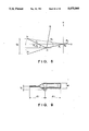
FIG. 5 is a front view of the clamp unit;
FIGS. 6A and 6B are drawings in which information with respect to the parts used in the clamp unit is summarized in a table;
FIGS. 7 to 9 are drawings of a unit model of the clamp unit shown in FIG. 4;
FIG. 10 is a flow chart which shows the control procedure for evaluating the same unit model:
FIG. 11 is an explanatory view of design conditions for creating the form of a locator;
FIG. 12 is a flow chart which shows the working procedure of the system shown in FIGS. 3A and 3B;
FIGS. 13A to 13E are flow charts which show the operating procedure of the system shown in FIGS. 3A and 3B;
FIGS. 14 and 15A to 15F are drawings of the data structure of each of the data bases used in the system shown in FIGS. 3A and 3B;
FIGS. 16A to 16D are flow charts of the processing procedure for designing the unit shown in FIG. 4;
FIG. 17 is a drawing of another example of a clamp unit; and
FIG. 18 is a drawing provided for explaining the design of the form of a bed.
DESCRIPTION OF THE PREFERRED EMBODIMENTS
An embodiment in which the present invention is applied to a CAD system for automatically designing jigs used in a car body assembly line for assembling parts to form a finished product is described below with reference to the attached drawings. The jigs are used for clamping the parts of a car in an assembly line.
PRINCIPEL OF THE EMBODIMENT
FIGS. 1 and 2 show the concept of a CAD system in this embodiment. In this CAD system, the basic data with respect to a surface on which a workpiece is worked on and the basic linkage model are used at the staring point. Although the basic data and the basic linkage model are described in detail below, the basic data include at least data with respect to a portion of a workpiece to be worked on, and the basic linkage model is a formula model (called "organization model") which expresses the mechanical relationships between the components which form the jig and which comprises a movable portion and a non.movable portion or a formula model (called "geometrical model") which expresses the geometrical relationship between the components. The geometrical model shows the configuration relationship between the respective parts and "a gap" (clearance) from the form of a workpiece and the like.
A structural model of the parts is generated from the basic data and the basic linkage model. The structural model is a set of "specifications" (the idea of "part specification") which is designed from the basic data and the basic linkage model for specifying the jig unit to be designed, and corresponds to the unit 1 to 1. When the specification of one part of the unit is determined, this specification becomes a design condition for another part. The specification determined of another part is consequently determined and becomes a design condition for a still another part. In this way, the unit structures are successively materialized in a linking manner. "A design data base" is used as a storage location for concrete data used in designing. As shown in FIG. 2, if the existing standard parts are present in the system, "the part specification" corresponds to "selection conditions" for selecting a desired part from the standard parts. If the desired part is absent from the standard parts, a specification ("creation specification") for creating a form similar to the part specification on the basis of the part specification is selected. The input and output between the respective data bases are performed through a unit structure record (FIG. 14) in the design data base.
The system for designing a jig has the following characteristics:
(1): Since "the structural model" is generated as "a set of part specification concepts" which can be easily grasped by humans, automatic design can be easily realized. In conventional CAD systems, since a design simply comprises a collection of diagrams, if an incomplete diagram is displayed in a step during the course of designing a human cannot easily grasp whether or not the incomplete diagram is appropriate.
(2): In this system for designing a jig, since the standard parts are selected in connection with the structural model formed as "a set of part specification concepts", the number of the forms of jigs which must be formed by the instructions to draw a diagram given by the operator is the minimum required value.
(3): The contact surface of a jig is formed directly on the basis of the worked on workpiece's surface data, and thus the precision of the work is significantly improved.
SUMMARY OF EMBODIMENT SYSTEM
FIGS. 3A and 3B are drawings of the whole of a CAD system in an embodiment. This CAD system is designed first for reducing the number of steps required for designing a jig, secondly for improving the precision of the NC work and thirdly for promoting standardization. For these purposes, the concept of automatic design in the system is the following:
the design prooedure and pattern are programmed,
the standard parts are programmed. on conditions and creation
the design items (selection conditions and creation conditions) are automatically calculated in accordance with the input of design conditions, p1 the standard part is retrieved and disposed in accordance with the selection conditions,
the form of a part is automatically created (output of the creation conditions),
two-dimensional diagrams are formed directly from three-dimensional data, and
NC data is generated directly from three-dimensional data.
Although the above described concept will be made clear by reading the below description, the configuration of the CAD system is described below with reference to FIGS. 3A and 3B. In the CAD system, three input databases and a single output database are used. The three input databases comprise "a work master database (WDB)" 1 containing data with respect to a workpiece to be worked on by the jig, "a standard part database (PDB)" 2 containing data with respect to the standard parts used when the jig is formed by the standard parts, and "a design standardization database (SDB)" containing the basic linkage model or the like in which the relationship between the jig components forming the jig and the mechanisms thereof or the relationship between the components and the geometry thereof are stored as a formula model. The above.described output database is "a design database" 4.
WDB 1 mainly comprises "work shape data" with respect to the form of a workpiece and "working basis data" which shows a position of the workpiece to be worked on by the jig. The three input databases which are previously formed are stored in a host system 3. When a jig is designed, the operator inputs the kind of a workpiece, a position of the workpiece to be worked on (working basis data), the selection of a linkage model and the like through a work station 8. On the assumption of these items input, the host system 3 performs detailed design in a manner of conversation with the operator. At the same time, the system 3 serves to search SDB and WDB on the basis of the basic linkage model and the working position of the workpiece, which are selected and input, as shown in FIGS. 3A and 3B, to form "a structural model" from "the basic linkage model". When the structural model is formed, incongruence such as interference between the structural model showing the jig and the workpiece is examined by using "the work shape data". If there is interference, a unique portion is designed over again so that no interference takes place. The selection conditions and the creation conditions are output on the basis of the thus-designed structural model. The standard part having a specification which agrees with the jig is searched for in the standard part database in accordance with the output selection conditions and is then output to the design database. The design part is also designed in accordance with the creation conditions and output to the design database. NC data is output from the design database together with the exploded drawing of the jig, the unit drawing, the assembly drawing and the part table and so on, as occasion demands.
JIG TO BE DESIGNED
The system shown in FIGS. 3A and 3B is capable of automatically designing various jigs for various workpiecse in correspondence with the kind of work. FIG. 4 is an exploded perspective view of an example of a jig designed by the system.
The jig is used for clamping a thin steel plate portion 16 of a workpiece and mainly comprises components such as a cylinder 10, a clamp arm 11, a locator (receiving plate) 12 ad an stand 13. Reference numeral 15 denotes the form of a basic working portion of the workpiece 16, and reference numeral 14 denotes the form of ar eceiving surface of the locator 12 which contacts with the basic working portion.l
FIG. 5 is a front view of the jig which holds the workpiece 16 in a state wherein the jig is assembled and fixed on a bed 101. The jig 100 is used for receiving the workpiece 16 and is thus called "a cradle unit" hereinafter.
In order to cause the cradle unit 100 to hold the workpiece 16 and clamp it, it is necessary to rotate the clamp arm 11 around a clamping fulcrum J1. In this jig unit 100, the rotation of the clamp arm 11 is achieved by changing the piston movement of the cylinder 10. In other words, the end of the rod 10a of the cylinder 10 is rotatably supported by the end of the clamp arm 11. The clamp arm 11 is rotatably supported by the locator 12 at the clamp fulcrum J1, and the cylinder 10 is rotatably supported at a clamp fulcrum J2. When the cylinder 10 assumes the state shown by the solid lines in FIG. 5, the clamp arm 11 clamps the workpiece 16, while when the cylinder 10 assumes the state shown by the one-dot chain lines in FIG. 5, the state of the clamp arm 10 is changed from the clamping state to a state wherein it opens, for example, at 70 degrees.
The locator 12 is fixed to the stand 13 by means of bolts, and the stand 13 is fixed to the bed 101 by means of bolts.
STANDARD PART
FIGS. 6A and 6B show the kinds of the standard parts used in the CAD system and the selection conditions and the creation conditions for specifying the standard parts. Seven kinds of standard parts are shown as examples of the standard parts. The names of the seven standard parts are "stand" model, "cylinder" model, "clamp arm" model, "locator" model, "bed" model, "cylinder bracket" model and "fitting" model.
One characteristic of the system is that "the standard parts" are seized as the concept of "the selection conditions" and "the creation conditions". Namely, for example, in the case of the part concept "cylinder" model, the concept is first specified by the part name of cylinder and then specified by "the stroke length" and "the piston diameter" of the rod of the cylinder. If "the stroke length" and "the piston diameter" are specified for the "cylinder" model, an existing cylinder is specified. The standard part database PDB is designed so that not only the dimensions of the form of the standard part specified but also non graphic specifications such as the supply maker, the weight, the name form, the price and so forth can be extracted as determination specifications. The actual graphic form displayed is generated by a cylinder graphic generating program in accordance with the stroke length specified and the piston diameter specified. In the conventional CAD system, the term "parts" represents a collection of "display graphic data" which is specified by the part names. However, in the system of the present invention, the term "parts" represents only the concept specified by "the part names" and "the selection conditions" or "the creation conditions". Namely, automatic design may be carried out on the basis of the concept of "the part names" and "the selection conditions" or "the creation conditions". If graphic display is necessary, the standard part program is called together with a functional code which requires the generation of a graphic form in accordance with the part name so that a graphic form can be generated by the program called in accordance with the creation conditions. If no graphic display is required and the part specifications such as the format name, the dimensions and the maker name are required, the functional code for outputting the specifications and the standard part program are called so that the part specifications are output.
As described above, when a part model is formed in the process of forming a structural model, the specifications of the part serve as design conditions for another part so that the unit structures are materialized in linkage with each other. The design conditions of each of the parts are listed in the item of design conditions shown in Table 6.
BASIC LINKAGE MODEL
The concept of the basic linkage model is described below. Since the greatest problem of the CAD system is to reduce the number of steps for designing, it is preferable that the number of items to be designated and input by the operator is as small as possible. The most basic data is "the function of a jig", i.e., what is the purpose of use of the jig ?. For example, the function of the jig is to clamp, as in this enbodiment. In regard to the function of clamping, in this system, forms of clamping are previously formularized and classified as described below.
(a): Classification by the direction of extension of the clamp arm with respect to the receiving surface of a workpiece.
This depends upon the direction of extension of the form of a workpiece. In the example shown in FIG. 4, since the workpiece extends toward the right side, the clamp arm extends toward the left side.
(b): Classification by the state of the cylinder rod when the action of clamping is carried out.
(c): Classification by the position of the strut of the stand with respect to a drawing as shown in FIG. 4.
(d): Classification by the form of mounting of the cylinder and the clamp arm to the locator.
For example, whether the end of the clamp arm is connected directly to the end of the cylinder rod or with a joint portion therebetween, or whether the mounting position J1 of the clamp arm to the locator is disposed above or under the mounting position J2 of the cylinder to the locator.
(e): Classificaiton by the clamping force, i.e., classification by the clamping force which is set corresponding to the working portion.
(f) Classification by the unclamping angle (70 degrees in the example shown in FIG. 5).
(g): Classification by the number of positions of a workpiece at which clamping is performed and, when clamping is performed at a plurality of positions, by the number of locators by which a plurality of cylinders and clamp arms are supported.
In he CAD system of this embodiment, a plurality of "basic linkage models" which are formularized on the basis of the above-mentioned classifications are prepared and combined for each of the forms of jigs to form a model which is displayed as a menu panel on a work station 8 so that each of the models can be selected.
The basic linkage models are expressed as formula models comprising algebraic expressions, logical discriminants, vector expressions or character expressions. In the system of this embodiment, as shown in FIGS. 6A and 6B, one of the basic linkage models is selected if the receiving surface of the workpiece and the clamping form are specified. The structural models which form one basic linkage model specified are generated, and the selection conditions and the creation conditions of the part models are determined so that the basic linkage model, which comprises only formula expressions, can be fleshed out.
The basic linkage models as formula models will be described below by using as an example the bearer unit 100 shown in FIG. 5. Each of the formula models expresses the geometrical disposal relationship between the part models which form one basic linkage model. FIG. 7 shows the geometrical model of the bearer unit 100 shown in FIG. 5. In the drawing, the symbols respectively represent the items shown in the table given below.
              TABLE                                                       
______________________________________                                    
Symbol Explanation   Note                                                 
______________________________________                                    
Θ.sub.F                                                             
       Inclination angle                                                  
                     Angle on the X - Y plane                             
       of clamping                                                        
       surface                                                            
Θ.sub.C                                                             
       Unclamping angle                                                   
                     Specified by the type of the unit                    
P.sub.0x                                                                  
       (XYZ) coordinates                                                  
                     Coordinate value corresponding                       
P.sub.0y                                                                  
       at the center of                                                   
                     to the world coordinate                              
P.sub.0z                                                                  
       clamping surface                                                   
P.sub.1x                                                                  
       (XYZ) coordinates                                                  
                     This point is positioned on the                      
P.sub.1y                                                                  
       at end point 1 of                                                  
                     cylinder side. Local coordinates                     
P.sub.1z                                                                  
       clamping surface                                                   
                     for P.sub.0                                          
P.sub.2x                                                                  
       (XYZ) coordinates                                                  
                     This point is positioned on the                      
P.sub.2y                                                                  
       at end point 2 of                                                  
                     workpiece side.                                      
P.sub.2z                                                                  
       clamping surface                                                   
                     Local coordinates for P.sub.0                        
P.sub.x                                                                   
       (XYZ) coordinates                                                  
                     Local coordinates for P.sub.0                        
P.sub.y                                                                   
       at end of clamper                                                  
P.sub.z                                                                   
       during unclamping                                                  
J.sub.1x                                                                  
       (XYZ) coordinates                                                  
                     Local coordinates for P.sub.0                        
J.sub.1y                                                                  
       at fulcrum at                                                      
J.sub.1z                                                                  
       which clamper is                                                   
       fixed                                                              
J.sub.2x                                                                  
       (XYZ) coordinates                                                  
                     Local coordinates for P.sub.0                        
J.sub.2y                                                                  
       at fixed fulcrum                                                   
J.sub.2z                                                                  
       of cylinder                                                        
J.sub.3x                                                                  
       (XYZ) coordinates                                                  
                     Local coordinates for P.sub.0                        
J.sub.3y                                                                  
       at contact point                                                   
J.sub.3z                                                                  
       of clamp rod                                                       
r.sub.1                                                                   
       Clamp arm length                                                   
                     r.sub.1 = J.sub.1 P.sub.2                            
                     = {(J.sub.1x - P.sub.2x).sup.2 + (J.sub.1y -         
                     P.sub.2y).sup.2 }1/2                                 
r.sub.2                                                                   
       Cylinder link According to the specification of                    
       length        the cylinder specified.                              
r.sub.3                                                                   
       Clamp link length                                                  
                     r.sub.3 = J.sub.1 J.sub.3                            
l.sub.1                                                                   
       Clamp rod length                                                   
       during clamping                                                    
l.sub.2                                                                   
       Clamp rod length                                                   
       during unclamping                                                  
l.sub.3                                                                   
       Cylinder length                                                    
φ.sub.c                                                               
       Outer diameter of                                                  
                     According to the specification                       
       cylinder      of the cylinder specified.                           
ΔX                                                                  
       Distance in the X                                                  
                     Design conditions                                    
       direction from P.sub.1                                             
       at end of clamper                                                  
ΔY                                                                  
       Distance in the Y                                                  
                     Design conditions                                    
       direction from P.sub.1                                             
       at end of clamper                                                  
       during unclamping                                                  
F.sub.c                                                                   
       Force exerting on                                                  
       clamping surface in                                                
       the vertical                                                       
       direction                                                          
F.sub.a                                                                   
       Cylinder output                                                    
M.sub.c                                                                   
       Moment around                                                      
       fixed fulcrum                                                      
       of clamper                                                         
φ.sub.1                                                               
       Required inner                                                     
                     Determined by clamp link length                      
       diameter of   and M.sub.c                                          
       cylinder                                                           
l.sub.L                                                                   
       Height of bed Set at the start of design of jig                    
       surface                                                            
S.sub.1                                                                   
       Required stroke of                                                 
       cylinder                                                           
______________________________________                                    
DESIGN OF UNIT
As shown in FIG. 2, one basic linkage model comprises an organization model and a geometrical model. FIG. 7 shows an organization model for designing the unit shown in FIG. 5. The organization model shown in FIG. 7 contains only a clamper and a cylinder as simple parts. This is because, since the other parts, the stand and the locator, have no movable portion, the model is configured only by the cylinder and the clamper which have movable portions. That U is, the configuration of a model is specified by using only parts having movable portions (i.e., "the selection conditions" are calculated), and non.movable portions are then determined ("the creation conditions" are calculated). On the basis of the mechanism model shown in FIG. 7, the coordinates J1 of the clamping fulcrum are first determined, and the following items are then determined:
Arm length of the clamper r1
Angle during unclamping θc
Link length of the clamper r3
Coordinates J3 at the contact point of the rod of the clamper
Stroke length of the cylinder
Internal diameter of the cylinderφ1
Fixing fulcrum of the cylinder J2
Cylinder rod length during unclamping l2
In the process for determining the above.described values, the values used at the starting point are the world coordinate values given below of the end points P1 and P2 of the surface of the workpiece 16 which is clamped and the values ΔX and ΔY at the position of the end of the clamper during unclamping.
P.sub.1 (P'.sub.1x, P'.sub.1y, P'.sub.1z)
P.sub.2 (P'.sub.2x, P'.sub.2y, P'.sub.2z)
It is important that the above.described values for determining a geometrical model are obtained from those values. For convenience of description, it is assumed that
P'.sub.1z =P'.sub.2z
The coordinates of P1, P2 are first converted into those relative to the standard point P0 so that P1 and P2 are expressed by local coordinates, as described below. ##EQU1## If the inclination angle θF of the clamping surface is determined from these coordinates, the following equation is obtained: ##EQU2## Various values are then determined from the θF value and the P1 and P2 xpressed by the local coordinates.
Coordinate Values J1 of Clamping Fulcrum
Les s be a unit vector in the direction of the line of intersection between the clamping surface and the X-axis, p be a vector from the point P2 to the point J1 and q be a vector from the point P2 to the point Q, the following equations are obtained: ##EQU3## Since the arm of the clamper makes a rotational movement, the following equations are obtained: ##EQU4## If the following definition is given: ##EQU5## and let the values of ΔX and ΔY denote condition valeus for designing the model shown in FIG. 7, the vector q is expressed by the following equation from Equation (4): ##EQU6## From Equations (2), (3) and (4), the following equation is obtained: ##EQU7## When the substitution of this equation in Equation (7) and the following change of variables are made:
α=x-P.sub.2x
β=y=P.sub.2y
the following equation is obtained: ##EQU8## Since p=k·s from Equation (2), therefore, ##EQU9## and the coordinates J1x, J1y of the clamping fulcrum are expressed by the following equation: ##EQU10## In this way, the coordinate values of the clamping fulcrum J1 are calculated. The effective range of the coordinates of the clamping fulcrum J1 is then considered.
For example, in he case of a clamp unit such as the cradle unit 101, the position of the clamping point during unclamping is limited by the distance from the end point of a workpiece and the height from the clamping surface. Namely, are provided a design condition that the position of the clamping point must be separated at an appropriate distance from the workpiece so that the workpiece can be easily attached to and removed from the jig, and a design condition that the position must not be excessively separated so that any interference with other jigs is prevented, and the work is not hindered. The end point of the workpiece can be easily obtained from the data with respect to the shape of the workpiece. However, for the convenience of description, when the point P1 is considered as the end of the shape of the workpiece, if the separation amount of the end Q of the clamper arm is ΔX and ΔY during unclamping and if the allowable range for ΔX is ΔXmin to ΔXmax, from the equation (5), when P1x <0
P.sub.1x -ΔX.sub.min ≧X≧P.sub.1x -ΔX.sub.max(10)
and when P1x >0, within the range:
P.sub.1x +ΔX.sub.min ≦X≦P.sub.1x +ΔX.sub.max(11)
J1x becomes effective. For Example, ΔXmin and ΔXmax are respectively 30 mm and 100 mm.
Arm Length r1 of Clamper
The arm length r1 of the clamper is obtained from the following equation: ##EQU11##
Unclamping Angle θc
Since the inner product ##EQU12## of the vectors ##EQU13## and s is ##EQU14## the unclamping angle θc is ##EQU15##
Link Length r3 of Clamper
If the force required for clamping the workpiece 16, which is measured in the direction vertical to the surface, is Fc (for example, 40 Kg: design constant) and if the output of the cylinder Fa, the moment Mc required rotation around the clamping fulcrum is
M.sub.c =F.sub.c ·r.sub.1
Such design conditions that the moment Mc is balanced with the moment by the cylinder and that the deflection angle of the cylinder is the minimum are shown by the following expression: ##EQU16## Therefore, the following expression is obtained: ##EQU17## On the other hand, since r3 must not be so long that the clamper interferes with other jigs or hinders the work, the following maximum value r3max is given as a design condition:
r.sub.3 ≦r.sub.3max
r3 is therefore effective within the the following range: ##EQU18##
Output Fa of Cylinder
From the formula (15), the output of the cylinder should be ##EQU19##
A decision is made as to whether or not the design conditions expressed by the equations (15) and (16) are satisfied by substituting a value, which is previously assumed, for example, the standard design value or the like, for the value of r3 or Fa, starting calculations using the ra or Fa value, repeating a series of calculations described below, and making a decision whether or not the equations (15) and (16) are established in accordance with the various values obtained from the series of calculations.
Coordinate J3 of Contact Point Between Clamper and Rod
FIG. 8 is obtained by rewriting the drawing in FIG. 7 for the purpose of causing the contact point J3 for connecting the clamper to the rod to be easily derived in a local coordinate system. As can be seen from FIG. 7, the three vectors has the relationship ##EQU20## Since ##EQU21##
Required Stroke S1 of Cylinder
Since it is found from FIG. 8 that the stroke amount
S.sub.0 =2·r.sub.3 ·sin(θ.sub.c /2),
when a margin of length ΔS (for example, 10 mm: design constant) is taken into account, the required stroke length S1 is
S.sub.1 =S.sub.0 +ΔS.
Selection of Cylinder
Under the design conditions that the cylinder has output efficiency of ηa and is operated at air pressure of P, the internal diameter φ1 of the cylinder is given as the following equation: ##EQU22## The cylinder and the bracket therefor, which satisfy the above-described required stroke S1 and the internal diameter φ1, are selected by searching the standard database for the cylinder. From the thus-selected cylinder and bracket, the cylinder link length r2, the cylinder rod length l2 during unclamping and the cylinder length 13 are determined, as shown in FIG. 9.
Coordinate J2 of Fixing Fulcrum of Cylinder
The coordinates J2 of the fulcrum for fixing the cylinder 10 to the locator are easily obtained from FIG. 7 and the coordinate position J4 of the fulcrum during unclamping.
J.sub.2x =J.sub.4x -sgn(P.sub.1x)·r.sub.2
J.sub.2y =J.sub.4y -l.sub.2
J4 is easily determined as a position of J3 which is rotated for the angle θc.
Rod Length During Unclamping
The rod length is
l.sub.1 =l.sub.2 +S.sub.0.
In this way, when a basic linkage model is selected by using the shape of the clamping surface (coordinates of P1, P2) and when the clamping force Fa and the position of the clamper arm during unclamping (clearance in unclamping) are determined, the following values are calculated:
Arm length r1 of clamper
Angle θc during unclamping
Link length r3 of clamper
Coordinates J3 of joint of clamper rod
The clamper arm can be designed by using these values. On the basis of the designed clamper arm, the values given below of the cylinder 10 which are specified in the items for the clamper arm are then selected.
Stroke length S1 of cylinder
Internal diameter φ1 of cylinder
Fixing fulcrum J2 of cylinder
Cylinder rod length l2 during unclamping
Of the movable portions, the whole of the clamper art is designed and created, while the cylinder is selected from the existing standard parts.
Inspection
Since there are cases in which the results of calculations of "the selection conditions" and "the creation conditions" are unsuitable for practical use in the above-described process of calculating them, decisions are made on these conditions.
FIG. 10 partially shows a decision program using as an example the clamper arm. In Step 2 in FIG. 10, the initial data for the creation conditions such as data for the receiving surface is set. In Step 4, the angle θ0 formed by the receiving surface and the vector q when the clamper arm is at the unclamping position is calculated. This angle is easily calculated from the definition of the inner product of the vectors s and q. ##EQU23## If the angle θc is logically over 90 degrees, the structure of the clamp unit of the present invention has no determined fulcrum and is thus not established. Thus, if θc >90°, since the selected basic linkage model is unsuitable, a next basic linkage model having a different structure is selected in Step 14.
Creation of Locator Shape
When the clamping fulcrum J1 at which the clamper arm clamps the locator and the mounting fulcrum J2 at which the cylinder is mounted on the locator are determined, the shape of the locator can be created.
Namely, the stand is determined by its type and the basic height from the bed surface, as shown in the standard part table in FIGS. 6A and 6B. When the locator is connected to the stand, it is necessary to enable the bolting at four positions at the minimum on the connection surface for the purpose of strongly connecting the locator. The width (distance between A and B in FIG. 11) of the upper portion of the locator is limited by J1 and the position of the receiving surface. The width (distance between S1 and S2 in FIG. 11) of the lower portion of the locator is limited by the width of the stand. In order to connect the locator with the stand by bolting at at least four positions, therefore, the four shape patterns shown in FIG. 11 can be logically obtained.
FIG. 11 shows the logical decision on the basis of which a shape of the mounting portion of the locator on the stand is selected from the four shape patterns by using the end points A, B on the locator side and the end points Sl, S2 on the stand side. In FIG. 11, x1, x2, X1 and X2 are defined as follows: ##EQU24## In the logical decision shown in FIG. 11, for example, if a locator having a shape having as a side the segment connecting the points B and S2 is selected in the logical decision on the first pattern, there is the possibility that bolting is unable at the position R2. In order to avoid the possibility, therefore, a locator shape in which the points B and R2 connect to each other is selected.
The above-mentioned mathematical model and the design conditions are only examples, and the contents thereof should not be limited. In other words, it is possible to add other conditions or other mathematical processing to the above embodiments.
Operation Procedure
FIG. 12 shows the working procedure of the CAD system of the present invention. FIGS. 13A to 13E show a specific operating procedure of the same system. The operating procedure is described below with reference to FIGS. 13A to 13E. In FIGS. 13A to 13E, a portion denoted by a rectangle in each of the steps shows the display screen of each of the work stations.
In Step S20, the direction and the height of the bed surface and the working basis are input. A work is displayed on the screen on the basis of the input working basis. In Step S22, the working surface is designated. In Step 26, the receiving surface is designated. In Step S28, the unclamping angle of the clamp arm which satisfies the design conditions is selected and displayed.
On the basis of these input conditions, the selection conditions an the creation conditions are calculated with reference to the above.described basic linkage model, and the processing in Steps S30 to 36 is then performed. That is, in Steps S30 and S32, search for a cylinder and an stand is made in the standard part database in accordance with the selection conditions, and the searched cylinder and stand are displayed. In Step S34, a locator is created and displayed, and in Step S36, a clamper arm is created and displayed. In Step S38, the outline of the completed cradle unit is displayed. In Step S40, the drawing of the unit is output.
Since a plurality of cradle units are necessary for one workpiece, processing in Steps S20 to S38 is repeated for each of the units. In Step 40, for convenience' sake, a case in which the positional relationship between one unit and one workpiece is shown. A description will be given of the work supposing that the work is supported by three cradle units.
In Step S42, the formation of a bed is designated. In Step S44, the basis of the shape the bed surface is input. This basis is limited by the shape of the workpiece, as shown in FIGS. 6A and 6B.
As shown in FIG. 18, stand mounting holes 45 and a cylinder hole 44 used when the cylinder interfere with the bed surface are created on the basis of the configuration data (FIG. 15D, described below) of the units on the bed surface. In Step S46, the structure of the bed surface is generated, and in Step S48, the arrangement of seats (denoted by 41 in FIG. 18) on the bed surface is displayed as shown in FIG. 18, and in Step S50, a perspective view of the whole of the bed surface is displayed. In Step S52, a drawing of a state wherein the units are mounted on the bed is displayed.
In FIG. 18, reference numeral 40 denotes an upper plate; reference numeral 42, a peripheral channel structure; and reference numeral 43, an internal structure (flat bar). The stand mounting holes 45 comprise stand mounting basic knock holes and bolt holes. The mounting holes 45 and the escape hole 44 are generated by using the configuration data for the clamp units on the bed surface and the structural models of the units.
In this way, when the design is finished, the drawing and NC data ar formed.
Data Structure in System
FIG. 14 is a drawing of a relationship between the respective databases in this CAD system. FIGS. 15A to 15F show in detail the flow of the data shown in FIG. 14. FIG. 15A shows the work master database (WDB). FIGS. 16A to 16D show the outline of the processing in the system for designing jig units.
The outline of the data structure is described below with reference to FIGS. 14 to 16.
When the formation of a unit is designated from the work station (Step S100 in FIG. 16A), a status record (FIG. 15B) for managing the progress state of automatic design, e.g., the number of units so far formed, is formed, as well as the working basis (working position) being set in the work station (Step S104). The position codes K are selected from the WDB (refer to FIG. 15A) on the basis of the working basis. The position codes are indexes which indicate a plurality of working positions in each workpiece. From the WDB are output the position codes K directed to a design standardization database SDB (FIG. 15C), the status recor (FIG. 15B) and the unit arrangement data and the shape data of the works and the working positions which are directed to the unit structure record (FIG. 15D). The unit arrangement data is data with respect to the positions at which the jig units formed are disposed on the bed.
The position codes K are used for indexing the unit structure record, a standard design procedure and a set of design evaluation functions, as shown in FIG. 15C. The standard design procedure is unique for the type of each jig, for example, in the case of the unit shown in FIG. 4, the standard procedure is a program containing the procedure comprising the steps of first designing a cylinder and an stand which are selected parts, and then designing a locator and a clamp arm, which are parts having created forms, on the basis of the selected parts so that basic linkage models are generated and expressed in accordance with the procedure. The evaluation function set comprises, for example, the mathematical models which respectively correspond to the basic linkage models and which are described above with reference to FIGS. 7 to 11.
The structural design evaluation program for a jig is started in accordance with the selected procedure and evaluation function set. The unit structure record is also generated and initialized. The above.described structure model generated by using the unit arrangement data, the workpiece shape and working position shape data and the part design conditions are stored in the unit structure record.
The structural design evaluation program started outputs the selection conditions to the part selection program and the creation conditions to the part shape creation program. The part selection program and the part shape creation program output as request specifications the selection conditions and the creation conditions to the standard part database RDB (FIG. 15E) and input as decision specifications. The programs return the decision specifications to the structural design evaluation program used for evaluation.
The decided part specifications are stored as three-dimensional data in the jig design database (DDB) by the shape creating program.
As shown in FIG. 15F, the drawing formation program, NC data generation program, the three dimensional data stored in DDB and various output programs generate and output two-dimensional drawings and the NC working data.
The parallel processing procedure from the generation of the structural models (Step S108) to the generation of each part is described below with reference to FIGS. 16A to 16D. The meanings of the symbols shown in the drawings are shown in FIG. 16E. In the drawings, symbol (a) represents processing operated by the evaluation function corresponding to each of the unit types; symbol (b), the data values stored in the boundary condition record in the unit structure record; symbol (c), the jig design database DDB; and symbol (d), the standard part database PDB.
When the clamping fulcrum J1, the link length r2, the stroke length S2 of the cylinder, the cylinder output Fa and the unclamping angle θc are determined in Step S110, the specifications of the cylinder are determined in Step S112 and the rod length, type number and so on are input as decision specifications from the standard part database PDB. In Step S116, the cylinder mounting position J2 is calculated from the decision specifications, and in Step S120, the shape of the cylinder is generated and disposed, as well as the data with respect to the cylinder being used for selecting the stand in Step S160.
In Step S130, the shape of the clamper is created on the basis of the clamping fulcrum coordinates J1 calculated in Step S1l0 and the working basis data.
In Step S160, the basic height of the stand is set for selecting an stand on the basis of the basic working position and the sectional shape of the workpiece and the cylinder mounting position J2 obtained in Step S118. In Step S164, the stand is selected from the standard part database.
In Step S140, the shape of the locator is created. In Step S140, the shape of the receiving surface (clamping surface shape) of the locator is created on the basis of the working basis. The creation of the shape of the receiving surface on the basis of the working basis (receiving surface shape of the workpiece) contributes to an improvement in the working precision of a jig, as described above. In Step S144, the clamp arm mounting position J1, the cylinder mounting position J2 and the bolt mounting positions for the stand in the locator are input so that the shape of the locator is generated. This is described above with reference to FIG. 11.
FIG. 17 is a front view of a clamp unit in which two cylinders and clamper arms are mounted on one locator. Although a basic linkage model for such a unit is different from that shown in FIG. 7, it is basically the same as that.
Effect of the Embodiment
The above-mentioned embodiment has the following effects:
(1) The structural models of parts which form a jig can be successively designed in linkage with each other on the assumption of the most basic design starting conditions for working positions of a workpiece which are contained in working basis data and basic linkage models which roughly show the components of the jig. Automatic design can be performed by simple operations with a high level of efficiency.
Since the basic mechanical structures of the components are contained in the basic linkage models, the designer may select only the design conditions, which are shown as a selection branch, in the process of design. The operator can also design a jig with a high level of design efficiency because the complicated calculations for calculating the design conditions are performed by the system.
(2): The best way is to select parts of a jig from the existing parts. However, it is not always impossible to select all the parts from the existing parts. Jigs used for the same purpose inevitably have different forms in correspondence with the conditions for use of the units. When a part is not present in the existing parts, therefore, the part must be created.
In this embodiment, the basic linkage models contain information with respect to the discrimination between the parts selected (the cylinder, the stand and the like) and the parts created (the clamp arm, the locator, the bed and the like) in the parts forming a jig. The structural models contain as output the selection conditions comprising the part specifications to which the existing parts conform and the creation conditions comprising the part specifications which must be satisfied by the parts having shapes to be newly created. Existing standard parts are selected from the selection conditions, and part shapes which the most agree with the selected parts in mechanical linkage therewith are created from the creation conditions.
In other words, the selection conditions and the creation conditions output as the structural models are a collection of part specifications. If various items of information such as correct information for part shapes, type numbers and makers of parts and so on are stored in the standard part database, therefore, it is possible to obtain all required information by searching the standard part database using as indexes the part specifications. For example, part tables can be easily output. (3): The above.described embodiment has as basic working data the shapes of the portions where the clamper cradle unit contacts directly with the workpiece. The shape of the surface of contact between the workpiece and the clamper arm of cradle unit is suitable for contact, resulting in the design of a jig with a high level of precision.
The present invention can be modified into various forms within the range of the gist of the invention, and thus the scope of the present invention includes modification, improvement, equivalents and so on. The present invention should be interpreted by the attached claims.

Claims (8)

What is claimed is:
1. An automatic jig design apparatus for automatically designing a jig comprising at least oen part, said apparatus comprising:
linkage model generating means for generating a basic linkage model which basically shows the linkage between said at least one part;
input means for inputting data concerning a working position of a workpiece to be worked on by said jig; and
structural model generating means for starting with the inputted data via the input means and successively generating structural models of said at least one part formign said jig in accordance with said basic linkage model.
2. An apparatus according ot claim 1, further comprising:
storage means for previously storing a plurality of basic linkage models;
setting means for setting allowable conditions for design of a jig;
comparison means for comaring a structural model of a part generated by said structural model generating means with said allowabel conditions;
retrieving means for retrieving other basic linkage models from said storage means on the basis of the results of comparison.
3. An apparatus according to claim 1, wherein the type of working by said jig is clamping, and said working position of said workpiece to be worked on is a contact surface clamped by said jig.
4. An apparatus according to claim 1, wherein said jig comprises movable components and non-movable components, said structural model generating means being started for designing said movable components.
5. An apparatus according to claim 1, wherein said linkage model generating means serves to store data with respect to said working position of said workpiece to be worked on by said jig in a database for each workpiece.
6. An apparatus according to claim 1, wherein said basic linkage model is prepared for each type of jig and workpiece.
7. An apparatus according to claim 1, wherein said structural model generating means further comprises:
data base means for storing a database of standard parts one of which can be selected as said at least one part; and
means for searchign for a standard part in the data base means in accordance with the basic linkage model.
8. A method of automatically designing a jig comprising at least one part, said method comprising steps of:
specifying a type of jig and a type of workpiece to be worked on thereby;
searching for a basic linkage model which basically shows a linkage between said at least one part of the jig specified by using as keys said type of said jig and said type of said workpiece; and
successively generating structural models of said at least one part forming said jig by using data with respect to a working position of said workpiece to be worked on by said jig in accordance with said basic linkage model searched for.
US07/426,875 1988-10-26 1989-10-25 Apparatus for automatically designing jig Expired - Fee Related US5075866A (en)

Applications Claiming Priority (2)

Application Number Priority Date Filing Date Title
JP63-268327 1988-10-26
JP63268327A JP2779181B2 (en) 1988-10-26 1988-10-26 Jig automatic design apparatus and jig design method

Publications (1)

Publication Number Publication Date
US5075866A true US5075866A (en) 1991-12-24

Family

ID=17457004

Family Applications (1)

Application Number Title Priority Date Filing Date
US07/426,875 Expired - Fee Related US5075866A (en) 1988-10-26 1989-10-25 Apparatus for automatically designing jig

Country Status (5)

Country Link
US (1) US5075866A (en)
EP (1) EP0366069B1 (en)
JP (1) JP2779181B2 (en)
KR (1) KR930003128B1 (en)
DE (1) DE68928526T2 (en)

Cited By (32)

* Cited by examiner, † Cited by third party
Publication number Priority date Publication date Assignee Title
US5211061A (en) * 1991-07-16 1993-05-18 Goodwin Jerry J Bolt clamping force sensor and clamping force validation method
US5278479A (en) * 1990-08-09 1994-01-11 Fanuc Ltd. Tool path drawing method
US5311784A (en) * 1990-11-21 1994-05-17 Societe Hispano-Suiza Dimensional quality control method for cast parts
US5941143A (en) * 1995-11-16 1999-08-24 University Of Kentucky Research Foundation Method of assessing chip breakability performance
US20020133265A1 (en) * 2001-03-14 2002-09-19 Landers Diane M. Horizontally structured manufacturing process modeling for concurrent product and process design
US20020133267A1 (en) * 2001-03-14 2002-09-19 Landers Diane M. Enhancement to horizontally structured manufacturing process modeling
US20040015254A1 (en) * 2000-08-09 2004-01-22 Vancraen Wilfried Frans Isidoor Method for manufacturing a supporting and/or reference construction
US6901356B1 (en) * 1998-03-20 2005-05-31 Fujitsu Limited Simulation apparatus, simulation method and computer-readable recording medium having simulation program recorded thereon as well as designing supporting apparatus
US20100033560A1 (en) * 2008-08-06 2010-02-11 Hitachi High-Technologies Corporation Method and Apparatus of Tilted Illumination Observation
USD642263S1 (en) 2007-10-25 2011-07-26 Otismed Corporation Arthroplasty jig blank
US8160345B2 (en) 2008-04-30 2012-04-17 Otismed Corporation System and method for image segmentation in generating computer models of a joint to undergo arthroplasty
US8221430B2 (en) 2007-12-18 2012-07-17 Otismed Corporation System and method for manufacturing arthroplasty jigs
US8311306B2 (en) 2008-04-30 2012-11-13 Otismed Corporation System and method for image segmentation in generating computer models of a joint to undergo arthroplasty
US8460303B2 (en) 2007-10-25 2013-06-11 Otismed Corporation Arthroplasty systems and devices, and related methods
US8460302B2 (en) 2006-12-18 2013-06-11 Otismed Corporation Arthroplasty devices and related methods
US8480679B2 (en) 2008-04-29 2013-07-09 Otismed Corporation Generation of a computerized bone model representative of a pre-degenerated state and useable in the design and manufacture of arthroplasty devices
WO2013104741A1 (en) * 2012-01-13 2013-07-18 Materialise N.V. Locator for supporting and/or positioning an object
US8545509B2 (en) 2007-12-18 2013-10-01 Otismed Corporation Arthroplasty system and related methods
US8617175B2 (en) 2008-12-16 2013-12-31 Otismed Corporation Unicompartmental customized arthroplasty cutting jigs and methods of making the same
US8617171B2 (en) 2007-12-18 2013-12-31 Otismed Corporation Preoperatively planning an arthroplasty procedure and generating a corresponding patient specific arthroplasty resection guide
US8715291B2 (en) 2007-12-18 2014-05-06 Otismed Corporation Arthroplasty system and related methods
US8737700B2 (en) 2007-12-18 2014-05-27 Otismed Corporation Preoperatively planning an arthroplasty procedure and generating a corresponding patient specific arthroplasty resection guide
US8734455B2 (en) 2008-02-29 2014-05-27 Otismed Corporation Hip resurfacing surgical guide tool
US8777875B2 (en) 2008-07-23 2014-07-15 Otismed Corporation System and method for manufacturing arthroplasty jigs having improved mating accuracy
US8801720B2 (en) 2002-05-15 2014-08-12 Otismed Corporation Total joint arthroplasty system
US9017336B2 (en) 2006-02-15 2015-04-28 Otismed Corporation Arthroplasty devices and related methods
US9402637B2 (en) 2012-10-11 2016-08-02 Howmedica Osteonics Corporation Customized arthroplasty cutting guides and surgical methods using the same
US20170001374A1 (en) * 2015-07-01 2017-01-05 General Electric Company Method for additively manufacturing component and component made therefrom
US9808262B2 (en) 2006-02-15 2017-11-07 Howmedica Osteonics Corporation Arthroplasty devices and related methods
US20180260496A1 (en) * 2017-03-09 2018-09-13 Fanuc Corporation Jig design assisting device and robot simulation device
US10386813B2 (en) * 2015-12-04 2019-08-20 Fanuc Corporation Combined system having machine tool and robot
US10582934B2 (en) 2007-11-27 2020-03-10 Howmedica Osteonics Corporation Generating MRI images usable for the creation of 3D bone models employed to make customized arthroplasty jigs

Families Citing this family (7)

* Cited by examiner, † Cited by third party
Publication number Priority date Publication date Assignee Title
US5278953A (en) * 1991-11-08 1994-01-11 Aura Systems, Inc. Machine tool fixture computer aided setup
IT1250369B (en) * 1991-12-23 1995-04-07 Fiat Auto Spa MOLD MODEL FOR THE MEASUREMENT OF PARAMETER VALUES INHERENT TO THE DRAWING OF SHEET METAL SHEETS AND PROCEDURE USING IT.
US6088625A (en) 1996-08-23 2000-07-11 Kellstrom, Jr.; Gary E. System for transferring assembly data and method therefor
EP1881384A1 (en) * 2006-07-21 2008-01-23 Dassault Systèmes Computer implemented method for defining an input product
WO2011139071A2 (en) * 2010-05-04 2011-11-10 주식회사 유디엠텍 3d jig modeling device and method thereof
US20120112397A1 (en) * 2010-11-05 2012-05-10 Delaware Capital Formation, Inc. Linkage Clamp
CA2964720C (en) * 2014-10-15 2019-03-19 Honda Motor Co., Ltd. Jig information setting method and jig information setting device

Citations (11)

* Cited by examiner, † Cited by third party
Publication number Priority date Publication date Assignee Title
US4530046A (en) * 1982-03-23 1985-07-16 Toyoda Koki Kabushiki Kaisha Method of inputting machining information to a machine tool numerical controller and apparatus therefor
US4547854A (en) * 1981-11-05 1985-10-15 Yamazaki Machinery Works, Ltd. Method of controlling lineup of tools in numerical control machine tool
US4549270A (en) * 1982-03-11 1985-10-22 Yamazaki Machinery Works, Ltd. Method of controlling selection of tools in a quadriaxial numerical control lathe
US4618924A (en) * 1984-09-28 1986-10-21 General Electric Company Automatic machining using constructive solid geometry with Boolean combinations of primitives including tool offsets to form a machining pattern
US4641270A (en) * 1984-04-25 1987-02-03 La Telemecanique Electrique Process for manufacturing a mold using three-dimensional computer modelling
US4656590A (en) * 1984-11-07 1987-04-07 Ronald Ace Method and apparatus for making patterns for eyeglasses
JPS62137129A (en) * 1985-12-09 1987-06-20 Chiyuushiyou Kigyo Jigyodan Assisting system for designing metal die by computer
US4739488A (en) * 1984-09-21 1988-04-19 Brother Kogyo Kabushiki Kaisha Machine tool with tool selection and work sequence determination
US4918627A (en) * 1986-08-04 1990-04-17 Fmc Corporation Computer integrated gaging system
US4937768A (en) * 1987-04-14 1990-06-26 Northrop Corporation Integrated assembly system
US4936862A (en) * 1986-05-30 1990-06-26 Walker Peter S Method of designing and manufacturing a human joint prosthesis

Patent Citations (11)

* Cited by examiner, † Cited by third party
Publication number Priority date Publication date Assignee Title
US4547854A (en) * 1981-11-05 1985-10-15 Yamazaki Machinery Works, Ltd. Method of controlling lineup of tools in numerical control machine tool
US4549270A (en) * 1982-03-11 1985-10-22 Yamazaki Machinery Works, Ltd. Method of controlling selection of tools in a quadriaxial numerical control lathe
US4530046A (en) * 1982-03-23 1985-07-16 Toyoda Koki Kabushiki Kaisha Method of inputting machining information to a machine tool numerical controller and apparatus therefor
US4641270A (en) * 1984-04-25 1987-02-03 La Telemecanique Electrique Process for manufacturing a mold using three-dimensional computer modelling
US4739488A (en) * 1984-09-21 1988-04-19 Brother Kogyo Kabushiki Kaisha Machine tool with tool selection and work sequence determination
US4618924A (en) * 1984-09-28 1986-10-21 General Electric Company Automatic machining using constructive solid geometry with Boolean combinations of primitives including tool offsets to form a machining pattern
US4656590A (en) * 1984-11-07 1987-04-07 Ronald Ace Method and apparatus for making patterns for eyeglasses
JPS62137129A (en) * 1985-12-09 1987-06-20 Chiyuushiyou Kigyo Jigyodan Assisting system for designing metal die by computer
US4936862A (en) * 1986-05-30 1990-06-26 Walker Peter S Method of designing and manufacturing a human joint prosthesis
US4918627A (en) * 1986-08-04 1990-04-17 Fmc Corporation Computer integrated gaging system
US4937768A (en) * 1987-04-14 1990-06-26 Northrop Corporation Integrated assembly system

Non-Patent Citations (2)

* Cited by examiner, † Cited by third party
Title
Article, Journal of Manufacturing Systems , vol. 7, No. 2 entitled Principles for Part Setup and Workholding in Automated Manufacturing . *
Article, Journal of Manufacturing Systems, vol. 7, No. 2 entitled "Principles for Part Setup and Workholding in Automated Manufacturing".

Cited By (44)

* Cited by examiner, † Cited by third party
Publication number Priority date Publication date Assignee Title
US5278479A (en) * 1990-08-09 1994-01-11 Fanuc Ltd. Tool path drawing method
US5311784A (en) * 1990-11-21 1994-05-17 Societe Hispano-Suiza Dimensional quality control method for cast parts
US5211061A (en) * 1991-07-16 1993-05-18 Goodwin Jerry J Bolt clamping force sensor and clamping force validation method
US5941143A (en) * 1995-11-16 1999-08-24 University Of Kentucky Research Foundation Method of assessing chip breakability performance
US6901356B1 (en) * 1998-03-20 2005-05-31 Fujitsu Limited Simulation apparatus, simulation method and computer-readable recording medium having simulation program recorded thereon as well as designing supporting apparatus
US20040015254A1 (en) * 2000-08-09 2004-01-22 Vancraen Wilfried Frans Isidoor Method for manufacturing a supporting and/or reference construction
US20020133265A1 (en) * 2001-03-14 2002-09-19 Landers Diane M. Horizontally structured manufacturing process modeling for concurrent product and process design
US20020133267A1 (en) * 2001-03-14 2002-09-19 Landers Diane M. Enhancement to horizontally structured manufacturing process modeling
US8801719B2 (en) 2002-05-15 2014-08-12 Otismed Corporation Total joint arthroplasty system
US8801720B2 (en) 2002-05-15 2014-08-12 Otismed Corporation Total joint arthroplasty system
US9808262B2 (en) 2006-02-15 2017-11-07 Howmedica Osteonics Corporation Arthroplasty devices and related methods
US9017336B2 (en) 2006-02-15 2015-04-28 Otismed Corporation Arthroplasty devices and related methods
US8460302B2 (en) 2006-12-18 2013-06-11 Otismed Corporation Arthroplasty devices and related methods
USD642263S1 (en) 2007-10-25 2011-07-26 Otismed Corporation Arthroplasty jig blank
USD691719S1 (en) 2007-10-25 2013-10-15 Otismed Corporation Arthroplasty jig blank
US8460303B2 (en) 2007-10-25 2013-06-11 Otismed Corporation Arthroplasty systems and devices, and related methods
US10582934B2 (en) 2007-11-27 2020-03-10 Howmedica Osteonics Corporation Generating MRI images usable for the creation of 3D bone models employed to make customized arthroplasty jigs
US8617171B2 (en) 2007-12-18 2013-12-31 Otismed Corporation Preoperatively planning an arthroplasty procedure and generating a corresponding patient specific arthroplasty resection guide
US8221430B2 (en) 2007-12-18 2012-07-17 Otismed Corporation System and method for manufacturing arthroplasty jigs
US8545509B2 (en) 2007-12-18 2013-10-01 Otismed Corporation Arthroplasty system and related methods
US9649170B2 (en) 2007-12-18 2017-05-16 Howmedica Osteonics Corporation Arthroplasty system and related methods
US8968320B2 (en) 2007-12-18 2015-03-03 Otismed Corporation System and method for manufacturing arthroplasty jigs
US8737700B2 (en) 2007-12-18 2014-05-27 Otismed Corporation Preoperatively planning an arthroplasty procedure and generating a corresponding patient specific arthroplasty resection guide
US8715291B2 (en) 2007-12-18 2014-05-06 Otismed Corporation Arthroplasty system and related methods
US9408618B2 (en) 2008-02-29 2016-08-09 Howmedica Osteonics Corporation Total hip replacement surgical guide tool
US8734455B2 (en) 2008-02-29 2014-05-27 Otismed Corporation Hip resurfacing surgical guide tool
US9646113B2 (en) 2008-04-29 2017-05-09 Howmedica Osteonics Corporation Generation of a computerized bone model representative of a pre-degenerated state and useable in the design and manufacture of arthroplasty devices
US8480679B2 (en) 2008-04-29 2013-07-09 Otismed Corporation Generation of a computerized bone model representative of a pre-degenerated state and useable in the design and manufacture of arthroplasty devices
US8483469B2 (en) 2008-04-30 2013-07-09 Otismed Corporation System and method for image segmentation in generating computer models of a joint to undergo arthroplasty
US8532361B2 (en) 2008-04-30 2013-09-10 Otismed Corporation System and method for image segmentation in generating computer models of a joint to undergo arthroplasty
US9208263B2 (en) 2008-04-30 2015-12-08 Howmedica Osteonics Corporation System and method for image segmentation in generating computer models of a joint to undergo arthroplasty
US8311306B2 (en) 2008-04-30 2012-11-13 Otismed Corporation System and method for image segmentation in generating computer models of a joint to undergo arthroplasty
US8160345B2 (en) 2008-04-30 2012-04-17 Otismed Corporation System and method for image segmentation in generating computer models of a joint to undergo arthroplasty
US8777875B2 (en) 2008-07-23 2014-07-15 Otismed Corporation System and method for manufacturing arthroplasty jigs having improved mating accuracy
US20100033560A1 (en) * 2008-08-06 2010-02-11 Hitachi High-Technologies Corporation Method and Apparatus of Tilted Illumination Observation
US8617175B2 (en) 2008-12-16 2013-12-31 Otismed Corporation Unicompartmental customized arthroplasty cutting jigs and methods of making the same
WO2013104741A1 (en) * 2012-01-13 2013-07-18 Materialise N.V. Locator for supporting and/or positioning an object
US9402637B2 (en) 2012-10-11 2016-08-02 Howmedica Osteonics Corporation Customized arthroplasty cutting guides and surgical methods using the same
US20170001374A1 (en) * 2015-07-01 2017-01-05 General Electric Company Method for additively manufacturing component and component made therefrom
US10086567B2 (en) * 2015-07-01 2018-10-02 General Electric Company Method for additively manufacturing component and component made therefrom
US20190016053A1 (en) * 2015-07-01 2019-01-17 General Electric Company Method for additively manufacturing component and component made therefrom
US10532515B2 (en) * 2015-07-01 2020-01-14 General Electric Company Additively manufactured component with locator element for aligning sub-components
US10386813B2 (en) * 2015-12-04 2019-08-20 Fanuc Corporation Combined system having machine tool and robot
US20180260496A1 (en) * 2017-03-09 2018-09-13 Fanuc Corporation Jig design assisting device and robot simulation device

Also Published As

Publication number Publication date
JPH02115980A (en) 1990-04-27
EP0366069A2 (en) 1990-05-02
DE68928526T2 (en) 1998-08-06
EP0366069B1 (en) 1998-01-07
EP0366069A3 (en) 1991-09-11
KR930003128B1 (en) 1993-04-19
JP2779181B2 (en) 1998-07-23
KR900006880A (en) 1990-05-09
DE68928526D1 (en) 1998-02-12

Similar Documents

Publication Publication Date Title
US5075866A (en) Apparatus for automatically designing jig
US5822207A (en) Apparatus and method for integrating intelligent manufacturing system with expert sheet metal planning and bending system
US5388199A (en) Interactive graphic input system
KR100645129B1 (en) Automatic programming method and automatic programming device
US6611786B1 (en) Apparatus and method concerning analysis and generation of part program for measuring coordinates and surface properties
US20030114945A1 (en) Apparatus and method for creating intermediate stage model
Rembold et al. Computer-aided design and manufacturing: methods and tools
US6224249B1 (en) Compound design system and method for mechanism parts
US5369870A (en) Method for deciding procedure of machining
EP0499905B1 (en) CAD/CAM unit data generating apparatus and process
JPH10149432A (en) Three-dimensional form retrieval device
JP2586889B2 (en) Interactive graphic input system
JP2940923B2 (en) Jig automatic design apparatus and jig design method
JP2779180B2 (en) Jig automatic design apparatus and jig design method
US5737218A (en) System with graphical interface for modifying position of programmable fixture devices
JP2800592B2 (en) Tool placement interference check method for machined figure data
Ehrismann et al. Intelligent manufacture of laser cutting, punching and bending parts
JP3886164B2 (en) Method and apparatus for creating tool cutting path for NC machining
JP2647650B2 (en) Generation method of machining information of free-form surface without tool interference
US6681144B1 (en) Process and system for working a workpiece through numerically controlled machine tools
JP3157893B2 (en) Method and program for automatically creating machining path statement of NC program for laser machining
CN112926158B (en) General design method based on parameter fine adjustment in industrial machinery design scene
JPH07182019A (en) Working information generator
JPH0767659B2 (en) Free curved surface machining information generation system considering finish surface roughness
Chou Automated planning and design of fixtures for complex parts

Legal Events

Date Code Title Description
AS Assignment

Owner name: MAZDA MOTOR CORPORATION, A CORP. OF JAPAN, JAPAN

Free format text: ASSIGNMENT OF ASSIGNORS INTEREST.;ASSIGNORS:GOTO, SUNAO;KAWANO, MASARU;REEL/FRAME:005221/0824

Effective date: 19840926

CC Certificate of correction
FEPP Fee payment procedure

Free format text: PAYOR NUMBER ASSIGNED (ORIGINAL EVENT CODE: ASPN); ENTITY STATUS OF PATENT OWNER: LARGE ENTITY

FPAY Fee payment

Year of fee payment: 4

FPAY Fee payment

Year of fee payment: 8

REMI Maintenance fee reminder mailed
LAPS Lapse for failure to pay maintenance fees
STCH Information on status: patent discontinuation

Free format text: PATENT EXPIRED DUE TO NONPAYMENT OF MAINTENANCE FEES UNDER 37 CFR 1.362

FP Lapsed due to failure to pay maintenance fee

Effective date: 20031224