US5020516A - Circulatory assist method and apparatus - Google Patents
Circulatory assist method and apparatus Download PDFInfo
- Publication number
- US5020516A US5020516A US07/175,810 US17581088A US5020516A US 5020516 A US5020516 A US 5020516A US 17581088 A US17581088 A US 17581088A US 5020516 A US5020516 A US 5020516A
- Authority
- US
- United States
- Prior art keywords
- patient
- oxygen
- output
- cardiac output
- cardiac
- Prior art date
- Legal status (The legal status is an assumption and is not a legal conclusion. Google has not performed a legal analysis and makes no representation as to the accuracy of the status listed.)
- Expired - Lifetime
Links
Images


Classifications
-
- A—HUMAN NECESSITIES
- A61—MEDICAL OR VETERINARY SCIENCE; HYGIENE
- A61H—PHYSICAL THERAPY APPARATUS, e.g. DEVICES FOR LOCATING OR STIMULATING REFLEX POINTS IN THE BODY; ARTIFICIAL RESPIRATION; MASSAGE; BATHING DEVICES FOR SPECIAL THERAPEUTIC OR HYGIENIC PURPOSES OR SPECIFIC PARTS OF THE BODY
- A61H31/00—Artificial respiration or heart stimulation, e.g. heart massage
- A61H31/004—Heart stimulation
- A61H31/005—Heart stimulation with feedback for the user
-
- A—HUMAN NECESSITIES
- A61—MEDICAL OR VETERINARY SCIENCE; HYGIENE
- A61H—PHYSICAL THERAPY APPARATUS, e.g. DEVICES FOR LOCATING OR STIMULATING REFLEX POINTS IN THE BODY; ARTIFICIAL RESPIRATION; MASSAGE; BATHING DEVICES FOR SPECIAL THERAPEUTIC OR HYGIENIC PURPOSES OR SPECIFIC PARTS OF THE BODY
- A61H31/00—Artificial respiration or heart stimulation, e.g. heart massage
- A61H31/004—Heart stimulation
- A61H31/006—Power driven
-
- A—HUMAN NECESSITIES
- A61—MEDICAL OR VETERINARY SCIENCE; HYGIENE
- A61H—PHYSICAL THERAPY APPARATUS, e.g. DEVICES FOR LOCATING OR STIMULATING REFLEX POINTS IN THE BODY; ARTIFICIAL RESPIRATION; MASSAGE; BATHING DEVICES FOR SPECIAL THERAPEUTIC OR HYGIENIC PURPOSES OR SPECIFIC PARTS OF THE BODY
- A61H9/00—Pneumatic or hydraulic massage
- A61H9/005—Pneumatic massage
- A61H9/0078—Pneumatic massage with intermittent or alternately inflated bladders or cuffs
-
- A—HUMAN NECESSITIES
- A61—MEDICAL OR VETERINARY SCIENCE; HYGIENE
- A61M—DEVICES FOR INTRODUCING MEDIA INTO, OR ONTO, THE BODY; DEVICES FOR TRANSDUCING BODY MEDIA OR FOR TAKING MEDIA FROM THE BODY; DEVICES FOR PRODUCING OR ENDING SLEEP OR STUPOR
- A61M60/00—Blood pumps; Devices for mechanical circulatory actuation; Balloon pumps for circulatory assistance
- A61M60/10—Location thereof with respect to the patient's body
- A61M60/122—Implantable pumps or pumping devices, i.e. the blood being pumped inside the patient's body
- A61M60/165—Implantable pumps or pumping devices, i.e. the blood being pumped inside the patient's body implantable in, on, or around the heart
-
- A—HUMAN NECESSITIES
- A61—MEDICAL OR VETERINARY SCIENCE; HYGIENE
- A61M—DEVICES FOR INTRODUCING MEDIA INTO, OR ONTO, THE BODY; DEVICES FOR TRANSDUCING BODY MEDIA OR FOR TAKING MEDIA FROM THE BODY; DEVICES FOR PRODUCING OR ENDING SLEEP OR STUPOR
- A61M60/00—Blood pumps; Devices for mechanical circulatory actuation; Balloon pumps for circulatory assistance
- A61M60/30—Medical purposes thereof other than the enhancement of the cardiac output
- A61M60/36—Medical purposes thereof other than the enhancement of the cardiac output for specific blood treatment; for specific therapy
- A61M60/38—Blood oxygenation
-
- A—HUMAN NECESSITIES
- A61—MEDICAL OR VETERINARY SCIENCE; HYGIENE
- A61M—DEVICES FOR INTRODUCING MEDIA INTO, OR ONTO, THE BODY; DEVICES FOR TRANSDUCING BODY MEDIA OR FOR TAKING MEDIA FROM THE BODY; DEVICES FOR PRODUCING OR ENDING SLEEP OR STUPOR
- A61M60/00—Blood pumps; Devices for mechanical circulatory actuation; Balloon pumps for circulatory assistance
- A61M60/50—Details relating to control
- A61M60/508—Electronic control means, e.g. for feedback regulation
- A61M60/515—Regulation using real-time patient data
- A61M60/523—Regulation using real-time patient data using blood flow data, e.g. from blood flow transducers
-
- A—HUMAN NECESSITIES
- A61—MEDICAL OR VETERINARY SCIENCE; HYGIENE
- A61M—DEVICES FOR INTRODUCING MEDIA INTO, OR ONTO, THE BODY; DEVICES FOR TRANSDUCING BODY MEDIA OR FOR TAKING MEDIA FROM THE BODY; DEVICES FOR PRODUCING OR ENDING SLEEP OR STUPOR
- A61M60/00—Blood pumps; Devices for mechanical circulatory actuation; Balloon pumps for circulatory assistance
- A61M60/50—Details relating to control
- A61M60/508—Electronic control means, e.g. for feedback regulation
- A61M60/562—Electronic control means, e.g. for feedback regulation for making blood flow pulsatile in blood pumps that do not intrinsically create pulsatile flow
- A61M60/569—Electronic control means, e.g. for feedback regulation for making blood flow pulsatile in blood pumps that do not intrinsically create pulsatile flow synchronous with the native heart beat
-
- A—HUMAN NECESSITIES
- A61—MEDICAL OR VETERINARY SCIENCE; HYGIENE
- A61M—DEVICES FOR INTRODUCING MEDIA INTO, OR ONTO, THE BODY; DEVICES FOR TRANSDUCING BODY MEDIA OR FOR TAKING MEDIA FROM THE BODY; DEVICES FOR PRODUCING OR ENDING SLEEP OR STUPOR
- A61M60/00—Blood pumps; Devices for mechanical circulatory actuation; Balloon pumps for circulatory assistance
- A61M60/50—Details relating to control
- A61M60/592—Communication of patient or blood pump data to distant operators for treatment purposes
-
- A—HUMAN NECESSITIES
- A61—MEDICAL OR VETERINARY SCIENCE; HYGIENE
- A61H—PHYSICAL THERAPY APPARATUS, e.g. DEVICES FOR LOCATING OR STIMULATING REFLEX POINTS IN THE BODY; ARTIFICIAL RESPIRATION; MASSAGE; BATHING DEVICES FOR SPECIAL THERAPEUTIC OR HYGIENIC PURPOSES OR SPECIFIC PARTS OF THE BODY
- A61H2201/00—Characteristics of apparatus not provided for in the preceding codes
- A61H2201/01—Constructive details
- A61H2201/0103—Constructive details inflatable
-
- A—HUMAN NECESSITIES
- A61—MEDICAL OR VETERINARY SCIENCE; HYGIENE
- A61H—PHYSICAL THERAPY APPARATUS, e.g. DEVICES FOR LOCATING OR STIMULATING REFLEX POINTS IN THE BODY; ARTIFICIAL RESPIRATION; MASSAGE; BATHING DEVICES FOR SPECIAL THERAPEUTIC OR HYGIENIC PURPOSES OR SPECIFIC PARTS OF THE BODY
- A61H2201/00—Characteristics of apparatus not provided for in the preceding codes
- A61H2201/12—Driving means
- A61H2201/1238—Driving means with hydraulic or pneumatic drive
-
- A—HUMAN NECESSITIES
- A61—MEDICAL OR VETERINARY SCIENCE; HYGIENE
- A61H—PHYSICAL THERAPY APPARATUS, e.g. DEVICES FOR LOCATING OR STIMULATING REFLEX POINTS IN THE BODY; ARTIFICIAL RESPIRATION; MASSAGE; BATHING DEVICES FOR SPECIAL THERAPEUTIC OR HYGIENIC PURPOSES OR SPECIFIC PARTS OF THE BODY
- A61H2201/00—Characteristics of apparatus not provided for in the preceding codes
- A61H2201/16—Physical interface with patient
- A61H2201/1602—Physical interface with patient kind of interface, e.g. head rest, knee support or lumbar support
- A61H2201/165—Wearable interfaces
-
- A—HUMAN NECESSITIES
- A61—MEDICAL OR VETERINARY SCIENCE; HYGIENE
- A61H—PHYSICAL THERAPY APPARATUS, e.g. DEVICES FOR LOCATING OR STIMULATING REFLEX POINTS IN THE BODY; ARTIFICIAL RESPIRATION; MASSAGE; BATHING DEVICES FOR SPECIAL THERAPEUTIC OR HYGIENIC PURPOSES OR SPECIFIC PARTS OF THE BODY
- A61H2201/00—Characteristics of apparatus not provided for in the preceding codes
- A61H2201/50—Control means thereof
- A61H2201/5007—Control means thereof computer controlled
-
- A—HUMAN NECESSITIES
- A61—MEDICAL OR VETERINARY SCIENCE; HYGIENE
- A61H—PHYSICAL THERAPY APPARATUS, e.g. DEVICES FOR LOCATING OR STIMULATING REFLEX POINTS IN THE BODY; ARTIFICIAL RESPIRATION; MASSAGE; BATHING DEVICES FOR SPECIAL THERAPEUTIC OR HYGIENIC PURPOSES OR SPECIFIC PARTS OF THE BODY
- A61H2201/00—Characteristics of apparatus not provided for in the preceding codes
- A61H2201/50—Control means thereof
- A61H2201/5023—Interfaces to the user
- A61H2201/5043—Displays
-
- A—HUMAN NECESSITIES
- A61—MEDICAL OR VETERINARY SCIENCE; HYGIENE
- A61H—PHYSICAL THERAPY APPARATUS, e.g. DEVICES FOR LOCATING OR STIMULATING REFLEX POINTS IN THE BODY; ARTIFICIAL RESPIRATION; MASSAGE; BATHING DEVICES FOR SPECIAL THERAPEUTIC OR HYGIENIC PURPOSES OR SPECIFIC PARTS OF THE BODY
- A61H2230/00—Measuring physical parameters of the user
- A61H2230/20—Blood composition characteristics
- A61H2230/207—Blood composition characteristics partial O2-value
-
- A—HUMAN NECESSITIES
- A61—MEDICAL OR VETERINARY SCIENCE; HYGIENE
- A61H—PHYSICAL THERAPY APPARATUS, e.g. DEVICES FOR LOCATING OR STIMULATING REFLEX POINTS IN THE BODY; ARTIFICIAL RESPIRATION; MASSAGE; BATHING DEVICES FOR SPECIAL THERAPEUTIC OR HYGIENIC PURPOSES OR SPECIFIC PARTS OF THE BODY
- A61H2230/00—Measuring physical parameters of the user
- A61H2230/25—Blood flowrate, e.g. by Doppler effect
-
- A—HUMAN NECESSITIES
- A61—MEDICAL OR VETERINARY SCIENCE; HYGIENE
- A61M—DEVICES FOR INTRODUCING MEDIA INTO, OR ONTO, THE BODY; DEVICES FOR TRANSDUCING BODY MEDIA OR FOR TAKING MEDIA FROM THE BODY; DEVICES FOR PRODUCING OR ENDING SLEEP OR STUPOR
- A61M16/00—Devices for influencing the respiratory system of patients by gas treatment, e.g. mouth-to-mouth respiration; Tracheal tubes
- A61M16/0096—High frequency jet ventilation
-
- A—HUMAN NECESSITIES
- A61—MEDICAL OR VETERINARY SCIENCE; HYGIENE
- A61M—DEVICES FOR INTRODUCING MEDIA INTO, OR ONTO, THE BODY; DEVICES FOR TRANSDUCING BODY MEDIA OR FOR TAKING MEDIA FROM THE BODY; DEVICES FOR PRODUCING OR ENDING SLEEP OR STUPOR
- A61M16/00—Devices for influencing the respiratory system of patients by gas treatment, e.g. mouth-to-mouth respiration; Tracheal tubes
- A61M16/08—Bellows; Connecting tubes ; Water traps; Patient circuits
- A61M16/0816—Joints or connectors
- A61M16/0841—Joints or connectors for sampling
- A61M16/0858—Pressure sampling ports
-
- A—HUMAN NECESSITIES
- A61—MEDICAL OR VETERINARY SCIENCE; HYGIENE
- A61M—DEVICES FOR INTRODUCING MEDIA INTO, OR ONTO, THE BODY; DEVICES FOR TRANSDUCING BODY MEDIA OR FOR TAKING MEDIA FROM THE BODY; DEVICES FOR PRODUCING OR ENDING SLEEP OR STUPOR
- A61M16/00—Devices for influencing the respiratory system of patients by gas treatment, e.g. mouth-to-mouth respiration; Tracheal tubes
- A61M16/0003—Accessories therefor, e.g. sensors, vibrators, negative pressure
- A61M2016/0027—Accessories therefor, e.g. sensors, vibrators, negative pressure pressure meter
-
- A—HUMAN NECESSITIES
- A61—MEDICAL OR VETERINARY SCIENCE; HYGIENE
- A61M—DEVICES FOR INTRODUCING MEDIA INTO, OR ONTO, THE BODY; DEVICES FOR TRANSDUCING BODY MEDIA OR FOR TAKING MEDIA FROM THE BODY; DEVICES FOR PRODUCING OR ENDING SLEEP OR STUPOR
- A61M16/00—Devices for influencing the respiratory system of patients by gas treatment, e.g. mouth-to-mouth respiration; Tracheal tubes
- A61M16/10—Preparation of respiratory gases or vapours
- A61M16/1005—Preparation of respiratory gases or vapours with O2 features or with parameter measurement
- A61M2016/102—Measuring a parameter of the content of the delivered gas
- A61M2016/1025—Measuring a parameter of the content of the delivered gas the O2 concentration
-
- A—HUMAN NECESSITIES
- A61—MEDICAL OR VETERINARY SCIENCE; HYGIENE
- A61M—DEVICES FOR INTRODUCING MEDIA INTO, OR ONTO, THE BODY; DEVICES FOR TRANSDUCING BODY MEDIA OR FOR TAKING MEDIA FROM THE BODY; DEVICES FOR PRODUCING OR ENDING SLEEP OR STUPOR
- A61M2205/00—General characteristics of the apparatus
- A61M2205/33—Controlling, regulating or measuring
- A61M2205/3303—Using a biosensor
-
- A—HUMAN NECESSITIES
- A61—MEDICAL OR VETERINARY SCIENCE; HYGIENE
- A61M—DEVICES FOR INTRODUCING MEDIA INTO, OR ONTO, THE BODY; DEVICES FOR TRANSDUCING BODY MEDIA OR FOR TAKING MEDIA FROM THE BODY; DEVICES FOR PRODUCING OR ENDING SLEEP OR STUPOR
- A61M2230/00—Measuring parameters of the user
- A61M2230/04—Heartbeat characteristics, e.g. ECG, blood pressure modulation
-
- A—HUMAN NECESSITIES
- A61—MEDICAL OR VETERINARY SCIENCE; HYGIENE
- A61M—DEVICES FOR INTRODUCING MEDIA INTO, OR ONTO, THE BODY; DEVICES FOR TRANSDUCING BODY MEDIA OR FOR TAKING MEDIA FROM THE BODY; DEVICES FOR PRODUCING OR ENDING SLEEP OR STUPOR
- A61M2230/00—Measuring parameters of the user
- A61M2230/40—Respiratory characteristics
- A61M2230/43—Composition of exhalation
- A61M2230/435—Composition of exhalation partial O2 pressure (P-O2)
-
- A—HUMAN NECESSITIES
- A61—MEDICAL OR VETERINARY SCIENCE; HYGIENE
- A61M—DEVICES FOR INTRODUCING MEDIA INTO, OR ONTO, THE BODY; DEVICES FOR TRANSDUCING BODY MEDIA OR FOR TAKING MEDIA FROM THE BODY; DEVICES FOR PRODUCING OR ENDING SLEEP OR STUPOR
- A61M60/00—Blood pumps; Devices for mechanical circulatory actuation; Balloon pumps for circulatory assistance
- A61M60/10—Location thereof with respect to the patient's body
- A61M60/104—Extracorporeal pumps, i.e. the blood being pumped outside the patient's body
- A61M60/109—Extracorporeal pumps, i.e. the blood being pumped outside the patient's body incorporated within extracorporeal blood circuits or systems
- A61M60/113—Extracorporeal pumps, i.e. the blood being pumped outside the patient's body incorporated within extracorporeal blood circuits or systems in other functional devices, e.g. dialysers or heart-lung machines
Definitions
- This invention relates to apparatus for enhancing circulation in patients having a low level of cardiac output. More particularly, this invention relates to an apparatus and method for enhancing cardiac output by controlling intrathoracic pressure in a manner related to the cardiac cycle of the patient.
- cardiac output may be reduced by 50-75% during mechanical ventilation, which may have profound effects on organ blood flow, tissue perfusion, and patient survival. Further, declines in cardiac output will be accentuated in settings of functional hypovolemia, myocardial ischemia and infarction, decreased vasomotor tone, large tidal volume breathing, prolonged inspiratory time, and the application of positive end-expiratory pressure (ubiquitously applied to patients with acute respiratory failure to maintain oxygenation and pulmonary gas exchange).
- Changes in aortic pulse pressure and mean arterial blood pressure can also occur during positive pressure inspiration. For example, peak positive pressure inspiration produces a net increase in the series resistance of the pulmonary circulation. Because the pulmonary circulation mechanically couples right and left heart output, an increase in pulmonary vascular resistance, such as that which occurs with conventional low rate, high volume mechanical ventilation (i.e., CPPV, IMV), will impede right ventricular ejection and increase right ventricular dimension and wall stress to produce myocardial ischemia. Decreased right ventricular ejection will decelerate pulmonary blood flow and decrease the filling of the left ventricle, establishing a condition of right and left ventricular interference.
- CPPV high volume mechanical ventilation
- improved cardiocirculatory assistance is provided to a patient by detecting the onset of ventricular ejection in the cardiac cycle of the patient and selectively increasing intrathoracic pressure of the patient in relative phase with respect to the onset of ventricular ejection.
- the method may further comprise the steps of monitoring cardiocirculatory output and adjusting the relative phase of the increase in intrathoracic pressure with respect to the onset of ventricular ejection to maximize cardiac output.
- the step of selectively increasing the intrathoracic pressure is performed once every N cardiac cycles where N is a positive integer.
- an apparatus for improving the cardiac output of the patient comprises detection means for detecting the onset of ventricular ejection in the cardiac cycle of the patient, pressure increasing means for selectively increasing the intrathoracic pressure of the patient, and control means responsive to the detection means for activating the pressure increasing means in a relative phase with respect to the ventricular ejection.
- the apparatus may further comprise cardiocirculatory monitoring means for ascertaining the extent to which the apparatus improves cardiac output and for providing an output signal indicative thereof.
- the apparatus may also include delay means responsive to the output signal for delaying activation of the control means in response to the detection means so that the cardiac output is maximized.
- the apparatus may also comprise divider means responsive to the detection means for providing an output every N cardiac cycles, in which case the control means is responsive to the divided output.
- the intrathoracic pressure of the patient is increased synchronously with ventricular ejection.
- This may be accomplished by a mechanical respirator, which also assists in respiration, or by other means such as a bladder surrounding the thorax of the patient or an implant within the thorax.
- lung inflation and increases in mean intrathoracic pressure occurring in phase with the cardiac cycle can be used to maintain left ventricular preload and thereby provide a mode of augmented cardiac output. Further, because increases in mean intrathoracic pressure occur during right and left ejection, the transmural pressure gradient (peak ventricular systolic pressure - aortic pressure) against which the myocardium must work is decreased.
- ventricular afterload may be reduced and this may result in decreased myocardial wall stress and decreased myocardial oxygen consumption.
- This mode of ventilation may provide a myocardial sparing effect. Because intrathoracic pressure is at a nadir during the diastolic phase of each cardiac cycle, ventricular preload (filling) is augmented on a beat-to-beat basis. The net effect is increased cardiac output and decreased myocardial work.
- FIG. 1 is a block diagram of an apparatus in accordance with the invention
- FIG. 2 illustrates a bladder useful for increasing intrathoracic pressure, placed around a patient, the bladder being for use with the system of FIG. 1;
- FIG. 2A illustrates components of an embodiment of the continuous cardiac output monitor of FIG. 1;
- FIG. 3 illustrates the manner in which the apparatus of FIG. 2 and FIG. 2A may be connected to the system of FIG. 1;
- FIGS. 4A to 4E illustrate the interrelationship of physiological parameters when a first mode of operation of the system of FIG. 1 is commenced;
- FIGS. 5A to 5E are similar to FIGS. 4A to 4E but illustrate a change from the first mode of operation to a second mode of operation of the system of FIG. 1;
- FIG. 6A and FIG. 6B are a flow chart of the program used by the microprocessor of the system of FIG. 1;
- FIG. 7 is a flow chart of a first subroutine used in the flow chart of FIGS. 6A and 6B.
- FIG. 8 is a flow chart of a second subroutine used in the flow chart of FIGS. 6A and 6B.
- the system 10 provides short duration high frequency air pressure pulses which are synchronized to the cardiac cycle of the patient.
- the system is controlled by a microcomputer 12.
- Microcomputer 12 includes a clock 14, a RAM 16, and a ROM 18 connected to microprocessor 20.
- Microprocessor 20 is interfaced to an internal data bus 22 which is also connected to an input/output port 24.
- Internal bus 22 is also connected to a display controller 26 which controls a display unit 28 which may be a CRT or other suitable display.
- waveforms appropriate for enabling a physician or other health care professional to monitor and optimize the operation of the system may be displayed on display unit 28.
- microcomputer 12 may be of the PC type and may have a disk drive (not shown) for additional data storage capability.
- the disk drive may be of the type that uses floppy disks, thus providing achieving ability.
- microcomputer 12 may have an interface for a printer.
- Electrocardiograph leads These leads include RA lead 32, LA lead 34 and LL lead 36. Two of these three leads are connected to an isolation amplifier 38 by an input lead selector 40. Isolation amplifier 38 may be any of several well known amplifiers suitable for electrocardiography.
- Isolation amplifier 38 may be any of several well known amplifiers suitable for electrocardiography.
- Input selector 40 consists of a switching apparatus controlled by logic signals from a driver 42. Driver 42 is connected to an external data bus 44 from port 24.
- appropriate entries at keyboard 30, as described below with reference to FIGS. 6A and 6B, may be used to select which two of the three leads 32, 34 and 36 are connected at any particular point in time, to the input of isolation amplifier 38.
- the output of isolation amplifier 38 is supplied to an analog-to-digital converter 46.
- Converter 46 which has an analog multiplexer input, is used to convert more than one analog signal to digital form.
- Converter 46 has a sufficiently high conversion rate so that all of the inputs can be converted, thus enabling the input signals to be accurately represented in digital form.
- the digital output of converter 46 is supplied to appropriate input terminals of port 24 by data bus 44.
- Microprocessor 20 then serves the function of storing the digital signals in RAM 16. These signals are eventually supplied to display controller 26 by internal data bus 22 for use in providing a display on display unit 28.
- R-wave detector 48 includes a conventional peak detector which recognizes a reversal in the sign of the derivative or slope of the signal supplied by isolation amplifier 38 and provides a short digital output pulse when such reversal takes place. Prior to evaluating the wave for such reversal of sign, a filter internal to R-wave detector 48 is used to filter out the P and T waves so that only the frequency components of the QRS complex are passed to the peak detector.
- the output of R-wave detector 48 is supplied to a cardiotach circuit 50.
- Cardiotach circuit 50 provides a digital output on data bus 44 representative of the heart rate of the patient. This may be accomplished by gating the output of R-wave detector 48 into an up/down counter within cardiotach circuit 50 for a predetermined period of time to increase the count, and then gating pulses from a clock of known frequency into the same up/down counter for a predetermined period of time to decrease the count to zero.
- Such cardiotach circuits are well known in the art.
- R-wave detector 48 The output of R-wave detector 48 is also supplied to a solenoid driver circuit 52.
- Driver circuit 52 operates a solenoid of solenoid controlled valve 56 to open momentarily to permit a quantity of gas from the output of a pressure regulator 58 to pass through valve 56.
- the high pressure input to regulator 58 is connected to an air or air and oxygen mixture source (not shown) as may be appropriate, depending upon the manner in which system 10 is interfaced to the patient.
- Driver circuit 52 responds to signals from microcomputer 12 provided on data bus 44. However, as noted above, the output of R-wave detector 48 is also provided to circuit 52. A pulse from R-wave detector 48 does not, by itself, activate circuit 52. Instead, a predetermined delay interval is started, during which interval, if an appropriate signal is received by circuit 52 by way of data bus 44, driver circuit 52 will activate solenoid 54. Appropriate logic circuitry for performing this function is well known in the art.
- valve 56 The output of valve 56 is connected to a pressure line 60.
- a pressure reservoir or ballast 61 is also connected to line 60 to provide some smoothing of the air pulses from valve 56, thus providing more comfort for the patient.
- Monitor 64 includes an appropriate transducer for providing an analog signal representative of the gauge pressure in an output pressure line 62 which is used to interface system 10 to the patient.
- the analog output of the pressure transducer within monitor 64 is provided to converter 46 for purposes of being converted into a digital format which can be processed by microcomputer 12.
- the analog pressure waveform can be displayed on display unit 28.
- alarm thresholds can be set to notify the medical staff if a condition that is detrimental to the patient's well-being occurs or to initiate automatic responses to alleviate or correct any such occurrence under the control of a program stored in ROM 18.
- a continuous cardiac output monitor 66 (FIG. 2A) provides an analog signal to one input of analog-to-digital converter 46.
- output monitor 66 may be used to provide an alarm function or to initiate predetermined changes in the operation of system 10 if output signals from output monitor 66 are such as to indicate that conditions detrimental to the health of the patient exist.
- output line 62 is connected to an inflatable pressure jacket or bladder 68 which is secured around the thorax of a patient 70 by suitable release straps 72.
- bladder 68 can be any of several well known bladders such as those used to treat shock or those used by the pilots of high performance aircraft to control the distribution of blood in the body under conditions of high acceleration.
- FIG. 2A illustrates an alternative approach for interfacing system 10 to the patient.
- This embodiment includes a continuous cardiac output monitor 66.
- a first oxygen concentration sensor 74 measures the concentration of oxygen in the air/oxygen mixture of line 62.
- a patient attachment tube 76 which opens into line 62 is in turn connected to an endotracheal tube (not shown) which is used to provide mechanically assisted respiration to the patient.
- a second oxygen sensor 78 in line 62 determines the concentration of oxygen in the air stream exhausted by tube 62, which is a combination of the air stream from pressure monitor 64 (FIG. 1) and the gas exhausted by the patient's lungs.
- a flow sensor 80 determines the volume of gas exhausted from tube 62.
- Flow sensor 80 also serves to provide a small amount of resistance to flow so that when pressure pulses are provided due to the opening of valve 56 (FIG. 1) a portion of the gases of the pulse are forced into the patient's lungs through tube 76 and the endotracheal tube.
- Oxygen sensors 74 and 78 may be those associated with a polarographic oxygen analysis system or by techniques of optical fluorescence either of which may provide the actual inputs to microcomputer 12.
- Flow sensor 80 may be any of several well known devices such as a pneumotach device and is associated with an appropriate electronics package to provide an input to microcomputer 12.
- the continuous cardiac output monitor 66 of FIG. 2A also includes a means for determining the difference in arterial and venous blood oxygen concentration.
- a finger tip pulsed oximeter sensor 82 (with an associated electronics package, not shown) is used to determine arterial blood oxygen content.
- microcomputer 12 monitors, on an almost a breath by breath, i.e., instantaneous, basis, the rate of oxygen uptake and the difference in arterial and venous oxygen concentration to determine cardiac output.
- Fick's equation is based on the theory that the uptake or release of a substance by an organ is the product of the blood flow to the organ and the arteriovenous concentration of the substance.
- This principle when applied to the lungs, can be stated as: oxygen uptake is equal to the product of blood flow multiplied by the difference in arterial oxygen concentration and venous oxygen concentration.
- the cardiac output is equal to the oxygen consumption of the patient divided by the arterial-venous oxygen concentration difference.
- Monitoring is accomplished by multiplying the difference in oxygen concentration at sensor 74 and sensor 78 by the flow rate output of sensor 80 and dividing this product by the difference in arterial and venous oxygen concentration as determined by sensors 82 and 84. Successive quotients are stored in a portion of RAM 16 programmed to operate as a first in/first out memory. When the sum of the values stored falls below a predetermined limit, an alarm is provided, thus indicating that the patient's cardiac output has dropped.
- continuous cardiac output monitor 66 of FIG. 2A is designed to provide a relatively accurate absolute determination of cardiac output
- other systems may be used in place of the apparatus illustrated in FIG. 2A.
- indications of cardiac output may be provided to microcomputer 12 by an in dwelling optical flow sensor, a Doppler flow probe, an electromagnetic flow meter or an impedance flow sensor.
- the outputs of these systems also may be averaged over a period of time by suitable integrating means incorporated in microcomputer 12 and operatively associated with the first in/first out memory portion of RAM 16 to provide an averaged representation of cardiac output.
- the respiration induced by the patient interface in accordance with FIG. 2A consists of short rapid breaths. This is a marked departure from the operation of conventional respirators wherein the natural breathing cycle of the patient is utilized.
- the short rapid breaths if synchronized to cardiac ejection as described below, provide an extremely significant enhancement of cardiac output.
- FIG. 2 and FIG. 2A illustrate, respectively, one completely noninvasive patient interface and one patient respiratory interface which is relatively noninvasive
- an appropriate bladder may be implanted within the thorax of the patient in proximity to the heart so as to increase intrathoracic pressure in accordance with the principles of the invention.
- this approach entails significant risks due to the necessary surgical procedures.
- output line 62 of system 10 may be connected to both bladder 68 (FIG. 2) and to a patient attachment tube 76 (FIG. 2A) using for example, a simple T connector 88 in line 62.
- Suitable adjustable flow constrictors 90 may be provided downstream of T connector 88 to properly apportion the flow of gas in line 62 between bladder 68 and patient connection tube 76.
- FIG. 2A may be used independently as a cardiac output monitor when connected to a conventional respirator.
- the continuous cardiac output monitor of FIG. 2A is advantageously utilized to monitor the operation of the system, as more fully described below with reference to FIGS. 6A and 6B.
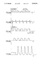
- FIGS. 4A to 4E the interrelationship of physiological parameters and the operation of the system of FIG. 1 is illustrated. From top to bottom, the traces represent the aortic pressure A O , the electrocardiogram ECG, the square wave SQ activating the solenoid of valve 56, the ventilation breath Q v and the cardiac output Q F as measured by an electromagnetic flow probe.
- the operation of system 10 commences at time T. Before this time aortic pressure A o is low, indicating an insufficiency in cardiac output such as may be present in a patient with circulatory disease.
- the occurrence of a first QRS complex in the ECG following time T triggers the beginning of a time delay interval t d .
- a square wave is provided to the solenoid of valve 56, thus opening valve 56.
- Valve 56 remains open for a period of time t ip (an inspiratory plateau time of typically 120 ms) determined by microcomputer 12.
- t ip an inspiratory plateau time of typically 120 ms
- Another square wave delayed by time t d and of width t ip is provided.
- the resulting pressure pulses in line 62 cause the patient's respiration to change from that of the normal respiratory cycle prior to time T to that of short, high frequency breaths occurring at a rate equal to that of the cardiac rate after time T.
- a substantial increase in cardiac output Q F is observed.
- System 10 by suitable programming of microcomputer 12 (which is either manually selectable through information provided at keyboard 30, or may be automatically determined), can operate in a mode wherein one respiration pulse is provided for every N cardiac cycles. Typically N may be equal to 2.
- N may be equal to 2.
- the transition from 1:1 to 1:2 operation occurs at time U.
- the 1:2 mode there is a solenoid square wave SQ provided for every other QRS complex of the ECG waveform.
- the respiration Q v follows the solenoid square wave SQ.
- a 1:2 mode is most appropriate when the patient has a rather rapid heartbeat. Due to inertia associated with the bulk transport of gas in the lungs, it is preferable that system 10 operates at an output pulse rate of approximately 40-60 per minute. Thus, if the patient has a heart rate greater than approximately 85 bpm, operation in the 1:2 mode may be appropriate. As illustrated in FIGS. 5A to 5E, the cardiac output Q F increases even further when the system is switched from the 1:1 mode to the 1:2 mode.
- a program for execution by microprocessor 20 of microcomputer 12 may be loaded from disk (not shown) into RAM 16 or may be permanently stored in ROM 18.
- the program is started by initializing all registers.
- An initial screen display is provided on display unit 28 so that data concerning the patient can be input to the system using keyboard 30 at step 102.
- Appropriate fields for the patient's name and other relevant data, (e.g. the date, the time, ECG lead selection etc.) are provided.
- a switchover to a physiologic display occurs at step 104.
- the electrocardiograph leads have been connected to the patient, the physician may view the patient's electrocardiogram on display 28.
- the display may include a digital read-out of the patient's pulse rate.
- a loop (not separately shown) for monitoring the output of the continuous cardiac output monitor 66, which should have been connected to the patient, is started. As described above with respect to FIG. 2A, monitoring is accomplished by adding the entries in a first in/first out memory to determine the cardiac output of the patient. This loop operates continuously from this point forward with the current value being accessed from time to time as described below.
- Microcomputer 12 may be programmed so that if the continuous cardiac output monitor 66 has not been connected, only continuous manual operation is permitted.
- a control mode and physician-selected control data may be entered.
- a decision may be made at this point to utilize manual control.
- the physician will enter a value for N of, for example, one or two to select the 1:1 or 1:2 mode respectively as described above.
- selected values for t d and t ip in milliseconds, may be entered. Default values may be provided which are automatically entered if the data are not changed. After this data, which are placed in appropriate fields on the display of display unit 28, is checked, it is entered.
- the current value of cardiocirculatory output Q n is stored and system 10 starts to provide cardiocirculatory assistance at step 110.
- step 112 There is a delay at step 112 of approximately fifteen seconds to allow the system to operate and bring the patient to a new state of equilibrium.
- step 114 a check is made to determine whether the output of continuous cardiac output monitor 66 (provided continuously by the loop initiated at step 106) indicates that the cardiac output of the patient is less than or equal to that just prior to the start of the assist at step 110. If for some reason the cardiac output has not increased, the assist is terminated at step 116 and an alarm is activated in the form of an audio tone emitted by display unit 28 as well as an appropriate visual alarm indication thereon (step 118). Thus, if the operation of system 10 does not provide increased cardiac output, the system operator is immediately alerted. It is then necessary either to restart the system and select different control data, or to check for the possibility of a system malfunction.
- the program branches to step 120 where a determination is made as to whether the manual or automatic mode was selected. Assuming that the manual mode was selected, the program branches to step 121 where the output of the continuous cardiac output monitor 66 (as determined by the loop continuously running from the time of execution of step 106) is continuously monitored. As long as cardiac output is greater than 0.7 times the assisted cardiac output determined after step 114, operation of the system continues without any alarm being produced. This allows for some decrease in the assisted cardiac output due to, for example, the patient falling asleep. However, if cardiac output does decrease below 0.7 times the assisted value, the program branches to step 118 and the alarm is sounded. In this case, cardiocirculatory assistance is not automatically terminated.
- step 122 it is advantageous to provide a program interrupt at some point, such as during monitoring by step 122 so that the input data can be manually adjusted using the keyboard 30 to optimize cardiac output. This is advantageously accomplished while the system is providing circulatory assist and cardiac output is being monitored and displayed. After such manual optimization, it is appropriate to re-enter the program starting at step 108.
- step 120 branching from step 120 is to step 122, where a subroutine to automatically optimize delay time t d , described below with respect to FIG. 7, is initiated.
- a subroutine which optimizes the inspiration pulse width t ip is executed at step 124.
- the optimum values of the delay time t d , the pulse width t ip and cardiac output Q F are stored at 126.
- the parameter which has been observed to be most critical in determining the extent of the cardiopulmonary circulatory assist provided is the delay time t d optimized at step 122.
- adjustment of the pulse width t ip at step 124 may also have an influence on cardiac output.
- a counter initialized at a value of 0, is incremented by one count.
- a determination is made as to whether the count is less than a predetermined integer Y which may have a value of, for example, two or three. Assuming that the present count at step 128 is less than the value of Y, the program loops back to step 122.
- the delay t d is then optimized at 122, the width t id is again optimized at 124 and the new optimum values including cardiac output, are stored at 126.
- the count is incremented at step 128.
- the program branches from step 130 to step 132 where the counter is reset.
- cardiac output is continuously monitored to determine whether it has decreased below 0.9 times the optimum value stored at step 126. If this has occurred, the system begins at step 136 to log data into RAM 16.
- the data can also be stored on a disk in a disk drive.
- the data may include pulse rate, the output of the continuous cardiac output monitor 66 or any other relevant physiologic data, which is then available for later interpretation and review by the physician.
- step 122 the delay optimization subroutine of step 122 is described.
- the current value of cardiac output Q n is stored at step 144.
- step 146 an initial value of the delay time t id is incremented by ten milliseconds to provide a new value.
- the initial value may be manually entered at step 108 or may be a default value. In either case, this initial value should be chosen so as to be less than that anticipated as optimum. If this is the case, when the time delay is incremented at step 146 there will be an increase in cardiac output which is then provided as input Q n+1 at step 148.
- a comparison between the cardiac output Q n at step 144 and the cardiac output Q n+1 at step 148 is made after a delay of at least two minutes to allow for establishing a new state of equilibrium.
- the program loops to step 152 where the new value of Q.sub. n is set equal to that determined at step 148. Again the delay time is incremented at step 146 and the latest value of the cardiac output is accessed at step 148. The determination at step 150 is again made. The loop including steps 146, 148, 150 and 152 continues until an increment causes the cardiac output to drop slightly. At this time the program exits from the subroutine at 154.
- the current cardiac output Q n is provided as an input at step 158.
- the initial inspiration plateau time t iip (initial pulse width or inspiration time) is incremented by a fixed value I such as ten milliseconds.
- a new value for the cardiac output Q n+1 is accessed.
- a determination similar to that at step 150 is made. If the cardiac output has not decreased then the program branches to step 166 where the current value of cardiac output Q n+1 is read in as the new value of Q n .
- the pulse width is again incremented at step 160 and the program proceeds to step 162 and to step 164.
- the loop including steps 160, 162, 164 and 166 continues until such time as the cardiac output is determined, at step 164, to have decreased relative to the previous value.
- the subroutine is then exited at 168.
- inspiration pulse width may be decremented by an amount equal to the previous increment so that the cardiac output is maximized.
- this step is not regarded as being critical, particularly with respect to the pulse width.
- the present invention is particularly well suited and most effective in providing cardiopulmonary circulatory assistance in patients having marginal circulation.
- the invention may be of critical importance in prolonging the lives of patients undergoing treatment for severe circulatory disorders.
Abstract
Description
Claims (25)
Priority Applications (9)
| Application Number | Priority Date | Filing Date | Title |
|---|---|---|---|
| US07/175,810 US5020516A (en) | 1988-03-31 | 1988-03-31 | Circulatory assist method and apparatus |
| EP19890905326 EP0407463A4 (en) | 1988-03-31 | 1989-03-31 | Circulatory assist method and apparatus |
| PCT/US1989/001356 WO1989009041A1 (en) | 1988-03-31 | 1989-03-31 | Circulatory assist method and apparatus |
| JP1504999A JPH02504596A (en) | 1988-03-31 | 1989-03-31 | Device for improving cardiac output in patients |
| AU35477/89A AU620097B2 (en) | 1988-03-31 | 1989-03-31 | Circulatory assist method and apparatus |
| FI904784A FI103376B1 (en) | 1988-03-31 | 1990-09-28 | A device for improving the flow rate of a patient's heart |
| DK199002354A DK173598B1 (en) | 1988-03-31 | 1990-09-28 | Apparatus for supporting a patient's respiratory and cardiac function |
| NO90904250A NO904250L (en) | 1988-03-31 | 1990-09-28 | CIRCUIT ASSISTANCE PROCEDURE AND APPARATUS. |
| AU15167/92A AU1516792A (en) | 1988-03-31 | 1992-04-27 | Circulatory assist method and apparatus |
Applications Claiming Priority (1)
| Application Number | Priority Date | Filing Date | Title |
|---|---|---|---|
| US07/175,810 US5020516A (en) | 1988-03-31 | 1988-03-31 | Circulatory assist method and apparatus |
Publications (1)
| Publication Number | Publication Date |
|---|---|
| US5020516A true US5020516A (en) | 1991-06-04 |
Family
ID=22641721
Family Applications (1)
| Application Number | Title | Priority Date | Filing Date |
|---|---|---|---|
| US07/175,810 Expired - Lifetime US5020516A (en) | 1988-03-31 | 1988-03-31 | Circulatory assist method and apparatus |
Country Status (7)
| Country | Link |
|---|---|
| US (1) | US5020516A (en) |
| EP (1) | EP0407463A4 (en) |
| JP (1) | JPH02504596A (en) |
| AU (2) | AU620097B2 (en) |
| DK (1) | DK173598B1 (en) |
| FI (1) | FI103376B1 (en) |
| WO (1) | WO1989009041A1 (en) |
Cited By (71)
| Publication number | Priority date | Publication date | Assignee | Title |
|---|---|---|---|---|
| US5413110A (en) * | 1986-03-31 | 1995-05-09 | Puritan-Bennett Corporation | Computer gated positive expiratory pressure method |
| US5453081A (en) * | 1993-07-12 | 1995-09-26 | Hansen; Craig N. | Pulsator |
| US5549117A (en) * | 1994-05-23 | 1996-08-27 | Enact Health Management Systems | System for monitoring and reporting medical measurements |
| US5569170A (en) * | 1993-07-12 | 1996-10-29 | Electromed, Inc. | Pulsator |
| US5664563A (en) * | 1994-12-09 | 1997-09-09 | Cardiopulmonary Corporation | Pneumatic system |
| US5727559A (en) * | 1994-08-29 | 1998-03-17 | Hynson; James M. | Method and device for increasing hand vascular resistance during blood pressure measurement |
| US5740797A (en) * | 1996-02-23 | 1998-04-21 | University Of Massachusetts | Cardiac synchronized ventilation |
| US5752509A (en) * | 1995-07-10 | 1998-05-19 | Burkhard Lachmann | Artificial ventilation system |
| WO1999036028A1 (en) | 1998-01-14 | 1999-07-22 | Cardiologic Systems, Inc. | Cardiac assist method using an inflatable vest |
| US5931160A (en) * | 1995-12-08 | 1999-08-03 | Cardiopulmonary Corporation | Ventilator control system and method |
| US6123726A (en) * | 1997-07-25 | 2000-09-26 | Seiko Epson Corporation | Portable drive system for artificial heart |
| US6158432A (en) * | 1995-12-08 | 2000-12-12 | Cardiopulmonary Corporation | Ventilator control system and method |
| US6200260B1 (en) | 1997-10-09 | 2001-03-13 | Fore Flow Corporation | Implantable heart assist system |
| US6387037B1 (en) | 1997-10-09 | 2002-05-14 | Orqis Medical Corporation | Implantable heart assist system and method of applying same |
| US6390969B1 (en) | 1997-10-09 | 2002-05-21 | Orqis Medical Corporation | Implantable heart assist system and method of applying same |
| US6463930B2 (en) | 1995-12-08 | 2002-10-15 | James W. Biondi | System for automatically weaning a patient from a ventilator, and method thereof |
| US20030069468A1 (en) * | 1997-10-09 | 2003-04-10 | Bolling Steven F. | Implantable heart assist system and method of applying same |
| US6610004B2 (en) | 1997-10-09 | 2003-08-26 | Orqis Medical Corporation | Implantable heart assist system and method of applying same |
| US20040031490A1 (en) * | 2002-03-18 | 2004-02-19 | Haaga John R. | Safety filtration apparel |
| US20040097849A1 (en) * | 2002-11-15 | 2004-05-20 | Advanced Respiratory, Inc. | Oscillatory chest wall compression device with improved air pulse generator with sweeping oscillating frequency |
| US20040123866A1 (en) * | 1993-11-05 | 2004-07-01 | Michael Berthon-Jones | Determination of patency of the airway |
| US20040171949A1 (en) * | 2003-01-22 | 2004-09-02 | Uscom Limited | Method and system for the determination of blood characteristics |
| EP1491175A1 (en) * | 2003-06-27 | 2004-12-29 | Zoll Medical Corporation | Cardio-pulmonary resuscitation device with feedback from measurement of pulse and/or blood oxygenation |
| US20050085683A1 (en) * | 2003-10-15 | 2005-04-21 | Bolling Steven F. | Implantable heart assist system and method of applying same |
| US20050131385A1 (en) * | 2003-12-12 | 2005-06-16 | Bolling Steven F. | Cannulae for selectively enhancing blood flow |
| US20050187469A1 (en) * | 2002-05-06 | 2005-08-25 | Uscom Pty Ltd. | Blood flow oxygen measurement system and method |
| US20050197551A1 (en) * | 1998-06-03 | 2005-09-08 | Ammar Al-Ali | Stereo pulse oximeter |
| US20050245981A1 (en) * | 2002-07-03 | 2005-11-03 | Phillips Robert A | Pacemaker evaluation method and apparatus |
| US20050277803A1 (en) * | 2004-06-10 | 2005-12-15 | Robert Pecor | Cannulae having reduced flow resistance |
| US20060084877A1 (en) * | 2003-10-17 | 2006-04-20 | Ujhazy Anthony J | Methods and apparatus for heart failure treatment |
| US20060094991A1 (en) * | 2004-11-03 | 2006-05-04 | Rob Walker | Mechanical CPR device with variable resuscitation protocol |
| US20060184199A1 (en) * | 2005-02-14 | 2006-08-17 | O'leary Shawn | Apparatus and methods for reducing bleeding from a cannulation site |
| US20060276717A1 (en) * | 2003-08-13 | 2006-12-07 | Iden Mossanen-Shams | Pulmonary evaluation device |
| US20070225623A1 (en) * | 2006-02-16 | 2007-09-27 | Freeman Gary A | Synchronizing chest compression and ventilation in cardiac resuscitation |
| AU2003227122B2 (en) * | 2002-05-06 | 2008-05-01 | Uscom Limited | Blood flow oxygen measurement system and method |
| US20080202524A1 (en) * | 2007-02-23 | 2008-08-28 | General Electric Company | Setting madatory mechanical ventilation parameters based on patient physiology |
| US20080230062A1 (en) * | 2007-03-23 | 2008-09-25 | General Electric Company | Setting expiratory time in mandatory mechanical ventilation based on a deviation from a stable condition of exhaled gas volumes |
| US20100018530A1 (en) * | 2008-07-25 | 2010-01-28 | Resmed Limited | Method and apparatus for detecting and treating heart failure |
| US20100114220A1 (en) * | 2004-10-25 | 2010-05-06 | Norman A. Paradis | Non-invasive device for synchronizing chest compression and ventilation parameters to residual myocardial activity during cardiopulmonary resuscitation |
| WO2010058398A2 (en) | 2007-03-08 | 2010-05-27 | Sync-Rx, Ltd. | Image processing and tool actuation for medical procedures |
| US20110202101A1 (en) * | 2010-02-12 | 2011-08-18 | Qing Tan | Defibrillator Charging |
| US20110202100A1 (en) * | 2010-02-12 | 2011-08-18 | Qing Tan | Defibrillator Display |
| US8070668B2 (en) | 2006-01-20 | 2011-12-06 | L-Vad Technology | Controlled inflation of a pneumatic L-VAD |
| US8434479B2 (en) | 2009-02-27 | 2013-05-07 | Covidien Lp | Flow rate compensation for transient thermal response of hot-wire anemometers |
| US8460223B2 (en) | 2006-03-15 | 2013-06-11 | Hill-Rom Services Pte. Ltd. | High frequency chest wall oscillation system |
| US20140073889A1 (en) * | 2012-09-12 | 2014-03-13 | Nellcor Puritan Bennett Llc | Systems and methods for determining fluid responsiveness |
| US20140073890A1 (en) * | 2012-09-12 | 2014-03-13 | Nellcor Puritan Bennett Llc | Systems and methods for determining fluid responsiveness |
| US8700130B2 (en) | 2007-03-08 | 2014-04-15 | Sync-Rx, Ltd. | Stepwise advancement of a medical tool |
| US8855744B2 (en) | 2008-11-18 | 2014-10-07 | Sync-Rx, Ltd. | Displaying a device within an endoluminal image stack |
| US9089657B2 (en) | 2011-10-31 | 2015-07-28 | Covidien Lp | Methods and systems for gating user initiated increases in oxygen concentration during ventilation |
| US9095313B2 (en) | 2008-11-18 | 2015-08-04 | Sync-Rx, Ltd. | Accounting for non-uniform longitudinal motion during movement of an endoluminal imaging probe |
| US9101286B2 (en) | 2008-11-18 | 2015-08-11 | Sync-Rx, Ltd. | Apparatus and methods for determining a dimension of a portion of a stack of endoluminal data points |
| US9144394B2 (en) | 2008-11-18 | 2015-09-29 | Sync-Rx, Ltd. | Apparatus and methods for determining a plurality of local calibration factors for an image |
| US9198826B2 (en) | 2010-07-13 | 2015-12-01 | Physio-Control, Inc. | CPR chest compression machine stopping to detect patient recovery |
| US9259543B2 (en) | 2004-10-25 | 2016-02-16 | Zoll Medical Corporation | Non-invasive device for synchronizing chest compression and ventilation parameters to residual myocardial activity during cardiopulmonary resuscitation |
| US9305334B2 (en) | 2007-03-08 | 2016-04-05 | Sync-Rx, Ltd. | Luminal background cleaning |
| US9320677B2 (en) | 2010-02-12 | 2016-04-26 | Zoll Medical Corporation | Defibrillator display including CPR depth information |
| US9375164B2 (en) | 2007-03-08 | 2016-06-28 | Sync-Rx, Ltd. | Co-use of endoluminal data and extraluminal imaging |
| US9629571B2 (en) | 2007-03-08 | 2017-04-25 | Sync-Rx, Ltd. | Co-use of endoluminal data and extraluminal imaging |
| US9855384B2 (en) | 2007-03-08 | 2018-01-02 | Sync-Rx, Ltd. | Automatic enhancement of an image stream of a moving organ and displaying as a movie |
| US9888969B2 (en) | 2007-03-08 | 2018-02-13 | Sync-Rx Ltd. | Automatic quantitative vessel analysis |
| US9974509B2 (en) | 2008-11-18 | 2018-05-22 | Sync-Rx Ltd. | Image super enhancement |
| US10362962B2 (en) | 2008-11-18 | 2019-07-30 | Synx-Rx, Ltd. | Accounting for skipped imaging locations during movement of an endoluminal imaging probe |
| US10420702B2 (en) | 2013-02-20 | 2019-09-24 | Physio-Control, Inc. | CPR quality assessment accounting for pause aspect |
| US10490308B2 (en) | 2013-02-20 | 2019-11-26 | Physio-Control, Inc. | Context-sensitive chest compression fraction measurement for CPR quality assessment |
| US10716528B2 (en) | 2007-03-08 | 2020-07-21 | Sync-Rx, Ltd. | Automatic display of previously-acquired endoluminal images |
| US10748289B2 (en) | 2012-06-26 | 2020-08-18 | Sync-Rx, Ltd | Coregistration of endoluminal data points with values of a luminal-flow-related index |
| US11064964B2 (en) | 2007-03-08 | 2021-07-20 | Sync-Rx, Ltd | Determining a characteristic of a lumen by measuring velocity of a contrast agent |
| US11064903B2 (en) | 2008-11-18 | 2021-07-20 | Sync-Rx, Ltd | Apparatus and methods for mapping a sequence of images to a roadmap image |
| US11197651B2 (en) | 2007-03-08 | 2021-12-14 | Sync-Rx, Ltd. | Identification and presentation of device-to-vessel relative motion |
| US11712399B2 (en) | 2017-04-05 | 2023-08-01 | Stryker Corporation | Chest compression machine systems and methods |
Families Citing this family (4)
| Publication number | Priority date | Publication date | Assignee | Title |
|---|---|---|---|---|
| FI931998A (en) * | 1993-05-03 | 1994-11-04 | Markku Moilanen | Aoterupplivningsapparat |
| CA2732191C (en) * | 1997-08-27 | 2015-04-14 | Zoll Circulation, Inc. | Resuscitation device |
| JP2004261592A (en) * | 2003-02-12 | 2004-09-24 | Nishimura Kikai Kk | External counter pulsation apparatus |
| SE533365C2 (en) * | 2008-02-08 | 2010-09-07 | Igeloesa Life Science Ab | Cardiac rescue procedure and system |
Citations (29)
| Publication number | Priority date | Publication date | Assignee | Title |
|---|---|---|---|---|
| US2241444A (en) * | 1937-10-04 | 1941-05-13 | Joseph H W Bower | Respirator jacket |
| US2529258A (en) * | 1946-07-04 | 1950-11-07 | Lobo Fernando Gonzalez | Apparatus for artificial respiration |
| US3212496A (en) * | 1962-08-21 | 1965-10-19 | United Aircraft Corp | Molecular physiological monitoring system |
| US3266487A (en) * | 1963-06-04 | 1966-08-16 | Sundstrand Corp | Heart pump augmentation system and apparatus |
| US3303841A (en) * | 1964-06-18 | 1967-02-14 | Dennis Clarence | Process and apparatus for pressurizing lower extremities of a patient during ventricular diastole |
| US3410263A (en) * | 1965-05-13 | 1968-11-12 | Westinghouse Electric Corp | Blood-pumping apparatus provided with heart synchronizing means |
| US3426743A (en) * | 1964-02-26 | 1969-02-11 | United Aircraft Corp | Heart pump augmentation system |
| US3430624A (en) * | 1966-09-07 | 1969-03-04 | United Aircraft Corp | Delay time computer for heart pump system |
| US3457909A (en) * | 1966-07-20 | 1969-07-29 | Avco Corp | Heart augmentation system provided with means for measuring intra-arterial pressure |
| US3523529A (en) * | 1968-06-25 | 1970-08-11 | Us Air Force | Oxygen consumption computer |
| US3587562A (en) * | 1968-02-01 | 1971-06-28 | Becton Dickinson Co | Physiological monitoring system |
| US3730173A (en) * | 1970-02-02 | 1973-05-01 | Ahldea Corp | Stimulation method and apparatus for attempting to return a physiological parameter of a patient to normal |
| US3750644A (en) * | 1971-09-09 | 1973-08-07 | Us Army | Cardiac programmer for a coronary blood pump |
| US3835845A (en) * | 1972-10-24 | 1974-09-17 | Medical Innovations Inc | Cardiac synchronization system and method |
| US3923055A (en) * | 1973-11-21 | 1975-12-02 | Hoffmann La Roche | Process and device for controlling the pressure course of a respirator |
| US3966358A (en) * | 1973-11-09 | 1976-06-29 | Medac Gesellschaft Fur Klinische Spezialpraparate Mbh | Pump assembly |
| US3985123A (en) * | 1975-07-17 | 1976-10-12 | Avco Everett Research Laboratory, Inc. | Method and means for monitoring cardiac output |
| US4016871A (en) * | 1975-03-06 | 1977-04-12 | Peter Schiff | Electronic synchronizer-monitor system for controlling the timing of mechanical assistance and pacing of the heart |
| US4077402A (en) * | 1976-06-25 | 1978-03-07 | Benjamin Jr J Malvern | Apparatus for promoting blood circulation |
| US4204524A (en) * | 1977-11-07 | 1980-05-27 | Dov Jaron | Method and apparatus for controlling cardiac assist device |
| US4316391A (en) * | 1979-11-13 | 1982-02-23 | Ultra Med, Inc. | Flow rate measurement |
| US4448192A (en) * | 1982-03-05 | 1984-05-15 | Hewlett Packard Company | Medical ventilator device parametrically controlled for patient ventilation |
| US4509359A (en) * | 1981-12-23 | 1985-04-09 | Gambro Engstrom Ab | Method and apparatus for measuring the concentration of a given component in a gas inhaled and/or exhaled by a patient |
| US4608995A (en) * | 1983-01-19 | 1986-09-02 | Karolinska Institutet Institutionen For Medicinsk Teknik | Method and apparatus for the non-invasive determination of the minute volume of the heart |
| US4632107A (en) * | 1985-07-11 | 1986-12-30 | Nimbus, Inc. | High-frequency jet ventilator |
| US4646733A (en) * | 1984-09-29 | 1987-03-03 | Firma Carl Freudenberg | Endotracheal tube for a high-frequency respirator |
| US4676232A (en) * | 1982-11-19 | 1987-06-30 | Siemens Elema Ab | Respirator and a method of utilizing the respirator to promote blood circulation |
| US4686974A (en) * | 1985-10-18 | 1987-08-18 | Tottori University | Breath synchronized gas-insufflation device and method therefor |
| US4753226A (en) * | 1985-04-01 | 1988-06-28 | Biomedical Engineering Development Center of Sun Yat-Sen University of Medical Science | Combination device for a computerized and enhanced type of external counterpulsation and extra-thoracic cardiac massage apparatus |
Family Cites Families (4)
| Publication number | Priority date | Publication date | Assignee | Title |
|---|---|---|---|---|
| US3078842A (en) * | 1959-06-29 | 1963-02-26 | Reuben F Gray | Resuscitation apparatus |
| US3507146A (en) * | 1968-02-09 | 1970-04-21 | Webb James E | Method and system for respiration analysis |
| US4058855A (en) * | 1976-02-12 | 1977-11-22 | Runge Thomas M | Cardiac pumping device |
| CN85200905U (en) * | 1985-04-01 | 1985-09-10 | 中山医学院 | Microcomputerized enhanced external counter-pulsation for treatment of coronary heart diseases |
-
1988
- 1988-03-31 US US07/175,810 patent/US5020516A/en not_active Expired - Lifetime
-
1989
- 1989-03-31 JP JP1504999A patent/JPH02504596A/en active Granted
- 1989-03-31 AU AU35477/89A patent/AU620097B2/en not_active Ceased
- 1989-03-31 WO PCT/US1989/001356 patent/WO1989009041A1/en active IP Right Grant
- 1989-03-31 EP EP19890905326 patent/EP0407463A4/en not_active Withdrawn
-
1990
- 1990-09-28 FI FI904784A patent/FI103376B1/en not_active IP Right Cessation
- 1990-09-28 DK DK199002354A patent/DK173598B1/en not_active IP Right Cessation
-
1992
- 1992-04-27 AU AU15167/92A patent/AU1516792A/en not_active Abandoned
Patent Citations (29)
| Publication number | Priority date | Publication date | Assignee | Title |
|---|---|---|---|---|
| US2241444A (en) * | 1937-10-04 | 1941-05-13 | Joseph H W Bower | Respirator jacket |
| US2529258A (en) * | 1946-07-04 | 1950-11-07 | Lobo Fernando Gonzalez | Apparatus for artificial respiration |
| US3212496A (en) * | 1962-08-21 | 1965-10-19 | United Aircraft Corp | Molecular physiological monitoring system |
| US3266487A (en) * | 1963-06-04 | 1966-08-16 | Sundstrand Corp | Heart pump augmentation system and apparatus |
| US3426743A (en) * | 1964-02-26 | 1969-02-11 | United Aircraft Corp | Heart pump augmentation system |
| US3303841A (en) * | 1964-06-18 | 1967-02-14 | Dennis Clarence | Process and apparatus for pressurizing lower extremities of a patient during ventricular diastole |
| US3410263A (en) * | 1965-05-13 | 1968-11-12 | Westinghouse Electric Corp | Blood-pumping apparatus provided with heart synchronizing means |
| US3457909A (en) * | 1966-07-20 | 1969-07-29 | Avco Corp | Heart augmentation system provided with means for measuring intra-arterial pressure |
| US3430624A (en) * | 1966-09-07 | 1969-03-04 | United Aircraft Corp | Delay time computer for heart pump system |
| US3587562A (en) * | 1968-02-01 | 1971-06-28 | Becton Dickinson Co | Physiological monitoring system |
| US3523529A (en) * | 1968-06-25 | 1970-08-11 | Us Air Force | Oxygen consumption computer |
| US3730173A (en) * | 1970-02-02 | 1973-05-01 | Ahldea Corp | Stimulation method and apparatus for attempting to return a physiological parameter of a patient to normal |
| US3750644A (en) * | 1971-09-09 | 1973-08-07 | Us Army | Cardiac programmer for a coronary blood pump |
| US3835845A (en) * | 1972-10-24 | 1974-09-17 | Medical Innovations Inc | Cardiac synchronization system and method |
| US3966358A (en) * | 1973-11-09 | 1976-06-29 | Medac Gesellschaft Fur Klinische Spezialpraparate Mbh | Pump assembly |
| US3923055A (en) * | 1973-11-21 | 1975-12-02 | Hoffmann La Roche | Process and device for controlling the pressure course of a respirator |
| US4016871A (en) * | 1975-03-06 | 1977-04-12 | Peter Schiff | Electronic synchronizer-monitor system for controlling the timing of mechanical assistance and pacing of the heart |
| US3985123A (en) * | 1975-07-17 | 1976-10-12 | Avco Everett Research Laboratory, Inc. | Method and means for monitoring cardiac output |
| US4077402A (en) * | 1976-06-25 | 1978-03-07 | Benjamin Jr J Malvern | Apparatus for promoting blood circulation |
| US4204524A (en) * | 1977-11-07 | 1980-05-27 | Dov Jaron | Method and apparatus for controlling cardiac assist device |
| US4316391A (en) * | 1979-11-13 | 1982-02-23 | Ultra Med, Inc. | Flow rate measurement |
| US4509359A (en) * | 1981-12-23 | 1985-04-09 | Gambro Engstrom Ab | Method and apparatus for measuring the concentration of a given component in a gas inhaled and/or exhaled by a patient |
| US4448192A (en) * | 1982-03-05 | 1984-05-15 | Hewlett Packard Company | Medical ventilator device parametrically controlled for patient ventilation |
| US4676232A (en) * | 1982-11-19 | 1987-06-30 | Siemens Elema Ab | Respirator and a method of utilizing the respirator to promote blood circulation |
| US4608995A (en) * | 1983-01-19 | 1986-09-02 | Karolinska Institutet Institutionen For Medicinsk Teknik | Method and apparatus for the non-invasive determination of the minute volume of the heart |
| US4646733A (en) * | 1984-09-29 | 1987-03-03 | Firma Carl Freudenberg | Endotracheal tube for a high-frequency respirator |
| US4753226A (en) * | 1985-04-01 | 1988-06-28 | Biomedical Engineering Development Center of Sun Yat-Sen University of Medical Science | Combination device for a computerized and enhanced type of external counterpulsation and extra-thoracic cardiac massage apparatus |
| US4632107A (en) * | 1985-07-11 | 1986-12-30 | Nimbus, Inc. | High-frequency jet ventilator |
| US4686974A (en) * | 1985-10-18 | 1987-08-18 | Tottori University | Breath synchronized gas-insufflation device and method therefor |
Cited By (194)
| Publication number | Priority date | Publication date | Assignee | Title |
|---|---|---|---|---|
| US5413110A (en) * | 1986-03-31 | 1995-05-09 | Puritan-Bennett Corporation | Computer gated positive expiratory pressure method |
| US5453081A (en) * | 1993-07-12 | 1995-09-26 | Hansen; Craig N. | Pulsator |
| US5569170A (en) * | 1993-07-12 | 1996-10-29 | Electromed, Inc. | Pulsator |
| US8381722B2 (en) | 1993-11-05 | 2013-02-26 | Resmed Limited | Distinguishing between closed and open airway apneas and treating patients accordingly |
| US20100242965A1 (en) * | 1993-11-05 | 2010-09-30 | Michael Berthon-Jones | Distinguishing between closed and open airway apneas and treating patients accordingly |
| US20110011402A1 (en) * | 1993-11-05 | 2011-01-20 | Michael Berthon-Jones | Distinguishing between closed and open airway apneas and treating patients accordingly |
| US7320320B2 (en) * | 1993-11-05 | 2008-01-22 | Resmed Limited | Determination of patency of the airway |
| US20080163873A1 (en) * | 1993-11-05 | 2008-07-10 | Michael Berthon-Jones | Determination of patency of the airway |
| US20040123866A1 (en) * | 1993-11-05 | 2004-07-01 | Michael Berthon-Jones | Determination of patency of the airway |
| US8752547B2 (en) | 1993-11-05 | 2014-06-17 | Resmed Limited | Distinguishing between closed and open airway apneas and treating patients accordingly |
| US8360060B2 (en) | 1993-11-05 | 2013-01-29 | Resmed Limited | Distinguishing between closed and open airway apneas and treating patients accordingly |
| US7730886B2 (en) | 1993-11-05 | 2010-06-08 | Resmed Limited | Determination of patency of the airway |
| US5626144A (en) * | 1994-05-23 | 1997-05-06 | Enact Health Management Systems | System for monitoring and reporting medical measurements |
| US5732709A (en) * | 1994-05-23 | 1998-03-31 | Enact Health Management Systems | System for monitoring and reporting medical measurements |
| US5704366A (en) * | 1994-05-23 | 1998-01-06 | Enact Health Management Systems | System for monitoring and reporting medical measurements |
| US5549117A (en) * | 1994-05-23 | 1996-08-27 | Enact Health Management Systems | System for monitoring and reporting medical measurements |
| US5727559A (en) * | 1994-08-29 | 1998-03-17 | Hynson; James M. | Method and device for increasing hand vascular resistance during blood pressure measurement |
| US5664563A (en) * | 1994-12-09 | 1997-09-09 | Cardiopulmonary Corporation | Pneumatic system |
| US5752509A (en) * | 1995-07-10 | 1998-05-19 | Burkhard Lachmann | Artificial ventilation system |
| US6158432A (en) * | 1995-12-08 | 2000-12-12 | Cardiopulmonary Corporation | Ventilator control system and method |
| US7017574B2 (en) | 1995-12-08 | 2006-03-28 | Cardiopulmonary Corporation | System for automatically weaning a patient from a ventilator, and method thereof |
| US6463930B2 (en) | 1995-12-08 | 2002-10-15 | James W. Biondi | System for automatically weaning a patient from a ventilator, and method thereof |
| US7334578B2 (en) | 1995-12-08 | 2008-02-26 | Cardiopulmonary Corporation | System for automatically weaning a patient from a ventilator, and method thereof |
| US6584973B1 (en) | 1995-12-08 | 2003-07-01 | Cardiopulmonary Corporation | Ventilator control system and method |
| US6668829B2 (en) | 1995-12-08 | 2003-12-30 | Cardiopulmonary Corporation | System for automatically weaning a patient from a ventilator, and method thereof |
| US5931160A (en) * | 1995-12-08 | 1999-08-03 | Cardiopulmonary Corporation | Ventilator control system and method |
| US20050051167A1 (en) * | 1995-12-08 | 2005-03-10 | Biondi James W. | System for automatically weaning a patient from a ventilator, and method thereof |
| US5740797A (en) * | 1996-02-23 | 1998-04-21 | University Of Massachusetts | Cardiac synchronized ventilation |
| US6123726A (en) * | 1997-07-25 | 2000-09-26 | Seiko Epson Corporation | Portable drive system for artificial heart |
| US6390969B1 (en) | 1997-10-09 | 2002-05-21 | Orqis Medical Corporation | Implantable heart assist system and method of applying same |
| US7125376B2 (en) | 1997-10-09 | 2006-10-24 | Orqis Medical Corporation | Implantable heart assist system and method of applying same |
| US7588531B2 (en) | 1997-10-09 | 2009-09-15 | Orqis Medical Corporation | Implantable heart assist system and method of applying same |
| US7458929B2 (en) | 1997-10-09 | 2008-12-02 | Orqis Medical Corporation | Implantable heart assist system and method of applying same |
| US8900115B2 (en) | 1997-10-09 | 2014-12-02 | Thoratec Corporation | Implantable heart assist system and method of applying same |
| US20040236172A1 (en) * | 1997-10-09 | 2004-11-25 | Bolling Steven F. | Implantable heart assist system and method of applying same |
| US7591778B2 (en) | 1997-10-09 | 2009-09-22 | Orqis Medical Corporation | Implantable heart assist system and method of applying same |
| US7614997B2 (en) | 1997-10-09 | 2009-11-10 | Orqis Medical Corporation | Implantable heart assist system and method of applying same |
| US6200260B1 (en) | 1997-10-09 | 2001-03-13 | Fore Flow Corporation | Implantable heart assist system |
| US6299575B1 (en) | 1997-10-09 | 2001-10-09 | Orqis Medical Corporation | Implantable heart assist system |
| US6685621B2 (en) | 1997-10-09 | 2004-02-03 | Orois Medical Corporation | Implantable heart assist system and method of applying same |
| US6889082B2 (en) | 1997-10-09 | 2005-05-03 | Orqis Medical Corporation | Implantable heart assist system and method of applying same |
| US6610004B2 (en) | 1997-10-09 | 2003-08-26 | Orqis Medical Corporation | Implantable heart assist system and method of applying same |
| US6387037B1 (en) | 1997-10-09 | 2002-05-14 | Orqis Medical Corporation | Implantable heart assist system and method of applying same |
| US7513863B2 (en) | 1997-10-09 | 2009-04-07 | Orqis Medical Corporation | Implantable heart assist system and method of applying same |
| US20060276681A1 (en) * | 1997-10-09 | 2006-12-07 | Bolling Steven F | Implantable heart assist system and method of applying same |
| US20050256363A1 (en) * | 1997-10-09 | 2005-11-17 | Bolling Steven F | Implantable heart assist system and method of applying same |
| US7144365B2 (en) | 1997-10-09 | 2006-12-05 | Orqis Medical Corporation | Implantable heart assist system and method of applying same |
| US20030069468A1 (en) * | 1997-10-09 | 2003-04-10 | Bolling Steven F. | Implantable heart assist system and method of applying same |
| US6428464B1 (en) | 1997-10-09 | 2002-08-06 | Orqis Medical Corporation | Implantable heart assist system |
| US20060270892A1 (en) * | 1997-10-09 | 2006-11-30 | Bolling Steven F | Implantable heart assist system and method of applying same |
| US7993260B2 (en) | 1997-10-09 | 2011-08-09 | Thoratec Corporation | Implantable heart assist system and method of applying same |
| US20040116768A1 (en) * | 1997-10-09 | 2004-06-17 | Bolling Steven F. | Implantable heart assist system and method of applying same |
| US6179793B1 (en) | 1998-01-14 | 2001-01-30 | Revivant Corporation | Cardiac assist method using an inflatable vest |
| US6752771B2 (en) | 1998-01-14 | 2004-06-22 | Revivant Corporation | Cardiac assist method using an inflatable vest |
| WO1999036028A1 (en) | 1998-01-14 | 1999-07-22 | Cardiologic Systems, Inc. | Cardiac assist method using an inflatable vest |
| US7891355B2 (en) * | 1998-06-03 | 2011-02-22 | Masimo Corporation | Physiological monitor |
| US8721541B2 (en) | 1998-06-03 | 2014-05-13 | Masimo Corporation | Physiological monitor |
| US8364223B2 (en) | 1998-06-03 | 2013-01-29 | Masimo Corporation | Physiological monitor |
| US7899507B2 (en) | 1998-06-03 | 2011-03-01 | Masimo Corporation | Physiological monitor |
| US20060258924A1 (en) * | 1998-06-03 | 2006-11-16 | Ammar Al-Ali | Physiological monitor |
| US20060281983A1 (en) * | 1998-06-03 | 2006-12-14 | Ammar Al-Ali | Physiological monitor |
| US7894868B2 (en) * | 1998-06-03 | 2011-02-22 | Masimo Corporation | Physiological monitor |
| US20050197551A1 (en) * | 1998-06-03 | 2005-09-08 | Ammar Al-Ali | Stereo pulse oximeter |
| US9492110B2 (en) | 1998-06-03 | 2016-11-15 | Masimo Corporation | Physiological monitor |
| US10335072B2 (en) | 1998-06-03 | 2019-07-02 | Masimo Corporation | Physiological monitor |
| US20060258923A1 (en) * | 1998-06-03 | 2006-11-16 | Ammar Al-Ali | Physiological monitor |
| US8255028B2 (en) | 1998-06-03 | 2012-08-28 | Masimo Corporation, Inc. | Physiological monitor |
| US20060258925A1 (en) * | 1998-06-03 | 2006-11-16 | Ammar Al-Ali | Physiological monitor |
| US7761128B2 (en) * | 1998-06-03 | 2010-07-20 | Masimo Corporation | Physiological monitor |
| US7331921B2 (en) | 2002-02-15 | 2008-02-19 | Orqis Medical Corporation | Implantable heart assist system and method of applying same |
| US20040236173A1 (en) * | 2002-02-15 | 2004-11-25 | Anthony Viole | Implantable heart assist system and method of applying same |
| US20040031490A1 (en) * | 2002-03-18 | 2004-02-19 | Haaga John R. | Safety filtration apparel |
| AU2003227122B2 (en) * | 2002-05-06 | 2008-05-01 | Uscom Limited | Blood flow oxygen measurement system and method |
| US7338447B2 (en) * | 2002-05-06 | 2008-03-04 | Uscom Pty Ltd | Blood flow oxygen measurement system and method |
| US20050187469A1 (en) * | 2002-05-06 | 2005-08-25 | Uscom Pty Ltd. | Blood flow oxygen measurement system and method |
| US7630766B2 (en) | 2002-07-03 | 2009-12-08 | Uscom Limited | Exercise responsive pacemaker tuning method using Doppler blood flow measurements to adjust pacing for optimized flow |
| US20050245981A1 (en) * | 2002-07-03 | 2005-11-03 | Phillips Robert A | Pacemaker evaluation method and apparatus |
| US20060009718A1 (en) * | 2002-11-15 | 2006-01-12 | Van Brunt Nicholas P | Air pulse generator with multiple operating modes |
| US7582065B2 (en) | 2002-11-15 | 2009-09-01 | Hill-Rom Services, Inc. | Air pulse generator with multiple operating modes |
| US7491182B2 (en) | 2002-11-15 | 2009-02-17 | Hill-Rom Services, Inc. | High frequency chest wall oscillation apparatus having plurality of modes |
| US20040097842A1 (en) * | 2002-11-15 | 2004-05-20 | Advanced Respiratory, Inc. | Oscillatory chest wall compression device with improved air pulse generator with improved user interface |
| US20040097849A1 (en) * | 2002-11-15 | 2004-05-20 | Advanced Respiratory, Inc. | Oscillatory chest wall compression device with improved air pulse generator with sweeping oscillating frequency |
| US7425203B2 (en) * | 2002-11-15 | 2008-09-16 | Hill-Rom Services, Inc. | Oscillatory chest wall compression device with improved air pulse generator with improved user interface |
| US20040171949A1 (en) * | 2003-01-22 | 2004-09-02 | Uscom Limited | Method and system for the determination of blood characteristics |
| US7789835B2 (en) | 2003-01-22 | 2010-09-07 | Uscom Limited | Methods and systems for determining cardiac output based on a valve cross sectional area estimate |
| US7190999B2 (en) | 2003-06-27 | 2007-03-13 | Zoll Medical Corporation | Cardio-pulmonary resuscitation device with feedback from measurement of pulse and/or blood oxygenation |
| US20040267324A1 (en) * | 2003-06-27 | 2004-12-30 | Frederick Geheb | Cardio-pulmonary resuscitation device with feedback from measurement of pulse and/or blood oxygenation |
| EP1491175A1 (en) * | 2003-06-27 | 2004-12-29 | Zoll Medical Corporation | Cardio-pulmonary resuscitation device with feedback from measurement of pulse and/or blood oxygenation |
| US7658717B2 (en) * | 2003-08-13 | 2010-02-09 | Iden Mossanen-Shams | Pulmonary evaluation device |
| US20060276717A1 (en) * | 2003-08-13 | 2006-12-07 | Iden Mossanen-Shams | Pulmonary evaluation device |
| US20050085683A1 (en) * | 2003-10-15 | 2005-04-21 | Bolling Steven F. | Implantable heart assist system and method of applying same |
| US9283341B2 (en) | 2003-10-17 | 2016-03-15 | Resmed Limited | Methods and apparatus for heart failure treatment |
| US10856802B2 (en) | 2003-10-17 | 2020-12-08 | ResMed Pty Ltd | Methods and apparatus for heart failure treatment |
| US20100258126A1 (en) * | 2003-10-17 | 2010-10-14 | Anthony John Ujhazy | Methods and apparatus for heart failure treatment |
| US20060084877A1 (en) * | 2003-10-17 | 2006-04-20 | Ujhazy Anthony J | Methods and apparatus for heart failure treatment |
| US20070135724A1 (en) * | 2003-10-17 | 2007-06-14 | Ujhazy Anthony J | Methods and apparatus for heart failure treatment |
| US20100043795A1 (en) * | 2003-10-17 | 2010-02-25 | Anthony John Ujhazy | Methods and apparatus for heart failure treatment |
| US8356594B2 (en) | 2003-10-17 | 2013-01-22 | Resmed Limited | Methods and apparatus for heart failure treatment |
| US20050131385A1 (en) * | 2003-12-12 | 2005-06-16 | Bolling Steven F. | Cannulae for selectively enhancing blood flow |
| US7445592B2 (en) | 2004-06-10 | 2008-11-04 | Orqis Medical Corporation | Cannulae having reduced flow resistance |
| US20050277803A1 (en) * | 2004-06-10 | 2005-12-15 | Robert Pecor | Cannulae having reduced flow resistance |
| US10555870B2 (en) | 2004-10-25 | 2020-02-11 | Zoll Medical Corporation | Non-invasive device for synchronizing chest compression and ventilation parameters to residual myocardial activity during cardiopulmonary resuscitation |
| US9259543B2 (en) | 2004-10-25 | 2016-02-16 | Zoll Medical Corporation | Non-invasive device for synchronizing chest compression and ventilation parameters to residual myocardial activity during cardiopulmonary resuscitation |
| US8870797B2 (en) * | 2004-10-25 | 2014-10-28 | Norman A. Paradis | Non-invasive device for synchronizing chest compression and ventilation parameters to residual myocardial activity during cardiopulmonary resuscitation |
| US9833378B2 (en) | 2004-10-25 | 2017-12-05 | Zoll Medical Corporation | Non-invasive device for synchronizing chest compression and ventilation parameters to residual myocardial activity during cardiopulmonary resuscitation |
| US11419786B2 (en) | 2004-10-25 | 2022-08-23 | Zoll Medical Corporation | Non-invasive device for synchronizing chest compression and ventilation parameters to residual myocardial activity during cardiopulmonary resuscitation |
| US20100114220A1 (en) * | 2004-10-25 | 2010-05-06 | Norman A. Paradis | Non-invasive device for synchronizing chest compression and ventilation parameters to residual myocardial activity during cardiopulmonary resuscitation |
| US20060094991A1 (en) * | 2004-11-03 | 2006-05-04 | Rob Walker | Mechanical CPR device with variable resuscitation protocol |
| US9078804B2 (en) | 2004-11-03 | 2015-07-14 | Physio-Control, Inc. | Mechanical CPR device with variable resuscitation protocol |
| US8343081B2 (en) * | 2004-11-03 | 2013-01-01 | Physio-Control, Inc. | Mechanical CPR device with variable resuscitation protocol |
| US10143620B2 (en) | 2004-11-03 | 2018-12-04 | Physio-Control, Inc. | Mechanical CPR device with variable resuscitation protocol |
| US20080097258A1 (en) * | 2004-11-03 | 2008-04-24 | Rob Walker | Mechanical CPR Device With Variable Resuscitation Protocol |
| US8795208B2 (en) | 2004-11-03 | 2014-08-05 | Physio-Control, Inc. | Mechanical CPR device with variable resuscitation protocol |
| US20060184199A1 (en) * | 2005-02-14 | 2006-08-17 | O'leary Shawn | Apparatus and methods for reducing bleeding from a cannulation site |
| US8070668B2 (en) | 2006-01-20 | 2011-12-06 | L-Vad Technology | Controlled inflation of a pneumatic L-VAD |
| EP2308447A2 (en) | 2006-02-16 | 2011-04-13 | Zoll Medical Corporation | Synchronizing chest compression and ventilation in cardiac resuscitation |
| US20070225623A1 (en) * | 2006-02-16 | 2007-09-27 | Freeman Gary A | Synchronizing chest compression and ventilation in cardiac resuscitation |
| EP2305203A2 (en) | 2006-02-16 | 2011-04-06 | Zoll Medical Corporation | Synchronizing chest compression and ventilation in cardiac resuscitation |
| US9174064B2 (en) | 2006-02-16 | 2015-11-03 | Zoll Medical Corporation | Synchronizing chest compression and ventilation in cardiac resuscitation |
| CN102415938B (en) * | 2006-02-16 | 2015-05-20 | Zoll医疗公司 | Synchronizing chest compression and ventilation in cardiac resuscitation |
| US8105249B2 (en) | 2006-02-16 | 2012-01-31 | Zoll Medical Corporation | Synchronizing chest compression and ventilation in cardiac resuscitation |
| US20110224587A1 (en) * | 2006-02-16 | 2011-09-15 | Freeman Gary A | Synchronizing Chest Compression and Ventilation in Cardiac Resuscitation |
| US11839586B2 (en) | 2006-02-16 | 2023-12-12 | Zoll Medical Corporation | Synchronizing chest compression and ventilation in cardiac resuscitation |
| US10251811B2 (en) | 2006-02-16 | 2019-04-09 | Zoll Medical Corporation | Synchronizing chest compression and ventilation in cardiac resuscitation |
| US8460223B2 (en) | 2006-03-15 | 2013-06-11 | Hill-Rom Services Pte. Ltd. | High frequency chest wall oscillation system |
| US9968511B2 (en) | 2006-03-15 | 2018-05-15 | Hill-Rom Services Pte. Ltd. | High frequency chest wall oscillation system |
| US11110028B2 (en) | 2006-03-15 | 2021-09-07 | Hill-Rom Services Pte. Ltd. | High frequency chest wall oscillation system |
| US20080202524A1 (en) * | 2007-02-23 | 2008-08-28 | General Electric Company | Setting madatory mechanical ventilation parameters based on patient physiology |
| US9008754B2 (en) | 2007-03-08 | 2015-04-14 | Sync-Rx, Ltd. | Automatic correction and utilization of a vascular roadmap comprising a tool |
| US9968256B2 (en) | 2007-03-08 | 2018-05-15 | Sync-Rx Ltd. | Automatic identification of a tool |
| US11197651B2 (en) | 2007-03-08 | 2021-12-14 | Sync-Rx, Ltd. | Identification and presentation of device-to-vessel relative motion |
| US11179038B2 (en) | 2007-03-08 | 2021-11-23 | Sync-Rx, Ltd | Automatic stabilization of a frames of image stream of a moving organ having intracardiac or intravascular tool in the organ that is displayed in movie format |
| US8781193B2 (en) | 2007-03-08 | 2014-07-15 | Sync-Rx, Ltd. | Automatic quantitative vessel analysis |
| WO2010058398A2 (en) | 2007-03-08 | 2010-05-27 | Sync-Rx, Ltd. | Image processing and tool actuation for medical procedures |
| US9008367B2 (en) | 2007-03-08 | 2015-04-14 | Sync-Rx, Ltd. | Apparatus and methods for reducing visibility of a periphery of an image stream |
| US8700130B2 (en) | 2007-03-08 | 2014-04-15 | Sync-Rx, Ltd. | Stepwise advancement of a medical tool |
| US9014453B2 (en) | 2007-03-08 | 2015-04-21 | Sync-Rx, Ltd. | Automatic angiogram detection |
| US8693756B2 (en) | 2007-03-08 | 2014-04-08 | Sync-Rx, Ltd. | Automatic reduction of interfering elements from an image stream of a moving organ |
| US11064964B2 (en) | 2007-03-08 | 2021-07-20 | Sync-Rx, Ltd | Determining a characteristic of a lumen by measuring velocity of a contrast agent |
| US20100171819A1 (en) * | 2007-03-08 | 2010-07-08 | Sync-Rx, Ltd. | Automatic reduction of interfering elements from an image stream of a moving organ |
| US10716528B2 (en) | 2007-03-08 | 2020-07-21 | Sync-Rx, Ltd. | Automatic display of previously-acquired endoluminal images |
| US20100220917A1 (en) * | 2007-03-08 | 2010-09-02 | Sync-Rx, Ltd. | Automatic generation of a vascular skeleton |
| US10499814B2 (en) | 2007-03-08 | 2019-12-10 | Sync-Rx, Ltd. | Automatic generation and utilization of a vascular roadmap |
| US20100290693A1 (en) * | 2007-03-08 | 2010-11-18 | Sync-Rx, Ltd. | Location-sensitive cursor control and its use for vessel analysis |
| US10307061B2 (en) | 2007-03-08 | 2019-06-04 | Sync-Rx, Ltd. | Automatic tracking of a tool upon a vascular roadmap |
| US9216065B2 (en) | 2007-03-08 | 2015-12-22 | Sync-Rx, Ltd. | Forming and displaying a composite image |
| US8670603B2 (en) | 2007-03-08 | 2014-03-11 | Sync-Rx, Ltd. | Apparatus and methods for masking a portion of a moving image stream |
| US8542900B2 (en) | 2007-03-08 | 2013-09-24 | Sync-Rx Ltd. | Automatic reduction of interfering elements from an image stream of a moving organ |
| US10226178B2 (en) | 2007-03-08 | 2019-03-12 | Sync-Rx Ltd. | Automatic reduction of visibility of portions of an image |
| US9305334B2 (en) | 2007-03-08 | 2016-04-05 | Sync-Rx, Ltd. | Luminal background cleaning |
| US9308052B2 (en) | 2007-03-08 | 2016-04-12 | Sync-Rx, Ltd. | Pre-deployment positioning of an implantable device within a moving organ |
| US8290228B2 (en) | 2007-03-08 | 2012-10-16 | Sync-Rx, Ltd. | Location-sensitive cursor control and its use for vessel analysis |
| US9375164B2 (en) | 2007-03-08 | 2016-06-28 | Sync-Rx, Ltd. | Co-use of endoluminal data and extraluminal imaging |
| US8463007B2 (en) | 2007-03-08 | 2013-06-11 | Sync-Rx, Ltd. | Automatic generation of a vascular skeleton |
| US9629571B2 (en) | 2007-03-08 | 2017-04-25 | Sync-Rx, Ltd. | Co-use of endoluminal data and extraluminal imaging |
| US9717415B2 (en) | 2007-03-08 | 2017-08-01 | Sync-Rx, Ltd. | Automatic quantitative vessel analysis at the location of an automatically-detected tool |
| US9888969B2 (en) | 2007-03-08 | 2018-02-13 | Sync-Rx Ltd. | Automatic quantitative vessel analysis |
| US9855384B2 (en) | 2007-03-08 | 2018-01-02 | Sync-Rx, Ltd. | Automatic enhancement of an image stream of a moving organ and displaying as a movie |
| US20080230062A1 (en) * | 2007-03-23 | 2008-09-25 | General Electric Company | Setting expiratory time in mandatory mechanical ventilation based on a deviation from a stable condition of exhaled gas volumes |
| US20100018530A1 (en) * | 2008-07-25 | 2010-01-28 | Resmed Limited | Method and apparatus for detecting and treating heart failure |
| US8844525B2 (en) | 2008-07-25 | 2014-09-30 | Resmed Limited | Method and apparatus for detecting and treating heart failure |
| US8855744B2 (en) | 2008-11-18 | 2014-10-07 | Sync-Rx, Ltd. | Displaying a device within an endoluminal image stack |
| US9974509B2 (en) | 2008-11-18 | 2018-05-22 | Sync-Rx Ltd. | Image super enhancement |
| US9144394B2 (en) | 2008-11-18 | 2015-09-29 | Sync-Rx, Ltd. | Apparatus and methods for determining a plurality of local calibration factors for an image |
| US11883149B2 (en) | 2008-11-18 | 2024-01-30 | Sync-Rx Ltd. | Apparatus and methods for mapping a sequence of images to a roadmap image |
| US11064903B2 (en) | 2008-11-18 | 2021-07-20 | Sync-Rx, Ltd | Apparatus and methods for mapping a sequence of images to a roadmap image |
| US9095313B2 (en) | 2008-11-18 | 2015-08-04 | Sync-Rx, Ltd. | Accounting for non-uniform longitudinal motion during movement of an endoluminal imaging probe |
| US9101286B2 (en) | 2008-11-18 | 2015-08-11 | Sync-Rx, Ltd. | Apparatus and methods for determining a dimension of a portion of a stack of endoluminal data points |
| US10362962B2 (en) | 2008-11-18 | 2019-07-30 | Synx-Rx, Ltd. | Accounting for skipped imaging locations during movement of an endoluminal imaging probe |
| US8434479B2 (en) | 2009-02-27 | 2013-05-07 | Covidien Lp | Flow rate compensation for transient thermal response of hot-wire anemometers |
| US8905024B2 (en) | 2009-02-27 | 2014-12-09 | Covidien Lp | Flow rate compensation for transient thermal response of hot-wire anemometers |
| US8880166B2 (en) | 2010-02-12 | 2014-11-04 | Zoll Medical Corporation | Defibrillator display |
| US10813560B2 (en) | 2010-02-12 | 2020-10-27 | Zoll Medical Corporation | Defibrillator charging |
| US9788734B2 (en) | 2010-02-12 | 2017-10-17 | Zoll Medical Corporation | Defibrillator display |
| US9320677B2 (en) | 2010-02-12 | 2016-04-26 | Zoll Medical Corporation | Defibrillator display including CPR depth information |
| US11810655B2 (en) | 2010-02-12 | 2023-11-07 | Zoll Medical Corporation | Defibrillator charging |
| US10143387B2 (en) | 2010-02-12 | 2018-12-04 | Zoll Medical Corporation | Defibrillator charging |
| US10426696B2 (en) | 2010-02-12 | 2019-10-01 | Zoll Medical Corporation | Defibrillator display including CPR depth information |
| US20110202100A1 (en) * | 2010-02-12 | 2011-08-18 | Qing Tan | Defibrillator Display |
| US9289134B2 (en) | 2010-02-12 | 2016-03-22 | Zoll Medical Corporation | Defibrillator display |
| US10893812B2 (en) | 2010-02-12 | 2021-01-19 | Zoll Medical Corporation | Defibrillator display |
| US20110202101A1 (en) * | 2010-02-12 | 2011-08-18 | Qing Tan | Defibrillator Charging |
| US11554074B2 (en) | 2010-02-12 | 2023-01-17 | Zoll Medical Corporation | Defibrillator display including CPR depth information |
| US10265242B2 (en) | 2010-07-13 | 2019-04-23 | Physio-Control, Inc. | CPR chest compression machine stopping to detect patient recovery |
| US11660249B2 (en) | 2010-07-13 | 2023-05-30 | Physio-Control, Inc. | CPR chest compression machine stopping to detect patient recovery |
| US9198826B2 (en) | 2010-07-13 | 2015-12-01 | Physio-Control, Inc. | CPR chest compression machine stopping to detect patient recovery |
| US9089657B2 (en) | 2011-10-31 | 2015-07-28 | Covidien Lp | Methods and systems for gating user initiated increases in oxygen concentration during ventilation |
| US10748289B2 (en) | 2012-06-26 | 2020-08-18 | Sync-Rx, Ltd | Coregistration of endoluminal data points with values of a luminal-flow-related index |
| US10984531B2 (en) | 2012-06-26 | 2021-04-20 | Sync-Rx, Ltd. | Determining a luminal-flow-related index using blood velocity determination |
| US20140073890A1 (en) * | 2012-09-12 | 2014-03-13 | Nellcor Puritan Bennett Llc | Systems and methods for determining fluid responsiveness |
| US20140073889A1 (en) * | 2012-09-12 | 2014-03-13 | Nellcor Puritan Bennett Llc | Systems and methods for determining fluid responsiveness |
| US10420702B2 (en) | 2013-02-20 | 2019-09-24 | Physio-Control, Inc. | CPR quality assessment accounting for pause aspect |
| US10490308B2 (en) | 2013-02-20 | 2019-11-26 | Physio-Control, Inc. | Context-sensitive chest compression fraction measurement for CPR quality assessment |
| US11712399B2 (en) | 2017-04-05 | 2023-08-01 | Stryker Corporation | Chest compression machine systems and methods |
Also Published As
| Publication number | Publication date |
|---|---|
| EP0407463A4 (en) | 1991-06-05 |
| EP0407463A1 (en) | 1991-01-16 |
| DK235490D0 (en) | 1990-09-28 |
| JPH0412979B2 (en) | 1992-03-06 |
| WO1989009041A1 (en) | 1989-10-05 |
| FI103376B (en) | 1999-06-30 |
| DK235490A (en) | 1990-09-28 |
| FI103376B1 (en) | 1999-06-30 |
| JPH02504596A (en) | 1990-12-27 |
| AU620097B2 (en) | 1992-02-13 |
| AU1516792A (en) | 1992-06-25 |
| FI904784A0 (en) | 1990-09-28 |
| AU3547789A (en) | 1989-10-16 |
| DK173598B1 (en) | 2001-04-23 |
Similar Documents
| Publication | Publication Date | Title |
|---|---|---|
| US5020516A (en) | Circulatory assist method and apparatus | |
| US11857302B2 (en) | Method, logic unit and system for determining a parameter representative for the patient's volume responsiveness | |
| US5413110A (en) | Computer gated positive expiratory pressure method | |
| US5377671A (en) | Cardiac synchronous ventilation | |
| JPH06125Y2 (en) | Computer gated pressure device for controlling patient exhalation | |
| US7314449B2 (en) | Apparatus for determining cardiovascular parameters | |
| US3923055A (en) | Process and device for controlling the pressure course of a respirator | |
| US20130158375A1 (en) | Alarm Processor for Detection of Adverse Hemodynamic Effects of Cardiac Arrhythmia | |
| US20150018632A1 (en) | System and Method For Monitoring Cardiac Blood Flow Balance Between The Right and Left Heart Chambers | |
| WO2003043694A2 (en) | Cardiac pacing parameter optimization and monitoring of cardiac dysfunction | |
| JPS60500198A (en) | Non-invasive measurement method and device for cardiac minute volume | |
| WO2005102158A1 (en) | System for measuring pulsatile vascular resistance | |
| Freyschuss et al. | Sinus arrhythmia in man: influence of tidal volume and oesophageal pressure | |
| EP3522778B1 (en) | An apparatus and method for determining a calibration parameter for a blood pressure measurement device | |
| Zelano et al. | A closed-loop control scheme for intraaortic balloon pumping | |
| US8460200B2 (en) | Physiologic parameter monitoring apparatus | |
| PAULEV et al. | Brady-and tachycardia in light of the Valsalva and the Mueller maneuver (apnea) | |
| WO1986000793A1 (en) | Apparatus for determining the respiratory behaviour of a patient | |
| Angus | Acute Cardiac Responses to Respiratory Muscle Unloading at Different Exercise Intensities | |
| Chandrashekar et al. | Monitoring, life support devices, and respiratory care in intensive care unit | |
| Freyschuss et al. | Respiratory sinus arrhythmia in man: relation to right ventricular output |
Legal Events
| Date | Code | Title | Description |
|---|---|---|---|
| AS | Assignment |
Owner name: CARDIOPULMONARY CORPORATION, 11 BUSINESS PARK DRIV Free format text: ASSIGNMENT OF ASSIGNORS INTEREST.;ASSIGNORS:BIONDI, JAMES W.;MENTELOS, RICHARD A.;REEL/FRAME:004889/0628;SIGNING DATES FROM 19880603 TO 19880607 Owner name: CARDIOPULMONARY CORPORATION, CONNECTICUT Free format text: ASSIGNMENT OF ASSIGNORS INTEREST;ASSIGNORS:BIONDI, JAMES W.;MENTELOS, RICHARD A.;SIGNING DATES FROM 19880603 TO 19880607;REEL/FRAME:004889/0628 |
|
| STCF | Information on status: patent grant |
Free format text: PATENTED CASE |
|
| FEPP | Fee payment procedure |
Free format text: PAYOR NUMBER ASSIGNED (ORIGINAL EVENT CODE: ASPN); ENTITY STATUS OF PATENT OWNER: SMALL ENTITY |
|
| CC | Certificate of correction | ||
| FPAY | Fee payment |
Year of fee payment: 4 |
|
| FEPP | Fee payment procedure |
Free format text: PAYER NUMBER DE-ASSIGNED (ORIGINAL EVENT CODE: RMPN); ENTITY STATUS OF PATENT OWNER: SMALL ENTITY Free format text: PAYOR NUMBER ASSIGNED (ORIGINAL EVENT CODE: ASPN); ENTITY STATUS OF PATENT OWNER: SMALL ENTITY |
|
| FPAY | Fee payment |
Year of fee payment: 8 |
|
| SULP | Surcharge for late payment | ||
| REMI | Maintenance fee reminder mailed | ||
| AS | Assignment |
Owner name: ELLIOTT ASSOCIATES, L.P. AS COLLATERAL AGENT, NEW Free format text: SECURITY INTEREST;ASSIGNOR:CARDIOPULMONARY CORPORATION;REEL/FRAME:010742/0889 Effective date: 19990630 |
|
| AS | Assignment |
Owner name: CARDIOPULMONARY MERGER CORPORATION, CONNECTICUT Free format text: MERGER;ASSIGNOR:CARDIOPULMONARY CORPORATION;REEL/FRAME:010609/0268 Effective date: 19991222 |
|
| AS | Assignment |
Owner name: CARDIOPULMONARY CORPORATION, CONNECTICUT Free format text: CHANGE OF NAME;ASSIGNOR:CARDIOPULMONARY MERGER CORP.;REEL/FRAME:010628/0585 Effective date: 19991222 |
|
| FPAY | Fee payment |
Year of fee payment: 12 |
|
| SULP | Surcharge for late payment |
Year of fee payment: 11 |
|
| AS | Assignment |
Owner name: BERNOULLI ENTERPRISE, INC., CONNECTICUT Free format text: ASSIGNMENT OF ASSIGNORS INTEREST;ASSIGNOR:CARDIOPULMONARY CORP.;REEL/FRAME:047486/0373 Effective date: 20180910 |