US4988935A - Advanced digital motion control - Google Patents
Advanced digital motion control Download PDFInfo
- Publication number
- US4988935A US4988935A US07/356,372 US35637289A US4988935A US 4988935 A US4988935 A US 4988935A US 35637289 A US35637289 A US 35637289A US 4988935 A US4988935 A US 4988935A
- Authority
- US
- United States
- Prior art keywords
- velocity
- profile
- error
- control system
- motion control
- Prior art date
- Legal status (The legal status is an assumption and is not a legal conclusion. Google has not performed a legal analysis and makes no representation as to the accuracy of the status listed.)
- Expired - Lifetime
Links
Images


Classifications
-
- G—PHYSICS
- G05—CONTROLLING; REGULATING
- G05B—CONTROL OR REGULATING SYSTEMS IN GENERAL; FUNCTIONAL ELEMENTS OF SUCH SYSTEMS; MONITORING OR TESTING ARRANGEMENTS FOR SUCH SYSTEMS OR ELEMENTS
- G05B19/00—Programme-control systems
- G05B19/02—Programme-control systems electric
- G05B19/18—Numerical control [NC], i.e. automatically operating machines, in particular machine tools, e.g. in a manufacturing environment, so as to execute positioning, movement or co-ordinated operations by means of programme data in numerical form
- G05B19/19—Numerical control [NC], i.e. automatically operating machines, in particular machine tools, e.g. in a manufacturing environment, so as to execute positioning, movement or co-ordinated operations by means of programme data in numerical form characterised by positioning or contouring control systems, e.g. to control position from one programmed point to another or to control movement along a programmed continuous path
- G05B19/21—Numerical control [NC], i.e. automatically operating machines, in particular machine tools, e.g. in a manufacturing environment, so as to execute positioning, movement or co-ordinated operations by means of programme data in numerical form characterised by positioning or contouring control systems, e.g. to control position from one programmed point to another or to control movement along a programmed continuous path using an incremental digital measuring device
- G05B19/23—Numerical control [NC], i.e. automatically operating machines, in particular machine tools, e.g. in a manufacturing environment, so as to execute positioning, movement or co-ordinated operations by means of programme data in numerical form characterised by positioning or contouring control systems, e.g. to control position from one programmed point to another or to control movement along a programmed continuous path using an incremental digital measuring device for point-to-point control
- G05B19/231—Numerical control [NC], i.e. automatically operating machines, in particular machine tools, e.g. in a manufacturing environment, so as to execute positioning, movement or co-ordinated operations by means of programme data in numerical form characterised by positioning or contouring control systems, e.g. to control position from one programmed point to another or to control movement along a programmed continuous path using an incremental digital measuring device for point-to-point control the positional error is used to control continuously the servomotor according to its magnitude
- G05B19/232—Numerical control [NC], i.e. automatically operating machines, in particular machine tools, e.g. in a manufacturing environment, so as to execute positioning, movement or co-ordinated operations by means of programme data in numerical form characterised by positioning or contouring control systems, e.g. to control position from one programmed point to another or to control movement along a programmed continuous path using an incremental digital measuring device for point-to-point control the positional error is used to control continuously the servomotor according to its magnitude with speed feedback only
-
- G—PHYSICS
- G05—CONTROLLING; REGULATING
- G05B—CONTROL OR REGULATING SYSTEMS IN GENERAL; FUNCTIONAL ELEMENTS OF SUCH SYSTEMS; MONITORING OR TESTING ARRANGEMENTS FOR SUCH SYSTEMS OR ELEMENTS
- G05B2219/00—Program-control systems
- G05B2219/30—Nc systems
- G05B2219/33—Director till display
- G05B2219/33119—Servo parameters in memory, configuration of control parameters
-
- G—PHYSICS
- G05—CONTROLLING; REGULATING
- G05B—CONTROL OR REGULATING SYSTEMS IN GENERAL; FUNCTIONAL ELEMENTS OF SUCH SYSTEMS; MONITORING OR TESTING ARRANGEMENTS FOR SUCH SYSTEMS OR ELEMENTS
- G05B2219/00—Program-control systems
- G05B2219/30—Nc systems
- G05B2219/42—Servomotor, servo controller kind till VSS
- G05B2219/42062—Position and speed and current
-
- G—PHYSICS
- G05—CONTROLLING; REGULATING
- G05B—CONTROL OR REGULATING SYSTEMS IN GENERAL; FUNCTIONAL ELEMENTS OF SUCH SYSTEMS; MONITORING OR TESTING ARRANGEMENTS FOR SUCH SYSTEMS OR ELEMENTS
- G05B2219/00—Program-control systems
- G05B2219/30—Nc systems
- G05B2219/42—Servomotor, servo controller kind till VSS
- G05B2219/42268—Safety, excess in error
-
- G—PHYSICS
- G05—CONTROLLING; REGULATING
- G05B—CONTROL OR REGULATING SYSTEMS IN GENERAL; FUNCTIONAL ELEMENTS OF SUCH SYSTEMS; MONITORING OR TESTING ARRANGEMENTS FOR SUCH SYSTEMS OR ELEMENTS
- G05B2219/00—Program-control systems
- G05B2219/30—Nc systems
- G05B2219/43—Speed, acceleration, deceleration control ADC
- G05B2219/43009—Acceleration deceleration for each block of data, segment
-
- G—PHYSICS
- G05—CONTROLLING; REGULATING
- G05B—CONTROL OR REGULATING SYSTEMS IN GENERAL; FUNCTIONAL ELEMENTS OF SUCH SYSTEMS; MONITORING OR TESTING ARRANGEMENTS FOR SUCH SYSTEMS OR ELEMENTS
- G05B2219/00—Program-control systems
- G05B2219/30—Nc systems
- G05B2219/43—Speed, acceleration, deceleration control ADC
- G05B2219/43034—Form of profile, ramp, trapezoid, S-curve, exponential
-
- G—PHYSICS
- G05—CONTROLLING; REGULATING
- G05B—CONTROL OR REGULATING SYSTEMS IN GENERAL; FUNCTIONAL ELEMENTS OF SUCH SYSTEMS; MONITORING OR TESTING ARRANGEMENTS FOR SUCH SYSTEMS OR ELEMENTS
- G05B2219/00—Program-control systems
- G05B2219/30—Nc systems
- G05B2219/43—Speed, acceleration, deceleration control ADC
- G05B2219/43088—Select out of plurality of acceleration profiles
-
- G—PHYSICS
- G05—CONTROLLING; REGULATING
- G05B—CONTROL OR REGULATING SYSTEMS IN GENERAL; FUNCTIONAL ELEMENTS OF SUCH SYSTEMS; MONITORING OR TESTING ARRANGEMENTS FOR SUCH SYSTEMS OR ELEMENTS
- G05B2219/00—Program-control systems
- G05B2219/30—Nc systems
- G05B2219/43—Speed, acceleration, deceleration control ADC
- G05B2219/43162—Motion control, movement speed combined with position
Definitions
- the "servo curve table” does provide a quick "lookup" algorithm that allows the single microprocessor code timing to complete 8 axis of real time position feedback comparison with the table elements in less than a millisecond.
- the lookup table consists of 127 error distance ranges for acceleration control and 127 error distance ranges for deceleration control. Each error distance range table element contains an associated velocity reference value. The change in error distance controls the change in velocity thus controlling the acceleration and deceleration rate.
- the error distance values are in units of encoder feedback counts which can be translated to linear or rotary units such as inches or degrees.
- the reference command velocity is in digital units that is converted to an analog signal by a digital to analog converter. This analog signal is input to a suitable power amplifier that supplies power amplification and closed loop velocity and current control of the servo actuator.
- Motion control of high performance servo axis using this method has many disadvantages that are improved upon with advanced digital motion control.
- the programmability of multiple acceleration and deceleration rates are required because of sensitive force-mass applications such as picking, transporting, rotating and placing various size surface mount components with servo drive actuators.
- the memory space requirements to store all "servo curve table" rate requirements for up to eight different axis is limited or impossible with a single microprocessor controller.
- the advanced motion control system in accordance with the present invention provides multi-axis single microprocessor closed loop point to point positioning with acceleration, deceleration and velocity control. Adjusting the motion profile and servo gain coefficients of an individual axis is done simply by changing numeric variables before the start of motion.
- the motion profile is then calculated while the motion is in progress at discrete time intervals.
- the motion command profile is generated from an internal software reference algorithm. This digital standard is compared against the actual axis encoder feedback position. If an error exists between them then a controlled amount of gain is provided to the servo motor system to reduce the error to zero.
- the motion reference profile is thus commanding the servo axis to be at a certain position at a certain time during the entire point to point movement.
- the present invention has a number of advantages over conventional "lookup" table motion control systems.
- the present invention uses digital control of the position loop.
- a servo rate loop time of one millisecond ensures a digital control loop bandwidth suitable for high performance motion.
- the acceleration/deceleration rates can be changed before any point to point move. Also, velocity can be changed before any point to point move.
- the motion control system of the present invention utilizes either of two preferred motion profiles, a trapezoid or s-curve velocity time profile.
- the selection of either the trapezoid or the s-curve velocity-time profile can be changed before any point to point move.
- the trapezoid profile contains components of jerk at the velocity transition points but requires one-half the peak acceleration rate compared to the s-curve if distance and time remain the same.
- the s-curve motion profile provides smooth profile control of the rate of change in acceleration or deceleration applying a low jerk force to the mechanical structure in motion.
- the system provides separate tuning parameters to lock on the target position. Tuning parameters allow a wide range of adjustments to satisfy all requirements of servo system performance.
- Software integration techniques ensures positioning repeatability, accuracy, and stability under variations in mechanical system friction, spring loads, and gravitational forces.
- the system also includes a position error detection window, which provides software safety detection of the servo axis system due to mechanical crashes or operator interference.
- the servo axis motors will come to a complete stop as soon as the position error window exceeds a programmable amount of error position.
- the preferred embodiments of the present invention have digital error command resolution of 10 bits and sign. This provides 10 millivolts of analog resolution signal to drive the servo power amplifier. Maximum voltage limit equals + or -10 volts.
- the preferred embodiments also include super fine digital error command resolution scale of 2.5 millivolts of analog resolution signal to drive the servo power amplifier whenever the axis is near the target position. Maximum voltage limit equals + or -2.5 volts.
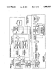
- FIG. 1 is a block diagram of the hardware control loop in accordance with a preferred embodiment of the present invention
- FIG. 2 is a functional block diagram of the software control loop in accordance with a preferred embodiment of the present invention.
- FIG. 3 is a flow chart of the precalculation summary in accordance with a preferred embodiment of the present invention.
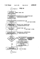
- FIG. 4 is a flow chart of the real time interrupt in accordance with a first preferred embodiment of the present invention.
- FIG. 5 is a flow chart of the real time interrupt in accordance with a second preferred embodiment of the present invention.
- FIGS. 6-10 are flow charts of the detailed precalculations shown in FIG. 3;
- FIG. 11 is a flow chart of the detailed real time interrupt shown in FIG. 4;
- FIGS. 12 and 13 are flow charts of the acceleration portion of the motion profile in accordance with the first preferred embodiment illustrated in FIG. 4;
- FIG. 14 is a flow chart of the acceleration portion of the motion profile in accordance with the second preferred embodiment illustrated in FIG. 5;
- FIG. 15 is a flow chart of the constant velocity portion of the motion profile
- FIGS. 16 and 17 are flow charts of the deceleration portion of the motion profile in accordance with the first preferred embodiment illustrated in FIG. 4;
- FIG. 18 is a flow chart of the deceleration portion of the motion profile in accordance with the second preferred embodiment illustrated in FIG. 5;
- FIG. 19 is a flow chart of the interconnected tail portion of the motion profile
- FIGS. 20 and 21 are flow charts of the target zone
- FIG. 22 shows a position error calculation subroutine in accordance with a preferred embodiment of the present invention
- FIG. 23-26 show software code for the profile generator model in Quick BasicTM (Microsoft Corp.).
- the present invention is directed to a system for generating a motion control profile for advance motion control of a high performance servo axis, for use, for example, in chip placement systems for placing components on printed circuit boards, such as the Omniplace BTM manufactured by Universal Instrument Corporation of Binghamton, N.Y.
- the system in accordance with the present invention is shown in FIG. 1 and generally designated 10. Throughout the Figures, like numerals are used to represent like elements.
- Advanced motion control system 10 includes a controller 12 having multi-axis outputs 15 and multi-axis inputs 17, and a servo amplifier 14 which drives a motor 32 which, in turn, drives a load 34.
- a velocity feedback loop 25 is provided from motor 32 via a tachometer 30.
- a position feedback loop 35 is provided from load 34 via a position feedback device 36.
- Controller 12 comprises a multi-axis motion control processor 16, a digital to analog converter 20 and a feedback signal converter 18.
- Digital to analog converter 20 and feedback signal converter 18 communicate with multi-axis motion control processor 16 via high speed buss 22.
- Feedback signal converter 18 inputs multi-axis inputs 17 and position feedback loop 35.
- Digital to analog converter 20 outputs multi-axis outputs 15 and position error signal 19.
- Servo amplifier 14 comprises a first comparator 24 for determining velocity error, a second comparator 26 for determining current error, and a power amp 28.
- the first comparator 24 compares position error signal 19 the velocity feedback loop 25 and outputs a velocity error signal 21 reflective of the comparison.
- Velocity error signal 21 is compared with current feedback loop 25 by the second comparator 26 which in turn outputs a current error signal 23.
- the output of power amp 28 is used to drive the motor 32.
- FIG. 2 is a functional block diagram of the software embodiment illustrated in FIG. 1.
- the plant 64 represents the device to be driven or controlled.
- the input of the plant 64 is controlled by profile/target zone switch 63 having two possible positions.
- the switch 63 is in a first position 63a, the plant 64 is in communication with a profile circuit 41.
- the switch 63 is controlled by profile/target zone switch control 40.
- Profile circuit 41 includes a motion profile position generator 38 which communicates with the profile/target zone switch control 40.
- Velocity reference output 55 is applied to a feedforward gain generator 60 and reference position output 55a is applied to a comparator 56.
- the comparator 56 compares the position reference output 55A and a position feedback signal 35, described previously with reference to FIG. 1, and produces a position error output 57 which is applied to a first proportional gain generator 58.
- Outputs from the first proportional gain generator 58 and the feedforward gain generator 60 are applied to a first summation device 62.
- the output of the first summation device is applied to position 63a of profile/target zone switch 63.
- the target zone circuit 43 includes a target zone position generator 42 which communicates with profile/target zone switch control 40 and which produces an output which is applied to a deadband adjuster 44.
- the deadband adjuster 44 correspondingly outputs an adjusted target position signal 45 which is applied to a fourth comparator 46 along with the position feedback signal 35.
- the output of the fourth comparator 46, position error signal 47, is applied to second proportional gain generator 48 and to integration time constant error generator 50.
- the outputs of generator 48 and generator 50 are applied to a second summation device 52, and the corresponding output is applied to error limit adjust 54.
- Error limit adjust 54 produces an output, target position error signal 53, which is applied to position 63b of profile/target zone switch 63.
- the profile circuit 41 provides the digital motion reference for point to point movement.
- the known input parameters are acceleration/deceleration rate, total distance movement, and maximum velocity.
- the software profile generator first precalculates the maximum velocity achieved based on the total point to point distance and programmed acceleration rate. If the total distance is greater than the distance to accelerate to constant velocity and decelerate from constant velocity then the motion profile is trapezoidal. If the peak velocity is found to be less than the constant velocity for the total move distance then the motion profile is triangular. The s-curve is derived from the trapezoid or triangle profile.
- the software When the peak velocity obtained is less than the constant velocity and the profile type selected is trapezoidal the software performs a compensation reduction based on a percentage of the peak velocity.
- the compensation transforms a triangular profile into a trapezoidal profile.
- the tuning parameter that controls the magnitude of peak velocity reduction is called tip compensation. This reduces the "jerk" forces produced when acceleration changes to deceleration at the peak velocity or tip of the velocity-time profile.
- the real time interrupt is shown in FIG. 11.
- the motion control system of the present invention utilizes either of two preferred motion profiles, a trapezoid or s-curve velocity time profile.
- the precalculation permits selection of either the trapezoid or the s-curve velocity-time profile before any point to point move.
- the trapezoid profile real time calculations are summarized in FIGS. 5 and shown in detail in FIGS. 14, 15 and 18. During each one millisecond time interval the acceleration increment is added to the previous velocity sum. The distance is calculated by adding the velocity sum to the previous distance sum.
- the s-curve profile real time calculations are summarized in FIG. 4 and shown in detail in FIGS. 12, 13 and 15-17.
- the acceleration increment is added to the previous acceleration sum for one-half the acceleration time.
- the acceleration increment is subtracted from the previous acceleration sum.
- the acceleration sum is added to the previous velocity sum.
- the distance is calculated by adding the velocity sum to the previous distance sum. ##EQU1##
- the acceleration increment is added to the previous acceleration sum for one-half the acceleration time.
- the acceleration increment is subtracted from the previous acceleration sum.
- the acceleration sum is subtracted from the previous velocity sum.
- the distance is calculated by adding the velocity sum to the previous distance sum. ##EQU2##
- the software signals the changes required to switch into the target zone mode, as shown in FIG. 19.
- the interconnect zone illustrated in this figure provides a continuous velocity between the end of the reference profile and the target zone. If the magnitude of the position follow error is greater than the target zone gain limit, the system continues to control the loop from the main profile (which has finished and therefore the reference remains the target position). When the magnitude of the velocity error is equal to or less than the target zone gain limit, the system then switches to the target zone control loop. In this way, the system eases into the target zone control loop without creating jerk forces.
- the processor does a complete position feedback calculation.
- the first calculation computes the position difference between the profile reference position and the actual encoder feedback position. This value is called the position following error.
- the position error calculation subroutine is shown in FIG. 22.
- the position following error is multiplied by a programmable proportional gain parameter, scaled and sent out to the servo amplifier as a position error signal. This is in effect until the axis reaches the target zone.
- position error is accumulated (integrated), as shown in FIGS. 20 and 21.
- This allows the software to compensate for static disturbances that would otherwise keep the position error from becoming zero when the axis has stopped moving.
- static disturbances include friction, springs, windup, and gravitational forces.
- the gain is determined by the target zone proportional gain parameter and the integration time constant parameter.
- the torque is then range limited by the target zone gain limit parameter and sent out to the servo amplifier.
- the deadband window parameter determines the lock on target zone. If the deadband window is set to zero then the axis will lock on target within + or - one half an encoder count.
- the software is also capable of providing velocity feedforward compensation. This is accomplished in software by precomputing the reference command velocity and adding this quantity, scaled by the feedforward gain parameter to the position error signal. This will reduce the intrinsic following error or lagging position error.
- Tuning parameters allow a wide range of adjustments to satisfy all requirements of servo system performance.
- the velocity parameter determines the maximum slew velocity the axis travels toward its target position.
- the axis travels at this constant velocity until it must begin to decelerate in order to stop near the target position. This parameter is in effect outside the target zone.
- This parameter determines the acceleration rate at which the axis begins its move toward the target position.
- the axis accelerates at this constant rate until it reaches the slew velocity or it must begin deceleration to stop near the target position. Deceleration is equal to the acceleration rate.
- This parameter is in effect outside the target zone.
- This proportional gain parameter determines the amount of gain applied to the position error signal. Adjustment of this parameter controls the smoothness or stiffness of the actual servo motor motion profile. This parameter is in effect outside the target zone.
- the feed forward gain parameter determines the amount of precomputed reference command velocity added to the position error. Adjustment of this parameter controls the amount of lag in the actual position versus the reference generator profile position This parameter aids adjustment of the control loop if the mechanical system does not allow sufficient proportional gain amounts due to instabilities and compliance. This parameter is in effect outside the target zone.
- the tip compensation parameter determines the amount of peak velocity removed when the motion profile is triangular. This reduces the "jerk” force produced when acceleration changes to deceleration at the midpoint of the incremental move. This parameter is in effect outside the target zone.
- the target zone gain parameter determines the amount of proportional gain applied to the position error signal.
- the target zone mode is latched when the profile generator command has completed the trajectory and remains latched until a new destination is commanded. This parameter is in effect only when the system enters the target zone.
- the integration time constant determines the speed of applied signal gain added to the proportion gain whenever the position error is not equal to the target window.
- the integration signal gain is fixed at 2.5 millivolts. This parameter is only in effect when the system enters the target zone.
- the target zone gain limit parameter determines the maximum amount of gain applied by proportional gain and integration gain. This "clamps" the error signal preventing instability if a large error exists or an error exists for a large amount of time. This parameter is only in effect when the system enters the target zone.
- This value defines a distance in encoder error counts which extends in both directions from the target position. When the axis is within this distance of target position the system is considered to be "in-position" and settled.
- the proportional gain value is equal to zero and the integration gain value is held constant to the value of applied gain needed to enter the dead band window.
- the goal of every closed-loop servo system is to position to the greatest accuracy possible utilizing the full resolution of the encoder feedback system.
- mechanical backlash is present between the encoder feedback location and the servo motor drive shaft. This is a conditionally unstable system and the target dead band window has to be adjusted to a value greater than the mechanical backlash angle thus preventing oscillation around the target zone.
- This parameter determines the maximum allowable position error allowed outside the target zone.
- the actual position is compared with the reference profile generator position at one millisecond intervals. If the magnitude of the position error exceeds the preprogram position following error parameter the axis executes an error shut down forcing the servo motor to a complete stop with full electrical braking power. This parameter is in effect outside the target zone.
- FIGS. 23-26 show the software code for a preferred position profile generator model algorithm in Quick BasicTM. Of course, any suitable program could be used.
Abstract
Description
Velocity(t)=Velocity(t-1)+Acceleration
Distance(t)=Distance(t-1)+Velocity(t)
Velocity(t)=Constant velocity
Velocity(t)=Tip compensated constant velocity
Distance(t)=Distance(t-1)+Velocity(t)
Velocity(t)=Velocity(t-1)-Acceleration
Distance(t)=Distance(t-1)+Velocity(t)
Velocity(t)=Constant velocity
Distance(t)=Distance(t-1)+Velocity(t)
Position error signal=(proportional gain * follow error)/256
Position error signal=(proportional gain * error counts)/16+integral gain
Velocity feedforward=(feedforward gain * velocity)/256
Claims (11)
Priority Applications (1)
| Application Number | Priority Date | Filing Date | Title |
|---|---|---|---|
| US07/356,372 US4988935A (en) | 1989-05-24 | 1989-05-24 | Advanced digital motion control |
Applications Claiming Priority (1)
| Application Number | Priority Date | Filing Date | Title |
|---|---|---|---|
| US07/356,372 US4988935A (en) | 1989-05-24 | 1989-05-24 | Advanced digital motion control |
Publications (1)
| Publication Number | Publication Date |
|---|---|
| US4988935A true US4988935A (en) | 1991-01-29 |
Family
ID=23401197
Family Applications (1)
| Application Number | Title | Priority Date | Filing Date |
|---|---|---|---|
| US07/356,372 Expired - Lifetime US4988935A (en) | 1989-05-24 | 1989-05-24 | Advanced digital motion control |
Country Status (1)
| Country | Link |
|---|---|
| US (1) | US4988935A (en) |
Cited By (47)
| Publication number | Priority date | Publication date | Assignee | Title |
|---|---|---|---|---|
| US5105135A (en) * | 1989-11-08 | 1992-04-14 | Okuma Machinery Works Ltd. | Feedback controller for NC controlled machine tools |
| US5159254A (en) * | 1990-04-09 | 1992-10-27 | Mitsubishi Denki K.K. | Numerical control unit for estimating movement parameters using a model |
| US5221884A (en) * | 1989-12-11 | 1993-06-22 | Mitsubishi Denki K.K. | Numerical control apparatus |
| EP0691009A1 (en) * | 1993-03-15 | 1996-01-10 | Pentek, Inc. | System for positioning a workpoint |
| US5495158A (en) * | 1994-09-30 | 1996-02-27 | Allen-Bradley Company, Inc. | Apparatus and method used with AC motors for controlling motor operation |
| EP0740237A2 (en) * | 1991-09-02 | 1996-10-30 | Mitsubishi Denki Kabushiki Kaisha | Numerical control unit |
| US5644486A (en) * | 1994-10-24 | 1997-07-01 | Pitney Bowes Inc. | Programmable controller for mechanical systems |
| WO1997027624A1 (en) * | 1996-01-24 | 1997-07-31 | Cornell Research Foundation, Inc. | Pressurized underfill encapsulation of integrated circuits |
| US5684375A (en) * | 1995-06-20 | 1997-11-04 | Allen-Bradley Company, Inc. | Method and apparatus for tuning a motion control system |
| FR2752308A1 (en) * | 1996-08-09 | 1998-02-13 | Emhart Glass Mach Invest | SERVO MOTOR CONTROL |
| US5770829A (en) * | 1997-06-09 | 1998-06-23 | Seiberco Incorporated | General purpose position control system having recursive profile generator |
| US5821724A (en) * | 1995-02-03 | 1998-10-13 | Cms Gilbreth Packaging Systems | Feedback limiter for closed loop motor controller |
| US5886491A (en) * | 1995-09-29 | 1999-03-23 | Mitsubishi Denki Kabushiki Kaisha | Position control unit for electric motor |
| US6011376A (en) * | 1998-03-13 | 2000-01-04 | Cincinnati Milacron Inc. | Method and apparatus for injection molding machine control |
| US6107769A (en) * | 1998-12-29 | 2000-08-22 | Schneider Automation Inc. | Positional-based motion controller with a bias latch |
| US6198246B1 (en) | 1999-08-19 | 2001-03-06 | Siemens Energy & Automation, Inc. | Method and apparatus for tuning control system parameters |
| EP1097889A2 (en) * | 1999-11-08 | 2001-05-09 | Pitney Bowes Inc. | Motion control methodology for a high-speed inserting machine or other mailing apparatus |
| US6286055B1 (en) * | 1996-11-07 | 2001-09-04 | Okuma Corporation | Error correction apparatus for NC machine tool |
| US6470225B1 (en) | 1999-04-16 | 2002-10-22 | Siemens Energy & Automation, Inc. | Method and apparatus for automatically tuning feedforward parameters |
| US20020156541A1 (en) * | 1999-04-16 | 2002-10-24 | Yutkowitz Stephen J. | Method and apparatus for tuning compensation parameters |
| US6477433B1 (en) * | 1998-06-04 | 2002-11-05 | Honeywell International Inc. | Control of velocity limited systems |
| US20020172511A1 (en) * | 2001-05-17 | 2002-11-21 | Canon Kabushiki Kaisha | Method and apparatus for controlling motor |
| US20020172510A1 (en) * | 2001-05-17 | 2002-11-21 | Canon Kabushiki Kaisha | Method and apparatus for controlling motor |
| US20030033105A1 (en) * | 2001-04-26 | 2003-02-13 | Yutkowitz Stephen J. | Method and apparatus for self-calibrating a motion control system |
| US20030036868A1 (en) * | 2001-04-26 | 2003-02-20 | Yutkowitz Stephen J. | Method and apparatus for tuning compensation parameters in a motion control system associated with a mechanical member |
| US20030056147A1 (en) * | 1999-04-16 | 2003-03-20 | Yutkowitz Stephen J. | Method and apparatus for determining calibration options in a motion control system |
| US6639375B2 (en) * | 2001-10-30 | 2003-10-28 | Harold Beck And Sons, Inc. | Control device and method for controlling a control element |
| WO2004088439A1 (en) * | 2003-03-31 | 2004-10-14 | Henkel Kommanditgesellschaft Auf Aktien | Method for the computer-assisted regulating of a plurality of serially coupled machines, regulating device, and machine arrangement |
| US20040239281A1 (en) * | 2003-05-30 | 2004-12-02 | Bertsch Robert P. | System and method for conditioning a signal |
| US6876168B1 (en) * | 1999-05-20 | 2005-04-05 | National University Of Singapore | Disturbance attenuation in a precision servomechanism by a frequency-separated acceleration soft sensor |
| US20050162111A1 (en) * | 2002-04-05 | 2005-07-28 | Kazuhiko Tsutsui | Motor control device |
| US20050222741A1 (en) * | 2004-04-02 | 2005-10-06 | Tsung-Hsin Cheng | S-type smooth command generating method and means thereof |
| US20060024113A1 (en) * | 2004-07-28 | 2006-02-02 | Canon Kabushiki Kaisha | Conveying apparatus and recording apparatus having the same |
| US20060100723A1 (en) * | 2004-10-29 | 2006-05-11 | Dynacity Technology (Hk) Limited | Modular multi-axis motion control and driving system and method thereof |
| CN1310415C (en) * | 2004-09-23 | 2007-04-11 | 深圳市丰盛泰实业有限公司 | Multiple mani shaft synchronous control system for asynchronous motor |
| US20080091295A1 (en) * | 2002-02-21 | 2008-04-17 | Corey Gary J | CNC machine tool and integrated machine tool controller incorporating 3D and up to 8-axes real time interactive tool compensation |
| EP2068217A1 (en) | 2007-12-04 | 2009-06-10 | Pitney Bowes, Inc. | Method for controlling a DC motor |
| WO2009156069A1 (en) * | 2008-06-24 | 2009-12-30 | Technische Universität Carolo Wilhelmina Zu Braunschweig | Position-controlled mechanism and method for controlling mechanisms having several degrees of freedom of movement |
| US20110089928A1 (en) * | 2009-10-15 | 2011-04-21 | Temic Automotive Of North America, Inc. | Digitally controlling a power converter |
| US20130173046A1 (en) * | 2010-10-27 | 2013-07-04 | Makino Milling Machine Co., Ltd. | Correction Method at Time of Feed Axis Reversal |
| US20160363924A1 (en) * | 2015-06-12 | 2016-12-15 | Fanuc Corporation | Servo motor stop controller to control and stop servo motor during emergency stop |
| US20170146974A1 (en) * | 2015-11-20 | 2017-05-25 | Fanuc Corporation | Servo control device |
| CN109976300A (en) * | 2017-12-28 | 2019-07-05 | 上海铼钠克数控科技股份有限公司 | The performance indicator detection method and computer storage medium of servo-system |
| US10491142B2 (en) * | 2015-07-02 | 2019-11-26 | Fuji Corporation | Servomotor drive device |
| US20200293026A1 (en) * | 2019-03-14 | 2020-09-17 | Fanuc Corporation | Numerical control system of industrial machine |
| CN114637256A (en) * | 2022-02-22 | 2022-06-17 | 无锡先导智能装备股份有限公司 | Fly-cutting control method, device and system, electronic equipment and storage medium |
| CN116500889A (en) * | 2023-06-27 | 2023-07-28 | 广东技术师范大学 | Servo motor position precise control method and device based on space-time two-dimensional optimization |
Citations (2)
| Publication number | Priority date | Publication date | Assignee | Title |
|---|---|---|---|---|
| US4533991A (en) * | 1982-12-29 | 1985-08-06 | Storage Technology Corporation | Adaptive feedforward servo system |
| US4829219A (en) * | 1986-11-20 | 1989-05-09 | Unimation Inc. | Multiaxis robot having improved motion control through variable acceleration/deceleration profiling |
-
1989
- 1989-05-24 US US07/356,372 patent/US4988935A/en not_active Expired - Lifetime
Patent Citations (2)
| Publication number | Priority date | Publication date | Assignee | Title |
|---|---|---|---|---|
| US4533991A (en) * | 1982-12-29 | 1985-08-06 | Storage Technology Corporation | Adaptive feedforward servo system |
| US4829219A (en) * | 1986-11-20 | 1989-05-09 | Unimation Inc. | Multiaxis robot having improved motion control through variable acceleration/deceleration profiling |
Cited By (81)
| Publication number | Priority date | Publication date | Assignee | Title |
|---|---|---|---|---|
| US5105135A (en) * | 1989-11-08 | 1992-04-14 | Okuma Machinery Works Ltd. | Feedback controller for NC controlled machine tools |
| US5221884A (en) * | 1989-12-11 | 1993-06-22 | Mitsubishi Denki K.K. | Numerical control apparatus |
| US5159254A (en) * | 1990-04-09 | 1992-10-27 | Mitsubishi Denki K.K. | Numerical control unit for estimating movement parameters using a model |
| EP0740237A2 (en) * | 1991-09-02 | 1996-10-30 | Mitsubishi Denki Kabushiki Kaisha | Numerical control unit |
| EP0740237A3 (en) * | 1991-09-02 | 1996-12-04 | Mitsubishi Electric Corp | |
| EP0691009A4 (en) * | 1993-03-15 | 1998-05-20 | Pentek Inc | System for positioning a workpoint |
| EP0691009A1 (en) * | 1993-03-15 | 1996-01-10 | Pentek, Inc. | System for positioning a workpoint |
| US5495158A (en) * | 1994-09-30 | 1996-02-27 | Allen-Bradley Company, Inc. | Apparatus and method used with AC motors for controlling motor operation |
| US5644486A (en) * | 1994-10-24 | 1997-07-01 | Pitney Bowes Inc. | Programmable controller for mechanical systems |
| US5821724A (en) * | 1995-02-03 | 1998-10-13 | Cms Gilbreth Packaging Systems | Feedback limiter for closed loop motor controller |
| US5684375A (en) * | 1995-06-20 | 1997-11-04 | Allen-Bradley Company, Inc. | Method and apparatus for tuning a motion control system |
| US5886491A (en) * | 1995-09-29 | 1999-03-23 | Mitsubishi Denki Kabushiki Kaisha | Position control unit for electric motor |
| EP0865665A1 (en) * | 1996-01-24 | 1998-09-23 | Cornell Research Foundation, Inc. | Pressurized underfill encapsulation of integrated circuits |
| WO1997027624A1 (en) * | 1996-01-24 | 1997-07-31 | Cornell Research Foundation, Inc. | Pressurized underfill encapsulation of integrated circuits |
| EP0865665A4 (en) * | 1996-01-24 | 1999-01-07 | Cornell Res Foundation Inc | Pressurized underfill encapsulation of integrated circuits |
| FR2752308A1 (en) * | 1996-08-09 | 1998-02-13 | Emhart Glass Mach Invest | SERVO MOTOR CONTROL |
| US6286055B1 (en) * | 1996-11-07 | 2001-09-04 | Okuma Corporation | Error correction apparatus for NC machine tool |
| US5770829A (en) * | 1997-06-09 | 1998-06-23 | Seiberco Incorporated | General purpose position control system having recursive profile generator |
| US6011376A (en) * | 1998-03-13 | 2000-01-04 | Cincinnati Milacron Inc. | Method and apparatus for injection molding machine control |
| US6477433B1 (en) * | 1998-06-04 | 2002-11-05 | Honeywell International Inc. | Control of velocity limited systems |
| US6107769A (en) * | 1998-12-29 | 2000-08-22 | Schneider Automation Inc. | Positional-based motion controller with a bias latch |
| US6470225B1 (en) | 1999-04-16 | 2002-10-22 | Siemens Energy & Automation, Inc. | Method and apparatus for automatically tuning feedforward parameters |
| US20020156541A1 (en) * | 1999-04-16 | 2002-10-24 | Yutkowitz Stephen J. | Method and apparatus for tuning compensation parameters |
| US6961628B2 (en) * | 1999-04-16 | 2005-11-01 | Siemens Energy & Automation, Inc. | Method and apparatus for tuning compensation parameters |
| US6850806B2 (en) | 1999-04-16 | 2005-02-01 | Siemens Energy & Automation, Inc. | Method and apparatus for determining calibration options in a motion control system |
| US20030056147A1 (en) * | 1999-04-16 | 2003-03-20 | Yutkowitz Stephen J. | Method and apparatus for determining calibration options in a motion control system |
| US6876168B1 (en) * | 1999-05-20 | 2005-04-05 | National University Of Singapore | Disturbance attenuation in a precision servomechanism by a frequency-separated acceleration soft sensor |
| US6198246B1 (en) | 1999-08-19 | 2001-03-06 | Siemens Energy & Automation, Inc. | Method and apparatus for tuning control system parameters |
| EP1097889A2 (en) * | 1999-11-08 | 2001-05-09 | Pitney Bowes Inc. | Motion control methodology for a high-speed inserting machine or other mailing apparatus |
| US6301522B1 (en) * | 1999-11-08 | 2001-10-09 | Pitney Bowes Inc. | Motion control methodology for a high-speed inserting machine or other mailing apparatus |
| EP1097889A3 (en) * | 1999-11-08 | 2003-05-14 | Pitney Bowes Inc. | Motion control methodology for a high-speed inserting machine or other mailing apparatus |
| US6859747B2 (en) * | 2001-04-26 | 2005-02-22 | Siemens Energy & Automation, Inc. | Method and apparatus for self-calibrating a motion control system |
| US20040193385A1 (en) * | 2001-04-26 | 2004-09-30 | Yutkowitz Stephen J. | Method and apparatus for tuning compensation parameters in a motion control system associated with a mechanical member |
| US6920408B2 (en) | 2001-04-26 | 2005-07-19 | Siemens Energy & Automation, Inc. | Method and apparatus for tuning compensation parameters in a motion control system associated with a mechanical member |
| US20030036868A1 (en) * | 2001-04-26 | 2003-02-20 | Yutkowitz Stephen J. | Method and apparatus for tuning compensation parameters in a motion control system associated with a mechanical member |
| US20030033105A1 (en) * | 2001-04-26 | 2003-02-13 | Yutkowitz Stephen J. | Method and apparatus for self-calibrating a motion control system |
| US6865499B2 (en) * | 2001-04-26 | 2005-03-08 | Siemens Energy & Automation, Inc. | Method and apparatus for tuning compensation parameters in a motion control system associated with a mechanical member |
| US20020172510A1 (en) * | 2001-05-17 | 2002-11-21 | Canon Kabushiki Kaisha | Method and apparatus for controlling motor |
| US20020172511A1 (en) * | 2001-05-17 | 2002-11-21 | Canon Kabushiki Kaisha | Method and apparatus for controlling motor |
| US6823132B2 (en) | 2001-05-17 | 2004-11-23 | Canon Kabushiki Kaisha | Method and apparatus for controlling motor |
| US6838855B2 (en) * | 2001-05-17 | 2005-01-04 | Canon Kabushiki Kaisha | Method and apparatus for controlling motor |
| US6639375B2 (en) * | 2001-10-30 | 2003-10-28 | Harold Beck And Sons, Inc. | Control device and method for controlling a control element |
| US7853351B2 (en) * | 2002-02-21 | 2010-12-14 | Gary John Corey | CNC machine tool and integrated machine tool controller incorporating 3D and up to 8-axes real time interactive tool compensation |
| US20080091295A1 (en) * | 2002-02-21 | 2008-04-17 | Corey Gary J | CNC machine tool and integrated machine tool controller incorporating 3D and up to 8-axes real time interactive tool compensation |
| US20050162111A1 (en) * | 2002-04-05 | 2005-07-28 | Kazuhiko Tsutsui | Motor control device |
| US7068002B2 (en) * | 2002-04-05 | 2006-06-27 | Mitsubishi Denki Kabushiki Kaisha | Motor control device |
| WO2004088439A1 (en) * | 2003-03-31 | 2004-10-14 | Henkel Kommanditgesellschaft Auf Aktien | Method for the computer-assisted regulating of a plurality of serially coupled machines, regulating device, and machine arrangement |
| US7136719B2 (en) | 2003-03-31 | 2006-11-14 | Henkel Kommanditgesellschaft Auf Aktien | Method for the computer-assisted regulating of a plurality of serially coupled machines, regulating device and machine arrangement |
| US20060058896A1 (en) * | 2003-03-31 | 2006-03-16 | Sascha Pokorny | Method for the computer-assisted regulating of a plurality of serially coupled machines, regulating device and machine arrangement |
| US20050206337A1 (en) * | 2003-05-30 | 2005-09-22 | Bertsch Robert P | System and method for conditioning a signal |
| US7078872B2 (en) * | 2003-05-30 | 2006-07-18 | Caterpillar Inc | System and method for conditioning a signal |
| US20040239281A1 (en) * | 2003-05-30 | 2004-12-02 | Bertsch Robert P. | System and method for conditioning a signal |
| US7280899B2 (en) * | 2004-04-02 | 2007-10-09 | Delta Electronics, Inc. | S-type smooth command generating method and means thereof |
| US20050222741A1 (en) * | 2004-04-02 | 2005-10-06 | Tsung-Hsin Cheng | S-type smooth command generating method and means thereof |
| US20060024113A1 (en) * | 2004-07-28 | 2006-02-02 | Canon Kabushiki Kaisha | Conveying apparatus and recording apparatus having the same |
| US7415239B2 (en) * | 2004-07-28 | 2008-08-19 | Canon Kabushiki Kaisha | Conveying apparatus and recording apparatus having the same |
| CN1310415C (en) * | 2004-09-23 | 2007-04-11 | 深圳市丰盛泰实业有限公司 | Multiple mani shaft synchronous control system for asynchronous motor |
| US20060100723A1 (en) * | 2004-10-29 | 2006-05-11 | Dynacity Technology (Hk) Limited | Modular multi-axis motion control and driving system and method thereof |
| US7194321B2 (en) * | 2004-10-29 | 2007-03-20 | Dynacity Technology (Hk) Limited | Modular multi-axis motion control and driving system and method thereof |
| EP2068217A1 (en) | 2007-12-04 | 2009-06-10 | Pitney Bowes, Inc. | Method for controlling a DC motor |
| US7898207B2 (en) | 2007-12-04 | 2011-03-01 | Pitney Bowes Inc. | Method for controlling a DC motor |
| WO2009156069A1 (en) * | 2008-06-24 | 2009-12-30 | Technische Universität Carolo Wilhelmina Zu Braunschweig | Position-controlled mechanism and method for controlling mechanisms having several degrees of freedom of movement |
| US8624570B2 (en) | 2009-10-15 | 2014-01-07 | Continental Automotive Systems, Inc. | Digitally controlling a power converter |
| US20110089928A1 (en) * | 2009-10-15 | 2011-04-21 | Temic Automotive Of North America, Inc. | Digitally controlling a power converter |
| US9588509B2 (en) * | 2010-10-27 | 2017-03-07 | Makino Milling Machine Co., Ltd. | Correction method at time of feed axis reversal |
| US20130173046A1 (en) * | 2010-10-27 | 2013-07-04 | Makino Milling Machine Co., Ltd. | Correction Method at Time of Feed Axis Reversal |
| DE102016110370B4 (en) * | 2015-06-12 | 2019-07-04 | Fanuc Corporation | SERVO MOTOR STOP CONTROL TO CONTROL AND STOP A SERVO MOTOR DURING AN EMERGENCY STOP |
| US20160363924A1 (en) * | 2015-06-12 | 2016-12-15 | Fanuc Corporation | Servo motor stop controller to control and stop servo motor during emergency stop |
| EP3319226B1 (en) * | 2015-07-02 | 2021-04-28 | FUJI Corporation | Servomotor drive device |
| US10491142B2 (en) * | 2015-07-02 | 2019-11-26 | Fuji Corporation | Servomotor drive device |
| US20170146974A1 (en) * | 2015-11-20 | 2017-05-25 | Fanuc Corporation | Servo control device |
| US10228676B2 (en) * | 2015-11-20 | 2019-03-12 | Fanuc Corporation | Servo control device |
| CN106774445B (en) * | 2015-11-20 | 2020-01-17 | 发那科株式会社 | Servo control device |
| CN106774445A (en) * | 2015-11-20 | 2017-05-31 | 发那科株式会社 | Servocontrol device |
| CN109976300A (en) * | 2017-12-28 | 2019-07-05 | 上海铼钠克数控科技股份有限公司 | The performance indicator detection method and computer storage medium of servo-system |
| US20200293026A1 (en) * | 2019-03-14 | 2020-09-17 | Fanuc Corporation | Numerical control system of industrial machine |
| US11531323B2 (en) * | 2019-03-14 | 2022-12-20 | Fanuc Corporation | Numerical control system of industrial machine |
| CN114637256A (en) * | 2022-02-22 | 2022-06-17 | 无锡先导智能装备股份有限公司 | Fly-cutting control method, device and system, electronic equipment and storage medium |
| CN114637256B (en) * | 2022-02-22 | 2023-07-14 | 无锡先导智能装备股份有限公司 | Fly-cutting control method, device and system, electronic equipment and storage medium |
| CN116500889A (en) * | 2023-06-27 | 2023-07-28 | 广东技术师范大学 | Servo motor position precise control method and device based on space-time two-dimensional optimization |
| CN116500889B (en) * | 2023-06-27 | 2023-10-03 | 广东技术师范大学 | Servo motor position precise control method and device based on space-time two-dimensional optimization |
Similar Documents
| Publication | Publication Date | Title |
|---|---|---|
| US4988935A (en) | Advanced digital motion control | |
| US4727303A (en) | Positional control method and system utilizing same | |
| US5331264A (en) | Method and device for generating an input command for a motion control system | |
| EP0417312B1 (en) | Feedforward control unit for servomotor | |
| US5159254A (en) | Numerical control unit for estimating movement parameters using a model | |
| US5134354A (en) | Servo motor control apparatus | |
| US5684374A (en) | Method and apparatus for tuning a motion control system having an external velocity loop | |
| EP1143316A1 (en) | Nc machine tool, and method of controlling nc machine tool | |
| US5920169A (en) | Servomotor control method | |
| US5379367A (en) | Linear interpolating method for robot control | |
| EP0089156B1 (en) | Method and apparatus for controlling acceleration and/or deceleration | |
| US5073748A (en) | Method for limiting the rate-of-change of acceleration in numerical driving systems | |
| US5986422A (en) | Control mode changing over method for servo control system | |
| US4396975A (en) | Position control system for a closed loop type numerical-controlled machine tool | |
| EP0141860B1 (en) | Position-controlling apparatus | |
| EP0290618A1 (en) | Digital servo system | |
| US20050052149A1 (en) | Position controller of feed shaft | |
| US4553078A (en) | Servo control booster system for minimizing following error | |
| US4750104A (en) | Method of and apparatus for tracking position error control | |
| US4771389A (en) | Control method and unit for controlling a manipulator | |
| EP0287684B1 (en) | Negative feedback control system | |
| US4968923A (en) | Servo control system | |
| US5369568A (en) | Position controlling method of robot | |
| JP3460761B2 (en) | Robot control device | |
| JPH07110714A (en) | Method for controlling position, speed, and torque by plural motors |
Legal Events
| Date | Code | Title | Description |
|---|---|---|---|
| AS | Assignment |
Owner name: UNIVERSAL INSTRUMENTS CORPORATION, BINGHAMTON, NY, Free format text: ASSIGNMENT OF ASSIGNORS INTEREST.;ASSIGNOR:YORK, JAMES E.;REEL/FRAME:005085/0305 Effective date: 19890523 |
|
| STCF | Information on status: patent grant |
Free format text: PATENTED CASE |
|
| FPAY | Fee payment |
Year of fee payment: 4 |
|
| FEPP | Fee payment procedure |
Free format text: PAYOR NUMBER ASSIGNED (ORIGINAL EVENT CODE: ASPN); ENTITY STATUS OF PATENT OWNER: LARGE ENTITY |
|
| FPAY | Fee payment |
Year of fee payment: 8 |
|
| FPAY | Fee payment |
Year of fee payment: 12 |
|
| AS | Assignment |
Owner name: MORGAN STANLEY SENIOR FUNDING, INC., AS THE ADMINI Free format text: PATENT SECURITY AGREEMENT FIRST LIEN;ASSIGNOR:UNIVERSAL INSTRUMENTS CORPORATION;REEL/FRAME:018545/0555 Effective date: 20061103 |
|
| AS | Assignment |
Owner name: MORGAN STANLEY SENIOR FUNDING, INC., NEW YORK Free format text: PLEDGE AND SECURITY AGREEMENT (FIRST LIEN);ASSIGNOR:UI HOLDING CO.;REEL/FRAME:020270/0755 Effective date: 20061106 |
|
| AS | Assignment |
Owner name: PATRIARCH PARTNERS AGENCY SERVICES, LLC, AS THE AD Free format text: CHANGE OF ADMINISTRATIVE AGENT;ASSIGNOR:MORGAN STANLEY SENIOR FUNDING INC., AS THE ADMINISTRATIVE AGENT;REEL/FRAME:024640/0963 Effective date: 20081118 Owner name: PATRIARCH PARTNERS AGENCY SERVICES, LLC, AS THE AD Free format text: CHANGE OF ADMINISTRATIVE AGENT;ASSIGNOR:MORGAN STANLEY SENIOR FUNDING INC., AS THE ADMINISTRATIVE AGENT;REEL/FRAME:024640/0980 Effective date: 20081118 |