US4976012A - Method of forming a web - Google Patents
Method of forming a web Download PDFInfo
- Publication number
- US4976012A US4976012A US07/031,794 US3179487A US4976012A US 4976012 A US4976012 A US 4976012A US 3179487 A US3179487 A US 3179487A US 4976012 A US4976012 A US 4976012A
- Authority
- US
- United States
- Prior art keywords
- strand
- pins
- bed
- pattern
- web
- Prior art date
- Legal status (The legal status is an assumption and is not a legal conclusion. Google has not performed a legal analysis and makes no representation as to the accuracy of the status listed.)
- Expired - Lifetime
Links
Images


Classifications
-
- B—PERFORMING OPERATIONS; TRANSPORTING
- B29—WORKING OF PLASTICS; WORKING OF SUBSTANCES IN A PLASTIC STATE IN GENERAL
- B29C—SHAPING OR JOINING OF PLASTICS; SHAPING OF MATERIAL IN A PLASTIC STATE, NOT OTHERWISE PROVIDED FOR; AFTER-TREATMENT OF THE SHAPED PRODUCTS, e.g. REPAIRING
- B29C70/00—Shaping composites, i.e. plastics material comprising reinforcements, fillers or preformed parts, e.g. inserts
- B29C70/04—Shaping composites, i.e. plastics material comprising reinforcements, fillers or preformed parts, e.g. inserts comprising reinforcements only, e.g. self-reinforcing plastics
- B29C70/28—Shaping operations therefor
- B29C70/54—Component parts, details or accessories; Auxiliary operations, e.g. feeding or storage of prepregs or SMC after impregnation or during ageing
- B29C70/545—Perforating, cutting or machining during or after moulding
-
- B—PERFORMING OPERATIONS; TRANSPORTING
- B29—WORKING OF PLASTICS; WORKING OF SUBSTANCES IN A PLASTIC STATE IN GENERAL
- B29C—SHAPING OR JOINING OF PLASTICS; SHAPING OF MATERIAL IN A PLASTIC STATE, NOT OTHERWISE PROVIDED FOR; AFTER-TREATMENT OF THE SHAPED PRODUCTS, e.g. REPAIRING
- B29C70/00—Shaping composites, i.e. plastics material comprising reinforcements, fillers or preformed parts, e.g. inserts
- B29C70/04—Shaping composites, i.e. plastics material comprising reinforcements, fillers or preformed parts, e.g. inserts comprising reinforcements only, e.g. self-reinforcing plastics
- B29C70/06—Fibrous reinforcements only
- B29C70/10—Fibrous reinforcements only characterised by the structure of fibrous reinforcements, e.g. hollow fibres
- B29C70/16—Fibrous reinforcements only characterised by the structure of fibrous reinforcements, e.g. hollow fibres using fibres of substantial or continuous length
- B29C70/22—Fibrous reinforcements only characterised by the structure of fibrous reinforcements, e.g. hollow fibres using fibres of substantial or continuous length oriented in at least two directions forming a two dimensional structure
-
- B—PERFORMING OPERATIONS; TRANSPORTING
- B29—WORKING OF PLASTICS; WORKING OF SUBSTANCES IN A PLASTIC STATE IN GENERAL
- B29C—SHAPING OR JOINING OF PLASTICS; SHAPING OF MATERIAL IN A PLASTIC STATE, NOT OTHERWISE PROVIDED FOR; AFTER-TREATMENT OF THE SHAPED PRODUCTS, e.g. REPAIRING
- B29C70/00—Shaping composites, i.e. plastics material comprising reinforcements, fillers or preformed parts, e.g. inserts
- B29C70/04—Shaping composites, i.e. plastics material comprising reinforcements, fillers or preformed parts, e.g. inserts comprising reinforcements only, e.g. self-reinforcing plastics
- B29C70/28—Shaping operations therefor
- B29C70/30—Shaping by lay-up, i.e. applying fibres, tape or broadsheet on a mould, former or core; Shaping by spray-up, i.e. spraying of fibres on a mould, former or core
- B29C70/38—Automated lay-up, e.g. using robots, laying filaments according to predetermined patterns
- B29C70/382—Automated fiber placement [AFP]
-
- D—TEXTILES; PAPER
- D04—BRAIDING; LACE-MAKING; KNITTING; TRIMMINGS; NON-WOVEN FABRICS
- D04H—MAKING TEXTILE FABRICS, e.g. FROM FIBRES OR FILAMENTARY MATERIAL; FABRICS MADE BY SUCH PROCESSES OR APPARATUS, e.g. FELTS, NON-WOVEN FABRICS; COTTON-WOOL; WADDING ; NON-WOVEN FABRICS FROM STAPLE FIBRES, FILAMENTS OR YARNS, BONDED WITH AT LEAST ONE WEB-LIKE MATERIAL DURING THEIR CONSOLIDATION
- D04H3/00—Non-woven fabrics formed wholly or mainly of yarns or like filamentary material of substantial length
- D04H3/02—Non-woven fabrics formed wholly or mainly of yarns or like filamentary material of substantial length characterised by the method of forming fleeces or layers, e.g. reorientation of yarns or filaments
Definitions
- Plastic composites reinforced with fibers are known and used in a wide variety of aerospace, industrial and sporting applications. Initially, the reinforcing structures were woven fabrics which provided uniformity throughout the composite. However, nonwoven webs are now being used because they are less expensive than woven fabrics. Normally such webs have been laid down randomly or in a semi-ordered fashion. It is apparent that improved composites could be produced if the nonwoven web could be laid down in a precisely ordered fashion. In some composites, complete uniformity is desired, whereas, in others, the fiber density should be greater at the locations where the stresses are greater.
- a reinforcing web for a composite structure is prepared by first laying the end of a continuous strand in a bed of densely packed pins. After the end is located, the strand is deposited continuously beneath the tops of the pins by guiding it through the bed according to a desired pattern, while simultaneously pulling the strand from a package. When a complete web has been laid, the strand is cut and the web is transferred intact for further processing into a composite structure. In the guiding step, the strand is advanced in a pattern of repeating, closed geometrical shapes.
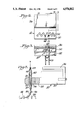
- FIG. 1 is a schematic illustration of an installation which has been used in the practice of the invention.
- FIG. 2 is a fragmentary, perspective enlargement of the web-forming apparatus shown in FIG. 1.
- FIGS. 3-5 are front, top and side views of the winding head shown in FIGS. 1 and 2, FIG. 5 having been taken on line 5--5 in FIG. 4.
- FIG. 6 shows fragments of a web formed with precise uniformity by the method of the present invention.
- FIGS. 7 and 8 are side and top views of a device for transferring a web from the bed of pins shown in FIGS. 1 and 2.
- FIG. 9 illustrates transfer of a web from the bed on which it was formed.
- FIG. 10 is a fragmentary, enlarged view of the bed shown in FIGS. 1, 2 and 7-9.
- FIG. 11 is a perspective view of a modification of the apparatus.
- FIG. 12 is a graphic representation of comparisons in energy absorptions between panels reinforced with webs prepared according to the present invention and others reinforced by fabrics and mats.
- FIGS. 13 and 14 show effects of impact tests of panels reinforced with fabrics and with the webs of the present invention.
- FIG. 1 an apparatus useful in the practice of the present invention is shown in association with other elements of a web-forming installation.
- a dispensing head 12 Through the arm of a robot 10, there is a dispensing head 12 through which a filamentary yarn 14 is pulled from a package 16 on a creel 18.
- Robot 10 functions as an automatic manipulator for moving head 12 relative to a densely packed bed 20 of deflectible pins according to a program set in a microprocessor within a controller 22.
- Other elements coupled to the controller are a CRT terminal 24, a direct current (dc) power supply 26 and a teach pendant or manual controller 28.
- yarn 14 is held by its engagement with pins in bed 20 and pulled from package 16 by the movement of head 12 in response to instructions from the programmed controller 22, i.e., according to the pattern desired for a given web.
- the robotized winding head 12 includes a block 30 having a step 32 provided with threaded passages 34 for one or more strand-guiding tubes 35.
- Block 30 is fastened to a bracket 36 which, in turn, is fastened to a mounting disc at the end of the arm on robot 10.
- Each tube 35 has a straight length that extends through a threaded housing 38 and terminates in a curved length or horn 40.
- the straight length is freely rotatable in spaced sleeve bearings 42 in housing 38 and is retained by collars 44, 45.
- Housing 38 is mounted in one of the threaded passages 34.
- horn 40 on tube 35 projects into the bed 20 of pins 50 and trails the straight length as head 12 is moved by robot 10.
- Horn 40 is free to move in either direction, depending on its location with respect to the pins it contacts.
- pins 50 are deflected as horn 40 moves through the bed. Due to the resilience of their mounting, the pins spring back toward a normally upright position and hold yarn 14 in the desired pattern.
- yarn 14 is anchored in the bed by frictional engagement with the pins and is pulled from package 16 by the programmed movement of dispensing head 12.
- Horn 40 dispenses yarn 14 beneath the tops of the pins 50 and also engages preceding loops to insure their placement at the desired depth in the bed 20.
- a web of the type shown in FIG. 6 is formed by programming the robot to move the head in a circular motion as it is advanced longitudinally through the length of the pattern. At the end of each row, the head is traversed laterally and advanced longitudinally in the reverse direction.
- the circular motion is a succession of orthogonal, linear steps but the yarn is deposited in a shingled series of in-line loops due to the manner in which pins 50 spring back toward their normal upright position.
- the robot could as well be programmed to move in other patterns of repeating, closed geometrical shapes such as squares or triangles.
- a transfer device 60 for removing a web from the bed of pins 50 is shown in FIGS. 7 and 8.
- Device 60 includes a plurality of spaced blades 62 attached at one end to a bar 64. The free ends of the blades 62 are held in alignment by a sliding bar 66 as they are inserted into the bed of pins beneath a formed web. Once passed beneath the web, the ends of blades 62 are retained in another bar 68.
- a second device 60 is located as shown in FIG. 9 and the assembly is then used to remove the web from the bed of pins.
- a binder resin is applied to insure the integrity of the web which can then be transferred to a suitable mold for fabrication of a composite structure.
- FIG. 10 Details of a base and retainer for the bed of pins 50 appear in FIG. 10 where it will be seen that the shanks of the pins project through holes 70 in an elastomeric sheet 72.
- the heads of the pins are embedded in a layer 74 of elastomeric adhesive which also serves to adhere sheet 72 to a retainer plate 76.
- a selected number of retainers is assembled and each is fastened to a base plate 78 by screws 80.
- the modification shown in FIG. 11 has a head 12' adapted for attachment to the arm of a robot.
- Head 12' includes a block 30' provided with an aperture 90 which receives a rotor 92, a belt 93 and a pulley 94.
- a motor 96 is coupled to the pulley 94 for driving rotor 92.
- a strand-guiding tube 35' is mounted eccentrically in rotor 92.
- the robot can be programmed to move head 12' linearly and the rotary movement of rotor 92 causes a shingled series of in-line loops to be deposited in the bed of pins.
- the curved horn on strand-guiding tube 35' pushes successive loops to the same level in each row, thus forming an ordered array of the type shown in FIG. 6.
- the illustrated apparatus is capable of precisely locating extra fibers at the needed locations to handle these localized stresses.
- strand is meant to denote a yarn of continuous filaments or a yarn spun from staple fibers. It also denotes such a yarn joined with another of the same or a different composition. In the latter respect, yarns of graphite, polyamide and polyester have been used to prepare webs.
- yarn 14 from a package 16 is threaded through a freely rotatable tube 35 and laid into the bed 20 of pins 50 manually.
- the head 12 is placed so that the curved length or horn 40 of tube 35 lies within the bed 20 below the tops of pins 50.
- head 12 including tube 35 is moved in a selected pattern through pins 50, pulling yarn 14 from package 16 and depositing it continuously in bed 20.
- Both the pins and horn 40 are deflected as the horn moves through bed 20.
- the strand is cut, a device 60 is used to remove the web intact, a binder resin is applied to insure its integrity and the web is laid up with additional plies. Then, the entire layup is impregnated with a resin, covered with a vacuum bag and pressed under suitable pressure and temperature conditions and for the requisite time to form an energy absorbing panel.
- the reinforcing web is fabricated from reinforcing fiber or yarn which is pre-impregnated or coated with a thermoplastic polymer matrix.
- the web is subsequently fused at a suitable temperature and pressure either as a single ply or as a layup of multiple plies, with or without the need for additional binder resin.
- the coated yarns may even be fused together during the lay down process.
- the reinforcing yarn may be pre-impregnated with a thermoset polymer matrix and subsequently cured with or without the need for additional binder resin.
- FIG. 12 Graphs showing improved impact resistances for panels A, B reinforced with webs made in accordance with the method of the present invention are shown in FIG. 12.
- the panels A and B were reinforced with loops of filamentary, 1140 denier Kevlar® 49 aramid fiber.
- Panel C was reinforced with plies of a plain weave fabric of the same yarn.
- Panel D was reinforced with a swirl mat of glass fibers. All of the panels were 50% polymer by weight and the polymer was an amorphous polyethylene terephthalate containing a glycol additive.
- FIGS. 13 and 14 Locations where panels reinforced with a fabric and with the looped webs of the present invention have been tested are represented in FIGS. 13 and 14, respectively.
- FIG. 13 it will be seen that a raised, impacted area is relatively small.
- the plunger used in the test not only penetrated the panel but also tore the fabrics in lines between the wales of the plain weave. Otherwise, there were no failures due to breakage or fibers pulled out of the matrix.
- FIG. 14 there is a larger area of interaction in which the loops pulled out of the matrix around the puncture. In turn, those loops pulled others out and the pull-out was progressive throughout the raised area of interaction.
Abstract
A method of preparing a reinforcing web for a composite structure. A continuous strand is deposited in a bed of pins according to a desired pattern such as overlapped rows of shingled loops.
Description
This is a continuation-in-part of my copending application Ser. No. 445,166, filed Nov. 29, 1982, now U.S. Pat. No. 4,715,924.
Plastic composites reinforced with fibers are known and used in a wide variety of aerospace, industrial and sporting applications. Initially, the reinforcing structures were woven fabrics which provided uniformity throughout the composite. However, nonwoven webs are now being used because they are less expensive than woven fabrics. Normally such webs have been laid down randomly or in a semi-ordered fashion. It is apparent that improved composites could be produced if the nonwoven web could be laid down in a precisely ordered fashion. In some composites, complete uniformity is desired, whereas, in others, the fiber density should be greater at the locations where the stresses are greater.
According to the method of the present invention, a reinforcing web for a composite structure is prepared by first laying the end of a continuous strand in a bed of densely packed pins. After the end is located, the strand is deposited continuously beneath the tops of the pins by guiding it through the bed according to a desired pattern, while simultaneously pulling the strand from a package. When a complete web has been laid, the strand is cut and the web is transferred intact for further processing into a composite structure. In the guiding step, the strand is advanced in a pattern of repeating, closed geometrical shapes.
FIG. 1 is a schematic illustration of an installation which has been used in the practice of the invention.
FIG. 2 is a fragmentary, perspective enlargement of the web-forming apparatus shown in FIG. 1.
FIGS. 3-5 are front, top and side views of the winding head shown in FIGS. 1 and 2, FIG. 5 having been taken on line 5--5 in FIG. 4.
FIG. 6 shows fragments of a web formed with precise uniformity by the method of the present invention.
FIGS. 7 and 8 are side and top views of a device for transferring a web from the bed of pins shown in FIGS. 1 and 2.
FIG. 9 illustrates transfer of a web from the bed on which it was formed.
FIG. 10 is a fragmentary, enlarged view of the bed shown in FIGS. 1, 2 and 7-9.
FIG. 11 is a perspective view of a modification of the apparatus.
FIG. 12 is a graphic representation of comparisons in energy absorptions between panels reinforced with webs prepared according to the present invention and others reinforced by fabrics and mats.
FIGS. 13 and 14 show effects of impact tests of panels reinforced with fabrics and with the webs of the present invention.
In FIG. 1, an apparatus useful in the practice of the present invention is shown in association with other elements of a web-forming installation. On the arm of a robot 10, there is a dispensing head 12 through which a filamentary yarn 14 is pulled from a package 16 on a creel 18. Robot 10 functions as an automatic manipulator for moving head 12 relative to a densely packed bed 20 of deflectible pins according to a program set in a microprocessor within a controller 22. Other elements coupled to the controller are a CRT terminal 24, a direct current (dc) power supply 26 and a teach pendant or manual controller 28. As will be explained more fully hereinafter, yarn 14 is held by its engagement with pins in bed 20 and pulled from package 16 by the movement of head 12 in response to instructions from the programmed controller 22, i.e., according to the pattern desired for a given web.
Referring to FIGS. 2-5, the robotized winding head 12 includes a block 30 having a step 32 provided with threaded passages 34 for one or more strand-guiding tubes 35. Block 30 is fastened to a bracket 36 which, in turn, is fastened to a mounting disc at the end of the arm on robot 10.
Each tube 35 has a straight length that extends through a threaded housing 38 and terminates in a curved length or horn 40. The straight length is freely rotatable in spaced sleeve bearings 42 in housing 38 and is retained by collars 44, 45. Housing 38 is mounted in one of the threaded passages 34.
Referring now to FIGS. 2, 5 and 10, horn 40 on tube 35 projects into the bed 20 of pins 50 and trails the straight length as head 12 is moved by robot 10. Horn 40 is free to move in either direction, depending on its location with respect to the pins it contacts. In addition, pins 50 are deflected as horn 40 moves through the bed. Due to the resilience of their mounting, the pins spring back toward a normally upright position and hold yarn 14 in the desired pattern. As noted above, yarn 14 is anchored in the bed by frictional engagement with the pins and is pulled from package 16 by the programmed movement of dispensing head 12. Horn 40 dispenses yarn 14 beneath the tops of the pins 50 and also engages preceding loops to insure their placement at the desired depth in the bed 20.
With the winding head 12 fixed to the robot, as shown in FIG. 2, a web of the type shown in FIG. 6 is formed by programming the robot to move the head in a circular motion as it is advanced longitudinally through the length of the pattern. At the end of each row, the head is traversed laterally and advanced longitudinally in the reverse direction. In actuality, the circular motion is a succession of orthogonal, linear steps but the yarn is deposited in a shingled series of in-line loops due to the manner in which pins 50 spring back toward their normal upright position. Instead of a circular motion, the robot could as well be programmed to move in other patterns of repeating, closed geometrical shapes such as squares or triangles.
A transfer device 60 for removing a web from the bed of pins 50 is shown in FIGS. 7 and 8. Device 60 includes a plurality of spaced blades 62 attached at one end to a bar 64. The free ends of the blades 62 are held in alignment by a sliding bar 66 as they are inserted into the bed of pins beneath a formed web. Once passed beneath the web, the ends of blades 62 are retained in another bar 68. A second device 60 is located as shown in FIG. 9 and the assembly is then used to remove the web from the bed of pins. A binder resin is applied to insure the integrity of the web which can then be transferred to a suitable mold for fabrication of a composite structure.
Details of a base and retainer for the bed of pins 50 appear in FIG. 10 where it will be seen that the shanks of the pins project through holes 70 in an elastomeric sheet 72. The heads of the pins are embedded in a layer 74 of elastomeric adhesive which also serves to adhere sheet 72 to a retainer plate 76. A selected number of retainers is assembled and each is fastened to a base plate 78 by screws 80.
The modification shown in FIG. 11 has a head 12' adapted for attachment to the arm of a robot. Head 12' includes a block 30' provided with an aperture 90 which receives a rotor 92, a belt 93 and a pulley 94. A motor 96 is coupled to the pulley 94 for driving rotor 92. A strand-guiding tube 35' is mounted eccentrically in rotor 92. With this embodiment, the robot can be programmed to move head 12' linearly and the rotary movement of rotor 92 causes a shingled series of in-line loops to be deposited in the bed of pins. The curved horn on strand-guiding tube 35' pushes successive loops to the same level in each row, thus forming an ordered array of the type shown in FIG. 6.
In the end uses where composites are reinforced with a nonwoven web and subjected to localized stresses, the illustrated apparatus is capable of precisely locating extra fibers at the needed locations to handle these localized stresses.
Further, many composites in their final form have openings in them. In the past, the fabric would be cut and a portion removed to accommodate the openings. This causes fabric waste and fiber discontinuities. The apparatus disclosed herein can precisely lay down fibers around such openings, providing improved reinforcement and reduced fiber waste.
Where used herein, the term "strand" is meant to denote a yarn of continuous filaments or a yarn spun from staple fibers. It also denotes such a yarn joined with another of the same or a different composition. In the latter respect, yarns of graphite, polyamide and polyester have been used to prepare webs.
According to the method of the present invention, yarn 14 from a package 16 is threaded through a freely rotatable tube 35 and laid into the bed 20 of pins 50 manually. The head 12 is placed so that the curved length or horn 40 of tube 35 lies within the bed 20 below the tops of pins 50. Under guidance, preferably robotic, head 12 including tube 35 is moved in a selected pattern through pins 50, pulling yarn 14 from package 16 and depositing it continuously in bed 20. Both the pins and horn 40 are deflected as the horn moves through bed 20. At the completion of a web, the strand is cut, a device 60 is used to remove the web intact, a binder resin is applied to insure its integrity and the web is laid up with additional plies. Then, the entire layup is impregnated with a resin, covered with a vacuum bag and pressed under suitable pressure and temperature conditions and for the requisite time to form an energy absorbing panel.
Alternatively, the reinforcing web is fabricated from reinforcing fiber or yarn which is pre-impregnated or coated with a thermoplastic polymer matrix. The web is subsequently fused at a suitable temperature and pressure either as a single ply or as a layup of multiple plies, with or without the need for additional binder resin. The coated yarns may even be fused together during the lay down process.
Likewise, the reinforcing yarn may be pre-impregnated with a thermoset polymer matrix and subsequently cured with or without the need for additional binder resin.
Graphs showing improved impact resistances for panels A, B reinforced with webs made in accordance with the method of the present invention are shown in FIG. 12. The panels A and B were reinforced with loops of filamentary, 1140 denier Kevlar® 49 aramid fiber. Panel C was reinforced with plies of a plain weave fabric of the same yarn. Panel D was reinforced with a swirl mat of glass fibers. All of the panels were 50% polymer by weight and the polymer was an amorphous polyethylene terephthalate containing a glycol additive.
Energy absorption properties of the panels were measured in accordance with a standard test method (ASTM D 3763-79) for high-speed puncture properties of rigid plastics. The maximum loads required to puncture the panel and the displacement at the point where the panel punctures are recorded. Absorbed energy (FIG. 12) is calculated from the recorded information.
Locations where panels reinforced with a fabric and with the looped webs of the present invention have been tested are represented in FIGS. 13 and 14, respectively. In FIG. 13, it will be seen that a raised, impacted area is relatively small. The plunger used in the test not only penetrated the panel but also tore the fabrics in lines between the wales of the plain weave. Otherwise, there were no failures due to breakage or fibers pulled out of the matrix. In FIG. 14, there is a larger area of interaction in which the loops pulled out of the matrix around the puncture. In turn, those loops pulled others out and the pull-out was progressive throughout the raised area of interaction.
Claims (8)
1. A method of producing a nonwoven web comprising:
providing a plate having a perforated, elastomeric sheet adhered thereto with deflectible pins resiliently mounted in said perforations,
providing a robotized head for depositing a continuous strand in a programmed pattern,
wherein said head includes a freely rotatable, strand guiding tube projecting therefrom and terminating in a horn having a curved length, and
lowering said horn below the tops of the pins and then depositing said strand from said horn in between said pins according to said programmed pattern.
2. The method of claim 1 wherein said head is a block having a passage therethrough and said tube is rotatably mounted in said passage.
3. The method of claim 1 wherein said head has an aperture extending therethrough and a driven rotor mounted in said aperture, said rotor having an eccentric passage therethrough, said tube being rotatably mounted in said passage.
4. The method of claim 1 wherein the pins are aligned in a plurality of rows and wherein is provided a transfer device for lifting a deposited strand from the bed, said transfer device comprising a plurality of blades and transverse bars holding the blades in space parallelism each blade being adapted for insertion into said bed beneath a deposited pattern, between adjacent rows of pins.
5. A method of preparing a reinforcing web for a composite structure comprising:
laying the end of a continuous strand in a bed of densely packed deflectible pins, resiliently mounted in said bed,
depositing the strand continuously beneath the tops of said pins by guiding it therethrough according to one or more desired patterns while
simultaneously pulling the strand from a package, and then
cutting the strand and transferring the web intact for further processing into a composite structure.
6. The method of claim 5 further comprising guiding said strand in a pattern of repeating, closed, geometrical shapes.
7. The method of claim 6 further comprising guiding said strand in a pattern of overlapped rows of shingled loops
8. The method of claim 7 further comprising guiding said strand through a freely rotatable tube programmed for movement according to said pattern, said tube terminating in a curved length projecting into said bed of pins.
Priority Applications (1)
| Application Number | Priority Date | Filing Date | Title |
|---|---|---|---|
| US07/031,794 US4976012A (en) | 1982-11-29 | 1987-03-30 | Method of forming a web |
Applications Claiming Priority (2)
| Application Number | Priority Date | Filing Date | Title |
|---|---|---|---|
| US06/445,166 US4715924A (en) | 1982-11-29 | 1982-11-29 | Apparatus for forming a web |
| US07/031,794 US4976012A (en) | 1982-11-29 | 1987-03-30 | Method of forming a web |
Related Parent Applications (1)
| Application Number | Title | Priority Date | Filing Date |
|---|---|---|---|
| US06/445,166 Continuation-In-Part US4715924A (en) | 1982-11-29 | 1982-11-29 | Apparatus for forming a web |
Publications (1)
| Publication Number | Publication Date |
|---|---|
| US4976012A true US4976012A (en) | 1990-12-11 |
Family
ID=26707616
Family Applications (1)
| Application Number | Title | Priority Date | Filing Date |
|---|---|---|---|
| US07/031,794 Expired - Lifetime US4976012A (en) | 1982-11-29 | 1987-03-30 | Method of forming a web |
Country Status (1)
| Country | Link |
|---|---|
| US (1) | US4976012A (en) |
Cited By (22)
| Publication number | Priority date | Publication date | Assignee | Title |
|---|---|---|---|---|
| US5467513A (en) * | 1994-07-08 | 1995-11-21 | American Suessen Corporation | Method and apparatus for heat-setting carpet yarn using variable yarn laying mechanism |
| US5558738A (en) * | 1992-10-09 | 1996-09-24 | Rector; Horst D. | Method for laying down threads |
| US5788804A (en) * | 1995-07-17 | 1998-08-04 | Liba Maschinenfabrik Gmbh | Machine for the production of pre-ready made reinforcement formations |
| US20020121712A1 (en) * | 2001-03-01 | 2002-09-05 | Schroeder Ernest C. | Apparatus and method of fabricating fiber reinforced plastic parts |
| WO2006092514A3 (en) * | 2005-03-03 | 2007-03-29 | Coriolis Composites | Fiber application machine |
| US20080196825A1 (en) * | 2007-02-21 | 2008-08-21 | Alexander Hamlyn | Method and apparatus for making structures of composite material, in particular airplane fuselage sections |
| US20080202691A1 (en) * | 2007-02-28 | 2008-08-28 | Alexander Hamlyn | Device for using fibers with flexible fiber-routing tubes |
| US20080216961A1 (en) * | 2007-03-06 | 2008-09-11 | Alexander Hamlyn | Applicator head for fibers with systems of cutting and locking particular fibers |
| US20080216963A1 (en) * | 2007-03-06 | 2008-09-11 | Alexander Hamlyn | Applicator head for fibers with particular systems for cutting fibers |
| ES2320944A1 (en) * | 2005-12-02 | 2009-05-29 | Fpk, S.A. | Composite part reinforced with a fibre part by means of diverse winding processes or direct application processes of unidirectional fibre filaments, and its methods of manufacture |
| GB2467784A (en) * | 2009-02-17 | 2010-08-18 | Texxus Ltd | Forming a curved sheet from plastics or composite material |
| US20100252183A1 (en) * | 2009-04-02 | 2010-10-07 | Olivier Munaux | Method and machine for applying a band of fibers on convex surfaces and/or with edges |
| US20110011538A1 (en) * | 2009-07-17 | 2011-01-20 | Alexander Hamlyn | Fiber application machine with compacting roller transparent to the radiation of the heating system |
| US20110011537A1 (en) * | 2009-07-17 | 2011-01-20 | Alexander Hamlyn | Fiber application machine comprising a flexible compacting roller with a thermal regulation system |
| US20130037986A1 (en) * | 2010-03-13 | 2013-02-14 | Dieffenbacher GmbH Maschinen-und Anlagenbau | Method, system and resin sheet for producing fiber-reinforced molded parts in a molding press |
| WO2014005838A1 (en) * | 2012-07-04 | 2014-01-09 | Voith Patent Gmbh | Eyelet placing device |
| US20140232035A1 (en) * | 2013-02-19 | 2014-08-21 | Hemant Bheda | Reinforced fused-deposition modeling |
| US10369594B2 (en) | 2015-04-01 | 2019-08-06 | Coriolis Group | Fiber application head with a specific application roll |
| US10821682B2 (en) | 2015-10-28 | 2020-11-03 | Coriolis Group | Fiber application machine comprising specific cutting systems |
| US10894341B2 (en) | 2016-03-07 | 2021-01-19 | Coriolis Group | Method for producing preforms with application of a binder to dry fiber, and corresponding machine |
| US20220074088A1 (en) * | 2018-12-31 | 2022-03-10 | Paris Sciences Et Lettres | Method of weaving textile articles, and device for carrying out said method |
| US11491741B2 (en) | 2016-09-27 | 2022-11-08 | Coriolis Group | Process for producing composite material parts by impregnating a specific preform |
Citations (15)
| Publication number | Priority date | Publication date | Assignee | Title |
|---|---|---|---|---|
| US3226794A (en) * | 1962-04-11 | 1966-01-04 | Erb Ernst | Device for forming and depositing continuous rings of threads about a center for the purpose of forming a package of thread material |
| US3318013A (en) * | 1963-01-09 | 1967-05-09 | Erba Maschb A G | Yarn conditioning arrangement |
| GB1088931A (en) * | 1964-01-10 | 1967-10-25 | Ici Ltd | Continuous filament nonwoven materials |
| US3378898A (en) * | 1965-03-05 | 1968-04-23 | Du Pont | Textile package laydown device |
| US3616070A (en) * | 1968-06-25 | 1971-10-26 | Jerome H Lemelson | Layup apparatus |
| US3902644A (en) * | 1972-03-28 | 1975-09-02 | Karl Bous | Apparatus for the treatment of yarn |
| US4069566A (en) * | 1975-03-12 | 1978-01-24 | Toyobo Co., Ltd. | Take-up method of continuous filament bundles of synthetic fibers and apparatus therefor |
| US4137354A (en) * | 1977-03-07 | 1979-01-30 | Mcdonnell Douglas Corporation | Ribbed composite structure and process and apparatus for producing the same |
| US4163305A (en) * | 1974-12-21 | 1979-08-07 | Hoechst Aktiengesellschaft | Process and device for the manufacture of non woven webs from filaments |
| GB2024052A (en) * | 1978-06-15 | 1980-01-09 | Lansing Bagnall Ltd | Method and apparatus for wiring loom production |
| US4185064A (en) * | 1976-11-22 | 1980-01-22 | Barmag Barmer Maschinenfabrik Ag | Process for high speed production of filament cables |
| US4247503A (en) * | 1977-11-25 | 1981-01-27 | Asa S.A. | Process for production of crimpable chemical yarns |
| DE3003666A1 (en) * | 1980-02-01 | 1981-08-06 | Richard 4937 Lage Pott | Mechanically laying reinforcements for laminated components - using machine which winds unidirectional layers of filaments for subsequent bonding and cure |
| US4353772A (en) * | 1980-02-15 | 1982-10-12 | Messerschmitt-Bolkow-Blohm Gesellschaft Mit Beschrankter Haftung | Apparatus for winding force transmitting elements of fiber reinforced materials |
| EP0110698A2 (en) * | 1982-11-29 | 1984-06-13 | E.I. Du Pont De Nemours And Company | Apparatus for forming a web |
-
1987
- 1987-03-30 US US07/031,794 patent/US4976012A/en not_active Expired - Lifetime
Patent Citations (15)
| Publication number | Priority date | Publication date | Assignee | Title |
|---|---|---|---|---|
| US3226794A (en) * | 1962-04-11 | 1966-01-04 | Erb Ernst | Device for forming and depositing continuous rings of threads about a center for the purpose of forming a package of thread material |
| US3318013A (en) * | 1963-01-09 | 1967-05-09 | Erba Maschb A G | Yarn conditioning arrangement |
| GB1088931A (en) * | 1964-01-10 | 1967-10-25 | Ici Ltd | Continuous filament nonwoven materials |
| US3378898A (en) * | 1965-03-05 | 1968-04-23 | Du Pont | Textile package laydown device |
| US3616070A (en) * | 1968-06-25 | 1971-10-26 | Jerome H Lemelson | Layup apparatus |
| US3902644A (en) * | 1972-03-28 | 1975-09-02 | Karl Bous | Apparatus for the treatment of yarn |
| US4163305A (en) * | 1974-12-21 | 1979-08-07 | Hoechst Aktiengesellschaft | Process and device for the manufacture of non woven webs from filaments |
| US4069566A (en) * | 1975-03-12 | 1978-01-24 | Toyobo Co., Ltd. | Take-up method of continuous filament bundles of synthetic fibers and apparatus therefor |
| US4185064A (en) * | 1976-11-22 | 1980-01-22 | Barmag Barmer Maschinenfabrik Ag | Process for high speed production of filament cables |
| US4137354A (en) * | 1977-03-07 | 1979-01-30 | Mcdonnell Douglas Corporation | Ribbed composite structure and process and apparatus for producing the same |
| US4247503A (en) * | 1977-11-25 | 1981-01-27 | Asa S.A. | Process for production of crimpable chemical yarns |
| GB2024052A (en) * | 1978-06-15 | 1980-01-09 | Lansing Bagnall Ltd | Method and apparatus for wiring loom production |
| DE3003666A1 (en) * | 1980-02-01 | 1981-08-06 | Richard 4937 Lage Pott | Mechanically laying reinforcements for laminated components - using machine which winds unidirectional layers of filaments for subsequent bonding and cure |
| US4353772A (en) * | 1980-02-15 | 1982-10-12 | Messerschmitt-Bolkow-Blohm Gesellschaft Mit Beschrankter Haftung | Apparatus for winding force transmitting elements of fiber reinforced materials |
| EP0110698A2 (en) * | 1982-11-29 | 1984-06-13 | E.I. Du Pont De Nemours And Company | Apparatus for forming a web |
Non-Patent Citations (2)
| Title |
|---|
| American Machinist, vol. 125, #11, Nov., 1981, pp. 3 & 179. |
| American Machinist, vol. 125, 11, Nov., 1981, pp. 3 & 179. * |
Cited By (33)
| Publication number | Priority date | Publication date | Assignee | Title |
|---|---|---|---|---|
| US5558738A (en) * | 1992-10-09 | 1996-09-24 | Rector; Horst D. | Method for laying down threads |
| US5467513A (en) * | 1994-07-08 | 1995-11-21 | American Suessen Corporation | Method and apparatus for heat-setting carpet yarn using variable yarn laying mechanism |
| US5788804A (en) * | 1995-07-17 | 1998-08-04 | Liba Maschinenfabrik Gmbh | Machine for the production of pre-ready made reinforcement formations |
| US20020121712A1 (en) * | 2001-03-01 | 2002-09-05 | Schroeder Ernest C. | Apparatus and method of fabricating fiber reinforced plastic parts |
| US7029621B2 (en) | 2001-03-01 | 2006-04-18 | Schroeder Ernest C | Apparatus and method of fabricating fiber reinforced plastic parts |
| US8733417B2 (en) | 2005-03-03 | 2014-05-27 | Coriolis Composites | Fiber application machine |
| WO2006092514A3 (en) * | 2005-03-03 | 2007-03-29 | Coriolis Composites | Fiber application machine |
| EP2036702A3 (en) * | 2005-03-03 | 2009-03-25 | Coriolis Composites | Fiber application machine |
| US20090229760A1 (en) * | 2005-03-03 | 2009-09-17 | Alexander Hamlyn | Fiber application machine |
| ES2320944A1 (en) * | 2005-12-02 | 2009-05-29 | Fpk, S.A. | Composite part reinforced with a fibre part by means of diverse winding processes or direct application processes of unidirectional fibre filaments, and its methods of manufacture |
| US20080196825A1 (en) * | 2007-02-21 | 2008-08-21 | Alexander Hamlyn | Method and apparatus for making structures of composite material, in particular airplane fuselage sections |
| US8057618B2 (en) | 2007-02-21 | 2011-11-15 | Coriolis Composites | Method and apparatus for making structures of composite material, in particular airplane fuselage sections |
| US20080202691A1 (en) * | 2007-02-28 | 2008-08-28 | Alexander Hamlyn | Device for using fibers with flexible fiber-routing tubes |
| US7819160B2 (en) | 2007-02-28 | 2010-10-26 | Coriolis Composites | Device for using fibers with flexible fiber-routing tubes |
| US20080216961A1 (en) * | 2007-03-06 | 2008-09-11 | Alexander Hamlyn | Applicator head for fibers with systems of cutting and locking particular fibers |
| US20080216963A1 (en) * | 2007-03-06 | 2008-09-11 | Alexander Hamlyn | Applicator head for fibers with particular systems for cutting fibers |
| US7926537B2 (en) | 2007-03-06 | 2011-04-19 | Coriolis Composites | Applicator head for fibers with particular systems for cutting fibers |
| GB2467784A (en) * | 2009-02-17 | 2010-08-18 | Texxus Ltd | Forming a curved sheet from plastics or composite material |
| US8052819B2 (en) | 2009-04-02 | 2011-11-08 | Coriolis Composites | Method and machine for applying a band of fibers on convex surfaces and/or with edges |
| US20100252183A1 (en) * | 2009-04-02 | 2010-10-07 | Olivier Munaux | Method and machine for applying a band of fibers on convex surfaces and/or with edges |
| US20110011538A1 (en) * | 2009-07-17 | 2011-01-20 | Alexander Hamlyn | Fiber application machine with compacting roller transparent to the radiation of the heating system |
| US20110011537A1 (en) * | 2009-07-17 | 2011-01-20 | Alexander Hamlyn | Fiber application machine comprising a flexible compacting roller with a thermal regulation system |
| US8191596B2 (en) | 2009-07-17 | 2012-06-05 | Coriolis Composites | Fiber application machine comprising a flexible compacting roller with a thermal regulation system |
| US20130037986A1 (en) * | 2010-03-13 | 2013-02-14 | Dieffenbacher GmbH Maschinen-und Anlagenbau | Method, system and resin sheet for producing fiber-reinforced molded parts in a molding press |
| WO2014005838A1 (en) * | 2012-07-04 | 2014-01-09 | Voith Patent Gmbh | Eyelet placing device |
| US20140232035A1 (en) * | 2013-02-19 | 2014-08-21 | Hemant Bheda | Reinforced fused-deposition modeling |
| US10011073B2 (en) | 2013-02-19 | 2018-07-03 | Arevo, Inc. | Reinforced fused-deposition modeling |
| US11104059B2 (en) | 2013-02-19 | 2021-08-31 | Arevo, Inc. | Reinforced fused-deposition modeling |
| US10369594B2 (en) | 2015-04-01 | 2019-08-06 | Coriolis Group | Fiber application head with a specific application roll |
| US10821682B2 (en) | 2015-10-28 | 2020-11-03 | Coriolis Group | Fiber application machine comprising specific cutting systems |
| US10894341B2 (en) | 2016-03-07 | 2021-01-19 | Coriolis Group | Method for producing preforms with application of a binder to dry fiber, and corresponding machine |
| US11491741B2 (en) | 2016-09-27 | 2022-11-08 | Coriolis Group | Process for producing composite material parts by impregnating a specific preform |
| US20220074088A1 (en) * | 2018-12-31 | 2022-03-10 | Paris Sciences Et Lettres | Method of weaving textile articles, and device for carrying out said method |
Similar Documents
| Publication | Publication Date | Title |
|---|---|---|
| US4976012A (en) | Method of forming a web | |
| AU768434B2 (en) | Multiaxially stitched base material for reinforcing and fiber reinforced plastic, and method for preparing them | |
| US20080289743A1 (en) | Highly porous interlayers to toughen liquid-molded fabric-based composites | |
| EP1506083B1 (en) | Method and device for the production of a composite laminate | |
| US4325999A (en) | Bias fabric | |
| US3761345A (en) | Nonwoven structure for reinforcing resinous material | |
| CA2879058C (en) | A stitched unidirectional or multi-axial reinforcement and a method of producing the same | |
| US4715924A (en) | Apparatus for forming a web | |
| EP2687356A1 (en) | A unidirectional reinforcement and a method of producing a unidirectional reinforcement | |
| WO1993025379A1 (en) | Composite structure manufacture | |
| JPH0791744B2 (en) | Weaving device for three-dimensional fiber structure | |
| CN1191981C (en) | Method of placing fibers into channels of a mold and fiber placement head for accomplishing same | |
| CN101440554B (en) | Device for producing a reinforced foam material | |
| EP3758923B1 (en) | A stitched multi-axial reinforcement and a method of producing the same | |
| US5788804A (en) | Machine for the production of pre-ready made reinforcement formations | |
| CA1159808A (en) | Process and machine for manufacturing pieces of revolution made of three-dimensional material of which the generatrix has at least one concave part | |
| CN112689692A (en) | Multiaxial reinforced fabric with stitching yarns for improved fabric infusion | |
| EP1935637B1 (en) | Moldable construction incorporating bonding interface | |
| JPH03500751A (en) | reinforced polymer articles | |
| WO1996027039A1 (en) | Reinforcement material | |
| US20230083354A1 (en) | Automatic textile winding system with multi-stranded rotatable yarn feed | |
| JP2004346175A (en) | Laminated sheet for manufacturing frp | |
| JPH10505520A (en) | Humidity-stable tuftstring carpet | |
| JPH09316A (en) | Male hook-and-loop fastener and making thereof |
Legal Events
| Date | Code | Title | Description |
|---|---|---|---|
| STCF | Information on status: patent grant |
Free format text: PATENTED CASE |
|
| FEPP | Fee payment procedure |
Free format text: PAYOR NUMBER ASSIGNED (ORIGINAL EVENT CODE: ASPN); ENTITY STATUS OF PATENT OWNER: LARGE ENTITY |
|
| FPAY | Fee payment |
Year of fee payment: 4 |
|
| FPAY | Fee payment |
Year of fee payment: 8 |
|
| FPAY | Fee payment |
Year of fee payment: 12 |