US4901394A - Floor nozzle for electric cleaner - Google Patents
Floor nozzle for electric cleaner Download PDFInfo
- Publication number
- US4901394A US4901394A US07/339,114 US33911489A US4901394A US 4901394 A US4901394 A US 4901394A US 33911489 A US33911489 A US 33911489A US 4901394 A US4901394 A US 4901394A
- Authority
- US
- United States
- Prior art keywords
- lips
- floor nozzle
- agitator
- floor
- rubber
- Prior art date
- Legal status (The legal status is an assumption and is not a legal conclusion. Google has not performed a legal analysis and makes no representation as to the accuracy of the status listed.)
- Expired - Lifetime
Links
Images
Classifications
-
- A—HUMAN NECESSITIES
- A47—FURNITURE; DOMESTIC ARTICLES OR APPLIANCES; COFFEE MILLS; SPICE MILLS; SUCTION CLEANERS IN GENERAL
- A47L—DOMESTIC WASHING OR CLEANING; SUCTION CLEANERS IN GENERAL
- A47L9/00—Details or accessories of suction cleaners, e.g. mechanical means for controlling the suction or for effecting pulsating action; Storing devices specially adapted to suction cleaners or parts thereof; Carrying-vehicles specially adapted for suction cleaners
- A47L9/02—Nozzles
- A47L9/04—Nozzles with driven brushes or agitators
- A47L9/0405—Driving means for the brushes or agitators
- A47L9/0416—Driving means for the brushes or agitators driven by fluid pressure, e.g. by means of an air turbine
-
- A—HUMAN NECESSITIES
- A47—FURNITURE; DOMESTIC ARTICLES OR APPLIANCES; COFFEE MILLS; SPICE MILLS; SUCTION CLEANERS IN GENERAL
- A47L—DOMESTIC WASHING OR CLEANING; SUCTION CLEANERS IN GENERAL
- A47L9/00—Details or accessories of suction cleaners, e.g. mechanical means for controlling the suction or for effecting pulsating action; Storing devices specially adapted to suction cleaners or parts thereof; Carrying-vehicles specially adapted for suction cleaners
- A47L9/02—Nozzles
- A47L9/04—Nozzles with driven brushes or agitators
- A47L9/0461—Dust-loosening tools, e.g. agitators, brushes
- A47L9/0483—Reciprocating or oscillating tools, e.g. vibrators, agitators, beaters
Definitions
- the present invention relates to an agitator used in a floor nozzle for a vacuum cleaner.
- a brush is implanted along a circumferential surface of a rotor. Dust on a surface to be cleaned, for example, a carpet are scraped by the brush and are introduced into the floor nozzle by the suction of the electric cleaner.
- string-like dust such as lint is entrained around the brush and becomes entangled around the overall agitator to degrade its desired function. Also, the removal of the string is troublesome and labourious.
- lips made of molding material in which talc is blended serving as both reinforcement and friction reducing agent with vulcanized polyurethane rubber are formed on the circumferential surface of a rotor to form an agitator.
- a number of projections are formed on at least one surface (which extends in the rotational direction) of the lips of the agitator.
- the lips are formed of molding materials such as vulcanized urethane rubber or the like having excellent flexibility and repulsive property. Therefore, the lips are well fit for a surface to be cleaned when the lips are brought into contact with the surface. The lips serve to well rub the surface to be cleaned. As a result, dust is freed from the surface to be cleaned and is sucked into a floor nozzle body with a high degree of efficiency under suction of the cleaner and the restoring force of the lips.
- Several projections are formed on a tip end portion of each lip, which are rotated in sliding contact with the surface to be cleaned, such as a carpet, under pressure.
- each lip is set to a value from 50 to 70, when the lip is brought into contact with the surface to be cleaned, the suitable fit phenomenon occurs in an optimum condition on the surface, to thereby effectively rub the surface. Therefore, the dust collecting performance on the surface to be cleaned is further enhanced. Furthermore, since an extremely small amount of rubber coloring agent such as carbon black to an extent of 0.1 to 0.5% is added into the vulcanized polyurethane rubber blended with talc to give a slight color to the rubber, there is no fear that the floor surface would be contaminated by such a coloring agent. Spotted burns or contamination generated during the molding operation would not be remarkable to effectively enhance an aesthetic appearance.
- rubber coloring agent such as carbon black
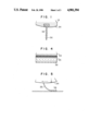
- FIG. 1 is a cross-sectional view illustrating an essential part of an agitator which is one embodiment of the invention
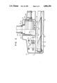
- FIG. 2 is a plan view illustrating a floor nozzle from which an upper body portion has been removed
- FIG. 3 is a cross-sectional view illustrating the floor nozzle shown in FIG. 2;
- FIG. 4 is a side elevation view illustrating the essential part of the agitator.
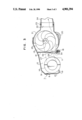
- FIG. 5 is a view illustrating operation of the agitator.
- FIGS. 1 to 4 there is shown a floor nozzle body 7 composed of upper and lower body members 9 and 10 which are coupled together through the intermediary of a bumper 8.
- a suction chamber 12 having a lower opening as a suction port 11 is formed in a front inner portion of the nozzle body 7, and a turbine chamber 13 is formed in a rear inner portion of the nozzle body 7.
- the turbine chamber 13 is separated from the suction chamber 12 by a partition wall 14. Also, its rear portion having an opening 15 is formed in an arcuate shape.
- An agitator 16 is arranged in parallel with the suction chamber 12 within the suction chamber 12.
- a pair of bearings 17 are provided for the agitator 16 on opposite side walls of the suction chamber 12.
- a stationary brush 18 is arranged in the rear of the suction port 11 in parallel therewith.
- Wheels 19 and 20 are provided to front and rear portions of the floor nozzle body 1, so as to obtain a predetermined space between the floor nozzle body 1 and the floor to be cleaned.
- a substantially semicylindrical suction joint 21 is slidably and rotatably arranged on the inner rear surface of the turbine chamber 13.
- a floor nozzle pipe 24 is rotatably fitted on a cylindrical connection port 22 projected from a part of the circumferential wall of the suction joint 21 through the intermedialy of a ring 23.
- an extension tube which is communicated to the suction side of the vacuum cleaner through a hose is detachably connected to the floor nozzle pipe 24.
- a turbine 25 is arranged in the turbine chamber 13 and partially surrounded by the suction joint 21 along the circumference of the turbine.
- a shaft 26 is integrally formed with the turbine 25 and passed through the suction joint 21 on one side.
- a power transmission belt 27 is used to transmit the rotation of the turbine 25 to the agitator 16 through a pulley 28.
- the turbine 25 is set aside to the belt 27 within the turbine chamber 13.
- Vent holes 29 and 30 are formed in the partition wall 14, one vent hole 29 being confronted by the lower half portion of the turbine 25 and the other vent hole 30 being not confronted by the turbine 25 but directly by the connection port 22 of the suction joint 21.
- a switching lever 31 has a shielding plate 32 extending from a part of the switching lever 31, and formed therein with an opening 33 adapted to be selectively communicated with one of the vent ports 29, 30.
- the agitator 16 is formed with spiral lips 35 along the longitudinal outer direction of the rotor 34.
- Each lip 35 is made of flexible material such as vulcanized urethane rubber and is provided with a number of projections 36 on at least one surface thereof (surface in the rotational direction).
- the lip 35 When the agitator 16 is rotated in the clockwise direction as shown in FIG. 5, the lip 35 is shifted in the opposite direction to the rotational direction at the position contact with the surface to be cleaned and is deformed in conformity with the surface to be cleaned. Thereafter, the lip 35 skips relative to the surface to be cleaned while rubbing the surface. At this time, the dust is rubbed by the projections 36 of the lip so as to be removed away from the surface to be cleaned.
- the free dust is effectively introduced into the floor nozzle body 7 by the suction force of the vacuum cleaner and the repulsive force effected when the lip 35 is restored in the radial direction (due to the flexibility and centrifugal force).
- the lip 35 is used to interrupt the flow of the air from the front side when it is brought into contact with the surface to be cleaned, whereby the suction force of the vacuum cleaner is concentrated on the surface to be cleaned and acts thereon with the assistance of the lip 35.
- the lip 35 is in the form of a band, it is possible to prevent strings or the like from being entangled around the lip.
- the lips 35 each mounted in the circumferential and longitudinal direction of the rotor 34 serve to remove dust away from the surface to be cleaned and to impart the repulsive action to the dust.
- These lips are the basic members for determining the dust collection performance.
- the agitator is rotated at a high speed of 3,000 to 4,000 rpm, is brought into press contact with the carpet surface and is reciprocatingly moved back and forth.
- the agitator must have a durability over five years under the above-mentioned use. It is also necessary to ensure the durable service life of the lips over 500 hours. In order to meet this requirement, the lips should have the following properties:
- the lips must fit the surface to be cleaned and their surfaces have the function to rub the carpet surface.
- the lips need the repulsive property and restoring property.
- the lips must have flexibility and high repulsive performance.
- vulcanized polyurethane rubber is used as the molding material in order to meet all the requirements. Since the vulcanized polyurethane rubber sufficiently meets the practical strength without using carbon black as the reinforcement, there is no fear that the floor surface would be contaminated by black color. However, since the lips needs melting resistance and friction resistance and must be used in a particularly severe condition, 30 to 60 parts of talc is added into 100 parts of vulcanized polyurethane rubber in order to reduce the friction coefficient and to enhance the reinforcement effect, thereby ensuring long service life of the floor nozzle over five years and the durability of the lips over 500 hours.
- the lips When the lips are brought into contact with the surface to be cleaned, the lips must fit the surface to free dust away from the surface and to introduce the freed dust into the floor nozzle body by the restoring force of the lips. Thus, the lips must have high elasticity, a high creep characteristic and high flexibility.
- the hardness thereof is preferably in a range of 50 to 70. This hardness is measured under Durometer hardness, shore A of ASTM D-2240.
- the physical property of the vulcanized polyurethane rubber used for the lips molded under the above-described condition is as follows (ASTM D-2240, Durometer Hardness, Shore A):
- the vulcanized polyurethane rubber is used as a molding material for the lips provided in the longitudinal direction of the rotor circumferential surface of the agitator, and 30 to 60 parts of talc is added to the polyurethane rubber (100 parts) as additives.
- the vulcanized polyurethane rubber satisfies the practical strength with no use of carbon black which is essential in natural rubber and chloroprene rubber.
- carbon black which is essential in natural rubber and chloroprene rubber.
- the lips requires high melting resistance and wear resistance and must endures under severe conditions in use. Therefore, although it is sufficient to have wear resistance alone for the vulcanized polyurethane rubber alone, the present invention proposes that talc is added to vulcanized polyurethane rubber thereby considerably reducing the friction coefficient and surely enhancing the service life.
- the hardness of the lips is set in the range of 50 to 70 (ASTM D-2240, Durometer Hardness, Shore A).
- the lips are inferior in resistance of weather discoloration such as yellow discoloration by ultraviolet rays, and it requires severe management in molding ability since the appearance defect rate is liable to be increased due to spotted burns or contamination during the molding process.
- a small amount of coloring agent such as carbon black is added by 0.1 to 0.5% to color the lips slightly. This does not cause the floor contamination and makes it possible to improve the above-mentioned disadvantages.
Abstract
Description
______________________________________
                      Blending amount
Blended Agents        (Parts)
______________________________________
polyether modified
urethane rubber
Takenate E-3000       100
talc, crown talc      30 to 60
titanium oxide        5 to 15
zinc stearin acid     0.1 to 1.0
coloring carbon FEF class
                      0.1 to 0.5
vulcanization accelerator M
                      0.5 to 2.5
vulcanization accelerator DM
                      0.5 to 2.5
vulcanization accelerator PZ
                      0.5 to 2.0
active trimethyrol propane,
trimethacrylate       0.5 to 2.0
sulfur 200 meshed powder
                      1.0 to 1.5
Vulcanization Condition
temperature: 110 to 150° C.
period: 8 to 30 minutes
pressure: 20 to 50 kg/cm.sup.2
______________________________________
Claims (4)
Applications Claiming Priority (2)
| Application Number | Priority Date | Filing Date | Title |
|---|---|---|---|
| JP63097100A JP2583958B2 (en) | 1988-04-20 | 1988-04-20 | Floor nozzle for vacuum cleaner |
| JP63-97100 | 1988-04-20 |
Publications (1)
| Publication Number | Publication Date |
|---|---|
| US4901394A true US4901394A (en) | 1990-02-20 |
Family
ID=14183199
Family Applications (1)
| Application Number | Title | Priority Date | Filing Date |
|---|---|---|---|
| US07/339,114 Expired - Lifetime US4901394A (en) | 1988-04-20 | 1989-04-17 | Floor nozzle for electric cleaner |
Country Status (5)
| Country | Link |
|---|---|
| US (1) | US4901394A (en) |
| EP (1) | EP0338780B1 (en) |
| JP (1) | JP2583958B2 (en) |
| DE (1) | DE68911572T2 (en) |
| ES (1) | ES2047671T3 (en) |
Cited By (37)
| Publication number | Priority date | Publication date | Assignee | Title |
|---|---|---|---|---|
| USD431698S (en) * | 1999-04-28 | 2000-10-03 | Matsushita Electric Industrial Co., Ltd. | Rotary brush for electric vacuum cleaner |
| US6532619B2 (en) | 2000-06-19 | 2003-03-18 | Bissell Homecare, Inc. | Extraction cleaner and agitator therefor |
| US20030163891A1 (en) * | 1998-07-28 | 2003-09-04 | Sharp Kabushiki Kaisha | Electric vacuum cleaner and nozzle unit therefor |
| US20040010878A1 (en) * | 2002-07-16 | 2004-01-22 | Levesque Gary H. | Vehicle cleaning element |
| US20040049877A1 (en) * | 2002-01-03 | 2004-03-18 | Jones Joseph L. | Autonomous floor-cleaning robot |
| US20040187249A1 (en) * | 2002-01-03 | 2004-09-30 | Jones Joseph L. | Autonomous floor-cleaning robot |
| US20050156562A1 (en) * | 2004-01-21 | 2005-07-21 | Irobot Corporation | Autonomous robot auto-docking and energy management systems and methods |
| US20050251292A1 (en) * | 2000-01-24 | 2005-11-10 | Irobot Corporation | Obstacle following sensor scheme for a mobile robot |
| US20050287038A1 (en) * | 2004-06-24 | 2005-12-29 | Zivthan Dubrovsky | Remote control scheduler and method for autonomous robotic device |
| US20060190146A1 (en) * | 2005-02-18 | 2006-08-24 | Irobot Corporation | Autonomous surface cleaning robot for dry cleaning |
| US20060190133A1 (en) * | 2005-02-18 | 2006-08-24 | Irobot Corporation | Autonomous surface cleaning robot for wet cleaning |
| US20060190134A1 (en) * | 2005-02-18 | 2006-08-24 | Irobot Corporation | Autonomous surface cleaning robot for wet and dry cleaning |
| US7155308B2 (en) | 2000-01-24 | 2006-12-26 | Irobot Corporation | Robot obstacle detection system |
| US20070016328A1 (en) * | 2005-02-18 | 2007-01-18 | Andrew Ziegler | Autonomous surface cleaning robot for wet and dry cleaning |
| US20070179670A1 (en) * | 2002-01-24 | 2007-08-02 | Irobot Corporation | Navigational control system for a robotic device |
| US20070244610A1 (en) * | 2005-12-02 | 2007-10-18 | Ozick Daniel N | Autonomous coverage robot navigation system |
| US20070250212A1 (en) * | 2005-12-02 | 2007-10-25 | Halloran Michael J | Robot system |
| US20080015738A1 (en) * | 2000-01-24 | 2008-01-17 | Irobot Corporation | Obstacle Following Sensor Scheme for a mobile robot |
| US20080047092A1 (en) * | 2006-05-19 | 2008-02-28 | Irobot Corporation | Coverage robots and associated cleaning bins |
| US20080065265A1 (en) * | 2006-05-31 | 2008-03-13 | Irobot Corporation | Detecting robot stasis |
| US20080084174A1 (en) * | 2001-01-24 | 2008-04-10 | Irobot Corporation | Robot Confinement |
| US20080091305A1 (en) * | 2005-12-02 | 2008-04-17 | Irobot Corporation | Coverage robot mobility |
| US7388343B2 (en) | 2001-06-12 | 2008-06-17 | Irobot Corporation | Method and system for multi-mode coverage for an autonomous robot |
| US20080150466A1 (en) * | 2004-01-28 | 2008-06-26 | Landry Gregg W | Debris Sensor for Cleaning Apparatus |
| US20080276408A1 (en) * | 2007-05-09 | 2008-11-13 | Irobot Corporation | Autonomous coverage robot |
| US7706917B1 (en) | 2004-07-07 | 2010-04-27 | Irobot Corporation | Celestial navigation system for an autonomous robot |
| US20100101044A1 (en) * | 2008-10-29 | 2010-04-29 | Craig John Salmond | Beater bar with air injector |
| US20110125323A1 (en) * | 2009-11-06 | 2011-05-26 | Evolution Robotics, Inc. | Localization by learning of wave-signal distributions |
| EP2554086A2 (en) * | 2010-03-29 | 2013-02-06 | Yujin Robot Co., Ltd. | Dust collection blade structure for cleaning robot and cleaning robot having same |
| US8386081B2 (en) | 2002-09-13 | 2013-02-26 | Irobot Corporation | Navigational control system for a robotic device |
| US8396592B2 (en) | 2001-06-12 | 2013-03-12 | Irobot Corporation | Method and system for multi-mode coverage for an autonomous robot |
| US8584305B2 (en) | 2005-12-02 | 2013-11-19 | Irobot Corporation | Modular robot |
| US8780342B2 (en) | 2004-03-29 | 2014-07-15 | Irobot Corporation | Methods and apparatus for position estimation using reflected light sources |
| US8800107B2 (en) | 2010-02-16 | 2014-08-12 | Irobot Corporation | Vacuum brush |
| US8972052B2 (en) | 2004-07-07 | 2015-03-03 | Irobot Corporation | Celestial navigation system for an autonomous vehicle |
| US9320398B2 (en) | 2005-12-02 | 2016-04-26 | Irobot Corporation | Autonomous coverage robots |
| US9949608B2 (en) | 2002-09-13 | 2018-04-24 | Irobot Corporation | Navigational control system for a robotic device |
Families Citing this family (12)
| Publication number | Priority date | Publication date | Assignee | Title |
|---|---|---|---|---|
| DE4105336C2 (en) * | 1991-02-21 | 1994-08-25 | Fedag Romanshorn Fa | Suction cleaning tool |
| DE4108900C2 (en) * | 1991-03-19 | 1998-06-10 | Fedag Romanshorn Fa | Suction cleaning tool with adjustable suction air flow |
| DE19602406C1 (en) * | 1996-01-24 | 1997-01-23 | Wessel Werk Gmbh | Domestic vacuum cleaner suction head |
| SE9800583D0 (en) * | 1998-02-26 | 1998-02-26 | Electrolux Ab | Nozzle |
| DE19826041C5 (en) * | 1998-06-12 | 2006-03-30 | Düpro AG | vacuum cleaning tool |
| EP1145677B1 (en) * | 2000-04-13 | 2001-11-14 | Wessel-Werk Gmbh | Suction nozzle for vacuum cleaner |
| CN1131011C (en) | 2000-11-24 | 2003-12-17 | 维斯尔-韦克有限公司 | Brush attachment for vacuum suction cleaner |
| DE10110312C1 (en) * | 2001-03-03 | 2002-10-02 | Duepro Ag Romanshorn | Suction cleaning tool with rotating brush roller |
| US8738787B2 (en) | 2005-04-20 | 2014-05-27 | Limelight Networks, Inc. | Ad server integration |
| US8402600B2 (en) | 2006-12-13 | 2013-03-26 | Ab Electrolux | Vacuum cleaner nozzle and roller |
| KR20110006236A (en) * | 2009-07-14 | 2011-01-20 | 삼성광주전자 주식회사 | Brush unit of vacuum cleaner and vacuum cleaner |
| US20210330161A1 (en) * | 2020-04-24 | 2021-10-28 | Techtronic Cordless Gp | Rotary working element |
Citations (7)
| Publication number | Priority date | Publication date | Assignee | Title |
|---|---|---|---|---|
| US862053A (en) * | 1905-10-28 | 1907-07-30 | American Carpet Beater Co | Carpet-beating machine. |
| US1740525A (en) * | 1927-08-04 | 1929-12-24 | Lawrence G Pritz | Vacuum cleaner |
| US1919067A (en) * | 1932-10-07 | 1933-07-18 | Electric Vacuum Cleaner Co | Beater for vacuum cleaners |
| US2537523A (en) * | 1948-04-09 | 1951-01-09 | Clements A Frost | Portable vacuum cleaner |
| US2578549A (en) * | 1948-07-26 | 1951-12-11 | Robert O Hooban | Power-driven clothes-cleaning brush |
| GB685208A (en) * | 1949-07-01 | 1952-12-31 | James Francis Armstrong Blue | Improvements in and relating to carpet sweepers, vacuum cleaners and textile finishing machines |
| US4445245A (en) * | 1982-08-23 | 1984-05-01 | Lu Ning K | Surface sweeper |
Family Cites Families (5)
| Publication number | Priority date | Publication date | Assignee | Title |
|---|---|---|---|---|
| US1267304A (en) * | 1917-11-27 | 1918-05-21 | James P N Adams | Carpet-sweeper brush. |
| NL289013A (en) * | 1963-02-14 | |||
| DE2253227A1 (en) * | 1972-10-30 | 1974-05-16 | Joh Jos Volberg Gmbh & Co Kg | Aerogel/talc filler for hard plastics - such as polyesters, cross-linked polyurethanes and ethoxylene resins, to increase hardness and tenacity |
| JPS6133634A (en) * | 1984-07-25 | 1986-02-17 | 株式会社ホ−キイ | Rotary cleaning body in cleaner |
| ES2040353T3 (en) * | 1987-10-23 | 1993-10-16 | Matsushita Electric Industrial Co., Ltd. | FLOOR SUCTION CUP FOR USE WITH A VACUUM CLEANER. |
-
1988
- 1988-04-20 JP JP63097100A patent/JP2583958B2/en not_active Expired - Fee Related
-
1989
- 1989-04-17 US US07/339,114 patent/US4901394A/en not_active Expired - Lifetime
- 1989-04-18 DE DE68911572T patent/DE68911572T2/en not_active Expired - Fee Related
- 1989-04-18 EP EP89303836A patent/EP0338780B1/en not_active Expired - Lifetime
- 1989-04-18 ES ES89303836T patent/ES2047671T3/en not_active Expired - Lifetime
Patent Citations (7)
| Publication number | Priority date | Publication date | Assignee | Title |
|---|---|---|---|---|
| US862053A (en) * | 1905-10-28 | 1907-07-30 | American Carpet Beater Co | Carpet-beating machine. |
| US1740525A (en) * | 1927-08-04 | 1929-12-24 | Lawrence G Pritz | Vacuum cleaner |
| US1919067A (en) * | 1932-10-07 | 1933-07-18 | Electric Vacuum Cleaner Co | Beater for vacuum cleaners |
| US2537523A (en) * | 1948-04-09 | 1951-01-09 | Clements A Frost | Portable vacuum cleaner |
| US2578549A (en) * | 1948-07-26 | 1951-12-11 | Robert O Hooban | Power-driven clothes-cleaning brush |
| GB685208A (en) * | 1949-07-01 | 1952-12-31 | James Francis Armstrong Blue | Improvements in and relating to carpet sweepers, vacuum cleaners and textile finishing machines |
| US4445245A (en) * | 1982-08-23 | 1984-05-01 | Lu Ning K | Surface sweeper |
Cited By (168)
| Publication number | Priority date | Publication date | Assignee | Title |
|---|---|---|---|---|
| US6742220B2 (en) * | 1998-07-28 | 2004-06-01 | Sharp Kabushiki Kaisha | Nozzle unit for vacuum cleaner |
| US20030163891A1 (en) * | 1998-07-28 | 2003-09-04 | Sharp Kabushiki Kaisha | Electric vacuum cleaner and nozzle unit therefor |
| USD431698S (en) * | 1999-04-28 | 2000-10-03 | Matsushita Electric Industrial Co., Ltd. | Rotary brush for electric vacuum cleaner |
| US8412377B2 (en) | 2000-01-24 | 2013-04-02 | Irobot Corporation | Obstacle following sensor scheme for a mobile robot |
| US8565920B2 (en) | 2000-01-24 | 2013-10-22 | Irobot Corporation | Obstacle following sensor scheme for a mobile robot |
| US20080015738A1 (en) * | 2000-01-24 | 2008-01-17 | Irobot Corporation | Obstacle Following Sensor Scheme for a mobile robot |
| US9446521B2 (en) | 2000-01-24 | 2016-09-20 | Irobot Corporation | Obstacle following sensor scheme for a mobile robot |
| US20090055022A1 (en) * | 2000-01-24 | 2009-02-26 | Irobot Corporation | Obstacle following sensor scheme for a mobile robot |
| US20050251292A1 (en) * | 2000-01-24 | 2005-11-10 | Irobot Corporation | Obstacle following sensor scheme for a mobile robot |
| US7430455B2 (en) | 2000-01-24 | 2008-09-30 | Irobot Corporation | Obstacle following sensor scheme for a mobile robot |
| US8478442B2 (en) | 2000-01-24 | 2013-07-02 | Irobot Corporation | Obstacle following sensor scheme for a mobile robot |
| US20090045766A1 (en) * | 2000-01-24 | 2009-02-19 | Irobot Corporation | Obstacle following sensor scheme for a mobile robot |
| US8788092B2 (en) | 2000-01-24 | 2014-07-22 | Irobot Corporation | Obstacle following sensor scheme for a mobile robot |
| US8761935B2 (en) | 2000-01-24 | 2014-06-24 | Irobot Corporation | Obstacle following sensor scheme for a mobile robot |
| US7155308B2 (en) | 2000-01-24 | 2006-12-26 | Irobot Corporation | Robot obstacle detection system |
| US9144361B2 (en) | 2000-04-04 | 2015-09-29 | Irobot Corporation | Debris sensor for cleaning apparatus |
| US6532619B2 (en) | 2000-06-19 | 2003-03-18 | Bissell Homecare, Inc. | Extraction cleaner and agitator therefor |
| US20080000042A1 (en) * | 2001-01-24 | 2008-01-03 | Irobot Corporation | Autonomous Floor Cleaning Robot |
| US8659256B2 (en) | 2001-01-24 | 2014-02-25 | Irobot Corporation | Robot confinement |
| US9038233B2 (en) | 2001-01-24 | 2015-05-26 | Irobot Corporation | Autonomous floor-cleaning robot |
| US9582005B2 (en) | 2001-01-24 | 2017-02-28 | Irobot Corporation | Robot confinement |
| US20090319083A1 (en) * | 2001-01-24 | 2009-12-24 | Irobot Corporation | Robot Confinement |
| US9167946B2 (en) | 2001-01-24 | 2015-10-27 | Irobot Corporation | Autonomous floor cleaning robot |
| US8659255B2 (en) | 2001-01-24 | 2014-02-25 | Irobot Corporation | Robot confinement |
| US8368339B2 (en) | 2001-01-24 | 2013-02-05 | Irobot Corporation | Robot confinement |
| US7567052B2 (en) | 2001-01-24 | 2009-07-28 | Irobot Corporation | Robot navigation |
| US9622635B2 (en) | 2001-01-24 | 2017-04-18 | Irobot Corporation | Autonomous floor-cleaning robot |
| US20100312429A1 (en) * | 2001-01-24 | 2010-12-09 | Irobot Corporation | Robot confinement |
| US20100268384A1 (en) * | 2001-01-24 | 2010-10-21 | Irobot Corporation | Robot confinement |
| US7579803B2 (en) | 2001-01-24 | 2009-08-25 | Irobot Corporation | Robot confinement |
| US20080084174A1 (en) * | 2001-01-24 | 2008-04-10 | Irobot Corporation | Robot Confinement |
| US8463438B2 (en) | 2001-06-12 | 2013-06-11 | Irobot Corporation | Method and system for multi-mode coverage for an autonomous robot |
| US7663333B2 (en) | 2001-06-12 | 2010-02-16 | Irobot Corporation | Method and system for multi-mode coverage for an autonomous robot |
| US20100049365A1 (en) * | 2001-06-12 | 2010-02-25 | Irobot Corporation | Method and System for Multi-Mode Coverage For An Autonomous Robot |
| US20100263142A1 (en) * | 2001-06-12 | 2010-10-21 | Irobot Corporation | Method and system for multi-mode coverage for an autonomous robot |
| US8396592B2 (en) | 2001-06-12 | 2013-03-12 | Irobot Corporation | Method and system for multi-mode coverage for an autonomous robot |
| US7388343B2 (en) | 2001-06-12 | 2008-06-17 | Irobot Corporation | Method and system for multi-mode coverage for an autonomous robot |
| US8838274B2 (en) | 2001-06-12 | 2014-09-16 | Irobot Corporation | Method and system for multi-mode coverage for an autonomous robot |
| US9104204B2 (en) | 2001-06-12 | 2015-08-11 | Irobot Corporation | Method and system for multi-mode coverage for an autonomous robot |
| US7429843B2 (en) | 2001-06-12 | 2008-09-30 | Irobot Corporation | Method and system for multi-mode coverage for an autonomous robot |
| US7448113B2 (en) | 2002-01-03 | 2008-11-11 | Irobert | Autonomous floor cleaning robot |
| US6883201B2 (en) | 2002-01-03 | 2005-04-26 | Irobot Corporation | Autonomous floor-cleaning robot |
| US20100257691A1 (en) * | 2002-01-03 | 2010-10-14 | Irobot Corporation | Autonomous floor-cleaning robot |
| US20070266508A1 (en) * | 2002-01-03 | 2007-11-22 | Irobot Corporation | Autonomous Floor Cleaning Robot |
| US20100257690A1 (en) * | 2002-01-03 | 2010-10-14 | Irobot Corporation | Autonomous floor-cleaning robot |
| US20040049877A1 (en) * | 2002-01-03 | 2004-03-18 | Jones Joseph L. | Autonomous floor-cleaning robot |
| US8474090B2 (en) | 2002-01-03 | 2013-07-02 | Irobot Corporation | Autonomous floor-cleaning robot |
| US20080307590A1 (en) * | 2002-01-03 | 2008-12-18 | Irobot Corporation | Autonomous Floor-Cleaning Robot |
| US8763199B2 (en) | 2002-01-03 | 2014-07-01 | Irobot Corporation | Autonomous floor-cleaning robot |
| US20040187249A1 (en) * | 2002-01-03 | 2004-09-30 | Jones Joseph L. | Autonomous floor-cleaning robot |
| US8671507B2 (en) | 2002-01-03 | 2014-03-18 | Irobot Corporation | Autonomous floor-cleaning robot |
| US8516651B2 (en) | 2002-01-03 | 2013-08-27 | Irobot Corporation | Autonomous floor-cleaning robot |
| US7571511B2 (en) | 2002-01-03 | 2009-08-11 | Irobot Corporation | Autonomous floor-cleaning robot |
| US20100263158A1 (en) * | 2002-01-03 | 2010-10-21 | Irobot Corporation | Autonomous floor-cleaning robot |
| US8656550B2 (en) | 2002-01-03 | 2014-02-25 | Irobot Corporation | Autonomous floor-cleaning robot |
| US20080000041A1 (en) * | 2002-01-03 | 2008-01-03 | Irobot Corporation | Autonomous Floor Cleaning Robot |
| US7636982B2 (en) | 2002-01-03 | 2009-12-29 | Irobot Corporation | Autonomous floor cleaning robot |
| US9128486B2 (en) | 2002-01-24 | 2015-09-08 | Irobot Corporation | Navigational control system for a robotic device |
| US20070179670A1 (en) * | 2002-01-24 | 2007-08-02 | Irobot Corporation | Navigational control system for a robotic device |
| US7051396B2 (en) * | 2002-07-16 | 2006-05-30 | Levesque Gary H | Vehicle cleaning element |
| US20040010878A1 (en) * | 2002-07-16 | 2004-01-22 | Levesque Gary H. | Vehicle cleaning element |
| US8793020B2 (en) | 2002-09-13 | 2014-07-29 | Irobot Corporation | Navigational control system for a robotic device |
| US8515578B2 (en) | 2002-09-13 | 2013-08-20 | Irobot Corporation | Navigational control system for a robotic device |
| US8386081B2 (en) | 2002-09-13 | 2013-02-26 | Irobot Corporation | Navigational control system for a robotic device |
| US9949608B2 (en) | 2002-09-13 | 2018-04-24 | Irobot Corporation | Navigational control system for a robotic device |
| US9215957B2 (en) | 2004-01-21 | 2015-12-22 | Irobot Corporation | Autonomous robot auto-docking and energy management systems and methods |
| US20050156562A1 (en) * | 2004-01-21 | 2005-07-21 | Irobot Corporation | Autonomous robot auto-docking and energy management systems and methods |
| US7332890B2 (en) | 2004-01-21 | 2008-02-19 | Irobot Corporation | Autonomous robot auto-docking and energy management systems and methods |
| US20080007203A1 (en) * | 2004-01-21 | 2008-01-10 | Irobot Corporation | Autonomous robot auto-docking and energy management systems and methods |
| US8390251B2 (en) | 2004-01-21 | 2013-03-05 | Irobot Corporation | Autonomous robot auto-docking and energy management systems and methods |
| US20070114975A1 (en) * | 2004-01-21 | 2007-05-24 | Irobot Corporation | Autonomous robot auto-docking and energy management systems and methods |
| US8461803B2 (en) | 2004-01-21 | 2013-06-11 | Irobot Corporation | Autonomous robot auto-docking and energy management systems and methods |
| US20070267998A1 (en) * | 2004-01-21 | 2007-11-22 | Irobot Corporation | Autonomous Robot Auto-Docking and Energy Management Systems and Methods |
| US8854001B2 (en) | 2004-01-21 | 2014-10-07 | Irobot Corporation | Autonomous robot auto-docking and energy management systems and methods |
| US8749196B2 (en) | 2004-01-21 | 2014-06-10 | Irobot Corporation | Autonomous robot auto-docking and energy management systems and methods |
| US8253368B2 (en) | 2004-01-28 | 2012-08-28 | Irobot Corporation | Debris sensor for cleaning apparatus |
| US8378613B2 (en) | 2004-01-28 | 2013-02-19 | Irobot Corporation | Debris sensor for cleaning apparatus |
| US20090038089A1 (en) * | 2004-01-28 | 2009-02-12 | Irobot Corporation | Debris Sensor for Cleaning Apparatus |
| US7459871B2 (en) | 2004-01-28 | 2008-12-02 | Irobot Corporation | Debris sensor for cleaning apparatus |
| US20100115716A1 (en) * | 2004-01-28 | 2010-05-13 | Irobot Corporation | Debris Sensor for Cleaning Apparatus |
| US8456125B2 (en) | 2004-01-28 | 2013-06-04 | Irobot Corporation | Debris sensor for cleaning apparatus |
| US20080150466A1 (en) * | 2004-01-28 | 2008-06-26 | Landry Gregg W | Debris Sensor for Cleaning Apparatus |
| US9360300B2 (en) | 2004-03-29 | 2016-06-07 | Irobot Corporation | Methods and apparatus for position estimation using reflected light sources |
| US8780342B2 (en) | 2004-03-29 | 2014-07-15 | Irobot Corporation | Methods and apparatus for position estimation using reflected light sources |
| US9008835B2 (en) | 2004-06-24 | 2015-04-14 | Irobot Corporation | Remote control scheduler and method for autonomous robotic device |
| US9486924B2 (en) | 2004-06-24 | 2016-11-08 | Irobot Corporation | Remote control scheduler and method for autonomous robotic device |
| US20050287038A1 (en) * | 2004-06-24 | 2005-12-29 | Zivthan Dubrovsky | Remote control scheduler and method for autonomous robotic device |
| US9229454B1 (en) | 2004-07-07 | 2016-01-05 | Irobot Corporation | Autonomous mobile robot system |
| US7706917B1 (en) | 2004-07-07 | 2010-04-27 | Irobot Corporation | Celestial navigation system for an autonomous robot |
| US8874264B1 (en) | 2004-07-07 | 2014-10-28 | Irobot Corporation | Celestial navigation system for an autonomous robot |
| US8634956B1 (en) | 2004-07-07 | 2014-01-21 | Irobot Corporation | Celestial navigation system for an autonomous robot |
| US8972052B2 (en) | 2004-07-07 | 2015-03-03 | Irobot Corporation | Celestial navigation system for an autonomous vehicle |
| US8594840B1 (en) | 2004-07-07 | 2013-11-26 | Irobot Corporation | Celestial navigation system for an autonomous robot |
| US9223749B2 (en) | 2004-07-07 | 2015-12-29 | Irobot Corporation | Celestial navigation system for an autonomous vehicle |
| US8985127B2 (en) | 2005-02-18 | 2015-03-24 | Irobot Corporation | Autonomous surface cleaning robot for wet cleaning |
| US8855813B2 (en) | 2005-02-18 | 2014-10-07 | Irobot Corporation | Autonomous surface cleaning robot for wet and dry cleaning |
| US7620476B2 (en) | 2005-02-18 | 2009-11-17 | Irobot Corporation | Autonomous surface cleaning robot for dry cleaning |
| US8382906B2 (en) | 2005-02-18 | 2013-02-26 | Irobot Corporation | Autonomous surface cleaning robot for wet cleaning |
| US20080155768A1 (en) * | 2005-02-18 | 2008-07-03 | Irobot Corporation | Autonomous surface cleaning robot for wet and dry cleaning |
| US7761954B2 (en) | 2005-02-18 | 2010-07-27 | Irobot Corporation | Autonomous surface cleaning robot for wet and dry cleaning |
| US9445702B2 (en) | 2005-02-18 | 2016-09-20 | Irobot Corporation | Autonomous surface cleaning robot for wet and dry cleaning |
| US8966707B2 (en) | 2005-02-18 | 2015-03-03 | Irobot Corporation | Autonomous surface cleaning robot for dry cleaning |
| US8387193B2 (en) | 2005-02-18 | 2013-03-05 | Irobot Corporation | Autonomous surface cleaning robot for wet and dry cleaning |
| US7389156B2 (en) | 2005-02-18 | 2008-06-17 | Irobot Corporation | Autonomous surface cleaning robot for wet and dry cleaning |
| US8392021B2 (en) | 2005-02-18 | 2013-03-05 | Irobot Corporation | Autonomous surface cleaning robot for wet cleaning |
| US20080127446A1 (en) * | 2005-02-18 | 2008-06-05 | Irobot Corporation | Autonomous surface cleaning robot for wet and dry cleaning |
| US20070016328A1 (en) * | 2005-02-18 | 2007-01-18 | Andrew Ziegler | Autonomous surface cleaning robot for wet and dry cleaning |
| US20060190146A1 (en) * | 2005-02-18 | 2006-08-24 | Irobot Corporation | Autonomous surface cleaning robot for dry cleaning |
| US8670866B2 (en) | 2005-02-18 | 2014-03-11 | Irobot Corporation | Autonomous surface cleaning robot for wet and dry cleaning |
| US10470629B2 (en) | 2005-02-18 | 2019-11-12 | Irobot Corporation | Autonomous surface cleaning robot for dry cleaning |
| US20060190133A1 (en) * | 2005-02-18 | 2006-08-24 | Irobot Corporation | Autonomous surface cleaning robot for wet cleaning |
| US8739355B2 (en) | 2005-02-18 | 2014-06-03 | Irobot Corporation | Autonomous surface cleaning robot for dry cleaning |
| US8782848B2 (en) | 2005-02-18 | 2014-07-22 | Irobot Corporation | Autonomous surface cleaning robot for dry cleaning |
| US8774966B2 (en) | 2005-02-18 | 2014-07-08 | Irobot Corporation | Autonomous surface cleaning robot for wet and dry cleaning |
| US20060190134A1 (en) * | 2005-02-18 | 2006-08-24 | Irobot Corporation | Autonomous surface cleaning robot for wet and dry cleaning |
| US9320398B2 (en) | 2005-12-02 | 2016-04-26 | Irobot Corporation | Autonomous coverage robots |
| US20080091304A1 (en) * | 2005-12-02 | 2008-04-17 | Irobot Corporation | Navigating autonomous coverage robots |
| US10524629B2 (en) | 2005-12-02 | 2020-01-07 | Irobot Corporation | Modular Robot |
| US7441298B2 (en) | 2005-12-02 | 2008-10-28 | Irobot Corporation | Coverage robot mobility |
| US9599990B2 (en) | 2005-12-02 | 2017-03-21 | Irobot Corporation | Robot system |
| US20070250212A1 (en) * | 2005-12-02 | 2007-10-25 | Halloran Michael J | Robot system |
| US20070244610A1 (en) * | 2005-12-02 | 2007-10-18 | Ozick Daniel N | Autonomous coverage robot navigation system |
| US8661605B2 (en) | 2005-12-02 | 2014-03-04 | Irobot Corporation | Coverage robot mobility |
| US9392920B2 (en) | 2005-12-02 | 2016-07-19 | Irobot Corporation | Robot system |
| US8380350B2 (en) | 2005-12-02 | 2013-02-19 | Irobot Corporation | Autonomous coverage robot navigation system |
| US20080058987A1 (en) * | 2005-12-02 | 2008-03-06 | Irobot Corporation | Navigating autonomous coverage robots |
| US8374721B2 (en) | 2005-12-02 | 2013-02-12 | Irobot Corporation | Robot system |
| US8761931B2 (en) | 2005-12-02 | 2014-06-24 | Irobot Corporation | Robot system |
| US8954192B2 (en) | 2005-12-02 | 2015-02-10 | Irobot Corporation | Navigating autonomous coverage robots |
| US8950038B2 (en) | 2005-12-02 | 2015-02-10 | Irobot Corporation | Modular robot |
| US8606401B2 (en) | 2005-12-02 | 2013-12-10 | Irobot Corporation | Autonomous coverage robot navigation system |
| US8600553B2 (en) | 2005-12-02 | 2013-12-03 | Irobot Corporation | Coverage robot mobility |
| US8978196B2 (en) | 2005-12-02 | 2015-03-17 | Irobot Corporation | Coverage robot mobility |
| US8584305B2 (en) | 2005-12-02 | 2013-11-19 | Irobot Corporation | Modular robot |
| US20080091305A1 (en) * | 2005-12-02 | 2008-04-17 | Irobot Corporation | Coverage robot mobility |
| US9149170B2 (en) | 2005-12-02 | 2015-10-06 | Irobot Corporation | Navigating autonomous coverage robots |
| US9144360B2 (en) | 2005-12-02 | 2015-09-29 | Irobot Corporation | Autonomous coverage robot navigation system |
| US9492048B2 (en) | 2006-05-19 | 2016-11-15 | Irobot Corporation | Removing debris from cleaning robots |
| US8418303B2 (en) | 2006-05-19 | 2013-04-16 | Irobot Corporation | Cleaning robot roller processing |
| US10244915B2 (en) | 2006-05-19 | 2019-04-02 | Irobot Corporation | Coverage robots and associated cleaning bins |
| US20080052846A1 (en) * | 2006-05-19 | 2008-03-06 | Irobot Corporation | Cleaning robot roller processing |
| US8572799B2 (en) | 2006-05-19 | 2013-11-05 | Irobot Corporation | Removing debris from cleaning robots |
| US9955841B2 (en) | 2006-05-19 | 2018-05-01 | Irobot Corporation | Removing debris from cleaning robots |
| US8528157B2 (en) | 2006-05-19 | 2013-09-10 | Irobot Corporation | Coverage robots and associated cleaning bins |
| US8087117B2 (en) | 2006-05-19 | 2012-01-03 | Irobot Corporation | Cleaning robot roller processing |
| US20080047092A1 (en) * | 2006-05-19 | 2008-02-28 | Irobot Corporation | Coverage robots and associated cleaning bins |
| US20080065265A1 (en) * | 2006-05-31 | 2008-03-13 | Irobot Corporation | Detecting robot stasis |
| US9317038B2 (en) | 2006-05-31 | 2016-04-19 | Irobot Corporation | Detecting robot stasis |
| US8417383B2 (en) | 2006-05-31 | 2013-04-09 | Irobot Corporation | Detecting robot stasis |
| US8239992B2 (en) | 2007-05-09 | 2012-08-14 | Irobot Corporation | Compact autonomous coverage robot |
| US10299652B2 (en) | 2007-05-09 | 2019-05-28 | Irobot Corporation | Autonomous coverage robot |
| US9480381B2 (en) | 2007-05-09 | 2016-11-01 | Irobot Corporation | Compact autonomous coverage robot |
| US8438695B2 (en) | 2007-05-09 | 2013-05-14 | Irobot Corporation | Autonomous coverage robot sensing |
| US11498438B2 (en) | 2007-05-09 | 2022-11-15 | Irobot Corporation | Autonomous coverage robot |
| US20080281470A1 (en) * | 2007-05-09 | 2008-11-13 | Irobot Corporation | Autonomous coverage robot sensing |
| US8726454B2 (en) | 2007-05-09 | 2014-05-20 | Irobot Corporation | Autonomous coverage robot |
| US20080276408A1 (en) * | 2007-05-09 | 2008-11-13 | Irobot Corporation | Autonomous coverage robot |
| US8839477B2 (en) | 2007-05-09 | 2014-09-23 | Irobot Corporation | Compact autonomous coverage robot |
| US11072250B2 (en) | 2007-05-09 | 2021-07-27 | Irobot Corporation | Autonomous coverage robot sensing |
| US10070764B2 (en) | 2007-05-09 | 2018-09-11 | Irobot Corporation | Compact autonomous coverage robot |
| US20100101044A1 (en) * | 2008-10-29 | 2010-04-29 | Craig John Salmond | Beater bar with air injector |
| US8930023B2 (en) | 2009-11-06 | 2015-01-06 | Irobot Corporation | Localization by learning of wave-signal distributions |
| US20110125323A1 (en) * | 2009-11-06 | 2011-05-26 | Evolution Robotics, Inc. | Localization by learning of wave-signal distributions |
| US10314449B2 (en) | 2010-02-16 | 2019-06-11 | Irobot Corporation | Vacuum brush |
| US11058271B2 (en) | 2010-02-16 | 2021-07-13 | Irobot Corporation | Vacuum brush |
| US8800107B2 (en) | 2010-02-16 | 2014-08-12 | Irobot Corporation | Vacuum brush |
| EP2554086A4 (en) * | 2010-03-29 | 2013-10-16 | Yujin Robot Co Ltd | Dust collection blade structure for cleaning robot and cleaning robot having same |
| EP2554086A2 (en) * | 2010-03-29 | 2013-02-06 | Yujin Robot Co., Ltd. | Dust collection blade structure for cleaning robot and cleaning robot having same |
Also Published As
| Publication number | Publication date |
|---|---|
| EP0338780A2 (en) | 1989-10-25 |
| ES2047671T3 (en) | 1994-03-01 |
| EP0338780B1 (en) | 1993-12-22 |
| JPH01268528A (en) | 1989-10-26 |
| DE68911572T2 (en) | 1994-06-09 |
| EP0338780A3 (en) | 1990-07-04 |
| DE68911572D1 (en) | 1994-02-03 |
| JP2583958B2 (en) | 1997-02-19 |
Similar Documents
| Publication | Publication Date | Title |
|---|---|---|
| US4901394A (en) | Floor nozzle for electric cleaner | |
| KR910009949B1 (en) | Floor nozzle for vacuum cleaner | |
| JP3192082B2 (en) | Resin pulley | |
| JP4256072B2 (en) | Vacuum cleaner head assembly used in vacuum cleaner | |
| US7849558B2 (en) | Head for a suction cleaner | |
| JPH02104321A (en) | Rotary brush | |
| JPS62120248A (en) | Wiper blade rubber | |
| CN101438945B (en) | Support assembly | |
| JP3551011B2 (en) | Vacuum cleaner mouthpiece | |
| JP4668677B2 (en) | Transmission belt | |
| US7096902B2 (en) | Vacuum cleaner | |
| CN104975733B (en) | Cleaning device | |
| CN1576305B (en) | Polyvinyl chloride-based elements for floor cleaning units | |
| JPH078420A (en) | Floor nozzle for electric vacuum cleaner | |
| JPH06249292A (en) | Toothed belt | |
| JP3061932B2 (en) | Floor nozzle for vacuum cleaner | |
| JP3626093B2 (en) | Resin pulley | |
| US2064852A (en) | Vacuum cleaner | |
| JP2627245B2 (en) | Anti-slip soles | |
| JPH04314411A (en) | Inlet port of vacuum cleaner | |
| US2627185A (en) | Transmission belt | |
| JPH04152923A (en) | Floor nozzle of vacuum cleaner | |
| CN116221129B (en) | High-strength sealed hot oil pump | |
| JP3890466B2 (en) | Manufacturing method of resin boot for constant velocity joint | |
| JP2008254300A (en) | Power transmission belt |
Legal Events
| Date | Code | Title | Description |
|---|---|---|---|
| AS | Assignment |
Owner name: MATSUSHITA ELECTRIC INDUSTRIAL CO., LTD., JAPAN, A Free format text: ASSIGNMENT OF ASSIGNORS INTEREST.;ASSIGNORS:NAKAMURA, KAZUO;MURATA, YOSHITAKA;KAWAKAMI, HIROSHI;AND OTHERS;REEL/FRAME:005064/0831 Effective date: 19890410 Owner name: NATIONAL TIRE COMPANY, LTD., A CORP. OF JAPAN, JAP Free format text: ASSIGNMENT OF ASSIGNORS INTEREST.;ASSIGNORS:NAKAMURA, KAZUO;MURATA, YOSHITAKA;KAWAKAMI, HIROSHI;AND OTHERS;REEL/FRAME:005064/0831 Effective date: 19890410 |
|
| STCF | Information on status: patent grant |
Free format text: PATENTED CASE |
|
| CC | Certificate of correction | ||
| FPAY | Fee payment |
Year of fee payment: 4 |
|
| FEPP | Fee payment procedure |
Free format text: PAYOR NUMBER ASSIGNED (ORIGINAL EVENT CODE: ASPN); ENTITY STATUS OF PATENT OWNER: LARGE ENTITY |
|
| FPAY | Fee payment |
Year of fee payment: 8 |
|
| FPAY | Fee payment |
Year of fee payment: 12 |