US4850686A - Apparatus for adjusting light beam direction - Google Patents
Apparatus for adjusting light beam direction Download PDFInfo
- Publication number
- US4850686A US4850686A US07/152,027 US15202788A US4850686A US 4850686 A US4850686 A US 4850686A US 15202788 A US15202788 A US 15202788A US 4850686 A US4850686 A US 4850686A
- Authority
- US
- United States
- Prior art keywords
- prism
- incident
- face
- light beam
- parallel
- Prior art date
- Legal status (The legal status is an assumption and is not a legal conclusion. Google has not performed a legal analysis and makes no representation as to the accuracy of the status listed.)
- Expired - Lifetime
Links
Images


Classifications
-
- G—PHYSICS
- G02—OPTICS
- G02B—OPTICAL ELEMENTS, SYSTEMS OR APPARATUS
- G02B26/00—Optical devices or arrangements for the control of light using movable or deformable optical elements
- G02B26/08—Optical devices or arrangements for the control of light using movable or deformable optical elements for controlling the direction of light
- G02B26/10—Scanning systems
-
- G—PHYSICS
- G02—OPTICS
- G02B—OPTICAL ELEMENTS, SYSTEMS OR APPARATUS
- G02B26/00—Optical devices or arrangements for the control of light using movable or deformable optical elements
- G02B26/08—Optical devices or arrangements for the control of light using movable or deformable optical elements for controlling the direction of light
- G02B26/0875—Optical devices or arrangements for the control of light using movable or deformable optical elements for controlling the direction of light by means of one or more refracting elements
- G02B26/0883—Optical devices or arrangements for the control of light using movable or deformable optical elements for controlling the direction of light by means of one or more refracting elements the refracting element being a prism
- G02B26/0891—Optical devices or arrangements for the control of light using movable or deformable optical elements for controlling the direction of light by means of one or more refracting elements the refracting element being a prism forming an optical wedge
Definitions
- the present invention relates to an apparatus for adjusting light beam direction of progress by making use of the relation between the incident angle and the deviation angle of a prism.
- the angle between the incident ray and the outgoing ray observed when monochromatic ray of light pass through a prism is regarded as deviation angle.
- the deviation angle becomes minimum when the incident angle is equal to the outgoing angle and, in an area around the minimum value, the rate of change in the deviation angle with respect to the variation of incident angle is low.
- the angle of the outgoing rays can be changed in a minute level while adjusting the incident angle of rays of light with respect to the prism in relatively large level.
- the incident faces and the outgoing faces of prisms 1 and 2 constituting the apparatus are parallel with an axis which is perpendicular to the incident direction of light beam.
- the direction of outgoing light beam is changed by rotating the prism 1 around a rotational axis L 1 parallel to the axis, in accordance with the aforementioned relation between the incident angle and the deviation angle.
- this state is defined as "zero-adjusting state”
- the alternation of the cross-sectional shape and the chromatic aberration can be eliminated.
- the incident light beam and the outgoing light beam cause a shift therebetween even if the incident and outgoing light beam are parallel to each other, it is quite difficult to properly arrange optical systems at the incident side and the outgoing side of the prisms.
- FIGS. 16-18 One example of an apparatus for 2-dimensionally adjusting light beam direction utilizing two prisms is shown in FIGS. 16-18.
- FIGS. 17 and 18 are diagrams illustrating how the prisms shown in FIG. 16 refract rays of light.
- FIG. 17 is a sectional view taken along a plane passing through the center of the prisms and parallel to x-y plane and
- FIG. 18 is a sectional view taken along a plane passing through the center of the prisms and parallel to x-z plane.
- two prisms are used. These prisms are arranged, in order, along the direction of progress of the incident light beam.
- the incident face of one prism is parallel to a plane which is assumed by rotating the vertical plane around a rotational axis parallel to the vertical plane by first acute angle
- the outgoing face thereof is parallel to a plane which is assumed by rotating the vertical plane in the same direction as the first acute angle around the rotational axis by second acute angle which is larger than the first one.
- the incident face of the other prism is parallel to the outgoing face of the first prism and the outgoing face thereof is parallel to the incident face of the first prism.
- At least one of these two prisms is designed so as to be able to adjustably rotate around a rotational axis parallel to the foregoing axis.
- the first such apparatus comprises a first group of prisms consisting of two prisms arranged in the same manner as in the aforementioned apparatus for one dimensionally adjusting light beam direction and a second group of prisms consisting of two other prisms arranged in the same manner as the first prisms. These two groups of prisms are arranged so that the rotational axes thereof are perpendicular to one another.
- the second such apparatus comprises two prisms having shapes different from those mentioned above.
- the first prism is designed to be able to rotate around a first rotational axis perpendicular to the incident direction of light beam, while the second prism is designed to be able to rotate around the second rotational axis perpendicular to both the incident direction and the first rotational axis.
- these two prisms are disposed so that the incident face of one prism is parallel to the outgoing face of the other prism and that two virtual intersectional lines formed when the incident face and the outgoing face of each prism are extended are non-parallel with respect to both the first and the second rotational axes.
- FIG. 1 is a diagram illustrating the arrangement and the construction of prisms in the first embodiment of the apparatus for adjusting light beam direction according to the present invention
- FIG. 2 is a diagram showing light path which is refracted by the apparatus for adjusting light beam direction shown in FIG. 1,
- FIG. 3 and 4 are diagrams showing light path refracted by variations of prism-arrangement, similar to that shown in FIG. 2;
- FIG. 5 is a diagram illustrating the arrangement and the construction of prisms in the second embodiment of the apparatus for adjusting light beam direction according to the present invention
- FIGS. 6 (a) and 6 (b) are diagrams illustrating light path which is refracted by the prisms shown in FIG. 5;
- FIGS. 7 (a) and 7 (b) are diagrams similar to FIG. 6 and illustrating light path refracted by variations of prism-arrangement
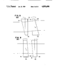
- FIG. 8 is a diagram showing the arrangement and the construction of prisms in the third embodiment of the apparatus for adjusting light beam direction according to the present invention.
- FIGS. 9 (a) and 9 (b) are diagrams showing light path refracted by the apparatus for adjusting light beam direction shown in FIG. 8;
- FIG. 10 is a decomposed perspective view illustrating an example of method for manufacturing the prism shown in FIG. 8;
- FIG. 11 is a diagram for illustrating a scanning optical apparatus in which the apparatus for adjusting light beam direction of the present invention is incorporated therein;
- FIG. 12 is a perspective view showing an example of an adjusting mechanism for prisms
- FIG. 13 is a diagram of light path for illustrating the relation between the incident angle and the deviation angle of a prism
- FIG. 14 is a graph showing the relation between the incident angle and the deviation angle of a prism
- FIG. 15 is a diagram of light path which is refracted by a conventional apparatus for one dimensionally effecting adjustment of light beam direction;
- FIG. 16 is diagram showing the arrangement and the construction of prisms in a conventional apparatus for two dimensionally effecting adjustment of light beam direction.
- FIGS. 17 and 18 are diagrams of light path refracted by the conventional apparatus shown in FIG. 16.
- FIGS. 1 and 2 The first embodiment of the apparatus according to the present invention is shown in FIGS. 1 and 2.
- This apparatus for adjusting light beam direction is designed to one dimensionally adjust the light beam direction and is provided with the first and the second prisms 10 and 20 which are, in order, arranged along the incident direction x of light beam shown by a alternate long and short dash line in FIG. 1.
- the prism 10 is a hexahedron having an incident face 11 and an outgoing face 12 which are non-parallel to one another while the second prism 20 has the same shape as that of the first prism 10.
- the prisms 10 and 20 are arranged so that each of the incident faces 11 and 21 and the outgoing faces 12 and 22 is parallel to the axis y. Therefore, the intersectional line m of the extended incident face 11 and the extended outgoing face 12 of the first prism 10 becomes parallel to the intersectional line n of the extended incident face 21 and the extended outgoing face 22, and these intersectional lines m and n also become parallel with the axis y.
- the first prism 10 is designed to be able to adjustably rotate around a rotational axis L4 parallel to the axis y, in this embodiment.
- the incident face 11 and outgoing face 12 of the first prism 10 are defined by rotating the vertical plane S. Because the incident face 11 is parallel with a plane which is assumed by rotating the vertical plane counterclockwise, in the figure, around the intersectional line m by an angle ⁇ 1 (the first acute angle; see FIG. 2). While the outgoing face 12 thereof is parallel to a plane which is assumed by rotating the vertical plane counterclockwise, in the figure, around the intersectional line m by angle ⁇ 2 (the second acute angle; ⁇ 1 ⁇ 2 ).
- the second prism 20 is arranged so that the incident face 21 of the second prism 20 is parallel to the outgoing face 12 of the first prism 10 while the outgoing face 22 thereof is parallel to the incident face 11 of the first prism 10.
- FIG. 2 shows the behavior of light path refracted by these prisms at the zero-adjusting state and is a sectional view taken along the plane x-z.
- the incident and outgoing faces of each prism would always be parallel to, the axis y irrespective of the magnitude of the composed deviation angle, within the sectional plane (not shown) taken along the plane x-y.
- the light beam direction can finely be adjusted by adjustably rotating the first prism 10, in accordance with the relation between the incident angle and the deviation angle. Furthermore, this apparatus is designed so that the incident faces of the both prisms are inclined towards the same direction with respect to the incident direction of light beam so as to be ⁇ 1 ⁇ 2 and, therefore, the light beam is deflected towards upper direction, in figure, within each prism as shown in FIG. 2 and at the region between these two prisms, it is deflected towards lower direction in the figure.
- the shift between the incident light beam and the outgoing light beam can be restricted to a level lower than that observed in a conventional apparatus and it is also possible to reduce the shift even to zero at the zero adjusting state, if these prisms are arranged so as to satisfy desired requirements.
- the alternate long and short dash lines in FIG. 2 is the center line C.L. of the incident light beam and is depicted along the incident direction of the light beam while disregarding the refraction by the prisms.
- the angle in the counterclockwise direction is defined to be positive.
- the normals of the incident face 11 of the first prism 10 and the outgoing face 22 of the second prism 20 are inclined at an angle ⁇ 1 to the center line C.L. while those of the outgoing face 12 of the first prism 10 and the incident face of the second prism 20 are inclined at angle ⁇ 2 with respect to the center line C. L.
- A the intersection of the ray of light and the incident face 11 of the first prism 10;
- T the intersection of a perpendicular drawn from the point Q to the line segment BC and the line segment BC.
- ⁇ BAE ⁇
- ⁇ BCQ - ⁇
- AE d 01
- the sum of d 01 and d 02 (d 01 +d 02 ) is a constant value d 0 even if the line moves parallel in the upper or lower direction in the figure.
- ⁇ 2 is given by the following equation: ##EQU2##
- ⁇ 3 can be determined as follows:
- FIGS. 3 and 4 are diagrams showing light path in accordance with arrangements which satisfy the relation (4) and differ from that shown in FIG. 2.
- the distance between the prisms can be established freely in order to coordinate a relation between the first acute angle ⁇ 1 and the second acute angle ⁇ 2 , if the refractive index is fixed to a constant value.
- the difference between the first acute angle and the second acute angle is extremely large, the changing rate of the deviation angle with respect to the variation of the incident angle becomes large and, therefore, the fine adjustment involves great difficulties, on the other hand, if the difference is quite small, the distance between the prisms becomes very long and thus a wide space is required. Under such circumstances, it is desirable to establish the angles within the range defined by the following relation: ##EQU7## in order to satisfy the aforementioned requirements.
- the region in which the rate of change in the deviation angle corresponds to the region near the minimum angle of deviation indicated by an arrow in FIG. 14.
- the deviation only exhibits increment irrespective of the change in the incident angle, i.e., the tolerance of adjustment is restricted to only one side. For this reason, it is desirable to use the range more or less deviated from the vicinity of the minimum angle of deviation.
- the apparatus for adjusting light beam direction comprises a first group of prisms 100 consisting of a first prism 10 and a second prism 20 and a second group of prisms 200 composed of a third prism 30 and a fourth prism 40.
- all the prisms used have the same shapes.
- the first group of prisms 100 comprises the first prism 10 and the second prism 20 which are arranged in the same manner as in the first embodiment shown in FIG. 1. That is, the first and second prisms 10 and 20 are arranged so that the incident faces 11, 21 and the outgoing faces 12, 22 of these prisms are parallel to the axis y and the first prism 10 is disposed so as to be able to rotate around a first rotational axis L 4 parallel to the axis y.
- the second prism 20 is disposed, at the zero-adjusting state, so that the incident face 21 thereof is parallel to the outgoing face 12 of the first prism 10 while the outgoing face 22 thereof is parallel to the incident face 11 of the prism 10.
- the third and fourth prisms 30 and 40 of the second group of prisms 200 are likewise arranged in the same relative positions as those in the first group of prisms 100.
- the incident faces 31, 41 and the outgoing faces 32, 42 of the third and fourth prisms 30 and 40 are arranged so as to be parallel to the axis z and the third prism 30 is designed to be able to adjustably rotate around a second rotational axis L 5 parallel to the axis z.
- the fourth prism 40 is disposed, at the zero-adjusting state, so that the incident face 41 thereof is parallel to the outgoing face 32 of the third prism 30 while the outgoing face 42 thereof is parallel to the incident face 31 of the third prism 30.
- the direction of the outgoing light beam can be adjusted two dimensionally by adjustably rotating the first and third prisms 10 and 30 in accordance with the aforementioned relation between the incident angle and the deviation angle.
- the first group of prisms 100 is only involved in the adjustment of the light beam direction within the x-z plane if the second group of prisms 200 is in the zero-adjusting state. While the second group of prisms 200 is involved only in the adjustment of the light beam direction within the x-y plane when the first group of prisms 100 is in the zero-adjusting state. Therefore, in these cases, one of the group of prisms does not interfere the adjustment of directions in the other group of prisms and thus the adjustment in each direction can independently be effected.
- FIG. 6 is a cross-sectional view of the apparatus at the zero-adjusting state shown in FIG. 5, wherein FIG. 6 (a) is a sectional views thereof taken along a plane parallel to x-z plane and FIG. 6 (b) is a sectional view thereof taken along a plane parallel to x-y plane.
- FIG. 6 (a) is a sectional views thereof taken along a plane parallel to x-z plane
- FIG. 6 (b) is a sectional view thereof taken along a plane parallel to x-y plane.
- the normals of the incident face 11 of the first prism 10 and the outgoing face 22 of the second prism 20 form an angle 8 (the first acute angle) with respect to center line C.L. while the normals of the outgoing face 12 of the first prism 10 and the incident face 21 of the second prism 20 form an angle ⁇ 2 (the second acute angle; ⁇ 1 ⁇ 2 ) with respect to the center line C.L.
- the incident and outgoing faces 11, 12, 21 and 22 of the first and second prisms 10 and 20 are projected on the plane shown in FIG. 6 (b), perpendicularly to the center line C.L. and are not involved in the refraction in this direction shown in FIG. 6 (b) as in the aforementioned case.
- This apparatus for adjusting light beam direction is designed so that the incident and outgoing faces of the first group of prisms 100 are inclined towards the same direction with respect to the incident direction of light beam and that the requirement, ⁇ 1 ⁇ 2 , is satisfied as well as designed, so that the incident and outgoing faces of the second group of prisms 200 are likewise inclined towards the same direction with respect to the direction of incident light beam and that the requirement, ⁇ 3 ⁇ 4 , is satisfied.
- l 1 represents the distance between the outgoing face 12 of the first prism 10 and the incident face 21 of the second prism 20 along the direction of incident light beam
- l 2 the distance between the outgoing face 32 of the third prism 30 and the incident face 41 of the fourth prism 40 along the direction of incident light beam
- d 1 the sum (d 11 +d 12 ) of the thickness of the first prism d 11 and the second prism d 12 on a straight line parallel to the center line C.L.
- d 2 the sum d 21 +d 22 ) of the thickness of the third prism d 21 and the fourth prism d 22 on a straight line parallel to the center line C.L.
- n the refractive index of the prisms and ⁇ , ⁇ , ⁇ , and ⁇ are angles
- each pair of prisms is not necessarily arranged so as to be adjacent to one another as in the above embodiment.
- a first group of prisms having the incident and outgoing faces parallel to the axis y, in FIG. 7 and a second group of prisms having the incident and outgoing faces parallel to the axis z may be specially combined with each other so as to arrange, in order, the first prism 10, the third prism 30, the second prism 20 and the fourth prism 40 along the incident direction of the light beam.
- FIGS. 8 to 10 are diagrams showing the third embodiment of the present invention.
- the apparatus according to the second embodiment is one capable of two dimensional adjustment of the light beam direction utilizing 4 prisms, on the contrary, the apparatus according to this third embodiment is one which permits two dimensional adjustment while using only two prisms.
- the apparatus for adjusting light beam direction comprises a first and a second prisms 50 and 60 which are arranged, in order, along the direction of progress x of light beam.
- These prisms 50 and 60 are hexahedrons each having an incident face 51 or 61 and an outgoing face 52 or 62 which are non-parallel to one another.
- a rectangular coordinate comprising axes x, y and z is established.
- the axis x is corresponding to the direction of progress of the light beam
- the axis y is perpendicular to the axis x
- the axis z is perpendicular to both x and y axes.
- the first prism 50 is designed so that the light beam direction can be adjusted by rotating the prism around a first rotational axis L6 parallel to the axis y, while the second prism 60 is likewise designed so as to be able to adjustably rotate the same around a second rotational axis L7 parallel to the axis z.
- the incident face 51 of the first prism 50 and the outgoing face 62 of the second prism 60 are parallel to a plane which is assumed to rotate y-z plane around the axis y, while the outgoing face 52 of the first prism 50 and the incident face 61 of the second prism 60 are likewise parallel to a plane which is assumed to rotate y-z plane around the axis z.
- the virtual intersectional line of the extended incident face 51 of the first prism 50 and the extended outgoing face 52 thereof becomes non-parallel to both the first and the second rotational axes L 6 and L 7 and the virtual intersectional line of the extended incident and outgoing, faces 61, 62 of the second prism 60 also becomes non-parallel to the same rotational axes L 6 , L 7 .
- FIG. 9 is a diagram showing the refractive behavior of rays of light at the zero-adjusting state, in which FIG. 9 (a) is a sectional view taken along a plane parallel to the x-y plane passing through the center of the prisms while FIG. 9 (b) is a sectional view taken along a plane parallel to the x-z plane passing through the center of the prisms.
- FIG. 9 (a) is a sectional view taken along a plane parallel to the x-y plane passing through the center of the prisms
- FIG. 9 (b) is a sectional view taken along a plane parallel to the x-z plane passing through the center of the prisms.
- the first prism 50 is adjusted by rotating the same around the first rotational axis L 6 if it is intended to vary the outgoing angle of the light beam progressing along x axis, making along a plane parallel to x-z plane.
- the second prism 60 is adjusted by rotating the same around the second rotational axis L 7 when it is intended to vary the outgoing angle of the light beam making along a plane parallel to x-y plane.
- These prisms are arranged so that the light beam is passed therethrough within a range in which the rate of change in the deviation angle is small due to change in the incident angle. Therefore, as compared to the angle due to the adjustment by the rotation of the prisms, the deviation angle (in other word, change in the outgoing angle of the light beam) is extremely small and thus the fine adjustment of the light beam can be effected easily and precisely.
- the region in which the rate of change in the deviation angle is minimum corresponds to the region near the minimum angle of deviation indicated by an arrow in FIG. 14, however, if the angle is chosen so as to fall within the range defined by both sides of the minimum angle of deviation (inclusive of the same), the deviation simply exhibit increment irrespective of the change in the incident angle, i.e., the tolerance of adjustment is simply onesided. For this reason, it is desirable to chose the range deviated, more or less, from the vicinity of the minimum angle of deviation.
- the apparatus according to the third embodiment makes it possible to make the incident and outgoing directions of the light beam parallel to each other, however, this apparatus cannot reduce the shift to zero as in the apparatus according to the second embodiment.
- the apparatus permits the reduction of space to be occupied by itself, when compared with the second embodiment, since this comprises only two prisms.
- the prisms 50 and 60 have shapes different from each other and further have complicated shapes and, therefore, they must be processed one by one. This means that the processing thereof is effected with a slight difficulty or is relatively troublesome.
- each prism is prepared by joining two members X and Y together as shown in FIG. 10.
- Each prism 50 and 60 having a symmetrical shape may be divided into two members X and Y when it is cut along a plane perpendicular to the incident direction of rays of light. Therefore, these members may be joined together while changing the orientation thereof to form each prism 50 or 60.
- these two members have rather simple shapes such as those obtained by cutting off a part of a triangonal prism in the vicinity of the apex part thereof and may easily be produced by processing a pillar-like glass material to form a triangonal long prism and then cutting the same in a desired length to obtain individual several members.
- the prisms 50, 60 comprise forming first blocks by cutting a first polygonal pillar-like base material along a direction perpendicular to the longitudinal direction of the first base material, on the other hand forming second blocks by cutting a second polygonal pillar-like base material along a direction perpendicular to the longitudinal direction of the second base material and then joining the first and second blocks together while properly changing orientation thereof.
- first blocks by cutting a first polygonal pillar-like base material along a direction perpendicular to the longitudinal direction of the first base material
- second blocks by cutting a second polygonal pillar-like base material along a direction perpendicular to the longitudinal direction of the second base material and then joining the first and second blocks together while properly changing orientation thereof.
- FIG. 11 shows such an example in which the third embodiment of the present invention is incorporated into a scanning optical apparatus.
- the twin beam scanning optical device comprises a light source 71 emitting the reference beam; a light source 72 emitting a beam of which angle can be changed; a half mirror 73 for combining these beams; a polygonal mirror 74 acting as a deflecting system for deflecting the combined beam; and an f ⁇ lens 75 serving as a scanning lens which can concentrate the beam reflected by the polygonal mirror 74 and can form spots S 1 and S 2 on a subject to be scanned.
- the spots S 1 and S 2 are arranged parallel on the subject to be scanned along feed direction (sub-scanning direction) q.
- Each beam is rectified in a desired shape by the action of a cylindrical lens 76 and is made incident at a variety of angles with respect to the f8 lens 75 due to the rotational motion of the polygonal mirror 74.
- the spots S 1 and S 2 formed on the subject to be scanned due to the foregoing operations are scanned towards the scanning direction (principal scanning direction) p and form two rows of dots 80 and 81 on the subject to be scanned in proportion to the power of light sources 71 and 72.
- the subject to be scanned is transferred in the feed direction q by a driving means (not shown) and thus a two dimensional image is formed on the subject to be scanned, as a set of dots, in cooperation with the foregoing scanning of the spots S 1 and S 2 .
- An apparatus for adjusting light beam direction which can adjust the angle of the beam, capable of changing angle thereof, with respect to the reference beam is disposed between the light source 72 and the half-mirror 73.
- the apparatus for adjusting light beam direction comprises two prisms 50 and 60 such as these shown in FIG. 8 in an enlarged state and a means for changing angle which can adjust the angle of these prisms and will hereunder be explained in detail.
- the conventional scanning optical apparatus has not the apparatus for adjusting light beam direction explained above. And the adjustment of the angle between the beams was effected by controlling and rotating the half-mirror 73.
- the diameter of the spot is in the range of from about 50 to 60 ⁇ , and the distance between the centers of these two spots is about 50 ⁇ and, therefore, the adjustment of the spot S 2 in the direction of sub-scanning q with respect to the spot S 1 l requires accuracy in the order of a micron. For instance, in order to move the spot S 2 by 5 ⁇ , the half mirror 73 must be rotated only by 2"(2/3600 deg.). It is thus practically impossible to accurately effect such a fine adjustment.
- this scanning optical apparatus is designed so that, utilizing the apparatus for adjusting light beam direction of the type explained above, the angle of the beam of which angle can be changed with respect to the reference beam is changed by rotating and adjusting the prisms 50 and 60 to cause a displacement of the spot S 2 relative to the spot S 1 .
- the prism 50 is rotated and adjusted around the axis L 6 while if the spot S 2 is moved mainly in the scanning direction p, the prism 60 is rotated and adjusted around the axis L 7 .
- These prisms 50 and 60 are arranged so as to make incident the beam, of which angle can be changed, within a region in which the rate of change in the deviation angle due to the change in the incident angle is small as already mentioned above and, therefore, the prism can be rotated and adjusted in minute unit or in degree unit if it is intended to move the spot S 2 in micron unit, that is it is intended to change the angle of the beam emitting from the light source 72 in the order of a second.
- the adjusting operations become extremely easy and the precise adjustment can be attained.
- the beam of which angle can be changed causes not only an angle change but also a shift of the optical axis thereof more or less. Therefore, by displaceably disposing the light source 72 to compensate such a shift, more precise adjustment may be expected.
- each prism is contained in a holder and the holder is rotatably set on the body of the apparatus.
- the prism 50 is pressed against an wall 91 by the action of a leaf spring 90 and is positioned by the tip of a screw 92 for adjustment which opposes against the force exerted by the spring 90 and brings into contact with the prism.
- the prism 60 is pressed against a wall 93 by the action of a leaf spring (not shown) and is positioned by the tip of a screw 94 for adjustment which opposes against the force exerted by the spring and brings into contact with the prism 60. That is, the fine adjustment of the outgoing angle of the beam emitted from the light source 72 can be effected by screwing the screws 92 and 94 for adjustment.
- the first and second embodiments may also be incorporated, although only the apparatus using the third embodiment is explained above.
- the apparatus for adjusting light beam direction may be incorporated into not only the optical apparatus provided with two light sources but also these provided with a single light source.
- the apparatus is designed so that the spot S2 is adjustable in both the scanning direction p and the feed direction q, however, the apparatus may also be designed so that the spot S 2 can be adjusted either of the foregoing two directions.
Abstract
Description
BP+CS=BR (1)
α=θ1-sin.sup.-1 (sinθ.sub.1 /n)
Δ.sub.1 =(d.sub.01 -a)tanα, and
a=Δ.sub.1 ·tanθ.sub.2
β=θ.sub.2 -sin.sup.-1 (n·sin(θ.sub.2 -α))
Claims (18)
Applications Claiming Priority (6)
| Application Number | Priority Date | Filing Date | Title |
|---|---|---|---|
| JP62-26125 | 1987-02-06 | ||
| JP62026125A JP2548928B2 (en) | 1987-02-06 | 1987-02-06 | Multi-beam scanning optical device |
| JP62-42199 | 1987-02-25 | ||
| JP62042199A JP2524143B2 (en) | 1987-02-25 | 1987-02-25 | Two-dimensional light flux adjusting device |
| JP62109165A JP2524151B2 (en) | 1987-05-01 | 1987-05-01 | Luminous flux direction fine adjustment device |
| JP62-109165 | 1987-05-01 |
Publications (1)
| Publication Number | Publication Date |
|---|---|
| US4850686A true US4850686A (en) | 1989-07-25 |
Family
ID=27285273
Family Applications (1)
| Application Number | Title | Priority Date | Filing Date |
|---|---|---|---|
| US07/152,027 Expired - Lifetime US4850686A (en) | 1987-02-06 | 1988-02-03 | Apparatus for adjusting light beam direction |
Country Status (1)
| Country | Link |
|---|---|
| US (1) | US4850686A (en) |
Cited By (63)
| Publication number | Priority date | Publication date | Assignee | Title |
|---|---|---|---|---|
| US5045679A (en) * | 1988-12-09 | 1991-09-03 | Hitachi, Ltd. | Optical path adjusting system with dual-axis wedge prisms |
| US5084616A (en) * | 1989-03-16 | 1992-01-28 | Asahi Kogaku Kogyo Kabushiki Kaisha | Scanner having horizontal synchronizing signal generator with prism light diameter reducing means |
| EP0492730A1 (en) * | 1990-12-20 | 1992-07-01 | Opticon Sensors Europe B.V. | Scanning device for symbol codes |
| US5155633A (en) * | 1991-07-30 | 1992-10-13 | Applied Magnetics Corporation | Anamorphic achromatic prism for optical disk heads |
| US5194981A (en) * | 1988-10-21 | 1993-03-16 | Asahi Kogaku Kogyo Kabushiki Kaisha | Light scanning apparatus |
| US5237457A (en) * | 1990-10-04 | 1993-08-17 | Asahi Kogaku Kogyo Kabushiki Kaisha | Apparatus for adjusting an optical axis including a laser beam source and a beam shaping prism |
| US5247373A (en) * | 1989-09-14 | 1993-09-21 | Asahi Kogaku Kogyo Kabushiki Kaisha | Scanning optical system |
| US5255115A (en) * | 1991-03-18 | 1993-10-19 | Hitachi, Ltd. | Optical scanning apparatus and recording apparatus using the same |
| US5280387A (en) * | 1989-09-06 | 1994-01-18 | Asahi Kogaku Kogyo Kabushiki Kaisha | Image stabilizing apparatus |
| US5299049A (en) * | 1992-04-30 | 1994-03-29 | Fuji Photo Optical Co., Ltd. | Beam shifting device |
| US5327280A (en) * | 1989-09-14 | 1994-07-05 | Asahi Kogaku Kogyo Kabushiki Kaisha | Scanning optical system |
| US5331622A (en) * | 1991-05-28 | 1994-07-19 | Applied Magnetics Corporation | Compact optical head |
| US5477386A (en) * | 1991-07-24 | 1995-12-19 | Asahi Kogaku Kogyo Kabushiki Kaisha | Optical system for optical disc apparatus including anamorphic prisms |
| US5559639A (en) * | 1992-04-20 | 1996-09-24 | Asahi Kogaku Kogyo Kabushiki Kaisha | Beam receiving position adjusting device |
| US5568315A (en) * | 1991-05-28 | 1996-10-22 | Discovision Associates | Optical beamsplitter |
| US5701198A (en) * | 1995-03-31 | 1997-12-23 | Carl Zeiss Jena Gmbh | Confocal incident light microscope |
| US5724183A (en) * | 1990-04-05 | 1998-03-03 | Asahi Kogaku Kogyo Kabushiki Kaisha | Light gathering apparatus |
| US5745279A (en) * | 1996-03-06 | 1998-04-28 | Bassano Grimeca S.P.A. | Collimator for radiation therapy |
| US5751491A (en) * | 1995-07-10 | 1998-05-12 | Asahi Kogaku Kogyo Kabushiki Kaisha | Method of adjusting beam axis of optical pick-up |
| US5760944A (en) * | 1996-01-31 | 1998-06-02 | Asahi Kogaku Kogyo Kabushiki Kaisha | Scanning optical device |
| WO1999038045A1 (en) * | 1998-01-21 | 1999-07-29 | Renishaw Plc | Beam deflector |
| GB2337339A (en) * | 1998-01-21 | 1999-11-17 | Renishaw Plc | Beam deflector |
| US6014205A (en) * | 1997-07-18 | 2000-01-11 | Asahi Kogaku Kogyo Kabushiki Kaisha | Position sensor for transmission type optical deflector and apparatus for correcting scanning position of scanning optical system |
| US6038089A (en) * | 1996-05-14 | 2000-03-14 | Asahi Kogaku Kogyo Kabushiki Kaisha | Beam shaping optical system |
| WO2001018586A1 (en) * | 1999-09-08 | 2001-03-15 | Nederlandse Organisatie Voor Toegepast-Natuurwetenschappelijk Onderzoek Tno | Achromatic phase shift device and interferometer using achromatic phase shift device |
| US6429982B2 (en) | 1999-07-30 | 2002-08-06 | Applied Materials, Inc. | Counter-rotating anamorphic prism assembly with variable spacing |
| US20030020913A1 (en) * | 2001-07-27 | 2003-01-30 | Richard Jenkin A. | System and method for optical multiplexing and/or demultiplexing |
| US6624956B1 (en) * | 1999-10-14 | 2003-09-23 | Elop Electro-Optics Industries | Numerical aperture limiter |
| US20030184854A1 (en) * | 2002-03-27 | 2003-10-02 | Shinji Kamimura | Optical dispension element and optical microscope |
| WO2004031816A2 (en) * | 2002-10-04 | 2004-04-15 | Renishaw Plc | Laser system |
| US20040070820A1 (en) * | 2002-10-10 | 2004-04-15 | Takashi Nishimura | Beam splitting unit, beam-emission-angle compensating optical unit, and laser marking apparatus |
| US20050002039A1 (en) * | 2003-07-02 | 2005-01-06 | Abbink Russell E. | Interferometer |
| US20050213964A1 (en) * | 2004-03-29 | 2005-09-29 | Northrop Grumman Corporation | Pan and tilt apparatus using achromatic prisms |
| US6952266B2 (en) | 2003-01-15 | 2005-10-04 | Inlight Solutions, Inc. | Interferometer alignment |
| EP1590625A2 (en) * | 2003-01-15 | 2005-11-02 | Inlight Solutions, Inc. | Interferometer |
| US20060044653A1 (en) * | 2004-08-24 | 2006-03-02 | Asml Netherlands B.V. | Variable attenuator for a lithographic apparatus |
| US7248342B1 (en) | 2003-02-14 | 2007-07-24 | United States Of America As Represented By The Administrator Of The National Aeronautics And Space Administration | Three-dimension imaging lidar |
| US20090040634A1 (en) * | 2007-07-28 | 2009-02-12 | Diehl Bgt Defence Gmbh & Co. Kg | Prismatic Joint and Optical Swiveling Device |
| EP1088214B1 (en) * | 1999-04-21 | 2009-04-29 | Genorama OÜ | Method and device for imaging and analysis of biopolymer arrays |
| US20090161196A1 (en) * | 2007-12-20 | 2009-06-25 | Barco Nv | System and method for speckle reduction from a coherent light source in a projection device |
| US20090174867A1 (en) * | 2008-01-08 | 2009-07-09 | Barco Nv | System and method for reducing image artifacts in a projection device using a scrolling refractive element |
| US20110051121A1 (en) * | 2009-08-25 | 2011-03-03 | Sigma Space Corporation | Telescope with a wide field of view internal optical scanner |
| RU2508562C2 (en) * | 2008-10-09 | 2014-02-27 | Конинклейке Филипс Электроникс Н.В. | Beam direction controlling device and light-emitting device |
| US20140276689A1 (en) * | 2013-03-14 | 2014-09-18 | The Spectranetics Corporation | Smart multiplexed medical laser system |
| EP2930548A1 (en) * | 2014-04-10 | 2015-10-14 | Carl Zeiss Microscopy GmbH | Device for microscopic applications |
| US9557630B1 (en) * | 2013-06-26 | 2017-01-31 | Amazon Technologies, Inc. | Projection system with refractive beam steering |
| US9623211B2 (en) | 2013-03-13 | 2017-04-18 | The Spectranetics Corporation | Catheter movement control |
| US9644920B2 (en) | 2014-07-07 | 2017-05-09 | Lucida Research Llc | Telescopic gun sight with tilting optical adjustment mechanism |
| US9757200B2 (en) | 2013-03-14 | 2017-09-12 | The Spectranetics Corporation | Intelligent catheter |
| US20170343824A1 (en) * | 2016-05-27 | 2017-11-30 | Verily Life Sciences Llc | Rotatable Prisms For Controlling Dispersion Magnitude And Orientation And Methods Of Use |
| US10646118B2 (en) | 2014-12-30 | 2020-05-12 | Regents Of The University Of Minnesota | Laser catheter with use of reflected light to determine material type in vascular system |
| US10646275B2 (en) | 2014-12-30 | 2020-05-12 | Regents Of The University Of Minnesota | Laser catheter with use of determined material type in vascular system in ablation of material |
| US10646274B2 (en) | 2014-12-30 | 2020-05-12 | Regents Of The University Of Minnesota | Laser catheter with use of reflected light and force indication to determine material type in vascular system |
| US10758308B2 (en) | 2013-03-14 | 2020-09-01 | The Spectranetics Corporation | Controller to select optical channel parameters in a catheter |
| US20200386988A1 (en) * | 2019-06-05 | 2020-12-10 | Carl Zeiss Microscopy Gmbh | Optical arrangement and method for correcting centration errors and/or angle errors |
| US10959699B2 (en) | 2004-09-17 | 2021-03-30 | The Spectranetics Corporation | Cardiovascular imaging system |
| US10987168B2 (en) | 2014-05-29 | 2021-04-27 | Spectranetics Llc | System and method for coordinated laser delivery and imaging |
| US11249318B2 (en) * | 2016-12-16 | 2022-02-15 | Quantum-Si Incorporated | Compact beam shaping and steering assembly |
| US11322906B2 (en) | 2016-12-16 | 2022-05-03 | Quantum-Si Incorporated | Compact mode-locked laser module |
| US11466316B2 (en) | 2015-05-20 | 2022-10-11 | Quantum-Si Incorporated | Pulsed laser and bioanalytic system |
| US11567006B2 (en) | 2015-05-20 | 2023-01-31 | Quantum-Si Incorporated | Optical sources for fluorescent lifetime analysis |
| US11747561B2 (en) | 2019-06-14 | 2023-09-05 | Quantum-Si Incorporated | Sliced grating coupler with increased beam alignment sensitivity |
| US11808700B2 (en) | 2018-06-15 | 2023-11-07 | Quantum-Si Incorporated | Data acquisition control for advanced analytic instruments having pulsed optical sources |
Citations (4)
| Publication number | Priority date | Publication date | Assignee | Title |
|---|---|---|---|---|
| BE566810A (en) * | ||||
| US3378687A (en) * | 1963-06-25 | 1968-04-16 | Trw Inc | Scanning system which optically locks on object and mechanically scans surrounding field |
| US4515447A (en) * | 1982-04-17 | 1985-05-07 | Carl-Zeiss-Stiftung | Optical adjustment device |
| JPS61252523A (en) * | 1985-05-01 | 1986-11-10 | Toshiba Corp | Beam angle adjusting device |
-
1988
- 1988-02-03 US US07/152,027 patent/US4850686A/en not_active Expired - Lifetime
Patent Citations (4)
| Publication number | Priority date | Publication date | Assignee | Title |
|---|---|---|---|---|
| BE566810A (en) * | ||||
| US3378687A (en) * | 1963-06-25 | 1968-04-16 | Trw Inc | Scanning system which optically locks on object and mechanically scans surrounding field |
| US4515447A (en) * | 1982-04-17 | 1985-05-07 | Carl-Zeiss-Stiftung | Optical adjustment device |
| JPS61252523A (en) * | 1985-05-01 | 1986-11-10 | Toshiba Corp | Beam angle adjusting device |
Cited By (111)
| Publication number | Priority date | Publication date | Assignee | Title |
|---|---|---|---|---|
| US5194981A (en) * | 1988-10-21 | 1993-03-16 | Asahi Kogaku Kogyo Kabushiki Kaisha | Light scanning apparatus |
| US5045679A (en) * | 1988-12-09 | 1991-09-03 | Hitachi, Ltd. | Optical path adjusting system with dual-axis wedge prisms |
| US5084616A (en) * | 1989-03-16 | 1992-01-28 | Asahi Kogaku Kogyo Kabushiki Kaisha | Scanner having horizontal synchronizing signal generator with prism light diameter reducing means |
| US5280387A (en) * | 1989-09-06 | 1994-01-18 | Asahi Kogaku Kogyo Kabushiki Kaisha | Image stabilizing apparatus |
| US5461513A (en) * | 1989-09-06 | 1995-10-24 | Asahi Kogaku Kogyo Kabushiki Kaisha | Image stabilizing apparatus |
| US5247373A (en) * | 1989-09-14 | 1993-09-21 | Asahi Kogaku Kogyo Kabushiki Kaisha | Scanning optical system |
| US5327280A (en) * | 1989-09-14 | 1994-07-05 | Asahi Kogaku Kogyo Kabushiki Kaisha | Scanning optical system |
| US5724183A (en) * | 1990-04-05 | 1998-03-03 | Asahi Kogaku Kogyo Kabushiki Kaisha | Light gathering apparatus |
| US5343332A (en) * | 1990-10-04 | 1994-08-30 | Asahi Kogaku Kogyo Kabushiki Kaisha | Apparatus for adjusting optical axis including a beam shaping prism |
| US5237457A (en) * | 1990-10-04 | 1993-08-17 | Asahi Kogaku Kogyo Kabushiki Kaisha | Apparatus for adjusting an optical axis including a laser beam source and a beam shaping prism |
| US5341246A (en) * | 1990-10-04 | 1994-08-23 | Asahi Kogaku Kogyo Kabushiki Kaisha | Apparatus for adjusting an optical axis including plates on opposite sides of a beam shaping prism |
| US5272325A (en) * | 1990-12-20 | 1993-12-21 | Opticon Sensors Europe B.V. | Scanning device for symbol codes |
| EP0492730A1 (en) * | 1990-12-20 | 1992-07-01 | Opticon Sensors Europe B.V. | Scanning device for symbol codes |
| US5255115A (en) * | 1991-03-18 | 1993-10-19 | Hitachi, Ltd. | Optical scanning apparatus and recording apparatus using the same |
| US5331622A (en) * | 1991-05-28 | 1994-07-19 | Applied Magnetics Corporation | Compact optical head |
| US5568315A (en) * | 1991-05-28 | 1996-10-22 | Discovision Associates | Optical beamsplitter |
| US5646778A (en) * | 1991-05-28 | 1997-07-08 | Discovision Associates | Optical beamsplitter |
| US5650874A (en) * | 1991-05-28 | 1997-07-22 | Discovision Associates | Optical beamsplitter |
| US5657164A (en) * | 1991-05-28 | 1997-08-12 | Discovision Associates | Optical beamsplitter |
| US5771122A (en) * | 1991-05-28 | 1998-06-23 | Discovision Associates | Optical beamsplitter |
| US5477386A (en) * | 1991-07-24 | 1995-12-19 | Asahi Kogaku Kogyo Kabushiki Kaisha | Optical system for optical disc apparatus including anamorphic prisms |
| US5155633A (en) * | 1991-07-30 | 1992-10-13 | Applied Magnetics Corporation | Anamorphic achromatic prism for optical disk heads |
| US5768036A (en) * | 1992-04-20 | 1998-06-16 | Asahi Kogaku Kogyo Kabushiki Kaisha | Beam receiving position adjusting device |
| US5559639A (en) * | 1992-04-20 | 1996-09-24 | Asahi Kogaku Kogyo Kabushiki Kaisha | Beam receiving position adjusting device |
| US5299049A (en) * | 1992-04-30 | 1994-03-29 | Fuji Photo Optical Co., Ltd. | Beam shifting device |
| US5701198A (en) * | 1995-03-31 | 1997-12-23 | Carl Zeiss Jena Gmbh | Confocal incident light microscope |
| US5751491A (en) * | 1995-07-10 | 1998-05-12 | Asahi Kogaku Kogyo Kabushiki Kaisha | Method of adjusting beam axis of optical pick-up |
| US5760944A (en) * | 1996-01-31 | 1998-06-02 | Asahi Kogaku Kogyo Kabushiki Kaisha | Scanning optical device |
| US5745279A (en) * | 1996-03-06 | 1998-04-28 | Bassano Grimeca S.P.A. | Collimator for radiation therapy |
| US6282031B1 (en) | 1996-05-14 | 2001-08-28 | Asahi Kogaku Kogyo Kabushiki Kaisha | Beam shaping optical system |
| US6038089A (en) * | 1996-05-14 | 2000-03-14 | Asahi Kogaku Kogyo Kabushiki Kaisha | Beam shaping optical system |
| US6560034B2 (en) | 1996-05-14 | 2003-05-06 | Pentax Corporation | Beam shaping optical system |
| US6014205A (en) * | 1997-07-18 | 2000-01-11 | Asahi Kogaku Kogyo Kabushiki Kaisha | Position sensor for transmission type optical deflector and apparatus for correcting scanning position of scanning optical system |
| GB2327494B (en) * | 1997-07-18 | 2002-05-29 | Asahi Optical Co Ltd | Scanning position correcting apparatus for an optical scanning system and optical transmission deflector having a position sensor |
| GB2337339A (en) * | 1998-01-21 | 1999-11-17 | Renishaw Plc | Beam deflector |
| GB2337339B (en) * | 1998-01-21 | 2002-04-03 | Renishaw Plc | Beam deflector with three prisms |
| WO1999038045A1 (en) * | 1998-01-21 | 1999-07-29 | Renishaw Plc | Beam deflector |
| US6473250B1 (en) | 1998-01-21 | 2002-10-29 | Renishaw Plc | Beam deflector |
| EP1088214B1 (en) * | 1999-04-21 | 2009-04-29 | Genorama OÜ | Method and device for imaging and analysis of biopolymer arrays |
| US6429982B2 (en) | 1999-07-30 | 2002-08-06 | Applied Materials, Inc. | Counter-rotating anamorphic prism assembly with variable spacing |
| US6781740B1 (en) | 1999-09-08 | 2004-08-24 | Nederlandse Organisatie Voor Toegepast-Natuurwetenschappelijk Onderzoek (Tno) | Achromatic phase shift device and interferometer using achromatic phase shift device |
| WO2001018586A1 (en) * | 1999-09-08 | 2001-03-15 | Nederlandse Organisatie Voor Toegepast-Natuurwetenschappelijk Onderzoek Tno | Achromatic phase shift device and interferometer using achromatic phase shift device |
| US6624956B1 (en) * | 1999-10-14 | 2003-09-23 | Elop Electro-Optics Industries | Numerical aperture limiter |
| US6844932B2 (en) | 2001-07-27 | 2005-01-18 | Oplink Communications, Inc. | System and method for optical multiplexing and/or demultiplexing |
| US6847450B2 (en) | 2001-07-27 | 2005-01-25 | Oplink Communications, Inc. | System and method for optical multiplexing and/or demultiplexing |
| US20030123802A1 (en) * | 2001-07-27 | 2003-07-03 | Richard Jenkin A. | System and method for optical multiplexing and/or demultiplexing |
| US20030091281A1 (en) * | 2001-07-27 | 2003-05-15 | Richard Jenkin A. | System and method for optical multiplexing and/or demultiplexing |
| US20030118273A1 (en) * | 2001-07-27 | 2003-06-26 | Richard Jenkin A. | System and method for optical multiplexing and/or demultiplexing |
| US6914676B2 (en) | 2001-07-27 | 2005-07-05 | Oplink Communications, Inc. | System and method for optical multiplexing and/or demultiplexing |
| US6856435B2 (en) | 2001-07-27 | 2005-02-15 | Gigabit Optics Corporation | System and method for optical multiplexing and/or demultiplexing |
| US20030048443A1 (en) * | 2001-07-27 | 2003-03-13 | Richard Jenkin A. | System and method for optical multiplexing and/or demultiplexing |
| US6750969B2 (en) | 2001-07-27 | 2004-06-15 | Gigabit Optics Corporation | System and method for optical multiplexing and/or demultiplexing |
| US20030076559A1 (en) * | 2001-07-27 | 2003-04-24 | Richard Jenkin A. | System and method for optical multiplexing and/or demultiplexing |
| US6781693B2 (en) | 2001-07-27 | 2004-08-24 | Gigabit Optics Corporation | System and method for optical multiplexing and/or demultiplexing |
| US20030020913A1 (en) * | 2001-07-27 | 2003-01-30 | Richard Jenkin A. | System and method for optical multiplexing and/or demultiplexing |
| US20030184854A1 (en) * | 2002-03-27 | 2003-10-02 | Shinji Kamimura | Optical dispension element and optical microscope |
| WO2004031816A3 (en) * | 2002-10-04 | 2004-06-03 | Renishaw Plc | Laser system |
| WO2004031816A2 (en) * | 2002-10-04 | 2004-04-15 | Renishaw Plc | Laser system |
| CN100465692C (en) * | 2002-10-04 | 2009-03-04 | 瑞尼斯豪公司 | Laser system |
| US7304815B2 (en) * | 2002-10-04 | 2007-12-04 | Renishaw, Plc | Laser system |
| US20060019372A1 (en) * | 2002-10-04 | 2006-01-26 | Renishaw Plc | Laser system |
| US6970294B2 (en) * | 2002-10-10 | 2005-11-29 | Hitachi Koki Co., Ltd | Beam splitting unit, beam-emission-angle compensating optical unit, and laser marking apparatus |
| US20040070820A1 (en) * | 2002-10-10 | 2004-04-15 | Takashi Nishimura | Beam splitting unit, beam-emission-angle compensating optical unit, and laser marking apparatus |
| EP1590624A1 (en) * | 2003-01-15 | 2005-11-02 | Inlight Solutions, Inc. | Interferometer alignment |
| US7388669B2 (en) | 2003-01-15 | 2008-06-17 | Inlight Solutions, Inc. | Method of generating interferometric information |
| EP1590625A2 (en) * | 2003-01-15 | 2005-11-02 | Inlight Solutions, Inc. | Interferometer |
| US20050270539A1 (en) * | 2003-01-15 | 2005-12-08 | Abbink Russell E | Method of generating interferometric information |
| EP1590625A4 (en) * | 2003-01-15 | 2007-08-01 | Inlight Solutions Inc | Interferometer |
| EP1590624A4 (en) * | 2003-01-15 | 2007-08-01 | Inlight Solutions Inc | Interferometer alignment |
| US6952266B2 (en) | 2003-01-15 | 2005-10-04 | Inlight Solutions, Inc. | Interferometer alignment |
| US7248342B1 (en) | 2003-02-14 | 2007-07-24 | United States Of America As Represented By The Administrator Of The National Aeronautics And Space Administration | Three-dimension imaging lidar |
| US6989901B2 (en) | 2003-07-02 | 2006-01-24 | Inlight Solutions, Inc. | Interferometer |
| US20050002039A1 (en) * | 2003-07-02 | 2005-01-06 | Abbink Russell E. | Interferometer |
| US7037005B2 (en) | 2004-03-29 | 2006-05-02 | Northrop Grumman Corporation | Pan and tilt apparatus using achromatic prisms |
| US20050213964A1 (en) * | 2004-03-29 | 2005-09-29 | Northrop Grumman Corporation | Pan and tilt apparatus using achromatic prisms |
| US7433139B2 (en) * | 2004-08-24 | 2008-10-07 | Asml Netherlands B.V. | Variable attenuator for a lithographic apparatus |
| US20060044653A1 (en) * | 2004-08-24 | 2006-03-02 | Asml Netherlands B.V. | Variable attenuator for a lithographic apparatus |
| US10959699B2 (en) | 2004-09-17 | 2021-03-30 | The Spectranetics Corporation | Cardiovascular imaging system |
| US20090040634A1 (en) * | 2007-07-28 | 2009-02-12 | Diehl Bgt Defence Gmbh & Co. Kg | Prismatic Joint and Optical Swiveling Device |
| US7701653B2 (en) * | 2007-07-28 | 2010-04-20 | Diehl Bgt Defence Gmbh & Co. Kg | Prismatic joint and optical swiveling device |
| US20090161196A1 (en) * | 2007-12-20 | 2009-06-25 | Barco Nv | System and method for speckle reduction from a coherent light source in a projection device |
| US20090174867A1 (en) * | 2008-01-08 | 2009-07-09 | Barco Nv | System and method for reducing image artifacts in a projection device using a scrolling refractive element |
| RU2508562C2 (en) * | 2008-10-09 | 2014-02-27 | Конинклейке Филипс Электроникс Н.В. | Beam direction controlling device and light-emitting device |
| US20110051121A1 (en) * | 2009-08-25 | 2011-03-03 | Sigma Space Corporation | Telescope with a wide field of view internal optical scanner |
| US8144312B2 (en) * | 2009-08-25 | 2012-03-27 | Sigma Space Corporation | Telescope with a wide field of view internal optical scanner |
| US9623211B2 (en) | 2013-03-13 | 2017-04-18 | The Spectranetics Corporation | Catheter movement control |
| US10206745B2 (en) | 2013-03-13 | 2019-02-19 | The Spectranetics Corporation | Catheter movement control |
| US9827055B2 (en) | 2013-03-13 | 2017-11-28 | The Spectranetics Corporation | Catheter movement control |
| US20140276689A1 (en) * | 2013-03-14 | 2014-09-18 | The Spectranetics Corporation | Smart multiplexed medical laser system |
| US11642169B2 (en) * | 2013-03-14 | 2023-05-09 | The Spectranetics Corporation | Smart multiplexed medical laser system |
| US9757200B2 (en) | 2013-03-14 | 2017-09-12 | The Spectranetics Corporation | Intelligent catheter |
| US10758308B2 (en) | 2013-03-14 | 2020-09-01 | The Spectranetics Corporation | Controller to select optical channel parameters in a catheter |
| US10092363B2 (en) | 2013-03-14 | 2018-10-09 | The Spectranetics Corporation | Intelligent catheter |
| US9557630B1 (en) * | 2013-06-26 | 2017-01-31 | Amazon Technologies, Inc. | Projection system with refractive beam steering |
| EP2930548A1 (en) * | 2014-04-10 | 2015-10-14 | Carl Zeiss Microscopy GmbH | Device for microscopic applications |
| US10987168B2 (en) | 2014-05-29 | 2021-04-27 | Spectranetics Llc | System and method for coordinated laser delivery and imaging |
| US9644920B2 (en) | 2014-07-07 | 2017-05-09 | Lucida Research Llc | Telescopic gun sight with tilting optical adjustment mechanism |
| US10646118B2 (en) | 2014-12-30 | 2020-05-12 | Regents Of The University Of Minnesota | Laser catheter with use of reflected light to determine material type in vascular system |
| US10646275B2 (en) | 2014-12-30 | 2020-05-12 | Regents Of The University Of Minnesota | Laser catheter with use of determined material type in vascular system in ablation of material |
| US10646274B2 (en) | 2014-12-30 | 2020-05-12 | Regents Of The University Of Minnesota | Laser catheter with use of reflected light and force indication to determine material type in vascular system |
| US11466316B2 (en) | 2015-05-20 | 2022-10-11 | Quantum-Si Incorporated | Pulsed laser and bioanalytic system |
| US11567006B2 (en) | 2015-05-20 | 2023-01-31 | Quantum-Si Incorporated | Optical sources for fluorescent lifetime analysis |
| US20170343824A1 (en) * | 2016-05-27 | 2017-11-30 | Verily Life Sciences Llc | Rotatable Prisms For Controlling Dispersion Magnitude And Orientation And Methods Of Use |
| US10539786B2 (en) * | 2016-05-27 | 2020-01-21 | Verily Life Sciences Llc | Rotatable prisms for controlling dispersion magnitude and orientation and methods of use |
| US11322906B2 (en) | 2016-12-16 | 2022-05-03 | Quantum-Si Incorporated | Compact mode-locked laser module |
| US11249318B2 (en) * | 2016-12-16 | 2022-02-15 | Quantum-Si Incorporated | Compact beam shaping and steering assembly |
| US11848531B2 (en) | 2016-12-16 | 2023-12-19 | Quantum-Si Incorporated | Compact mode-locked laser module |
| US11808700B2 (en) | 2018-06-15 | 2023-11-07 | Quantum-Si Incorporated | Data acquisition control for advanced analytic instruments having pulsed optical sources |
| US20200386988A1 (en) * | 2019-06-05 | 2020-12-10 | Carl Zeiss Microscopy Gmbh | Optical arrangement and method for correcting centration errors and/or angle errors |
| US11754831B2 (en) * | 2019-06-05 | 2023-09-12 | Carl Zeiss Microscopy Gmbh | Optical arrangement and method for correcting centration errors and/or angle errors |
| US11747561B2 (en) | 2019-06-14 | 2023-09-05 | Quantum-Si Incorporated | Sliced grating coupler with increased beam alignment sensitivity |
Similar Documents
| Publication | Publication Date | Title |
|---|---|---|
| US4850686A (en) | Apparatus for adjusting light beam direction | |
| US5005928A (en) | Optical scanning system | |
| US4756584A (en) | Scanning optical system with irregular deflecting surface correction | |
| JP2790851B2 (en) | Optical scanning device | |
| US4684224A (en) | Field view direction changing optical system | |
| US5870133A (en) | Laser scanning device and light source thereof having temperature correction capability | |
| EP0386226B1 (en) | Optical scanner | |
| US5067782A (en) | Apparatus for producing a distortion-free two-dimensional image of a scanned object | |
| US5973813A (en) | Reflection type optical scanning system | |
| US4895433A (en) | Visual field converting optical system | |
| JPH1130710A (en) | Reflection type scanning optical system | |
| JPS62235909A (en) | Adjusting structure for optical collimater part | |
| US4859011A (en) | Light scanning device | |
| US5825403A (en) | Optical scanning system and method for setting curvature of field therein | |
| JP2002062499A (en) | Scanning optical device | |
| US4586782A (en) | Laser beam optical system with inclined cylindrical lens | |
| JP2548928B2 (en) | Multi-beam scanning optical device | |
| JP2702516B2 (en) | fθ lens | |
| JP3393033B2 (en) | Scanning optical system | |
| US4701031A (en) | Prism telescope to match optical requirements for acousto-optic deflector | |
| JPH0766107B2 (en) | Variable viewing angle observation optical system | |
| JP2695208B2 (en) | Fθ lens system in optical scanning device | |
| JPS57144514A (en) | Scan optical system having fall compensating function | |
| JPH112769A (en) | Optical scanner | |
| JP2945247B2 (en) | Optical scanning optical system |
Legal Events
| Date | Code | Title | Description |
|---|---|---|---|
| AS | Assignment |
Owner name: ASAHI KOGAKU KOGYO K.K., MAENO-CHO 2-36-9, ITABASH Free format text: ASSIGNMENT OF ASSIGNORS INTEREST.;ASSIGNORS:MORIMOTO, AKIRA;SAITO, TAIZO;NAKATSUE, TAKEHIRO;REEL/FRAME:004845/0190 Effective date: 19880122 Owner name: ASAHI KOGAKU KOGYO K.K.,JAPAN Free format text: ASSIGNMENT OF ASSIGNORS INTEREST;ASSIGNORS:MORIMOTO, AKIRA;SAITO, TAIZO;NAKATSUE, TAKEHIRO;REEL/FRAME:004845/0190 Effective date: 19880122 |
|
| STCF | Information on status: patent grant |
Free format text: PATENTED CASE |
|
| CC | Certificate of correction | ||
| FPAY | Fee payment |
Year of fee payment: 4 |
|
| FEPP | Fee payment procedure |
Free format text: PAYOR NUMBER ASSIGNED (ORIGINAL EVENT CODE: ASPN); ENTITY STATUS OF PATENT OWNER: LARGE ENTITY |
|
| FPAY | Fee payment |
Year of fee payment: 8 |
|
| FEPP | Fee payment procedure |
Free format text: PAYOR NUMBER ASSIGNED (ORIGINAL EVENT CODE: ASPN); ENTITY STATUS OF PATENT OWNER: LARGE ENTITY Free format text: PAYER NUMBER DE-ASSIGNED (ORIGINAL EVENT CODE: RMPN); ENTITY STATUS OF PATENT OWNER: LARGE ENTITY |
|
| FPAY | Fee payment |
Year of fee payment: 12 |