US4841987A - Automatically resetting, force-sensing probe and related method of operation - Google Patents

Automatically resetting, force-sensing probe and related method of operation Download PDF

Info

Publication number
US4841987A
US4841987A US07/069,190 US6919087A US4841987A US 4841987 A US4841987 A US 4841987A US 6919087 A US6919087 A US 6919087A US 4841987 A US4841987 A US 4841987A
Authority
US
United States
Prior art keywords
probe
circuitry
force
coupled
potential difference
Prior art date
Legal status (The legal status is an assumption and is not a legal conclusion. Google has not performed a legal analysis and makes no representation as to the accuracy of the status listed.)
Expired - Fee Related
Application number
US07/069,190
Inventor
Stephen J. Brown
Stanley L. Pond
Current Assignee (The listed assignees may be inaccurate. Google has not performed a legal analysis and makes no representation or warranty as to the accuracy of the list.)
Accudent Inc
Original Assignee
Accudent Inc
Priority date (The priority date is an assumption and is not a legal conclusion. Google has not performed a legal analysis and makes no representation as to the accuracy of the date listed.)
Filing date
Publication date
Application filed by Accudent Inc filed Critical Accudent Inc
Priority to US07/069,190 priority Critical patent/US4841987A/en
Assigned to ACCUDENT, INC. reassignment ACCUDENT, INC. ASSIGNMENT OF ASSIGNORS INTEREST. Assignors: BROWN, STEPHEN J., POND, STANLEY L.
Application granted granted Critical
Publication of US4841987A publication Critical patent/US4841987A/en
Anticipated expiration legal-status Critical
Expired - Fee Related legal-status Critical Current

Links

Images

Classifications

    • AHUMAN NECESSITIES
    • A61MEDICAL OR VETERINARY SCIENCE; HYGIENE
    • A61CDENTISTRY; APPARATUS OR METHODS FOR ORAL OR DENTAL HYGIENE
    • A61C19/00Dental auxiliary appliances
    • A61C19/04Measuring instruments specially adapted for dentistry
    • A61C19/043Depth measuring of periodontal pockets; Probes therefor
    • GPHYSICS
    • G01MEASURING; TESTING
    • G01BMEASURING LENGTH, THICKNESS OR SIMILAR LINEAR DIMENSIONS; MEASURING ANGLES; MEASURING AREAS; MEASURING IRREGULARITIES OF SURFACES OR CONTOURS
    • G01B3/00Measuring instruments characterised by the use of mechanical techniques
    • G01B3/002Details
    • G01B3/008Arrangements for controlling the measuring force
    • GPHYSICS
    • G01MEASURING; TESTING
    • G01BMEASURING LENGTH, THICKNESS OR SIMILAR LINEAR DIMENSIONS; MEASURING ANGLES; MEASURING AREAS; MEASURING IRREGULARITIES OF SURFACES OR CONTOURS
    • G01B7/00Measuring arrangements characterised by the use of electric or magnetic techniques
    • G01B7/26Measuring arrangements characterised by the use of electric or magnetic techniques for measuring depth

Definitions

  • This invention relates generally to a force-sensing probe and related method of operation for probing periodontal tissue, and more specifically to a force-sensing probe with automatically resetting force-sensing and force-indicating means for placing in contact with the tissue at a particular level of force, and for sensing and indicating that level of force.
  • FIG. 1(A) A prior art force-sensing probe is illustrated in FIG. 1(A).
  • An object of the probe is to enable a clinician to obtain a standarized depth measurement of a periodontal pocket which surrounds a tooth, and which has a floor of periodontal tissue.
  • the probe senses the level of the force at which the probe is placed in contact with the periodontal tissue at the floor of the pocket, and indicates when that level has reached a predetermined level, enabling a clinician to obtain a standardized depth measurement of the pocket by measuring the depth when that level has reached the predetermined level.
  • the prior art probe is comprised of a magnetizable member 1, a movable lever 2 which has a probe tip 3 at one end and which pivots around pivot pin 4, a coil 5 wrapped around magnetizable member 1, a power supply 6, a potentiometer 11, an annunicator 7, and a contact point 10.
  • Power supply 6 is coupled to coil 5 causing a current to flow through the coil and magnetizing magnetizable member 1 to generate a magnetic force and releasably hold movable lever 2 in an "engaged" position.
  • the power supply is also coupled in series to the movable lever, to the annunicator, and to the contact point.
  • Movable lever 2 has a beveled surface 8 at one end, and magnetizable member 1 similarly has a beveled surface 9 at one end which is parallel to and flush with the beveled surface of the movable lever when the lever is in the "engaged" position.
  • a clinician places the probe tip of the probe in contact with the periodontal tissue at the floor of the pocket.
  • the periodontal tissue exerts a particular level of force on the probe tip, and the clinician adjusts the placing of the probe until the level of force exerted is equal to a predetermined level, defined as the level of force required to overcome the magnetic force releasably holding the movable lever in the "engaged" position.
  • a predetermined level defined as the level of force required to overcome the magnetic force releasably holding the movable lever in the "engaged” position.
  • the lever In the "disengaged" position, the lever is placed in contact with contact point 10 thereby activating annunciator 7 which preferably consists of a buzzer, a lamp or the like.
  • annunciator 7 which preferably consists of a buzzer, a lamp or the like.
  • the annunicator visibly or audibly indicates that the level of force is equal to the predetermined level, and that the lever has moved to the "disengaged” position.
  • the clinician After the lever has moved to the "disengaged” position, the clinician then reads the depth measurement from a depth measuring scale (not shown) incorporated within the probe and placed near the probe tip.
  • a potentiometer 11 is provided. When the potentiometer is adjusted, the current flowing through coil 5 is altered, and the level of the magnetic force releasably holding lever 2 in the "engaged” position is proportionately changed.
  • FIG. 1(B) A variant prior art probe is illustrated in FIG. 1(B).
  • the variant prior art probe comprises a slidable permanent magnet 101 to which is attached a cylinder 102 of nonmagnetic material with an extended bore 103 for receiving the threaded end of a stub shaft 104.
  • the opposite end of the stub shaft is attached to knob 105.
  • the knob When the knob is turned in a clockwise direction, the threaded end of the stub shaft is caused to progress within the extended bore thereby sliding the cylinder and the permanent magnet to which the cylinder is attached towards the knob across mountings 106.
  • the variant prior art probe further comprises a magnetizable member 107 which is fixed to a probe housing 108 by means of mountings 109, a movable lever 110 which pivots around pivot pin 111, a probe tip 112 attached to one end of the movable lever, and a battery 113 which is coupled in series to the movable lever.
  • the battery is further coupled in series to an annunicator 115, and to a contact point 114.
  • the movable lever is releasably held in an "engaged” position by a magnetic force exerted by the magnetizable member, and a predetermined level of force is required at the probe tip to overcome the magnetic force.
  • the level of the magnetic force releasably holding the lever in the "engaged” position and hence the predetermined level of force required at the probe tip to overcome the magnetic force proportionately increases as the knob is moved in a counter-clockwise direction causing the slidable magnet to move closer to the magnetizable member.
  • the lever When the level of force at the probe tip is equal to the predetermined level, the lever is caused to pivot to a "disengaged” position, and contact the contact point thereby activating the annunciator. When activated, the annunciator visibly or audibly indicates that the level of force at the probe tip is equal to the predetermined level, and that the lever has moved to the "disengaged" position.
  • an automatically-resetting force-sensing probe for probing periodontal tissue comprising: a probe tip for placing in contact with the periodontal tissue at a particular level of force; automatically-resetting force-sensing means coupled to the probe tip for sensing that level of force and for producing a potential difference signal having a magnitude proportional to that level; and force-indicating means coupled to the force-sensing means for receiving that potential difference signal and visibly or audibly indicating the magnitude of the potential difference signal.
  • a related method of probing a periodontal pocket having a floor of periodontal tissue comprising the steps of: (a) placing a probe having force-sensing and force-indicating means in contact with the periodontal tissue at the floor of the pocket at a particular level of force; (b) sensing and indicating that level of force; (c) comparing that level of force with a predetermined level, and adjusting the placing of the probe until that level of force is equal to the predetermined level; (d) measuring the depth of the pocket while that level of force is equal to the predetermined level; and (e) automatically resetting the force-sensing and force-indicating means of the probe in preparation for another depth measurement.
  • FIG. 1(A) is a schematic drawing of a prior art forcesensing probe
  • FIG. 1(B) is a schematic drawing of a variant prior art force-sensing probe
  • FIG. 2 is a schematic drawing of a force-sensing probe incorporating the teachings of the subject invention.
  • FIG. 3 is a circuit diagram of the electronics assembly of the probe of the subject invention.
  • FIG. 2 A diagram of a probe incorporating the teachings of the subject invention is illustrated in FIG. 2.
  • the probe preferably compriss probe tip 201, tip mount 202, bending beam 203, electronics assembly 204, pivot pin 205, strain gauges 206 and 207, flexible conductor 208, connector 209, and a series of light emitting diodes ("LEDs") 210.
  • the probe tip is preferably coupled to the bending beam through the tip mount and the pivot pin.
  • the strain gauges are mounted on the bending beam, and are coupled to the electronics assembly by means of the flexible conductor and by means of the connector.
  • the electronics assembly is coupled to the series of LEDs.
  • Strain gauges 206 and 207 are preferably coupled to electronic assembly 204 which together produce a potential difference signal having a magnitude proportional to the degree of bending of the bending beam.
  • the strain gauges are coupled to the electronics assembly through flexible conductor 208 and connector 209.
  • the magnitude of the potential difference signal is amplified to produce an amplified potential difference signal having an amplified magnitude,and the amplified potential difference signal is used to light a selected LED within the series of LEDs 210. Each LED within the series has an index, and the index of the selected LED is proportional to the amplified magnitude.
  • FIG. 3 A diagram of the electronics assembly is illustrated in FIG. 3. As illustrated in the figure, the electronics assembly preferably comprises amplifying circuitry 301, LED driver circuitry 302, and voltage supply circuitry 303. Also illustrated in the figure are strain gauges 206 and 207 and the series of LEDs 210 (from FIG. 2), which are all coupled to the electronics assembly.
  • the amplifying circuitry preferably comprises resistor 304, resistor 305, potentiometer 306, resistor 307, resistor 308, operational amplifier 309 having first and second input leads (pins 3 and 2 respectively in FIG. 3) and an output lead (pin 6 in FIG. 3), potentiometer 310, resistor 311, and potentiometer 312.
  • Strain gauges 206 and 207 are preferably strain gauge resistors whose resistance changes in proportion to the bending of bending beam 203.
  • the strain gauges are coupled to resistor 304, resistor 305, and potentiometer 306 to form a wheatstone bridge having circuit nodes 313 and 314.
  • Circuit nodes 313 and 314 are respectively coupled to the first and second input leads of operational amplifier 309 by means of resistors 307 and 308 respectively.
  • the wheatstone bridge is balanced by means of potentiometer 306 which is preferably coupled in parallel to resistor 305.
  • the wheatstone bridge is preferably balanced by adjusting potentiometer 306 when no bending of bending beam 203 is present until no potential difference is present between circuit nodes 313 and 314.
  • the wheatstone bridge When a force is applied to the probe tip and the bending beam is caused to bend, the wheatstone bridge is placed out-of-balance, and a potential difference signal is induced between circuit nodes 313 and 314 having a magnitude which is proportional to the bending of the bending beam and the applied force.
  • the magnitude of the induced potential difference signal is amplified by the operational amplifier to produce an amplified potential difference signal having an amplified magnitude at the output lead of the operational amplifier.
  • the amplified magnitude of the amplified potential difference signal will preferably range between 1.5 volts (when no force is exerted on the probe tip) to 2.7 volts (when a force having a predetermined level is exerted on the probe tip).
  • the predetermined level is the level chosen with which to standardize periodontal pocket depth measurements, and preferably ranges from 3 to 130 grams.
  • the amplified magnitude will preferably be adjusted to 1.5 volts by means of potentiometer 310 when no force is exerted on the probe tip, and will preferably be adjusted to 2.7 volts by means of potentiometer 312 when a force having a level equal to the predetermined level is exerted on the probe tip.
  • strain gauges 206 and 207 are preferably strain gauge resistors having resistances of 120 ohms when no bending of bending beam 203 is present
  • resistor 304 is preferably 121 ohms
  • resistor 305 is preferably 130 ohms
  • potentiometer 306 is preferably 5K ohms
  • resistors 307 and 308 are preferably 1.02K ohms
  • operational amplifier 309 is preferably a National Semiconductor LM725C operational amplifier
  • potentiometer 310 is preferably 5K ohms
  • resistor 311 is preferably 101 ohms
  • potentiometer 312 is preferably 1 Meg. ohms
  • LED series 210 preferably comprises eight LEDs.
  • LED driver circuitry 302 preferably comprises capacitor 315, resistors 316-319, capacitor 320, and dot/bar display driver 321 having an input lead (pin 5 in FIG. 3) and having a plurality of output leads (pins 1, 12-18 in FIG. 3).
  • the input lead is preferably coupled to the output lead of the operational amplifier, and the output leads are preferably coupled to the eight LEDs of LED series 210.
  • the dot/bar display driver preferably receives the amplifed potential difference signal from the operational amplifier, and lights a selected LED within the series of LEDs in response thereto.
  • the index of the selected LED within the series is preferably proportional to the amplified magnitude of the amplified potential difference signal.
  • the display driver preferably lights none of the LEDs within the series when the amplified magnitude of the amplified potential difference signal is 1.5 volts, but preferably lights the fifth LED within the series when the amplified magnitude is 2.7 volts.
  • capacitor 315 is preferably 0.33 microfarads
  • resistor 316 is preferably 4.02K ohms
  • resistor 317 is preferably 12.4K ohms
  • resistor 318 is preferably 1.02K ohms
  • resistor 319 is preferably 1.5K ohms
  • capacitor 320 is preferably 0.33 microfarads
  • dot/bar display driver 321 is preferably a National Semiconductor LM3914 dot/bar display driver.
  • Voltage supply circuitry 303 preferably comprises battery 322, resistor 323, resistor 324, voltage regulator 325 having first and second input leads (pins 1 and 2 respectively in FIG. 3) and an output lead (pin 3 in FIG. 3), capacitor 326, and circuit node 327.
  • the battery is preferably coupled to the first input lead of the voltage regulator, the resistors are preferably coupled to the second input lead of the voltage regulator and the output lead is preferably coupled to the amplifying circuitry and to the LED circuitry.
  • Voltage regulator 325 produces a voltage signal at circuit node 327 having a magnitude which is a fraction of the magnitude of the voltage of battery 322. The fraction is preferably proportional to the ratio of the resistance of resistors 323 and 324. The magnitude of the voltage signal is preferably sufficient to activate the amplifying circuitry and the LED circuitry.
  • battery 322 is preferably seven volts
  • resistor 323 is preferably 2.67K ohms
  • resistor 324 is preferably 1.5K ohms
  • voltage regulator 325 is preferably a National Semiconductor LM317L 3-terminal adjustable regulator
  • capacitor 326 is preferably 0.33 microfarads.

Abstract

An automatically-resetting force-sensing probe for obtaining a standarized depth measurement of a periodontal pocket which automatically resets after the measurement, and which indicates the level of force exerted by the periodontal tissue at the floor of the pocket upon the probe while the depth measurement of the pocket is taken. A related method of operation is also described.

Description

BACKGROUND OF THE INVENTION
I. Field of Invention
This invention relates generally to a force-sensing probe and related method of operation for probing periodontal tissue, and more specifically to a force-sensing probe with automatically resetting force-sensing and force-indicating means for placing in contact with the tissue at a particular level of force, and for sensing and indicating that level of force.
II. Background Information
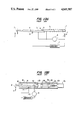
A prior art force-sensing probe is illustrated in FIG. 1(A). An object of the probe is to enable a clinician to obtain a standarized depth measurement of a periodontal pocket which surrounds a tooth, and which has a floor of periodontal tissue. The probe senses the level of the force at which the probe is placed in contact with the periodontal tissue at the floor of the pocket, and indicates when that level has reached a predetermined level, enabling a clinician to obtain a standardized depth measurement of the pocket by measuring the depth when that level has reached the predetermined level.
As illustrated in the figure, the prior art probe is comprised of a magnetizable member 1, a movable lever 2 which has a probe tip 3 at one end and which pivots around pivot pin 4, a coil 5 wrapped around magnetizable member 1, a power supply 6, a potentiometer 11, an annunicator 7, and a contact point 10. Power supply 6 is coupled to coil 5 causing a current to flow through the coil and magnetizing magnetizable member 1 to generate a magnetic force and releasably hold movable lever 2 in an "engaged" position. As illustrated, the power supply is also coupled in series to the movable lever, to the annunicator, and to the contact point. Movable lever 2 has a beveled surface 8 at one end, and magnetizable member 1 similarly has a beveled surface 9 at one end which is parallel to and flush with the beveled surface of the movable lever when the lever is in the "engaged" position.
To measure the depth of a periodontal pocket with the prior art probe, a clinician places the probe tip of the probe in contact with the periodontal tissue at the floor of the pocket. The periodontal tissue exerts a particular level of force on the probe tip, and the clinician adjusts the placing of the probe until the level of force exerted is equal to a predetermined level, defined as the level of force required to overcome the magnetic force releasably holding the movable lever in the "engaged" position. When the level of force is equal to the predetermined level and the magnetic force is overcome, the lever is caused to pivot around the pivot point and move to a "disengaged" position. In the "disengaged" position, the lever is placed in contact with contact point 10 thereby activating annunciator 7 which preferably consists of a buzzer, a lamp or the like. When activated, the annunicator visibly or audibly indicates that the level of force is equal to the predetermined level, and that the lever has moved to the "disengaged" position. After the lever has moved to the "disengaged" position, the clinician then reads the depth measurement from a depth measuring scale (not shown) incorporated within the probe and placed near the probe tip.
To enable the clinician to adjust the predetermined level of force required to overcome the magnetic force releasably holding the lever in the "engaged" position, a potentiometer 11 is provided. When the potentiometer is adjusted, the current flowing through coil 5 is altered, and the level of the magnetic force releasably holding lever 2 in the "engaged" position is proportionately changed.
A variant prior art probe is illustrated in FIG. 1(B). As illustrated in the figure, the variant prior art probe comprises a slidable permanent magnet 101 to which is attached a cylinder 102 of nonmagnetic material with an extended bore 103 for receiving the threaded end of a stub shaft 104. The opposite end of the stub shaft is attached to knob 105. When the knob is turned in a clockwise direction, the threaded end of the stub shaft is caused to progress within the extended bore thereby sliding the cylinder and the permanent magnet to which the cylinder is attached towards the knob across mountings 106.
The variant prior art probe further comprises a magnetizable member 107 which is fixed to a probe housing 108 by means of mountings 109, a movable lever 110 which pivots around pivot pin 111, a probe tip 112 attached to one end of the movable lever, and a battery 113 which is coupled in series to the movable lever. The battery is further coupled in series to an annunicator 115, and to a contact point 114.
Similarly to the prior art probe illustrated in FIG. 1(A), the movable lever is releasably held in an "engaged" position by a magnetic force exerted by the magnetizable member, and a predetermined level of force is required at the probe tip to overcome the magnetic force. The level of the magnetic force releasably holding the lever in the "engaged" position and hence the predetermined level of force required at the probe tip to overcome the magnetic force proportionately increases as the knob is moved in a counter-clockwise direction causing the slidable magnet to move closer to the magnetizable member. When the level of force at the probe tip is equal to the predetermined level, the lever is caused to pivot to a "disengaged" position, and contact the contact point thereby activating the annunciator. When activated, the annunciator visibly or audibly indicates that the level of force at the probe tip is equal to the predetermined level, and that the lever has moved to the "disengaged" position.
The prior art and variant prior art probes suffer from the disadvantage that the movable levers of such probes must be manually reset from the "disengaged" position to the "engaged" position after each measurement of pocket depth. Since a clinician must make an average of six measurements per tooth, such manual resetting is inefficient.
Another disadvantage is that such probes do not provide a clinician with a precise indication of the level of force at the probe tips of such probes when a depth measurement is taken, making the standardization of that measurement difficult. Instead, such probes only provide the clinician with an indication that the level of force is equal to or greater than the predetermined level, but do not indicate the extent to which the predetermined level is exceeded.
Accordingly, it is an object of the present invention to provide a force-sensing probe for obtaining standardized pocket depth measurements while the force exerted on the probe by the periodontal tissue at the floor of the pockets is equal to a predetermined level which, for each pocket depth measurement, senses and indicates the level of force exerted on the probe by the periodontal tissue at the floor of the pocket while the measurement is taken, and which then automatically resets in preparation for another measurement.
SUMMARY OF THE INVENTION
To achieve the foregoing objects, and in accordance with the purpose of the invention as embodied and broadly described herein, there is provided an automatically-resetting force-sensing probe for probing periodontal tissue comprising: a probe tip for placing in contact with the periodontal tissue at a particular level of force; automatically-resetting force-sensing means coupled to the probe tip for sensing that level of force and for producing a potential difference signal having a magnitude proportional to that level; and force-indicating means coupled to the force-sensing means for receiving that potential difference signal and visibly or audibly indicating the magnitude of the potential difference signal.
A related method of probing a periodontal pocket having a floor of periodontal tissue, and, more specifically, of obtaining a standardized depth measurement of the pocket, is also provided comprising the steps of: (a) placing a probe having force-sensing and force-indicating means in contact with the periodontal tissue at the floor of the pocket at a particular level of force; (b) sensing and indicating that level of force; (c) comparing that level of force with a predetermined level, and adjusting the placing of the probe until that level of force is equal to the predetermined level; (d) measuring the depth of the pocket while that level of force is equal to the predetermined level; and (e) automatically resetting the force-sensing and force-indicating means of the probe in preparation for another depth measurement.
BRIEF DESCRIPTION OF THE DRAWINGS
FIG. 1(A) is a schematic drawing of a prior art forcesensing probe;
FIG. 1(B) is a schematic drawing of a variant prior art force-sensing probe;
FIG. 2 is a schematic drawing of a force-sensing probe incorporating the teachings of the subject invention; and
FIG. 3 is a circuit diagram of the electronics assembly of the probe of the subject invention.
DESCRIPTION OF THE PREFERRED EMBODIMENT
A diagram of a probe incorporating the teachings of the subject invention is illustrated in FIG. 2. As illustrated in the figure, the probe preferably compriss probe tip 201, tip mount 202, bending beam 203, electronics assembly 204, pivot pin 205, strain gauges 206 and 207, flexible conductor 208, connector 209, and a series of light emitting diodes ("LEDs") 210. As shown, the probe tip is preferably coupled to the bending beam through the tip mount and the pivot pin. The strain gauges are mounted on the bending beam, and are coupled to the electronics assembly by means of the flexible conductor and by means of the connector. The electronics assembly is coupled to the series of LEDs.
When probe tip 201 is placed in contact with periodontal tissue, a force F is exerted on the probe tip by the tissue which produces a torque around pivot point 205. The torque, acting through tip mount 202, causes bending beam 203 to bend.
Strain gauges 206 and 207 are preferably coupled to electronic assembly 204 which together produce a potential difference signal having a magnitude proportional to the degree of bending of the bending beam. The strain gauges are coupled to the electronics assembly through flexible conductor 208 and connector 209. In the electronics assembly, the magnitude of the potential difference signal is amplified to produce an amplified potential difference signal having an amplified magnitude,and the amplified potential difference signal is used to light a selected LED within the series of LEDs 210. Each LED within the series has an index, and the index of the selected LED is proportional to the amplified magnitude.
A diagram of the electronics assembly is illustrated in FIG. 3. As illustrated in the figure, the electronics assembly preferably comprises amplifying circuitry 301, LED driver circuitry 302, and voltage supply circuitry 303. Also illustrated in the figure are strain gauges 206 and 207 and the series of LEDs 210 (from FIG. 2), which are all coupled to the electronics assembly.
The amplifying circuitry preferably comprises resistor 304, resistor 305, potentiometer 306, resistor 307, resistor 308, operational amplifier 309 having first and second input leads ( pins 3 and 2 respectively in FIG. 3) and an output lead (pin 6 in FIG. 3), potentiometer 310, resistor 311, and potentiometer 312.
Strain gauges 206 and 207 are preferably strain gauge resistors whose resistance changes in proportion to the bending of bending beam 203. The strain gauges are coupled to resistor 304, resistor 305, and potentiometer 306 to form a wheatstone bridge having circuit nodes 313 and 314. Circuit nodes 313 and 314 are respectively coupled to the first and second input leads of operational amplifier 309 by means of resistors 307 and 308 respectively.
The wheatstone bridge is balanced by means of potentiometer 306 which is preferably coupled in parallel to resistor 305. The wheatstone bridge is preferably balanced by adjusting potentiometer 306 when no bending of bending beam 203 is present until no potential difference is present between circuit nodes 313 and 314.
When a force is applied to the probe tip and the bending beam is caused to bend, the wheatstone bridge is placed out-of-balance, and a potential difference signal is induced between circuit nodes 313 and 314 having a magnitude which is proportional to the bending of the bending beam and the applied force. The magnitude of the induced potential difference signal is amplified by the operational amplifier to produce an amplified potential difference signal having an amplified magnitude at the output lead of the operational amplifier.
The amplified magnitude of the amplified potential difference signal will preferably range between 1.5 volts (when no force is exerted on the probe tip) to 2.7 volts (when a force having a predetermined level is exerted on the probe tip). The predetermined level is the level chosen with which to standardize periodontal pocket depth measurements, and preferably ranges from 3 to 130 grams. The amplified magnitude will preferably be adjusted to 1.5 volts by means of potentiometer 310 when no force is exerted on the probe tip, and will preferably be adjusted to 2.7 volts by means of potentiometer 312 when a force having a level equal to the predetermined level is exerted on the probe tip.
As shown in the figure, strain gauges 206 and 207 are preferably strain gauge resistors having resistances of 120 ohms when no bending of bending beam 203 is present, resistor 304 is preferably 121 ohms, resistor 305 is preferably 130 ohms, potentiometer 306 is preferably 5K ohms, resistors 307 and 308 are preferably 1.02K ohms, operational amplifier 309 is preferably a National Semiconductor LM725C operational amplifier, potentiometer 310 is preferably 5K ohms, resistor 311 is preferably 101 ohms, potentiometer 312 is preferably 1 Meg. ohms, and LED series 210 preferably comprises eight LEDs.
LED driver circuitry 302 preferably comprises capacitor 315, resistors 316-319, capacitor 320, and dot/bar display driver 321 having an input lead (pin 5 in FIG. 3) and having a plurality of output leads (pins 1, 12-18 in FIG. 3). The input lead is preferably coupled to the output lead of the operational amplifier, and the output leads are preferably coupled to the eight LEDs of LED series 210.
The dot/bar display driver preferably receives the amplifed potential difference signal from the operational amplifier, and lights a selected LED within the series of LEDs in response thereto. The index of the selected LED within the series is preferably proportional to the amplified magnitude of the amplified potential difference signal. The display driver preferably lights none of the LEDs within the series when the amplified magnitude of the amplified potential difference signal is 1.5 volts, but preferably lights the fifth LED within the series when the amplified magnitude is 2.7 volts.
As shown in the figure, capacitor 315 is preferably 0.33 microfarads, resistor 316 is preferably 4.02K ohms, resistor 317 is preferably 12.4K ohms, resistor 318 is preferably 1.02K ohms, resistor 319 is preferably 1.5K ohms, capacitor 320 is preferably 0.33 microfarads, and dot/bar display driver 321 is preferably a National Semiconductor LM3914 dot/bar display driver.
Voltage supply circuitry 303 preferably comprises battery 322, resistor 323, resistor 324, voltage regulator 325 having first and second input leads (pins 1 and 2 respectively in FIG. 3) and an output lead (pin 3 in FIG. 3), capacitor 326, and circuit node 327. The battery is preferably coupled to the first input lead of the voltage regulator, the resistors are preferably coupled to the second input lead of the voltage regulator and the output lead is preferably coupled to the amplifying circuitry and to the LED circuitry.
Voltage regulator 325 produces a voltage signal at circuit node 327 having a magnitude which is a fraction of the magnitude of the voltage of battery 322. The fraction is preferably proportional to the ratio of the resistance of resistors 323 and 324. The magnitude of the voltage signal is preferably sufficient to activate the amplifying circuitry and the LED circuitry. As shown in the figure, battery 322 is preferably seven volts, resistor 323 is preferably 2.67K ohms, resistor 324 is preferably 1.5K ohms, voltage regulator 325 is preferably a National Semiconductor LM317L 3-terminal adjustable regulator, and capacitor 326 is preferably 0.33 microfarads.
As is clear from the above descriptions, an automatically resetting force-sensing dental probe has been provided which solves the various problems posed by such prior art probes and allows efficient, accurate probing of a patient's periodontal pockets.
Additional advantages and modifications will readily occur to those skilled in the art. The invention in its broader aspects is not, therefore, limited to the specific details, representative methods, and illustrative examples shown and described. Accordingly, departures may be made from such details without departing from the spirit or scope of applicant's general inventive concept.

Claims (14)

What is claimed is:
1. An apparatus for probing periodontal tissue, comprising:
a housing for manipulating the apparatus;
a probe tip for engaging the periodontal tissue at a selected level of force;
a resilient beam portion connecting the probe tip to said housing, said beam portion extending in a predetermined angular alignment with said probe tip in the absence of force and being bendable from said predetermined angular alignment to another angular alignment in accordance with the force exerted against the probe tip;
strain gauge means coupled to the resilient beam portion operative to generate an electrical potential representative of the magnitude of the difference between said another angular alignment and the predetermined angular alignment; and
force indicating means responsive to said generated electrical potential for indicating the amount of force exerted against the probe tip.
2. The apparatus of claim 1, wherein said strain gauge means includes wheatstone bridge circuitry operative to generate said electrical potential.
3. The probe of claim 2 wherein said force-indicating means comprises
amplifying circuitry coupled to said wheatstone bridge circuitry for receiving and amplifying said potential difference signal to produce an amplified potential difference signal having an amplified magnitude;
light emitting diode ("LED") circuitry coupled to said amplifying circuitry for receiving said amplified potential difference signal and visibly indicating the amplified magnitude of said amplified potential difference signal; and
voltage supply circuitry coupled to said amplifying circuitry and to said LED circuitry for producing a voltage signal necessary to activate said amplifying circuitry and said LED circuitry.
4. The probe of claim 3 wherein said wheatstone bridge circuitry comprises a first resistor, a second resistor, and a potentiometer all having first and second leads wherein said first and second leads of said second resistor are respectively coupled to said first and second leads of said potentiometer to form a parallel combination also having first and second leads, and wherein said second lead of said parallel combination is coupled to said second lead of said first resistor to form a first circuit node.
5. The probe of claim 4 wherein said strain gauge resistors comprise first and second strain gauge resistors having first and second leads wherein said first leads of said strain gauge resistors are coupled together to form a second circuit node, and wherein said second leads of said first and second strain gauge resistors are respectively coupled to said first lead of said first resistor and to said first lead of said parallel combination so that said potential difference signal having a magnitude proportional to said bending of said bending beam is produced between said first and second circuit nodes.
6. The probe of claim 5 wherein said magnitude of said potential difference signal is adjusted to zero by means of said potentiometer when no bending of said bending beam is present.
7. The probe of claim 6 wherein said amplifying circuitry comprises operational amplifier circuitry having first and second input leads respectively coupled to said first and second circuit nodes for receiving said potential differential signal, and having an output lead on which is produced said amplified potential difference signal.
8. The probe of claim 7 wherein said LED circuitry comprises
a series of LEDs; and
driver circuitry coupled to said series of LEDs and coupled to said operational amplifier circuitry for receiving said amplified potential difference signal and then selecting and activating a selected LED within said series of LEDs in response thereto.
9. The probe of claim 8 wherein said series of LEDs comprise a plurality of LEDs, wherein each such LED has an index within said series, and wherein the index of said selected LED is proportional to said amplified magnitude of said amplified potential difference signal.
10. The probe of claim 9 wherein said driver circuitry has an input lead coupled to the output lead of said operational amplifier circuitry for receiving said amplified potential difference signal, and a plurality of output leads respectively coupled to said plurality of LEDs.
11. The probe of claim 10 wherein said amplifying circuitry further comprises adjusting means coupled to said operational amplifier circuitry for adjusting said amplified magnitude of said amplified potential difference circuitry.
12. The probe of claim 11 wherein said series of LEDs comprises eight LEDs, and wherein said amplified magnitude of said amplified potential difference signal is adjusted by means of said adjusting means to cause said driver circuitry to select and activate no LEDs within said series when no bending of said bending beam is present, and to select and activate the fifth LED within said series when a force having a predetermined level is exerted on said probe tip causing said bending beam to bend.
13. The probe of claim 12 wherein said adjusting means comprises first and second adjusting potentiometers.
14. The probe of claim 13 wherein said predetermined level of force ranges from 3 to 130 grams.
US07/069,190 1987-07-02 1987-07-02 Automatically resetting, force-sensing probe and related method of operation Expired - Fee Related US4841987A (en)

Priority Applications (1)

Application Number Priority Date Filing Date Title
US07/069,190 US4841987A (en) 1987-07-02 1987-07-02 Automatically resetting, force-sensing probe and related method of operation

Applications Claiming Priority (1)

Application Number Priority Date Filing Date Title
US07/069,190 US4841987A (en) 1987-07-02 1987-07-02 Automatically resetting, force-sensing probe and related method of operation

Publications (1)

Publication Number Publication Date
US4841987A true US4841987A (en) 1989-06-27

Family

ID=22087318

Family Applications (1)

Application Number Title Priority Date Filing Date
US07/069,190 Expired - Fee Related US4841987A (en) 1987-07-02 1987-07-02 Automatically resetting, force-sensing probe and related method of operation

Country Status (1)

Country Link
US (1) US4841987A (en)

Cited By (16)

* Cited by examiner, † Cited by third party
Publication number Priority date Publication date Assignee Title
US4979898A (en) * 1989-04-13 1990-12-25 Abraham Rand Measuring instruments particularly useful as dental implements
WO1991011141A1 (en) * 1990-01-29 1991-08-08 Biora Ab Apparatus for diagnosis
US5070859A (en) * 1989-09-05 1991-12-10 Narco-Med Ag. Laryngoscope
US5536245A (en) * 1994-11-23 1996-07-16 Dahlbeck; Scott Laryngoscope pressure sensor and alarm
EP0724413A1 (en) * 1993-10-19 1996-08-07 RAMOT UNIVERSITY AUTHORITY FOR APPLIED RESEARCH & INDUSTRIAL DEVELOPMENT LTD. Method and apparatus for measuring tooth tightness
WO1996039934A1 (en) * 1995-06-07 1996-12-19 Morton John Y Device and method for measuring force systems
ES2110363A1 (en) * 1995-09-22 1998-02-01 Fundacio Josep Finestres Apparatus for measuring forces, particularly for medicine and dentistry
US6969384B2 (en) * 2000-01-03 2005-11-29 The Johns Hopkins University Surgical devices and methods of use thereof for enhanced tactile perception
US20110046659A1 (en) * 2007-07-09 2011-02-24 Immersion Corporation Minimally Invasive Surgical Tools With Haptic Feedback
US20110303787A1 (en) * 2008-11-17 2011-12-15 Ian Robert Bennett Load Indicator
US20120202165A1 (en) * 2009-08-12 2012-08-09 Ashish Kakar Apparatus and method for measuring dentin hypersensitivity
US8523043B2 (en) 2010-12-07 2013-09-03 Immersion Corporation Surgical stapler having haptic feedback
US8801710B2 (en) 2010-12-07 2014-08-12 Immersion Corporation Electrosurgical sealing tool having haptic feedback
US8845667B2 (en) 2011-07-18 2014-09-30 Immersion Corporation Surgical tool having a programmable rotary module for providing haptic feedback
US9579143B2 (en) 2010-08-12 2017-02-28 Immersion Corporation Electrosurgical tool having tactile feedback
CN114587682A (en) * 2022-03-17 2022-06-07 宁波市第一医院 Rated force gingival sulcus depth detector and rated force calibration method

Citations (16)

* Cited by examiner, † Cited by third party
Publication number Priority date Publication date Assignee Title
US3058225A (en) * 1958-04-01 1962-10-16 Howard L Ward Probing instrument and depth indicator
US3943914A (en) * 1973-08-06 1976-03-16 Grenfell James W Remote-recording periodontal depth probe
US4058115A (en) * 1974-11-06 1977-11-15 Forster F M O Method and apparatus for examining human periodontal tissues
US4132224A (en) * 1977-01-12 1979-01-02 Randolph Robert G Durometer for indentible tissue and the like
US4182312A (en) * 1977-05-20 1980-01-08 Mushabac David R Dental probe
US4192321A (en) * 1977-07-22 1980-03-11 Heinz Dehnert Tooth displacement measuring apparatus
US4204544A (en) * 1977-09-30 1980-05-27 California Institute Of Technology Simultaneous muscle force and displacement transducer
US4250895A (en) * 1979-03-23 1981-02-17 Forsyth Dental Infirmary For Children Periodontal probe
FR2490949A1 (en) * 1980-10-01 1982-04-02 Deschamps Jean Claude Lumbar region isostatic therapy appts. - uses piezo-resistive rubber pads associated with LED's and acoustic source to indicate movement of patient
US4340069A (en) * 1979-10-17 1982-07-20 Yeaple Corporation Force-sensitive probe and method of use
EP0061218A1 (en) * 1981-03-16 1982-09-29 S.B.R.-Trading B.V. Pocket meter for dental cavities
US4459109A (en) * 1981-11-25 1984-07-10 Myo-Tronics Research, Inc. Kinesiograph sensor array alignment system
EP0194083A1 (en) * 1985-02-26 1986-09-10 Foster-Miller, Inc. Periodontal analysis apparatus
US4622751A (en) * 1985-07-16 1986-11-18 Berg John W Precision electromechanical measuring device
US4677756A (en) * 1985-03-21 1987-07-07 Vs Remek Limited Measuring instruments for measuring depth of cavities
US4708647A (en) * 1986-03-07 1987-11-24 The Curators Of The University Of Missouri Periodontal probe instrument

Patent Citations (16)

* Cited by examiner, † Cited by third party
Publication number Priority date Publication date Assignee Title
US3058225A (en) * 1958-04-01 1962-10-16 Howard L Ward Probing instrument and depth indicator
US3943914A (en) * 1973-08-06 1976-03-16 Grenfell James W Remote-recording periodontal depth probe
US4058115A (en) * 1974-11-06 1977-11-15 Forster F M O Method and apparatus for examining human periodontal tissues
US4132224A (en) * 1977-01-12 1979-01-02 Randolph Robert G Durometer for indentible tissue and the like
US4182312A (en) * 1977-05-20 1980-01-08 Mushabac David R Dental probe
US4192321A (en) * 1977-07-22 1980-03-11 Heinz Dehnert Tooth displacement measuring apparatus
US4204544A (en) * 1977-09-30 1980-05-27 California Institute Of Technology Simultaneous muscle force and displacement transducer
US4250895A (en) * 1979-03-23 1981-02-17 Forsyth Dental Infirmary For Children Periodontal probe
US4340069A (en) * 1979-10-17 1982-07-20 Yeaple Corporation Force-sensitive probe and method of use
FR2490949A1 (en) * 1980-10-01 1982-04-02 Deschamps Jean Claude Lumbar region isostatic therapy appts. - uses piezo-resistive rubber pads associated with LED's and acoustic source to indicate movement of patient
EP0061218A1 (en) * 1981-03-16 1982-09-29 S.B.R.-Trading B.V. Pocket meter for dental cavities
US4459109A (en) * 1981-11-25 1984-07-10 Myo-Tronics Research, Inc. Kinesiograph sensor array alignment system
EP0194083A1 (en) * 1985-02-26 1986-09-10 Foster-Miller, Inc. Periodontal analysis apparatus
US4677756A (en) * 1985-03-21 1987-07-07 Vs Remek Limited Measuring instruments for measuring depth of cavities
US4622751A (en) * 1985-07-16 1986-11-18 Berg John W Precision electromechanical measuring device
US4708647A (en) * 1986-03-07 1987-11-24 The Curators Of The University Of Missouri Periodontal probe instrument

Non-Patent Citations (4)

* Cited by examiner, † Cited by third party
Title
"A Pressure-Sensitive Periodontal Probe", Gabathuler et al., Helv. Odant. Acta, Oct. 1971.
"Introduction of a New Periodontal Probe: the Pressure Probe", Van Ier Velden et al., J. of Clin. Peri., 1978.
A Pressure Sensitive Periodontal Probe , Gabathuler et al., Helv. Odant. Acta, Oct. 1971. *
Introduction of a New Periodontal Probe: the Pressure Probe , Van Ier Velden et al., J. of Clin. Peri., 1978. *

Cited By (20)

* Cited by examiner, † Cited by third party
Publication number Priority date Publication date Assignee Title
US4979898A (en) * 1989-04-13 1990-12-25 Abraham Rand Measuring instruments particularly useful as dental implements
US5070859A (en) * 1989-09-05 1991-12-10 Narco-Med Ag. Laryngoscope
WO1991011141A1 (en) * 1990-01-29 1991-08-08 Biora Ab Apparatus for diagnosis
US5327903A (en) * 1990-01-29 1994-07-12 Biora Ab Apparatus for diagnosing periodontitis
EP0724413A1 (en) * 1993-10-19 1996-08-07 RAMOT UNIVERSITY AUTHORITY FOR APPLIED RESEARCH & INDUSTRIAL DEVELOPMENT LTD. Method and apparatus for measuring tooth tightness
EP0724413A4 (en) * 1993-10-19 1997-11-05 Univ Ramot Method and apparatus for measuring tooth tightness
US5536245A (en) * 1994-11-23 1996-07-16 Dahlbeck; Scott Laryngoscope pressure sensor and alarm
WO1996039934A1 (en) * 1995-06-07 1996-12-19 Morton John Y Device and method for measuring force systems
ES2110363A1 (en) * 1995-09-22 1998-02-01 Fundacio Josep Finestres Apparatus for measuring forces, particularly for medicine and dentistry
US6969384B2 (en) * 2000-01-03 2005-11-29 The Johns Hopkins University Surgical devices and methods of use thereof for enhanced tactile perception
US20110046659A1 (en) * 2007-07-09 2011-02-24 Immersion Corporation Minimally Invasive Surgical Tools With Haptic Feedback
US20110303787A1 (en) * 2008-11-17 2011-12-15 Ian Robert Bennett Load Indicator
US8800382B2 (en) * 2008-11-17 2014-08-12 Messier-Dowty Limited Load indicator
US20120202165A1 (en) * 2009-08-12 2012-08-09 Ashish Kakar Apparatus and method for measuring dentin hypersensitivity
US8579630B2 (en) * 2009-08-12 2013-11-12 Ashish Kakar Apparatus and method for measuring dentin hypersensitivity
US9579143B2 (en) 2010-08-12 2017-02-28 Immersion Corporation Electrosurgical tool having tactile feedback
US8523043B2 (en) 2010-12-07 2013-09-03 Immersion Corporation Surgical stapler having haptic feedback
US8801710B2 (en) 2010-12-07 2014-08-12 Immersion Corporation Electrosurgical sealing tool having haptic feedback
US8845667B2 (en) 2011-07-18 2014-09-30 Immersion Corporation Surgical tool having a programmable rotary module for providing haptic feedback
CN114587682A (en) * 2022-03-17 2022-06-07 宁波市第一医院 Rated force gingival sulcus depth detector and rated force calibration method

Similar Documents

Publication Publication Date Title
US4841987A (en) Automatically resetting, force-sensing probe and related method of operation
US4660666A (en) Strain gauge scale for weighing fish
US5386188A (en) In-circuit current measurement
US5471885A (en) Self-contained digital electronic force gage with interchangeable force sensor modules
US4340069A (en) Force-sensitive probe and method of use
US4257107A (en) Measuring device
GB2102578A (en) Measuring surface temperatures using platinum resistive sensors
US6758098B1 (en) Force-measuring clamp
EP0099712B1 (en) Flowmeters
GB2136579A (en) Thermal anemometer
EP0228180A1 (en) Systems to display saw blade angle and height
JP2647503B2 (en) Differential pressure transmitter
US2546155A (en) Deflection indicator
US3500547A (en) Precise calipers with automatic printout
US4448078A (en) Three-wire static strain gage apparatus
US3580081A (en) Vacuum gauge
US3431781A (en) Clinical thermometer
US3441846A (en) Digital readout instrument employing a non-linear transducer and a linear potentiometer
US3992945A (en) Bourdon pressure gauge having direct-coupled electronic and visual readout
US4291465A (en) Caliper rule device having extended measurement range
US4506847A (en) Thermalling sailplane turn indicator
US4078179A (en) Movable instrument with light emitting position indicator
JPS5975111A (en) Display device of dial gauge
Lacey et al. An improved potentiometric circuit for measuring the galvanic skin response
US3210992A (en) Ultrasensitive force and speed measuring device

Legal Events

Date Code Title Description
AS Assignment

Owner name: ACCUDENT, INC., 1014 RESERVOIR STREET, SUITE B, HA

Free format text: ASSIGNMENT OF ASSIGNORS INTEREST.;ASSIGNORS:BROWN, STEPHEN J.;POND, STANLEY L.;REEL/FRAME:004757/0807;SIGNING DATES FROM 19870618 TO 19870623

FEPP Fee payment procedure

Free format text: PAYOR NUMBER ASSIGNED (ORIGINAL EVENT CODE: ASPN); ENTITY STATUS OF PATENT OWNER: SMALL ENTITY

FEPP Fee payment procedure

Free format text: PAT HOLDER CLAIMS SMALL ENTITY STATUS - SMALL BUSINESS (ORIGINAL EVENT CODE: SM02); ENTITY STATUS OF PATENT OWNER: SMALL ENTITY

REFU Refund

Free format text: REFUND OF EXCESS PAYMENTS PROCESSED (ORIGINAL EVENT CODE: R169); ENTITY STATUS OF PATENT OWNER: SMALL ENTITY

FPAY Fee payment

Year of fee payment: 4

REMI Maintenance fee reminder mailed
LAPS Lapse for failure to pay maintenance fees
FP Lapsed due to failure to pay maintenance fee

Effective date: 19970702

STCH Information on status: patent discontinuation

Free format text: PATENT EXPIRED DUE TO NONPAYMENT OF MAINTENANCE FEES UNDER 37 CFR 1.362